EP3348048B1 - Plenoptic camera - Google Patents
Plenoptic camera Download PDFInfo
- Publication number
- EP3348048B1 EP3348048B1 EP16785184.9A EP16785184A EP3348048B1 EP 3348048 B1 EP3348048 B1 EP 3348048B1 EP 16785184 A EP16785184 A EP 16785184A EP 3348048 B1 EP3348048 B1 EP 3348048B1
- Authority
- EP
- European Patent Office
- Prior art keywords
- optical elements
- plenoptic camera
- distance
- array
- pixels
- Prior art date
- Legal status (The legal status is an assumption and is not a legal conclusion. Google has not performed a legal analysis and makes no representation as to the accuracy of the status listed.)
- Active
Links
- 230000003287 optical effect Effects 0.000 claims description 101
- 239000011159 matrix material Substances 0.000 claims description 14
- 230000001788 irregular Effects 0.000 claims description 10
- 230000003595 spectral effect Effects 0.000 claims description 9
- 238000000034 method Methods 0.000 claims description 2
- 229920000297 Rayon Polymers 0.000 description 2
- 238000003491 array Methods 0.000 description 2
- 238000001914 filtration Methods 0.000 description 2
- 230000000737 periodic effect Effects 0.000 description 2
- 239000002964 rayon Substances 0.000 description 2
- 230000005670 electromagnetic radiation Effects 0.000 description 1
- 238000005286 illumination Methods 0.000 description 1
- 239000004973 liquid crystal related substance Substances 0.000 description 1
- 230000000873 masking effect Effects 0.000 description 1
- 238000005259 measurement Methods 0.000 description 1
- 238000000926 separation method Methods 0.000 description 1
- 230000026676 system process Effects 0.000 description 1
- 230000004304 visual acuity Effects 0.000 description 1
Images


Classifications
-
- G—PHYSICS
- G03—PHOTOGRAPHY; CINEMATOGRAPHY; ANALOGOUS TECHNIQUES USING WAVES OTHER THAN OPTICAL WAVES; ELECTROGRAPHY; HOLOGRAPHY
- G03B—APPARATUS OR ARRANGEMENTS FOR TAKING PHOTOGRAPHS OR FOR PROJECTING OR VIEWING THEM; APPARATUS OR ARRANGEMENTS EMPLOYING ANALOGOUS TECHNIQUES USING WAVES OTHER THAN OPTICAL WAVES; ACCESSORIES THEREFOR
- G03B35/00—Stereoscopic photography
- G03B35/08—Stereoscopic photography by simultaneous recording
-
- G—PHYSICS
- G06—COMPUTING; CALCULATING OR COUNTING
- G06T—IMAGE DATA PROCESSING OR GENERATION, IN GENERAL
- G06T7/00—Image analysis
- G06T7/50—Depth or shape recovery
- G06T7/55—Depth or shape recovery from multiple images
- G06T7/557—Depth or shape recovery from multiple images from light fields, e.g. from plenoptic cameras
-
- H—ELECTRICITY
- H04—ELECTRIC COMMUNICATION TECHNIQUE
- H04N—PICTORIAL COMMUNICATION, e.g. TELEVISION
- H04N13/00—Stereoscopic video systems; Multi-view video systems; Details thereof
- H04N13/20—Image signal generators
- H04N13/204—Image signal generators using stereoscopic image cameras
- H04N13/207—Image signal generators using stereoscopic image cameras using a single 2D image sensor
- H04N13/232—Image signal generators using stereoscopic image cameras using a single 2D image sensor using fly-eye lenses, e.g. arrangements of circular lenses
-
- H—ELECTRICITY
- H04—ELECTRIC COMMUNICATION TECHNIQUE
- H04N—PICTORIAL COMMUNICATION, e.g. TELEVISION
- H04N13/00—Stereoscopic video systems; Multi-view video systems; Details thereof
- H04N13/20—Image signal generators
- H04N13/204—Image signal generators using stereoscopic image cameras
- H04N13/246—Calibration of cameras
-
- H—ELECTRICITY
- H04—ELECTRIC COMMUNICATION TECHNIQUE
- H04N—PICTORIAL COMMUNICATION, e.g. TELEVISION
- H04N23/00—Cameras or camera modules comprising electronic image sensors; Control thereof
- H04N23/56—Cameras or camera modules comprising electronic image sensors; Control thereof provided with illuminating means
-
- H—ELECTRICITY
- H04—ELECTRIC COMMUNICATION TECHNIQUE
- H04N—PICTORIAL COMMUNICATION, e.g. TELEVISION
- H04N23/00—Cameras or camera modules comprising electronic image sensors; Control thereof
- H04N23/60—Control of cameras or camera modules
- H04N23/67—Focus control based on electronic image sensor signals
- H04N23/672—Focus control based on electronic image sensor signals based on the phase difference signals
-
- H—ELECTRICITY
- H04—ELECTRIC COMMUNICATION TECHNIQUE
- H04N—PICTORIAL COMMUNICATION, e.g. TELEVISION
- H04N23/00—Cameras or camera modules comprising electronic image sensors; Control thereof
- H04N23/95—Computational photography systems, e.g. light-field imaging systems
- H04N23/957—Light-field or plenoptic cameras or camera modules
Definitions
- the present invention relates to the field of 3D reconstruction from 2D images and in particular to plenoptic cameras which make it possible to acquire a 3D scene.
- 3D reconstruction from 2D images consists of obtaining a three-dimensional representation of an object or a scene from a set of 2D images of the object or of the scene taken from different points of view. .
- the points visible on the images are the projections of the real points that we can then locate on straight lines. If two or more views of the object are taken, the position in space of the real points can then be obtained by intersection of these lines (or triangulation).
- Using a plenoptic camera 1 has the advantage of having a relatively simple assembly to produce and requiring only one camera.
- the extrinsic calibration parameters are known.
- a plenoptic camera 1 captures information concerning the orientation distribution of the light rays entering the camera 1.
- this camera 1 comprises a main lens 2 which receives light from objects placed in a field object and directs the light received onto an image plane of the camera 1. This camera 1 samples the light field.
- each microlens receives all the rays coming from the object point conjugated to this center, these rays corresponding to different directions.
- the microlens then distribute the rays from different directions over several pixels of a photosensitive sensor 3. We therefore sampled the light field in position and in orientation. Each pixel thus receives light from a single ray.
- the association between pixel and rays is essential for three-dimensional reconstruction.
- the image taken by the photosensitive sensor 3 therefore contains sufficient information to form images seen from different points of view.
- the pixels receiving the light coming from the same microlens 4 form a group called a macropixel.
- the microlenses 4 are aligned in a regular array, the distance between two neighboring microlenses 4 being constant in at least two directions.
- the microlenses 4 can be arranged in regularly spaced rows and columns.
- Sensors are also known in which the microlenses are not aligned along rows and columns, but form a periodic assembly of small matrices (for example 3 by 3).
- An example is given by the document US2014 / 0327763 A1 , which also uses lenses of different sizes.
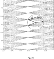
- the figure 3a allows to visualize this phenomenon.
- the figure 3a corresponds to a portion of the object space in which the optical paths of the incident beams on each pixel of the photosensitive sensor have been plotted 3.
- the points of intersections (marked by crosses) between these beams therefore correspond to the points of the object space which are imaged on at least two pixels.
- the intersections are poorly distributed in model space.
- plans (like plans -16.8 and -16.5 on the figure 3a ) in which the density of intersections is high, but there are also many planes (such as plane 16.65) in which the density of intersections is low, and large neighboring areas of these planes in which there is no intersection (like the area between planes -16.75 and -16.65 on the figure 3a ), in other words areas that are not imaged on at least two pixels. This is in particular due to the existence of many multiple intersections, which correspond to points in space which are imaged over more than two pixels.
- the figure 3b illustrates the fact that there are points whose distance to the nearest intersection is of the order of 50 micrometers.
- the resolving power of a plenoptic camera defined as the minimum distance that must separate two contiguous points for them to be imaged on pairs of different pixels, depends on the distribution of intersections in object space.
- the plenoptic cameras of the prior art therefore have good resolution in certain planes, on the other hand, they have poor overall resolution in space.
- An aim of the invention is to provide a plenoptic camera having better spatial resolution than the devices of the prior art.
- a plenoptic camera comprising an optical system which receives light coming from an object field in which is an object space intended to be processed via the camera, a matrix photosensitive sensor which is composed of pixels arranged in rows and columns and such that each pixel receives the light of a single ray of light via the optical system.
- Said camera has its optics which comprises a focusing optic and an array of optical elements which are positioned in an image plane located between the focusing optic and the photosensitive sensor.
- Each optical element forms a macropixel image on the photosensitive sensor by making its associated light ray correspond to each pixel.
- the optical elements are arranged in rows and columns parallel respectively to the rows and columns of the matrix sensor, forming the intersections in the object field,
- the distance which separates two adjacent lines of the network of optical elements and / or the distance which separates two adjacent columns of the network of optical elements is irregular in said network, this distance being distinct for at least two pairs of lines adjacent and / or two pairs of adjacent columns of the array of optical elements, the irregularity in separation distance making it possible to minimize the greatest distance between any point in object space and the closest to said intersections of these light rays.
- the distance between two adjacent lines, respectively two columns, is said to be irregular if it cannot be deduced from the knowledge of all the other distances between adjacent lines, respectively columns, or if the distance between at least twenty lines must be known, respectively twenty columns, adjacent to deduce it.
- the distance between two columns is fixed randomly, in particular by using a drawing according to a uniform law over a predetermined interval.
- the distance which separates two adjacent columns (or rows) of the array of optical elements is irregular from the moment when the difference between a value and the mean value is greater than 2% of the mean value (this condition is however not sufficient).
- the invention therefore makes it possible to improve the resolution of three-dimensional reconstruction of a plenoptic camera.
- the points of space imaged on at least two pixels are distributed more homogeneously in space, which makes it possible to have a better overall resolution in space.
- the light rays associated with their pixel form intersections in said object space and on the other hand the optics are made so as to minimize the greatest distance between any point in the object space and the closest to said intersections of these light rays.
- the invention is advantageously completed by the following characteristics, taken individually or in any of their technically possible combinations.
- the array of optical elements exhibits irregularities both as regards the distance which separates two adjacent lines of the array and as regards the distance which separates two adjacent columns.
- the fact that the array of optical elements comprises irregularities in two directions further improves the distribution of the points of space imaged over more than two pixels.
- the distance between two adjacent rows and / or two adjacent columns can for example be chosen randomly. Preferably, this distance is in a range of values between 95% and 105% of an average value. The tests carried out by the inventors made it possible to determine that this configuration allowed an increased resolution of the plenoptic camera.
- the macropixel image formed on the photosensitive sensor extends over at least two pixels in the vertical direction and / or in the horizontal direction and on the other hand the irregular distance in said network separates two adjacent lines of the network d 'optical elements in correspondence of their macropixel images of at least two pixels in the vertical direction and / or separates two adjacent columns of the array of optical elements in correspondence of their macropixel images of at least two pixels in the horizontal direction.
- Optical elements are microlenses or pinholes.
- the association between ray and pixel is dynamically chosen from a set of possible associations and makes it possible to obtain an image or more images of the object field.
- a set of controllable shutter elements positioned opposite the optical elements allows the dynamic selection of a single ray for each pixel by allowing the selection of an association from the set of possible associations, the images being formed by the optical elements on the detector and possibly having overlaps.
- a configuration of optical elements is first designed, possibly having overlaps between the macropixels, and a matrix mask is placed in front of or behind the plane of the array of optical elements.
- a matrix mask is placed in front of or behind the plane of the array of optical elements.
- the association between ray and pixels is one-to-one for at least 2 spectral bands, the associations corresponding to these spectral bands differing for at least 1 pixels.
- a set of chromatic filtering elements positioned opposite the optical elements ensures the uniqueness of the ray corresponding to each pixel in each of the spectral bands, making it possible to obtain one or more images of the object field, the images formed by the optical elements on the detector which may have overlaps.
- one passes dynamically from one configuration to another, by changing the wavelength of the lighting to make it correspond to the wavelength of the filters positioned in front of the array of optical elements corresponding to the desired configuration.
- the plenoptic camera can include two arrays of optical elements contained in the same plane, a chromatic filter allowing only wavelengths in a first frequency band to pass, being positioned in front of the optical elements. of the first network, a band-pass filter allowing only the wavelengths in a second frequency band different from the first frequency band to pass, being positioned in front of the optical elements of the second network.
- the invention also proposes a three-dimensional acquisition device, comprising a plenoptic camera as described above and a computer configured to determine, from the image supplied and / or a series of images supplied by the plenoptic camera, a distance between a point in the object field and the plenoptic camera.
- the invention also proposes the use of a three-dimensional acquisition device as described above for checking the shape and in particular for checking the shape of a turbomachine blade.
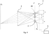
- a plenoptic camera 1 usually comprises a focusing optic 2, a photosensitive sensor 3, and an array of optical elements 40.
- An optical system comprises the focusing optic 2 and the array of optical elements 40.
- the focusing optic 2 is conventionally an optical lens or a combination of optical lenses, which receives light from objects placed in an object field.
- the plenoptic camera 1 has its optical elements 40 arranged in an image plane F 'of the plenoptic camera between the focusing optics 2 and the photosensitive sensor 3, and parallel to the sensor.
- the photosensitive sensor 3 is located at a plane referenced F "in the examples which are in the figures.
- Each optical element 4 forms on the photosensitive sensor 3 an image of the focusing optics 2.
- a point included in the plane Fc of the plane of the optical elements is imaged by a single microlens constituting a single optical element 4.
- the parameters of the camera, in particular the focal length of the focusing optics 2 and that of the microlenses 4 are chosen so that the images formed by the microlenses on the photosensitive sensor 3 do not overlap.
- the pixels receiving the light coming from the same optical element 4 form a group called a macropixel and each optical element 4 forms on the photosensitive sensor 3 a macropixel image extending over at least two pixels for said group, in the horizontal direction and / or in the vertical direction.
- the photosensitive sensor 3 is a matrix being composed of pixels arranged in rows and columns and such that each pixel receives the light of a single light ray via the optical system.
- the image taken by the photosensitive sensor 3 therefore contains sufficient information to form images seen from different points of view.
- the array of optical elements 40 is placed at a small distance (of the order of 0.5 mm) from the photosensitive sensor 3.
- the optical elements 4 can in particular be microlenses, or pinholes. In the case where the optical elements 4 are microlenses, these can be spherical or have a more complex shape allowing a junction between two adjacent microlenses 4. Microlenses typically have a diameter of the order of a fraction of a millimeter.
- the array of optical elements 40 is an opaque flat surface in which very small diameter holes are formed, typically spaced on the order of a fraction of a millimeter.
- the photosensitive sensor 3 captures the light received to produce an image.
- the photosensitive sensor 3 is a matrix sensor and typically a CCD matrix.
- the photosensitive sensor 3 is a photosensitive electronic component made up of photosites adapted to convert electromagnetic radiation (UV, visible or IR) into an analog electrical signal. This signal is then digitized by an analog-to-digital converter to obtain a digital image composed of pixels, each pixel corresponding to a photosite of the photosensitive sensor 3.
- the optical elements 4 are arranged in a coplanar manner, in a plane substantially parallel to the plane of the photosensitive sensor 3.
- the optical elements 4 are arranged so that their optical centers are aligned in rows and columns.
- the optical center of an optical element is the particular point of an optical element such that a light ray incident at this point is not deflected, its incident and emergent parts being parallel to each other.
- the optical center of the microlens is the point of intersection between the plane of the microlens and the optical axis.
- the optical center of the pinhole is the center of the hole.
- the distance between two adjacent rows is not constant, while the distance between two columns is constant, or alternatively, the distance between two adjacent rows is constant, but the distance between two columns n is not constant.
- neither the distance between two adjacent rows, nor the distance between two adjacent columns, are constant.
- the distance between two adjacent lines and that between two columns is typically less than a millimeter.
- the distance between two adjacent rows and / or that between two adjacent columns is typically chosen from a range of values between + and - 5% of an average value.
- the distance between two adjacent rows and / or that between two adjacent columns is typically chosen from a range of values between + and - 10% of an average value.
- the distance between two adjacent lines, respectively two columns, is irregular if it cannot be deduced from knowing all the other distances between adjacent lines, respectively columns, or if the distance between at least twenty lines must be known, respectively twenty columns, adjacent to deduce it.
- the distance between two adjacent rows and / or between two adjacent columns can for example be chosen randomly. This is understood to mean that in this case, the distribution of the distances between two adjacent lines and / or between two adjacent columns does not have any identifiable structure, regularity, or rule of prediction, in other words that the distance between two adjacent lines and / or between two adjacent columns is drawn at random. In fact, the tests carried out by the inventors made it possible to determine that this configuration allowed an increased three-dimensional reconstruction resolution of the plenoptic camera.
- the distance between two adjacent rows and / or that between two adjacent columns is typically chosen randomly from a range of values between + and - 5% around an average value.
- the distance between two adjacent rows and / or that between two adjacent columns is chosen randomly from a range of values between + and - 10% of an average value.
- An advantageous embodiment therefore consists in determining the distance between two columns (respectively rows) at random, in particular by using a drawing according to a uniform law over a predetermined interval of values.
- said distance is a function of a random value.
- the figure 6a corresponds to a portion of the object space in which the light rays corresponding to all the pixels have been traced.
- the points (marked by crosses) of intersections between these rays correspond to the points of model space which are imaged on at least two pixels.
- the intersections are distributed more homogeneously in space, which makes it possible to have a better overall resolution in space.
- the invention therefore makes it possible to improve the resolution of three-dimensional reconstruction of a plenoptic camera.
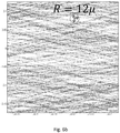
- the figure 6b enlargement of the figure 6a , illustrates that the point of the volume furthest from any intersection is only 12 microns from the nearest intersection.
- the three-dimensional reconstruction resolution is therefore significantly better.
- the arrangement of the optical elements 4 is advantageously modified dynamically in order to be able to adapt to particular situations.
- the arrangement of the optical elements 4 determines the positioning of the intersections, and therefore the resolution of the three-dimensional measurement in space.
- the configuration of the network of optical elements 40 will therefore be chosen as a function of the distribution of the intersections sought.
- a configuration can generate a high concentration of intersections in a particular zone of space and will be particularly interesting for acquiring an object contained in this zone of space.
- the optical system processes the light coming from the object field in which the object space is processed via the camera.
- the light rays associated with each one with their pixel form intersections in said object space and on the other hand the optics are produced so as to minimize the greatest distance between any point in the object space and the closest of said intersections of these light rays.
- Each optical element 4 forms on the photosensitive sensor 3 a macropixel image extending over at least two pixels in the vertical direction and / or in the horizontal direction by making each pixel its associated light ray.
- the optical elements 4 are aligned arranged in lines and in columns parallel respectively to the lines and columns of the matrix sensor 3, forming the intersections in the object field.
- the distance between two adjacent lines of the array of optical elements in correspondence of their macropixel images of at least two pixels in the vertical direction and / or the distance between two adjacent columns of the array of optical elements in correspondence of their images macropixels of at least two pixels in the horizontal direction is irregular in said grating. This irregularity in said distances separating said rows and / or columns makes it possible to minimize the greatest distance between any point in object space and the closest to said intersections of these light rays,
- the optical elements 4 can be moved.
- a movement of the optical elements 4 can in particular be obtained using actuators adapted to independently move each optical element 4.
- a matrix mask 50 positioned in front of or behind the array of optical elements 40, as illustrated in FIG. figure 7 , and made up of cells that can be controlled independently of each other to allow light to pass or not, for example a liquid crystal screen.
- a configuration of optical elements 4 is first designed, possibly having overlaps between the macropixels, and a matrix mask 50 is placed in front of or behind the plane of the array of optical elements 40.
- the rays coming from the optical elements 40 are dynamically modified in order to prevent more than one ray from reaching each pixel and to distribute the intersections in space.
- the set of intersections of the rays is enriched and the resolution of three-dimensional reconstruction is improved.
- the association between ray and pixel is dynamically chosen from a set of possible associations and makes it possible to obtain an image or more images of the object field.
- a set of controllable shutter elements positioned opposite the optical elements 4 so as to allow the dynamic selection of a single ray for each pixel by allowing the selection of an association in the set of 'possible associations. Since the images are formed by the optical elements 4 on the detector 3, they may have overlaps,
- Another way to dynamically change the geometry of the optical elements 4 is to position, as illustrated in the figure 8 , two arrays of optical elements 41, 42 in the same plane, and to position, in front of each optical element 4 of the first network 41 a band-pass filter 61 allowing only the wavelengths to pass in a first frequency band, and in front of each optical element 4 of the second network 42 a band-pass filter 62 allowing only the wavelengths to pass in a second frequency band different from the first frequency band.
- the networks 41 and 42 are made in such a way as to prevent more than one ray in each frequency band from reaching a pixel.
- the association between ray and pixels is one-to-one for at least 2 spectral bands, the associations corresponding to these spectral bands differing for at least 1 pixels.
- a calibration step one determines, for each point of the object field, the pixels on which the point of the object field is imaged.
- We associate with each point of the object field the pixels on which said point of the object field is imaged.
- the point in the object field must at least be imaged on two different pixels.
- the calibration can be carried out by lighting a single point of the object field at a time and by listing the pixels of the photosensitive sensor 3 illuminated, and this for a sample of points of the object space corresponding to the desired resolution.
- a screen is positioned in a plane normal to the direction of observation of the camera 1, and this screen gradually moves towards the sensor 3, in steps less than the desired distance resolution.
- each point of the screen is selectively lit in turn.
- at least the two most illuminated pixels of the sensor 3 are determined. If their level of illumination is sufficient, in practice greater than a chosen threshold, the point is associated with the pair of illuminated pixels.
- a table is thus created associating with a point of the object field the pair of pixels of the photosensitive sensor 2 on which said point is imaged.
- a three-dimensional acquisition device comprises a plenoptic camera 1, and a computer 5 configured to determine, from the image supplied or from the set of images supplied by the photosensitive sensor 3, a distance between a point of the field object and plenoptic camera 1.
- the computer 5 is configured to implement association and three-dimensional reconstruction steps as described below.
- the computer 5 associates with each other the different pixels which correspond to the same point of the object field. This is what allows the determination of the 3D coordinates of the points of the scene by triangulation.
- the different pixels which correspond to the same point of the object field are associated in a conventional manner.
- the computer 5 determines, by triangulation, the 3D coordinates of the points of the object field from the associations made and the calibration parameters of the plenoptic camera 1.
- the points visible on the images being the projections of the point of the object field, the position in space of the point of the object field is obtained by intersection of the light rays associated with the image pixels of the point of the object field.
Description
La présente invention se rapporte au domaine de la reconstruction 3D à partir d'images 2D et en particulier aux caméras plénoptiques qui permettent d'acquérir une scène en 3D.The present invention relates to the field of 3D reconstruction from 2D images and in particular to plenoptic cameras which make it possible to acquire a 3D scene.
La reconstruction 3D à partir d'images 2D consiste à obtenir une représentation en trois dimensions d'un objet ou d'une scène à partir d'un ensemble d'images 2D de l'objet ou de la scène prises sous différents points de vue.3D reconstruction from 2D images consists of obtaining a three-dimensional representation of an object or a scene from a set of 2D images of the object or of the scene taken from different points of view. .
D'une manière plus générale, on dispose d'une ou plusieurs représentations en 2D d'un objet et on souhaite déterminer les coordonnées des éléments visibles sur ces représentations dans un repère de l'espace réel 3D.More generally, we have one or more 2D representations of an object and we want to determine the coordinates of the elements visible on these representations in a frame of 3D real space.
Les points visibles sur les images sont les projections des points réels qu'on peut alors situer sur des droites. Si deux ou plusieurs vues de l'objet sont prises, la position dans l'espace des points réels peut alors être obtenue par intersection de ces droites (ou triangulation).The points visible on the images are the projections of the real points that we can then locate on straight lines. If two or more views of the object are taken, the position in space of the real points can then be obtained by intersection of these lines (or triangulation).
Il est connu d'utiliser une caméra plénoptique 1 pour acquérir des images 2D prises sous différents points de vue de l'objet ou de la scène.It is known to use a
Utiliser une caméra plénoptique 1 présente l'avantage d'avoir un montage relativement simple à réaliser et ne nécessitant qu'une seule caméra. De plus, par principe, les paramètres de calibration extrinsèques sont connus.Using a
Comme illustré sur la
Dans ce plan image de la lentille 2 est placé un réseau 40 de microlentilles 4. Ainsi, le centre de chaque microlentille reçoit tous les rayons issus du point objet conjugué de ce centre, ces rayons correspondant à des directions différentes. La microlentille répartit alors sur plusieurs pixels d'un capteur photosensible 3 les rayons de directions différentes. On a donc échantillonné le champ lumineux en position et en orientation. Chaque pixel reçoit ainsi de la lumière d'un rayon unique, L'association entre pixel et rayons est essentielle pour la reconstruction tridimensionnelle.In this image plane of the
L'image prise par le capteur photosensible 3 contient donc l'information suffisante pour former des images vues selon des points de vue différents.The image taken by the
Les pixels recevant la lumière issue d'une même microlentille 4 forment un groupe appelé macropixel.The pixels receiving the light coming from the
Pour déterminer les coordonnées 3D d'un point de l'espace objet, il faut que celui-ci soit imagé par au moins deux pixels du capteur photosensible, donc sous deux orientations différentes. Pour pouvoir distinguer deux points contigus de l'espace objet, il faut que ceux-ci soient imagés sur des couples de pixels différents.To determine the 3D coordinates of a point in object space, it must be imaged by at least two pixels of the photosensitive sensor, therefore in two different orientations. In order to be able to distinguish two contiguous points of the object space, they must be imaged on pairs of different pixels.
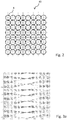
Comme illustré en
On connait aussi des capteurs dont les microlentilles ne sont pas alignés selon des lignes et des colonnes, mais forment un assemblage de petites matrices (par exemple 3 par 3) périodique. Un exemple est donné par le document
Or, de par la régularité du réseau de microlentilles 4, certains points de l'espace objet sont imagés par plus de deux pixels, tandis que certaines zones ne sont imagées par aucun pixel ou par un seul pixel. Ces zones sont des zones aveugles dans l'espace objet pour la reconstruction.However, by virtue of the regularity of the array of
La
La
On connait également de l'art antérieur, des caméras plénoptiques dont la matrice de microlentilles est rendue aléatoire en décalant chaque lentille latérallement. Un exemple est donné dans le document
Le pouvoir de résolution d'une caméra plénoptique, défini comme la distance minimale qui doit séparer deux points contigus pour qu'ils soient imagés sur des couples de pixels différents, dépend de la distribution des intersections dans l'espace objet. Les caméras plénoptiques de l'art antérieur ont donc une bonne résolution dans certains plans, en revanche, elles ont une mauvaise résolution globale dans l'espace.The resolving power of a plenoptic camera, defined as the minimum distance that must separate two contiguous points for them to be imaged on pairs of different pixels, depends on the distribution of intersections in object space. The plenoptic cameras of the prior art therefore have good resolution in certain planes, on the other hand, they have poor overall resolution in space.
Un but de l'invention est de proposer une caméra plénoptique ayant une meilleure résolution dans l'espace que les dispositifs de l'art antérieur.An aim of the invention is to provide a plenoptic camera having better spatial resolution than the devices of the prior art.
Ce but est atteint dans le cadre de la présente invention grâce à une caméra plénoptique comprenant un système optique qui reçoit de la lumière issue d'un champ objet dans lequel est un espace objet destiné à être traité via la caméra, un capteur photosensible matriciel qui est composé de pixels arrangés en lignes et colonnes et tel que chaque pixel reçoit la lumière d'un seul rayon lumineux via le système optique.This object is achieved in the context of the present invention thanks to a plenoptic camera comprising an optical system which receives light coming from an object field in which is an object space intended to be processed via the camera, a matrix photosensitive sensor which is composed of pixels arranged in rows and columns and such that each pixel receives the light of a single ray of light via the optical system.
Ladite camera a son optique qui comprend une optique de focalisation et un réseau d'éléments optiques qui sont positionnés dans un plan image situé entre l'optique de focalisation et le capteur photosensible.Said camera has its optics which comprises a focusing optic and an array of optical elements which are positioned in an image plane located between the focusing optic and the photosensitive sensor.
Chaque élément optique forme sur le capteur photosensible une image macropixel en faisant correspondre à chaque pixel son rayon lumineux associé.Each optical element forms a macropixel image on the photosensitive sensor by making its associated light ray correspond to each pixel.
Dans la caméra, les éléments optiques sont arrangés en lignes et en colonnes parallèles respectivement aux lignes et colonnes du capteur matriciel en formant les intersections dans le champ objet,In the camera, the optical elements are arranged in rows and columns parallel respectively to the rows and columns of the matrix sensor, forming the intersections in the object field,
Dans la caméra, la distance qui sépare deux lignes adjacentes du réseau d'éléments optiques et/ou la distance qui sépare deux colonnes adjacentes du réseau d'éléments optiques est irrégulière dans ledit réseau, cette distance étant distincte pour au moins deux paires de lignes adjacentes et/ou deux paires de colonnes adjacentes du réseau d'éléments optiques, l'irrégularité en distance de séparation permettant de minimiser la plus grande distance entre tout point de l'espace objet et la plus proche desdites intersections de ces rayons lumineux.In the camera, the distance which separates two adjacent lines of the network of optical elements and / or the distance which separates two adjacent columns of the network of optical elements is irregular in said network, this distance being distinct for at least two pairs of lines adjacent and / or two pairs of adjacent columns of the array of optical elements, the irregularity in separation distance making it possible to minimize the greatest distance between any point in object space and the closest to said intersections of these light rays.
La distances entre deux lignes adjacentes, respectivement deux colonnes, est dite irrégulière si on ne peut la déduire de la connaissance de toutes les autres distances entre lignes adjacentes, respectivement colonnes, ou bien s'il faut connaitre la distance entre au moins vingt lignes, respectivement vingt colonnes, adjacentes pour la déduire.The distance between two adjacent lines, respectively two columns, is said to be irregular if it cannot be deduced from the knowledge of all the other distances between adjacent lines, respectively columns, or if the distance between at least twenty lines must be known, respectively twenty columns, adjacent to deduce it.
Dans un mode de réalisation avantageux, la distance entre deux colonnes (respectivement lignes) est fixée aléatoirement, notamment en utilisant un tirage selon une loi uniforme sur un intervalle prédéterminé.In an advantageous embodiment, the distance between two columns (respectively rows) is fixed randomly, in particular by using a drawing according to a uniform law over a predetermined interval.
Il n'y a alors pas de périodicité observable dans l'agencement des colonnes (respectivement des lignes).There is then no observable periodicity in the arrangement of the columns (respectively of the rows).
On considère que la distance qui sépare deux colonnes (ou lignes) adjacentes du réseau d'éléments optiques est irrégulière à partir du moment où l'écart entre une valeur et la valeur moyenne est supérieur à 2% de la valeur moyenne (cette condition est néanmoins non suffisante).It is considered that the distance which separates two adjacent columns (or rows) of the array of optical elements is irregular from the moment when the difference between a value and the mean value is greater than 2% of the mean value (this condition is however not sufficient).
Par rapport à la configuration de l'art antérieur, dans laquelle les éléments optiques sont alignés en lignes et en colonnes régulièrement espacées ou sont disposés en matrice selon des motifs périodiques, il existe moins de points de l'espace objet qui seront imagés sur plus de deux pixels, mais plus de points de l'espace objet qui seront imagés sur au moins deux pixels. C'est cet espace objet qui est avantageusement traité via la caméra.Compared to the configuration of the prior art, in which the optical elements are aligned in regularly spaced rows and columns or are arrayed in periodic patterns, there are fewer points in object space that will be imaged over more by two pixels, but more points in model space that will be imaged on at least two pixels. It is this object space which is advantageously processed via the camera.
Comme il suffit qu'un point de l'espace objet soit imagé sur deux pixels pour déterminer sa position dans l'espace, l'invention permet donc d'améliorer la résolution de reconstruction tridimensionnelle d'une caméra plénoptique.Since it suffices for a point of the object space to be imaged over two pixels to determine its position in space, the invention therefore makes it possible to improve the resolution of three-dimensional reconstruction of a plenoptic camera.
En outre, les points de l'espace imagés sur au moins deux pixels sont répartis de manière plus homogène dans l'espace, ce qui permet d'avoir une meilleure résolution globale dans l'espace.In addition, the points of space imaged on at least two pixels are distributed more homogeneously in space, which makes it possible to have a better overall resolution in space.
D'une part, les rayons lumineux associés à leur pixel forment des intersections dans ledit espace objet et d'autre part l'optique est réalisée de façon à minimiser la plus grande distance entre tout point de l'espace objet et la plus proche desdites intersections de ces rayons lumineux.On the one hand, the light rays associated with their pixel form intersections in said object space and on the other hand the optics are made so as to minimize the greatest distance between any point in the object space and the closest to said intersections of these light rays.
L'invention est avantageusement complétée par les caractéristiques suivantes, prises individuellement ou en l'une quelconque de leurs combinaisons techniquement possibles.The invention is advantageously completed by the following characteristics, taken individually or in any of their technically possible combinations.
Ni la distance entre deux lignes adjacentes, ni la distance entre deux colonnes adjacentes n'est constante. Ainsi, dans cette réalisation, le réseau d'éléments optiques présente des irrégularités à la fois quant à la distance qui sépare deux lignes adjacentes du réseau et quant à la distance qui sépare deux colonnes adjacentes. Le fait que le réseau d'éléments optiques comporte des irrégularités dans deux directions permet encore d'améliorer la répartition des points de l'espace imagés sur plus de deux pixels.Neither the distance between two adjacent rows nor the distance between two adjacent columns is constant. Thus, in this embodiment, the array of optical elements exhibits irregularities both as regards the distance which separates two adjacent lines of the array and as regards the distance which separates two adjacent columns. The fact that the array of optical elements comprises irregularities in two directions further improves the distribution of the points of space imaged over more than two pixels.
La distance entre deux lignes adjacentes et/ou deux colonnes adjacentes peut par exemple être choisie de manière aléatoire. Préférentiellement cette distance est dans une gamme de valeurs comprise entre 95% et 105% d'une valeur moyenne. Les tests effectués par les inventeurs ont permis de déterminer que cette configuration permettait une résolution accrue de la caméra plénoptique.The distance between two adjacent rows and / or two adjacent columns can for example be chosen randomly. Preferably, this distance is in a range of values between 95% and 105% of an average value. The tests carried out by the inventors made it possible to determine that this configuration allowed an increased resolution of the plenoptic camera.
D'une part l'image macropixel formée sur le capteur photosensible s'étend sur au moins deux pixels dans la direction verticale et/ou dans la direction horizontale et d'autre part la distance irrégulière dans ledit réseau sépare deux lignes adjacentes du réseau d'éléments optiques en correspondance de leurs images macropixels d'au moins deux pixels dans la direction verticale et/ou sépare deux colonnes adjacentes du réseau d'éléments optiques en correspondance de leurs images macropixels d'au moins deux pixels dans la direction horizontale.On the one hand, the macropixel image formed on the photosensitive sensor extends over at least two pixels in the vertical direction and / or in the horizontal direction and on the other hand the irregular distance in said network separates two adjacent lines of the network d 'optical elements in correspondence of their macropixel images of at least two pixels in the vertical direction and / or separates two adjacent columns of the array of optical elements in correspondence of their macropixel images of at least two pixels in the horizontal direction.
Les éléments optiques sont des microlentilles ou des sténopés.Optical elements are microlenses or pinholes.
L'association entre rayon et pixel est choisie dynamiquement dans un ensemble d'associations possibles et permet d'obtenir une image ou plusieurs images du champ objet.The association between ray and pixel is dynamically chosen from a set of possible associations and makes it possible to obtain an image or more images of the object field.
Un ensemble d'éléments pilotables d'obturation positionné en regard des éléments optiques permet la sélection dynamique d'un rayon unique pour chaque pixel en permettant la sélection d'une association dans l'ensemble d'associations possibles, les images étant formées par les éléments optiques sur le détecteur et pouvant présenter des recouvrements.A set of controllable shutter elements positioned opposite the optical elements allows the dynamic selection of a single ray for each pixel by allowing the selection of an association from the set of possible associations, the images being formed by the optical elements on the detector and possibly having overlaps.
Ainsi, on conçoit d'abord une configuration d'éléments optiques, présentant éventuellement des recouvrements entre les macropixels, et on place, devant ou derrière le plan du réseau d'éléments optiques, un masque matriciel. En commandant l'état des cellules du masque matriciel, on modifie dynamiquement les rayons issus des éléments optiques afin de répartir les intersections dans l'espace.Thus, a configuration of optical elements is first designed, possibly having overlaps between the macropixels, and a matrix mask is placed in front of or behind the plane of the array of optical elements. By controlling the state of the cells of the matrix mask, the rays coming from the optical elements are dynamically modified in order to distribute the intersections in space.
L'association entre rayon et pixels est bi-univoque pour au moins 2 bandes spectrales, les associations correspondant à ces bandes spectrales différant pour au moins 1 pixels.The association between ray and pixels is one-to-one for at least 2 spectral bands, the associations corresponding to these spectral bands differing for at least 1 pixels.
Un ensemble d'éléments de filtrage chromatique positionné en regard des éléments optiques assure l'unicité du rayon correspondant à chaque pixel dans chacune des bandes spectrales, permettant d'obtenir une image ou plusieurs images du champ objet, les images formées par les éléments optiques sur le détecteur pouvant présenter des recouvrements.A set of chromatic filtering elements positioned opposite the optical elements ensures the uniqueness of the ray corresponding to each pixel in each of the spectral bands, making it possible to obtain one or more images of the object field, the images formed by the optical elements on the detector which may have overlaps.
Ainsi, on passe dynamiquement d'une configuration à une autre, en changeant la longueur d'onde de l'éclairage pour le faire correspondre à la longueur d'onde des filtres positionnés devant le réseau d'éléments optiques correspondant à la configuration voulue.Thus, one passes dynamically from one configuration to another, by changing the wavelength of the lighting to make it correspond to the wavelength of the filters positioned in front of the array of optical elements corresponding to the desired configuration.
En considérant la réalisation différemment, on peut prévoir que la caméra plénoptique comporte deux réseaux d'éléments optiques contenus dans un même plan, un filtre chromatique ne laissant passer que les longueurs d'ondes dans une première bande de fréquence étant positionné devant les éléments optiques du premier réseau, un filtre passe bande ne laissant passer que les longueurs d'ondes dans une seconde bande de fréquence différente de la première bande de fréquence étant positionné devant les éléments optiques du second réseau.Considering the embodiment differently, provision can be made for the plenoptic camera to include two arrays of optical elements contained in the same plane, a chromatic filter allowing only wavelengths in a first frequency band to pass, being positioned in front of the optical elements. of the first network, a band-pass filter allowing only the wavelengths in a second frequency band different from the first frequency band to pass, being positioned in front of the optical elements of the second network.
L'invention propose également un dispositif d'acquisition tridimensionnel, comportant une caméra plénoptique comme décrit plus haut et un calculateur configuré pour déterminer, à partir de l'image fournie et/ou d'une série d'images fournies par la caméra plénoptique, une distance entre un point du champ objet et la caméra plénoptique.The invention also proposes a three-dimensional acquisition device, comprising a plenoptic camera as described above and a computer configured to determine, from the image supplied and / or a series of images supplied by the plenoptic camera, a distance between a point in the object field and the plenoptic camera.
L'invention propose également un procédé de calibration d'une caméra plénoptique comme décrit plus haut, comportant des étapes consistant à :
- allumer un seul point du champ objet ;
- répertorier les pixels du capteur photosensible éclairés ;
- associer au point du champ objet les pixels du capteur photosensible éclairés ;
- répéter les étapes précédentes pour un échantillon de points du champ objet.
- light a single point of the object field;
- list the illuminated photosensitive sensor pixels;
- associating the illuminated photosensitive sensor pixels with the point of the object field;
- repeat the previous steps for a sample of points in the object field.
L'invention propose également l'utilisation d'un dispositif d'acquisition tridimensionnel comme décrit plus haut pour le contrôle de forme et en particulier pour le contrôle de la forme d'une aube de turbomachine.The invention also proposes the use of a three-dimensional acquisition device as described above for checking the shape and in particular for checking the shape of a turbomachine blade.
D'autres objectifs, caractéristiques et avantages sortiront de la description détaillée qui suit en référence aux dessins donnés à titre illustratif et non limitatif parmi lesquels :
- la
figure 1 , discutée plus haut, illustre une caméra plénoptique de l'art antérieur ; - la
figure 2 , discutée plus haut, est une vue de face d'un réseau de microlentilles de l'art antérieur ; - la
figure 3a , discutée plus haut, illustre la répartition dans l'espace objet des intersections des rayons pour une caméra plénoptique de l'art antérieur ; - la
figure 3b est un agrandissement de lafigure 3a , illustrant des distances des points d'intersection ; - la
figure 4 illustre une caméra plénoptique conforme à un mode de réalisation de l'invention ; - la
figure 5 est une vue de face d'un réseau de microlentilles conforme à un mode de réalisation de l'invention ; - la
figure 6a illustre la répartition dans l'espace objet des intersections des rayons pour une caméra plénoptique conforme à l'invention ; - la
figure 6b est un agrandissement de lafigure 6a , illustrant des distances réduites des points d'intersection par rapport à l'illustration de lafigure 3b ; - la
figure 7 illustre une caméra plénoptique comportant un masque matriciel conformément à un mode de réalisation de l'invention ; - la
figure 8 une caméra plénoptique comportant des filtres chromatiques conformément à un mode de réalisation de l'invention.
- the
figure 1 , discussed above, illustrates a plenoptic camera of the prior art; - the
figure 2 , discussed above, is a front view of an array of prior art microlenses; - the
figure 3a , discussed above, illustrates the distribution in object space of the intersections of the rays for a plenoptic camera of the prior art; - the
figure 3b is an enlargement of thefigure 3a , illustrating distances of intersection points; - the
figure 4 illustrates a plenoptic camera according to one embodiment of the invention; - the
figure 5 is a front view of an array of microlenses in accordance with one embodiment of the invention; - the
figure 6a illustrates the distribution in object space of the intersections of the rays for a plenoptic camera according to the invention; - the
figure 6b is an enlargement of thefigure 6a , illustrating reduced distances of the intersection points compared to the illustration of thefigure 3b ; - the
figure 7 illustrates a plenoptic camera comprising a matrix mask in accordance with one embodiment of the invention; - the
figure 8 a plenoptic camera comprising chromatic filters in accordance with one embodiment of the invention.
Comme illustré sur la
L'optique de focalisation 2 est classiquement une lentille optique ou une combinaison de lentilles optiques, qui reçoit de la lumière à partir d'objets placés dans un champ objet.The focusing
La caméra plénoptique 1 a ses éléments optiques 40 disposés dans un plan image F' de la caméra plénoptique entre l'optique de focalisation 2 et le capteur photosensible 3, et parallèle au capteur.The
Le capteur photosensible 3 est situé au niveau d'un plan référencé F" dans les exemples qui sont aux figures. Chaque élément optique 4 forme sur le capteur photosensible 3 une image de l'optique de focalisation 2.The
Comme illustré sur la
Le capteur photosensible 3 est matriciel en étant composé de pixels arrangés en lignes et colonnes et tel que chaque pixel reçoit la lumière d'un seul rayon lumineux via le système optique.The
L'image prise par le capteur photosensible 3 contient donc l'information suffisante pour former des images vues selon des points de vue différents. Le réseau d'éléments optiques 40 est placé à une faible distance (de l'ordre de 0,5 mm) du capteur photosensible 3.The image taken by the
Les éléments optiques 4 peuvent notamment être des microlentilles, ou des sténopés. Dans le cas où les éléments optiques 4 sont des microlentilles, celles-ci peuvent être sphériques ou avoir une forme plus complexe permettant une jonction entre deux microlentilles 4 adjacentes. Les microlentilles ont typiquement un diamètre de l'ordre d'une fraction de millimètre.The
Dans le cas où les éléments optiques 4 sont des sténopés, le réseau d'éléments optiques 40 est une surface plane opaque dans laquelle sont ménagés des trous de très faible diamètre, typiquement espacés de l'ordre d'une fraction de millimètre.In the case where the
Le capteur photosensible 3 capte la lumière reçue pour produire une image. Le capteur photosensible 3 est un capteur matriciel et typiquement une matrice CCD. Le capteur photosensible 3 est un composant électronique photosensible composé de photosites adaptés pour convertir un rayonnement électromagnétique (UV, visible ou IR) en un signal électrique analogique. Ce signal est ensuite numérisé par un convertisseur analogique-numérique pour obtenir une image numérique composée de pixels, chaque pixel correspondant à un photosite du capteur photosensible 3.The
Comme illustré sur la
Comme illustré sur la
Dans le cas où les éléments optiques 4 sont des microlentilles, le centre optique de la microlentille est le point d'intersection entre le plan de la microlentille et l'axe optique.In the case where the
Dans le cas où les éléments optiques 4 sont des sténopés, le centre optique du sténopé est le centre du trou.In the case where the
Dans un premier mode de réalisation, la distance entre deux lignes adjacentes n'est pas constante, tandis que la distance entre deux colonnes est constante, ou de façon alternative, la distance entre deux lignes adjacentes est constante, mais la distance entre deux colonnes n'est pas constante.In a first embodiment, the distance between two adjacent rows is not constant, while the distance between two columns is constant, or alternatively, the distance between two adjacent rows is constant, but the distance between two columns n is not constant.
Dans un second mode de réalisation, ni la distance entre deux lignes adjacentes, ni la distance entre deux colonnes adjacentes, ne sont constantes.In a second embodiment, neither the distance between two adjacent rows, nor the distance between two adjacent columns, are constant.
La distance entre deux lignes adjacentes et celle entre deux colonnes est typiquement inférieure au millimètre.The distance between two adjacent lines and that between two columns is typically less than a millimeter.
La distance entre deux lignes adjacentes et/ou celle entre deux colonnes adjacentes est typiquement choisie dans une gamme de valeur comprise entre + et - 5% d'une valeur moyenne.The distance between two adjacent rows and / or that between two adjacent columns is typically chosen from a range of values between + and - 5% of an average value.
Alternativement, la distance entre deux lignes adjacentes et/ou celle entre deux colonnes adjacentes est typiquement choisie dans une gamme de valeur comprise entre + et - 10% d'une valeur moyenne.Alternatively, the distance between two adjacent rows and / or that between two adjacent columns is typically chosen from a range of values between + and - 10% of an average value.
La distances entre deux lignes adjacentes, respectivement deux colonnes, est irrégulière si on ne peut pas la déduire de la connaissance de toutes les autres distances entre lignes adjacentes, respectivement colonnes, ou bien s'il faut connaitre la distance entre au moins vingt lignes, respectivement vingt colonnes, adjacentes pour la déduire.The distance between two adjacent lines, respectively two columns, is irregular if it cannot be deduced from knowing all the other distances between adjacent lines, respectively columns, or if the distance between at least twenty lines must be known, respectively twenty columns, adjacent to deduce it.
La distance entre deux lignes adjacentes et/ou entre deux colonnes adjacentes, peut par exemple être choisie de manière aléatoire. On entend par là que dans ce cas, la répartition des distances entre deux lignes adjacentes et/ou entre deux colonnes adjacentes ne possède aucune structure, régularité, ou règle de prédiction identifiable, autrement dit que la distance entre deux lignes adjacentes et/ou entre deux colonnes adjacentes est tirée au hasard. En effet, les tests effectués par les inventeurs ont permis de déterminer que cette configuration permettait une résolution de reconstruction tridimensionnelle accrue de la caméra plénoptique.The distance between two adjacent rows and / or between two adjacent columns can for example be chosen randomly. This is understood to mean that in this case, the distribution of the distances between two adjacent lines and / or between two adjacent columns does not have any identifiable structure, regularity, or rule of prediction, in other words that the distance between two adjacent lines and / or between two adjacent columns is drawn at random. In fact, the tests carried out by the inventors made it possible to determine that this configuration allowed an increased three-dimensional reconstruction resolution of the plenoptic camera.
La distance entre deux lignes adjacentes et/ou celle entre deux colonnes adjacentes est typiquement choisie aléatoirement dans une gamme de valeur comprise entre + et - 5% autour d'une valeur moyenne.The distance between two adjacent rows and / or that between two adjacent columns is typically chosen randomly from a range of values between + and - 5% around an average value.
Alternativement, la distance entre deux lignes adjacentes et/ou celle entre deux colonnes adjacentes est choisie aléatoirement dans une gamme de valeur comprise entre + et - 10% d'une valeur moyenne.Alternatively, the distance between two adjacent rows and / or that between two adjacent columns is chosen randomly from a range of values between + and - 10% of an average value.
Un mode de réalisation avantageux consiste donc à déterminer aléatoirement la distance entre deux colonnes (respectivement lignes), notamment en utilisant un tirage selon une loi uniforme sur un intervalle de valeurs prédéterminé. En d'autres termes, ladite distance est fonction d'une valeur aléatoire.An advantageous embodiment therefore consists in determining the distance between two columns (respectively rows) at random, in particular by using a drawing according to a uniform law over a predetermined interval of values. In other words, said distance is a function of a random value.
Un exemple concret de position irrégulière est à présent donné.A concrete example of an irregular position is now given.
On veut placer K colonnes de microlentilles de rayon R. On choisit la position P1 de la première colonne de façon arbitraire. Pour les K-1 autres microlentilles on tire aléatoirement une valeur V entre [0, δ] selon une loi uniforme et on place le centre de la lentille courante pour qu'il soit distant du centre de la lentille précédente de 2R+V. La distance entre deux lentilles ne peut être déduite de la distance entre les autres lentilles car elle dépend de la variable aléatoire V tirée uniformément sur le voisinage [0, δ].We want to place K columns of microlenses of radius R. We choose the position P1 of the first column arbitrarily. For the other K-1 microlenses, a value V is drawn randomly between [0, δ] according to a uniform law and the center of the current lens is placed so that it is distant from the center of the previous lens by 2R + V. The distance between two lenses cannot be deduced from the distance between the other lenses because it depends on the random variable V drawn uniformly on the neighborhood [0, δ].
Il n'y a alors pas de périodicité observable dans l'agencement des colonnes (respectivement des lignes).There is then no observable periodicity in the arrangement of the columns (respectively of the rows).
La
Par rapport à une configuration dans laquelle les éléments optiques sont alignés en lignes et en colonnes régulièrement espacées, il existe moins de points de l'espace objet qui seront imagés sur plus de deux pixels, mais plus de points de l'espace objet qui seront imagés sur au moins deux pixels.Compared to a configuration in which the optical elements are aligned in regularly spaced rows and columns, there are fewer model space points that will be imaged over two pixels, but more model space points that will be. imaged on at least two pixels.
Comme il suffit qu'un point de l'espace objet soit imagé sur deux pixels pour pouvoir déterminer sa position dans l'espace, l'invention permet donc d'améliorer la résolution de reconstruction tridimensionnelle d'une caméra plénoptique.Since it is sufficient for a point of the object space to be imaged on two pixels to be able to determine its position in space, the invention therefore makes it possible to improve the resolution of three-dimensional reconstruction of a plenoptic camera.
La
La disposition des éléments optiques 4 est avantageusement modifiée de façon dynamique pour pouvoir s'adapter à des situations particulières.The arrangement of the
En effet, la disposition des éléments optiques 4 détermine le positionnement des intersections, et donc la résolution de la mesure tridimensionnelle dans l'espace. On choisira donc la configuration du réseau d'éléments optiques 40 en fonction de la répartition des intersections recherchée. Notamment, une configuration peut générer une forte concentration d'intersections dans une zone particulière de l'espace et sera particulièrement intéressante pour acquérir un objet contenu dans cette zone de l'espace.Indeed, the arrangement of the
Avantageusement, le système optique traite la lumière issue du champ objet dans lequel est l'espace objet traité via la caméra. D'une part les rayons lumineux associés à chacun à leur pixel forment des intersections dans ledit espace objet et d'autre part l'optique est réalisée de façon à minimiser la plus grande distance entre tout point de l'espace objet et la plus proche desdites intersections de ces rayons lumineux.Advantageously, the optical system processes the light coming from the object field in which the object space is processed via the camera. On the one hand, the light rays associated with each one with their pixel form intersections in said object space and on the other hand the optics are produced so as to minimize the greatest distance between any point in the object space and the closest of said intersections of these light rays.
Chaque élément optique 4 forme sur le capteur photosensible 3 une image macropixel s'étendant sur au moins deux pixels dans la direction verticale et/ou dans la direction horizontale en faisant correspondre à chaque pixel son rayon lumineux associé. Les éléments optiques 4 sont alignés arrangés en lignes et en colonnes parallèles respectivement aux lignes et colonnes du capteur matriciel 3 en formant les intersections dans le champ objet.Each
La distance qui sépare deux lignes adjacentes du réseau d'éléments optiques en correspondance de leurs images macropixels d'au moins deux pixels dans la direction verticale et/ou la distance qui sépare deux colonnes adjacentes du réseau d'éléments optiques en correspondance de leurs images macropixels d'au moins deux pixels dans la direction horizontale est irrégulière dans ledit réseau. Cette irrégularité dans lesdites distances séparant lesdites lignes et/ou colonnes permet de minimiser la plus grande distance entre tout point de l'espace objet et la plus proche desdites intersections de ces rayons lumineux,The distance between two adjacent lines of the array of optical elements in correspondence of their macropixel images of at least two pixels in the vertical direction and / or the distance between two adjacent columns of the array of optical elements in correspondence of their images macropixels of at least two pixels in the horizontal direction is irregular in said grating. This irregularity in said distances separating said rows and / or columns makes it possible to minimize the greatest distance between any point in object space and the closest to said intersections of these light rays,
Pour modifier la configuration des éléments optiques 4, on peut déplacer les éléments optiques 4. Un déplacement des éléments optiques 4 peut notamment être obtenu à l'aide d'actionneurs adaptés pour déplacer indépendamment chaque élément optique 4.To modify the configuration of the
On peut aussi utiliser un masque matriciel 50 positionné devant ou derrière le réseau d'éléments optiques 40, comme illustré sur la
Ainsi, on conçoit d'abord une configuration d'éléments optiques 4, présentant éventuellement des recouvrements entre les macropixels, et on place, devant ou derrière le plan du réseau d'éléments optiques 40, un masque matriciel 50.Thus, a configuration of
En commandant l'état des cellules du masque matriciel 50, on modifie dynamiquement les rayons issus des éléments optiques 40 afin d'interdire à plus d'un rayon de parvenir sur chaque pixel et de répartir les intersections dans l'espace.By controlling the state of the cells of the
En combinant les images obtenues pour plusieurs états du masquage, on enrichit l'ensemble des intersections des rayons et on améliore la résolution de reconstruction tridimensionnelle.By combining the images obtained for several masking states, the set of intersections of the rays is enriched and the resolution of three-dimensional reconstruction is improved.
Avantageusement, l'association entre rayon et pixel est choisie dynamiquement dans un ensemble d'associations possibles et permet d'obtenir une image ou plusieurs images du champ objet.Advantageously, the association between ray and pixel is dynamically chosen from a set of possible associations and makes it possible to obtain an image or more images of the object field.
Avantageusement, il peut être prévu un ensemble d'éléments pilotables d'obturation positionné en regard des éléments optiques 4 de manière à permettre la sélection dynamique d'un rayon unique pour chaque pixel en permettant la sélection d'une association dans l'ensemble d'associations possibles. Les images étant formées par les éléments optiques 4 sur le détecteur 3, elles peuvent présenter des recouvrements,Advantageously, there can be provided a set of controllable shutter elements positioned opposite the
Une autre façon de changer dynamiquement la géométrie des éléments optiques 4 est de positionner, comme illustré sur la
Avantageusement, l'association entre rayon et pixels est bi-univoque pour au moins 2 bandes spectrales, les associations correspondant à ces bandes spectrales différant pour au moins 1 pixels.Advantageously, the association between ray and pixels is one-to-one for at least 2 spectral bands, the associations corresponding to these spectral bands differing for at least 1 pixels.
Ainsi, on conçoit d'abord deux configurations (ou plus) d'éléments optiques 4, présentant éventuellement des recouvrements entre les macropixels, et on passe dynamiquement d'une configuration à une autre, en changeant la longueur d'onde de la lumière issue du champ objet pour la faire correspondre à la longueur d'onde des filtres de la configuration voulue.Thus, one first conceives two configurations (or more) of
Avantageusement, il peut être prévu qu'un ensemble d'éléments de filtrage chromatique soit positionné en regard des éléments optiques 4 assure l'unicité du rayon correspondant à chaque pixel dans chacune des bandes spectrales, permettant d'obtenir une image ou plusieurs images du champ objet, les images formées par les éléments optiques 4 sur le détecteur 3 pouvant présenter des recouvrements.Advantageously, provision can be made for a set of chromatic filtering elements to be positioned opposite the
A cours d'une étape de calibration, on détermine, pour chaque point du champ objet, les pixels sur lequel le point du champ objet est imagé. On associe à chaque point du champ objet, les pixels sur lequel ledit point du champ objet est imagé. Pour pouvoir déterminer les coordonnées 3D d'un point du champ objet, il faut au minimum que le point du champ objet soit imagé sur deux pixels différents.During a calibration step, one determines, for each point of the object field, the pixels on which the point of the object field is imaged. We associate with each point of the object field, the pixels on which said point of the object field is imaged. To be able to determine the 3D coordinates of a point in the object field, the point in the object field must at least be imaged on two different pixels.
Notamment, on peut effectuer la calibration en allumant un seul point du champ objet à la fois et en répertoriant les pixels du capteur photosensible 3 éclairés, et ce pour un échantillon de points de l'espace objet correspondant à la résolution souhaitée.In particular, the calibration can be carried out by lighting a single point of the object field at a time and by listing the pixels of the
A cet effet, on positionne un écran dans un plan normal à la direction d'observation de la caméra 1, et déplace progressivement cet écran vers le capteur 3, par pas inférieurs à la résolution en distance recherchée.To this end, a screen is positioned in a plane normal to the direction of observation of the
Pour chaque position de cet écran, donc pour chaque distance à la caméra 1, on allume sélectivement chaque point de l'écran tour à tour. Pour chaque point de l'écran, on détermine au moins les deux pixels du capteur 3 les plus éclairés. Si leur niveau d'éclairement est suffisant, en pratique supérieur à un seuil choisi, on associe le point au couple de pixels éclairés. On crée ainsi une table associant à un point du champ objet le couple de pixels du capteur photosensible 2 sur lequel ledit point est imagé.For each position of this screen, therefore for each distance from
Un dispositif d'acquisition tridimensionnel, comporte une caméra plénoptique 1, et un calculateur 5 configuré pour déterminer, à partir de l'image fournie ou de l'ensemble d'images fournies par le capteur photosensible 3, une distance entre un point du champ objet et la caméra plénoptique 1.A three-dimensional acquisition device, comprises a
Le calculateur 5 est configuré pour mettre en œuvre des étapes d'association et de reconstruction tridimensionnelle comme décrit ci-dessous.The
A cours d'une étape d'association, le calculateur 5 associe entre eux les pixels différents qui correspondent au même point du champ objet. C'est cela qui permet la détermination des coordonnées 3D des points de la scène par triangulation.During an association step, the
Les pixels différents qui correspondent au même point du champ objet sont associés de façon classique.The different pixels which correspond to the same point of the object field are associated in a conventional manner.
A cours d'une étape de reconstruction tridimensionnelle, le calculateur 5 détermine, par triangulation, les coordonnées 3D des points du champ objet à partir des associations faites et des paramètres de calibration de la caméra plénoptique 1. Les points visibles sur les images étant les projections du point du champ objet, la position dans l'espace du point du champ objet est obtenue par intersection des rayons lumineux associés aux pixels images du point de champ objet.During a three-dimensional reconstruction step, the
Claims (14)
- A plenoptic camera (1) comprising an optical system which receives light from an object field in which an object space is intended to be processed via the camera, a photosensitive matrix sensor (3) which is composed of pixels arranged in rows and columns and such that each pixel receives the light from a single light ray via the optical system, wherein:- its optical system comprises focusing optics (2) ;- its optical system comprises an array (40) of optical elements (4) which are positioned in an image plane (F') located between the focusing optics (2) and the photosensitive sensor (3);- each optical element (4) forms on the photosensitive sensor (3) a macropixel image by matching each pixel to its associated light ray;- and wherein the optical elements have an irregular structureand characterized in that:- the optical elements (4) are arranged in rows and in columns parallel respectively to the rows and columns of the matrix sensor (3) by forming the intersections in the object field;- the distance which separates two adjacent rows of the array of optical elements and/or the distance which separates two adjacent columns of the array of optical elements is irregular in said array, this distance being distinct for at least two pairs of adjacent rows and/or two pairs of adjacent columns of the array of optical elements.
- The plenoptic camera (1) according to the preceding claim, wherein the array of optical elements has irregularities both as to the distance which separates two adjacent rows of the array and as to the distance which separates two adjacent columns.
- The plenoptic camera according to any one of the preceding claims, wherein the distance between two adjacent columns, respectively rows, is a function of a random value, preferably using a draw of a random value according to a uniform law over a predetermined range of values.
- The plenoptic camera (1) according to one of claims 1 to 3, wherein on the one hand, the macropixel image formed on the photosensitive sensor (3) extends over at least two pixels in the vertical direction and/or in the horizontal direction and on the other hand, the irregular distance in said array separates two adjacent rows of the array of optical elements in correspondence with their macropixel images of at least two pixels in the vertical direction and/or separates two adjacent columns of the array of optical elements in correspondence with their macropixel images of at least two pixels in the horizontal direction.
- The plenoptic camera (1) according to one of claims 1 to 4, wherein the distance between two adjacent rows and/or two adjacent columns is randomly selected.
- The plenoptic camera (1) according to one of claims 1 to 5, wherein the distance between two adjacent rows and/or two adjacent columns is randomly selected in a range of values comprised between 95% and 105% of a mean value.
- The plenoptic camera (1) according to one of claims 1 to 6, wherein the optical elements (4) are microlenses.
- The plenoptic camera (1) according to one of claims 1 to 6, wherein the optical elements (4) are pinholes.
- The plenoptic camera (1) according to claim 1, wherein the association between a ray and a pixel is dynamically selected in a set of possible associations and makes it possible to obtain one image or several images of the object field.
- The plenoptic camera (1) according to claim 9, wherein a set of controllable shutter elements positioned facing the optical elements (4) allows the dynamic selection of a single ray for each pixel by allowing the selection of an association in the set of possible associations, the images being formed by the optical elements (4) on the detector (3) and being able to have overlaps.
- The plenoptic camera (1) according to claim 1, wherein the association between a ray and pixels is one-to-one for at least two spectral bands, the associations corresponding to those spectral bands differing for at least one pixel.
- The plenoptic camera (1) according to claim 11 and any one of the preceding claims, wherein a set of chromatic filter elements positioned facing the optical elements (4) ensures the uniqueness of the ray corresponding to each pixel in each of the spectral bands, allowing to obtain one image or several images of the object field, the images formed by the optical elements (4) on the detector (3) possibly having overlaps.
- A three-dimensional acquisition device, including a plenoptic camera (1) according to one of the preceding claims, and a calculator (5) configured to determine, from the provided image and/or a series of images provided by the plenoptic camera (1), a distance between a point of the object field and the plenoptic camera (1).
- A method for calibrating a plenoptic camera (1) according to one of claims 1 to 12, including steps of:- lighting a single point of the object field;- listing the illuminated pixels of the photosensitive sensor (3);- associating the illuminated pixels of the photosensitive sensor (3) with the point of the object field;- repeating the preceding steps for a sample of points of the object field.
Applications Claiming Priority (2)
| Application Number | Priority Date | Filing Date | Title |
|---|---|---|---|
| FR1558338A FR3040798B1 (en) | 2015-09-08 | 2015-09-08 | PLENOPTIC CAMERA |
| PCT/FR2016/052242 WO2017042494A1 (en) | 2015-09-08 | 2016-09-08 | Plenoptic camera |
Publications (2)
| Publication Number | Publication Date |
|---|---|
| EP3348048A1 EP3348048A1 (en) | 2018-07-18 |
| EP3348048B1 true EP3348048B1 (en) | 2020-10-28 |
Family
ID=54329816
Family Applications (1)
| Application Number | Title | Priority Date | Filing Date |
|---|---|---|---|
| EP16785184.9A Active EP3348048B1 (en) | 2015-09-08 | 2016-09-08 | Plenoptic camera |
Country Status (4)
| Country | Link |
|---|---|
| US (1) | US10778874B2 (en) |
| EP (1) | EP3348048B1 (en) |
| FR (1) | FR3040798B1 (en) |
| WO (1) | WO2017042494A1 (en) |
Families Citing this family (5)
| Publication number | Priority date | Publication date | Assignee | Title |
|---|---|---|---|---|
| FR3051584B1 (en) | 2016-05-20 | 2019-11-01 | Safran | METHOD FOR THREE DIMENSIONAL RECONSTRUCTION USING A PLENOPTIC CAMERA |
| CN107767440B (en) * | 2017-09-06 | 2021-01-26 | 北京建筑大学 | Cultural relic sequence image fine three-dimensional reconstruction method based on triangulation network interpolation and constraint |
| FR3115626A1 (en) | 2020-10-26 | 2022-04-29 | Safran | Process for calibrating a plenoptic camera |
| CN114167622A (en) * | 2021-12-14 | 2022-03-11 | 樊宸 | Optical system for acquiring three-dimensional information of surface of shot object |
| FR3132968A1 (en) | 2022-02-22 | 2023-08-25 | Safran | Process for calibrating a plenoptic camera |
Family Cites Families (12)
| Publication number | Priority date | Publication date | Assignee | Title |
|---|---|---|---|---|
| US20060192869A1 (en) * | 2005-02-28 | 2006-08-31 | Kazutora Yoshino | Multi-dimensional input, transfer, optional memory, and output method |
| US7671321B2 (en) * | 2005-01-18 | 2010-03-02 | Rearden, Llc | Apparatus and method for capturing still images and video using coded lens imaging techniques |
| ATE551841T1 (en) * | 2009-04-22 | 2012-04-15 | Raytrix Gmbh | DIGITAL IMAGING METHOD FOR SYNTHESIZING AN IMAGE USING DATA RECORDED BY A PLENOPTIC CAMERA |
| KR101300733B1 (en) * | 2012-01-12 | 2013-08-27 | 연세대학교 산학협력단 | multi parallel confocal systeme |
| JP5963448B2 (en) * | 2012-01-13 | 2016-08-03 | キヤノン株式会社 | Imaging device |
| JP5836821B2 (en) * | 2012-01-30 | 2015-12-24 | オリンパス株式会社 | Imaging device |
| GB2501936B (en) * | 2012-05-11 | 2016-11-30 | Canon Kk | Micro lens array and imaging apparatus |
| JP2015060121A (en) * | 2013-09-19 | 2015-03-30 | 株式会社東芝 | Color filter array and solid-state imaging element |
| JP6417809B2 (en) * | 2014-03-05 | 2018-11-07 | ソニー株式会社 | Imaging device |
| US9544583B2 (en) * | 2015-01-09 | 2017-01-10 | Ricoh Company, Ltd. | Object space calibration of plenoptic imaging systems |
| FR3051584B1 (en) * | 2016-05-20 | 2019-11-01 | Safran | METHOD FOR THREE DIMENSIONAL RECONSTRUCTION USING A PLENOPTIC CAMERA |
| US10757390B2 (en) * | 2016-08-05 | 2020-08-25 | Interdigital Ce Patent Holdings | Method for obtaining at least one sub-aperture image being associated with one view |
-
2015
- 2015-09-08 FR FR1558338A patent/FR3040798B1/en active Active
-
2016
- 2016-09-08 WO PCT/FR2016/052242 patent/WO2017042494A1/en active Application Filing
- 2016-09-08 EP EP16785184.9A patent/EP3348048B1/en active Active
- 2016-09-08 US US15/758,111 patent/US10778874B2/en active Active
Non-Patent Citations (1)
| Title |
|---|
| None * |
Also Published As
| Publication number | Publication date |
|---|---|
| US20180249050A1 (en) | 2018-08-30 |
| EP3348048A1 (en) | 2018-07-18 |
| WO2017042494A1 (en) | 2017-03-16 |
| FR3040798B1 (en) | 2018-02-09 |
| US10778874B2 (en) | 2020-09-15 |
| FR3040798A1 (en) | 2017-03-10 |
Similar Documents
| Publication | Publication Date | Title |
|---|---|---|
| EP3348048B1 (en) | Plenoptic camera | |
| FR3065132B1 (en) | DEVICE AND METHOD FOR MULTISPECTRAL IMAGING IN THE INFRARED | |
| EP3459051B1 (en) | Three-dimensional reconstruction method using a plenoptic camera | |
| FR2994602A1 (en) | SPECTRAL FILTERING DEVICE IN VISIBLE AND INFRARED DOMAINS | |
| FR2969819A1 (en) | THREE DIMENSIONAL IMAGE SENSOR | |
| FR3007534A1 (en) | PRODUCTION OF A NANOSTRUCTURE SPECTRAL FILTER | |
| EP2681604A2 (en) | High-resolution imaging system | |
| EP2846357A1 (en) | Photodetector device with semiconductor regions divided by a potential barrier | |
| FR2940720A1 (en) | IMAGE ENTRY DEVICE COMPRISING FOCUS CORRECTION MEANS | |
| WO2021156581A1 (en) | Device for observing a star | |
| CA3029532A1 (en) | Fourier transform multi-channel spectral imager | |
| FR3026227A1 (en) | DEVICE FOR ACQUIRING 3D IMAGES | |
| FR3102845A1 (en) | Determination of at least one optical parameter of an optical lens | |
| EP3516353B1 (en) | Method for improving the detection capacities of a multispectral imaging system | |
| FR2755337A1 (en) | CAMERA SYSTEM | |
| FR3101420A1 (en) | Method for evaluating the optical quality of a delimited area of a glazing | |
| EP2093602A1 (en) | Imaging device with deflectors | |
| EP3688808B1 (en) | Resizing of detection entities of a hybrid matrix image sensor | |
| FR3050833B1 (en) | PLENOPTIC CAMERA WITH CORRECTION OF GEOMETRIC ABERRATIONS | |
| EP3165875B1 (en) | Method for acquiring images by a spaceborne or airborne optical instrument with extended field of view | |
| WO2021019136A1 (en) | Device for inspecting a surface of an object | |
| WO2022129721A1 (en) | Method for inspecting a surface of an object | |
| FR2690533A1 (en) | Image sensor for electronic image capture devices - has set of objective lenses forming images on matrix of photodetectors e.g. CCDs | |
| FR2860119A1 (en) | Object scenes representation producing device for monitoring surroundings of e.g. aircraft, has filtering unit arranged in intermediate image plane and having two color frames with two different filtering characteristics | |
| CA3086228A1 (en) | Method and system for imaging at high and low light levels |
Legal Events
| Date | Code | Title | Description |
|---|---|---|---|
| STAA | Information on the status of an ep patent application or granted ep patent |
Free format text: STATUS: UNKNOWN |
|
| STAA | Information on the status of an ep patent application or granted ep patent |
Free format text: STATUS: THE INTERNATIONAL PUBLICATION HAS BEEN MADE |
|
| PUAI | Public reference made under article 153(3) epc to a published international application that has entered the european phase |
Free format text: ORIGINAL CODE: 0009012 |
|
| STAA | Information on the status of an ep patent application or granted ep patent |
Free format text: STATUS: REQUEST FOR EXAMINATION WAS MADE |
|
| 17P | Request for examination filed |
Effective date: 20180330 |
|
| AK | Designated contracting states |
Kind code of ref document: A1 Designated state(s): AL AT BE BG CH CY CZ DE DK EE ES FI FR GB GR HR HU IE IS IT LI LT LU LV MC MK MT NL NO PL PT RO RS SE SI SK SM TR |
|
| AX | Request for extension of the european patent |
Extension state: BA ME |
|
| DAV | Request for validation of the european patent (deleted) | ||
| DAX | Request for extension of the european patent (deleted) | ||
| REG | Reference to a national code |
Ref country code: DE Ref legal event code: R079 Ref document number: 602016046774 Country of ref document: DE Free format text: PREVIOUS MAIN CLASS: H04N0005225000 Ipc: H04N0013232000 |
|
| RIC1 | Information provided on ipc code assigned before grant |
Ipc: H04N 5/225 20060101ALI20200330BHEP Ipc: H04N 13/232 20180101AFI20200330BHEP Ipc: G03B 35/08 20060101ALI20200330BHEP |
|
| GRAP | Despatch of communication of intention to grant a patent |
Free format text: ORIGINAL CODE: EPIDOSNIGR1 |
|
| STAA | Information on the status of an ep patent application or granted ep patent |
Free format text: STATUS: GRANT OF PATENT IS INTENDED |
|
| INTG | Intention to grant announced |
Effective date: 20200511 |
|
| RIN1 | Information on inventor provided before grant (corrected) |
Inventor name: LE GUILLOUX, YANN Inventor name: PICARD, SYLVAINE |
|
| GRAS | Grant fee paid |
Free format text: ORIGINAL CODE: EPIDOSNIGR3 |
|
| GRAA | (expected) grant |
Free format text: ORIGINAL CODE: 0009210 |
|
| STAA | Information on the status of an ep patent application or granted ep patent |
Free format text: STATUS: THE PATENT HAS BEEN GRANTED |
|
| AK | Designated contracting states |
Kind code of ref document: B1 Designated state(s): AL AT BE BG CH CY CZ DE DK EE ES FI FR GB GR HR HU IE IS IT LI LT LU LV MC MK MT NL NO PL PT RO RS SE SI SK SM TR |
|
| REG | Reference to a national code |
Ref country code: GB Ref legal event code: FG4D Free format text: NOT ENGLISH |
|
| REG | Reference to a national code |
Ref country code: CH Ref legal event code: EP |
|
| REG | Reference to a national code |
Ref country code: AT Ref legal event code: REF Ref document number: 1329438 Country of ref document: AT Kind code of ref document: T Effective date: 20201115 |
|
| REG | Reference to a national code |
Ref country code: DE Ref legal event code: R096 Ref document number: 602016046774 Country of ref document: DE |
|
| REG | Reference to a national code |
Ref country code: IE Ref legal event code: FG4D Free format text: LANGUAGE OF EP DOCUMENT: FRENCH |
|
| REG | Reference to a national code |
Ref country code: AT Ref legal event code: MK05 Ref document number: 1329438 Country of ref document: AT Kind code of ref document: T Effective date: 20201028 |
|
| REG | Reference to a national code |
Ref country code: NL Ref legal event code: MP Effective date: 20201028 |
|
| PG25 | Lapsed in a contracting state [announced via postgrant information from national office to epo] |
Ref country code: NO Free format text: LAPSE BECAUSE OF FAILURE TO SUBMIT A TRANSLATION OF THE DESCRIPTION OR TO PAY THE FEE WITHIN THE PRESCRIBED TIME-LIMIT Effective date: 20210128 Ref country code: RS Free format text: LAPSE BECAUSE OF FAILURE TO SUBMIT A TRANSLATION OF THE DESCRIPTION OR TO PAY THE FEE WITHIN THE PRESCRIBED TIME-LIMIT Effective date: 20201028 Ref country code: PT Free format text: LAPSE BECAUSE OF FAILURE TO SUBMIT A TRANSLATION OF THE DESCRIPTION OR TO PAY THE FEE WITHIN THE PRESCRIBED TIME-LIMIT Effective date: 20210301 Ref country code: GR Free format text: LAPSE BECAUSE OF FAILURE TO SUBMIT A TRANSLATION OF THE DESCRIPTION OR TO PAY THE FEE WITHIN THE PRESCRIBED TIME-LIMIT Effective date: 20210129 Ref country code: FI Free format text: LAPSE BECAUSE OF FAILURE TO SUBMIT A TRANSLATION OF THE DESCRIPTION OR TO PAY THE FEE WITHIN THE PRESCRIBED TIME-LIMIT Effective date: 20201028 |
|
| REG | Reference to a national code |
Ref country code: LT Ref legal event code: MG4D |
|
| PG25 | Lapsed in a contracting state [announced via postgrant information from national office to epo] |
Ref country code: SE Free format text: LAPSE BECAUSE OF FAILURE TO SUBMIT A TRANSLATION OF THE DESCRIPTION OR TO PAY THE FEE WITHIN THE PRESCRIBED TIME-LIMIT Effective date: 20201028 Ref country code: ES Free format text: LAPSE BECAUSE OF FAILURE TO SUBMIT A TRANSLATION OF THE DESCRIPTION OR TO PAY THE FEE WITHIN THE PRESCRIBED TIME-LIMIT Effective date: 20201028 Ref country code: AT Free format text: LAPSE BECAUSE OF FAILURE TO SUBMIT A TRANSLATION OF THE DESCRIPTION OR TO PAY THE FEE WITHIN THE PRESCRIBED TIME-LIMIT Effective date: 20201028 Ref country code: BG Free format text: LAPSE BECAUSE OF FAILURE TO SUBMIT A TRANSLATION OF THE DESCRIPTION OR TO PAY THE FEE WITHIN THE PRESCRIBED TIME-LIMIT Effective date: 20210128 Ref country code: PL Free format text: LAPSE BECAUSE OF FAILURE TO SUBMIT A TRANSLATION OF THE DESCRIPTION OR TO PAY THE FEE WITHIN THE PRESCRIBED TIME-LIMIT Effective date: 20201028 Ref country code: IS Free format text: LAPSE BECAUSE OF FAILURE TO SUBMIT A TRANSLATION OF THE DESCRIPTION OR TO PAY THE FEE WITHIN THE PRESCRIBED TIME-LIMIT Effective date: 20210228 Ref country code: LV Free format text: LAPSE BECAUSE OF FAILURE TO SUBMIT A TRANSLATION OF THE DESCRIPTION OR TO PAY THE FEE WITHIN THE PRESCRIBED TIME-LIMIT Effective date: 20201028 |
|
| PG25 | Lapsed in a contracting state [announced via postgrant information from national office to epo] |
Ref country code: NL Free format text: LAPSE BECAUSE OF FAILURE TO SUBMIT A TRANSLATION OF THE DESCRIPTION OR TO PAY THE FEE WITHIN THE PRESCRIBED TIME-LIMIT Effective date: 20201028 Ref country code: HR Free format text: LAPSE BECAUSE OF FAILURE TO SUBMIT A TRANSLATION OF THE DESCRIPTION OR TO PAY THE FEE WITHIN THE PRESCRIBED TIME-LIMIT Effective date: 20201028 |
|
| REG | Reference to a national code |
Ref country code: DE Ref legal event code: R097 Ref document number: 602016046774 Country of ref document: DE |
|
| PG25 | Lapsed in a contracting state [announced via postgrant information from national office to epo] |
Ref country code: LT Free format text: LAPSE BECAUSE OF FAILURE TO SUBMIT A TRANSLATION OF THE DESCRIPTION OR TO PAY THE FEE WITHIN THE PRESCRIBED TIME-LIMIT Effective date: 20201028 Ref country code: SM Free format text: LAPSE BECAUSE OF FAILURE TO SUBMIT A TRANSLATION OF THE DESCRIPTION OR TO PAY THE FEE WITHIN THE PRESCRIBED TIME-LIMIT Effective date: 20201028 Ref country code: CZ Free format text: LAPSE BECAUSE OF FAILURE TO SUBMIT A TRANSLATION OF THE DESCRIPTION OR TO PAY THE FEE WITHIN THE PRESCRIBED TIME-LIMIT Effective date: 20201028 Ref country code: EE Free format text: LAPSE BECAUSE OF FAILURE TO SUBMIT A TRANSLATION OF THE DESCRIPTION OR TO PAY THE FEE WITHIN THE PRESCRIBED TIME-LIMIT Effective date: 20201028 Ref country code: SK Free format text: LAPSE BECAUSE OF FAILURE TO SUBMIT A TRANSLATION OF THE DESCRIPTION OR TO PAY THE FEE WITHIN THE PRESCRIBED TIME-LIMIT Effective date: 20201028 Ref country code: RO Free format text: LAPSE BECAUSE OF FAILURE TO SUBMIT A TRANSLATION OF THE DESCRIPTION OR TO PAY THE FEE WITHIN THE PRESCRIBED TIME-LIMIT Effective date: 20201028 |
|
| PG25 | Lapsed in a contracting state [announced via postgrant information from national office to epo] |
Ref country code: DK Free format text: LAPSE BECAUSE OF FAILURE TO SUBMIT A TRANSLATION OF THE DESCRIPTION OR TO PAY THE FEE WITHIN THE PRESCRIBED TIME-LIMIT Effective date: 20201028 |
|
| PLBE | No opposition filed within time limit |
Free format text: ORIGINAL CODE: 0009261 |
|
| STAA | Information on the status of an ep patent application or granted ep patent |
Free format text: STATUS: NO OPPOSITION FILED WITHIN TIME LIMIT |
|
| 26N | No opposition filed |
Effective date: 20210729 |
|
| PG25 | Lapsed in a contracting state [announced via postgrant information from national office to epo] |
Ref country code: AL Free format text: LAPSE BECAUSE OF FAILURE TO SUBMIT A TRANSLATION OF THE DESCRIPTION OR TO PAY THE FEE WITHIN THE PRESCRIBED TIME-LIMIT Effective date: 20201028 Ref country code: IT Free format text: LAPSE BECAUSE OF FAILURE TO SUBMIT A TRANSLATION OF THE DESCRIPTION OR TO PAY THE FEE WITHIN THE PRESCRIBED TIME-LIMIT Effective date: 20201028 |
|
| PG25 | Lapsed in a contracting state [announced via postgrant information from national office to epo] |
Ref country code: SI Free format text: LAPSE BECAUSE OF FAILURE TO SUBMIT A TRANSLATION OF THE DESCRIPTION OR TO PAY THE FEE WITHIN THE PRESCRIBED TIME-LIMIT Effective date: 20201028 |
|
| REG | Reference to a national code |
Ref country code: CH Ref legal event code: PL |
|
| REG | Reference to a national code |
Ref country code: BE Ref legal event code: MM Effective date: 20210930 |
|
| PG25 | Lapsed in a contracting state [announced via postgrant information from national office to epo] |
Ref country code: IS Free format text: LAPSE BECAUSE OF FAILURE TO SUBMIT A TRANSLATION OF THE DESCRIPTION OR TO PAY THE FEE WITHIN THE PRESCRIBED TIME-LIMIT Effective date: 20210228 Ref country code: MC Free format text: LAPSE BECAUSE OF FAILURE TO SUBMIT A TRANSLATION OF THE DESCRIPTION OR TO PAY THE FEE WITHIN THE PRESCRIBED TIME-LIMIT Effective date: 20201028 |
|
| PG25 | Lapsed in a contracting state [announced via postgrant information from national office to epo] |
Ref country code: LU Free format text: LAPSE BECAUSE OF NON-PAYMENT OF DUE FEES Effective date: 20210908 Ref country code: IE Free format text: LAPSE BECAUSE OF NON-PAYMENT OF DUE FEES Effective date: 20210908 Ref country code: BE Free format text: LAPSE BECAUSE OF NON-PAYMENT OF DUE FEES Effective date: 20210930 |
|
| PG25 | Lapsed in a contracting state [announced via postgrant information from national office to epo] |
Ref country code: LI Free format text: LAPSE BECAUSE OF NON-PAYMENT OF DUE FEES Effective date: 20210930 Ref country code: CH Free format text: LAPSE BECAUSE OF NON-PAYMENT OF DUE FEES Effective date: 20210930 |
|
| PG25 | Lapsed in a contracting state [announced via postgrant information from national office to epo] |
Ref country code: HU Free format text: LAPSE BECAUSE OF FAILURE TO SUBMIT A TRANSLATION OF THE DESCRIPTION OR TO PAY THE FEE WITHIN THE PRESCRIBED TIME-LIMIT; INVALID AB INITIO Effective date: 20160908 |
|
| PG25 | Lapsed in a contracting state [announced via postgrant information from national office to epo] |
Ref country code: CY Free format text: LAPSE BECAUSE OF FAILURE TO SUBMIT A TRANSLATION OF THE DESCRIPTION OR TO PAY THE FEE WITHIN THE PRESCRIBED TIME-LIMIT Effective date: 20201028 |
|
| PGFP | Annual fee paid to national office [announced via postgrant information from national office to epo] |
Ref country code: GB Payment date: 20230823 Year of fee payment: 8 |
|
| PGFP | Annual fee paid to national office [announced via postgrant information from national office to epo] |
Ref country code: FR Payment date: 20230822 Year of fee payment: 8 Ref country code: DE Payment date: 20230822 Year of fee payment: 8 |