EP3347744B1 - Meeresvibratorsystem und verfahren zum verpacken und einsetzen von meeresvibratoren - Google Patents
Meeresvibratorsystem und verfahren zum verpacken und einsetzen von meeresvibratoren Download PDFInfo
- Publication number
- EP3347744B1 EP3347744B1 EP16844903.1A EP16844903A EP3347744B1 EP 3347744 B1 EP3347744 B1 EP 3347744B1 EP 16844903 A EP16844903 A EP 16844903A EP 3347744 B1 EP3347744 B1 EP 3347744B1
- Authority
- EP
- European Patent Office
- Prior art keywords
- marine
- vibrators
- marine vibrators
- marine vibrator
- surface float
- Prior art date
- Legal status (The legal status is an assumption and is not a legal conclusion. Google has not performed a legal analysis and makes no representation as to the accuracy of the status listed.)
- Active
Links
Images

Classifications
-
- B—PERFORMING OPERATIONS; TRANSPORTING
- B63—SHIPS OR OTHER WATERBORNE VESSELS; RELATED EQUIPMENT
- B63B—SHIPS OR OTHER WATERBORNE VESSELS; EQUIPMENT FOR SHIPPING
- B63B21/00—Tying-up; Shifting, towing, or pushing equipment; Anchoring
- B63B21/56—Towing or pushing equipment
- B63B21/66—Equipment specially adapted for towing underwater objects or vessels, e.g. fairings for tow-cables
-
- G—PHYSICS
- G01—MEASURING; TESTING
- G01V—GEOPHYSICS; GRAVITATIONAL MEASUREMENTS; DETECTING MASSES OR OBJECTS; TAGS
- G01V1/00—Seismology; Seismic or acoustic prospecting or detecting
- G01V1/02—Generating seismic energy
- G01V1/133—Generating seismic energy using fluidic driving means, e.g. highly pressurised fluids; using implosion
- G01V1/135—Generating seismic energy using fluidic driving means, e.g. highly pressurised fluids; using implosion by deforming or displacing surfaces of enclosures, e.g. by hydraulically driven vibroseis™
-
- G—PHYSICS
- G01—MEASURING; TESTING
- G01V—GEOPHYSICS; GRAVITATIONAL MEASUREMENTS; DETECTING MASSES OR OBJECTS; TAGS
- G01V1/00—Seismology; Seismic or acoustic prospecting or detecting
- G01V1/02—Generating seismic energy
- G01V1/143—Generating seismic energy using mechanical driving means, e.g. motor driven shaft
- G01V1/145—Generating seismic energy using mechanical driving means, e.g. motor driven shaft by deforming or displacing surfaces, e.g. by mechanically driven vibroseis™
-
- G—PHYSICS
- G01—MEASURING; TESTING
- G01V—GEOPHYSICS; GRAVITATIONAL MEASUREMENTS; DETECTING MASSES OR OBJECTS; TAGS
- G01V1/00—Seismology; Seismic or acoustic prospecting or detecting
- G01V1/38—Seismology; Seismic or acoustic prospecting or detecting specially adapted for water-covered areas
- G01V1/3817—Positioning of seismic devices
-
- G—PHYSICS
- G01—MEASURING; TESTING
- G01V—GEOPHYSICS; GRAVITATIONAL MEASUREMENTS; DETECTING MASSES OR OBJECTS; TAGS
- G01V1/00—Seismology; Seismic or acoustic prospecting or detecting
- G01V1/38—Seismology; Seismic or acoustic prospecting or detecting specially adapted for water-covered areas
- G01V1/3843—Deployment of seismic devices, e.g. of streamers
-
- G—PHYSICS
- G01—MEASURING; TESTING
- G01V—GEOPHYSICS; GRAVITATIONAL MEASUREMENTS; DETECTING MASSES OR OBJECTS; TAGS
- G01V1/00—Seismology; Seismic or acoustic prospecting or detecting
- G01V1/38—Seismology; Seismic or acoustic prospecting or detecting specially adapted for water-covered areas
Definitions
- the present invention relates generally to a system of marine vibrators and a method of packaging and deploying low frequency underwater sound projectors for use in connection with marine seismic surveys.
- Sound waves are the primary tool used to search for oil and gas reserves beneath the Earth's strata. Sound waves are convenient because they can propagate over long distances and penetrate into complex layered media to obtain important information regarding the presence, composition, and physical extent of reserves. This is the case for surveys conducted on both land and water. Although a variety of methods have been used to generate sound waves in water, the primary technique over the past three decades is the use of air guns, which expel short bursts of high-pressure air and constitute an impulsive (i.e., incoherent) source of acoustic energy. The waves penetrate into the strata and differentially reflect back towards the surface where they are recorded by an array of receivers (i.e., hydrophones).
- impulsive i.e., incoherent
- marine seismic surveys are performed by towing 12 to 48 air guns in the form of multiple sub-arrays 300 to 500 m behind a survey vessel at depths on the order of 1 to 10 m.
- a series of surface floats are used to suspend the air guns (i.e., one float per sub-array) at the prescribed depth.
- An umbilical containing strength members, electrical power cables, a duplex data transfer medium (i.e., copper or fiber optic link), and a high-pressure air hose is used to tow the surface float from a survey vessel.
- a secondary purpose of the umbilical is to route high-pressure air to the air gun array, as well as electrical power to control various aspects of the array, and provide means to command the array and obtain monitoring data from various engineering sensors to ensure satisfactory operation is evident.
- Typical tow speeds range from 1.5 to 2.5 m/s which facilitates survey rates on the order of 10 km 2 /day.
- attributes of marine vibrator-based seismic surveys that are attractive include (1) having command actuated depth control to mitigate issues related to signal-to-noise ratio at low frequencies and ghosting, and (2) having little to no surface expression (i.e., no floats) given that 40% of the Earth's oil and gas reserves are located in the Arctic where floating ice is a hazard.
- US 4,198,706 discloses a system for the generation of low frequency sound under water, comprising a single vibrator.
- US 2012/0287751 discloses a compound buoy, comprising a single source.
- US 2011 0149681 discloses a steerable seismic energy source including a float whose buoyancy is hydraulically controlled.
- US 2015 0234072 discloses a coherent sound source for marine seismic surveys, whose submergence depth is hydrodynamically controlled.
- US 2014 226439 discloses marine seismic vibrators for use in seismic surveying, wherein the seismic vibrators are arranged in a line array on a common support suspended from a float.
- US 2013 051180 discloses a single marine vibratory sound source.
- the invention comprises a marine vibrator system according to claim 1.
- a marine vibrator comprising a positively buoyant hydrodynamic tow body, comprising: a low frequency electro-acoustic projector; a power electronics system; a control-monitoring electronics system; and a pressure compensation system, wherein the hydrodynamic tow body comprises one or more active control surfaces to adjust a submergence depth and a roll attitude of the hydrodynamic tow body.
- a marine vibrator comprising a free-flooding, load-bearing frame including internal components, comprising: a low frequency electro-acoustic projector; a power electronics system; a control-monitoring electronics system; and a pressure compensation system, wherein the frame and the internal components are rendered positively buoyant using buoyancy foam positioned within the frame so that a center-of-buoyancy of the frame and the internal components is higher in elevation than a center-of-gravity of the frame and the internal components.
- a marine vibrator e.g., low frequency electro-acoustic projector, power electronics, control-monitoring electronics, and pressure compensation means
- a positively buoyant hydrodynamic tow body containing active control surfaces to adjust the submergence depth and maintain a proper roll attitude.
- Multiple marine vibrators of this design can optionally be arranged to form a line array which is towed by a survey vessel via an umbilical.
- Multiple line arrays of this type can be configured as a planar or volumetric array.
- the aforementioned marine vibrator components are packaged within a free-flooding, load-bearing frame (or truss) which uses buoyancy foam or some equivalent means to render it positively buoyant.
- the position of the buoyancy foam within the frame is designed to facilitate passive roll control/stability by virtue of having the center-of-buoyancy higher in elevation than the center-of-gravity.
- Multiple marine vibrators of this design can optionally be arranged to form a line array which is towed by a survey vessel via an umbilical.
- the submergence depth and straightness of the array is controlled through the use of static forces in the vertical and horizontal directions resulting from a surface float, umbilical, depressor, and drogue.
- Multiple line arrays of this type can optionally be configured as a planar or volumetric array.
- the aforementioned components are packaged within a free-flooding, load-bearing frame (or truss) without the use of buoyancy foam, thus rendering the marine vibrator negatively buoyant.
- Multiple marine vibrators of this design are arranged to form a line array that is suspended from a surface float which in turn is towed by a survey vessel via an umbilical. The submergence depth of the array is controlled using a series of winches positioned in the surface float.
- Multiple line arrays of this type can be configured as a planar or volumetric array.
- the aforementioned components are packaged within a free-flooding, load-bearing frame (or truss) without the use of buoyancy foam, thus rendering the marine vibrator negatively buoyant.
- Multiple marine vibrators of this design are arranged to form a line array that is suspended from a surface float.
- the forward-most element in the line array serves as the connection point for an umbilical which is used to tow the array from a survey vessel.
- the submergence depth of the array is controlled using a series of winches positioned in the surface float.
- Multiple line arrays of this type can optionally be configured as a planar or volumetric array.
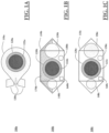
- FIG. 1A presents an elevation drawing showing a first packaging arrangement 100a for the disclosed marine vibrator.
- marine vibrator 100a is comprised of hydrodynamic tow body 110a which houses electro-acoustic underwater sound projector 120a.
- the projector employs compliantly suspended piston 122a which vibrates the water at low frequencies using a transducer that resides inside tow body 110a.
- compliantly suspended pistons see, for example, C. H. Sherman and J. L. Butler, Transducers and Arrays for Underwater Sound, pages 51 and 54 (Springer, 1997 ).
- tow body 110a includes, but are not limited to, power electronics to condition and amplify an electrical analog of the waveform that is used to drive the transducer, control-monitoring electronics which provide local control authority and real-time monitoring of all the components and sub-systems, one or more storage tanks (and associated piping and valve network) containing high-pressure gas such as dry air or dry nitrogen to compensate piston 122a as a result of submergence in water, and one or more batteries to provide a temporary source of electrical power to the control-monitoring system during deployment and retrieval operations when power from a survey vessel which deploys marine vibrator 110a may not available.
- power electronics to condition and amplify an electrical analog of the waveform that is used to drive the transducer
- control-monitoring electronics which provide local control authority and real-time monitoring of all the components and sub-systems
- storage tanks and associated piping and valve network
- high-pressure gas such as dry air or dry nitrogen
- batteries to provide a temporary source of electrical power to the control-monitoring
- Hydrodynamic control surfaces 130a are used to control the submergence depth of tow body 110a which is designed to be positively buoyant. Control surfaces 130a also provide the means to maintain proper roll attitude of tow body 110a so that the force vector from the transducer which drives piston 122a is always perpendicular to the Earth's gravity vector. In this way compliantly suspended piston 122a will not statically deflect inward or outward under the action of gravity.
- FIG. 1B presents an elevation drawing showing a second packaging arrangement 100b for the disclosed marine vibrator.
- marine vibrator 100b is comprised of numerous components that are positioned inside free-flooding, load-bearing frame (or truss) 110b which serves as the tow body.
- the components shown within frame 110b include electro-acoustic underwater sound projector 120b with compliantly suspended piston 122b, power electronics module 130b, control-monitoring electronics module 140b, pressure compensation means including a compressed gas storage tank 150b, and battery 160b. All of these components have substantially the same functionality and performance to those described herein for marine vibrator 100a. The only significant difference is how they are packaged.
- Marine vibrator 100b is designed to be positively buoyant and employs buoyancy module 170b to offset the weight of the other components.
- Buoyancy module 170b is typically comprised of either closed-cell foam, syntactic foam, or an air-filled enclosure.
- Buoyancy module 170b is positioned within frame 110b so that the center-of-buoyancy is above the center-of-gravity in order to impart a passive righting moment to the tow body so that proper roll attitude is maintained. In the event additional roll control is desired, a vertical fin can be added.
- FIG. 1C presents an elevation drawing showing a third packing arrangement 100c, being an exemplary packaging embodiment, for the disclosed marine vibrator. From the perspective of viewing marine vibrator 100c from the outside, it is seen that marine vibrator 100c is identical to marine vibrator 100b with the exception that marine vibrator 100c does not employ a buoyancy module. As such, marine vibrator 100c is negatively buoyant.
- marine vibrator 100c comprises free-flooding, load-bearing frame 110c, electro-acoustic underwater sound projector 120c with compliantly suspended piston 122c, power electronics module 130c, control-monitoring electronics module 140c, compressed gas storage tank 150c, and battery 160c. All of these components have substantially the same functionality and performance to those described herein for marine vibrator 100b. Depth and roll control for marine vibrator 100c is described later in this section.
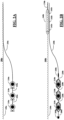
- FIG. 2A presents an elevation drawing showing a first deployment arrangement 200a for the marine vibrator 100a described in FIG. 1A .
- the first deployment arrangement considers a line array (i.e., a sub-array) containing three marine vibrators, for example.
- the number of elements in the array and how many arrays are deployed is dictated by the seismic survey requirements.
- the threeelement array concept presented in FIG. 2A is hypothetical, but fully illustrates a deployment arrangement.
- Deployment arrangement 200a of FIG. 2A shows marine vibrators 210a towed and interconnected by umbilical 220a beneath water surface 230a.
- Umbilical 220a is a flexible, load-bearing structure that is connected to a survey vessel (not shown) up to 1 km away and has functionality to transmit electrical power, transmit and receive data, and transmit compressed gas pursuant to operation of marine vibrators 220a.
- the compressed gas is used to replenish that supplied by the aforementioned storage tank upon initial deployment. Recall that the gas in the storage tank is used to compensate the piston resulting from the hydrostatic loads associated with submergence in water.
- a local source of compressed gas is preferred considering the latency issues of providing the gas directly from the survey vessel located up to 1 km away.
- marine vibrators 200a employ self-contained system hydrodynamic control surfaces 130a (shown in FIG. 1A ) to change/maintain depth and proper roll attitude. This results in very little surface expression and is attractive for marine seismic surveys that are performed in Arctic waters where floating ice is a hazard.
- FIG. 2B presents an elevation drawing showing a second deployment arrangement 200b for the marine vibrator 100b described in FIG. 1B .
- Deployment arrangement 200b of FIG. 2B shows marine vibrators 210b towed and interconnected by umbilical 220b beneath water surface 230b.
- Umbilical 220b has substantially the same functionality of that described earlier for arrangement 200a.
- the submergence depth of marine vibrators 210b is controlled by the confluence of forces resulting from the location of surface float 240b, depressor 250b, and drogue 260b. That is, the weight of umbilical 220b spanning the distance between surface float 240b and depressor 250b is used to submerge marine vibrators 210b.
- the position of surface float 240b determines the submergence depth wherein the position is controlled by cable 270b which is connected to a winch on the survey vessel (not shown).
- Surface float 240b employs guide system (e.g., spring-actuated pinch rollers or equivalent means) 242b to facilitate the positioning process.
- Depressor 250b and drogue 260b provide the requisite downward and horizontal forces on the towed assembly so that marine vibrators 210b are straight and level during seismic survey operations.
- the umbilical interconnects all the components except drogue 250b which is connected to the last element in the array via tether 280b.
- umbilical 220b can optionally terminate at depressor 250b and a mechanical strength member can be used as the means to interconnect marine vibrators 210b with depressor 250b. Electrical power, duplex data, and compressed gas would be facilitated through a network of smaller, flexible umbilicals that are routed from depressor 250b to marine vibrators 210b on a one-to-one correspondence basis. In this way depressor 250b also serves as a forward electronics module.
- Arrangement 200b is well-suited, for example, for deep-water surveys that require marine vibrators to be deployed to depths of nominally 5 m or more.
- FIG. 2C presents an elevation drawing showing a third deployment arrangement 200c, being an embodiment, for the marine vibrator 100c described in FIG. 1C .
- Deployment embodiment 200c of FIG. 2C shows marine vibrators 210c suspended from surface float 220c and towed beneath water surface 230c using umbilical 240c, which is connected to the forward end of surface float 220c.
- Umbilical 240c has substantially the same functionality as that described earlier for arrangement 200a.
- the submergence depth of marine vibrators 210c is controlled by adjusting the length of load-bearing cables 242c using a series of winches (not shown) positioned in surface float 220c.
- Umbilical 240c is broken out into network of smaller, flexible umbilicals 244c in order to facilitate transmission of electrical power, duplex data, and compressed gas to marine vibrators 210c.
- the breakout is accomplished using means (not shown) positioned in surface float 220c.
- Embodiment 200c is inherently stable from a roll attitude standpoint and well-suited, for example, for shallow- or deep-water surveys that require marine vibrators to be deployed to depths of nominally 5 m or less. Of the three deployment arrangements disclosed herein, embodiment 200c is considered the best for marine seismic surveys performed in the transition zone.
- FIG. 2D presents an elevation drawing showing a fourth deployment arrangement 200d for the marine vibrator 100c described in FIG. 1C .
- Deployment arrangement 200d of FIG. 2D shows marine vibrators 210d suspended from surface float 220d and towed beneath water surface 230d using umbilical 240d, which is connected to the forward-most marine vibrator 210d.
- Umbilical 240d has substantially the same functionality as that described earlier for arrangement 200a.
- the submergence depth of marine vibrators 210d is controlled by adjusting the length of load-bearing cables 242d using a series of winches (not shown) positioned in surface float 220d.
- Umbilical 240a also serves as the interconnect tow cable between all marine vibrators 210d in the array and facilitates transmission of electrical power, duplex data, and compressed gas to marine vibrators 210d.
- arrangement 200d is inherently stable from a roll-attitude standpoint and well-suited, for example, for shallow- or deep-water surveys that require marine vibrators to be deployed to depths of nominally 5 m or less. Further, arrangement 200d offers flexibility (relative to embodiment 200c ) in the tow point connection for the umbilical so that it is compatible with the seismic survey requirements and survey vessel capabilities for deployment and recovery.
- position of line arrays as per arrangements 200a, 200b, 200c, and 200d can be determined through a combination of acoustic means (i.e., ultra-short baseline positioning system) and global positioning system transceivers strategically located on the sub-surface and surface components, including the survey vessel, as appropriate.
- acoustic means i.e., ultra-short baseline positioning system
- global positioning system transceivers strategically located on the sub-surface and surface components, including the survey vessel, as appropriate.
- marine vibrator configurations can be implemented at least in part in the form of one or more software programs stored in memory and executed by a processor of a processing device such as a computer.
- a memory or other storage device having such program code embodied therein is an example of what is more generally referred to herein as a "computer program product.”
- the disclosed marine vibrator configurations may be implemented, at least in part, using one or more processing platforms.
- One or more of the processing modules or other components may therefore each run on a computer, storage device or other processing platform element.
- a given such element may be viewed as an example of what is more generally referred to as a "processing device.”
Landscapes
- Life Sciences & Earth Sciences (AREA)
- Physics & Mathematics (AREA)
- Engineering & Computer Science (AREA)
- Remote Sensing (AREA)
- General Life Sciences & Earth Sciences (AREA)
- Environmental & Geological Engineering (AREA)
- Geology (AREA)
- Acoustics & Sound (AREA)
- General Physics & Mathematics (AREA)
- Geophysics (AREA)
- Oceanography (AREA)
- Chemical & Material Sciences (AREA)
- Combustion & Propulsion (AREA)
- Mechanical Engineering (AREA)
- Ocean & Marine Engineering (AREA)
- Geophysics And Detection Of Objects (AREA)
- Transducers For Ultrasonic Waves (AREA)
- Revetment (AREA)
Claims (6)
- Meeresvibratorsystem, das dazu konfiguriert ist, von einem Vermessungsschiff geschleppt zu werden, umfassend:ein Treibkörper (220c), umfassend eine Vielzahl von Winden;ein Versorgungskabel (240c), das mit dem Vermessungsschiff verbunden ist und dazu konfiguriert ist, das Meeresvibratorsystem zu schleppen, wobei das Versorgungskabel weiterhin dazu konfiguriert ist, elektrische Energie zu übertragen und Daten entsprechend einem Betrieb von Meeresvibratoren zu übertragen und zu empfangen;eine Vielzahl von Meeresvibratoren (100c, 210c), wobei jeder von der Vielzahl von Meeresvibratoren umfasst:
einen frei durchfluteten, lasttragenden Rahmen (110c), der von dem Treibkörper hängt, wobei der frei durchflutete, lastragende Rahmen umfasst:einen Niederfrequenz-Elektroakustik-Projektor (120c); ein Leistungselektroniksystem (130c);ein Steuer-Überwachungselektroniksystem (140c) undein Druckausgleichssystem (150c, 160c),wobei jeder von der Vielzahl von Meeresvibratoren einen negativen Auftrieb aufweist, wobei eine Tauchtiefe der Vielzahl von Meeresvibratoren unter Verwendung der Vielzahl von Winden, die in dem Treibkörper positioniert sind, gesteuert wird, wobei die Vielzahl von Winden dazu konfiguriert ist, jeden von der Vielzahl von Meeresvibratoren durch eine oder mehrere jeweilige lasttragende Kabelanordnungen, die mit dem Meeresvibrator verbunden sind, von dem Treibkörper zu hängen, wobei ein Schlepppunkt an einem vorderen Ende des Treibkörpers in Bezug auf eine Richtung in der die Vielzahl von Meeresvibratoren geschleppt werden, angeordnet ist, wobei die Vielzahl der Meeresvibratoren in einem Linienarray eingerichtet ist, und wobei das Versorgungskabel (240c) innerhalb des Treibkörpers in ein Netzwerk von kleineren, flexiblen Versorgungsleitungen (244c) aufgeteilt ist, wobei jede der kleineren flexiblen Versorgungsleitungen mit einem jeweiligen von der Vielzahl von Meeresvibratoren verbunden ist. - Meeresvibratorsystem nach Anspruch 1, wobei das Versorgungskabel weiterhin dazu konfiguriert ist, Druckgas entsprechend einem Betrieb der Meeresvibratoren zu übertragen.
- Meeresvibratorsystem nach Anspruch 1, wobei die Vielzahl von Winden innerhalb eines Innenraums des Treibkörpers positioniert ist.
- Meeresvibratorsystem nach Anspruch 1, umfassend eine Vielzahl von Linienarrays, die positioniert sind, um ein planares oder volumetrisches Array zu bilden, das von dem Vermessungsschiff unter der Wasseroberfläche geschleppt wird.
- Meeresvibratorsystem nach Anspruch 1, wobei der frei durchflutete, lasttragende Rahmen weiterhin eine Quelle einer lokalen elektrischen Energie und eines Hochdruckgases umfasst.
- Meeresvibratorsystem nach Anspruch 1, wobei die Tauchtiefe der Vielzahl von Meeresvibratoren von den Längen der einen oder der mehreren lasttragenden Kabelanordnungen, die jeden Meeresvibrator hängen lassen, abhängt.
Applications Claiming Priority (2)
| Application Number | Priority Date | Filing Date | Title |
|---|---|---|---|
| US201562215463P | 2015-09-08 | 2015-09-08 | |
| PCT/US2016/049627 WO2017044360A1 (en) | 2015-09-08 | 2016-08-31 | Method of packaging and deploying marine vibrator |
Publications (4)
| Publication Number | Publication Date |
|---|---|
| EP3347744A1 EP3347744A1 (de) | 2018-07-18 |
| EP3347744A4 EP3347744A4 (de) | 2019-09-11 |
| EP3347744B1 true EP3347744B1 (de) | 2024-07-17 |
| EP3347744C0 EP3347744C0 (de) | 2024-07-17 |
Family
ID=58240415
Family Applications (1)
| Application Number | Title | Priority Date | Filing Date |
|---|---|---|---|
| EP16844903.1A Active EP3347744B1 (de) | 2015-09-08 | 2016-08-31 | Meeresvibratorsystem und verfahren zum verpacken und einsetzen von meeresvibratoren |
Country Status (9)
| Country | Link |
|---|---|
| US (1) | US11402531B2 (de) |
| EP (1) | EP3347744B1 (de) |
| CN (1) | CN108139496B (de) |
| AU (1) | AU2016318467B2 (de) |
| BR (1) | BR112018004656B1 (de) |
| ES (1) | ES2991793T3 (de) |
| MX (1) | MX390249B (de) |
| RU (1) | RU2718146C2 (de) |
| WO (1) | WO2017044360A1 (de) |
Families Citing this family (4)
| Publication number | Priority date | Publication date | Assignee | Title |
|---|---|---|---|---|
| CN109991590B (zh) * | 2019-02-21 | 2021-02-02 | 中国船舶重工集团公司第七一五研究所 | 一种在有限空间压力罐内测试换能器低频发射特性的系统与方法 |
| CN114018396B (zh) * | 2021-10-22 | 2024-08-06 | 中国舰船研究设计中心 | 一种低频水声测量系统及布设方法 |
| CN120225917A (zh) * | 2022-12-02 | 2025-06-27 | 应用物理技术公司 | 具有一个或更多个远程定位部件的海洋振动器 |
| CN119984472B (zh) * | 2025-04-17 | 2025-08-22 | 浙江大学 | 基于垂向振动隔离混合涡破碎分析的低噪声飘带垂直阵 |
Family Cites Families (14)
| Publication number | Priority date | Publication date | Assignee | Title |
|---|---|---|---|---|
| US2981073A (en) * | 1956-07-27 | 1961-04-25 | American Mach & Foundry | Underwater craft |
| US4198706A (en) * | 1959-08-21 | 1980-04-15 | The United States Of America As Represented By The Secretary Of The Navy | Generation of low frequency sound under water |
| JPH10100990A (ja) | 1996-09-27 | 1998-04-21 | Mitsubishi Heavy Ind Ltd | 海洋浮体構造 |
| GB2332946A (en) * | 1998-01-02 | 1999-07-07 | Michael Swanson | Submarine exploration system and associated marine devices |
| RU13929U1 (ru) * | 2000-02-08 | 2000-06-10 | Государственное предприятие "Научно-исследовательский и проектный институт геофизических методов разведки океана" | Система морской сейсморазведки и концевой буй сейсмокосы |
| AU2007273253B2 (en) * | 2006-07-13 | 2010-07-22 | Exxonmobil Upstream Research Company | Method to maintain towed dipole source orientation |
| FR2913228B1 (fr) * | 2007-03-02 | 2009-05-29 | Saipem S A Sa | Dispositif de decoupe et ouverture/fermeture d'un orifice dans une paroi au fond de la mer |
| US8570829B2 (en) * | 2009-12-22 | 2013-10-29 | Pgs Geophysical As | Depth steerable seismic source array |
| US8446798B2 (en) * | 2010-06-29 | 2013-05-21 | Pgs Geophysical As | Marine acoustic vibrator having enhanced low-frequency amplitude |
| US8817574B2 (en) * | 2011-05-11 | 2014-08-26 | Pgs Geophysical As | Method and system of a compound buoy |
| CN103890614B (zh) * | 2011-08-24 | 2016-10-12 | 斯蒂芬·凯尔明斯基 | 用于水下地震勘探的海洋振动声源 |
| US9535179B2 (en) * | 2011-08-24 | 2017-01-03 | Stephen Chelminski | Marine vibratory sound source for beneath water seismic exploration |
| US9625598B2 (en) * | 2012-08-13 | 2017-04-18 | Applied Physical Sciences Corp. | Coherent sound source for marine seismic surveys |
| US10473803B2 (en) * | 2013-02-08 | 2019-11-12 | Pgs Geophysical As | Marine seismic vibrators and methods of use |
-
2016
- 2016-08-31 WO PCT/US2016/049627 patent/WO2017044360A1/en not_active Ceased
- 2016-08-31 CN CN201680052180.5A patent/CN108139496B/zh not_active Expired - Fee Related
- 2016-08-31 AU AU2016318467A patent/AU2016318467B2/en active Active
- 2016-08-31 US US15/755,807 patent/US11402531B2/en active Active
- 2016-08-31 RU RU2018112262A patent/RU2718146C2/ru active
- 2016-08-31 ES ES16844903T patent/ES2991793T3/es active Active
- 2016-08-31 BR BR112018004656-6A patent/BR112018004656B1/pt active IP Right Grant
- 2016-08-31 MX MX2018002822A patent/MX390249B/es unknown
- 2016-08-31 EP EP16844903.1A patent/EP3347744B1/de active Active
Also Published As
| Publication number | Publication date |
|---|---|
| BR112018004656B1 (pt) | 2023-12-12 |
| ES2991793T3 (es) | 2024-12-04 |
| EP3347744C0 (de) | 2024-07-17 |
| RU2718146C2 (ru) | 2020-03-30 |
| BR112018004656A2 (pt) | 2018-09-25 |
| US11402531B2 (en) | 2022-08-02 |
| EP3347744A4 (de) | 2019-09-11 |
| RU2018112262A3 (de) | 2019-11-27 |
| AU2016318467B2 (en) | 2022-04-07 |
| RU2018112262A (ru) | 2019-10-09 |
| MX2018002822A (es) | 2018-09-07 |
| CN108139496B (zh) | 2020-10-30 |
| HK1251040A1 (zh) | 2019-01-18 |
| US20180329098A1 (en) | 2018-11-15 |
| CN108139496A (zh) | 2018-06-08 |
| WO2017044360A1 (en) | 2017-03-16 |
| AU2016318467A1 (en) | 2018-04-05 |
| MX390249B (es) | 2025-03-20 |
| EP3347744A1 (de) | 2018-07-18 |
| CA2996954A1 (en) | 2017-03-16 |
Similar Documents
| Publication | Publication Date | Title |
|---|---|---|
| US9297920B2 (en) | Enhanced method and device for aquatic seismic prospecting | |
| EP0613025B1 (de) | Gerät und Verfahren zum Positionieren von Schleppsystemen bei der meeresseismischen Vermessung | |
| US9081119B2 (en) | Underseas seismic acquisition | |
| EP3347744B1 (de) | Meeresvibratorsystem und verfahren zum verpacken und einsetzen von meeresvibratoren | |
| CN108367798A (zh) | 动态控制型箔片系统和方法 | |
| US6002648A (en) | Slotted cylinder marine siesmic method and source | |
| CA2508206C (en) | Sonar array system | |
| NO328212B1 (no) | Marin seismisk kilde | |
| US20170350978A1 (en) | Deep water sonar imagining by multibeam echosounder | |
| US10018743B2 (en) | Deep towed seismic source string | |
| EP3344532B1 (de) | Anordnung aus zwei körpern für eine ziehbare vorrichtung in einem sonarsystem | |
| US20140169125A1 (en) | Seismic Data Acquisition System Comprising at Least One Towfish Tail Device Connectable to a Tail of a Towed Acoustic Linear Antenna | |
| CA2996954C (en) | Method of packaging and deploying marine vibrator | |
| HK1251040B (zh) | 封装和部署海洋振动器的方法 | |
| RU2672044C2 (ru) | Морская сейсморазведка с использованием буксируемых компонентов, находящихся ниже поверхности воды | |
| WO2016014926A1 (en) | Marine seismic surveying with towed components below water's surface | |
| US20140269171A1 (en) | Seismic streamer system |
Legal Events
| Date | Code | Title | Description |
|---|---|---|---|
| STAA | Information on the status of an ep patent application or granted ep patent |
Free format text: STATUS: THE INTERNATIONAL PUBLICATION HAS BEEN MADE |
|
| PUAI | Public reference made under article 153(3) epc to a published international application that has entered the european phase |
Free format text: ORIGINAL CODE: 0009012 |
|
| STAA | Information on the status of an ep patent application or granted ep patent |
Free format text: STATUS: REQUEST FOR EXAMINATION WAS MADE |
|
| 17P | Request for examination filed |
Effective date: 20180308 |
|
| AK | Designated contracting states |
Kind code of ref document: A1 Designated state(s): AL AT BE BG CH CY CZ DE DK EE ES FI FR GB GR HR HU IE IS IT LI LT LU LV MC MK MT NL NO PL PT RO RS SE SI SK SM TR |
|
| AX | Request for extension of the european patent |
Extension state: BA ME |
|
| DAV | Request for validation of the european patent (deleted) | ||
| DAX | Request for extension of the european patent (deleted) | ||
| RIC1 | Information provided on ipc code assigned before grant |
Ipc: G01V 1/145 20060101ALI20190408BHEP Ipc: G01V 1/135 20060101ALI20190408BHEP Ipc: G01V 1/143 20060101AFI20190408BHEP Ipc: G01V 1/38 20060101ALI20190408BHEP |
|
| A4 | Supplementary search report drawn up and despatched |
Effective date: 20190808 |
|
| RIC1 | Information provided on ipc code assigned before grant |
Ipc: G01V 1/38 20060101ALI20190802BHEP Ipc: G01V 1/143 20060101AFI20190802BHEP Ipc: G01V 1/135 20060101ALI20190802BHEP Ipc: G01V 1/145 20060101ALI20190802BHEP |
|
| STAA | Information on the status of an ep patent application or granted ep patent |
Free format text: STATUS: EXAMINATION IS IN PROGRESS |
|
| 17Q | First examination report despatched |
Effective date: 20201103 |
|
| GRAP | Despatch of communication of intention to grant a patent |
Free format text: ORIGINAL CODE: EPIDOSNIGR1 |
|
| STAA | Information on the status of an ep patent application or granted ep patent |
Free format text: STATUS: GRANT OF PATENT IS INTENDED |
|
| INTG | Intention to grant announced |
Effective date: 20240206 |
|
| GRAS | Grant fee paid |
Free format text: ORIGINAL CODE: EPIDOSNIGR3 |
|
| GRAA | (expected) grant |
Free format text: ORIGINAL CODE: 0009210 |
|
| STAA | Information on the status of an ep patent application or granted ep patent |
Free format text: STATUS: THE PATENT HAS BEEN GRANTED |
|
| AK | Designated contracting states |
Kind code of ref document: B1 Designated state(s): AL AT BE BG CH CY CZ DE DK EE ES FI FR GB GR HR HU IE IS IT LI LT LU LV MC MK MT NL NO PL PT RO RS SE SI SK SM TR |
|
| REG | Reference to a national code |
Ref country code: GB Ref legal event code: FG4D |
|
| REG | Reference to a national code |
Ref country code: CH Ref legal event code: EP |
|
| REG | Reference to a national code |
Ref country code: DE Ref legal event code: R096 Ref document number: 602016088471 Country of ref document: DE |
|
| REG | Reference to a national code |
Ref country code: IE Ref legal event code: FG4D |
|
| U01 | Request for unitary effect filed |
Effective date: 20240816 |
|
| U07 | Unitary effect registered |
Designated state(s): AT BE BG DE DK EE FI FR IT LT LU LV MT NL PT RO SE SI Effective date: 20240902 |
|
| REG | Reference to a national code |
Ref country code: ES Ref legal event code: FG2A Ref document number: 2991793 Country of ref document: ES Kind code of ref document: T3 Effective date: 20241204 |
|
| U20 | Renewal fee for the european patent with unitary effect paid |
Year of fee payment: 9 Effective date: 20241106 |
|
| PG25 | Lapsed in a contracting state [announced via postgrant information from national office to epo] |
Ref country code: PL Free format text: LAPSE BECAUSE OF FAILURE TO SUBMIT A TRANSLATION OF THE DESCRIPTION OR TO PAY THE FEE WITHIN THE PRESCRIBED TIME-LIMIT Effective date: 20240717 Ref country code: GR Free format text: LAPSE BECAUSE OF FAILURE TO SUBMIT A TRANSLATION OF THE DESCRIPTION OR TO PAY THE FEE WITHIN THE PRESCRIBED TIME-LIMIT Effective date: 20241018 |
|
| PG25 | Lapsed in a contracting state [announced via postgrant information from national office to epo] |
Ref country code: IS Free format text: LAPSE BECAUSE OF FAILURE TO SUBMIT A TRANSLATION OF THE DESCRIPTION OR TO PAY THE FEE WITHIN THE PRESCRIBED TIME-LIMIT Effective date: 20241117 |
|
| PG25 | Lapsed in a contracting state [announced via postgrant information from national office to epo] |
Ref country code: HR Free format text: LAPSE BECAUSE OF FAILURE TO SUBMIT A TRANSLATION OF THE DESCRIPTION OR TO PAY THE FEE WITHIN THE PRESCRIBED TIME-LIMIT Effective date: 20240717 |
|
| PG25 | Lapsed in a contracting state [announced via postgrant information from national office to epo] |
Ref country code: RS Free format text: LAPSE BECAUSE OF FAILURE TO SUBMIT A TRANSLATION OF THE DESCRIPTION OR TO PAY THE FEE WITHIN THE PRESCRIBED TIME-LIMIT Effective date: 20241017 |
|
| PG25 | Lapsed in a contracting state [announced via postgrant information from national office to epo] |
Ref country code: RS Free format text: LAPSE BECAUSE OF FAILURE TO SUBMIT A TRANSLATION OF THE DESCRIPTION OR TO PAY THE FEE WITHIN THE PRESCRIBED TIME-LIMIT Effective date: 20241017 Ref country code: PL Free format text: LAPSE BECAUSE OF FAILURE TO SUBMIT A TRANSLATION OF THE DESCRIPTION OR TO PAY THE FEE WITHIN THE PRESCRIBED TIME-LIMIT Effective date: 20240717 Ref country code: IS Free format text: LAPSE BECAUSE OF FAILURE TO SUBMIT A TRANSLATION OF THE DESCRIPTION OR TO PAY THE FEE WITHIN THE PRESCRIBED TIME-LIMIT Effective date: 20241117 Ref country code: HR Free format text: LAPSE BECAUSE OF FAILURE TO SUBMIT A TRANSLATION OF THE DESCRIPTION OR TO PAY THE FEE WITHIN THE PRESCRIBED TIME-LIMIT Effective date: 20240717 Ref country code: GR Free format text: LAPSE BECAUSE OF FAILURE TO SUBMIT A TRANSLATION OF THE DESCRIPTION OR TO PAY THE FEE WITHIN THE PRESCRIBED TIME-LIMIT Effective date: 20241018 |
|
| REG | Reference to a national code |
Ref country code: CH Ref legal event code: PL |
|
| PG25 | Lapsed in a contracting state [announced via postgrant information from national office to epo] |
Ref country code: SM Free format text: LAPSE BECAUSE OF FAILURE TO SUBMIT A TRANSLATION OF THE DESCRIPTION OR TO PAY THE FEE WITHIN THE PRESCRIBED TIME-LIMIT Effective date: 20240717 |
|
| PG25 | Lapsed in a contracting state [announced via postgrant information from national office to epo] |
Ref country code: MC Free format text: LAPSE BECAUSE OF FAILURE TO SUBMIT A TRANSLATION OF THE DESCRIPTION OR TO PAY THE FEE WITHIN THE PRESCRIBED TIME-LIMIT Effective date: 20240717 Ref country code: CH Free format text: LAPSE BECAUSE OF NON-PAYMENT OF DUE FEES Effective date: 20240831 |
|
| PG25 | Lapsed in a contracting state [announced via postgrant information from national office to epo] |
Ref country code: CZ Free format text: LAPSE BECAUSE OF FAILURE TO SUBMIT A TRANSLATION OF THE DESCRIPTION OR TO PAY THE FEE WITHIN THE PRESCRIBED TIME-LIMIT Effective date: 20240717 |
|
| PG25 | Lapsed in a contracting state [announced via postgrant information from national office to epo] |
Ref country code: SK Free format text: LAPSE BECAUSE OF FAILURE TO SUBMIT A TRANSLATION OF THE DESCRIPTION OR TO PAY THE FEE WITHIN THE PRESCRIBED TIME-LIMIT Effective date: 20240717 |
|
| PLBE | No opposition filed within time limit |
Free format text: ORIGINAL CODE: 0009261 |
|
| STAA | Information on the status of an ep patent application or granted ep patent |
Free format text: STATUS: NO OPPOSITION FILED WITHIN TIME LIMIT |
|
| 26N | No opposition filed |
Effective date: 20250422 |
|
| PG25 | Lapsed in a contracting state [announced via postgrant information from national office to epo] |
Ref country code: IE Free format text: LAPSE BECAUSE OF NON-PAYMENT OF DUE FEES Effective date: 20240831 |
|
| U20 | Renewal fee for the european patent with unitary effect paid |
Year of fee payment: 10 Effective date: 20250814 |
|
| PGFP | Annual fee paid to national office [announced via postgrant information from national office to epo] |
Ref country code: ES Payment date: 20250901 Year of fee payment: 10 |
|
| PGFP | Annual fee paid to national office [announced via postgrant information from national office to epo] |
Ref country code: NO Payment date: 20250715 Year of fee payment: 10 |
|
| PGFP | Annual fee paid to national office [announced via postgrant information from national office to epo] |
Ref country code: GB Payment date: 20250702 Year of fee payment: 10 |
|
| PG25 | Lapsed in a contracting state [announced via postgrant information from national office to epo] |
Ref country code: CY Free format text: LAPSE BECAUSE OF FAILURE TO SUBMIT A TRANSLATION OF THE DESCRIPTION OR TO PAY THE FEE WITHIN THE PRESCRIBED TIME-LIMIT; INVALID AB INITIO Effective date: 20160831 |