EP3347559B1 - Genset for top drive unit - Google Patents
Genset for top drive unit Download PDFInfo
- Publication number
- EP3347559B1 EP3347559B1 EP16766775.7A EP16766775A EP3347559B1 EP 3347559 B1 EP3347559 B1 EP 3347559B1 EP 16766775 A EP16766775 A EP 16766775A EP 3347559 B1 EP3347559 B1 EP 3347559B1
- Authority
- EP
- European Patent Office
- Prior art keywords
- unit
- motor
- casing
- fluid
- swivel
- Prior art date
- Legal status (The legal status is an assumption and is not a legal conclusion. Google has not performed a legal analysis and makes no representation as to the accuracy of the status listed.)
- Active
Links
- 239000012530 fluid Substances 0.000 claims description 145
- 238000004891 communication Methods 0.000 claims description 77
- 238000005553 drilling Methods 0.000 claims description 76
- 230000008878 coupling Effects 0.000 claims description 54
- 238000010168 coupling process Methods 0.000 claims description 54
- 238000005859 coupling reaction Methods 0.000 claims description 54
- 239000004568 cement Substances 0.000 claims description 39
- 230000013011 mating Effects 0.000 claims description 13
- 238000012544 monitoring process Methods 0.000 claims description 9
- 210000000245 forearm Anatomy 0.000 claims description 8
- 230000004044 response Effects 0.000 claims description 4
- 239000002002 slurry Substances 0.000 description 11
- 230000015572 biosynthetic process Effects 0.000 description 10
- 238000005755 formation reaction Methods 0.000 description 10
- 238000005086 pumping Methods 0.000 description 8
- 230000000712 assembly Effects 0.000 description 7
- 238000000429 assembly Methods 0.000 description 7
- 210000002445 nipple Anatomy 0.000 description 7
- 239000000314 lubricant Substances 0.000 description 6
- 239000000463 material Substances 0.000 description 6
- 230000002093 peripheral effect Effects 0.000 description 6
- 239000000523 sample Substances 0.000 description 6
- 230000005611 electricity Effects 0.000 description 5
- 229920000642 polymer Polymers 0.000 description 5
- 230000001012 protector Effects 0.000 description 5
- 230000002829 reductive effect Effects 0.000 description 5
- 229910045601 alloy Inorganic materials 0.000 description 4
- 239000000956 alloy Substances 0.000 description 4
- 238000005520 cutting process Methods 0.000 description 4
- 238000002955 isolation Methods 0.000 description 4
- 229910052751 metal Inorganic materials 0.000 description 4
- 239000002184 metal Substances 0.000 description 4
- 241000239290 Araneae Species 0.000 description 3
- 239000000919 ceramic Substances 0.000 description 3
- 230000006835 compression Effects 0.000 description 3
- 238000007906 compression Methods 0.000 description 3
- 229920001971 elastomer Polymers 0.000 description 3
- 239000000806 elastomer Substances 0.000 description 3
- 229920001198 elastomeric copolymer Polymers 0.000 description 3
- 229930195733 hydrocarbon Natural products 0.000 description 3
- 150000002430 hydrocarbons Chemical group 0.000 description 3
- 239000007788 liquid Substances 0.000 description 3
- 238000000034 method Methods 0.000 description 3
- 239000003921 oil Substances 0.000 description 3
- 230000008569 process Effects 0.000 description 3
- 238000003466 welding Methods 0.000 description 3
- 238000004804 winding Methods 0.000 description 3
- 239000004215 Carbon black (E152) Substances 0.000 description 2
- 230000004913 activation Effects 0.000 description 2
- 230000005540 biological transmission Effects 0.000 description 2
- 239000003990 capacitor Substances 0.000 description 2
- 239000011195 cermet Substances 0.000 description 2
- 230000000295 complement effect Effects 0.000 description 2
- 239000004020 conductor Substances 0.000 description 2
- 239000013078 crystal Substances 0.000 description 2
- 238000010586 diagram Methods 0.000 description 2
- 238000006073 displacement reaction Methods 0.000 description 2
- 238000004146 energy storage Methods 0.000 description 2
- 238000007373 indentation Methods 0.000 description 2
- VNWKTOKETHGBQD-UHFFFAOYSA-N methane Chemical compound C VNWKTOKETHGBQD-UHFFFAOYSA-N 0.000 description 2
- 230000007935 neutral effect Effects 0.000 description 2
- 230000002265 prevention Effects 0.000 description 2
- 230000009467 reduction Effects 0.000 description 2
- 230000000717 retained effect Effects 0.000 description 2
- 230000002441 reversible effect Effects 0.000 description 2
- 238000007789 sealing Methods 0.000 description 2
- 239000007787 solid Substances 0.000 description 2
- 125000006850 spacer group Chemical group 0.000 description 2
- XLYOFNOQVPJJNP-UHFFFAOYSA-N water Substances O XLYOFNOQVPJJNP-UHFFFAOYSA-N 0.000 description 2
- RYGMFSIKBFXOCR-UHFFFAOYSA-N Copper Chemical compound [Cu] RYGMFSIKBFXOCR-UHFFFAOYSA-N 0.000 description 1
- 239000004593 Epoxy Substances 0.000 description 1
- 239000002033 PVDF binder Substances 0.000 description 1
- BQCADISMDOOEFD-UHFFFAOYSA-N Silver Chemical compound [Ag] BQCADISMDOOEFD-UHFFFAOYSA-N 0.000 description 1
- 229910000831 Steel Inorganic materials 0.000 description 1
- 229910001315 Tool steel Inorganic materials 0.000 description 1
- 230000002745 absorbent Effects 0.000 description 1
- 239000002250 absorbent Substances 0.000 description 1
- 229910052782 aluminium Inorganic materials 0.000 description 1
- XAGFODPZIPBFFR-UHFFFAOYSA-N aluminium Chemical compound [Al] XAGFODPZIPBFFR-UHFFFAOYSA-N 0.000 description 1
- 238000004873 anchoring Methods 0.000 description 1
- 239000010426 asphalt Substances 0.000 description 1
- 230000009286 beneficial effect Effects 0.000 description 1
- 239000012267 brine Substances 0.000 description 1
- 239000004927 clay Substances 0.000 description 1
- 239000000356 contaminant Substances 0.000 description 1
- 229910052802 copper Inorganic materials 0.000 description 1
- 239000010949 copper Substances 0.000 description 1
- 239000010779 crude oil Substances 0.000 description 1
- 230000003247 decreasing effect Effects 0.000 description 1
- 239000000839 emulsion Substances 0.000 description 1
- 239000002360 explosive Substances 0.000 description 1
- 239000006260 foam Substances 0.000 description 1
- PCHJSUWPFVWCPO-UHFFFAOYSA-N gold Chemical compound [Au] PCHJSUWPFVWCPO-UHFFFAOYSA-N 0.000 description 1
- 229910052737 gold Inorganic materials 0.000 description 1
- 239000010931 gold Substances 0.000 description 1
- 238000002347 injection Methods 0.000 description 1
- 239000007924 injection Substances 0.000 description 1
- 238000003475 lamination Methods 0.000 description 1
- 239000003077 lignite Substances 0.000 description 1
- 230000000670 limiting effect Effects 0.000 description 1
- 238000004519 manufacturing process Methods 0.000 description 1
- 238000005259 measurement Methods 0.000 description 1
- 239000002086 nanomaterial Substances 0.000 description 1
- 239000003345 natural gas Substances 0.000 description 1
- 230000000149 penetrating effect Effects 0.000 description 1
- 229920002981 polyvinylidene fluoride Polymers 0.000 description 1
- 238000010248 power generation Methods 0.000 description 1
- 230000036316 preload Effects 0.000 description 1
- 238000010926 purge Methods 0.000 description 1
- 230000000452 restraining effect Effects 0.000 description 1
- 239000004576 sand Substances 0.000 description 1
- 230000035939 shock Effects 0.000 description 1
- 229910052709 silver Inorganic materials 0.000 description 1
- 239000004332 silver Substances 0.000 description 1
- HPALAKNZSZLMCH-UHFFFAOYSA-M sodium;chloride;hydrate Chemical compound O.[Na+].[Cl-] HPALAKNZSZLMCH-UHFFFAOYSA-M 0.000 description 1
- 239000010935 stainless steel Substances 0.000 description 1
- 229910001220 stainless steel Inorganic materials 0.000 description 1
- 239000010959 steel Substances 0.000 description 1
- 230000000007 visual effect Effects 0.000 description 1
Images


Classifications
-
- E—FIXED CONSTRUCTIONS
- E21—EARTH DRILLING; MINING
- E21B—EARTH DRILLING, e.g. DEEP DRILLING; OBTAINING OIL, GAS, WATER, SOLUBLE OR MELTABLE MATERIALS OR A SLURRY OF MINERALS FROM WELLS
- E21B19/00—Handling rods, casings, tubes or the like outside the borehole, e.g. in the derrick; Apparatus for feeding the rods or cables
- E21B19/02—Rod or cable suspensions
- E21B19/06—Elevators, i.e. rod- or tube-gripping devices
-
- E—FIXED CONSTRUCTIONS
- E21—EARTH DRILLING; MINING
- E21B—EARTH DRILLING, e.g. DEEP DRILLING; OBTAINING OIL, GAS, WATER, SOLUBLE OR MELTABLE MATERIALS OR A SLURRY OF MINERALS FROM WELLS
- E21B33/00—Sealing or packing boreholes or wells
- E21B33/10—Sealing or packing boreholes or wells in the borehole
- E21B33/13—Methods or devices for cementing, for plugging holes, crevices, or the like
- E21B33/14—Methods or devices for cementing, for plugging holes, crevices, or the like for cementing casings into boreholes
-
- E—FIXED CONSTRUCTIONS
- E21—EARTH DRILLING; MINING
- E21B—EARTH DRILLING, e.g. DEEP DRILLING; OBTAINING OIL, GAS, WATER, SOLUBLE OR MELTABLE MATERIALS OR A SLURRY OF MINERALS FROM WELLS
- E21B19/00—Handling rods, casings, tubes or the like outside the borehole, e.g. in the derrick; Apparatus for feeding the rods or cables
- E21B19/14—Racks, ramps, troughs or bins, for holding the lengths of rod singly or connected; Handling between storage place and borehole
-
- E—FIXED CONSTRUCTIONS
- E21—EARTH DRILLING; MINING
- E21B—EARTH DRILLING, e.g. DEEP DRILLING; OBTAINING OIL, GAS, WATER, SOLUBLE OR MELTABLE MATERIALS OR A SLURRY OF MINERALS FROM WELLS
- E21B19/00—Handling rods, casings, tubes or the like outside the borehole, e.g. in the derrick; Apparatus for feeding the rods or cables
- E21B19/16—Connecting or disconnecting pipe couplings or joints
-
- E—FIXED CONSTRUCTIONS
- E21—EARTH DRILLING; MINING
- E21B—EARTH DRILLING, e.g. DEEP DRILLING; OBTAINING OIL, GAS, WATER, SOLUBLE OR MELTABLE MATERIALS OR A SLURRY OF MINERALS FROM WELLS
- E21B3/00—Rotary drilling
- E21B3/02—Surface drives for rotary drilling
- E21B3/022—Top drives
-
- E—FIXED CONSTRUCTIONS
- E21—EARTH DRILLING; MINING
- E21B—EARTH DRILLING, e.g. DEEP DRILLING; OBTAINING OIL, GAS, WATER, SOLUBLE OR MELTABLE MATERIALS OR A SLURRY OF MINERALS FROM WELLS
- E21B33/00—Sealing or packing boreholes or wells
- E21B33/02—Surface sealing or packing
- E21B33/03—Well heads; Setting-up thereof
- E21B33/04—Casing heads; Suspending casings or tubings in well heads
- E21B33/05—Cementing-heads, e.g. having provision for introducing cementing plugs
-
- E—FIXED CONSTRUCTIONS
- E21—EARTH DRILLING; MINING
- E21B—EARTH DRILLING, e.g. DEEP DRILLING; OBTAINING OIL, GAS, WATER, SOLUBLE OR MELTABLE MATERIALS OR A SLURRY OF MINERALS FROM WELLS
- E21B33/00—Sealing or packing boreholes or wells
- E21B33/02—Surface sealing or packing
- E21B33/03—Well heads; Setting-up thereof
- E21B33/068—Well heads; Setting-up thereof having provision for introducing objects or fluids into, or removing objects from, wells
-
- F—MECHANICAL ENGINEERING; LIGHTING; HEATING; WEAPONS; BLASTING
- F01—MACHINES OR ENGINES IN GENERAL; ENGINE PLANTS IN GENERAL; STEAM ENGINES
- F01C—ROTARY-PISTON OR OSCILLATING-PISTON MACHINES OR ENGINES
- F01C1/00—Rotary-piston machines or engines
- F01C1/08—Rotary-piston machines or engines of intermeshing engagement type, i.e. with engagement of co- operating members similar to that of toothed gearing
- F01C1/10—Rotary-piston machines or engines of intermeshing engagement type, i.e. with engagement of co- operating members similar to that of toothed gearing of internal-axis type with the outer member having more teeth or tooth-equivalents, e.g. rollers, than the inner member
- F01C1/103—Rotary-piston machines or engines of intermeshing engagement type, i.e. with engagement of co- operating members similar to that of toothed gearing of internal-axis type with the outer member having more teeth or tooth-equivalents, e.g. rollers, than the inner member the two members rotating simultaneously around their respective axes
-
- F—MECHANICAL ENGINEERING; LIGHTING; HEATING; WEAPONS; BLASTING
- F01—MACHINES OR ENGINES IN GENERAL; ENGINE PLANTS IN GENERAL; STEAM ENGINES
- F01C—ROTARY-PISTON OR OSCILLATING-PISTON MACHINES OR ENGINES
- F01C13/00—Adaptations of machines or engines for special use; Combinations of engines with devices driven thereby
-
- F—MECHANICAL ENGINEERING; LIGHTING; HEATING; WEAPONS; BLASTING
- F01—MACHINES OR ENGINES IN GENERAL; ENGINE PLANTS IN GENERAL; STEAM ENGINES
- F01C—ROTARY-PISTON OR OSCILLATING-PISTON MACHINES OR ENGINES
- F01C21/00—Component parts, details or accessories not provided for in groups F01C1/00 - F01C20/00
- F01C21/008—Driving elements, brakes, couplings, transmissions specially adapted for rotary or oscillating-piston machines or engines
-
- F—MECHANICAL ENGINEERING; LIGHTING; HEATING; WEAPONS; BLASTING
- F01—MACHINES OR ENGINES IN GENERAL; ENGINE PLANTS IN GENERAL; STEAM ENGINES
- F01C—ROTARY-PISTON OR OSCILLATING-PISTON MACHINES OR ENGINES
- F01C21/00—Component parts, details or accessories not provided for in groups F01C1/00 - F01C20/00
- F01C21/18—Arrangements for admission or discharge of the working fluid, e.g. constructional features of the inlet or outlet
Definitions
- the present disclosure generally relates to a genset for a top drive unit.
- a wellbore is formed to access hydrocarbon-bearing formations (e.g., crude oil and/or natural gas) or for geothermal power generation by the use of drilling. Drilling is accomplished by utilizing a drill bit that is mounted on the end of a drill string. To drill within the wellbore to a predetermined depth, the drill string is often rotated by a top drive on a surface rig. After drilling to a predetermined depth, the drill string and drill bit are removed and a section of casing is lowered into the wellbore. An annulus is thus formed between the string of casing and the formation. The casing string is hung from the wellhead. A cementing operation is then conducted in order to fill the annulus with cement.
- hydrocarbon-bearing formations e.g., crude oil and/or natural gas
- the casing string is cemented into the wellbore by circulating cement into the annulus defined between the outer wall of the casing and the borehole.
- the combination of cement and casing strengthens the wellbore and facilitates the isolation of certain areas of the formation behind the casing for the production of hydrocarbons.
- Top drives are equipped with a motor for rotating the drill string.
- the quill of the top drive is typically threaded for connection to an upper end of the drill pipe in order to transmit torque to the drill string.
- the top drive may also have various accessories to facilitate drilling.
- the drilling accessories are removed from the top drive and a casing running tool is added to the top drive.
- the casing running tool has a threaded adapter for connection to the quill and grippers for engaging an upper end of the casing string. It would be useful to have sensors on the casing running tool to monitor operation thereof. Transmitting electricity from a stationary power source to the rotating casing running tool is problematic. Electrical slip rings are not practical because the top drive operates in a harsh environment where components are exposed to shock and vibration.
- slip rings can spark during operation, they require complex measures, such as flameproof housings or purging with air for use in the explosive atmospheres that sometime occur during casing running operations. Slip rings also utilize brushes requiring frequent replacement. It would be beneficial to provide a local source of electrical power for the various accessories that facilitate drilling.
- US2004/069497 discloses an actuator control system for hydraulic devices; EP1961912 and AU2014215938 describe top drive systems; US2013/269926 discloses a tubular handling apparatus; and US2013/055858 discusses a top drive with slewing power transmission.
- a top drive system includes a motor unit including a control swivel, an accessory tool releasably connected to the motor unit and selected from a group consisting of a casing unit, a cementing unit, and a drilling unit, wherein the accessary tool includes one or more hydraulic passages, and the one or more hydraulic passages are connected to the control swivel when the accessory tool is connected to the motor unit; and a genset mounted to the accessory tool and comprising: a fluid driven motor having an inlet and an outlet for connection to the control swivel via the one or more hydraulic passages in the accessory tool; an electric generator connected to the fluid driven motor; a manifold having an inlet for connection to the control swivel and an outlet connected to an accessory tool actuator; and a control unit in communication with the electric generator and the manifold and comprising a wireless data link.
- the electric generator is configured to power the control unit, and the control unit is configured to operate the manifold in response to instruction signals received by the wireless data
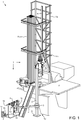
- FIG 1 illustrates a top drive system 1, according to an aspect of the present disclosure.
- the top drive system 1 may be a modular top drive system and may include a linear actuator 1a ( Figure 8A ), several accessory tools (e.g., casing unit 1c, a drilling unit 1d,and a cementing unit 1s) a pipe handler 1p, a unit rack 1k, a motor unit 1m, a rail 1r, and a unit handler 1u.
- the unit handler 1u may include a post 2, a slide hinge 3, an arm 4, a holder 5, a base 6, and one or more actuators (not shown).
- One or more of the accessory tools may include a genset 51 (sometimes referred to as an engine-generator set, and typically including an electric generator and an engine or motor mounted together to form a single piece of equipment).
- genset 51 sometimes referred to as an engine-generator set, and typically including an electric generator and an engine or motor mounted together to form a single piece of equipment.
- the top drive system 1 may be assembled as part of a drilling rig 7 by connecting a lower end of the rail 1r to a floor 7f or derrick 7d of the rig and an upper end of the rail to the derrick 7d such that a front of the rail is adjacent to a drill string opening in the rig floor.
- the rail 1r may have a length sufficient for the top drive system 1 to handle stands 8s of two to four joints of drill pipe 8p.
- the rail length may be greater than or equal to twenty-five meters and less than or equal to one hundred meters.
- the rail 1r may be a monorail (shown) or the top drive system may include twin rails instead of the monorail 1r.
- the base 6 may mount the post 2 on or adjacent to a structure of the drilling rig 7, such as a subfloor structure, such as a catwalk (not shown) or pad.
- the unit rack 1k may also be located on or adjacent to the rig structure.
- the post 2 may extend vertically from the base 6 to a height above the rig floor 7f such that the unit handler 1p may retrieve any of the units 1c,d,s from the rack 1k and deliver the retrieved unit to the motor unit 1m.
- the arm 4 may be connected to the slide hinge 3, such as by fastening.
- the slide hinge 3 may be transversely connected to the post 2, such as by a slide joint, while being free to move longitudinally along the post.
- the slide hinge 3 may also be pivotally connected to a linear actuator (not shown), such as by fastening.
- the slide hinge 3 may longitudinally support the arm 4 from the linear actuator while allowing pivoting of the arm relative to the post 2.
- the unit handler 1u may further include an electric or hydraulic slew motor (not shown) for pivoting the arm 4 about the slide hinge 3.
- the linear actuator may have a lower end pivotally connected to the base 6 and an upper end pivotally connected to the slide hinge 3.
- the linear actuator may include a cylinder and a piston disposed in a bore of the cylinder.
- the piston may divide the cylinder bore into a raising chamber and a lowering chamber and the cylinder may have ports formed through a wall thereof and each port may be in fluid communication with a respective chamber.
- Each port may be in fluid communication with a manifold 60m of a hydraulic power unit (HPU) 60 (both in Figure 5 ) via a control line (not shown).
- Supply of hydraulic fluid to the raising port may move the slide hinge 3 and arm 4 upward to the rig floor 7f.
- Supply of hydraulic fluid to the lowering port may move the slide hinge 3 and arm 4 downward toward the base 6.
- the linear actuator may include an electro-mechanical linear actuator, such as a motor and lead screw or pinion and gear rod, instead of the piston and cylinder assembly.
- an electro-mechanical linear actuator such as a motor and lead screw or pinion and gear rod, instead of the piston and cylinder assembly.
- the arm 4 may include a forearm segment, an aft-arm segment, and an actuated joint, such as an elbow, connecting the arm segments.
- the holder 5 may be releasably connected to the forearm segment, such as by fastening.
- the arm 4 may further include an actuator (not shown) for selectively curling and extending the forearm segment and relative to the aft-arm segment.
- the arm actuator may have an end pivotally connected to the forearm segment and another end pivotally connected to the aft-arm segment.
- the arm actuator may include a cylinder and a piston disposed in a bore of the cylinder.
- the piston may divide the cylinder bore into an extension chamber and a curling chamber and the cylinder may have ports formed through a wall thereof and each port may be in fluid communication with a respective chamber. Each port may be in fluid communication with the HPU manifold 60m via a control line (not shown). Supply of hydraulic fluid to the respective ports may articulate the forearm segment and holder 5 relative to the aft-arm segment toward the respective positions.
- the arm actuator may include an electro-mechanical linear actuator, such as a motor and lead screw or pinion and gear rod, instead of the piston and cylinder assembly.
- the actuated joint may be a telescopic joint instead of an elbow.
- the holder 5 may include a safety latch for retaining any of the units 1c,d,s thereto after engagement of the holder therewith to prevent unintentional release of the units during handling thereof.
- the holder 5 may include a brake for torsionally connecting any of the units 1c,d,s thereto after engagement of the holder therewith to facilitate connection to the motor unit 1m.
- the pipe handler 1p may include a drill pipe elevator 9 ( Figure 9 ), a pair of bails 10, a link tilt 11, and a slide hinge 12.
- the slide hinge 12 may be transversely connected to the front of the rail 1r such as by a slide joint, while being free to move longitudinally along the rail.
- Each bail 10 may have an eyelet formed at each longitudinal end thereof.
- An upper eyelet of each bail 10 may be received by a respective pair of knuckles of the slide hinge 12 and pivotally connected thereto, such as by fastening.
- Each bail 10 may be received by a respective ear of the drill pipe elevator 9d and pivotally connected thereto, such as by fastening.
- the link tilt 11 may include a pair of piston and cylinder assemblies for swinging the elevator 9 relative to the slide hinge 12.
- Each piston and cylinder assembly may have a coupling, such as a hinge knuckle, formed at each longitudinal end thereof.
- An upper hinge knuckle of each piston and cylinder assembly may be received by the respective lifting lug of the slide hinge 12 and pivotally connected thereto, such as by fastening.
- a lower hinge knuckle of each piston and cylinder assembly may be received by a complementary hinge knuckle of the respective bail 10 and pivotally connected thereto, such as by fastening.
- a piston of each piston and cylinder assembly may be disposed in a bore of the respective cylinder.
- the piston may divide the cylinder bore into a raising chamber and a lowering chamber and the cylinder may have ports formed through a wall thereof and each port may be in fluid communication with a respective chamber. Each port may be in fluid communication with the HPU manifold 60m via a respective control line 66b,c ( Figure 5 ). Supply of hydraulic fluid to the raising port may lift the elevator 9 by increasing a tilt angle (measured from a longitudinal axis of the rail 1r). Supply of hydraulic fluid to the lowering port may drop the elevator 9 by decreasing the tilt angle.
- the drill pipe elevator 9 may be manually opened and closed or the pipe handler 1p may include an actuator (not shown) for opening and closing the elevator.
- the drill pipe elevator 9 may include a bushing having a profile, such as a bottleneck, complementary to an upset formed in an outer surface of a joint of the drill pipe 8p adjacent to the threaded coupling thereof.
- the bushing may receive the drill pipe 8p for hoisting one or more joints thereof, such as the stand 8s.
- the bushing may allow rotation of the stand 8s relative to the pipe handler 1p.
- the pipe handler 1p may deliver the stand 8s to a drill string 8 where the stand 8s may be assembled therewith to extend the drill string during a drilling operation.
- the pipe handler 1p When connected to the motor unit 1m, the pipe handler 1p may be capable of supporting the weight of the drill string 8 to expedite tripping of the drill string.
- the linear actuator 1a may raise and lower the pipe handler 1p relative to the motor unit 1m and may include a gear rack, one or two pinions (not shown), and one or two pinion motors (not shown).
- the gear rack may be a bar having a geared upper portion and a plain lower portion.
- the gear rack may have a knuckle formed at a bottom thereof for pivotal connection with a lifting lug of the slide hinge 12, such as by fastening.
- Each pinion may be meshed with the geared upper portion and torsionally connected to a rotor of the respective pinion motor.
- a stator of each pinion motor may be connected to the motor unit 1m and be in electrical communication with a motor driver 61 via a cable 67b (both shown in Figure 5 ).
- the pinion motors may share a cable via a splice (not shown).
- Each pinion motor may be reversible and rotation of the respective pinion in a first direction, such as counterclockwise, may raise the slide hinge 12 relative to the motor unit 1m and rotation of the respective pinion in a second opposite direction, such as clockwise, may lower the slide hinge relative to the motor unit.
- Each pinion motor may include a brake (not shown) for locking position of the slide hinge once the pinion motors are shut off. The brake may be disengaged by supply of electricity to the pinion motors and engaged by shut off of electricity to the pinion motors.
- the linear actuator 1a may be capable of hoisting the stand 8s.
- a stroke of the linear actuator 1a may be sufficient to stab a top coupling of the stand 8s into a quill 37 of the motor unit 1m.
- the unit rack 1k may include a base, a beam, two or more (three shown) columns connecting the base to the beam, such as by welding or fastening, and a parking spot for each of the units 1c,d,s (four spots shown).
- a length of the columns may correspond to a length of the longest one of the units 1c,d,s, such as being slightly greater than the longest length.
- the columns may be spaced apart to form parking spots (four shown) between adjacent columns.
- the units 1c,d,s may be hung from the beam by engagement of the parking spots with respective couplings 15 ( Figure 2B ) of the units.
- Each parking spot may include an opening formed through the beam, a ring gear, and a motor.
- Each ring gear may be supported from and transversely connected to the beam by a bearing (not shown) such that the ring gear may rotate relative to the beam.
- Each bearing may be capable supporting the weight of any of the units 1c,d,s and placement of a particular unit in a particular parking spot may be arbitrary.
- Each motor may include a stator connected to the beam and may be in electrical communication with the motor driver 61 via a cable (not shown).
- a rotor of each motor may be meshed with the respective ring gear for rotation thereof between a disengaged position and an engaged position.
- Each ring gear may have an internal latch profile, such as a bayonet profile
- each coupling 15 may include a head 15h having an external latch profile, such as a bayonet profile.
- the bayonet profiles may each have one or more (three shown) prongs and prong-ways spaced around the respective ring gears and heads 15h at regular intervals.
- the external prongs of the heads 15h may be engaged with the internal prongs of the respective ring gears, thereby supporting the units 1c,d,s from the beam.
- the heads 15h When the external prongs of the heads 15h are aligned with the internal prong-ways of the ring gears (and vice versa), the heads may be free to pass through the respective ring gears.
- the latch profiles may each be threads or load shoulders instead of bayonets.
- the unit rack 1k and the motor unit 1m may each have slips, a cone, and a linear actuator for driving the slips along the cone (or vice versa) instead of the latch profiles.
- Each coupling 15 may further include a neck 15n extending from the head 15h and having a reduced diameter relative to a maximum outer diameter of the head for extending through the respective beam opening and respective ring gear.
- Each coupling 15 may further include a lifting shoulder 15s connected to a lower end of the neck 15n and having an enlarged diameter relative to the reduced diameter of the neck and a torso 15r extending from the lifting shoulder 15s and having a reduced diameter relative to the enlarged diameter of the lifting shoulder.
- the torso 15r may have a length corresponding to a length of the holder 5 for receipt thereof and a bottom of the lifting shoulder 15s may seat on a top of the holder for transport from the unit rack 1k to the motor unit 1m.
- the unit rack 1k may further include a side bar for holding one or more accessories for connection to the forearm segment instead of the holder 5, such as a cargo hook 16 and a pipe clamp 17.
- the side bar may also hold the holder 5 when the unit handler 1u is equipped with one of the accessories.
- FIG 2A illustrates the motor unit 1m.
- the motor unit 1m may include one or more (pair shown) drive motors 18, a becket 19, a hose nipple 20, a mud swivel 21, a drive body 22, a drive ring, such as drive gear 23, a trolley 24 ( Figure 5 ), a thread compensator 25, a control, such as hydraulic, swivel 26, a down thrust bearing 27, an up thrust bearing 28, a backup wrench 29 ( Figure 8A ), a swivel frame 30, a bearing retainer 31, a motor gear 32 ( Figure 5 ), and a latch 69 ( Figure 5 ).
- air shown drive motors 18, a becket 19, a hose nipple 20, a mud swivel 21, a drive body 22, a drive ring, such as drive gear 23, a trolley 24 ( Figure 5 ), a thread compensator 25, a control, such as hydraulic, swivel 26, a down thrust bearing 27, an up thrust bearing 28, a backup
- the drive body 22 may be rectangular, may have thrust chambers formed therein, may have an inner rib dividing the thrust chambers, and may have a central opening formed therethrough and in fluid communication with the chambers.
- the drive gear 23 may be cylindrical, may have a bore therethrough, may have an outer flange 23f formed in an upper end thereof, may have an outer thread formed at a lower end thereof, may have an inner locking profile 23k formed at an upper end thereof, and may have an inner latch profile, such as a bayonet profile 23b, formed adjacently below the locking profile.
- the inner bayonet profile 23b may be similar to the inner bayonet profile of the ring gears except for having a substantially greater thickness for sustaining weight of either the drill string 8 or a casing string 90 ( Figure 12A ).
- the bearing retainer 31 may have an inner thread engaged with the outer thread of the drive gear 23, thereby connecting the two members.
- the drive motors 18 may be electric (shown) or hydraulic (not shown) and have a rotor and a stator.
- a stator of each drive motor 18 may be connected to the trolley 24, such as by fastening, and be in electrical communication with the motor driver 61 via a cable 67c ( Figure 5 ).
- the motors 18 may be operable to rotate the rotor relative to the stator which may also torsionally drive respective motor gears 32.
- the motor gears 32 may be connected to the respective rotors and meshed with the drive gear 23 for torsional driving thereof.
- the motor unit 1m may instead be a direct drive unit having the drive motor 18 centrally located.
- Each thrust bearing 27, 28 may include a shaft washer, a housing washer, a cage, and a plurality of rollers extending through respective openings formed in the cage.
- the shaft washer of the down thrust bearing 27 may be connected to the drive gear 23 adjacent to a bottom of the flange thereof.
- the housing washer of the down thrust bearing 27 may be connected to the drive body 22 adjacent to a top of the rib thereof.
- the cage and rollers of the down thrust bearing 27 may be trapped between the washers thereof, thereby supporting rotation of the drive gear 23 relative to the drive body 22.
- the down thrust bearing 27 may be capable of sustaining weight of a tubular string, such as either the drill string 8 or the casing string 90, during rotation thereof.
- the shaft washer of the up thrust bearing 28 may be connected to the drive gear 23 adjacent to the bearing retainer 31.
- the housing washer of the up thrust bearing 28 may be connected to the drive body 22 adjacent to a bottom of the rib thereof.
- the cage and rollers of the up thrust bearing 28 may be trapped between the washers thereof.
- the trolley 24 may be connected to a back of the drive body 22, such as by fastening.
- the trolley 24 may be transversely connected to a front of the rail 1r and may ride along the rail, thereby torsionally restraining the drive body 22 while allowing vertical movement of the motor unit 1m with a travelling block 73t ( Figure 9 ) of a rig hoist 73.
- the becket 19 may be connected to the drive body 22, such as by fastening, and the becket may receive a hook of the traveling block 73t to suspend the motor unit 1m from the derrick 7d.
- motor unit 1m may include a block-becket instead of the becket 19 and the block-becket may obviate the need for a separate traveling block 73t.
- the hose nipple 20 may be connected to the mud swivel 21 and receive an end of a mud hose (not shown).
- the mud hose may deliver drilling fluid 87 ( Figure 9 ) from a standpipe 79 ( Figure 9 ) to the hose nipple 20.
- the mud swivel 21 may have an outer non-rotating barrel 21o connected to the hose nipple 20 and an inner rotating barrel 21n.
- the mud swivel 21 may have a bearing (not shown) and a dynamic seal (not shown) for accommodating rotation of the rotating barrel relative to the non-rotating barrel.
- the outer non-rotating barrel 21o may be connected to a top of the swivel frame 30, such as by fastening.
- the swivel frame 30 may be connected to a top of the drive body 22, such as by fastening.
- the inner rotating barrel 21n may have an upper portion disposed in the outer non-rotating barrel 21o and a stinger portion extending therefrom, through the control swivel 26, and through the compensator 25.
- a lower end of the stinger portion may carry a stab seal for engagement with an inner seal receptacle 15b of each coupling 15 when the respective unit 1c,d,s is connected to the motor unit 1m, thereby sealing an interface formed between the units.
- the control swivel 26 may include a non-rotating inner barrel and a rotating outer barrel.
- the inner barrel may be connected to the swivel frame 30 and the outer barrel may be supported from the inner barrel by one or more bearings.
- the outer barrel may have hydraulic ports (six shown) formed through a wall thereof, each port in fluid communication with a respective hydraulic passage formed through the inner barrel (only two passages shown). An interface between each port and passage may be straddled by dynamic seals for isolation thereof.
- the inner barrel passages may be in fluid communication with the HPU manifold 60m via a plurality of fluid connectors, such as the hydraulic conduits 64a-e ( Figure 5 ), and the outer barrel ports may be in fluid communication with either the linear actuator 33 or lock ring 34 via jumpers (not shown).
- the outer barrel ports may be disposed along the outer barrel.
- the inner barrel may have a mandrel portion extending along the outer barrel and a head portion extending above the outer barrel. The head portion may connect to the swivel frame 30 and have the hydraulic ports extending therearound.
- the compensator 25 may include a linear actuator 33, the lock ring 34, and one or more (such as three, but only one shown) lock pins 35.
- the lock ring 34 may have an outer flange 34f formed at an upper end thereof, a bore formed therethrough, one or more chambers housing the lock pins 35 formed in an inner surface thereof, a locking profile 34k formed in a lower end thereof, members, such as males 34m, of a hydraulic junction 36 ( Figure 7A ) formed in the lower end thereof, and hydraulic passages (two shown) formed through a wall thereof.
- the locking profile 34k may include a lug for each prong-way of the external bayonet profiles of the heads 15h.
- Each lock pin 35 may be a piston dividing the respective chamber into an extension portion and a retraction portion and the lock ring 34 may have passages formed through the wall thereof for the chamber portions. Each passage may be in fluid communication with the HPU manifold 60m via a respective fluid connector, such as hydraulic conduit 64a ( Figure 3 , only one shown).
- the lock pins 35 may share an extension control line and a retraction control line via a splitter (not shown).
- Supply of hydraulic fluid to the extension passages may move the lock pins 35 to an engaged position where the pins extend into respective slots 15t formed in the prong-ways of the heads 15h, thereby longitudinally connecting the lock ring 34 to a respective unit 1c,d,s.
- Supply of hydraulic fluid to the retraction passages may move the lock pins 35 to a release position (shown) where the pins are contained in the respective chambers of the lock ring 34.
- the linear actuator 33 may include one or more, such as three, piston and cylinder assemblies 33a,b for vertically moving the lock ring 34 relative to the drive gear 23 between a lower hoisting position ( Figure 7A ) and an upper ready position (shown).
- a bottom of the lock ring flange 34f may be seated against a top of the drive gear flange 23f in the hoisting position such that string weight carried by either the drilling unit 1d or the casing unit 1c may be transferred to the drive gear 23 via the flanges and not the linear actuator 33 which may be only capable of supporting stand weight or weight of a casing joint 90j ( Figure 12A ) of casing.
- String weight may be one hundred (or more) times that of stand weight or joint weight.
- a piston of each assembly 33a,b may be seated against the respective cylinder in the ready position.
- Each cylinder of the linear actuator 33 may be disposed in a respective peripheral socket formed through the lock ring flange 34f and be connected to the lock ring 34, such as by threaded couplings.
- Each piston of the linear actuator 33 may extend into a respective indentation formed in a top of the drive gear flange 23f and be connected to the drive gear 23, such as by threaded couplings.
- Each socket of the lock ring flange 34f may be aligned with the respective lug of the locking profile 34k and each indentation of the drive gear flange 23f may be aligned with a receptacle of the locking profile 23k such that connection of the linear actuator 33 to the lock ring 34 and drive gear 23 ensures alignment of the locking profiles.
- Each piston of the linear actuator 33 may be disposed in a bore of the respective cylinder.
- the piston may divide the cylinder bore into a raising chamber and a lowering chamber and the cylinder may have ports (only one shown) formed through a wall thereof and each port may be in fluid communication with a respective chamber.
- Each port may be in fluid communication with the HPU manifold 60m via a respective fluid connector, such as hydraulic conduit 64b (only one shown in Figure 5 ).
- Supply of hydraulic fluid to the raising port may lift the lock ring 34 toward the ready position.
- Supply of hydraulic fluid to the lowering port may drop the lock ring 34 toward the hoisting position.
- a stroke length of the linear compensator 25 between the ready and hoisting positions may correspond to, such as being equal to or slightly greater than, a makeup length of the drill pipe 8p and/or casing joint 90j.
- Each coupling 15 may further include mating members, such as females 15f, of the junction 36 formed in a top of the prongs of the head 15h.
- the male members 34m may each have a nipple for receiving a respective jumper from the control swivel 26, a stinger, and a passage connecting the nipple and the stinger.
- Each stinger may carry a respective seal.
- the female member 15f may have a seal receptacle for receiving the respective stinger.
- the junction members 34m, 15f may be asymmetrically arranged to ensure that the male member 34m is stabbed into the correct female member 15f.
- the backup wrench 29 may include a hinge 29h, a tong 29t, a guide 29g, an arm 29a, a tong actuator (not shown), a tilt actuator (not shown), and a linear actuator (not shown).
- the tong 29t may be transversely connected to the arm 29a while being longitudinally movable relative thereto subject to engagement with a stop shoulder thereof.
- the hinge 29h may pivotally connect the arm 29a to a bottom of the drive body 22.
- the hinge 29h may include a pair of knuckles fastened or welded to the drive body 22 and a pin extending through the knuckles and a hole formed through a top of the arm 29a.
- the tilt actuator may include a piston and cylinder assembly having an upper end pivotally connected to the bottom of the drive body 22 and a lower end pivotally connected to a back of the arm 29a.
- the piston may divide the cylinder bore into an activation chamber and a stowing chamber and the cylinder may have ports (only one shown) formed through a wall thereof and each port may be in fluid communication with a respective chamber. Each port may be in fluid communication with the HPU manifold 60m via a respective control line (not shown).
- Supply of hydraulic fluid to the activation port may pivot the tong 29t about the hinge 29h toward the quill 37.
- Supply of hydraulic fluid to the stowing port may pivot the tong 29t about the hinge 29h away from the quill 37.
- the tong 29t may include a housing having an opening formed therethrough and a pair of jaws (not shown) and the tong actuator may move one of the jaws radially toward or away from the other jaw.
- the guide 29g may be a cone connected to a lower end of the tong housing, such as by fastening, for receiving a threaded coupling, such as a box, of the drill pipe 8p.
- the quill 37 may extend into the tong opening for stabbing into the drill pipe box. Once stabbed, the tong actuator may be operated to engage the movable jaw with the drill pipe box, thereby torsionally connecting the drill pipe box to the drive body 22.
- the tong actuator may be hydraulic and operated by the HPU 60 via a control line 66d ( Figure 5 ).
- the backup wrench linear actuator may include a gear rack (not shown) formed along a straight lower portion of the arm 29a, one or two pinions (not shown), and one or two pinion motors (not shown).
- the arm 29a may have a deviated upper portion engaged with the hinge 29h.
- Each pinion may be meshed with the gear rack of the arm 29a and torsionally connected to a rotor of the respective pinion motor.
- a stator of each pinion motor may be connected to the housing of the tong 29t and be in electrical communication with the motor driver 61 via a cable 67a ( Figure 5 ).
- the pinion motors may share a cable via a splice (not shown).
- Each pinion motor may be reversible and rotation of the respective pinion in a first direction, such as counterclockwise, may raise the tong 29t along the arm 29a and rotation of the respective pinion in a second opposite direction, such as clockwise, may lower the tong along the arm.
- Each pinion motor may include a brake (not shown) for locking position of the tong 29t once the pinion motors are shut off. The brake may be disengaged by supply of electricity to the pinion motors and engaged by shut off of electricity to the pinion motors.
- the latch 69 may include a one or more (pair shown) units disposed at sides of the drive body 22.
- Each latch unit may include a lug connected, such as by fastening or welding, to the drive body 22 and extending from a bottom thereof, a fastener, such as a pin, and an actuator.
- Each lug may have a hole formed therethrough and aligned with a respective actuator.
- Each interior knuckle of the slide hinge 12 may have a hole formed therethrough for receiving the respective latch pin.
- Each actuator may include a cylinder and piston (not shown) connected to the latch pin and disposed in a bore of the cylinder.
- Each cylinder may be connected to the drive body 22, such as by fastening, adjacent to the respective lug.
- the piston may divide the cylinder bore into an extension chamber and a retraction chamber and the cylinder may have ports formed through a wall thereof and each port may be in fluid communication with a respective chamber. Each port may be in fluid communication with the HPU manifold 60m via a control line 66a ( Figure 3 , only one shown).
- the latch units may share an extension control line and a retraction control line via a splitter (not shown). Supply of hydraulic fluid to the extension port may move the pin to an engaged position (shown) where the pin extends through the respective lug hole and the respective interior knuckle hole of the slide hinge 12, thereby connecting the pipe handler 1p to the drive body 22. Supply of hydraulic fluid to the retraction port may move the pin to a release position (not shown) where the pin is clear of the interior slide hinge knuckle.
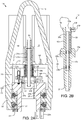
- FIG. 2B illustrates the drilling unit 1d.
- the drilling unit 1d may include the coupling, the quill 37, an internal blowout preventer (IBOP) 38, and one or more, such as two (only one shown), hydraulic passages 39.
- the quill 37 may be a shaft, may have an upper end connected to the torso 15r, may have a bore formed therethrough, may have a threaded coupling, such as a pin, formed at a lower end thereof.
- the IBOP could be controlled from a separate control unit at the accessory tool.
- the separate control unit could be powered from the genset 51.
- the genset 51 could be connected to the tool so as to avoid impacts during the drilling process, such as with springs.
- the IBOP 38 may include an internal sleeve 38v and one or more shutoff valves 38u,b.
- the IBOP may further include an automated actuator for one 38u of the shutoff valves 38u,b and the other 38b of the shutoff valves 38u,b may be manually actuated.
- Each shutoff valve 38u,b may be connected to the sleeve 38v and the sleeve may be received in a recessed portion of the quill 37 and/or coupling 15.
- the IBOP valve actuator may be disposed in a socket formed through a wall of the quill 37 and/or coupling 15 and may include an opening port and/or a closing port and each port may be in fluid communication with the HPU manifold 60m via a respective hydraulic passage 39, respective male 34m and female 15f members, respective jumpers, the control swivel 26, and respective fluid connectors, such as hydraulic conduits 64c,d ( Figure 5 ).
- the hydraulic conduit 64e may connect to a drain port of the IBOP valve actuator.
- FIGS 3A and 3B illustrate the casing unit 1c.
- the casing unit 1c may include the coupling 15, a clamp, such as a spear 40, an adapter 48, one or more, such as three (only one shown), hydraulic passages 49, a fill up tool 50, a genset 51, and a frame 58.
- the fill up tool 50 may include a flow tube 50t, a stab seal, such as a cup seal 50c, a release valve 50r, a mud saver valve 50m, a fill up valve 50f, and a fill up valve actuator 50a.
- the fill up valve 50f may include a valve member, such as a ball, a valve seat, and a housing.
- the housing may be tubular, may have an upper end connected to the torso 15r and a lower end connected to the adapter 48.
- the valve seat may be disposed in the housing, may be made from a metal/alloy, ceramic/cermet, or polymer and may be connected to the housing, such as by fastening.
- the ball may be disposed in a spherical recess formed by the valve seat and rotatable relative to the housing between an open position (shown) and a closed position.
- the ball may have a bore therethrough corresponding to the housing bore and aligned therewith in the open position.
- a wall of the ball may close the housing bore in the closed position.
- the ball may have a stem extending into an actuation port formed through a wall of the housing.
- the stem may mate with a shaft of the actuator 50a and the actuator may be operable to rotate the ball between the open and the closed positions.
- the fill up valve actuator 50a may be hydraulic and may have a position sensor Op in communication with the shaft and in communication with a microcontroller MCU of the genset 51 via a data cable 59a.
- the position sensor Op may also be electrically powered by the microcontroller MCU via the data cable 59a.
- the position sensor Op may verify that the actuator 50a has properly functioned to open and/or close the fill up valve 50f.
- the actuator 50a may be operated by one or more fluid connectors, such as hydraulic conduits 59b,c leading to a fluid, such as hydraulic, manifold 56 ( Figure 4 ) of the genset 51.
- the adapter 48 may be tubular, may have a bore formed therethrough, and may have an upper end connected to the housing of the fill up valve 50f, and may have an outer thread and an inner receptacle formed at a lower end thereof.
- the frame 58 may mount the genset 51 to an outer surface of the adapter 48.
- the spear 40 may include a clamp actuator, such as linear actuator 41, a bumper 42, a collar 43, a mandrel 44, a set of grippers, such as slips 45, a seal joint 46, and a sleeve 47.
- the collar 43 may have an inner thread formed at each longitudinal end thereof.
- the collar upper thread may be engaged with the outer thread of the adapter 48, thereby connecting the two members.
- the collar lower thread may be engaged with an outer thread formed at an upper end of the mandrel 44 and the mandrel may have an outer flange formed adjacent to the upper thread and engaged with a bottom of the collar 43, thereby connecting the two members.
- the seal joint 46 may include the inner barrel, an outer barrel, and a nut.
- the inner barrel may have an outer thread engaged with a threaded portion of the adapter receptacle and an outer portion carrying a seal engaged with a seal bore portion of the adapter receptacle.
- the mandrel 44 may have a bore formed therethrough and an inner receptacle formed at an upper portion thereof and in fluid communication with the bore.
- the mandrel receptacle may have an upper conical portion, a threaded mid portion, and a recessed lower portion.
- the outer barrel may be disposed in the recessed portion of the mandrel 44 and trapped therein by engagement of an outer thread of the nut with the threaded mid portion of the mandrel receptacle.
- the outer barrel may have a seal bore formed therethrough and a lower portion of the inner barrel may be disposed therein and carry a stab seal engaged therewith.
- the linear actuator 41 may include a housing, an upper flange, a plurality of piston and cylinder assemblies, a lower flange, and a position sensor Ret in communication with one or more of the piston and cylinder assemblies.
- the position sensor Ret may be also be in communication with the microcontroller MCU via a data cable 59f.
- the position sensor Ret may also be electrically powered by the microcontroller MCU via the data cable 59f.
- the position sensor Ret may verify that the piston and cylinder assemblies have properly functioned to extend and/or retract the slips 45.
- the housing may be cylindrical, may enclose the cylinders of the assemblies, and may be connected to the upper flange, such as by fastening.
- the collar 43 may also have an outer thread formed at the upper end thereof.
- the upper flange may have an inner thread engaged with the outer collar thread, thereby connecting the two members.
- Each flange may have a pair of lugs for each piston and cylinder assembly connected, such as by fastening or welding, thereto and extending from opposed surfaces thereof.
- Each cylinder of the linear actuator 41 may have a coupling, such as a hinge knuckle, formed at an upper end thereof.
- the upper hinge knuckle of each cylinder may be received by a respective pair of lugs of the upper flange and pivotally connected thereto, such as by fastening.
- Each piston of the linear actuator 41 may have a coupling, such as a hinge knuckle, formed at a lower end thereof.
- Each piston of the linear actuator 41 may be disposed in a bore of the respective cylinder.
- the piston may divide the cylinder bore into a raising chamber and a lowering chamber and the cylinder may have ports formed through a wall thereof and each port may be in fluid communication with a respective chamber.
- Each port may be in fluid communication with the hydraulic manifold 56 via respective fluid connectors, such as hydraulic conduits 59d,e.
- Supply of hydraulic fluid to the raising port may lift the lower flange to a retracted position (shown).
- Supply of hydraulic fluid to the lowering port may drop the lower flange toward an extended position (not shown).
- the piston and cylinder assemblies may share an extension conduit 59e and a retraction conduit 59d via a splitter (not shown).
- the sleeve 47 may have an outer shoulder formed in an upper end thereof trapped between upper and lower retainers.
- a washer may have an inner shoulder formed in a lower end thereof engaged with a bottom of the lower retainer.
- the washer may be connected to the lower flange, such as by fastening, thereby longitudinally connecting the sleeve 47 to the linear actuator 41.
- the sleeve 47 may also have one or more (pair shown) slots formed through a wall thereof at an upper portion thereof.
- the bumper 42 include a striker and a base connected to the mandrel, such as by one or more threaded fasteners, each fastener extending through a hole thereof, through a respective slot of the sleeve 47, and into a respective threaded socket formed in an outer surface of the mandrel 44, thereby also torsionally connecting the sleeve to the mandrel while allowing limited longitudinal movement of the sleeve relative to the mandrel to accommodate operation of the slips 45.
- the striker may be linked to the base by one or more (pair shown) compression springs. A lower portion of the spear 40 may be stabbed into the casing joint 90j until the striker engages a top of the casing joint. The springs may cushion impact with the top of the casing joint 90j to avoid damage thereto.
- the sleeve 47 may extend along the outer surface of the mandrel from the lower flange of the linear actuator 41 to the slips 45.
- a lower end of the sleeve 47 may be connected to upper portions of each of the slips 45, such as by a flanged (i.e., T-flange and T-slot) connection.
- Each slip 46 may be radially movable between an extended position and a retracted position by longitudinal movement of the sleeve 47 relative to the slips.
- a slip receptacle may be formed in an outer surface of the mandrel 44 for receiving the slips 45.
- the slip receptacle may include a pocket for each slip 46, each pocket receiving a lower portion of the respective slip.
- the mandrel 44 may be connected to lower portions of the slips 45 by reception thereof in the pockets.
- Each slip pocket may have one or more (three shown) inclined surfaces formed in the outer surface of the mandrel 44 for extension of the respective slip.
- a lower portion of each slip 46 may have one or more (three shown) inclined inner surfaces corresponding to the inclined slip pocket surfaces.
- each slip 46 may also have a guide profile, such as tabs, extending from sides thereof.
- Each slip pocket may also have a mating guide profile, such as grooves, for retracting the slips 45 when the sleeve 47 moves upward away from the slips.
- Each slip 46 may have teeth formed along an outer surface thereof. The teeth may be made from a hard material, such as tool steel, ceramic, or cermet for engaging and penetrating an inner surface of the casing joint 90j, thereby anchoring the spear 40 to the casing joint.
- the cup seal 50c may have an outer diameter slightly greater than an inner diameter of the casing joint 90j to engage the inner surface thereof during stabbing of the spear 40 therein.
- the cup seal 50c may be directional and oriented such that pressure in the casing bore energizes the seal into engagement with the casing joint inner surface.
- An upper end of the flow tube 50t may be connected to a lower end of the mandrel 44, such as by threaded couplings.
- the mud saver valve 50m may be connected to a lower end of the flow tube 50t, such as by threaded couplings.
- the cup seal 50c and release valve 50r may be disposed along the flow tube 50t and trapped between a bottom of the mandrel 44 and a top of the mudsaver valve 50m.
- the spear 40 may be capable of supporting weight of the casing string 90.
- the string weight may be transferred to the becket 19 via the slips 45, the mandrel 44, the collar 43, the adapter 48, the coupling 15, the bayonet profile 23b, the down thrust bearing 27, the drive body 22.
- Fluid may be injected into the casing string 90 via the hose nipple 20, the mud swivel 21, the coupling 15, the adapter 48, the seal joint 46, the mandrel 44, the flow tube 50t, and the mud saver valve 50m.
- the clamp may be a torque head instead of the spear 40.
- the torque head may be similar to the spear except for receiving an upper portion of the casing joint 90j therein and having the set of grippers for engaging an outer surface of the casing joint instead of the inner surface of the casing joint.
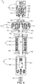
- FIG 4 illustrates the genset 51.
- the genset 51 may include a fluid driven, such as hydraulic, motor 52, a gearbox 53, an electric generator 54, a control unit 55, and the hydraulic manifold 56.
- the gearbox 53 may be a planetary gearbox.
- control swivel 26, the fluid driven motor 52, the fluid manifold 56, the linear actuator 41, and the fill up valve actuator 50a may be pneumatic instead of hydraulic.
- the fluid driven motor 52 may be a gerotor motor and include a housing 52h, a drive shaft 52d, a valve shaft 52v, an output shaft 52o, an orbital gear set having a rotor 52r and a stator 52s, a plurality of roller vanes 52n, and a valve spool 52p.
- the housing 52h may include two or more sections connected together, such as by one or more threaded fasteners.
- the output shaft 52o may have a hollow upper head disposed in the housing and a lower shank extending therethrough. The head may have a torsional profile, such as splines, formed in an inner surface thereof.
- a shaft spacer and a lower portion of the drive shaft 52d may each have teeth meshed with the splines, thereby torsionally connecting the members.
- the shaft spacer may also have a torsional profile formed in an inner surface thereof meshed with a torsional profile formed in a lower end of the valve shaft 52v.
- the drive shaft 52d may be disposed in the head with a sufficient clearance formed therebetween to accommodate articulation of the drive shaft with the orbiting of the rotor 52r.
- the stator 52s may be disposed between the housing sections and connected thereto by the threaded fasteners.
- the roller vanes 52n may be disposed in sockets formed in the stator 52s and may be trapped between the housing sections.
- the rotor 52r may be disposed in the stator 52s and have a number of lobes formed in an outer surface thereof equal to the number of roller vanes minus one.
- Selective supply of pressurized hydraulic fluid by the valve spool 52p through pressure chambers formed between the rotor 52r and the stator 52s may drive the rotor in an orbital movement within the stator, thereby converting fluid energy from the hydraulic fluid into kinetic energy of the output shaft 52o.
- the rotor 52r may have a torsional profile formed in an inner surface thereof meshed with a torsional profile formed of the upper portion of the drive shaft 52d, thereby torsionally connecting the two members.
- the valve shaft 52v may extend through the drive shaft 52s and have an upper portion with a torsional profile meshed with a torsional profile formed in a lower portion of the valve spool 52p.
- An inlet may be formed through a wall of the housing 52h to provide fluid communication between the valve spool 52p and a fluid connector, such as hydraulic conduit 57a leading to the hydraulic passage 49.
- An outlet (not shown) may be formed through a wall of the housing 52h to provide fluid communication between the valve spool 52p and a fluid connector (not shown) leading to a second hydraulic passage of the coupling 15.
- the valve spool 52p may be disposed in the housing 52h and may rotate with the output shaft 52o via the valve shaft 52v.
- the valve spool 52p may have flow slots formed in an outer surface thereof that selectively provide fluid communication between the inlet and outlet and the appropriate pressure chambers formed between the rotor 52r and the stator 52s.
- a bushing may be disposed between the housing 52h and the output shaft 52o for radial support of the output shaft therefrom.
- a thrust bearing may be disposed between the housing 52h and the output shaft 52o for longitudinal support of the output shaft therefrom.
- One or more (pair shown) dynamic seals may be disposed between the housing 52h and the output shaft 52o to isolate the rotating interface therebetween for prevention of loss of hydraulic fluid from the fluid driven motor 52 and for prevention of contaminants from entering therein.
- the gear box 53 may be planetary and include a housing 53h and a cover 53c connected thereto, such as by fasteners (not shown).
- the housing 53h and cover 53c may enclose a lubricant chamber sealed at ends thereof by oil seals.
- the gear box 53 may further include an input disk 53k having a hub extending from an upper end of the lubricant chamber and torsionally connected to the output shaft 52o of the fluid driven motor 52 by mating profiles (not shown), such as splines, formed at adjacent ends thereof.
- the gear box 53 may further include an output shaft 53p extending from a lower end of the lubricant chamber and torsionally connected to a shaft 54s of the electric generator 54 by mating profiles (not shown), such as splines, formed at adjacent ends thereof.
- Each of the output shaft 53p and input disk 53k may be radially supported from the respective cover 53c and housing 53h for rotation relative thereto by respective bearings.
- the hub of the input disk 53k may receive an end of the output shaft 53p and a needle bearing may be disposed therebetween for supporting the output shaft therefrom while allowing relative rotation therebetween.
- a sun gear 53s may be disposed in the lubricant chamber and may be mounted onto the output shaft 53p.
- a stationary housing gear 53g may be disposed in the lubricant chamber and mounted to the housing 53h.
- a plurality of planetary rollers 53r may also be disposed in the lubricant chamber.
- Each planetary roller 53r may include a planetary gear 53e disposed between and meshed with the sun gear 53s and the housing gear 53g.
- the planetary gears 53e may be linked by a carrier 53b which may be radially supported from the output shaft 53p by a bearing to allow relative rotation therebetween.
- Each planetary roller 53r may further include a support shaft 53f which is supported at its free end by a support ring and on which the respective planetary gear 53e may be supported by a bearing.
- Each planetary gear 53e may include first and second sections of different diameters, the first section meshing with the housing gear 53g and the sun gear 53s and the second section meshing with an input gear 53j and a support gear 53b.
- the input gear 53j may be mounted to the input disk 53k by fasteners.
- the support gear 53b may be radially supported from the input shaft 53p by a bearing to allow relative rotation therebetween.
- the support shafts 53f may be arranged at a slight angle with respect to longitudinal axes of the output shaft 53p and input disk 53k.
- the planetary gears 53e, housing gear 53g, input gear 53j, and support gear 53b may also be slightly conical so that, upon assembly of the gear box 53, predetermined traction surface contact forces may be generated.
- the gear box 53 may further include assorted thrust bearings disposed between various members thereof.
- rotation of the input disk 53k by the fluid driven motor 52 may drive the input gear 53j.
- the input gear 53j may drive the planetary gears 53e to roll along the housing gear 53g while also driving the sun gear 53s. Since the diameter of the second section of each planetary gear 53e may be significantly greater than that of the first section, the circumferential speed of the second section may correspondingly be significantly greater than that of the first section, thereby providing for a speed differential which causes the output shaft 53p to counter-rotate at a faster speed corresponding to the difference in diameter between the planetary gear sections. Driving torque of the output shaft 53p is also reduced accordingly.
- the diameter of the first section of each planetary gear 53e may be greater in diameter than that of the second section resulting in rotation of the input gear 53j in the same direction as the input shaft 53p again at a speed corresponding to the difference in diameter between the two sections.
- the electric generator 54 may include a rotor, a stator, and a pair of bearings supporting the rotor for rotation relative to the stator.
- the electric generator 54 may be a permanent magnet generator.
- the rotor may include a hub 54b made from a magnetically permeable material, a plurality of permanent magnets 54m torsionally connected to the hub, and a shaft 54s.
- the rotor may include one or more pairs of permanent magnets 54m having opposite polarities N,S.
- the permanent magnets 54m may also be fastened to the hub 54b, such as by retainers.
- the hub 54b may be torsionally connected to the shaft 54s and fastened thereto.
- the stator may include a housing 54h, a core 54c, a pair of end caps 54p, and a plurality of windings 54w, such as three (only two shown).
- the core 54c may include a stack of laminations made from a magnetically permeable material. The stack may have lobes formed therein, each lobe for receiving a respective winding.
- the core 54c may be longitudinally and torsionally connected to the housing 54h, such as by an interference fit.
- the control unit 55 may include a power converter 55c, an electrical energy storage device, such as a battery 55b, the microcontroller MCU, a wireless data link.
- the wireless data link may include a transmitter TX, a receiver RX, an antenna 55a.
- the transmitter TX and receiver RX may be separate devices (as shown) or may be integrated into a single transceiver.
- the transmitter TX and receiver RX may share the single antenna 55a (shown) or each have their own antenna.
- the wireless data link may be half-duplex or full-duplex.
- the power converter 55c may have an input in electrical communication with each winding 54w of the electric generator 54 and an output in electrical communication with the battery 55b.
- the power converter 55c may receive a multi-phase, such as three phase, power signal from the electric generator 54 and convert the power signal into a direct current power signal for charging the battery 55b.
- the power converter 55c may also step-down a voltage of the power signal from the electric generator 54 to a voltage usable by the battery 55b, such as three, six, nine, twelve, or twenty-four volts.
- the battery 55b may also be in electrical communication with the microcontroller MCU.
- the transmitter TX may be in electrical communication with the microcontroller MCU and the antenna 55a and may include an amplifier, a modulator, and an oscillator.
- the receiver RX may be in electrical communication with the microcontroller MCU and the antenna 55a and may include an amplifier, a demodulator, and a filter.
- the microcontroller MCU may receive instruction signals, via the antenna 55a and receiver RX, from a control console 62 ( Figure 5 ) to operate the fill up valve actuator 50a and/or the linear actuator 41 in response thereto.
- the instruction signals may be radio frequency wireless signals and may also be digital.
- the instruction signals may be received or transmitted with the used of the wireless data link.
- the microcontroller MCU may receive position statuses from the position sensors Op, Ret, and may send the position statuses to the control console 62 via the antenna 55a and transmitter TX.
- the electrical energy storage device may be a super-capacitor, capacitor, or inductor instead of a battery.
- the hydraulic manifold 56 may include a plurality of control valves, such as directional control valves, for operating the fill up valve actuator 50a and the linear actuator 41. Each control valve may be operated by an electric actuator (not shown) in electrical communication with the microcontroller MCU.
- An inlet of the hydraulic manifold 56 may be in fluid communication with the hydraulic passage 49 via a fluid connector, such as hydraulic conduit 57b.
- the inlet of the hydraulic manifold 56 may also be in fluid communication with the second hydraulic passage of the coupling 15 via another fluid connector, such as hydraulic conduit 57c.
- the inlet of the hydraulic manifold 56 may also be in fluid communication with a third hydraulic passage of the coupling 15 via another fluid connector, such as hydraulic conduit 57d.
- the hydraulic conduits 57a,b may both be in simultaneous fluid communication with the hydraulic passage 49 via a splitter.
- the hydraulic conduit 64c may be connected to the hydraulic conduits 57a,b via the control swivel 26 and the hydraulic passage 49.
- the hydraulic conduit 64d may be connected to the hydraulic conduit 57c and the outlet of the fluid driven motor 52 via the control swivel 26 and the second hydraulic passage of the coupling 15.
- the hydraulic conduit 64e may be connected to the hydraulic conduit 57d via the control swivel 26 and the second hydraulic passage of the coupling 15.
- the hydraulic conduit 64c may be a supply line.
- the hydraulic conduit 64d may be a return line.
- the hydraulic conduit 64e may be a drain line.
- the microcontroller MCU may operate the hydraulic manifold 56 to selectively provide fluid communication between the hydraulic conduits 57b-d and the hydraulic conduits 59b-e based on the instruction signals from the control console 62.
- the genset 51 may receive hydraulic fluid from the HPU 60 via the hydraulic conduit 57a, hydraulic passage 49, and hydraulic conduit 64c and return spent hydraulic fluid to the HPU via the hydraulic conduit leading from the second hydraulic passage of the coupling 15, the second hydraulic passage of the coupling, and the hydraulic conduit 64d, thereby driving the fluid driven motor 52.
- the fluid driven motor 52 may in turn drive the electric generator 54 via the gearbox 53.
- the electric generator 54 may power the control unit 55 which may await instruction signals from the control console 62 to operate the spear 40 and/or the fill up valve 50f via the hydraulic manifold 56.
- FIG. 5 is a control diagram of the top drive system 1 in the drilling mode.
- the HPU 60 may include a pump 60p, a check valve 60k, an accumulator 60a, a reservoir 60r of hydraulic fluid, and the HPU manifold 60m.
- the motor driver 61 may be one or more (three shown) phase and include a rectifier 61r and an inverter 61i.
- the inverter 61i may be capable of speed control of the drive motors 18, such as being a pulse width modulator.
- Each of the HPU manifold 60m and motor driver 61 may be in data communication with the control console 62 for control of the various functions of the top drive system 1.
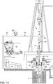
- the top drive system 1 may further include a video monitoring unit 63 having a video camera 63c and a light source 63g such that a technician (not shown) may visually monitor operation thereof from the rig floor 7f or control room (not shown) especially during shifting of the modes.
- the video monitoring unit 63 may be mounted on the motor unit 1m.
- the pipe handler control lines 66b,c may flexible control lines such that the pipe handler 1p remains connected thereto in any position thereof.
- the motor unit 1m may further include a proximity sensor 68 connected to the swivel frame 30 for monitoring a position of the lock ring flange 34f.
- the proximity sensor 68 may include a transmitting coil, a receiving coil, an inverter for powering the transmitting coil, and a detector circuit connected to the receiving coil.
- a magnetic field generated by the transmitting coil may induce eddy current in the turns gear lock ring flange 34f which may be made from an electrically conductive metal or alloy.
- the magnetic field generated by the eddy current may be measured by the detector circuit and supplied to the control console 62 via control line 65.
- Figures 6 , 7A , 7B , 8A, and 8B illustrate shifting of the top drive system 1 to the drilling mode.
- the unit handler 1u may be operated to engage the holder 5 with the torso 15r of the drilling unit 1d. Once engaged, the arm 4 may be raised slightly to shift weight of the drilling unit 1d from the unit rack 1k to the holder 5.
- the respective motor 14m may then be operated to rotate the respective ring gear 14g until the external prongs of the respective head 15h are aligned with the internal prong-ways of the ring gear (and vice versa), thereby freeing the head for passing through the ring gear.
- the arm 4 may then be lowered, thereby passing the drilling unit 1d through the respective ring gear 14g.
- the unit handler 1u may be operated to move the drilling unit 1d away from the unit rack 1k until the drilling unit is clear of the unit rack.
- the arm 4 may be raised to lift the drilling unit 1d above the rig floor 7f.
- the unit handler 1u may be operated to horizontally move the drilling unit 1d into alignment with the motor unit 1m.
- the arm 4 may then be raised to lift the drilling unit 1d until the respective head 15h is adjacent to the bottom of the drive gear 23.
- the drive motors 18 may then be operated to rotate the drive gear 23 until the external prongs of the respective head 15h are aligned with the internal prong-ways of the bayonet profile 23b and at a correct orientation so that when the drive gear is rotated to engage the bayonet profile with the respective head 15h, the asymmetric profiles of the hydraulic junction 36 will be aligned.
- the drive gear 23 may have visible alignment features (not shown) on the bottom thereof to facilitate use of the camera 63c for obtaining the alignment and the orientation.
- the arm 4 may be raised to lift the coupling 15 of the drilling unit 1d into the drive gear 23 until the respective head 15h is aligned with the locking profile 23k thereof.
- the lock ring 34 may be in a lower position, such as the hoisting position, such that the top of the respective head 15h contacts the lock ring and pushes the lock ring upward.
- the proximity sensor 68 may then be used to determine alignment of the respective head 15h with the locking profile 23k by measuring the vertical displacement of the lock ring 34.
- the compensator actuator 33 may be operated to move the lock ring 34 to the ready position.
- the drive motors 18 may then be operated to rotate the drive gear 23 until sides of the external prongs of the respective head 15h engage respective stop lugs of the locking profile 23k, thereby aligning the external prongs of the respective head with the internal prongs of the bayonet profile 23b and correctly orienting the profiles of the hydraulic junction 36.
- the compensator actuator 33 may then be operated to move the lock ring 34 to the hoisting position, thereby moving the lugs of the locking profile 34k into the external prong-ways of the respective head 15h and aligning the lock pins 35 with the respective slots 15t. Movement of the lock ring 34 also stabs the male members 34m into the respective female members 15f, thereby forming the hydraulic junction 36.
- the proximity sensor 68 may again be monitored to ensure that the bayonet profiles 23b have properly engaged and are not jammed. Hydraulic fluid may then be supplied to the extension portions of the chambers housing the lock pins 35 via the control line 64a, thereby moving the lock pins radially inward and into the respective slots 15t.
- the locking profile 23k may have a sufficient length to maintain a torsional connection between the drilling unit 1d and the drive gear 23 in and between the ready and hoisting positions of the compensator 25.
- the drilling unit 1d is now longitudinally and torsionally connected to the drive gear 23.
- the tilt actuator of the backup wrench 29 may then be operated to pivot the arm 29a and tong 29t about the hinge 29h and into alignment with the drilling unit 1d.
- the linear actuator of the backup tong 29 may then be operated via the cable 67a to move the tong 29t upward along the arm 29a until the tong is positioned adjacent to the quill 37.
- the top drive system 1 is now in the drilling mode.
- FIG 9 illustrates the top drive system 1 in the drilling mode.
- the drilling rig 7 may be part of a drilling system.
- the drilling system may further include a fluid handling system 70, a blowout preventer (BOP) 71, a flow cross 72 and the drill string 8.
- BOP blowout preventer
- the drilling rig 7 may further include a hoist 73, a rotary table 74, and a spider 75.
- the rig floor 7f may have the opening through which the drill string 8 extends downwardly through the flow cross 72, BOP 71, and a wellhead 76h, and into a wellbore 77.
- the hoist 73 may include the drawworks 73d, wire rope 73w, a crown block 73c, and the traveling block 73t.
- the traveling block 73t may be supported by wire rope 73w connected at its upper end to the crown block 73c.
- the wire rope 73w may be woven through sheaves of the blocks 73c,t and extend to the drawworks 73d for reeling thereof, thereby raising or lowering the traveling block 73t relative to the derrick 13d.
- the fluid handling system 70 may include a mud pump 78, the standpipe 79, a return line 80, a separator, such as shale shaker 81, a pit 82 or tank, a feed line 83, and a pressure gauge 84.
- a first end of the return line 80 may be connected to the flow cross 72 and a second end of the return line may be connected to an inlet of the shaker 81.
- a lower end of the standpipe 79 may be connected to an outlet of the mud pump 78 and an upper end of the standpipe may be connected to the mud hose.
- a lower end of the feed line 83 may be connected to an outlet of the pit 82 and an upper end of the feed line may be connected to an inlet of the mud pump 78.
- the wellhead 76h may be mounted on a conductor pipe 76c.
- the BOP 71 may be connected to the wellhead 76h and the flow cross 72 may be connected to the BOP, such as by flanged connections.
- the wellbore 77 may be terrestrial (shown) or subsea (not shown). If terrestrial, the wellhead 76h may be located at a surface 85 of the earth and the drilling rig 7 may be disposed on a pad adjacent to the wellhead. If subsea, the wellhead 76h may be located on the seafloor or adjacent to the waterline and the drilling rig 7 may be located on an offshore drilling unit or a platform adjacent to the wellhead.
- the drill string 8 may include a bottomhole assembly (BHA) 8b and a stem.
- the stem may include joints of the drill pipe 8p connected together, such as by threaded couplings.
- the BHA 8b may be connected to the stem, such as by threaded couplings, and include a drill bit and one or more drill collars (not shown) connected thereto, such as by threaded couplings.
- the drill bit may be rotated by the motor unit 1m via the stem and/or the BHA 8b may further include a drilling motor (not shown) for rotating the drill bit.
- the BHA 8b may further include an instrumentation sub (not shown), such as a measurement while drilling (MWD) and/or a logging while drilling (LWD) sub.
- MWD measurement while drilling
- LWD logging while drilling
- the drill string 8 may be used to extend the wellbore 77 through an upper formation 86 and/or lower formation (not shown).
- the upper formation may be non-productive and the lower formation may be a hydrocarbon-bearing reservoir.
- the mud pump 78 may pump the drilling fluid 87 from the pit 82, through the standpipe 79 and mud hose to the motor unit 1m.
- the drilling fluid may include a base liquid.
- the base liquid may be refined or synthetic oil, water, brine, or a water/oil emulsion.
- the drilling fluid 87 may further include solids dissolved or suspended in the base liquid, such as organophilic clay, lignite, and/or asphalt, thereby forming a mud.
- the drilling fluid 87 may flow from the standpipe 79 and into the drill string 8 via the motor 1m and drilling 1d units.
- the drilling fluid 87 may be pumped down through the drill string 8 and exit the drill bit, where the fluid may circulate the cuttings away from the bit and return the cuttings up an annulus formed between an inner surface of the wellbore 77 and an outer surface of the drill string 8.
- the drilling fluid 87 plus cuttings, collectively returns, may flow up the annulus to the wellhead 76h and exit via the return line 80 into the shale shaker 81.
- the shale shaker 81 may process the returns to remove the cuttings and discharge the processed fluid into the mud pit 82, thereby completing a cycle.
- the drill string 8 may be rotated by the motor unit 1m and lowered by the traveling block 73t, thereby extending the wellbore 77.
- Figure 10 illustrates shifting of the top drive system 1 from the drilling mode to the casing mode.
- the drill string 8 may be tripped out from the wellbore 77.
- the drilling unit 1d may be released from the motor unit 1m and loaded onto the unit rack 1k.
- the top drive system 1 may then be shifted into the casing mode by repeating the steps discussed above in relation to Figures 6-8B for the casing unit 1c.
- Figures 11 and 12A illustrate extension of a casing string 90 using the top drive system 1 in the casing mode.
- the holder 5 may be disconnected from the arm 4 and stowed on the side bar 13r.
- the pipe clamp 17 may then be connected to the arm 4 and the unit handler 1u operated to engage the pipe clamp with the casing joint 90j.
- the pipe clamp 17 may be manually actuated between an engaged and disengaged position or include an actuator, such as a hydraulic actuator, for actuation between the positions.
- the casing joint 90j may initially be located on the subfloor structure and the unit handler 1u may be operated to raise the casing joint to the rig floor 7f and into alignment with the casing unit 1c and the unit handler 1h may hold the casing joint while the spear 40 and fill up tool 50 are stabbed into the casing joint.
- the compensator 25 may be stroked upward and the pressure regulator of the HPU manifold 60m may be operated to maintain the compensator actuator 33 at a sensing pressure, such as slightly less than the pressure required to support weight of the lock ring 34 and casing unit 1c, such that the compensator 25 drifts to the hoisting position.
- the bumper 42 may engage a top of the casing joint 90j and the proximity sensor 68 may be monitored by the control console 62 to detect stroking of the compensator 25 to the ready position.
- the camera 63c may also observe stabbing of the spear 40 into the casing joint 90j. Once stabbed, the spear slips 45 may be engaged with the casing joint 90j by operating the linear actuator 41.
- the compensator 25 may be stroked upward and the pressure regulator of the HPU manifold 60m may be operated to maintain the compensator actuator 33 at a second sensing pressure, such as slightly less than the pressure required to support weight of the lock ring 34, casing unit 1c, and casing joint 90j, such that the compensator 25 drifts to the hoisting position.
- the motor 1m and casing 1c units, pipe handler 1p, and casing joint 90j may be lowered by operation of the hoist 73 and a bottom coupling of the casing joint stabbed into the top coupling of the casing string 90.
- the proximity sensor 68 may be monitored by the control console 62 to detect stroking of the compensator 25 to the ready position and the hoist 73 may be locked at the ready position.
- the rotary table 74 may be locked or a backup tong (not shown) may be engaged with the top coupling of the casing string 90 and the drive motors 18 may be operated to spin and tighten the threaded connection between the casing joint 90j and the casing string 90.
- the hydraulic pressure may be maintained in the linear actuator 33 corresponding to the weight of the lock ring 34, casing unit 1c, and casing joint 90j so that the threaded connection is maintained in a neutral condition during makeup.
- the pressure regulator of the HPU manifold 60m may relieve fluid pressure from the linear actuator 33 as the casing joint 90j is being madeup to the casing string 90 to maintain the neutral condition while the compensator 25 strokes downward to accommodate the longitudinal displacement of the threaded connection.
- Figure 12B illustrates running of the extended casing string 90, 90j into the wellbore 77 using the top drive system 1.
- the HPU manifold 60m may be operated to pressurize the linear actuator 33 to exert the downward preload onto the lock ring 34.
- the spider 75 may then be removed from the rotary table 74 to release the extended casing string 90, 90j and running thereof may continue. Injection of the drilling fluid 87 into the extended casing string 90, 90j and rotation thereof by the drive motors 18 allows the casing string to be reamed into the wellbore 77.
- the casing string 90 may be drilled into the formation 86, thereby simultaneously extending the wellbore 77 and deploying the casing string into the wellbore.
- FIGS 13A and 13B illustrate the cementing unit 1s of the top drive system 1.
- the cementing unit 1s may include the coupling 15, the fill up valve 50f and actuator 50a (repurposed as a top drive isolation valve), an adapter 99, the genset 51, the frame 58, the hydraulic passages 49, and a cementing head 88.
- the cementing head 88 may include a cementing swivel 88v, a launcher 88h, a release plug, such as a dart 89, and a dart detector.
- the adapter 99 may similar to the adapter 48 except for having a lower connector, such as a threaded coupling, suitable for mating with the cementing head 88.
- the cementing swivel 88v may include a housing torsionally connected to the drive body 22 or derrick 7d, such as by an arrestor (not shown).
- the cementing swivel 88v may further include a mandrel and bearings for supporting the housing from the mandrel while accommodating rotation of the mandrel.
- An upper end of the mandrel may be connected to a lower end of the adapter 99, such as by threaded couplings.
- the cementing swivel 88v may further include an inlet formed through a wall of the housing and in fluid communication with a port formed through the mandrel and a seal assembly for isolating the fluid communication between the inlet and the port.
- the mandrel port may provide fluid communication between a bore of the cementing head 88 and the housing inlet.
- the launcher 88h may include a body, a deflector, a canister, a gate, the actuator, and a crossover.
- the body may be tubular and may have a bore therethrough.
- An upper end of the body may be connected to a lower end of the cementing swivel 88v, such as by threaded couplings, and a lower end of the body may be connected to the crossover, such as by threaded couplings.
- the canister and deflector may each be disposed in the body bore.
- the deflector may be connected to the cementing swivel mandrel, such as by threaded couplings.
- the canister may be longitudinally movable relative to the body.
- the canister may be tubular and have ribs formed along and around an outer surface thereof. Bypass passages (only one shown) may be formed between the ribs.
- the canister may further have a landing shoulder formed in a lower end thereof for receipt by a landing shoulder of the adapter.
- the deflector may be operable to divert fluid received from a cement line 92 ( Figure 14 ) away from a bore of the canister and toward the bypass passages.
- the crossover may have a threaded coupling, such as a threaded pin, formed at a lower end thereof for connection to a work string 91 ( Figure 14 ).
- the dart 89 may be disposed in the canister bore.
- the dart 89 may be made from one or more drillable materials and include a finned seal and mandrel.
- the mandrel may be made from a metal or alloy and may have a landing shoulder and carry a landing seal for engagement with the seat and seal bore of a wiper plug (not shown) of the work string 91.
- the gate of the launcher 88h may include a housing, a plunger, and a shaft.
- the housing may be connected to a respective lug formed in an outer surface of the launcher body, such as by threaded couplings.
- the plunger may be radially movable relative to the body between a capture position and a release position.
- the plunger may be moved between the positions by a linkage, such as a jackscrew, with the shaft.
- the shaft may be connected to and rotatable relative to the housing.
- the actuator may be fluid driven, such as a hydraulic, motor, operable to rotate the shaft relative to the housing.
- the actuator may include an inlet and an outlet in fluid communication with the hydraulic manifold 56 via respective conduits 100a,b.
- the console 62 may be operated to supply hydraulic fluid to the launcher actuator via a control line 56 extending to the control swivel 26 and a control line extending from the control swivel to the HPU manifold 60m.
- the launcher actuator may then move the plunger to the release position.
- the canister and dart 89 may then move downward relative to the launcher body until the landing shoulders engage. Engagement of the landing shoulders may close the canister bypass passages, thereby forcing chaser fluid 98 ( Figure 14 ) to flow into the canister bore.
- the chaser fluid 98 may then propel the dart 89 from the canister bore, down a bore of the crossover, and onward through the work string 91.
- control swivel 26 and launcher actuator may be pneumatic or electric.
- the launcher actuator may be linear, such as a piston and cylinder.
- the launcher 88h may include a main body having a main bore and a parallel side bore, with both bores being machined integral to the main body.
- the dart 89 may be loaded into the main bore, and a dart releaser valve may be provided below the dart to maintain it in the capture position.
- the dart releaser valve may be side-mounted externally and extend through the main body. A port in the dart releaser valve may provide fluid communication between the main bore and the side bore. In a bypass position, the dart 89 may be maintained in the main bore with the dart releaser valve closed.
- Fluid may flow through the side bore and into the main bore below the dart via the fluid communication port in the dart releaser valve.
- the dart releaser valve may be turned, such as by ninety degrees, thereby closing the side bore and opening the main bore through the dart releaser valve.
- the chaser fluid 98 may then enter the main bore behind the dart 89, thereby propelling the dart into the work string 91.
- the dart detector may include one or more ultrasonic transducers, such as an active transducer 88a and a passive transducer 88p.
- Each transducer 88a,p may include a respective: bell, a knob, a cap, a retainer, a biasing member, such as compression spring, a linkage, such as a spring housing, and a probe.
- Each bell may have a respective flange formed in an inner end thereof for longitudinal and torsional connection to an outer surface of the crossover, such as by one or more respective fasteners.
- the transducers 88a,p may be arranged on the crossover in alignment and in opposing fashion, such as being spaced around the crossover by one hundred eighty degrees.
- Each bell may have a cavity formed in an inner portion thereof for receiving the respective probe and a smaller bore formed in an outer portion thereof for receiving the respective knob.
- Each knob may be linked to the respective bell, such as by mating lead screws formed in opposing surfaces thereof.
- Each knob may be tubular and may receive the respective spring housing in a bore thereof.
- Each knob may have a first thread formed in an inner surface thereof adjacent to an outer end thereof for receiving the respective cap.
- Each knob may also have a second thread formed in an inner surface thereof adjacent to the respective first thread for receiving the respective retainer.
- Each spring housing may be tubular and have a bore for receiving the respective spring and a closed inner end for trapping an inner end of the spring therein. An outer end of each spring may bear against the respective retainer, thereby biasing the respective probe into engagement with the outer surface of the crossover. A compression force exerted by the spring against the respective probe may be adjusted by rotation of the knob relative to the respective bell.
- Each knob may also have a stop shoulder formed in an inner surface and at a midportion thereof for engagement with a stop shoulder formed in an outer surface of the respective spring housing.
- Each probe may include a respective: shell, jacket, backing, vibratory element, and protector.
- Each shell may be tubular and have a substantially closed outer end for receiving a coupling of the respective spring housing and a bore for receiving the respective backing, vibratory element, and protector.
- Each bell may carry one or more seals in an inner surface thereof for sealing an interface formed between the bell and the respective shell.
- Each seal may be made from an elastomer or elastomeric copolymer and may additionally serve to acoustically isolate the respective probe from the respective bell.
- Each bell and each shell may be made from a metal or alloy, such as steel or stainless steel.
- Each backing may be made from an acoustically absorbent material, such as an elastomer, elastomeric copolymer, or acoustic foam.
- the elastomer or elastomeric copolymer may be solid or have voids formed throughout.
- Each vibratory element may be a disk made from a piezoelectric material, such as natural crystal, synthetic crystal, electroceramic, such as perovskite ceramic, a polymer, such as polyvinylidene fluoride, or organic nanostructure.
- a peripheral electrode may be deposited on an inner face and side of each vibratory element and may overlap a portion of an outer face thereof.
- a central electrode may be deposited on the outer face of each vibratory element.
- a gap may be formed between the respective electrodes and each backing may extend into the respective gap for electrical isolation thereof.
- Each electrode may be made from an electrically conductive material, such as gold, silver, copper, or aluminum. Leads, such as wires, may be connected to the respective electrodes and combine into a cable for extension to an electrical coupling connected to the bell.
- Each pair of wires or each cable may extend through respective conduits formed through the backing and the shell.
- Each backing may be bonded or molded to the respective vibratory element and electrodes.
- Electric cables 100c,d may connect the electrical couplings of the respective transducers 88a,p to the microcontroller MCU.
- the protector may be bonded or molded to the respective peripheral electrode.
- Each jacket may be made from an injectable polymer and may bond the respective backing, peripheral electrode, and protector to the respective shell while electrically isolating the peripheral electrode therefrom.
- Each protector may be made from a polymer, such as an engineering polymer or epoxy, and also serve to electrically isolate the respective peripheral electrode from the crossover.
- Figure 14 illustrates cementing of the casing string 90 using the top drive system 1 in a cementing mode.
- a shoe (not shown) of the casing string 90 nears a desired deployment depth of the casing string, such as adjacent a bottom of the lower formation, a casing hanger 90h may be assembled with the casing string 90. Once the casing hanger 90h reaches the rig floor 7f, the spider 75 may be set.
- the casing unit 1c may be released from the motor unit 1m and replaced by the cementing unit 1s using the unit handler 4u.
- the work string 91 may be connected to the casing hanger 90h and the work string extended until the casing hanger 90h seats in the wellhead 76h.
- the work string 91 may include a casing deployment assembly (CDA) 91 d and a stem 91s, such as such as one or more joints of drill pipe connected together, such as by threaded couplings.
- An upper end of the CDA 91d may be connected a lower end of the stem 91s, such as by threaded couplings.
- the CDA 91d may be connected to the casing hanger 90h, such as by engagement of a bayonet lug (not shown) with a mating bayonet profile (not shown) formed the casing hanger.
- the CDA 91d may include a running tool, a plug release system (not shown), and a packoff.
- the plug release system may include an equalization valve and a wiper plug.
- the wiper plug may be releasably connected to the equalization valve, such as by a shearable fastener.
- an upper end of the cement line 92 may be connected to an inlet of the cementing swivel 88v.
- a lower end of the cement line 92 may be connected to an outlet of a cement pump 93.
- a cement shutoff valve 92v and a cement pressure gauge 92g may be assembled as part of the cement line 92.
- An upper end of a cement feed line 94 may be connected to an outlet of a cement mixer 95 and a lower end of the cement feed line may be connected to an inlet of the cement pump 93.
- the fill up valve 50f may be closed and the drive motors 18 may be operated to rotate the work string 91 and casing string 90 during the cementing operation.
- the cement pump 93 may then be operated to inject conditioner 96 from the mixer 95 and down the casing string 90 via the feed line 94, the cement line 92, the cementing head 88, and a bore of the work string 91.
- cement slurry 97 may be pumped from the mixer 95 into the cementing swivel 88v by the cement pump 93.
- the cement slurry 97 may flow into the launcher 88h and be diverted past the dart 89 (not shown) via the diverter and bypass passages.
- the technician may operate the control console 62 to send a command signal to the microcontroller MCU during pumping of cement slurry 97.
- the command signal may instruct the dart detector to switch to an initialization mode for establishing a baseline.
- the microcontroller MCU may transmit input voltage pulses at an ultrasonic frequency to the active transducer 88a and record the amplitude and time of the transmission for each input voltage pulse.
- the active transducer 88a may then convert the voltage pulses into ultrasonic pulses.
- the ultrasonic pulses may travel through the adjacent crossover wall, through fluid contained in/flowing therethrough, and through the distal crossover wall to the passive transducer 88p.
- the passive transducer 88p may convert the received ultrasonic pulses into raw voltage pulses and supply the raw voltage pulses to the microcontroller MCU.
- the microcontroller MCU may refine the raw voltage pulses into output voltage pulses and calculate an amplitude ratio of each output pulse to the respective input pulse and calculate the transit time of each output pulse.
- the microcontroller MCU may then supply the calculated data to the transmitter TX for sending to the control console 62 via the antenna 55a.
- a programmable logic controller (PLC) of the control console 62 may process the data to determine the baseline.
- PLC programmable logic controller
- the dart 89 may be released from the launcher 88h by operating the launcher actuator.
- the chaser fluid 98 may be pumped into the cementing swivel 88v by the cement pump 93.
- the chaser fluid 98 may flow into the launcher 88h and be forced behind the dart 89 by closing of the bypass passages, thereby launching the dart.
- Passing of the dart 89 through the dart detector may substantially decrease amplitudes of the baseline voltage pulses to reduced amplitude voltage pulses.
- the amplitude reduction may be caused by a substantial difference in acoustic impedance between the dart mandrel and the cement slurry 97 reflecting a portion of the pulses back toward the active transducer 88a.
- Passing of the dart 89 through the dart detector may substantially decrease the baseline transit times to faster transit times.
- the transit time reduction may be caused by increased acoustic velocity of the dart mandrel relative to the cement slurry 97.
- the control console 62 may detect passage of the dart 89 using either or both criteria and indicate successful launch of the dart by a visual indicator, such as a light or display screen.
- Pumping of the chaser fluid 98 by the cement pump 93 may continue until residual cement in the cement line 92 has been purged. Pumping of the chaser fluid 98 may then be transferred to the mud pump 78 by closing the valve 92v and opening the fill up valve 50f.
- the dart 89 and cement slurry 97 may be driven through the work string bore by the chaser fluid 98.
- the dart 89 may land onto the wiper plug and continued pumping of the chaser fluid 98 may increase pressure in the work string bore against the seated dart 89 until a release pressure is achieved, thereby fracturing the shearable fastener.
- the cement slurry 97 may flow through a float collar (not shown) and the shoe of the casing string 90, and upward into the annulus.
- Pumping of the chaser fluid 98 may continue to drive the cement slurry 97 into the annulus until the wiper plug bumps the float collar. Pumping of the chaser fluid 98 may then be halted and rotation of the casing string 90 may also be halted. The float collar may close in response to halting of the pumping. The work string 91 may then be lowered to set a packer of the casing hanger 90h. The bayonet connection may be released and the work string 91 may be retrieved to the rig 1r.
- the drilling unit 1d may be used again after the casing or liner string is assembled for assembling the work string used to deploy the assembled casing or liner string into the wellbore 77.
- the top drive system 1 may be shifted back to the drilling mode for assembly of the work string.
- the work string may include a casing or liner deployment assembly and a string of drill pipe such that the drilling unit 1d may be employed to assemble the pipe string.
- the motor unit 1m may be operated for reaming the casing or liner string into the wellbore 77.
- FIG 15 illustrates cementing of the casing string 90 using an alternative cementing unit 101.
- the alternative cementing unit 101 may include the coupling 15, the fill up valve 50f and actuator 50a (repurposed as an IBOP), the adapter 99, the genset 51, the frame 58, the hydraulic passages 49, and a modified cementing head.
- the modified cementing head may include the launcher 88h, a release plug, such as the dart 89, and the dart detector.
- the alternative cementing unit 101 may be similar to the cementing unit 1s except for omission of the cementing swivel 88v.
- a flow tee and shutoff valve 102 may be assembled as part of the standpipe 79 and the upper end of the cement line 92 may be connected to the flow tee.
- the shutoff valve 102 may be closed and the conditioner 96 and cement slurry 97 may be pumped by the cement pump 93 and through the cement line 92, mud hose, motor unit 1m, alternative cementing unit 101, work string 91, and casing string 90.
- the shutoff valve 92v may be closed and the shutoff valve 102 opened and the cementing operation may proceed as discussed above.
- cementing unit 1s, 101 may have a position sensor instead of or in addition to the dart detector and for verifying that the launcher actuator has properly moved the plunger to the release position.
- the casing unit 1c and/or either cementing unit 1s, 101 may have its own control swivel and the hydraulic junction 36 may be omitted.
- the motor unit 1m may have a wireless data link for relaying communication between the control console 62 and the control unit 55.
- the fluid driven motor 52, gearbox 53, electric generator 54, and power converter 55c may be omitted and the battery 55b may have sufficient energy capacity to operate the casing unit 1c and/or either cementing unit 1s, 101 during the respective operations.
- the genset 51 may further include an air compressor driven by the fluid driven motor 52 or the genset may include an electric motor for driving the air compressor.
- the genset 51 may be used with any other accessory tool, such as a drilling unit, a completion tool, a wireline tool, a fracturing tool, a pump, or a sand screen.
- accessory tool such as a drilling unit, a completion tool, a wireline tool, a fracturing tool, a pump, or a sand screen.
- a system includes an accessory tool selected from a group consisting of a casing unit, a cementing unit, and a drilling unit; and a genset mounted to the accessory tool and comprising: a fluid driven motor having an inlet and an outlet for connection to a control swivel of the system; an electric generator connected to the fluid driven motor; a manifold having an inlet for connection to the control swivel and an outlet connected an accessory tool actuator; and a control unit in communication with the electric generator and the manifold and comprising a wireless data link.
- the fluid driven motor is hydraulic.
- the system also includes a fill up valve for opening and closing a bore of the accessory tool; and a fill up valve actuator for operating the fill up valve and connected to the outlet of the manifold.
- the fill up valve actuator comprises a position sensor in communication with the control unit for monitoring operation of the fill up valve actuator.
- the genset further comprises a gearbox connecting the fluid driven motor to the electric generator.
- the fluid driven motor is a gerotor
- the gearbox is a planetary gearbox
- the electric generator is a permanent magnet generator.
- the wireless data link comprises an antenna.
- control unit further comprises at least one of: a power converter in electrical communication with the electric generator; a battery in electrical communication with the power converter; a microcontroller in electrical communication with the battery; a transmitter in electrical communication with the microcontroller and the antenna; and a receiver in electrical communication with the microcontroller and the antenna.
- control swivel is located on a motor unit of the system, the system further comprising: a rail for connection to a drilling rig; and the motor unit, comprising: a drive body; a drive motor having a stator connected to the drive body; a trolley for connecting the drive body to the rail; a drive ring torsionally connected to a rotor of the drive motor; and a swivel frame connected to the drive body and the control swivel.
- the motor unit further comprises: a becket for connection to a hoist of the drilling rig; a mud swivel connected to the swivel frame; and a down thrust bearing for supporting the drive ring for rotation relative to the drive body.
- the system also includes a unit handler locatable on or adjacent to a structure of the drilling rig and operable to retrieve the accessory tool from a rack and deliver the accessory tool to the motor unit.
- the unit handler comprises: an arm; and a holder releasably connected to the arm and operable to carry the accessory tool.
- the unit handler further comprises a pipe clamp releasably connected to the arm and operable to carry a casing joint or liner for delivery to the accessory tool.
- the unit handler further comprises: a base for mounting the unit handler to a subfloor structure of the drilling rig; a post extending from the base to a height above a floor of the drilling rig; a slide hinge transversely connected to the post; and the arm connected to the slide hinge and comprising a forearm segment, an aft-arm segment, and an actuated joint connecting the arm segments.
- the accessory tool is the casing unit;
- the casing unit comprises a clamp comprising: a set of grippers for engaging a surface of a casing joint; and a clamp actuator for selectively engaging and disengaging the set of grippers with the casing joint;
- the genset is mounted to the clamp; and
- the accessory tool actuator is the clamp actuator.
- the casing unit further comprises a stab seal connected to the clamp for engaging an inner surface of the casing joint.
- the clamp comprises a position sensor in communication with the control unit for monitoring operation of the clamp actuator.
- control swivel is located on a motor unit of the system, and the casing unit further comprises a coupling connected to the clamp and having a head with a latch profile for mating with a latch profile of the motor unit and having a plurality of fluid connectors for mating with fluid connectors of the motor unit.
- the accessory tool comprises the cementing unit; the cementing unit comprises a cementing head comprising a launcher; the genset is mounted to the cementing head; and the accessory tool actuator is the launcher.
- the cementing head further comprises a dart detector in communication with the control unit and for monitoring launching of a plug.
- the dart detector comprises: an active transducer mounted to an outer surface of the launcher and operable to generate ultrasonic pulses; a passive transducer mounted to the outer surface of the launcher and operable to receive the ultrasonic pulses.
- the cementing head further comprises a cementing swivel for allowing rotation of a tubular string during cementing.
- the cementing swivel comprises: a housing having an inlet formed through a wall thereof for connection of a cement line; a mandrel having a port formed through a wall thereof in fluid communication with the inlet of the housing; a bearing for supporting rotation of the mandrel relative to the housing; and a seal assembly for isolating the fluid communication between the inlet of the housing and the port of the mandrel.
- the launcher comprises: a launcher body connected to the mandrel of the cementing swivel; a dart disposed in the launcher body; and a gate having a portion extending into the launcher body for capturing the dart therein and movable to a release position allowing the dart to travel past the gate.
- the launcher comprises a plunger movable between a capture position and a release position, wherein the launcher is operable to keep a plug retained therein in the capture position while allowing fluid flow therethrough, and to allow the fluid flow to propel the plug in the release position.
- control swivel is located on a motor unit of the system, and the cementing unit further comprises a coupling connected to the cementing head and having a head with a latch profile for mating with a latch profile of the motor unit and having a plurality of fluid connectors for mating with fluid connectors of the motor unit.
- the system also includes an internal blowout preventer controlled by a second control unit at the accessory tool and powered by the genset.
- a casing unit for a top drive system includes a clamp and a genset mounted to the clamp.
- the clamp includes a set of grippers for engaging a surface of a casing joint; and a clamp actuator for selectively engaging and disengaging the set of grippers with the casing joint.
- the genset includes a fluid driven motor having an inlet and an outlet for connection to a control swivel of the top drive system; an electric generator connected to the fluid driven motor; a manifold having an inlet for connection to the control swivel and an outlet connected to the clamp actuator; and a control unit in communication with the electric generator and the manifold and having a wireless data link.
- a casing unit for a top drive system includes a clamp and an assembly mounted to the clamp.
- the clamp includes a set of grippers for engaging a surface of a casing joint; and a clamp actuator for selectively engaging and disengaging the set of grippers with the casing joint.
- the assembly includes a manifold having an inlet for connection to a control swivel of the top drive system and an outlet connected to the clamp actuator; and a control unit in communication with the manifold and having a battery and a wireless data link.
- a cementing unit for a top drive system includes a cementing head and a genset mounted to the cementing head.
- the cementing head includes a launcher: operable between a capture position and a release position, operable to keep a plug retained therein in the capture position while allowing fluid flow therethrough, and operable to allow the fluid flow to propel the plug in the release position.
- the genset includes a fluid driven motor having an inlet and an outlet for connection to a control swivel of the top drive system; an electric generator connected to the fluid driven motor; a manifold having an inlet for connection to the control swivel and an outlet connected to the launcher; and a control unit in communication with the electric generator and the manifold and having a wireless data link.
Description
- The present disclosure generally relates to a genset for a top drive unit.
- A wellbore is formed to access hydrocarbon-bearing formations (e.g., crude oil and/or natural gas) or for geothermal power generation by the use of drilling. Drilling is accomplished by utilizing a drill bit that is mounted on the end of a drill string. To drill within the wellbore to a predetermined depth, the drill string is often rotated by a top drive on a surface rig. After drilling to a predetermined depth, the drill string and drill bit are removed and a section of casing is lowered into the wellbore. An annulus is thus formed between the string of casing and the formation. The casing string is hung from the wellhead. A cementing operation is then conducted in order to fill the annulus with cement. The casing string is cemented into the wellbore by circulating cement into the annulus defined between the outer wall of the casing and the borehole. The combination of cement and casing strengthens the wellbore and facilitates the isolation of certain areas of the formation behind the casing for the production of hydrocarbons.
- Top drives are equipped with a motor for rotating the drill string. The quill of the top drive is typically threaded for connection to an upper end of the drill pipe in order to transmit torque to the drill string. The top drive may also have various accessories to facilitate drilling. For adapting to the larger casing string, the drilling accessories are removed from the top drive and a casing running tool is added to the top drive. The casing running tool has a threaded adapter for connection to the quill and grippers for engaging an upper end of the casing string. It would be useful to have sensors on the casing running tool to monitor operation thereof. Transmitting electricity from a stationary power source to the rotating casing running tool is problematic. Electrical slip rings are not practical because the top drive operates in a harsh environment where components are exposed to shock and vibration. Moreover, because slip rings can spark during operation, they require complex measures, such as flameproof housings or purging with air for use in the explosive atmospheres that sometime occur during casing running operations. Slip rings also utilize brushes requiring frequent replacement. It would be beneficial to provide a local source of electrical power for the various accessories that facilitate drilling.
-
US2004/069497 discloses an actuator control system for hydraulic devices;EP1961912 andAU2014215938 US2013/269926 discloses a tubular handling apparatus; andUS2013/055858 discusses a top drive with slewing power transmission. - In one aspect, a top drive system includes a motor unit including a control swivel, an accessory tool releasably connected to the motor unit and selected from a group consisting of a casing unit, a cementing unit, and a drilling unit, wherein the accessary tool includes one or more hydraulic passages, and the one or more hydraulic passages are connected to the control swivel when the accessory tool is connected to the motor unit; and a genset mounted to the accessory tool and comprising: a fluid driven motor having an inlet and an outlet for connection to the control swivel via the one or more hydraulic passages in the accessory tool; an electric generator connected to the fluid driven motor; a manifold having an inlet for connection to the control swivel and an outlet connected to an accessory tool actuator; and a control unit in communication with the electric generator and the manifold and comprising a wireless data link. The electric generator is configured to power the control unit, and the control unit is configured to operate the manifold in response to instruction signals received by the wireless data link.
- So that the manner in which the above recited features of the present disclosure can be understood in detail, a more particular description of the disclosure, briefly summarized above, may be had by reference to embodiments, some of which are illustrated in the appended drawings. It is to be noted, however, that the appended drawings illustrate only typical embodiments of this disclosure and are therefore not to be considered limiting of its scope, for the disclosure may admit to other equally effective embodiments.
-
Figure 1 illustrates a top drive system. -
Figure 2A illustrates a motor unit of the top drive system.Figure 2B illustrates a drilling unit of the top drive system. -
Figures 3A and 3B illustrate a casing unit of the top drive system. -
Figure 4 illustrates a genset of the casing unit. -
Figure 5 is a control diagram of the top drive system in a drilling mode. -
Figures 6 ,7A ,7B ,8A, and 8B illustrate shifting of the top drive to the drilling mode. -
Figure 9 illustrates the top drive system in the drilling mode. -
Figure 10 illustrates shifting of the top drive system from the drilling mode to the casing mode. -
Figures 11 and12A illustrate extension of a casing string using the top drive system in the casing mode.Figure 12B illustrates running of the extended casing string into the wellbore using the top drive system. -
Figures 13A and 13B illustrate a cementing unit of the top drive system. -
Figure 14 illustrates cementing of the casing string using the top drive system in a cementing mode. -
Figure 15 illustrates cementing of the casing string using an alternative cementing unit. -
Figure 1 illustrates atop drive system 1, according to an aspect of the present disclosure. Thetop drive system 1 may be a modular top drive system and may include alinear actuator 1a (Figure 8A ), several accessory tools (e.g.,casing unit 1c, adrilling unit 1d,and acementing unit 1s) apipe handler 1p, aunit rack 1k, amotor unit 1m, arail 1r, and aunit handler 1u. Theunit handler 1u may include apost 2, a slide hinge 3, anarm 4, aholder 5, a base 6, and one or more actuators (not shown). One or more of the accessory tools may include a genset 51 (sometimes referred to as an engine-generator set, and typically including an electric generator and an engine or motor mounted together to form a single piece of equipment). - The
top drive system 1 may be assembled as part of adrilling rig 7 by connecting a lower end of therail 1r to afloor 7f orderrick 7d of the rig and an upper end of the rail to thederrick 7d such that a front of the rail is adjacent to a drill string opening in the rig floor. Therail 1r may have a length sufficient for thetop drive system 1 to handlestands 8s of two to four joints ofdrill pipe 8p. The rail length may be greater than or equal to twenty-five meters and less than or equal to one hundred meters. Therail 1r may be a monorail (shown) or the top drive system may include twin rails instead of themonorail 1r. - The base 6 may mount the
post 2 on or adjacent to a structure of thedrilling rig 7, such as a subfloor structure, such as a catwalk (not shown) or pad. Theunit rack 1k may also be located on or adjacent to the rig structure. Thepost 2 may extend vertically from the base 6 to a height above therig floor 7f such that theunit handler 1p may retrieve any of theunits 1c,d,s from therack 1k and deliver the retrieved unit to themotor unit 1m. - The
arm 4 may be connected to the slide hinge 3, such as by fastening. The slide hinge 3 may be transversely connected to thepost 2, such as by a slide joint, while being free to move longitudinally along the post. The slide hinge 3 may also be pivotally connected to a linear actuator (not shown), such as by fastening. The slide hinge 3 may longitudinally support thearm 4 from the linear actuator while allowing pivoting of the arm relative to thepost 2. Theunit handler 1u may further include an electric or hydraulic slew motor (not shown) for pivoting thearm 4 about the slide hinge 3. - The linear actuator may have a lower end pivotally connected to the base 6 and an upper end pivotally connected to the slide hinge 3. The linear actuator may include a cylinder and a piston disposed in a bore of the cylinder. The piston may divide the cylinder bore into a raising chamber and a lowering chamber and the cylinder may have ports formed through a wall thereof and each port may be in fluid communication with a respective chamber. Each port may be in fluid communication with a
manifold 60m of a hydraulic power unit (HPU) 60 (both inFigure 5 ) via a control line (not shown). Supply of hydraulic fluid to the raising port may move the slide hinge 3 andarm 4 upward to therig floor 7f. Supply of hydraulic fluid to the lowering port may move the slide hinge 3 andarm 4 downward toward the base 6. - Alternatively, the linear actuator may include an electro-mechanical linear actuator, such as a motor and lead screw or pinion and gear rod, instead of the piston and cylinder assembly.
- The
arm 4 may include a forearm segment, an aft-arm segment, and an actuated joint, such as an elbow, connecting the arm segments. Theholder 5 may be releasably connected to the forearm segment, such as by fastening. Thearm 4 may further include an actuator (not shown) for selectively curling and extending the forearm segment and relative to the aft-arm segment. The arm actuator may have an end pivotally connected to the forearm segment and another end pivotally connected to the aft-arm segment. The arm actuator may include a cylinder and a piston disposed in a bore of the cylinder. The piston may divide the cylinder bore into an extension chamber and a curling chamber and the cylinder may have ports formed through a wall thereof and each port may be in fluid communication with a respective chamber. Each port may be in fluid communication with theHPU manifold 60m via a control line (not shown). Supply of hydraulic fluid to the respective ports may articulate the forearm segment andholder 5 relative to the aft-arm segment toward the respective positions. - Alternatively, the arm actuator may include an electro-mechanical linear actuator, such as a motor and lead screw or pinion and gear rod, instead of the piston and cylinder assembly. Alternatively, the actuated joint may be a telescopic joint instead of an elbow. Additionally, the
holder 5 may include a safety latch for retaining any of theunits 1c,d,s thereto after engagement of the holder therewith to prevent unintentional release of the units during handling thereof. Additionally, theholder 5 may include a brake for torsionally connecting any of theunits 1c,d,s thereto after engagement of the holder therewith to facilitate connection to themotor unit 1m. - Referring to
Figure 8A , thepipe handler 1p may include a drill pipe elevator 9 (Figure 9 ), a pair ofbails 10, alink tilt 11, and aslide hinge 12. Theslide hinge 12 may be transversely connected to the front of therail 1r such as by a slide joint, while being free to move longitudinally along the rail. Eachbail 10 may have an eyelet formed at each longitudinal end thereof. An upper eyelet of eachbail 10 may be received by a respective pair of knuckles of theslide hinge 12 and pivotally connected thereto, such as by fastening. Eachbail 10 may be received by a respective ear of thedrill pipe elevator 9d and pivotally connected thereto, such as by fastening. - The
link tilt 11 may include a pair of piston and cylinder assemblies for swinging the elevator 9 relative to theslide hinge 12. Each piston and cylinder assembly may have a coupling, such as a hinge knuckle, formed at each longitudinal end thereof. An upper hinge knuckle of each piston and cylinder assembly may be received by the respective lifting lug of theslide hinge 12 and pivotally connected thereto, such as by fastening. A lower hinge knuckle of each piston and cylinder assembly may be received by a complementary hinge knuckle of therespective bail 10 and pivotally connected thereto, such as by fastening. A piston of each piston and cylinder assembly may be disposed in a bore of the respective cylinder. The piston may divide the cylinder bore into a raising chamber and a lowering chamber and the cylinder may have ports formed through a wall thereof and each port may be in fluid communication with a respective chamber. Each port may be in fluid communication with theHPU manifold 60m via arespective control line 66b,c (Figure 5 ). Supply of hydraulic fluid to the raising port may lift the elevator 9 by increasing a tilt angle (measured from a longitudinal axis of therail 1r). Supply of hydraulic fluid to the lowering port may drop the elevator 9 by decreasing the tilt angle. - The drill pipe elevator 9 may be manually opened and closed or the
pipe handler 1p may include an actuator (not shown) for opening and closing the elevator. The drill pipe elevator 9 may include a bushing having a profile, such as a bottleneck, complementary to an upset formed in an outer surface of a joint of thedrill pipe 8p adjacent to the threaded coupling thereof. The bushing may receive thedrill pipe 8p for hoisting one or more joints thereof, such as thestand 8s. The bushing may allow rotation of thestand 8s relative to thepipe handler 1p. Thepipe handler 1p may deliver thestand 8s to adrill string 8 where thestand 8s may be assembled therewith to extend the drill string during a drilling operation. When connected to themotor unit 1m, thepipe handler 1p may be capable of supporting the weight of thedrill string 8 to expedite tripping of the drill string. - The
linear actuator 1a may raise and lower thepipe handler 1p relative to themotor unit 1m and may include a gear rack, one or two pinions (not shown), and one or two pinion motors (not shown). The gear rack may be a bar having a geared upper portion and a plain lower portion. The gear rack may have a knuckle formed at a bottom thereof for pivotal connection with a lifting lug of theslide hinge 12, such as by fastening. Each pinion may be meshed with the geared upper portion and torsionally connected to a rotor of the respective pinion motor. A stator of each pinion motor may be connected to themotor unit 1m and be in electrical communication with amotor driver 61 via acable 67b (both shown inFigure 5 ). The pinion motors may share a cable via a splice (not shown). Each pinion motor may be reversible and rotation of the respective pinion in a first direction, such as counterclockwise, may raise theslide hinge 12 relative to themotor unit 1m and rotation of the respective pinion in a second opposite direction, such as clockwise, may lower the slide hinge relative to the motor unit. Each pinion motor may include a brake (not shown) for locking position of the slide hinge once the pinion motors are shut off. The brake may be disengaged by supply of electricity to the pinion motors and engaged by shut off of electricity to the pinion motors. - The
linear actuator 1a may be capable of hoisting thestand 8s. A stroke of thelinear actuator 1a may be sufficient to stab a top coupling of thestand 8s into aquill 37 of themotor unit 1m. - The
unit rack 1k may include a base, a beam, two or more (three shown) columns connecting the base to the beam, such as by welding or fastening, and a parking spot for each of theunits 1c,d,s (four spots shown). A length of the columns may correspond to a length of the longest one of theunits 1c,d,s, such as being slightly greater than the longest length. The columns may be spaced apart to form parking spots (four shown) between adjacent columns. Theunits 1c,d,s may be hung from the beam by engagement of the parking spots with respective couplings 15 (Figure 2B ) of the units. Each parking spot may include an opening formed through the beam, a ring gear, and a motor. Each ring gear may be supported from and transversely connected to the beam by a bearing (not shown) such that the ring gear may rotate relative to the beam. Each bearing may be capable supporting the weight of any of theunits 1c,d,s and placement of a particular unit in a particular parking spot may be arbitrary. - Each motor may include a stator connected to the beam and may be in electrical communication with the
motor driver 61 via a cable (not shown). A rotor of each motor may be meshed with the respective ring gear for rotation thereof between a disengaged position and an engaged position. Each ring gear may have an internal latch profile, such as a bayonet profile, and eachcoupling 15 may include ahead 15h having an external latch profile, such as a bayonet profile. The bayonet profiles may each have one or more (three shown) prongs and prong-ways spaced around the respective ring gears and heads 15h at regular intervals. When the prongs of the respective bayonet profiles are aligned, the external prongs of theheads 15h may be engaged with the internal prongs of the respective ring gears, thereby supporting theunits 1c,d,s from the beam. When the external prongs of theheads 15h are aligned with the internal prong-ways of the ring gears (and vice versa), the heads may be free to pass through the respective ring gears. - Alternatively, the latch profiles may each be threads or load shoulders instead of bayonets. Alternatively, the
unit rack 1k and themotor unit 1m may each have slips, a cone, and a linear actuator for driving the slips along the cone (or vice versa) instead of the latch profiles. - Each
coupling 15 may further include aneck 15n extending from thehead 15h and having a reduced diameter relative to a maximum outer diameter of the head for extending through the respective beam opening and respective ring gear. Eachcoupling 15 may further include a liftingshoulder 15s connected to a lower end of theneck 15n and having an enlarged diameter relative to the reduced diameter of the neck and atorso 15r extending from the liftingshoulder 15s and having a reduced diameter relative to the enlarged diameter of the lifting shoulder. Thetorso 15r may have a length corresponding to a length of theholder 5 for receipt thereof and a bottom of the liftingshoulder 15s may seat on a top of the holder for transport from theunit rack 1k to themotor unit 1m. - The
unit rack 1k may further include a side bar for holding one or more accessories for connection to the forearm segment instead of theholder 5, such as acargo hook 16 and apipe clamp 17. The side bar may also hold theholder 5 when theunit handler 1u is equipped with one of the accessories. -
Figure 2A illustrates themotor unit 1m. Themotor unit 1m may include one or more (pair shown) drivemotors 18, abecket 19, ahose nipple 20, amud swivel 21, adrive body 22, a drive ring, such asdrive gear 23, a trolley 24 (Figure 5 ), athread compensator 25, a control, such as hydraulic,swivel 26, adown thrust bearing 27, an up thrust bearing 28, a backup wrench 29 (Figure 8A ), aswivel frame 30, a bearingretainer 31, a motor gear 32 (Figure 5 ), and a latch 69 (Figure 5 ). Thedrive body 22 may be rectangular, may have thrust chambers formed therein, may have an inner rib dividing the thrust chambers, and may have a central opening formed therethrough and in fluid communication with the chambers. Thedrive gear 23 may be cylindrical, may have a bore therethrough, may have anouter flange 23f formed in an upper end thereof, may have an outer thread formed at a lower end thereof, may have aninner locking profile 23k formed at an upper end thereof, and may have an inner latch profile, such as abayonet profile 23b, formed adjacently below the locking profile. Theinner bayonet profile 23b may be similar to the inner bayonet profile of the ring gears except for having a substantially greater thickness for sustaining weight of either thedrill string 8 or a casing string 90 (Figure 12A ). The bearingretainer 31 may have an inner thread engaged with the outer thread of thedrive gear 23, thereby connecting the two members. - The
drive motors 18 may be electric (shown) or hydraulic (not shown) and have a rotor and a stator. A stator of each drivemotor 18 may be connected to thetrolley 24, such as by fastening, and be in electrical communication with themotor driver 61 via acable 67c (Figure 5 ). Themotors 18 may be operable to rotate the rotor relative to the stator which may also torsionally drive respective motor gears 32. The motor gears 32 may be connected to the respective rotors and meshed with thedrive gear 23 for torsional driving thereof. - Alternatively, the
motor unit 1m may instead be a direct drive unit having thedrive motor 18 centrally located. - Each
thrust bearing 27, 28 may include a shaft washer, a housing washer, a cage, and a plurality of rollers extending through respective openings formed in the cage. The shaft washer of the down thrust bearing 27 may be connected to thedrive gear 23 adjacent to a bottom of the flange thereof. The housing washer of the down thrust bearing 27 may be connected to thedrive body 22 adjacent to a top of the rib thereof. The cage and rollers of the down thrust bearing 27 may be trapped between the washers thereof, thereby supporting rotation of thedrive gear 23 relative to thedrive body 22. The down thrust bearing 27 may be capable of sustaining weight of a tubular string, such as either thedrill string 8 or thecasing string 90, during rotation thereof. The shaft washer of the up thrust bearing 28 may be connected to thedrive gear 23 adjacent to the bearingretainer 31. The housing washer of the up thrust bearing 28 may be connected to thedrive body 22 adjacent to a bottom of the rib thereof. The cage and rollers of the up thrust bearing 28 may be trapped between the washers thereof. - The
trolley 24 may be connected to a back of thedrive body 22, such as by fastening. Thetrolley 24 may be transversely connected to a front of therail 1r and may ride along the rail, thereby torsionally restraining thedrive body 22 while allowing vertical movement of themotor unit 1m with a travellingblock 73t (Figure 9 ) of a rig hoist 73. Thebecket 19 may be connected to thedrive body 22, such as by fastening, and the becket may receive a hook of the travelingblock 73t to suspend themotor unit 1m from thederrick 7d. - Alternatively,
motor unit 1m may include a block-becket instead of thebecket 19 and the block-becket may obviate the need for aseparate traveling block 73t. - The
hose nipple 20 may be connected to themud swivel 21 and receive an end of a mud hose (not shown). The mud hose may deliver drilling fluid 87 (Figure 9 ) from a standpipe 79 (Figure 9 ) to thehose nipple 20. Themud swivel 21 may have an outer non-rotating barrel 21o connected to thehose nipple 20 and an innerrotating barrel 21n. Themud swivel 21 may have a bearing (not shown) and a dynamic seal (not shown) for accommodating rotation of the rotating barrel relative to the non-rotating barrel. The outer non-rotating barrel 21o may be connected to a top of theswivel frame 30, such as by fastening. Theswivel frame 30 may be connected to a top of thedrive body 22, such as by fastening. The innerrotating barrel 21n may have an upper portion disposed in the outer non-rotating barrel 21o and a stinger portion extending therefrom, through thecontrol swivel 26, and through thecompensator 25. A lower end of the stinger portion may carry a stab seal for engagement with aninner seal receptacle 15b of eachcoupling 15 when therespective unit 1c,d,s is connected to themotor unit 1m, thereby sealing an interface formed between the units. - The
control swivel 26 may include a non-rotating inner barrel and a rotating outer barrel. The inner barrel may be connected to theswivel frame 30 and the outer barrel may be supported from the inner barrel by one or more bearings. The outer barrel may have hydraulic ports (six shown) formed through a wall thereof, each port in fluid communication with a respective hydraulic passage formed through the inner barrel (only two passages shown). An interface between each port and passage may be straddled by dynamic seals for isolation thereof. The inner barrel passages may be in fluid communication with theHPU manifold 60m via a plurality of fluid connectors, such as thehydraulic conduits 64a-e (Figure 5 ), and the outer barrel ports may be in fluid communication with either thelinear actuator 33 orlock ring 34 via jumpers (not shown). The outer barrel ports may be disposed along the outer barrel. The inner barrel may have a mandrel portion extending along the outer barrel and a head portion extending above the outer barrel. The head portion may connect to theswivel frame 30 and have the hydraulic ports extending therearound. - The
compensator 25 may include alinear actuator 33, thelock ring 34, and one or more (such as three, but only one shown) lock pins 35. Thelock ring 34 may have anouter flange 34f formed at an upper end thereof, a bore formed therethrough, one or more chambers housing the lock pins 35 formed in an inner surface thereof, alocking profile 34k formed in a lower end thereof, members, such asmales 34m, of a hydraulic junction 36 (Figure 7A ) formed in the lower end thereof, and hydraulic passages (two shown) formed through a wall thereof. Thelocking profile 34k may include a lug for each prong-way of the external bayonet profiles of theheads 15h. - Each
lock pin 35 may be a piston dividing the respective chamber into an extension portion and a retraction portion and thelock ring 34 may have passages formed through the wall thereof for the chamber portions. Each passage may be in fluid communication with theHPU manifold 60m via a respective fluid connector, such ashydraulic conduit 64a (Figure 3 , only one shown). The lock pins 35 may share an extension control line and a retraction control line via a splitter (not shown). Supply of hydraulic fluid to the extension passages may move the lock pins 35 to an engaged position where the pins extend intorespective slots 15t formed in the prong-ways of theheads 15h, thereby longitudinally connecting thelock ring 34 to arespective unit 1c,d,s. Supply of hydraulic fluid to the retraction passages may move the lock pins 35 to a release position (shown) where the pins are contained in the respective chambers of thelock ring 34. - The
linear actuator 33 may include one or more, such as three, piston andcylinder assemblies 33a,b for vertically moving thelock ring 34 relative to thedrive gear 23 between a lower hoisting position (Figure 7A ) and an upper ready position (shown). A bottom of thelock ring flange 34f may be seated against a top of thedrive gear flange 23f in the hoisting position such that string weight carried by either thedrilling unit 1d or thecasing unit 1c may be transferred to thedrive gear 23 via the flanges and not thelinear actuator 33 which may be only capable of supporting stand weight or weight of a casing joint 90j (Figure 12A ) of casing. String weight may be one hundred (or more) times that of stand weight or joint weight. A piston of eachassembly 33a,b may be seated against the respective cylinder in the ready position. - Each cylinder of the
linear actuator 33 may be disposed in a respective peripheral socket formed through thelock ring flange 34f and be connected to thelock ring 34, such as by threaded couplings. Each piston of thelinear actuator 33 may extend into a respective indentation formed in a top of thedrive gear flange 23f and be connected to thedrive gear 23, such as by threaded couplings. Each socket of thelock ring flange 34f may be aligned with the respective lug of thelocking profile 34k and each indentation of thedrive gear flange 23f may be aligned with a receptacle of thelocking profile 23k such that connection of thelinear actuator 33 to thelock ring 34 and drivegear 23 ensures alignment of the locking profiles. - Each piston of the
linear actuator 33 may be disposed in a bore of the respective cylinder. The piston may divide the cylinder bore into a raising chamber and a lowering chamber and the cylinder may have ports (only one shown) formed through a wall thereof and each port may be in fluid communication with a respective chamber. Each port may be in fluid communication with theHPU manifold 60m via a respective fluid connector, such ashydraulic conduit 64b (only one shown inFigure 5 ). Supply of hydraulic fluid to the raising port may lift thelock ring 34 toward the ready position. Supply of hydraulic fluid to the lowering port may drop thelock ring 34 toward the hoisting position. A stroke length of thelinear compensator 25 between the ready and hoisting positions may correspond to, such as being equal to or slightly greater than, a makeup length of thedrill pipe 8p and/or casing joint 90j. - Each
coupling 15 may further include mating members, such asfemales 15f, of thejunction 36 formed in a top of the prongs of thehead 15h. Themale members 34m may each have a nipple for receiving a respective jumper from thecontrol swivel 26, a stinger, and a passage connecting the nipple and the stinger. Each stinger may carry a respective seal. Thefemale member 15f may have a seal receptacle for receiving the respective stinger. Thejunction members male member 34m is stabbed into the correctfemale member 15f. - Referring to
Figure 8A , thebackup wrench 29 may include ahinge 29h, atong 29t, aguide 29g, an arm 29a, a tong actuator (not shown), a tilt actuator (not shown), and a linear actuator (not shown). Thetong 29t may be transversely connected to the arm 29a while being longitudinally movable relative thereto subject to engagement with a stop shoulder thereof. Thehinge 29h may pivotally connect the arm 29a to a bottom of thedrive body 22. Thehinge 29h may include a pair of knuckles fastened or welded to thedrive body 22 and a pin extending through the knuckles and a hole formed through a top of the arm 29a. The tilt actuator may include a piston and cylinder assembly having an upper end pivotally connected to the bottom of thedrive body 22 and a lower end pivotally connected to a back of the arm 29a. The piston may divide the cylinder bore into an activation chamber and a stowing chamber and the cylinder may have ports (only one shown) formed through a wall thereof and each port may be in fluid communication with a respective chamber. Each port may be in fluid communication with theHPU manifold 60m via a respective control line (not shown). Supply of hydraulic fluid to the activation port may pivot thetong 29t about thehinge 29h toward thequill 37. Supply of hydraulic fluid to the stowing port may pivot thetong 29t about thehinge 29h away from thequill 37. - The
tong 29t may include a housing having an opening formed therethrough and a pair of jaws (not shown) and the tong actuator may move one of the jaws radially toward or away from the other jaw. Theguide 29g may be a cone connected to a lower end of the tong housing, such as by fastening, for receiving a threaded coupling, such as a box, of thedrill pipe 8p. Thequill 37 may extend into the tong opening for stabbing into the drill pipe box. Once stabbed, the tong actuator may be operated to engage the movable jaw with the drill pipe box, thereby torsionally connecting the drill pipe box to thedrive body 22. The tong actuator may be hydraulic and operated by theHPU 60 via acontrol line 66d (Figure 5 ). - The backup wrench linear actuator may include a gear rack (not shown) formed along a straight lower portion of the arm 29a, one or two pinions (not shown), and one or two pinion motors (not shown). The arm 29a may have a deviated upper portion engaged with the
hinge 29h. Each pinion may be meshed with the gear rack of the arm 29a and torsionally connected to a rotor of the respective pinion motor. A stator of each pinion motor may be connected to the housing of thetong 29t and be in electrical communication with themotor driver 61 via acable 67a (Figure 5 ). The pinion motors may share a cable via a splice (not shown). Each pinion motor may be reversible and rotation of the respective pinion in a first direction, such as counterclockwise, may raise thetong 29t along the arm 29a and rotation of the respective pinion in a second opposite direction, such as clockwise, may lower the tong along the arm. Each pinion motor may include a brake (not shown) for locking position of thetong 29t once the pinion motors are shut off. The brake may be disengaged by supply of electricity to the pinion motors and engaged by shut off of electricity to the pinion motors. - Referring to
Figure 5 , thelatch 69 may include a one or more (pair shown) units disposed at sides of thedrive body 22. Each latch unit may include a lug connected, such as by fastening or welding, to thedrive body 22 and extending from a bottom thereof, a fastener, such as a pin, and an actuator. Each lug may have a hole formed therethrough and aligned with a respective actuator. Each interior knuckle of theslide hinge 12 may have a hole formed therethrough for receiving the respective latch pin. Each actuator may include a cylinder and piston (not shown) connected to the latch pin and disposed in a bore of the cylinder. Each cylinder may be connected to thedrive body 22, such as by fastening, adjacent to the respective lug. The piston may divide the cylinder bore into an extension chamber and a retraction chamber and the cylinder may have ports formed through a wall thereof and each port may be in fluid communication with a respective chamber. Each port may be in fluid communication with theHPU manifold 60m via acontrol line 66a (Figure 3 , only one shown). The latch units may share an extension control line and a retraction control line via a splitter (not shown). Supply of hydraulic fluid to the extension port may move the pin to an engaged position (shown) where the pin extends through the respective lug hole and the respective interior knuckle hole of theslide hinge 12, thereby connecting thepipe handler 1p to thedrive body 22. Supply of hydraulic fluid to the retraction port may move the pin to a release position (not shown) where the pin is clear of the interior slide hinge knuckle. -
Figure 2B illustrates thedrilling unit 1d. Thedrilling unit 1d may include the coupling, thequill 37, an internal blowout preventer (IBOP) 38, and one or more, such as two (only one shown),hydraulic passages 39. Thequill 37 may be a shaft, may have an upper end connected to thetorso 15r, may have a bore formed therethrough, may have a threaded coupling, such as a pin, formed at a lower end thereof. In some examples, the IBOP could be controlled from a separate control unit at the accessory tool. The separate control unit could be powered from thegenset 51. For example, thegenset 51 could be connected to the tool so as to avoid impacts during the drilling process, such as with springs. - The
IBOP 38 may include aninternal sleeve 38v and one ormore shutoff valves 38u,b. The IBOP may further include an automated actuator for one 38u of theshutoff valves 38u,b and the other 38b of theshutoff valves 38u,b may be manually actuated. Eachshutoff valve 38u,b may be connected to thesleeve 38v and the sleeve may be received in a recessed portion of thequill 37 and/orcoupling 15. The IBOP valve actuator may be disposed in a socket formed through a wall of thequill 37 and/orcoupling 15 and may include an opening port and/or a closing port and each port may be in fluid communication with theHPU manifold 60m via a respectivehydraulic passage 39, respective male 34m and female 15f members, respective jumpers, thecontrol swivel 26, and respective fluid connectors, such ashydraulic conduits 64c,d (Figure 5 ). Thehydraulic conduit 64e may connect to a drain port of the IBOP valve actuator. -
Figures 3A and 3B illustrate thecasing unit 1c. Thecasing unit 1c may include thecoupling 15, a clamp, such as aspear 40, anadapter 48, one or more, such as three (only one shown),hydraulic passages 49, a fill uptool 50, agenset 51, and aframe 58. The fill uptool 50 may include aflow tube 50t, a stab seal, such as acup seal 50c, arelease valve 50r, amud saver valve 50m, a fill upvalve 50f, and a fill upvalve actuator 50a. - The fill up
valve 50f may include a valve member, such as a ball, a valve seat, and a housing. The housing may be tubular, may have an upper end connected to thetorso 15r and a lower end connected to theadapter 48. The valve seat may be disposed in the housing, may be made from a metal/alloy, ceramic/cermet, or polymer and may be connected to the housing, such as by fastening. The ball may be disposed in a spherical recess formed by the valve seat and rotatable relative to the housing between an open position (shown) and a closed position. The ball may have a bore therethrough corresponding to the housing bore and aligned therewith in the open position. A wall of the ball may close the housing bore in the closed position. The ball may have a stem extending into an actuation port formed through a wall of the housing. The stem may mate with a shaft of theactuator 50a and the actuator may be operable to rotate the ball between the open and the closed positions. - The fill up
valve actuator 50a may be hydraulic and may have a position sensor Op in communication with the shaft and in communication with a microcontroller MCU of thegenset 51 via adata cable 59a. The position sensor Op may also be electrically powered by the microcontroller MCU via thedata cable 59a. The position sensor Op may verify that theactuator 50a has properly functioned to open and/or close the fill upvalve 50f. Theactuator 50a may be operated by one or more fluid connectors, such ashydraulic conduits 59b,c leading to a fluid, such as hydraulic, manifold 56 (Figure 4 ) of thegenset 51. - The
adapter 48 may be tubular, may have a bore formed therethrough, and may have an upper end connected to the housing of the fill upvalve 50f, and may have an outer thread and an inner receptacle formed at a lower end thereof. Theframe 58 may mount thegenset 51 to an outer surface of theadapter 48. - The
spear 40 may include a clamp actuator, such aslinear actuator 41, abumper 42, acollar 43, amandrel 44, a set of grippers, such asslips 45, a seal joint 46, and asleeve 47. Thecollar 43 may have an inner thread formed at each longitudinal end thereof. The collar upper thread may be engaged with the outer thread of theadapter 48, thereby connecting the two members. The collar lower thread may be engaged with an outer thread formed at an upper end of themandrel 44 and the mandrel may have an outer flange formed adjacent to the upper thread and engaged with a bottom of thecollar 43, thereby connecting the two members. - The seal joint 46 may include the inner barrel, an outer barrel, and a nut. The inner barrel may have an outer thread engaged with a threaded portion of the adapter receptacle and an outer portion carrying a seal engaged with a seal bore portion of the adapter receptacle. The
mandrel 44 may have a bore formed therethrough and an inner receptacle formed at an upper portion thereof and in fluid communication with the bore. The mandrel receptacle may have an upper conical portion, a threaded mid portion, and a recessed lower portion. The outer barrel may be disposed in the recessed portion of themandrel 44 and trapped therein by engagement of an outer thread of the nut with the threaded mid portion of the mandrel receptacle. The outer barrel may have a seal bore formed therethrough and a lower portion of the inner barrel may be disposed therein and carry a stab seal engaged therewith. - The
linear actuator 41 may include a housing, an upper flange, a plurality of piston and cylinder assemblies, a lower flange, and a position sensor Ret in communication with one or more of the piston and cylinder assemblies. The position sensor Ret may be also be in communication with the microcontroller MCU via adata cable 59f. The position sensor Ret may also be electrically powered by the microcontroller MCU via thedata cable 59f. The position sensor Ret may verify that the piston and cylinder assemblies have properly functioned to extend and/or retract theslips 45. The housing may be cylindrical, may enclose the cylinders of the assemblies, and may be connected to the upper flange, such as by fastening. Thecollar 43 may also have an outer thread formed at the upper end thereof. The upper flange may have an inner thread engaged with the outer collar thread, thereby connecting the two members. Each flange may have a pair of lugs for each piston and cylinder assembly connected, such as by fastening or welding, thereto and extending from opposed surfaces thereof. - Each cylinder of the
linear actuator 41 may have a coupling, such as a hinge knuckle, formed at an upper end thereof. The upper hinge knuckle of each cylinder may be received by a respective pair of lugs of the upper flange and pivotally connected thereto, such as by fastening. Each piston of thelinear actuator 41 may have a coupling, such as a hinge knuckle, formed at a lower end thereof. Each piston of thelinear actuator 41 may be disposed in a bore of the respective cylinder. The piston may divide the cylinder bore into a raising chamber and a lowering chamber and the cylinder may have ports formed through a wall thereof and each port may be in fluid communication with a respective chamber. - Each port may be in fluid communication with the
hydraulic manifold 56 via respective fluid connectors, such ashydraulic conduits 59d,e. Supply of hydraulic fluid to the raising port may lift the lower flange to a retracted position (shown). Supply of hydraulic fluid to the lowering port may drop the lower flange toward an extended position (not shown). The piston and cylinder assemblies may share an extension conduit 59e and aretraction conduit 59d via a splitter (not shown). - The
sleeve 47 may have an outer shoulder formed in an upper end thereof trapped between upper and lower retainers. A washer may have an inner shoulder formed in a lower end thereof engaged with a bottom of the lower retainer. The washer may be connected to the lower flange, such as by fastening, thereby longitudinally connecting thesleeve 47 to thelinear actuator 41. Thesleeve 47 may also have one or more (pair shown) slots formed through a wall thereof at an upper portion thereof. - The
bumper 42 include a striker and a base connected to the mandrel, such as by one or more threaded fasteners, each fastener extending through a hole thereof, through a respective slot of thesleeve 47, and into a respective threaded socket formed in an outer surface of themandrel 44, thereby also torsionally connecting the sleeve to the mandrel while allowing limited longitudinal movement of the sleeve relative to the mandrel to accommodate operation of theslips 45. The striker may be linked to the base by one or more (pair shown) compression springs. A lower portion of thespear 40 may be stabbed into the casing joint 90j until the striker engages a top of the casing joint. The springs may cushion impact with the top of the casing joint 90j to avoid damage thereto. - The
sleeve 47 may extend along the outer surface of the mandrel from the lower flange of thelinear actuator 41 to theslips 45. A lower end of thesleeve 47 may be connected to upper portions of each of theslips 45, such as by a flanged (i.e., T-flange and T-slot) connection. Eachslip 46 may be radially movable between an extended position and a retracted position by longitudinal movement of thesleeve 47 relative to the slips. A slip receptacle may be formed in an outer surface of themandrel 44 for receiving theslips 45. The slip receptacle may include a pocket for eachslip 46, each pocket receiving a lower portion of the respective slip. Themandrel 44 may be connected to lower portions of theslips 45 by reception thereof in the pockets. Each slip pocket may have one or more (three shown) inclined surfaces formed in the outer surface of themandrel 44 for extension of the respective slip. A lower portion of eachslip 46 may have one or more (three shown) inclined inner surfaces corresponding to the inclined slip pocket surfaces. - Downward movement of the
sleeve 47 toward theslips 45 may push the slips along the inclined surfaces, thereby wedging the slips toward the extended position. The lower portion of eachslip 46 may also have a guide profile, such as tabs, extending from sides thereof. Each slip pocket may also have a mating guide profile, such as grooves, for retracting theslips 45 when thesleeve 47 moves upward away from the slips. Eachslip 46 may have teeth formed along an outer surface thereof. The teeth may be made from a hard material, such as tool steel, ceramic, or cermet for engaging and penetrating an inner surface of the casing joint 90j, thereby anchoring thespear 40 to the casing joint. - The
cup seal 50c may have an outer diameter slightly greater than an inner diameter of the casing joint 90j to engage the inner surface thereof during stabbing of thespear 40 therein. Thecup seal 50c may be directional and oriented such that pressure in the casing bore energizes the seal into engagement with the casing joint inner surface. An upper end of theflow tube 50t may be connected to a lower end of themandrel 44, such as by threaded couplings. Themud saver valve 50m may be connected to a lower end of theflow tube 50t, such as by threaded couplings. Thecup seal 50c andrelease valve 50r may be disposed along theflow tube 50t and trapped between a bottom of themandrel 44 and a top of themudsaver valve 50m. - The
spear 40 may be capable of supporting weight of thecasing string 90. The string weight may be transferred to thebecket 19 via theslips 45, themandrel 44, thecollar 43, theadapter 48, thecoupling 15, thebayonet profile 23b, thedown thrust bearing 27, thedrive body 22. Fluid may be injected into thecasing string 90 via thehose nipple 20, themud swivel 21, thecoupling 15, theadapter 48, the seal joint 46, themandrel 44, theflow tube 50t, and themud saver valve 50m. - Alternatively, the clamp may be a torque head instead of the
spear 40. The torque head may be similar to the spear except for receiving an upper portion of the casing joint 90j therein and having the set of grippers for engaging an outer surface of the casing joint instead of the inner surface of the casing joint. -
Figure 4 illustrates thegenset 51. Thegenset 51 may include a fluid driven, such as hydraulic,motor 52, agearbox 53, anelectric generator 54, acontrol unit 55, and thehydraulic manifold 56. Thegearbox 53 may be a planetary gearbox. - Alternatively, the
control swivel 26, the fluid drivenmotor 52, thefluid manifold 56, thelinear actuator 41, and the fill upvalve actuator 50a may be pneumatic instead of hydraulic. - The fluid driven
motor 52 may be a gerotor motor and include ahousing 52h, adrive shaft 52d, avalve shaft 52v, an output shaft 52o, an orbital gear set having arotor 52r and astator 52s, a plurality ofroller vanes 52n, and avalve spool 52p. To facilitate assembly, thehousing 52h may include two or more sections connected together, such as by one or more threaded fasteners. The output shaft 52o may have a hollow upper head disposed in the housing and a lower shank extending therethrough. The head may have a torsional profile, such as splines, formed in an inner surface thereof. A shaft spacer and a lower portion of thedrive shaft 52d may each have teeth meshed with the splines, thereby torsionally connecting the members. The shaft spacer may also have a torsional profile formed in an inner surface thereof meshed with a torsional profile formed in a lower end of thevalve shaft 52v. - The
drive shaft 52d may be disposed in the head with a sufficient clearance formed therebetween to accommodate articulation of the drive shaft with the orbiting of therotor 52r. Thestator 52s may be disposed between the housing sections and connected thereto by the threaded fasteners. Theroller vanes 52n may be disposed in sockets formed in thestator 52s and may be trapped between the housing sections. Therotor 52r may be disposed in thestator 52s and have a number of lobes formed in an outer surface thereof equal to the number of roller vanes minus one. Selective supply of pressurized hydraulic fluid by thevalve spool 52p through pressure chambers formed between therotor 52r and thestator 52s may drive the rotor in an orbital movement within the stator, thereby converting fluid energy from the hydraulic fluid into kinetic energy of the output shaft 52o. - The
rotor 52r may have a torsional profile formed in an inner surface thereof meshed with a torsional profile formed of the upper portion of thedrive shaft 52d, thereby torsionally connecting the two members. Thevalve shaft 52v may extend through thedrive shaft 52s and have an upper portion with a torsional profile meshed with a torsional profile formed in a lower portion of thevalve spool 52p. An inlet may be formed through a wall of thehousing 52h to provide fluid communication between thevalve spool 52p and a fluid connector, such ashydraulic conduit 57a leading to thehydraulic passage 49. An outlet (not shown) may be formed through a wall of thehousing 52h to provide fluid communication between thevalve spool 52p and a fluid connector (not shown) leading to a second hydraulic passage of thecoupling 15. - The
valve spool 52p may be disposed in thehousing 52h and may rotate with the output shaft 52o via thevalve shaft 52v. Thevalve spool 52p may have flow slots formed in an outer surface thereof that selectively provide fluid communication between the inlet and outlet and the appropriate pressure chambers formed between therotor 52r and thestator 52s. A bushing may be disposed between thehousing 52h and the output shaft 52o for radial support of the output shaft therefrom. A thrust bearing may be disposed between thehousing 52h and the output shaft 52o for longitudinal support of the output shaft therefrom. One or more (pair shown) dynamic seals may be disposed between thehousing 52h and the output shaft 52o to isolate the rotating interface therebetween for prevention of loss of hydraulic fluid from the fluid drivenmotor 52 and for prevention of contaminants from entering therein. - The
gear box 53 may be planetary and include ahousing 53h and acover 53c connected thereto, such as by fasteners (not shown). Thehousing 53h andcover 53c may enclose a lubricant chamber sealed at ends thereof by oil seals. Thegear box 53 may further include aninput disk 53k having a hub extending from an upper end of the lubricant chamber and torsionally connected to the output shaft 52o of the fluid drivenmotor 52 by mating profiles (not shown), such as splines, formed at adjacent ends thereof. Thegear box 53 may further include anoutput shaft 53p extending from a lower end of the lubricant chamber and torsionally connected to ashaft 54s of theelectric generator 54 by mating profiles (not shown), such as splines, formed at adjacent ends thereof. - Each of the
output shaft 53p andinput disk 53k may be radially supported from therespective cover 53c andhousing 53h for rotation relative thereto by respective bearings. The hub of theinput disk 53k may receive an end of theoutput shaft 53p and a needle bearing may be disposed therebetween for supporting the output shaft therefrom while allowing relative rotation therebetween. Asun gear 53s may be disposed in the lubricant chamber and may be mounted onto theoutput shaft 53p. Astationary housing gear 53g may be disposed in the lubricant chamber and mounted to thehousing 53h. A plurality ofplanetary rollers 53r may also be disposed in the lubricant chamber. - Each
planetary roller 53r may include aplanetary gear 53e disposed between and meshed with thesun gear 53s and thehousing gear 53g. Theplanetary gears 53e may be linked by acarrier 53b which may be radially supported from theoutput shaft 53p by a bearing to allow relative rotation therebetween. Eachplanetary roller 53r may further include asupport shaft 53f which is supported at its free end by a support ring and on which the respectiveplanetary gear 53e may be supported by a bearing. Eachplanetary gear 53e may include first and second sections of different diameters, the first section meshing with thehousing gear 53g and thesun gear 53s and the second section meshing with aninput gear 53j and asupport gear 53b. Theinput gear 53j may be mounted to theinput disk 53k by fasteners. Thesupport gear 53b may be radially supported from theinput shaft 53p by a bearing to allow relative rotation therebetween. - The
support shafts 53f may be arranged at a slight angle with respect to longitudinal axes of theoutput shaft 53p andinput disk 53k. Theplanetary gears 53e,housing gear 53g,input gear 53j, andsupport gear 53b may also be slightly conical so that, upon assembly of thegear box 53, predetermined traction surface contact forces may be generated. Thegear box 53 may further include assorted thrust bearings disposed between various members thereof. - In operation, rotation of the
input disk 53k by the fluid drivenmotor 52 may drive theinput gear 53j. Theinput gear 53j may drive theplanetary gears 53e to roll along thehousing gear 53g while also driving thesun gear 53s. Since the diameter of the second section of eachplanetary gear 53e may be significantly greater than that of the first section, the circumferential speed of the second section may correspondingly be significantly greater than that of the first section, thereby providing for a speed differential which causes theoutput shaft 53p to counter-rotate at a faster speed corresponding to the difference in diameter between the planetary gear sections. Driving torque of theoutput shaft 53p is also reduced accordingly. - Alternatively, the diameter of the first section of each
planetary gear 53e may be greater in diameter than that of the second section resulting in rotation of theinput gear 53j in the same direction as theinput shaft 53p again at a speed corresponding to the difference in diameter between the two sections. - The
electric generator 54 may include a rotor, a stator, and a pair of bearings supporting the rotor for rotation relative to the stator. Theelectric generator 54 may be a permanent magnet generator. For example, the rotor may include ahub 54b made from a magnetically permeable material, a plurality ofpermanent magnets 54m torsionally connected to the hub, and ashaft 54s. The rotor may include one or more pairs ofpermanent magnets 54m having opposite polarities N,S. Thepermanent magnets 54m may also be fastened to thehub 54b, such as by retainers. Thehub 54b may be torsionally connected to theshaft 54s and fastened thereto. The stator may include ahousing 54h, acore 54c, a pair ofend caps 54p, and a plurality ofwindings 54w, such as three (only two shown). The core 54c may include a stack of laminations made from a magnetically permeable material. The stack may have lobes formed therein, each lobe for receiving a respective winding. The core 54c may be longitudinally and torsionally connected to thehousing 54h, such as by an interference fit. - The
control unit 55 may include apower converter 55c, an electrical energy storage device, such as abattery 55b, the microcontroller MCU, a wireless data link. The wireless data link may include a transmitter TX, a receiver RX, anantenna 55a. The transmitter TX and receiver RX may be separate devices (as shown) or may be integrated into a single transceiver. The transmitter TX and receiver RX may share thesingle antenna 55a (shown) or each have their own antenna. The wireless data link may be half-duplex or full-duplex. Thepower converter 55c may have an input in electrical communication with each winding 54w of theelectric generator 54 and an output in electrical communication with thebattery 55b. Thepower converter 55c may receive a multi-phase, such as three phase, power signal from theelectric generator 54 and convert the power signal into a direct current power signal for charging thebattery 55b. Thepower converter 55c may also step-down a voltage of the power signal from theelectric generator 54 to a voltage usable by thebattery 55b, such as three, six, nine, twelve, or twenty-four volts. Thebattery 55b may also be in electrical communication with the microcontroller MCU. The transmitter TX may be in electrical communication with the microcontroller MCU and theantenna 55a and may include an amplifier, a modulator, and an oscillator. The receiver RX may be in electrical communication with the microcontroller MCU and theantenna 55a and may include an amplifier, a demodulator, and a filter. The microcontroller MCU may receive instruction signals, via theantenna 55a and receiver RX, from a control console 62 (Figure 5 ) to operate the fill upvalve actuator 50a and/or thelinear actuator 41 in response thereto. The instruction signals may be radio frequency wireless signals and may also be digital. The instruction signals may be received or transmitted with the used of the wireless data link. The microcontroller MCU may receive position statuses from the position sensors Op, Ret, and may send the position statuses to thecontrol console 62 via theantenna 55a and transmitter TX. - Alternatively, the electrical energy storage device may be a super-capacitor, capacitor, or inductor instead of a battery.
- The
hydraulic manifold 56 may include a plurality of control valves, such as directional control valves, for operating the fill upvalve actuator 50a and thelinear actuator 41. Each control valve may be operated by an electric actuator (not shown) in electrical communication with the microcontroller MCU. An inlet of thehydraulic manifold 56 may be in fluid communication with thehydraulic passage 49 via a fluid connector, such ashydraulic conduit 57b. The inlet of thehydraulic manifold 56 may also be in fluid communication with the second hydraulic passage of thecoupling 15 via another fluid connector, such ashydraulic conduit 57c. The inlet of thehydraulic manifold 56 may also be in fluid communication with a third hydraulic passage of thecoupling 15 via another fluid connector, such ashydraulic conduit 57d. Thehydraulic conduits 57a,b may both be in simultaneous fluid communication with thehydraulic passage 49 via a splitter. - When the
casing unit 1c is connected to themotor unit 1m, thehydraulic conduit 64c may be connected to thehydraulic conduits 57a,b via thecontrol swivel 26 and thehydraulic passage 49. Thehydraulic conduit 64d may be connected to thehydraulic conduit 57c and the outlet of the fluid drivenmotor 52 via thecontrol swivel 26 and the second hydraulic passage of thecoupling 15. Thehydraulic conduit 64e may be connected to thehydraulic conduit 57d via thecontrol swivel 26 and the second hydraulic passage of thecoupling 15. Thehydraulic conduit 64c may be a supply line. Thehydraulic conduit 64d may be a return line. Thehydraulic conduit 64e may be a drain line. The microcontroller MCU may operate thehydraulic manifold 56 to selectively provide fluid communication between thehydraulic conduits 57b-d and thehydraulic conduits 59b-e based on the instruction signals from thecontrol console 62. - Also as the
casing unit 1c is connected to themotor unit 1m, thegenset 51 may receive hydraulic fluid from theHPU 60 via thehydraulic conduit 57a,hydraulic passage 49, andhydraulic conduit 64c and return spent hydraulic fluid to the HPU via the hydraulic conduit leading from the second hydraulic passage of thecoupling 15, the second hydraulic passage of the coupling, and thehydraulic conduit 64d, thereby driving the fluid drivenmotor 52. The fluid drivenmotor 52 may in turn drive theelectric generator 54 via thegearbox 53. Theelectric generator 54 may power thecontrol unit 55 which may await instruction signals from thecontrol console 62 to operate thespear 40 and/or the fill upvalve 50f via thehydraulic manifold 56. -
Figure 5 is a control diagram of thetop drive system 1 in the drilling mode. TheHPU 60 may include apump 60p, acheck valve 60k, anaccumulator 60a, areservoir 60r of hydraulic fluid, and theHPU manifold 60m. Themotor driver 61 may be one or more (three shown) phase and include arectifier 61r and aninverter 61i. Theinverter 61i may be capable of speed control of thedrive motors 18, such as being a pulse width modulator. Each of theHPU manifold 60m andmotor driver 61 may be in data communication with thecontrol console 62 for control of the various functions of thetop drive system 1. Thetop drive system 1 may further include avideo monitoring unit 63 having avideo camera 63c and alight source 63g such that a technician (not shown) may visually monitor operation thereof from therig floor 7f or control room (not shown) especially during shifting of the modes. Thevideo monitoring unit 63 may be mounted on themotor unit 1m. - The pipe
handler control lines 66b,c may flexible control lines such that thepipe handler 1p remains connected thereto in any position thereof. - The
motor unit 1m may further include aproximity sensor 68 connected to theswivel frame 30 for monitoring a position of thelock ring flange 34f. Theproximity sensor 68 may include a transmitting coil, a receiving coil, an inverter for powering the transmitting coil, and a detector circuit connected to the receiving coil. A magnetic field generated by the transmitting coil may induce eddy current in the turns gearlock ring flange 34f which may be made from an electrically conductive metal or alloy. The magnetic field generated by the eddy current may be measured by the detector circuit and supplied to thecontrol console 62 viacontrol line 65. -
Figures 6 ,7A ,7B ,8A, and 8B illustrate shifting of thetop drive system 1 to the drilling mode. Theunit handler 1u may be operated to engage theholder 5 with thetorso 15r of thedrilling unit 1d. Once engaged, thearm 4 may be raised slightly to shift weight of thedrilling unit 1d from theunit rack 1k to theholder 5. The respective motor 14m may then be operated to rotate the respective ring gear 14g until the external prongs of therespective head 15h are aligned with the internal prong-ways of the ring gear (and vice versa), thereby freeing the head for passing through the ring gear. Thearm 4 may then be lowered, thereby passing thedrilling unit 1d through the respective ring gear 14g. Theunit handler 1u may be operated to move thedrilling unit 1d away from theunit rack 1k until the drilling unit is clear of the unit rack. Thearm 4 may be raised to lift thedrilling unit 1d above therig floor 7f. Theunit handler 1u may be operated to horizontally move thedrilling unit 1d into alignment with themotor unit 1m. - The
arm 4 may then be raised to lift thedrilling unit 1d until therespective head 15h is adjacent to the bottom of thedrive gear 23. Thedrive motors 18 may then be operated to rotate thedrive gear 23 until the external prongs of therespective head 15h are aligned with the internal prong-ways of thebayonet profile 23b and at a correct orientation so that when the drive gear is rotated to engage the bayonet profile with therespective head 15h, the asymmetric profiles of thehydraulic junction 36 will be aligned. Thedrive gear 23 may have visible alignment features (not shown) on the bottom thereof to facilitate use of thecamera 63c for obtaining the alignment and the orientation. Once aligned and oriented, thearm 4 may be raised to lift thecoupling 15 of thedrilling unit 1d into thedrive gear 23 until therespective head 15h is aligned with thelocking profile 23k thereof. Thelock ring 34 may be in a lower position, such as the hoisting position, such that the top of therespective head 15h contacts the lock ring and pushes the lock ring upward. Theproximity sensor 68 may then be used to determine alignment of therespective head 15h with thelocking profile 23k by measuring the vertical displacement of thelock ring 34. Once alignment has been achieved, thecompensator actuator 33 may be operated to move thelock ring 34 to the ready position. - The
drive motors 18 may then be operated to rotate thedrive gear 23 until sides of the external prongs of therespective head 15h engage respective stop lugs of thelocking profile 23k, thereby aligning the external prongs of the respective head with the internal prongs of thebayonet profile 23b and correctly orienting the profiles of thehydraulic junction 36. In some examples, thecompensator actuator 33 may then be operated to move thelock ring 34 to the hoisting position, thereby moving the lugs of thelocking profile 34k into the external prong-ways of therespective head 15h and aligning the lock pins 35 with therespective slots 15t. Movement of thelock ring 34 also stabs themale members 34m into the respectivefemale members 15f, thereby forming thehydraulic junction 36. Theproximity sensor 68 may again be monitored to ensure that the bayonet profiles 23b have properly engaged and are not jammed. Hydraulic fluid may then be supplied to the extension portions of the chambers housing the lock pins 35 via thecontrol line 64a, thereby moving the lock pins radially inward and into therespective slots 15t. Thelocking profile 23k may have a sufficient length to maintain a torsional connection between thedrilling unit 1d and thedrive gear 23 in and between the ready and hoisting positions of thecompensator 25. Thedrilling unit 1d is now longitudinally and torsionally connected to thedrive gear 23. - The tilt actuator of the
backup wrench 29 may then be operated to pivot the arm 29a andtong 29t about thehinge 29h and into alignment with thedrilling unit 1d. The linear actuator of thebackup tong 29 may then be operated via thecable 67a to move thetong 29t upward along the arm 29a until the tong is positioned adjacent to thequill 37. Thetop drive system 1 is now in the drilling mode. -
Figure 9 illustrates thetop drive system 1 in the drilling mode. Thedrilling rig 7 may be part of a drilling system. The drilling system may further include afluid handling system 70, a blowout preventer (BOP) 71, aflow cross 72 and thedrill string 8. Thedrilling rig 7 may further include a hoist 73, a rotary table 74, and aspider 75. Therig floor 7f may have the opening through which thedrill string 8 extends downwardly through theflow cross 72,BOP 71, and awellhead 76h, and into awellbore 77. - The hoist 73 may include the
drawworks 73d,wire rope 73w, acrown block 73c, and the travelingblock 73t. The travelingblock 73t may be supported bywire rope 73w connected at its upper end to thecrown block 73c. Thewire rope 73w may be woven through sheaves of theblocks 73c,t and extend to thedrawworks 73d for reeling thereof, thereby raising or lowering the travelingblock 73t relative to the derrick 13d. - The
fluid handling system 70 may include amud pump 78, thestandpipe 79, areturn line 80, a separator, such asshale shaker 81, apit 82 or tank, afeed line 83, and apressure gauge 84. A first end of thereturn line 80 may be connected to theflow cross 72 and a second end of the return line may be connected to an inlet of theshaker 81. A lower end of thestandpipe 79 may be connected to an outlet of themud pump 78 and an upper end of the standpipe may be connected to the mud hose. A lower end of thefeed line 83 may be connected to an outlet of thepit 82 and an upper end of the feed line may be connected to an inlet of themud pump 78. - The
wellhead 76h may be mounted on aconductor pipe 76c. TheBOP 71 may be connected to thewellhead 76h and theflow cross 72 may be connected to the BOP, such as by flanged connections. Thewellbore 77 may be terrestrial (shown) or subsea (not shown). If terrestrial, thewellhead 76h may be located at asurface 85 of the earth and thedrilling rig 7 may be disposed on a pad adjacent to the wellhead. If subsea, thewellhead 76h may be located on the seafloor or adjacent to the waterline and thedrilling rig 7 may be located on an offshore drilling unit or a platform adjacent to the wellhead. - The
drill string 8 may include a bottomhole assembly (BHA) 8b and a stem. The stem may include joints of thedrill pipe 8p connected together, such as by threaded couplings. TheBHA 8b may be connected to the stem, such as by threaded couplings, and include a drill bit and one or more drill collars (not shown) connected thereto, such as by threaded couplings. The drill bit may be rotated by themotor unit 1m via the stem and/or theBHA 8b may further include a drilling motor (not shown) for rotating the drill bit. TheBHA 8b may further include an instrumentation sub (not shown), such as a measurement while drilling (MWD) and/or a logging while drilling (LWD) sub. - The
drill string 8 may be used to extend thewellbore 77 through anupper formation 86 and/or lower formation (not shown). The upper formation may be non-productive and the lower formation may be a hydrocarbon-bearing reservoir. During the drilling operation, themud pump 78 may pump thedrilling fluid 87 from thepit 82, through thestandpipe 79 and mud hose to themotor unit 1m. The drilling fluid may include a base liquid. The base liquid may be refined or synthetic oil, water, brine, or a water/oil emulsion. Thedrilling fluid 87 may further include solids dissolved or suspended in the base liquid, such as organophilic clay, lignite, and/or asphalt, thereby forming a mud. - The
drilling fluid 87 may flow from thestandpipe 79 and into thedrill string 8 via themotor 1m anddrilling 1d units. Thedrilling fluid 87 may be pumped down through thedrill string 8 and exit the drill bit, where the fluid may circulate the cuttings away from the bit and return the cuttings up an annulus formed between an inner surface of thewellbore 77 and an outer surface of thedrill string 8. Thedrilling fluid 87 plus cuttings, collectively returns, may flow up the annulus to thewellhead 76h and exit via thereturn line 80 into theshale shaker 81. Theshale shaker 81 may process the returns to remove the cuttings and discharge the processed fluid into themud pit 82, thereby completing a cycle. As thedrilling fluid 87 and returns circulate, thedrill string 8 may be rotated by themotor unit 1m and lowered by the travelingblock 73t, thereby extending thewellbore 77. -
Figure 10 illustrates shifting of thetop drive system 1 from the drilling mode to the casing mode. Once drilling theformation 86 has been completed, thedrill string 8 may be tripped out from thewellbore 77. Once thedrill string 8 has been retrieved to therig 7, thedrilling unit 1d may be released from themotor unit 1m and loaded onto theunit rack 1k. Thetop drive system 1 may then be shifted into the casing mode by repeating the steps discussed above in relation toFigures 6-8B for thecasing unit 1c. -
Figures 11 and12A illustrate extension of acasing string 90 using thetop drive system 1 in the casing mode. Once thecasing unit 1c has been connected to themotor unit 1m, theholder 5 may be disconnected from thearm 4 and stowed on theside bar 13r. Thepipe clamp 17 may then be connected to thearm 4 and theunit handler 1u operated to engage the pipe clamp with the casing joint 90j. Thepipe clamp 17 may be manually actuated between an engaged and disengaged position or include an actuator, such as a hydraulic actuator, for actuation between the positions. The casing joint 90j may initially be located on the subfloor structure and theunit handler 1u may be operated to raise the casing joint to therig floor 7f and into alignment with thecasing unit 1c and the unit handler 1h may hold the casing joint while thespear 40 and fill uptool 50 are stabbed into the casing joint. - Just before stabbing, the
compensator 25 may be stroked upward and the pressure regulator of theHPU manifold 60m may be operated to maintain thecompensator actuator 33 at a sensing pressure, such as slightly less than the pressure required to support weight of thelock ring 34 andcasing unit 1c, such that thecompensator 25 drifts to the hoisting position. During stabbing, thebumper 42 may engage a top of the casing joint 90j and theproximity sensor 68 may be monitored by thecontrol console 62 to detect stroking of thecompensator 25 to the ready position. Thecamera 63c may also observe stabbing of thespear 40 into the casing joint 90j. Once stabbed, the spear slips 45 may be engaged with the casing joint 90j by operating thelinear actuator 41. - The
compensator 25 may be stroked upward and the pressure regulator of theHPU manifold 60m may be operated to maintain thecompensator actuator 33 at a second sensing pressure, such as slightly less than the pressure required to support weight of thelock ring 34,casing unit 1c, and casing joint 90j, such that thecompensator 25 drifts to the hoisting position. Themotor 1m and casing 1c units,pipe handler 1p, and casing joint 90j may be lowered by operation of the hoist 73 and a bottom coupling of the casing joint stabbed into the top coupling of thecasing string 90. During stabbing, theproximity sensor 68 may be monitored by thecontrol console 62 to detect stroking of thecompensator 25 to the ready position and the hoist 73 may be locked at the ready position. - The rotary table 74 may be locked or a backup tong (not shown) may be engaged with the top coupling of the
casing string 90 and thedrive motors 18 may be operated to spin and tighten the threaded connection between the casing joint 90j and thecasing string 90. The hydraulic pressure may be maintained in thelinear actuator 33 corresponding to the weight of thelock ring 34,casing unit 1c, and casing joint 90j so that the threaded connection is maintained in a neutral condition during makeup. The pressure regulator of theHPU manifold 60m may relieve fluid pressure from thelinear actuator 33 as the casing joint 90j is being madeup to thecasing string 90 to maintain the neutral condition while the compensator 25 strokes downward to accommodate the longitudinal displacement of the threaded connection. -
Figure 12B illustrates running of theextended casing string wellbore 77 using thetop drive system 1. TheHPU manifold 60m may be operated to pressurize thelinear actuator 33 to exert the downward preload onto thelock ring 34. Thespider 75 may then be removed from the rotary table 74 to release theextended casing string drilling fluid 87 into theextended casing string drive motors 18 allows the casing string to be reamed into thewellbore 77. - Alternatively, the
casing string 90 may be drilled into theformation 86, thereby simultaneously extending thewellbore 77 and deploying the casing string into the wellbore. -
Figures 13A and 13B illustrate thecementing unit 1s of thetop drive system 1. The cementingunit 1s may include thecoupling 15, the fill upvalve 50f andactuator 50a (repurposed as a top drive isolation valve), anadapter 99, thegenset 51, theframe 58, thehydraulic passages 49, and a cementinghead 88. The cementinghead 88 may include a cementingswivel 88v, alauncher 88h, a release plug, such as adart 89, and a dart detector. Theadapter 99 may similar to theadapter 48 except for having a lower connector, such as a threaded coupling, suitable for mating with the cementinghead 88. - The cementing
swivel 88v may include a housing torsionally connected to thedrive body 22 orderrick 7d, such as by an arrestor (not shown). The cementingswivel 88v may further include a mandrel and bearings for supporting the housing from the mandrel while accommodating rotation of the mandrel. An upper end of the mandrel may be connected to a lower end of theadapter 99, such as by threaded couplings. The cementingswivel 88v may further include an inlet formed through a wall of the housing and in fluid communication with a port formed through the mandrel and a seal assembly for isolating the fluid communication between the inlet and the port. The mandrel port may provide fluid communication between a bore of the cementinghead 88 and the housing inlet. - The
launcher 88h may include a body, a deflector, a canister, a gate, the actuator, and a crossover. The body may be tubular and may have a bore therethrough. An upper end of the body may be connected to a lower end of the cementingswivel 88v, such as by threaded couplings, and a lower end of the body may be connected to the crossover, such as by threaded couplings. The canister and deflector may each be disposed in the body bore. The deflector may be connected to the cementing swivel mandrel, such as by threaded couplings. The canister may be longitudinally movable relative to the body. The canister may be tubular and have ribs formed along and around an outer surface thereof. Bypass passages (only one shown) may be formed between the ribs. The canister may further have a landing shoulder formed in a lower end thereof for receipt by a landing shoulder of the adapter. The deflector may be operable to divert fluid received from a cement line 92 (Figure 14 ) away from a bore of the canister and toward the bypass passages. The crossover may have a threaded coupling, such as a threaded pin, formed at a lower end thereof for connection to a work string 91 (Figure 14 ). - The
dart 89 may be disposed in the canister bore. Thedart 89 may be made from one or more drillable materials and include a finned seal and mandrel. The mandrel may be made from a metal or alloy and may have a landing shoulder and carry a landing seal for engagement with the seat and seal bore of a wiper plug (not shown) of thework string 91. - The gate of the
launcher 88h may include a housing, a plunger, and a shaft. The housing may be connected to a respective lug formed in an outer surface of the launcher body, such as by threaded couplings. The plunger may be radially movable relative to the body between a capture position and a release position. The plunger may be moved between the positions by a linkage, such as a jackscrew, with the shaft. The shaft may be connected to and rotatable relative to the housing. The actuator may be fluid driven, such as a hydraulic, motor, operable to rotate the shaft relative to the housing. The actuator may include an inlet and an outlet in fluid communication with thehydraulic manifold 56 viarespective conduits 100a,b. - In operation, when it is desired to launch the
dart 89, theconsole 62 may be operated to supply hydraulic fluid to the launcher actuator via acontrol line 56 extending to thecontrol swivel 26 and a control line extending from the control swivel to theHPU manifold 60m. The launcher actuator may then move the plunger to the release position. The canister and dart 89 may then move downward relative to the launcher body until the landing shoulders engage. Engagement of the landing shoulders may close the canister bypass passages, thereby forcing chaser fluid 98 (Figure 14 ) to flow into the canister bore. Thechaser fluid 98 may then propel thedart 89 from the canister bore, down a bore of the crossover, and onward through thework string 91. - Alternatively, the
control swivel 26 and launcher actuator may be pneumatic or electric. Alternatively, the launcher actuator may be linear, such as a piston and cylinder. Alternatively, thelauncher 88h may include a main body having a main bore and a parallel side bore, with both bores being machined integral to the main body. Thedart 89 may be loaded into the main bore, and a dart releaser valve may be provided below the dart to maintain it in the capture position. The dart releaser valve may be side-mounted externally and extend through the main body. A port in the dart releaser valve may provide fluid communication between the main bore and the side bore. In a bypass position, thedart 89 may be maintained in the main bore with the dart releaser valve closed. Fluid may flow through the side bore and into the main bore below the dart via the fluid communication port in the dart releaser valve. To release thedart 89, the dart releaser valve may be turned, such as by ninety degrees, thereby closing the side bore and opening the main bore through the dart releaser valve. Thechaser fluid 98 may then enter the main bore behind thedart 89, thereby propelling the dart into thework string 91. - The dart detector may include one or more ultrasonic transducers, such as an
active transducer 88a and apassive transducer 88p. Eachtransducer 88a,p may include a respective: bell, a knob, a cap, a retainer, a biasing member, such as compression spring, a linkage, such as a spring housing, and a probe. Each bell may have a respective flange formed in an inner end thereof for longitudinal and torsional connection to an outer surface of the crossover, such as by one or more respective fasteners. Thetransducers 88a,p may be arranged on the crossover in alignment and in opposing fashion, such as being spaced around the crossover by one hundred eighty degrees. Each bell may have a cavity formed in an inner portion thereof for receiving the respective probe and a smaller bore formed in an outer portion thereof for receiving the respective knob. - Each knob may be linked to the respective bell, such as by mating lead screws formed in opposing surfaces thereof. Each knob may be tubular and may receive the respective spring housing in a bore thereof. Each knob may have a first thread formed in an inner surface thereof adjacent to an outer end thereof for receiving the respective cap. Each knob may also have a second thread formed in an inner surface thereof adjacent to the respective first thread for receiving the respective retainer.
- Each spring housing may be tubular and have a bore for receiving the respective spring and a closed inner end for trapping an inner end of the spring therein. An outer end of each spring may bear against the respective retainer, thereby biasing the respective probe into engagement with the outer surface of the crossover. A compression force exerted by the spring against the respective probe may be adjusted by rotation of the knob relative to the respective bell. Each knob may also have a stop shoulder formed in an inner surface and at a midportion thereof for engagement with a stop shoulder formed in an outer surface of the respective spring housing.
- Each probe may include a respective: shell, jacket, backing, vibratory element, and protector. Each shell may be tubular and have a substantially closed outer end for receiving a coupling of the respective spring housing and a bore for receiving the respective backing, vibratory element, and protector. Each bell may carry one or more seals in an inner surface thereof for sealing an interface formed between the bell and the respective shell. Each seal may be made from an elastomer or elastomeric copolymer and may additionally serve to acoustically isolate the respective probe from the respective bell. Each bell and each shell may be made from a metal or alloy, such as steel or stainless steel. Each backing may be made from an acoustically absorbent material, such as an elastomer, elastomeric copolymer, or acoustic foam. The elastomer or elastomeric copolymer may be solid or have voids formed throughout.
- Each vibratory element may be a disk made from a piezoelectric material, such as natural crystal, synthetic crystal, electroceramic, such as perovskite ceramic, a polymer, such as polyvinylidene fluoride, or organic nanostructure. A peripheral electrode may be deposited on an inner face and side of each vibratory element and may overlap a portion of an outer face thereof. A central electrode may be deposited on the outer face of each vibratory element. A gap may be formed between the respective electrodes and each backing may extend into the respective gap for electrical isolation thereof. Each electrode may be made from an electrically conductive material, such as gold, silver, copper, or aluminum. Leads, such as wires, may be connected to the respective electrodes and combine into a cable for extension to an electrical coupling connected to the bell. Each pair of wires or each cable may extend through respective conduits formed through the backing and the shell. Each backing may be bonded or molded to the respective vibratory element and electrodes.
Electric cables 100c,d may connect the electrical couplings of therespective transducers 88a,p to the microcontroller MCU. - The protector may be bonded or molded to the respective peripheral electrode. Each jacket may be made from an injectable polymer and may bond the respective backing, peripheral electrode, and protector to the respective shell while electrically isolating the peripheral electrode therefrom. Each protector may be made from a polymer, such as an engineering polymer or epoxy, and also serve to electrically isolate the respective peripheral electrode from the crossover.
-
Figure 14 illustrates cementing of thecasing string 90 using thetop drive system 1 in a cementing mode. As a shoe (not shown) of thecasing string 90 nears a desired deployment depth of the casing string, such as adjacent a bottom of the lower formation, acasing hanger 90h may be assembled with thecasing string 90. Once thecasing hanger 90h reaches therig floor 7f, thespider 75 may be set. - The
casing unit 1c may be released from themotor unit 1m and replaced by the cementingunit 1s using the unit handler 4u. Thework string 91 may be connected to thecasing hanger 90h and the work string extended until thecasing hanger 90h seats in thewellhead 76h. Thework string 91 may include a casing deployment assembly (CDA) 91 d and astem 91s, such as such as one or more joints of drill pipe connected together, such as by threaded couplings. An upper end of theCDA 91d may be connected a lower end of thestem 91s, such as by threaded couplings. TheCDA 91d may be connected to thecasing hanger 90h, such as by engagement of a bayonet lug (not shown) with a mating bayonet profile (not shown) formed the casing hanger. TheCDA 91d may include a running tool, a plug release system (not shown), and a packoff. The plug release system may include an equalization valve and a wiper plug. The wiper plug may be releasably connected to the equalization valve, such as by a shearable fastener. - Once the cementing
unit 1s has been connected to themotor unit 1m, an upper end of thecement line 92 may be connected to an inlet of the cementingswivel 88v. A lower end of thecement line 92 may be connected to an outlet of acement pump 93. Acement shutoff valve 92v and acement pressure gauge 92g may be assembled as part of thecement line 92. An upper end of acement feed line 94 may be connected to an outlet of acement mixer 95 and a lower end of the cement feed line may be connected to an inlet of thecement pump 93. - Once the
cement line 92 has been connected to the cementingswivel 88v, the fill upvalve 50f may be closed and thedrive motors 18 may be operated to rotate thework string 91 andcasing string 90 during the cementing operation. Thecement pump 93 may then be operated to injectconditioner 96 from themixer 95 and down thecasing string 90 via thefeed line 94, thecement line 92, the cementinghead 88, and a bore of thework string 91. Once theconditioner 96 has circulated through thewellbore 77,cement slurry 97 may be pumped from themixer 95 into the cementingswivel 88v by thecement pump 93. Thecement slurry 97 may flow into thelauncher 88h and be diverted past the dart 89 (not shown) via the diverter and bypass passages. - The technician may operate the
control console 62 to send a command signal to the microcontroller MCU during pumping ofcement slurry 97. The command signal may instruct the dart detector to switch to an initialization mode for establishing a baseline. The microcontroller MCU may transmit input voltage pulses at an ultrasonic frequency to theactive transducer 88a and record the amplitude and time of the transmission for each input voltage pulse. Theactive transducer 88a may then convert the voltage pulses into ultrasonic pulses. The ultrasonic pulses may travel through the adjacent crossover wall, through fluid contained in/flowing therethrough, and through the distal crossover wall to thepassive transducer 88p. Thepassive transducer 88p may convert the received ultrasonic pulses into raw voltage pulses and supply the raw voltage pulses to the microcontroller MCU. The microcontroller MCU may refine the raw voltage pulses into output voltage pulses and calculate an amplitude ratio of each output pulse to the respective input pulse and calculate the transit time of each output pulse. The microcontroller MCU may then supply the calculated data to the transmitter TX for sending to thecontrol console 62 via theantenna 55a. A programmable logic controller (PLC) of thecontrol console 62 may process the data to determine the baseline. - Once the desired quantity of
cement slurry 97 has been pumped, thedart 89 may be released from thelauncher 88h by operating the launcher actuator. Thechaser fluid 98 may be pumped into the cementingswivel 88v by thecement pump 93. Thechaser fluid 98 may flow into thelauncher 88h and be forced behind thedart 89 by closing of the bypass passages, thereby launching the dart. - Passing of the
dart 89 through the dart detector may substantially decrease amplitudes of the baseline voltage pulses to reduced amplitude voltage pulses. The amplitude reduction may be caused by a substantial difference in acoustic impedance between the dart mandrel and thecement slurry 97 reflecting a portion of the pulses back toward theactive transducer 88a. Passing of thedart 89 through the dart detector may substantially decrease the baseline transit times to faster transit times. The transit time reduction may be caused by increased acoustic velocity of the dart mandrel relative to thecement slurry 97. Thecontrol console 62 may detect passage of thedart 89 using either or both criteria and indicate successful launch of the dart by a visual indicator, such as a light or display screen. - Pumping of the
chaser fluid 98 by thecement pump 93 may continue until residual cement in thecement line 92 has been purged. Pumping of thechaser fluid 98 may then be transferred to themud pump 78 by closing thevalve 92v and opening the fill upvalve 50f. Thedart 89 andcement slurry 97 may be driven through the work string bore by thechaser fluid 98. Thedart 89 may land onto the wiper plug and continued pumping of thechaser fluid 98 may increase pressure in the work string bore against the seateddart 89 until a release pressure is achieved, thereby fracturing the shearable fastener. Continued pumping of thechaser fluid 98 may drive thedart 89, wiper plug, andcement slurry 97 through the casing bore. Thecement slurry 97 may flow through a float collar (not shown) and the shoe of thecasing string 90, and upward into the annulus. - Pumping of the
chaser fluid 98 may continue to drive thecement slurry 97 into the annulus until the wiper plug bumps the float collar. Pumping of thechaser fluid 98 may then be halted and rotation of thecasing string 90 may also be halted. The float collar may close in response to halting of the pumping. Thework string 91 may then be lowered to set a packer of thecasing hanger 90h. The bayonet connection may be released and thework string 91 may be retrieved to therig 1r. - Alternatively, for a liner operation (not shown) or a subsea casing operation, the
drilling unit 1d may be used again after the casing or liner string is assembled for assembling the work string used to deploy the assembled casing or liner string into thewellbore 77. Thetop drive system 1 may be shifted back to the drilling mode for assembly of the work string. The work string may include a casing or liner deployment assembly and a string of drill pipe such that thedrilling unit 1d may be employed to assemble the pipe string. Themotor unit 1m may be operated for reaming the casing or liner string into thewellbore 77. -
Figure 15 illustrates cementing of thecasing string 90 using analternative cementing unit 101. Thealternative cementing unit 101 may include thecoupling 15, the fill upvalve 50f andactuator 50a (repurposed as an IBOP), theadapter 99, thegenset 51, theframe 58, thehydraulic passages 49, and a modified cementing head. The modified cementing head may include thelauncher 88h, a release plug, such as thedart 89, and the dart detector. Thealternative cementing unit 101 may be similar to thecementing unit 1s except for omission of the cementingswivel 88v. - To accommodate omission of the cementing
swivel 88v, a flow tee andshutoff valve 102 may be assembled as part of thestandpipe 79 and the upper end of thecement line 92 may be connected to the flow tee. During the cementing operation, theshutoff valve 102 may be closed and theconditioner 96 andcement slurry 97 may be pumped by thecement pump 93 and through thecement line 92, mud hose,motor unit 1m,alternative cementing unit 101,work string 91, andcasing string 90. Once thecement line 92 has been purged by thechaser fluid 98, theshutoff valve 92v may be closed and theshutoff valve 102 opened and the cementing operation may proceed as discussed above. - Alternatively, either cementing
unit - Alternatively, the
casing unit 1c and/or either cementingunit hydraulic junction 36 may be omitted. - Alternatively, the
motor unit 1m may have a wireless data link for relaying communication between thecontrol console 62 and thecontrol unit 55. - Alternatively, the fluid driven
motor 52,gearbox 53,electric generator 54, andpower converter 55c may be omitted and thebattery 55b may have sufficient energy capacity to operate thecasing unit 1c and/or either cementingunit - Alternatively, the
genset 51 may further include an air compressor driven by the fluid drivenmotor 52 or the genset may include an electric motor for driving the air compressor. - Alternatively, the
genset 51 may be used with any other accessory tool, such as a drilling unit, a completion tool, a wireline tool, a fracturing tool, a pump, or a sand screen. - In one example, a system includes an accessory tool selected from a group consisting of a casing unit, a cementing unit, and a drilling unit; and a genset mounted to the accessory tool and comprising: a fluid driven motor having an inlet and an outlet for connection to a control swivel of the system; an electric generator connected to the fluid driven motor; a manifold having an inlet for connection to the control swivel and an outlet connected an accessory tool actuator; and a control unit in communication with the electric generator and the manifold and comprising a wireless data link.
- In one or more examples described herein, the fluid driven motor is hydraulic.
- In one or more examples described herein, the system also includes a fill up valve for opening and closing a bore of the accessory tool; and a fill up valve actuator for operating the fill up valve and connected to the outlet of the manifold.
- In one or more examples described herein, the fill up valve actuator comprises a position sensor in communication with the control unit for monitoring operation of the fill up valve actuator.
- In one or more examples described herein, the genset further comprises a gearbox connecting the fluid driven motor to the electric generator.
- In one or more examples described herein, the fluid driven motor is a gerotor, the gearbox is a planetary gearbox, and the electric generator is a permanent magnet generator.
- In one or more examples described herein, the wireless data link comprises an antenna.
- In one or more examples described herein, the control unit further comprises at least one of: a power converter in electrical communication with the electric generator; a battery in electrical communication with the power converter; a microcontroller in electrical communication with the battery; a transmitter in electrical communication with the microcontroller and the antenna; and a receiver in electrical communication with the microcontroller and the antenna.
- In one or more examples described herein, the control swivel is located on a motor unit of the system, the system further comprising: a rail for connection to a drilling rig; and the motor unit, comprising: a drive body; a drive motor having a stator connected to the drive body; a trolley for connecting the drive body to the rail; a drive ring torsionally connected to a rotor of the drive motor; and a swivel frame connected to the drive body and the control swivel.
- In one or more examples described herein, the motor unit further comprises: a becket for connection to a hoist of the drilling rig; a mud swivel connected to the swivel frame; and a down thrust bearing for supporting the drive ring for rotation relative to the drive body.
- In one or more examples described herein, the system also includes a unit handler locatable on or adjacent to a structure of the drilling rig and operable to retrieve the accessory tool from a rack and deliver the accessory tool to the motor unit.
- In one or more examples described herein, the unit handler comprises: an arm; and a holder releasably connected to the arm and operable to carry the accessory tool.
- In one or more examples described herein, the unit handler further comprises a pipe clamp releasably connected to the arm and operable to carry a casing joint or liner for delivery to the accessory tool.
- In one or more examples described herein, the unit handler further comprises: a base for mounting the unit handler to a subfloor structure of the drilling rig; a post extending from the base to a height above a floor of the drilling rig; a slide hinge transversely connected to the post; and the arm connected to the slide hinge and comprising a forearm segment, an aft-arm segment, and an actuated joint connecting the arm segments.
- In one or more examples described herein, the accessory tool is the casing unit; the casing unit comprises a clamp comprising: a set of grippers for engaging a surface of a casing joint; and a clamp actuator for selectively engaging and disengaging the set of grippers with the casing joint; the genset is mounted to the clamp; and the accessory tool actuator is the clamp actuator.
- In one or more examples described herein, the casing unit further comprises a stab seal connected to the clamp for engaging an inner surface of the casing joint.
- In one or more examples described herein, the clamp comprises a position sensor in communication with the control unit for monitoring operation of the clamp actuator.
- In one or more examples described herein, the control swivel is located on a motor unit of the system, and the casing unit further comprises a coupling connected to the clamp and having a head with a latch profile for mating with a latch profile of the motor unit and having a plurality of fluid connectors for mating with fluid connectors of the motor unit.
- In one or more examples described herein, the accessory tool comprises the cementing unit; the cementing unit comprises a cementing head comprising a launcher; the genset is mounted to the cementing head; and the accessory tool actuator is the launcher.
- In one or more examples described herein, the cementing head further comprises a dart detector in communication with the control unit and for monitoring launching of a plug.
- In one or more examples described herein, the dart detector comprises: an active transducer mounted to an outer surface of the launcher and operable to generate ultrasonic pulses; a passive transducer mounted to the outer surface of the launcher and operable to receive the ultrasonic pulses.
- In one or more examples described herein, the cementing head further comprises a cementing swivel for allowing rotation of a tubular string during cementing.
- In one or more examples described herein, the cementing swivel comprises: a housing having an inlet formed through a wall thereof for connection of a cement line; a mandrel having a port formed through a wall thereof in fluid communication with the inlet of the housing; a bearing for supporting rotation of the mandrel relative to the housing; and a seal assembly for isolating the fluid communication between the inlet of the housing and the port of the mandrel.
- In one or more examples described herein, the launcher comprises: a launcher body connected to the mandrel of the cementing swivel; a dart disposed in the launcher body; and a gate having a portion extending into the launcher body for capturing the dart therein and movable to a release position allowing the dart to travel past the gate.
- In one or more examples described herein, the launcher comprises a plunger movable between a capture position and a release position, wherein the launcher is operable to keep a plug retained therein in the capture position while allowing fluid flow therethrough, and to allow the fluid flow to propel the plug in the release position.
- In one or more examples described herein, the control swivel is located on a motor unit of the system, and the cementing unit further comprises a coupling connected to the cementing head and having a head with a latch profile for mating with a latch profile of the motor unit and having a plurality of fluid connectors for mating with fluid connectors of the motor unit.
- In one or more examples described herein, the system also includes an internal blowout preventer controlled by a second control unit at the accessory tool and powered by the genset.
- In one example, a casing unit for a top drive system includes a clamp and a genset mounted to the clamp. The clamp includes a set of grippers for engaging a surface of a casing joint; and a clamp actuator for selectively engaging and disengaging the set of grippers with the casing joint. The genset includes a fluid driven motor having an inlet and an outlet for connection to a control swivel of the top drive system; an electric generator connected to the fluid driven motor; a manifold having an inlet for connection to the control swivel and an outlet connected to the clamp actuator; and a control unit in communication with the electric generator and the manifold and having a wireless data link.
- In another example, a casing unit for a top drive system includes a clamp and an assembly mounted to the clamp. The clamp includes a set of grippers for engaging a surface of a casing joint; and a clamp actuator for selectively engaging and disengaging the set of grippers with the casing joint. The assembly includes a manifold having an inlet for connection to a control swivel of the top drive system and an outlet connected to the clamp actuator; and a control unit in communication with the manifold and having a battery and a wireless data link.
- In another example, a cementing unit for a top drive system includes a cementing head and a genset mounted to the cementing head. The cementing head includes a launcher: operable between a capture position and a release position, operable to keep a plug retained therein in the capture position while allowing fluid flow therethrough, and operable to allow the fluid flow to propel the plug in the release position. The genset includes a fluid driven motor having an inlet and an outlet for connection to a control swivel of the top drive system; an electric generator connected to the fluid driven motor; a manifold having an inlet for connection to the control swivel and an outlet connected to the launcher; and a control unit in communication with the electric generator and the manifold and having a wireless data link.
- While the foregoing is directed to examples of the present disclosure, other and further examples of the disclosure may be devised without departing from the basic scope thereof, and the scope of the invention is determined by the claims that follow.
Claims (15)
- A top drive system (1) comprising:a motor unit (1m) including a control swivel (26);an accessory tool releasably connected to the motor unit and selected from a group consisting of a casing unit (1c), a cementing unit (1s;101), and a drilling unit (1d), wherein the accessary tool includes one or more hydraulic passages (39;49), and the one or more hydraulic passages are connected to the control swivel when the accessory tool is connected to the motor unit; anda genset (51) mounted to the accessory tool and comprising:a fluid driven motor (52) having an inlet and an outlet for connection to the control swivel via the one or more hydraulic passages in the accessory tool;an electric generator (54) connected to the fluid driven motor;a manifold (56) having an inlet for connection to the control swivel and an outlet connected to an accessory tool actuator (41;88h); anda control unit (55) in communication with the electric generator and the manifold and comprising a wireless data link;wherein the electric generator is configured to power the control unit, and the control unit is configured to operate the manifold in response to instruction signals received by the wireless data link.
- The system of claim 1, wherein the fluid driven motor (52) is hydraulic.
- The system of claim 1 or 2, further comprising:a fill up valve (50f) for opening and closing a bore of the accessory tool (1 c;1 s;1 01 ;1d); anda fill up valve actuator (50a) for operating the fill up valve and connected to the outlet of the manifold (56);wherein the fill up valve actuator comprises a position sensor (Op) in communication with the control unit (55) for monitoring operation of the fill up valve actuator.
- The system of any preceding claim, wherein the genset (51) further comprises a gearbox (53) connecting the fluid driven motor (52) to the electric generator (54).
- The system of claim 4, wherein the fluid drive motor is a gerotor, the gearbox (53) is a planetary gearbox, and the electric generator is a permanent magnet generator.
- The system of any preceding claim, wherein the wireless data link comprises an antenna (55a); and wherein the control unit (55) further comprises at least one of: a power converter (55c) in electrical communication with the electric generator (54); a battery (55b) in electrical communication with the power converter; a microcontroller (MCU) in electrical communication with the battery; a transmitter (TX) in electrical communication with the microcontroller and the antenna; and a receiver (RX) in electrical communication with the microcontroller and the antenna.
- The system of any preceding claim, wherein:
the control swivel (26) is located on the motor unit (1m) of the system, and the accessory tool further comprises a coupling (15) having a head (15h) with a latch profile for mating with a latch profile of the motor unit and having a plurality of fluid connectors for mating with fluid connectors of the motor unit. - The system of any preceding claim, wherein the control swivel (26) is located on the motor unit (1m) of the system, the system further comprising:a rail (1r) for connection to a drilling rig; andwherein the motor unit comprises:a drive body (22) ;a drive motor (18) having a stator connected to the drive body;a trolley (24) for connecting the drive body to the rail;a drive ring (23) torsionally connected to a rotor of the drive motor;a swivel frame (30) connected to the drive body and the control swivel;a becket (19) for connection to a hoist (73) of the drilling rig (7);a mud swivel (21) connected to the swivel frame; anda down thrust bearing (27) for supporting the drive ring for rotation relative to the drive body.
- The system of claim 8, further comprising a unit handler (1u) locatable on or adjacent to a structure of the drilling rig (7) and operable to retrieve the accessory tool (1c;1s;101;1d) from a rack (1k) and deliver the accessory tool to the motor unit (1m);
wherein the unit handler comprises an arm (4);
a holder (5) releasably connected to the arm and operable to carry the accessory tool;
a pipe clamp (17) releasably connected to the arm and operable to carry a casing joint or liner for delivery to the accessory tool;
a base (6) for mounting the unit handler to a subfloor structure of the drilling rig (7);
a post (2) extending from the base to a height above a floor (7f) of the drilling rig; and
a slide hinge (3) transversely connected to the post; wherein the arm (4) is connected to the slide hinge and comprises a forearm segment, an aft-arm segment, and an actuated joint connecting the arm segments. - The system of any preceding claim, wherein:the accessory tool is the casing unit (1c);the casing unit comprises a clamp (40) comprising:a set of grippers (45) for engaging a surface of a casing joint; anda clamp actuator (41) for selectively engaging and disengaging the set of grippers with the casing joint;the genset (51) is mounted to the clamp; andthe accessory tool actuator is the clamp actuator.
- The system of claim 10, wherein the casing unit (1c) further comprises a stab seal (50c) connected to the clamp for engaging an inner surface of the casing joint; and wherein the clamp (40) comprises a position sensor in communication with the control unit (55) for monitoring operation of the clamp actuator (41).
- The system of any of claims 1 to 9, wherein:the accessory tool comprises the cementing unit (1s;101);the cementing unit comprises a cementing head (88) comprising a launcher (88h);the genset (51) is mounted to the cementing head; andthe accessory tool actuator is the launcher.
- The system of claim 12, wherein the cementing head (88) further comprises a dart detector in communication with the control unit (55) and for monitoring launching of a plug (89); and wherein the dart detector comprises: an active transducer (88a) mounted to an outer surface of the launcher (88h) and operable to generate ultrasonic pulses; and a passive transducer (88p) mounted to the outer surface of the launcher and operable to receive the ultrasonic pulses
- The system of claim 12, wherein the cementing head further comprises a cementing swivel (88v) for allowing rotation of a tubular string during cementing, wherein the cementing swivel (88v) comprises:a housing having an inlet formed through a wall thereof for connection of a cement line (92);a mandrel having a port formed through a wall thereof in fluid communication with the inlet of the housing;a bearing for supporting rotation of the mandrel relative to the housing; anda seal assembly for isolating the fluid communication between the inlet of the housing and the port of the mandrel.
- The system of any preceding claim, further comprising an internal blowout preventer (38) controlled by a second control unit at the accessory tool and powered by the genset (51).
Applications Claiming Priority (2)
| Application Number | Priority Date | Filing Date | Title |
|---|---|---|---|
| US201562215503P | 2015-09-08 | 2015-09-08 | |
| PCT/US2016/050542 WO2017044482A1 (en) | 2015-09-08 | 2016-09-07 | Genset for top drive unit |
Publications (2)
| Publication Number | Publication Date |
|---|---|
| EP3347559A1 EP3347559A1 (en) | 2018-07-18 |
| EP3347559B1 true EP3347559B1 (en) | 2021-06-09 |
Family
ID=56940427
Family Applications (1)
| Application Number | Title | Priority Date | Filing Date |
|---|---|---|---|
| EP16766775.7A Active EP3347559B1 (en) | 2015-09-08 | 2016-09-07 | Genset for top drive unit |
Country Status (4)
| Country | Link |
|---|---|
| US (1) | US10309166B2 (en) |
| EP (1) | EP3347559B1 (en) |
| CA (1) | CA2997615A1 (en) |
| WO (1) | WO2017044482A1 (en) |
Families Citing this family (58)
| Publication number | Priority date | Publication date | Assignee | Title |
|---|---|---|---|---|
| US8210268B2 (en) | 2007-12-12 | 2012-07-03 | Weatherford/Lamb, Inc. | Top drive system |
| US9784549B2 (en) | 2015-03-18 | 2017-10-10 | Dynaenergetics Gmbh & Co. Kg | Bulkhead assembly having a pivotable electric contact component and integrated ground apparatus |
| US11293736B2 (en) | 2015-03-18 | 2022-04-05 | DynaEnergetics Europe GmbH | Electrical connector |
| CN113565445A (en) | 2015-05-04 | 2021-10-29 | 卡斯淘Msc有限公司 | Drilling device, handling system, method for independent operation |
| US10465457B2 (en) | 2015-08-11 | 2019-11-05 | Weatherford Technology Holdings, Llc | Tool detection and alignment for tool installation |
| US10626683B2 (en) | 2015-08-11 | 2020-04-21 | Weatherford Technology Holdings, Llc | Tool identification |
| EP3337945B1 (en) | 2015-08-20 | 2023-05-10 | Weatherford Technology Holdings, LLC | Top drive torque measurement device |
| US10323484B2 (en) | 2015-09-04 | 2019-06-18 | Weatherford Technology Holdings, Llc | Combined multi-coupler for a top drive and a method for using the same for constructing a wellbore |
| EP3347559B1 (en) | 2015-09-08 | 2021-06-09 | Weatherford Technology Holdings, LLC | Genset for top drive unit |
| US10590744B2 (en) | 2015-09-10 | 2020-03-17 | Weatherford Technology Holdings, Llc | Modular connection system for top drive |
| US10167671B2 (en) | 2016-01-22 | 2019-01-01 | Weatherford Technology Holdings, Llc | Power supply for a top drive |
| US11162309B2 (en) | 2016-01-25 | 2021-11-02 | Weatherford Technology Holdings, Llc | Compensated top drive unit and elevator links |
| US10526844B2 (en) * | 2016-03-02 | 2020-01-07 | Mhwirth As | Top drive for a drilling rig |
| US10704364B2 (en) | 2017-02-27 | 2020-07-07 | Weatherford Technology Holdings, Llc | Coupler with threaded connection for pipe handler |
| US10954753B2 (en) | 2017-02-28 | 2021-03-23 | Weatherford Technology Holdings, Llc | Tool coupler with rotating coupling method for top drive |
| US10132118B2 (en) | 2017-03-02 | 2018-11-20 | Weatherford Technology Holdings, Llc | Dual torque transfer for top drive system |
| US10480247B2 (en) | 2017-03-02 | 2019-11-19 | Weatherford Technology Holdings, Llc | Combined multi-coupler with rotating fixations for top drive |
| US11131151B2 (en) | 2017-03-02 | 2021-09-28 | Weatherford Technology Holdings, Llc | Tool coupler with sliding coupling members for top drive |
| US10443326B2 (en) | 2017-03-09 | 2019-10-15 | Weatherford Technology Holdings, Llc | Combined multi-coupler |
| US10247246B2 (en) | 2017-03-13 | 2019-04-02 | Weatherford Technology Holdings, Llc | Tool coupler with threaded connection for top drive |
| US20180340380A1 (en) * | 2017-05-26 | 2018-11-29 | Frank WERN | Local electric power generation for tong control system |
| US10711574B2 (en) | 2017-05-26 | 2020-07-14 | Weatherford Technology Holdings, Llc | Interchangeable swivel combined multicoupler |
| US10526852B2 (en) | 2017-06-19 | 2020-01-07 | Weatherford Technology Holdings, Llc | Combined multi-coupler with locking clamp connection for top drive |
| US10544631B2 (en) | 2017-06-19 | 2020-01-28 | Weatherford Technology Holdings, Llc | Combined multi-coupler for top drive |
| US10355403B2 (en) | 2017-07-21 | 2019-07-16 | Weatherford Technology Holdings, Llc | Tool coupler for use with a top drive |
| US10527104B2 (en) | 2017-07-21 | 2020-01-07 | Weatherford Technology Holdings, Llc | Combined multi-coupler for top drive |
| US10745978B2 (en) | 2017-08-07 | 2020-08-18 | Weatherford Technology Holdings, Llc | Downhole tool coupling system |
| US11047175B2 (en) | 2017-09-29 | 2021-06-29 | Weatherford Technology Holdings, Llc | Combined multi-coupler with rotating locking method for top drive |
| US11441412B2 (en) | 2017-10-11 | 2022-09-13 | Weatherford Technology Holdings, Llc | Tool coupler with data and signal transfer methods for top drive |
| US11322942B2 (en) | 2017-10-12 | 2022-05-03 | Schlumberger Technology Corporation | Electrical power generation and distribution system with power recovery and regeneration |
| WO2019084530A1 (en) | 2017-10-27 | 2019-05-02 | Schlumberger Technology Corporation | Supplemental power unit for drilling rig |
| US11050377B2 (en) | 2017-10-30 | 2021-06-29 | Schlumberger Technology Corporation | Systems and methods for managing drive parameters after maintenance |
| US10920562B2 (en) | 2017-11-01 | 2021-02-16 | Schlumberger Technology Corporation | Remote control and monitoring of engine control system |
| US11264801B2 (en) | 2018-02-23 | 2022-03-01 | Schlumberger Technology Corporation | Load management algorithm for optimizing engine efficiency |
| US11591885B2 (en) | 2018-05-31 | 2023-02-28 | DynaEnergetics Europe GmbH | Selective untethered drone string for downhole oil and gas wellbore operations |
| US11408279B2 (en) | 2018-08-21 | 2022-08-09 | DynaEnergetics Europe GmbH | System and method for navigating a wellbore and determining location in a wellbore |
| US10605037B2 (en) * | 2018-05-31 | 2020-03-31 | DynaEnergetics Europe GmbH | Drone conveyance system and method |
| US11905823B2 (en) | 2018-05-31 | 2024-02-20 | DynaEnergetics Europe GmbH | Systems and methods for marker inclusion in a wellbore |
| US11434713B2 (en) * | 2018-05-31 | 2022-09-06 | DynaEnergetics Europe GmbH | Wellhead launcher system and method |
| IT201800006771A1 (en) * | 2018-06-28 | 2019-12-28 | DRILLING MACHINE EQUIPPED WITH A SYSTEM FOR DETECTION OF AT LEAST ONE LOCKING POSITION OF A ROTATING HEAD ON AN EXTENSION EXTENSION OF A DRILLING BATTERY AND METHOD OF DETECTION OF AT LEAST ONE LOCKING POSITION. | |
| WO2020038848A1 (en) | 2018-08-20 | 2020-02-27 | DynaEnergetics Europe GmbH | System and method to deploy and control autonomous devices |
| US11319808B2 (en) * | 2018-10-12 | 2022-05-03 | Caterpillar Global Mining Equipment Llc | Hose retention system for drilling machine |
| WO2020081057A1 (en) * | 2018-10-15 | 2020-04-23 | Ozzie's Enterprises LLC | Borehole mapping tool and methods of mapping boreholes |
| US11891864B2 (en) | 2019-01-25 | 2024-02-06 | National Oilwell Varco, L.P. | Pipe handling arm |
| US20220145704A1 (en) * | 2019-02-22 | 2022-05-12 | National Oilwell Varco, L.P. | Dual activity top drive |
| US11300934B2 (en) | 2019-05-23 | 2022-04-12 | Schlumberger Technology Corporation | Dynamic settings for genset automatic load-dependent start-stop control |
| US11434725B2 (en) | 2019-06-18 | 2022-09-06 | DynaEnergetics Europe GmbH | Automated drone delivery system |
| CA3150841A1 (en) * | 2019-09-11 | 2021-03-18 | Mccoy Global Inc. | Modified casing running tool and method for using the same |
| US11514383B2 (en) | 2019-09-13 | 2022-11-29 | Schlumberger Technology Corporation | Method and system for integrated well construction |
| US11920438B2 (en) | 2019-10-17 | 2024-03-05 | Schlumberger Technology Corporation | Intelligent power management system |
| NL2024941B1 (en) * | 2020-02-07 | 2021-09-13 | Itrec Bv | A stabbing guide and an operating method |
| WO2021156468A1 (en) | 2020-02-07 | 2021-08-12 | Itrec B.V. | A stabbing guide and an operating method |
| US11834914B2 (en) | 2020-02-10 | 2023-12-05 | National Oilwell Varco, L.P. | Quick coupling drill pipe connector |
| US11268350B2 (en) | 2020-04-03 | 2022-03-08 | Schlumberger Technology Corporation | Intelligent energy management system of a drilling rig |
| US11697986B2 (en) | 2020-09-04 | 2023-07-11 | Schlumberger Technology Corporation | Power management at a wellsite |
| CN113123736B (en) * | 2021-06-07 | 2023-01-20 | 山东科技大学 | Automatic conveying device for drill rods of anti-impact drilling machine and control method of automatic conveying device |
| US11942781B2 (en) | 2021-12-20 | 2024-03-26 | Schlumberger Technology Corporation | Power management at a wellsite |
| US11901800B1 (en) | 2022-09-06 | 2024-02-13 | Saudi Arabian Oil Company | Generating electricity with a magnetic drill pipe |
Family Cites Families (272)
| Publication number | Priority date | Publication date | Assignee | Title |
|---|---|---|---|---|
| US1367156A (en) | 1920-03-16 | 1921-02-01 | Budd D Mcalvay | Interlocking casing-reducing nipple |
| US1610977A (en) | 1924-12-03 | 1926-12-14 | Henry T Scott | Coupling |
| US1822444A (en) | 1930-01-20 | 1931-09-08 | John W Macclatchie | Cementing head |
| US2370354A (en) | 1943-06-07 | 1945-02-27 | George L Hurst | Quick detachable coupling |
| US3147992A (en) | 1961-04-27 | 1964-09-08 | Shell Oil Co | Wellhead connector |
| US3354951A (en) | 1964-02-24 | 1967-11-28 | Offshore Co | Marine drilling apparatus |
| US3385370A (en) | 1966-06-29 | 1968-05-28 | Halliburton Co | Self-fill and flow control safety valve |
| US3747675A (en) | 1968-11-25 | 1973-07-24 | C Brown | Rotary drive connection for casing drilling string |
| US3662842A (en) | 1970-04-14 | 1972-05-16 | Automatic Drilling Mach | Automatic coupling system |
| US3698426A (en) | 1970-07-29 | 1972-10-17 | Smith International | Mud saver valve and method |
| US3766991A (en) | 1971-04-02 | 1973-10-23 | Brown Oil Tools | Electric power swivel and system for use in rotary well drilling |
| US3888318A (en) | 1971-09-16 | 1975-06-10 | Cicero C Brown | Well drilling apparatus |
| US3776320A (en) | 1971-12-23 | 1973-12-04 | C Brown | Rotating drive assembly |
| US3842619A (en) | 1972-08-16 | 1974-10-22 | A Bychurch | Reversible kelly system for rotary drilling |
| US3913687A (en) | 1974-03-04 | 1975-10-21 | Ingersoll Rand Co | Pipe handling system |
| US3915244A (en) | 1974-06-06 | 1975-10-28 | Cicero C Brown | Break out elevators for rotary drive assemblies |
| US3899024A (en) | 1975-01-10 | 1975-08-12 | Production Data Inc | Auxiliary oil well tubing shut-off assembly |
| US3964552A (en) | 1975-01-23 | 1976-06-22 | Brown Oil Tools, Inc. | Drive connector with load compensator |
| US4022284A (en) * | 1975-03-17 | 1977-05-10 | Dresser Industries, Inc. | Automatic alignment system for earth boring rig |
| US4051587A (en) | 1976-08-02 | 1977-10-04 | Varco International, Inc. | Pile handling apparatus and methods |
| US4100968A (en) | 1976-08-30 | 1978-07-18 | Charles George Delano | Technique for running casing |
| CA1069494A (en) | 1977-07-21 | 1980-01-08 | Gary D. Gray | Floating cushion sub |
| US4199847A (en) | 1979-01-29 | 1980-04-29 | Armco Inc. | Well riser support having elastomeric bearings |
| US4402239A (en) | 1979-04-30 | 1983-09-06 | Eckel Manufacturing Company, Inc. | Back-up power tongs and method |
| US4235469A (en) | 1979-05-11 | 1980-11-25 | Den-Con Tool Company | Pipe handling apparatus |
| US4374595A (en) | 1980-06-16 | 1983-02-22 | Hughes Tool Company | Metal to metal sealed joint for tubing string |
| US4377179A (en) | 1980-10-28 | 1983-03-22 | Bernhardt & Frederick Co., Inc. | Pressure balanced ball valve device |
| US4364407A (en) | 1981-02-23 | 1982-12-21 | Hilliard David R | Mud saver valve |
| US4449596A (en) | 1982-08-03 | 1984-05-22 | Varco International, Inc. | Drilling of wells with top drive unit |
| US4478244A (en) | 1983-01-05 | 1984-10-23 | Garrett William R | Mud saver valve |
| CA1224715A (en) | 1983-02-18 | 1987-07-28 | Peter R. Gibb | Apparatus and method for connecting subsea production equipment to a floating facility |
| US4497224A (en) | 1983-08-11 | 1985-02-05 | Norton Christensen, Inc. | Apparatus for making and breaking screw couplings |
| NO154578C (en) | 1984-01-25 | 1986-10-29 | Maritime Hydraulics As | BRIDGE DRILLING DEVICE. |
| JPH0240385Y2 (en) | 1986-02-14 | 1990-10-29 | ||
| US4693497A (en) | 1986-06-19 | 1987-09-15 | Cameron Iron Works, Inc. | Collet connector |
| US4779688A (en) | 1986-07-23 | 1988-10-25 | Baugh Benton F | Mud saver valve |
| US4762187A (en) | 1987-07-29 | 1988-08-09 | W-N Apache Corporation | Internal wrench for a top head drive assembly |
| US4821814A (en) | 1987-04-02 | 1989-04-18 | 501 W-N Apache Corporation | Top head drive assembly for earth drilling machine and components thereof |
| US4815546A (en) | 1987-04-02 | 1989-03-28 | W-N Apache Corporation | Top head drive assembly with axially movable quill |
| US4813493A (en) | 1987-04-14 | 1989-03-21 | Triten Corporation | Hydraulic top drive for wells |
| CA1302391C (en) | 1987-10-09 | 1992-06-02 | Keith M. Haney | Compact casing tongs for use on top head drive earth drilling machine |
| US4791997A (en) | 1988-01-07 | 1988-12-20 | Vetco Gray Inc. | Pipe handling apparatus and method |
| US4844181A (en) | 1988-08-19 | 1989-07-04 | Grey Bassinger | Floating sub |
| US4972741A (en) | 1988-10-13 | 1990-11-27 | Franks Casing Crew And Rental Tools, Inc. | Isolated torsional-transfer combined tong apparatus |
| US5172940A (en) | 1988-11-21 | 1992-12-22 | Usui Kokusai Sangyo Kaisha, Ltd. | Connector device for connecting small diameter pipe |
| US4962819A (en) | 1989-02-01 | 1990-10-16 | Drilex Systems, Inc. | Mud saver valve with replaceable inner sleeve |
| US4955949A (en) | 1989-02-01 | 1990-09-11 | Drilex Systems, Inc. | Mud saver valve with increased flow check valve |
| CA1335732C (en) | 1989-02-08 | 1995-05-30 | Allan S. Richardson | Drilling rig |
| US5036927A (en) | 1989-03-10 | 1991-08-06 | W-N Apache Corporation | Apparatus for gripping a down hole tubular for rotation |
| US4981180A (en) | 1989-07-14 | 1991-01-01 | National-Oilwell | Positive lock of a drive assembly |
| US5191939A (en) | 1990-01-03 | 1993-03-09 | Tam International | Casing circulator and method |
| US4997042A (en) | 1990-01-03 | 1991-03-05 | Jordan Ronald A | Casing circulator and method |
| US5099725A (en) | 1990-10-19 | 1992-03-31 | Franks Casing Crew And Rental Tools, Inc. | Torque transfer apparatus |
| US5152554A (en) | 1990-12-18 | 1992-10-06 | Lafleur Petroleum Services, Inc. | Coupling apparatus |
| US5348351A (en) | 1990-12-18 | 1994-09-20 | Lafleur Petroleum Services, Inc. | Coupling apparatus |
| US5245877A (en) | 1991-03-12 | 1993-09-21 | Weatherford U.S., Inc. | Tong load cell assembly |
| US5215153A (en) | 1991-11-08 | 1993-06-01 | Younes Joseph F | Apparatus for use in driving or withdrawing such earth entering elements as drills and casings |
| GB9125551D0 (en) | 1991-11-30 | 1992-01-29 | Appleton Robert P | Mud check valves in drilling apparatus(wells) |
| US5297833A (en) | 1992-11-12 | 1994-03-29 | W-N Apache Corporation | Apparatus for gripping a down hole tubular for support and rotation |
| US5433279A (en) | 1993-07-20 | 1995-07-18 | Tessari; Robert M. | Portable top drive assembly |
| US5385514A (en) | 1993-08-11 | 1995-01-31 | Excelermalic Inc. | High ratio planetary transmission |
| US5456320A (en) | 1993-12-06 | 1995-10-10 | Total Tool, Inc. | Casing seal and spool for use in fracturing wells |
| US5486223A (en) | 1994-01-19 | 1996-01-23 | Alyn Corporation | Metal matrix compositions and method of manufacture thereof |
| US5441310A (en) | 1994-03-04 | 1995-08-15 | Fmc Corporation | Cement head quick connector |
| IT1266026B1 (en) | 1994-06-14 | 1996-12-16 | Soilmec Spa | DEVICE FOR THE LOADING AND SCREWING OF RODS AND LINING PIPES COMPONENTS OF A DRILLING BATTERY |
| US5577566A (en) | 1995-08-09 | 1996-11-26 | Weatherford U.S., Inc. | Releasing tool |
| US5501280A (en) | 1994-10-27 | 1996-03-26 | Halliburton Company | Casing filling and circulating apparatus and method |
| US5509442A (en) | 1995-03-28 | 1996-04-23 | Claycomb; Jackson R. | Mud saver valve |
| US5584343A (en) | 1995-04-28 | 1996-12-17 | Davis-Lynch, Inc. | Method and apparatus for filling and circulating fluid in a wellbore during casing running operations |
| US5664310A (en) | 1995-06-23 | 1997-09-09 | Bilco Tools, Inc. | Combination power and backup tong support and method |
| DE19681623C2 (en) | 1995-11-07 | 2003-04-10 | Eckel Mfg Co | Driven pliers to secure a pipe against rotation around its axis |
| US5682952A (en) | 1996-03-27 | 1997-11-04 | Tam International | Extendable casing circulator and method |
| GB9612923D0 (en) | 1996-06-20 | 1996-08-21 | B D Kendle Engineering Ltd | High strength quick connector |
| GB2315696A (en) | 1996-07-31 | 1998-02-11 | Weatherford Lamb | Mechanism for connecting and disconnecting tubulars |
| US5950724A (en) | 1996-09-04 | 1999-09-14 | Giebeler; James F. | Lifting top drive cement head |
| NO302774B1 (en) | 1996-09-13 | 1998-04-20 | Hitec Asa | Device for use in connection with feeding of feeding pipes |
| US5735348A (en) | 1996-10-04 | 1998-04-07 | Frank's International, Inc. | Method and multi-purpose apparatus for dispensing and circulating fluid in wellbore casing |
| US5918673A (en) | 1996-10-04 | 1999-07-06 | Frank's International, Inc. | Method and multi-purpose apparatus for dispensing and circulating fluid in wellbore casing |
| US7866390B2 (en) | 1996-10-04 | 2011-01-11 | Frank's International, Inc. | Casing make-up and running tool adapted for fluid and cement control |
| US6279654B1 (en) | 1996-10-04 | 2001-08-28 | Donald E. Mosing | Method and multi-purpose apparatus for dispensing and circulating fluid in wellbore casing |
| US5791410A (en) | 1997-01-17 | 1998-08-11 | Frank's Casing Crew & Rental Tools, Inc. | Apparatus and method for improved tubular grip assurance |
| US6053191A (en) | 1997-02-13 | 2000-04-25 | Hussey; James J. | Mud-saver valve |
| IT1292266B1 (en) | 1997-04-22 | 1999-01-29 | Soilmec Spa | LOCKING DEVICE FOR THE LOADING AND SCREWING OF A BATTERY OF RODS AND LINING PIPES FOR USE IN |
| US6536520B1 (en) | 2000-04-17 | 2003-03-25 | Weatherford/Lamb, Inc. | Top drive casing system |
| US7509722B2 (en) | 1997-09-02 | 2009-03-31 | Weatherford/Lamb, Inc. | Positioning and spinning device |
| US6742596B2 (en) | 2001-05-17 | 2004-06-01 | Weatherford/Lamb, Inc. | Apparatus and methods for tubular makeup interlock |
| US5971079A (en) | 1997-09-05 | 1999-10-26 | Mullins; Albert Augustus | Casing filling and circulating apparatus |
| US5992520A (en) | 1997-09-15 | 1999-11-30 | Halliburton Energy Services, Inc. | Annulus pressure operated downhole choke and associated methods |
| US6003412A (en) | 1998-04-20 | 1999-12-21 | White Bear Energy Services Ltd. | Back-up tong body |
| US6675889B1 (en) | 1998-05-11 | 2004-01-13 | Offshore Energy Services, Inc. | Tubular filling system |
| US6390190B2 (en) | 1998-05-11 | 2002-05-21 | Offshore Energy Services, Inc. | Tubular filling system |
| GB9815809D0 (en) | 1998-07-22 | 1998-09-16 | Appleton Robert P | Casing running tool |
| US6328343B1 (en) | 1998-08-14 | 2001-12-11 | Abb Vetco Gray, Inc. | Riser dog screw with fail safe mechanism |
| GB2340859A (en) | 1998-08-24 | 2000-03-01 | Weatherford Lamb | Method and apparatus for facilitating the connection of tubulars using a top drive |
| GB2340857A (en) | 1998-08-24 | 2000-03-01 | Weatherford Lamb | An apparatus for facilitating the connection of tubulars and alignment with a top drive |
| GB2340858A (en) | 1998-08-24 | 2000-03-01 | Weatherford Lamb | Methods and apparatus for facilitating the connection of tubulars using a top drive |
| US7191840B2 (en) | 2003-03-05 | 2007-03-20 | Weatherford/Lamb, Inc. | Casing running and drilling system |
| US6779599B2 (en) | 1998-09-25 | 2004-08-24 | Offshore Energy Services, Inc. | Tubular filling system |
| US6742584B1 (en) | 1998-09-25 | 2004-06-01 | Tesco Corporation | Apparatus for facilitating the connection of tubulars using a top drive |
| US6142545A (en) | 1998-11-13 | 2000-11-07 | Bj Services Company | Casing pushdown and rotating tool |
| US20120175130A1 (en) | 1998-12-24 | 2012-07-12 | Bernd-Georg Pietras | Apparatus and methods for facilitating the connection of tubulars using a top drive |
| GB2345074A (en) | 1998-12-24 | 2000-06-28 | Weatherford Lamb | Floating joint to facilitate the connection of tubulars using a top drive |
| GB2347441B (en) | 1998-12-24 | 2003-03-05 | Weatherford Lamb | Apparatus and method for facilitating the connection of tubulars using a top drive |
| US6173777B1 (en) | 1999-02-09 | 2001-01-16 | Albert Augustus Mullins | Single valve for a casing filling and circulating apparatus |
| US6691801B2 (en) | 1999-03-05 | 2004-02-17 | Varco I/P, Inc. | Load compensator for a pipe running tool |
| US6637526B2 (en) | 1999-03-05 | 2003-10-28 | Varco I/P, Inc. | Offset elevator for a pipe running tool and a method of using a pipe running tool |
| US7699121B2 (en) | 1999-03-05 | 2010-04-20 | Varco I/P, Inc. | Pipe running tool having a primary load path |
| ATE328185T1 (en) | 1999-03-05 | 2006-06-15 | Varco Int | INSTALLATION AND REMOVAL DEVICE FOR PIPES |
| US7591304B2 (en) | 1999-03-05 | 2009-09-22 | Varco I/P, Inc. | Pipe running tool having wireless telemetry |
| US7510006B2 (en) | 1999-03-05 | 2009-03-31 | Varco I/P, Inc. | Pipe running tool having a cement path |
| US6309002B1 (en) | 1999-04-09 | 2001-10-30 | Frank's Casing Crew And Rental Tools, Inc. | Tubular running tool |
| US6431626B1 (en) | 1999-04-09 | 2002-08-13 | Frankis Casing Crew And Rental Tools, Inc. | Tubular running tool |
| US6289911B1 (en) | 1999-04-16 | 2001-09-18 | Smith International, Inc. | Mud saver kelly valve |
| US6401811B1 (en) | 1999-04-30 | 2002-06-11 | Davis-Lynch, Inc. | Tool tie-down |
| US6276450B1 (en) | 1999-05-02 | 2001-08-21 | Varco International, Inc. | Apparatus and method for rapid replacement of upper blowout preventers |
| US6311792B1 (en) | 1999-10-08 | 2001-11-06 | Tesco Corporation | Casing clamp |
| CA2287696C (en) | 1999-10-28 | 2005-11-22 | Leonardo Ritorto | Locking swivel device |
| US6460620B1 (en) | 1999-11-29 | 2002-10-08 | Weatherford/Lamb, Inc. | Mudsaver valve |
| US7107875B2 (en) | 2000-03-14 | 2006-09-19 | Weatherford/Lamb, Inc. | Methods and apparatus for connecting tubulars while drilling |
| CA2301963C (en) | 2000-03-22 | 2004-03-09 | Noetic Engineering Inc. | Method and apparatus for handling tubular goods |
| US7325610B2 (en) | 2000-04-17 | 2008-02-05 | Weatherford/Lamb, Inc. | Methods and apparatus for handling and drilling with tubulars or casing |
| CA2718929C (en) | 2000-10-16 | 2014-02-18 | Weatherford/Lamb, Inc. | Coupling apparatus |
| US6571876B2 (en) | 2001-05-24 | 2003-06-03 | Halliburton Energy Services, Inc. | Fill up tool and mud saver for top drives |
| US6769231B2 (en) * | 2001-07-19 | 2004-08-03 | Baxter International, Inc. | Apparatus, method and flexible bag for use in manufacturing |
| US6578632B2 (en) | 2001-08-15 | 2003-06-17 | Albert August Mullins | Swing mounted fill-up and circulating tool |
| US6655460B2 (en) | 2001-10-12 | 2003-12-02 | Weatherford/Lamb, Inc. | Methods and apparatus to control downhole tools |
| US6908121B2 (en) | 2001-10-22 | 2005-06-21 | Weatherford/Lamb, Inc. | Locking arrangement for a threaded connector |
| US6679333B2 (en) | 2001-10-26 | 2004-01-20 | Canrig Drilling Technology, Ltd. | Top drive well casing system and method |
| CA2364147A1 (en) | 2001-11-28 | 2003-05-28 | Cancoil Integrated Services Inc. | Improved mast and trolley arrangement for mobile multi-function rig |
| US6991298B2 (en) | 2001-11-29 | 2006-01-31 | Compositech, Inc | Composite bicycle rim with seamless braking surface |
| CA2364348A1 (en) | 2001-12-03 | 2003-06-03 | William Ray Wenzel | Mudsaver valve with retrievable inner sleeve |
| US7281451B2 (en) | 2002-02-12 | 2007-10-16 | Weatherford/Lamb, Inc. | Tong |
| US6719046B2 (en) | 2002-03-20 | 2004-04-13 | Albert Augustus Mullins | Apparatus for controlling the annulus of an inner string and casing string |
| US6666273B2 (en) | 2002-05-10 | 2003-12-23 | Weatherford/Lamb, Inc. | Valve assembly for use in a wellbore |
| US6832656B2 (en) | 2002-06-26 | 2004-12-21 | Weartherford/Lamb, Inc. | Valve for an internal fill up tool and associated method |
| US6994176B2 (en) | 2002-07-29 | 2006-02-07 | Weatherford/Lamb, Inc. | Adjustable rotating guides for spider or elevator |
| US6892835B2 (en) | 2002-07-29 | 2005-05-17 | Weatherford/Lamb, Inc. | Flush mounted spider |
| WO2004011812A2 (en) | 2002-07-30 | 2004-02-05 | Comprehensive Power, Inc. | Actuator control system for hydraulic devices |
| WO2004022903A2 (en) | 2002-09-09 | 2004-03-18 | Tomahawk Wellhead & Services, Inc. | Top drive swivel apparatus and method |
| US7114235B2 (en) | 2002-09-12 | 2006-10-03 | Weatherford/Lamb, Inc. | Automated pipe joining system and method |
| US7303022B2 (en) | 2002-10-11 | 2007-12-04 | Weatherford/Lamb, Inc. | Wired casing |
| US6883605B2 (en) | 2002-11-27 | 2005-04-26 | Offshore Energy Services, Inc. | Wellbore cleanout tool and method |
| CA2417746A1 (en) | 2003-01-30 | 2004-07-30 | Per G. Angman | Valve and method for casing drilling with pressurized gas |
| US7874352B2 (en) | 2003-03-05 | 2011-01-25 | Weatherford/Lamb, Inc. | Apparatus for gripping a tubular on a drilling rig |
| US7159654B2 (en) | 2004-04-15 | 2007-01-09 | Varco I/P, Inc. | Apparatus identification systems and methods |
| US7001065B2 (en) | 2003-05-05 | 2006-02-21 | Ray Dishaw | Oilfield thread makeup and breakout verification system and method |
| NO20032220L (en) | 2003-05-15 | 2004-11-16 | Mechlift As | Ceiling Tool II and method for using the same |
| US7178612B2 (en) | 2003-08-29 | 2007-02-20 | National Oilwell, L.P. | Automated arm for positioning of drilling tools such as an iron roughneck |
| CA2448841C (en) | 2003-11-10 | 2012-05-15 | Tesco Corporation | Pipe handling device, method and system |
| US7017671B2 (en) | 2004-02-27 | 2006-03-28 | Williford Gary M | Mud saver valve |
| FR2866942B1 (en) | 2004-03-01 | 2006-04-14 | Inst Francais Du Petrole | CONNECTOR FOR HIGH PRESSURE COLUMN |
| WO2005090740A1 (en) | 2004-03-19 | 2005-09-29 | Tesco Corporation | Spear type blow out preventer |
| US7878237B2 (en) | 2004-03-19 | 2011-02-01 | Tesco Corporation | Actuation system for an oilfield tubular handling system |
| US7946356B2 (en) | 2004-04-15 | 2011-05-24 | National Oilwell Varco L.P. | Systems and methods for monitored drilling |
| US7000503B2 (en) | 2004-04-27 | 2006-02-21 | Mccoy Bros. Inc. | Support system for power tong assembly |
| US7284617B2 (en) | 2004-05-20 | 2007-10-23 | Weatherford/Lamb, Inc. | Casing running head |
| US7188686B2 (en) | 2004-06-07 | 2007-03-13 | Varco I/P, Inc. | Top drive systems |
| US7320374B2 (en) * | 2004-06-07 | 2008-01-22 | Varco I/P, Inc. | Wellbore top drive systems |
| EP1619349B1 (en) | 2004-07-20 | 2008-04-23 | Weatherford/Lamb, Inc. | Top drive for connecting casing |
| CA2514136C (en) | 2004-07-30 | 2011-09-13 | Weatherford/Lamb, Inc. | Apparatus and methods of setting and retrieving casing with drilling latch and bottom hole assembly |
| US7270189B2 (en) | 2004-11-09 | 2007-09-18 | Tesco Corporation | Top drive assembly |
| US7730698B1 (en) | 2004-12-16 | 2010-06-08 | Montano Louis M | Split crimper for heat sealing packaging material |
| CA2532907C (en) | 2005-01-12 | 2008-08-12 | Weatherford/Lamb, Inc. | One-position fill-up and circulating tool |
| CA2533115C (en) | 2005-01-18 | 2010-06-08 | Weatherford/Lamb, Inc. | Top drive torque booster |
| US7543650B2 (en) | 2005-04-18 | 2009-06-09 | Canrig Drilling Technology, Ltd. | Quill saver sub |
| BRPI0611955A2 (en) | 2005-06-10 | 2010-10-13 | Albert Augustus Mullins | vertical hole completion method |
| US20070030167A1 (en) | 2005-08-04 | 2007-02-08 | Qiming Li | Surface communication apparatus and method for use with drill string telemetry |
| US7337848B2 (en) | 2005-08-23 | 2008-03-04 | Vetco Gray Inc. | Preloaded riser coupling system |
| JP4728764B2 (en) | 2005-10-05 | 2011-07-20 | 本田技研工業株式会社 | Magnetostrictive torque sensor and electric power steering device using the same |
| DE102005053799A1 (en) | 2005-11-09 | 2007-05-10 | Dt Swiss Ag | Rim and method of making a rim |
| CA2937095C (en) | 2005-12-12 | 2019-02-26 | Weatherford Technology Holdings, LLC. | Apparatus for gripping a tubular on a drilling rig |
| US7828085B2 (en) | 2005-12-20 | 2010-11-09 | Canrig Drilling Technology Ltd. | Modular top drive |
| DE602007001152D1 (en) | 2006-01-11 | 2009-07-09 | Weatherford Lamb | frame stabilizer |
| US20090200038A1 (en) | 2006-02-08 | 2009-08-13 | Pilot Drilling Control Limited | Hydraulic connector apparatuses and methods of use with downhole tubulars |
| US8047278B2 (en) | 2006-02-08 | 2011-11-01 | Pilot Drilling Control Limited | Hydraulic connector apparatuses and methods of use with downhole tubulars |
| US8002028B2 (en) | 2006-02-08 | 2011-08-23 | Pilot Drilling Control Limited | Hydraulic connector apparatuses and methods of use with downhole tubulars |
| US8316930B2 (en) | 2006-02-08 | 2012-11-27 | Pilot Drilling Control Limited | Downhole tubular connector |
| GB2435059B (en) | 2006-02-08 | 2008-05-07 | Pilot Drilling Control Ltd | A Drill-String Connector |
| US8006753B2 (en) | 2006-02-08 | 2011-08-30 | Pilot Drilling Control Limited | Hydraulic connector apparatuses and methods of use with downhole tubulars |
| US8381823B2 (en) | 2006-02-08 | 2013-02-26 | Pilot Drilling Control Limited | Downhole tubular connector |
| NO324746B1 (en) | 2006-03-23 | 2007-12-03 | Peak Well Solutions As | Tools for filling, circulating and backflowing fluids in a well |
| US7598886B2 (en) | 2006-04-21 | 2009-10-06 | Hall David R | System and method for wirelessly communicating with a downhole drill string |
| US7445050B2 (en) | 2006-04-25 | 2008-11-04 | Canrig Drilling Technology Ltd. | Tubular running tool |
| GB2437647B (en) | 2006-04-27 | 2011-02-09 | Weatherford Lamb | Torque sub for use with top drive |
| US7401664B2 (en) | 2006-04-28 | 2008-07-22 | Varco I/P | Top drive systems |
| CA2888584C (en) | 2006-06-14 | 2017-05-16 | Motion Metrics International Corp. | Systems and methods for autonomous tripping of oil well pipes |
| US7490677B2 (en) | 2006-07-05 | 2009-02-17 | Frank's International | Stabbing guide adapted for use with saver sub |
| WO2008022425A1 (en) | 2006-08-24 | 2008-02-28 | Canrig Drilling Technology Ltd. | Oilfield tubular torque wrench |
| US7882902B2 (en) | 2006-11-17 | 2011-02-08 | Weatherford/Lamb, Inc. | Top drive interlock |
| US7665530B2 (en) | 2006-12-12 | 2010-02-23 | National Oilwell Varco L.P. | Tubular grippers and top drive systems |
| US7802636B2 (en) * | 2007-02-23 | 2010-09-28 | Atwood Oceanics, Inc. | Simultaneous tubular handling system and method |
| US7841415B2 (en) | 2007-03-22 | 2010-11-30 | National Oilwell Varco, L.P. | Iron roughneck extension systems |
| DE102007016822B4 (en) | 2007-04-05 | 2009-01-15 | Tracto-Technik Gmbh & Co. Kg | Linkage coupling with pin |
| US8459361B2 (en) | 2007-04-11 | 2013-06-11 | Halliburton Energy Services, Inc. | Multipart sliding joint for floating rig |
| US7779922B1 (en) | 2007-05-04 | 2010-08-24 | John Allen Harris | Breakout device with support structure |
| WO2008157441A1 (en) | 2007-06-15 | 2008-12-24 | Weatherford/Lamb, Inc. | Control line running system |
| US8210268B2 (en) | 2007-12-12 | 2012-07-03 | Weatherford/Lamb, Inc. | Top drive system |
| AU2014215938B2 (en) * | 2007-12-12 | 2016-09-29 | Weatherford Technology Holdings, Llc | Top drive system |
| AU2012201644B2 (en) | 2007-12-12 | 2014-06-12 | Weatherford Technology Holdings, Llc | Top drive system |
| DE102008003968B3 (en) | 2008-01-11 | 2009-12-24 | TERRA AG für Tiefbautechnik | drilling rig |
| US9297223B2 (en) * | 2008-02-12 | 2016-03-29 | Warrior Rig Ltd. | Top drive with slewing power transmission |
| US8118106B2 (en) | 2008-03-11 | 2012-02-21 | Weatherford/Lamb, Inc. | Flowback tool |
| GB0807261D0 (en) | 2008-04-21 | 2008-05-28 | Accentus Plc | An article and a method of making an article |
| AU2009242489B2 (en) | 2008-05-02 | 2015-11-26 | Weatherford Technology Holdings, Llc | Apparatus and methods for wedge lock prevention |
| NO2304168T3 (en) | 2008-05-02 | 2017-12-30 | ||
| US8210265B2 (en) | 2008-05-04 | 2012-07-03 | Aquatic Company | Aluminum riser assembly |
| US8060311B2 (en) | 2008-06-23 | 2011-11-15 | Schlumberger Technology Corporation | Job monitoring methods and apparatus for logging-while-drilling equipment |
| US7854265B2 (en) | 2008-06-30 | 2010-12-21 | Tesco Corporation | Pipe gripping assembly with power screw actuator and method of gripping pipe on a rig |
| EP2808482B1 (en) | 2008-10-22 | 2019-07-31 | Frank's International, LLC | External grip tubular running tool |
| NO330907B1 (en) | 2008-10-23 | 2011-08-15 | Peak Well Solutions As | Cementing head with wireless remote control |
| NO2389497T3 (en) | 2009-01-22 | 2018-09-01 | ||
| US7971637B2 (en) | 2009-02-26 | 2011-07-05 | Devin International, Inc. | Dual mini well surface control system |
| US8544534B2 (en) | 2009-03-19 | 2013-10-01 | Schlumberger Technology Corporation | Power systems for wireline well service using wired pipe string |
| US8307903B2 (en) | 2009-06-24 | 2012-11-13 | Weatherford / Lamb, Inc. | Methods and apparatus for subsea well intervention and subsea wellhead retrieval |
| WO2011017610A1 (en) | 2009-08-06 | 2011-02-10 | Frank's International, Inc. | Tubular joining apparatus |
| US8490720B2 (en) | 2009-08-17 | 2013-07-23 | Tace Parley Hart | Self aligning mud saver valve seat |
| US8636067B2 (en) | 2009-08-28 | 2014-01-28 | Blackhawk Specialty Tools, Llc | Method and apparatus for performing cementing operations on top drive rigs |
| US9068406B2 (en) | 2009-11-19 | 2015-06-30 | Weatherford Technology Holdings, Llc | Tong positioning arm |
| EP2524107B1 (en) | 2010-01-15 | 2019-03-27 | Frank's International, LLC | Tubular member adaptor apparatus |
| US20110280104A1 (en) | 2010-03-05 | 2011-11-17 | Mcclung Iii Guy L | Dual top drive systems and methods for wellbore operations |
| AU2011289526B2 (en) * | 2010-08-09 | 2015-04-30 | Weatherford Technology Holdings, Llc | Fill up tool |
| US20120234107A1 (en) | 2010-08-26 | 2012-09-20 | Halliburton Energy Services, Inc. | Non-contact torque measurement apparatus and methd |
| EP2322357A1 (en) | 2010-09-10 | 2011-05-18 | Brainco Composites Inc. | Carbon fibre reinforced plastic bicycle rim with ceramic brake portion |
| KR20120033954A (en) | 2010-09-30 | 2012-04-09 | 인석신 | Boring machine having head part |
| EP2441997B1 (en) | 2010-10-18 | 2012-11-28 | Sandvik Intellectual Property AB | A pipe coupling |
| EP3176362B1 (en) | 2010-12-17 | 2018-10-31 | Weatherford Technology Holdings, LLC | Electronic control system for a tubular handling tool |
| US9080398B2 (en) | 2010-12-23 | 2015-07-14 | Frank's International, Llc | Wellbore tubular running devices, systems and methods |
| US8651175B2 (en) | 2011-01-14 | 2014-02-18 | Tesco Corporation | Top drive output torque measurement method |
| WO2012100019A1 (en) | 2011-01-21 | 2012-07-26 | 2M-Tek, Inc. | Tubular running device and method |
| US9797207B2 (en) | 2011-01-21 | 2017-10-24 | 2M-Tek, Inc. | Actuator assembly for tubular running device |
| US9030324B2 (en) | 2011-02-17 | 2015-05-12 | National Oilwell Varco, L.P. | System and method for tracking pipe activity on a rig |
| WO2012115717A2 (en) | 2011-02-24 | 2012-08-30 | Mcclung Guy L Iii | Nanotag indentification systems and methods |
| GB201108415D0 (en) | 2011-05-19 | 2011-07-06 | Subsea Technologies Group Ltd | Connector |
| WO2013033251A1 (en) | 2011-08-29 | 2013-03-07 | Premiere, Inc. | Modular apparatus for assembling tubular goods |
| US8505984B2 (en) | 2011-09-02 | 2013-08-13 | Kris Henderson | Connection assembly for tubular goods |
| US20130075106A1 (en) | 2011-09-28 | 2013-03-28 | Lap Tan Tran | Electrical generator for a cementing manifold |
| WO2013048260A2 (en) | 2011-09-29 | 2013-04-04 | Voca As | Method and apparatus for finding stick-up height of a pipe or finding a joint between two pipes in a drilling environment |
| DE102011089500A1 (en) | 2011-12-21 | 2013-09-19 | Bentec Gmbh Drilling & Oilfield Systems | Handling device for drill pipe and so-called top drive with such a handling device |
| US20130207382A1 (en) | 2012-02-07 | 2013-08-15 | Premiere, Inc. | Connection Assembly for Tubular Goods and Accessories |
| US9706185B2 (en) | 2012-04-16 | 2017-07-11 | Canrig Drilling Technology Ltd. | Device control employing three-dimensional imaging |
| US20150083391A1 (en) | 2012-04-25 | 2015-03-26 | Mccoy Corporation | Casing running tool |
| US9206851B2 (en) | 2012-08-16 | 2015-12-08 | The Charles Machine Works, Inc. | Horizontal directional drill pipe drive connection with locking feature |
| US9476268B2 (en) | 2012-10-02 | 2016-10-25 | Weatherford Technology Holdings, Llc | Compensating bails |
| CA2885883C (en) | 2012-10-09 | 2020-01-28 | Noetic Technologies Inc. | Tool for gripping tubular items |
| CA2830860C (en) | 2012-10-25 | 2020-10-27 | Warrior Rig Ltd. | Integrated casing drive |
| US9316071B2 (en) | 2013-01-23 | 2016-04-19 | Weatherford Technology Holdings, Llc | Contingent continuous circulation drilling system |
| US9359831B2 (en) | 2013-03-15 | 2016-06-07 | Cameron Rig Solutions, Inc. | Top drive main shaft with threaded load nut |
| ITUD20130039A1 (en) | 2013-03-20 | 2014-09-21 | Fincantieri Cantieri Navali It | "METHOD AND SYSTEM OF HANDLING OF TUBULAR ELEMENTS" |
| US10087725B2 (en) | 2013-04-11 | 2018-10-02 | Weatherford Technology Holdings, Llc | Telemetry operated tools for cementing a liner string |
| US9650854B2 (en) | 2013-05-28 | 2017-05-16 | Weatherford Technology Holdings, Llc | Packoff for liner deployment assembly |
| CA2917058A1 (en) | 2013-07-05 | 2015-01-08 | Precision Alignment Holdings Pty Ltd | Alignment system for alignment of a drill rod during drilling |
| US9890591B2 (en) | 2013-07-15 | 2018-02-13 | Nabors Drilling Technologies Usa, Inc. | Top drive module connector and methods |
| US9416601B2 (en) | 2013-10-17 | 2016-08-16 | DrawWorks LLP | Top drive operated casing running tool |
| CA2841654C (en) | 2014-02-03 | 2020-07-07 | Warrior Rig Ltd. | Top drive coupling for drilling |
| NO20140155A1 (en) | 2014-02-07 | 2015-08-10 | Kvik Con As | Pipe coupling device for ladder and lock pipes |
| US9920581B2 (en) | 2014-02-24 | 2018-03-20 | Baker Hughes, A Ge Company, Llc | Electromagnetic directional coupler wired pipe transmission device |
| NO337728B1 (en) | 2014-03-31 | 2016-06-13 | Wellpartner As | Coupling device for connecting two drill pipe sections and a method of using the same |
| GB2526438B (en) | 2014-05-21 | 2017-09-13 | Weatherford Tech Holdings Llc | Dart detector for wellbore tubular cementation |
| US9784054B2 (en) | 2014-07-28 | 2017-10-10 | Tesco Corporation | System and method for establishing tubular connections |
| US10196871B2 (en) * | 2014-09-30 | 2019-02-05 | Hydril USA Distribution LLC | Sil rated system for blowout preventer control |
| US10113375B2 (en) | 2014-11-13 | 2018-10-30 | Nabors Drilling Technologies Usa, Inc. | Thread compensation apparatus |
| SG11201703907TA (en) | 2014-11-26 | 2017-06-29 | Weatherford Tech Holdings Llc | Modular top drive |
| EP3032025A1 (en) | 2014-12-12 | 2016-06-15 | Services Pétroliers Schlumberger | Stabilizer assembly |
| CN107208457A (en) | 2015-01-26 | 2017-09-26 | 韦特福特科技控股有限责任公司 | Modular top drive system |
| CA2988635A1 (en) | 2015-06-10 | 2016-12-15 | Warrior Rig Technologies Limited | High efficiency drilling and tripping system |
| US10626683B2 (en) | 2015-08-11 | 2020-04-21 | Weatherford Technology Holdings, Llc | Tool identification |
| US10465457B2 (en) | 2015-08-11 | 2019-11-05 | Weatherford Technology Holdings, Llc | Tool detection and alignment for tool installation |
| EP3337945B1 (en) | 2015-08-20 | 2023-05-10 | Weatherford Technology Holdings, LLC | Top drive torque measurement device |
| US10323484B2 (en) | 2015-09-04 | 2019-06-18 | Weatherford Technology Holdings, Llc | Combined multi-coupler for a top drive and a method for using the same for constructing a wellbore |
| EP3347559B1 (en) | 2015-09-08 | 2021-06-09 | Weatherford Technology Holdings, LLC | Genset for top drive unit |
| US10590744B2 (en) | 2015-09-10 | 2020-03-17 | Weatherford Technology Holdings, Llc | Modular connection system for top drive |
| US11162309B2 (en) | 2016-01-25 | 2021-11-02 | Weatherford Technology Holdings, Llc | Compensated top drive unit and elevator links |
-
2016
- 2016-09-07 EP EP16766775.7A patent/EP3347559B1/en active Active
- 2016-09-07 US US15/258,752 patent/US10309166B2/en not_active Expired - Fee Related
- 2016-09-07 CA CA2997615A patent/CA2997615A1/en not_active Abandoned
- 2016-09-07 WO PCT/US2016/050542 patent/WO2017044482A1/en active Application Filing
Non-Patent Citations (1)
| Title |
|---|
| None * |
Also Published As
| Publication number | Publication date |
|---|---|
| EP3347559A1 (en) | 2018-07-18 |
| US10309166B2 (en) | 2019-06-04 |
| WO2017044482A1 (en) | 2017-03-16 |
| US20170067303A1 (en) | 2017-03-09 |
| CA2997615A1 (en) | 2017-03-16 |
Similar Documents
| Publication | Publication Date | Title |
|---|---|---|
| EP3347559B1 (en) | Genset for top drive unit | |
| AU2021201817B2 (en) | Modular top drive system | |
| AU2021201152B2 (en) | Modular top drive | |
| US10590744B2 (en) | Modular connection system for top drive | |
| US10323484B2 (en) | Combined multi-coupler for a top drive and a method for using the same for constructing a wellbore | |
| EP3816393A1 (en) | Heave compensation system for assembling a drill string | |
| BR112017015292B1 (en) | SURFACE MOTOR, MODULAR TOP DRIVE SYSTEM AND METHOD FOR OPERATING A MODULAR TOP DRIVE SYSTEM | |
| OA18336A (en) | Modular top drive. |
Legal Events
| Date | Code | Title | Description |
|---|---|---|---|
| STAA | Information on the status of an ep patent application or granted ep patent |
Free format text: STATUS: THE INTERNATIONAL PUBLICATION HAS BEEN MADE |
|
| PUAI | Public reference made under article 153(3) epc to a published international application that has entered the european phase |
Free format text: ORIGINAL CODE: 0009012 |
|
| STAA | Information on the status of an ep patent application or granted ep patent |
Free format text: STATUS: REQUEST FOR EXAMINATION WAS MADE |
|
| 17P | Request for examination filed |
Effective date: 20180329 |
|
| AK | Designated contracting states |
Kind code of ref document: A1 Designated state(s): AL AT BE BG CH CY CZ DE DK EE ES FI FR GB GR HR HU IE IS IT LI LT LU LV MC MK MT NL NO PL PT RO RS SE SI SK SM TR |
|
| AX | Request for extension of the european patent |
Extension state: BA ME |
|
| DAV | Request for validation of the european patent (deleted) | ||
| DAX | Request for extension of the european patent (deleted) | ||
| STAA | Information on the status of an ep patent application or granted ep patent |
Free format text: STATUS: EXAMINATION IS IN PROGRESS |
|
| 17Q | First examination report despatched |
Effective date: 20190320 |
|
| 111Z | Information provided on other rights and legal means of execution |
Free format text: AL AT BE BG CH CY CZ DE DK EE ES FI FR GB GR HR HU IE IS IT LT LU LV MC MK MT NL NO PL PT RO RS SE SI SK SM TR AL AT BE BG CH CY CZ DE DK EE ES FI FR GB GR HR HU IE IS IT LT LU LV MC MK MT NL NO PL PT RO RS SE SI SK SM TR Effective date: 20200511 |
|
| STAA | Information on the status of an ep patent application or granted ep patent |
Free format text: STATUS: EXAMINATION IS IN PROGRESS |
|
| R11X | Information provided on other rights and legal means of execution (corrected) |
Free format text: AL AT BE BG CH CY CZ DE DK EE ES FI FR GB GR HR HU IE IS IT LT LU LV MC MK MT NL NO PL PT RO RS SE SI SK SM TR Effective date: 20200511 |
|
| GRAP | Despatch of communication of intention to grant a patent |
Free format text: ORIGINAL CODE: EPIDOSNIGR1 |
|
| STAA | Information on the status of an ep patent application or granted ep patent |
Free format text: STATUS: GRANT OF PATENT IS INTENDED |
|
| RIC1 | Information provided on ipc code assigned before grant |
Ipc: E21B 3/02 20060101AFI20210119BHEP Ipc: E21B 33/14 20060101ALI20210119BHEP Ipc: E21B 19/16 20060101ALI20210119BHEP |
|
| 111Z | Information provided on other rights and legal means of execution |
Free format text: AL AT BE BG CH CY CZ DE DK EE ES FI FR GB GR HR HU IE IS IT LT LU LV MC MK MT NL NO PL PT RO RS SE SI SK SM TR AL AT BE BG CH CY CZ DE DK EE ES FI FR GB GR HR HU IE IS IT LT LU LV MC MK MT NL NO PL PT RO RS SE SI SK SM TR Effective date: 20200511 |
|
| INTG | Intention to grant announced |
Effective date: 20210203 |
|
| GRAS | Grant fee paid |
Free format text: ORIGINAL CODE: EPIDOSNIGR3 |
|
| GRAA | (expected) grant |
Free format text: ORIGINAL CODE: 0009210 |
|
| STAA | Information on the status of an ep patent application or granted ep patent |
Free format text: STATUS: THE PATENT HAS BEEN GRANTED |
|
| AK | Designated contracting states |
Kind code of ref document: B1 Designated state(s): AL AT BE BG CH CY CZ DE DK EE ES FI FR GB GR HR HU IE IS IT LI LT LU LV MC MK MT NL NO PL PT RO RS SE SI SK SM TR |
|
| REG | Reference to a national code |
Ref country code: GB Ref legal event code: FG4D |
|
| REG | Reference to a national code |
Ref country code: CH Ref legal event code: EP Ref country code: AT Ref legal event code: REF Ref document number: 1400656 Country of ref document: AT Kind code of ref document: T Effective date: 20210615 |
|
| REG | Reference to a national code |
Ref country code: DE Ref legal event code: R096 Ref document number: 602016059141 Country of ref document: DE |
|
| REG | Reference to a national code |
Ref country code: IE Ref legal event code: FG4D |
|
| REG | Reference to a national code |
Ref country code: LT Ref legal event code: MG9D |
|
| PG25 | Lapsed in a contracting state [announced via postgrant information from national office to epo] |
Ref country code: FI Free format text: LAPSE BECAUSE OF FAILURE TO SUBMIT A TRANSLATION OF THE DESCRIPTION OR TO PAY THE FEE WITHIN THE PRESCRIBED TIME-LIMIT Effective date: 20210609 Ref country code: LT Free format text: LAPSE BECAUSE OF FAILURE TO SUBMIT A TRANSLATION OF THE DESCRIPTION OR TO PAY THE FEE WITHIN THE PRESCRIBED TIME-LIMIT Effective date: 20210609 Ref country code: HR Free format text: LAPSE BECAUSE OF FAILURE TO SUBMIT A TRANSLATION OF THE DESCRIPTION OR TO PAY THE FEE WITHIN THE PRESCRIBED TIME-LIMIT Effective date: 20210609 Ref country code: BG Free format text: LAPSE BECAUSE OF FAILURE TO SUBMIT A TRANSLATION OF THE DESCRIPTION OR TO PAY THE FEE WITHIN THE PRESCRIBED TIME-LIMIT Effective date: 20210909 |
|
| REG | Reference to a national code |
Ref country code: AT Ref legal event code: MK05 Ref document number: 1400656 Country of ref document: AT Kind code of ref document: T Effective date: 20210609 |
|
| REG | Reference to a national code |
Ref country code: NL Ref legal event code: MP Effective date: 20210609 |
|
| PG25 | Lapsed in a contracting state [announced via postgrant information from national office to epo] |
Ref country code: GR Free format text: LAPSE BECAUSE OF FAILURE TO SUBMIT A TRANSLATION OF THE DESCRIPTION OR TO PAY THE FEE WITHIN THE PRESCRIBED TIME-LIMIT Effective date: 20210910 Ref country code: LV Free format text: LAPSE BECAUSE OF FAILURE TO SUBMIT A TRANSLATION OF THE DESCRIPTION OR TO PAY THE FEE WITHIN THE PRESCRIBED TIME-LIMIT Effective date: 20210609 Ref country code: NO Free format text: LAPSE BECAUSE OF FAILURE TO SUBMIT A TRANSLATION OF THE DESCRIPTION OR TO PAY THE FEE WITHIN THE PRESCRIBED TIME-LIMIT Effective date: 20210909 Ref country code: SE Free format text: LAPSE BECAUSE OF FAILURE TO SUBMIT A TRANSLATION OF THE DESCRIPTION OR TO PAY THE FEE WITHIN THE PRESCRIBED TIME-LIMIT Effective date: 20210609 Ref country code: RS Free format text: LAPSE BECAUSE OF FAILURE TO SUBMIT A TRANSLATION OF THE DESCRIPTION OR TO PAY THE FEE WITHIN THE PRESCRIBED TIME-LIMIT Effective date: 20210609 |
|
| PG25 | Lapsed in a contracting state [announced via postgrant information from national office to epo] |
Ref country code: NL Free format text: LAPSE BECAUSE OF FAILURE TO SUBMIT A TRANSLATION OF THE DESCRIPTION OR TO PAY THE FEE WITHIN THE PRESCRIBED TIME-LIMIT Effective date: 20210609 Ref country code: RO Free format text: LAPSE BECAUSE OF FAILURE TO SUBMIT A TRANSLATION OF THE DESCRIPTION OR TO PAY THE FEE WITHIN THE PRESCRIBED TIME-LIMIT Effective date: 20210609 Ref country code: PT Free format text: LAPSE BECAUSE OF FAILURE TO SUBMIT A TRANSLATION OF THE DESCRIPTION OR TO PAY THE FEE WITHIN THE PRESCRIBED TIME-LIMIT Effective date: 20211011 Ref country code: ES Free format text: LAPSE BECAUSE OF FAILURE TO SUBMIT A TRANSLATION OF THE DESCRIPTION OR TO PAY THE FEE WITHIN THE PRESCRIBED TIME-LIMIT Effective date: 20210609 Ref country code: AT Free format text: LAPSE BECAUSE OF FAILURE TO SUBMIT A TRANSLATION OF THE DESCRIPTION OR TO PAY THE FEE WITHIN THE PRESCRIBED TIME-LIMIT Effective date: 20210609 Ref country code: SK Free format text: LAPSE BECAUSE OF FAILURE TO SUBMIT A TRANSLATION OF THE DESCRIPTION OR TO PAY THE FEE WITHIN THE PRESCRIBED TIME-LIMIT Effective date: 20210609 Ref country code: SM Free format text: LAPSE BECAUSE OF FAILURE TO SUBMIT A TRANSLATION OF THE DESCRIPTION OR TO PAY THE FEE WITHIN THE PRESCRIBED TIME-LIMIT Effective date: 20210609 Ref country code: CZ Free format text: LAPSE BECAUSE OF FAILURE TO SUBMIT A TRANSLATION OF THE DESCRIPTION OR TO PAY THE FEE WITHIN THE PRESCRIBED TIME-LIMIT Effective date: 20210609 Ref country code: EE Free format text: LAPSE BECAUSE OF FAILURE TO SUBMIT A TRANSLATION OF THE DESCRIPTION OR TO PAY THE FEE WITHIN THE PRESCRIBED TIME-LIMIT Effective date: 20210609 |
|
| PG25 | Lapsed in a contracting state [announced via postgrant information from national office to epo] |
Ref country code: PL Free format text: LAPSE BECAUSE OF FAILURE TO SUBMIT A TRANSLATION OF THE DESCRIPTION OR TO PAY THE FEE WITHIN THE PRESCRIBED TIME-LIMIT Effective date: 20210609 |
|
| REG | Reference to a national code |
Ref country code: DE Ref legal event code: R097 Ref document number: 602016059141 Country of ref document: DE |
|
| REG | Reference to a national code |
Ref country code: DE Ref legal event code: R119 Ref document number: 602016059141 Country of ref document: DE |
|
| PLBE | No opposition filed within time limit |
Free format text: ORIGINAL CODE: 0009261 |
|
| STAA | Information on the status of an ep patent application or granted ep patent |
Free format text: STATUS: NO OPPOSITION FILED WITHIN TIME LIMIT |
|
| PG25 | Lapsed in a contracting state [announced via postgrant information from national office to epo] |
Ref country code: DK Free format text: LAPSE BECAUSE OF FAILURE TO SUBMIT A TRANSLATION OF THE DESCRIPTION OR TO PAY THE FEE WITHIN THE PRESCRIBED TIME-LIMIT Effective date: 20210609 |
|
| REG | Reference to a national code |
Ref country code: CH Ref legal event code: PL |
|
| 26N | No opposition filed |
Effective date: 20220310 |
|
| REG | Reference to a national code |
Ref country code: BE Ref legal event code: MM Effective date: 20210930 |
|
| GBPC | Gb: european patent ceased through non-payment of renewal fee |
Effective date: 20210909 |
|
| PG25 | Lapsed in a contracting state [announced via postgrant information from national office to epo] |
Ref country code: MC Free format text: LAPSE BECAUSE OF FAILURE TO SUBMIT A TRANSLATION OF THE DESCRIPTION OR TO PAY THE FEE WITHIN THE PRESCRIBED TIME-LIMIT Effective date: 20210609 Ref country code: AL Free format text: LAPSE BECAUSE OF FAILURE TO SUBMIT A TRANSLATION OF THE DESCRIPTION OR TO PAY THE FEE WITHIN THE PRESCRIBED TIME-LIMIT Effective date: 20210609 |
|
| PG25 | Lapsed in a contracting state [announced via postgrant information from national office to epo] |
Ref country code: LU Free format text: LAPSE BECAUSE OF NON-PAYMENT OF DUE FEES Effective date: 20210907 Ref country code: IT Free format text: LAPSE BECAUSE OF FAILURE TO SUBMIT A TRANSLATION OF THE DESCRIPTION OR TO PAY THE FEE WITHIN THE PRESCRIBED TIME-LIMIT Effective date: 20210609 Ref country code: IE Free format text: LAPSE BECAUSE OF NON-PAYMENT OF DUE FEES Effective date: 20210907 Ref country code: GB Free format text: LAPSE BECAUSE OF NON-PAYMENT OF DUE FEES Effective date: 20210909 Ref country code: FR Free format text: LAPSE BECAUSE OF NON-PAYMENT OF DUE FEES Effective date: 20210930 Ref country code: DE Free format text: LAPSE BECAUSE OF NON-PAYMENT OF DUE FEES Effective date: 20220401 Ref country code: BE Free format text: LAPSE BECAUSE OF NON-PAYMENT OF DUE FEES Effective date: 20210930 |
|
| PG25 | Lapsed in a contracting state [announced via postgrant information from national office to epo] |
Ref country code: LI Free format text: LAPSE BECAUSE OF NON-PAYMENT OF DUE FEES Effective date: 20210930 Ref country code: CH Free format text: LAPSE BECAUSE OF NON-PAYMENT OF DUE FEES Effective date: 20210930 |
|
| PG25 | Lapsed in a contracting state [announced via postgrant information from national office to epo] |
Ref country code: HU Free format text: LAPSE BECAUSE OF FAILURE TO SUBMIT A TRANSLATION OF THE DESCRIPTION OR TO PAY THE FEE WITHIN THE PRESCRIBED TIME-LIMIT; INVALID AB INITIO Effective date: 20160907 |
|
| PG25 | Lapsed in a contracting state [announced via postgrant information from national office to epo] |
Ref country code: CY Free format text: LAPSE BECAUSE OF FAILURE TO SUBMIT A TRANSLATION OF THE DESCRIPTION OR TO PAY THE FEE WITHIN THE PRESCRIBED TIME-LIMIT Effective date: 20210609 |