EP3347532B1 - Shroud retention system for a work tool - Google Patents
Shroud retention system for a work tool Download PDFInfo
- Publication number
- EP3347532B1 EP3347532B1 EP16763420.3A EP16763420A EP3347532B1 EP 3347532 B1 EP3347532 B1 EP 3347532B1 EP 16763420 A EP16763420 A EP 16763420A EP 3347532 B1 EP3347532 B1 EP 3347532B1
- Authority
- EP
- European Patent Office
- Prior art keywords
- compressor
- adapter
- face
- recess
- retainer
- Prior art date
- Legal status (The legal status is an assumption and is not a legal conclusion. Google has not performed a legal analysis and makes no representation as to the accuracy of the status listed.)
- Active
Links
- 230000014759 maintenance of location Effects 0.000 title claims description 51
- 238000000034 method Methods 0.000 description 12
- 230000000712 assembly Effects 0.000 description 11
- 238000000429 assembly Methods 0.000 description 11
- 238000005299 abrasion Methods 0.000 description 5
- 239000000463 material Substances 0.000 description 5
- 230000000717 retained effect Effects 0.000 description 5
- 238000009412 basement excavation Methods 0.000 description 3
- 238000004519 manufacturing process Methods 0.000 description 2
- 230000001681 protective effect Effects 0.000 description 2
- 239000013536 elastomeric material Substances 0.000 description 1
- 238000012986 modification Methods 0.000 description 1
- 230000004048 modification Effects 0.000 description 1
- 230000000737 periodic effect Effects 0.000 description 1
Images


Classifications
-
- E—FIXED CONSTRUCTIONS
- E02—HYDRAULIC ENGINEERING; FOUNDATIONS; SOIL SHIFTING
- E02F—DREDGING; SOIL-SHIFTING
- E02F9/00—Component parts of dredgers or soil-shifting machines, not restricted to one of the kinds covered by groups E02F3/00 - E02F7/00
- E02F9/28—Small metalwork for digging elements, e.g. teeth scraper bits
- E02F9/2808—Teeth
- E02F9/2816—Mountings therefor
- E02F9/2833—Retaining means, e.g. pins
- E02F9/2841—Retaining means, e.g. pins resilient
-
- E—FIXED CONSTRUCTIONS
- E02—HYDRAULIC ENGINEERING; FOUNDATIONS; SOIL SHIFTING
- E02F—DREDGING; SOIL-SHIFTING
- E02F3/00—Dredgers; Soil-shifting machines
- E02F3/04—Dredgers; Soil-shifting machines mechanically-driven
- E02F3/28—Dredgers; Soil-shifting machines mechanically-driven with digging tools mounted on a dipper- or bucket-arm, i.e. there is either one arm or a pair of arms, e.g. dippers, buckets
- E02F3/36—Component parts
- E02F3/40—Dippers; Buckets ; Grab devices, e.g. manufacturing processes for buckets, form, geometry or material of buckets
-
- E—FIXED CONSTRUCTIONS
- E02—HYDRAULIC ENGINEERING; FOUNDATIONS; SOIL SHIFTING
- E02F—DREDGING; SOIL-SHIFTING
- E02F9/00—Component parts of dredgers or soil-shifting machines, not restricted to one of the kinds covered by groups E02F3/00 - E02F7/00
- E02F9/28—Small metalwork for digging elements, e.g. teeth scraper bits
- E02F9/2808—Teeth
- E02F9/2816—Mountings therefor
- E02F9/2825—Mountings therefor using adapters
-
- E—FIXED CONSTRUCTIONS
- E02—HYDRAULIC ENGINEERING; FOUNDATIONS; SOIL SHIFTING
- E02F—DREDGING; SOIL-SHIFTING
- E02F9/00—Component parts of dredgers or soil-shifting machines, not restricted to one of the kinds covered by groups E02F3/00 - E02F7/00
- E02F9/28—Small metalwork for digging elements, e.g. teeth scraper bits
- E02F9/2883—Wear elements for buckets or implements in general
Definitions
- the present disclosure relates generally to a shroud retention system and, more particularly, to a shroud retention system for a work tool.
- Earth-working machines such as excavators, shovels, and wheel loaders, include ground engaging work tools that engage with and/or move a variety of earthen materials. These work tools often have one or more cutting tools or tooth assemblies mounted to an edge of the work tool, for example, to a lip of a bucket. The exposed portions of the work tool edge between adjacent tooth assemblies come into contact with the ground or the earthen materials and are subjected to extreme abrasion and impacts that cause them to wear. To prolong the useful life of the work tools, wear members or shrouds are attached to the work tools between adjacent tooth assemblies to protect the exposed portions of the work tool edge.
- the wear members protect the edge of the work tool, the wear members are still subject to severe abrasion and may need periodic repair or replacement. Removal and/or replacement of a wear member may require disassembly of the wear members from the edge of the work tool, and assembly of a repaired or a new wear member on the work tool. The machine must be taken out of service to perform such replacement or repair. The time required to disassemble and reassemble a wear member may be dictated by the mechanism used to retain the wear member on the work tool. It is desirable to have a retention system that allows for quick assembly and disassembly at a worksite to allow the machine to be returned to service as quickly as possible.
- U.S. Patent No. 6,240,663 of Robinson discloses a resilient connection system for attaching a wear member to an excavating lip structure.
- the '663 patent discloses a wear member that has a front portion with two rearwardly extending legs including an upper leg which is disposed on top of a lip of a bucket and a lower leg, which is disposed below the lip.
- the '663 patent further discloses that a connection member is welded to the bucket.
- the connection member includes an upstanding boss that includes a circular opening.
- the upper leg of the wear member of the '663 patent includes a projection.
- connection member of the '663 patent also includes two spring assemblies disposed on either side of the fastener.
- Each spring assembly includes a rod attached at one end to the connection member and a spring circumscribed around the rod. The spring is retained at the other end of the rod by a snap ring.
- the rods in each spring assembly of the '663 patent engage with openings in downwardly projecting bosses of the upper leg of the wear member so that the springs are retained between the bosses and the connection member.
- the spring assemblies of the ' 663 patent are compressed providing a biasing force to urge the wear member onto the lip.
- the '663 patent also discloses that a protective shroud is installed to protect the components of the retention system.
- the disclosed retention system may not be optimal.
- assembly of the wear member using the system of the '663 patent requires multiple features of the wear member to engage with corresponding features of the connection member, making the assembly cumbersome.
- the system of the '663 patent requires a projection in the wear member leg to engage with a fastener attached to the connection member, while simultaneously requiring two bosses in the leg to engage with spring assemblies in the connection member.
- Disassembly of the wear member may also be cumbersome because of the need to loosen the fastener and disengage the wear member from the fastener and the two spring assemblies for removal.
- the retention system of the '663 member requires a fastener, two separate spring assemblies, and a protective shroud. The large number of parts required for assembly may increase the cost of manufacturing and maintaining the retention system of the '663 patent.
- the shroud retention system of the present disclosure solves one or more of the problems set forth above and/or other problems of the prior art.
- WO 2013/122561 A1 discloses an attachment system for use with an excavation implement, including a retainer which secures a wear member to a lip of the excavation implement.
- the retainer is fixedly attached to the lip, and a biasing device is retained within the retainer.
- the biasing device biases the wear member toward the lip.
- a method of attaching a wear member to a lip of an excavation implement includes installing a biasing device in a retainer fixedly secured to the lip, and then positioning the wear member on the lip.
- WO 2012/016251 A1 discloses a wear part system including an adaptor configured and dimensioned to be attached to a portion of a piece of equipment.
- the adaptor includes a passage extending between two opposed sides thereof.
- US 2005/0229441 A1 discloses an attachment system for connecting a first member such as a lip plate of a mechanical digging device to a second member such as a ground engaging tool.
- WO 2016/135360 A1 discloses a device for attaching a wear or protection element to a shovel of a soil-shifting machine.
- the present disclosure is directed to a shroud retention system for a work tool.
- the shroud retention system includes an adapter attached to the work tool.
- the shroud retention system further includes a spring assembly attached to the adapter.
- the shroud retention system also includes a shroud, which includes a channel configured to slidably receive the adapter and the spring assembly.
- the channel includes a retainer slot.
- the shroud retention system includes a retainer plate disposed in the retainer slot. The retainer plate is movable from an unlocked position, in which the retainer plate can be pulled out of the retainer slot, into a locked position by the spring assembly to attach the shroud to the work tool without the use of any fasteners.
- the present disclosure is direct to a work tool.
- the work tool includes a first side wall and a second side wall spaced apart from the first side wall.
- the work tool further includes a primary wall, which includes an edge extending from the first side wall to the second side wall, and a shroud retention system in accordance with the above aspect.
- the adapter of the shroud retention system is attached to the primary wall.
- Fig. 1 illustrates an exemplary work tool 10 for a machine (not shown).
- Work tool 10 may embody any device used to perform a task assigned to the machine.
- work tool 10 may be a bucket (shown in Fig. 1 ), a blade, a shovel, a crusher, a grapple, a ripper, or any other material moving device known in the art.
- Work tool 10 may include side walls 12, 14, and primary wall 16, which may form a bottom of work tool 10.
- Primary wall 16 may extend from side wall 12 to side wall 14.
- Primary wall 16 of work tool 10 may also include edge 18 (see Fig. 2 ), extending between side walls 12, 14. Edge 18 may be detachable from work tool 10 or it may be a fixed component of work tool 10.
- Work tool 10 may include a plurality of shrouds 22 (or wear members) attached to edge 18.
- Each shroud 22 may be configured to protect edge 18 from abrasion and wear by reducing or preventing contact of an exposed portion of edge 18 with earthen materials.
- shrouds 22 may be disposed between adjacent tool assemblies (not shown) attached to edge 18 to protect a portion of edge 18 between the adjacent tool assemblies from abrasion and wear.
- Fig. 2 illustrates an exemplary shroud retention system 30 for attaching shroud 22 to work tool 10.
- Shroud retention system 30 may include adapter 32, spring assembly 34, retainer plate 36, and bolt 38.
- Shroud 22 may include tip portion 40 and attachment portion 42.
- Tip portion 40 may be generally U-shaped and may include tip 44, upper leg 46, and lower leg 48.
- Upper and lower legs 46, 48 may extend in a direction away from tip 44.
- Upper and lower legs 46, 48 may be spaced apart from each other to form opening 50 that may be large enough to receive edge 18 of work tool 10.
- Attachment portion 42 may be attached to upper leg 46 of tip portion 40. Like upper and lower legs 46, 48, attachment portion 42 may extend in a direction away from tip 44.
- Attachment portion 42 may include hole 52 configured to receive bolt 38.
- Attachment portion 42 may also include opening 54 configured to slidably receive retainer plate 36.
- Adapter 32 may be attached to primary wall 16 of work tool 10. Adapter 32 may be configured to be slidably received in attachment portion 42. Adapter 32 may include hole 56 configured to receive bolt 38.
- Spring assembly 34 may be disposed adjacent adapter 32. Spring assembly 34 may be attached to adapter 32 and may include spring damper 58, slide compressor 60, and nut 62. As illustrated in Fig. 2 , spring damper 58 may be disposed between adapter 32 and slide compressor 60. Spring damper 58 may include hole 64 configured to receive bolt 38.
- Slide compressor 60 may be configured to be slidably received in attachment portion 42. Slide compressor 60 may include hole 66 configured to receive bolt 38. Slide compressor 60 may also include slot 68, which may be configured to receive nut 62.
- Bolt 38 may pass through hole 52 in attachment portion 42 of shroud 22, hole 56 in adapter 32, hole 64 in spring damper 58, and hole 66 in slide compressor 60 to threadingly engage with nut 62 disposed within slot 68.
- Slide compressor 60 may be configured to slidably movable relative to adapter 32.
- slide compressor 60 may be configured to slidably move towards adapter 32 when bolt 38 is turned to engage with nut 62, compressing spring damper 58 disposed between adapter 32 and slide compressor 60.
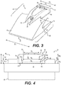
- Fig. 3 illustrates a perspective view of shroud 22, which may extend from adjacent shroud proximal end 70 to adjacent shroud distal end 72.
- Tip 44 of shroud 22 may extend from adjacent shroud proximal end 70 to adjacent tip end 74.
- Tip 44 may be generally wedge shaped with a thickness adjacent shroud proximal end 70, which may be smaller than a thickness of tip 44 adjacent tip end 74.
- Upper leg 46 of tip portion 40 may extend from tip end 74 to upper leg distal end 76, which may be disposed between tip end 74 and shroud distal end 72.
- Lower leg 48 of tip portion 40 may extend from tip end 74 to lower leg distal end 78, which may be disposed between tip end 74 and shroud distal end 72.
- Upper leg 46 may be spaced apart from lower leg 48, forming opening 50 between upper and lower legs 46, 48.
- Upper and lower legs 46, 48 may be wedge shaped.
- a thickness of upper leg 46 adjacent tip end 74 may be larger than a thickness of upper leg 46 adjacent upper leg distal end 76.
- a thickness of lower leg 48 adjacent tip end 74 may be larger than a thickness of lower leg 48 adjacent lower leg distal end 78.
- Tip 44, upper leg 46, and lower leg 48 may each have a width "W 1 .”
- Attachment portion 42 may be attached to tip portion 40. In one exemplary embodiment as illustrated in Fig. 3 , attachment portion 42 may be attached to upper leg 46 and may extend from adjacent tip end 74 to shroud distal end 72. Attachment portion 42 may have a width "W 2 " adjacent shroud distal end 72. In one exemplary embodiment as illustrated in Fig. 3 , width W 2 may be smaller than width W 1 . Attachment portion 42 may include a channel 80 (see dashed lines), which may extend from adjacent tip end 74 to shroud distal end 72. Channel 80 may have a generally inverted C-shape and may be configured to slidably engage with adapter 32 and slide compressor 60. Attachment portion 42 may also include channel front wall 82 adjacent tip end 74.
- Channel front wall 82 may include hole 52, which may be a through hole. Hole 52 may be sized to receive bolt 38, which may pass through hole 52 and extend into channel 80.
- attachment portion 42 may include opening 54, which may be configured to receive retainer plate 36. Opening 54 may be disposed adjacent shroud distal end 72 across a width of attachment portion 42. In one exemplary embodiment as illustrated in Fig. 3 , opening 54 may be disposed nearer to shroud distal end 72 compared to tip end 74. Opening 54 may have a width "W 3 ,” which may be smaller than a width W 2 of attachment portion 42. Width W 3 of opening 54 may be selected to allow retainer plate 36 to pass through opening 54 into channel 80.
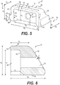
- Fig. 4 illustrates a rear view of shroud 22.
- channel 80 of attachment portion 42 may have a generally inverted C-shape having top wall 84, first leg 86, and second leg 88.
- First leg 86 may extend from top wall 84 towards edge 18 of work tool 10.
- First leg 86 may be disposed on first side 90 of channel 80 and may extend from top wall 84 to adjacent upper surface 92 of edge 18.
- Second leg 88 may extend from top wall 84 towards edge 18 of work tool 10.
- Second leg 88 may be disposed opposite first leg 86 on second side 94.
- Second leg 88 may extend from top wall 84 to adjacent upper surface 92 of edge 18.
- Channel 80 may have a height "H 1 " and may include lower recess 96 and upper recess 98, both of which together may form channel 80.
- Lower recess 96 may extend from adjacent upper surface 92 to first lower recess end 100 on first side 90 and second lower recess end 102 on second side 94.
- Lower recess 96 may have a height "HL 1 " adjacent first leg 86 and height "HL 2 " adjacent second leg 88. Heights HL 1 and HL 2 may be equal or unequal and may be smaller than height H 1 of channel 80.
- Lower recess 96 may have a width "W 4 " adjacent upper surface 92 and a width "W 5 " adjacent first and second lower recess ends 100, 102. In one exemplary embodiment as illustrated in Fig. 4 , width W 5 may be smaller than width W 4 giving lower recess 96 a generally inverted trapezoidal or dovetail shape.
- Upper recess 98 may extend from first and second lower recess ends 100, 102 to channel inner wall 104. Upper recess 98 may have a height "HU 1 " adjacent first leg 86 and a height "HU 2 " adjacent second leg 88. Heights HU 1 and HU 2 may be smaller than height H 1 of channel 80. Further, heights HU 1 , HU 2 , HL 1 , and HL 2 may be equal or unequal. Upper recess 98 may have a width W 6 adjacent top wall 84. In one exemplary embodiment as illustrated in Fig. 4 , width W 6 may be larger than width W 5 giving upper recess 98 a generally inverted trapezoidal or dovetail shape. Lower and upper recesses 96, 98 of channel 80 may be configured to slidably receive adapter 32 and slide compressor 60.
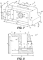
- Fig. 5 illustrates a perspective view of an exemplary disclosed adapter 32.
- Adapter 32 may include central block 106, first projection 108, and second projection 110.
- Central block 106 may include adapter front face 112 and adapter rear face 114 disposed opposite adapter front face 112.
- Adapter rear face 114 may be spaced apart from adapter front face 112.
- Central block 106 may include adapter bottom face 116 that may extend between adapter front face 112 and adapter rear face 114.
- Adapter bottom face 116 may be configured to abut against upper surface 92 of work tool 10.
- Central block 106 may include adapter top face 118 that may extend between adapter front face 112 and adapter rear face 114.
- Adapter top face 118 may be disposed opposite adapter bottom face 116.
- Adapter rear face 114 may be disposed generally orthogonal to adapter bottom face 116 and adapter top face 118.
- Adapter 32 may include first adapter side wall 120 and second adapter side wall 122.
- First adapter side wall 120 may be disposed on first side 124 of adapter 32 and may extend between adapter front face 112 and adapter rear face 114.
- Second adapter side wall 122 may be disposed on second side 126 of adapter 32 opposite first side 124.
- Second adapter side wall 122 may also extend between adapter front face 112 and adapter rear face 114.
- First and second adapter side walls 120, 122 may be disposed generally orthogonal to adapter front face 112, adapter rear face 114, adapter bottom face 116, and adapter top face 118.
- Adapter 32 may have a height "H 2 ,” which may be smaller than height H 1 of channel 80 to allow channel 80 to slidably engage with adapter 32.
- First projection 108 may extend outward from central block 106.
- First projection 108 may be disposed generally orthogonal to first adapter side wall 120.
- First projection may have a height "h 1 ,” between adapter bottom face 116 and first projection end 128. Height h 1 may be smaller than height H 2 of adapter 32.
- Second projection 110 may be disposed opposite first projection 108 and may extend outward from central block 106.
- Second projection 110 may be disposed generally orthogonal to second adapter side wall 122.
- Second projection may have a height "h 2 ,” between adapter bottom face 116 and second projection end 130. Height h 2 may be smaller than height H 2 of adapter 32. It is also contemplated that height h 2 may be the same as or different from height h 1 .
- First projection 108 may have a first lower side face 132, which may extend from adapter bottom face 116 to first projection end 128.
- First adapter side wall 120 may include a first upper side face 134, which may extend from first projection end 128 to adapter top face 118.
- Second projection 110 may have a second lower side face 136, which may extend from adapter bottom face 116 to second projection end 130.
- Second adapter side wall 122 may include second upper side face 138, which may extend from second projection end 130 to adapter top face 118.
- First and second lower side faces 132, 136 may be inclined relative to each other and relative to adapter bottom face 116 and adapter top face 118.
- first and second upper side faces 134, 138 may be inclined relative to each other and relative to adapter bottom face 116 and adapter top face 118.
- Adapter bottom face 116, first lower side face 132, and second lower side face 136 may be arranged so that first and second projections 108, 110 may form a dovetail mortice shape, which may be slidably received in lower recess 96 of channel 80.
- first and second upper side faces 134, 138 may be arranged so that central block 106 may form a dovetail mortice shape, which may be slidably received in upper recess 98 of channel 80.
- Adapter 32 may have a width "W 7 " adjacent adapter top face 118 and a width "Wg" between first and second projection ends 128, 130. Widths W 7 and W 8 may be less than widths W 6 and W 5 , respectively, to allow adapter 32 to be slidably received within channel 80 of shroud 22.
- Adapter 32 may include recess 140, which may extend from adapter rear face 114 into adapter 32 towards adapter front face 112.
- Recess 140 may have a recess base 142, which may be disposed generally parallel to adapter rear face 114.
- Recess 140 may have a depth "D 1 ,” between adapter rear face 114 and recess base 142. Depth D 1 may be smaller than a thickness "D 2 " of adapter 32.
- Recess 140 may have a height "H 3 " and a width "W 9 .” Height H 3 and width W 9 may be selected such that one end of spring damper 58 may be slidably retained within recess 140.
- Adapter 32 may include hole 56, which may extend from recess base 142 to adapter front face 112. In one exemplary embodiment as illustrated in Fig. 4 , hole 56 may be a through hole and may have a generally circular cross-section. It is contemplated, however, that hole 56 may be tapped to threadingly receive bolt
- Fig. 6 illustrates a vertical cross-sectional view of adapter 32.
- adapter front face 112 may be generally inclined relative to adapter bottom face 116, adapter top face 118, adapter rear face 114, and recess base 142.
- adapter front face 112 may be inclined towards adapter rear face 114 so that thickness D 2 of adapter 32 adj acent adapter top face 118 may be smaller than thickness "D 3 " of adapter 32 adjacent adapter bottom face 116.
- Angle of inclination ⁇ of adapter front face 112 relative to a vertical plane disposed generally parallel to adapter rear face 114 may range between about 15° to 30°.
- the terms "about” and “generally” indicate typical manufacturing tolerances and dimensional rounding.
- Fig. 7 illustrates a perspective view of an exemplary disclosed slide compressor 60.
- Slide compressor 60 may include central block 144, first projection 146, and second projection 148.
- Central block 144 may include compressor front face 150 and compressor rear face 152 disposed opposite compressor front face 150.
- Compressor rear face 152 may be spaced apart from compressor front face 150.
- Central block 144 may include compressor bottom face 154 that may extend between compressor front face 150 and compressor rear face 152.
- Compressor bottom face 154 may be configured to slidably engage with upper surface 92 of work tool 10.
- Central block 144 may include compressor top face 156 that may extend between compressor front face 150 and compressor rear face 152.
- Compressor top face 156 may be disposed opposite compressor bottom face 154.
- Compressor front face 150 may be disposed generally orthogonal to compressor bottom face 154 and compressor top face 156.
- Slide compressor 60 may include first compressor side wall 158 and second compressor side wall 160 disposed opposite first compressor side wall 158.
- First compressor side wall 158 may be disposed on first side 162 of slide compressor 60 and may extend between compressor front face 150 and compressor rear face 152.
- Second compressor side wall 160 may be disposed on second side 164 of slide compressor 60 opposite first side 162.
- Second compressor side wall 160 may extend between compressor front face 150 and compressor rear face 152.
- First and second compressor side walls 158, 160 may be disposed generally orthogonal to compressor front face 150, compressor rear face 152, compressor bottom face 154, and compressor top face 156.
- Slide compressor 60 may have a height "H 4 ,” which may be smaller than height H 1 of channel 80 to allow channel 80 to slidably engage with slide compressor 60.
- First projection 146 may extend outward from central block 144. First projection 146 may be disposed generally orthogonal to first compressor side wall 158. First projection may have a height "h 3 ,” between compressor bottom face 154 and first projection end 166. Height h 3 may be smaller than height H 4 of slide compressor 60. Second projection 148 may be disposed opposite first projection 146 and may extend outward from central block 144. Second projection 148 may be disposed generally orthogonal to second compressor side wall 160. Second projection may have a height "h 4 ,” between compressor bottom face 154 and second projection end 168. Height h 4 may be smaller than height H 2 . It is also contemplated that height h 4 may be the same as or different from height h 3 .
- First projection 146 may include first lower side face 170, which may extend from compressor bottom face 154 to first projection end 166.
- First compressor side wall 158 may include first upper side face 172, which may extend from first projection end 166 to compressor top face 156.
- Second projection 148 may have a second lower side face 174, which may extend from compressor bottom face 154 to second projection end 168.
- Second compressor side wall 160 may include second upper side face 176, which may extend from second projection end 168 to compressor top face 156.
- First and second lower side faces 170, 174 may be inclined relative to each other and relative to compressor bottom face 154 and compressor top face 156.
- first and second upper side faces 172, 176 may be inclined relative to each other and relative to compressor bottom face 154 and compressor top face 156.
- Compressor bottom face 154, first lower side face 170, and second lower side face 174 may be arranged so that first and second projections 146, 148 may form a dovetail mortice shape, which may be slidably received in lower recess 96 of channel 80.
- first and second upper side faces 172, 176 may be arranged so that central block 144 may form a dovetail mortice shape, which may be slidably received in upper recess 98 of channel 80.
- Slide compressor 60 may have a width "W 10 " adjacent compressor top face 156 and a width "W 11 " between first and second projection ends 166, 168. Widths W 10 and W 11 may be less than widths W6 and W5, respectively, to allow slide compressor 60 to be slidably received within channel 80 of shroud 22.
- Slide compressor 60 may include recess 178, which may extend from compressor front face 150 into slide compressor 60 towards compressor rear face 152.
- Recess 178 may have a recess base 180, which may be disposed generally parallel to compressor front face 150.
- Recess 178 may have a depth "D 4 ,” between compressor front face 150 and recess base 180. Depth D 4 may be smaller than a thickness "D 5 " of slide compressor 60.
- Recess 178 may have a height "H 5 " and a width "W 12 .” Height H 5 and width W 12 may be selected such that one end of spring damper 58 may be slidably retained within recess 178.
- height H 5 of recess 178 may be the same as or different from height H 3 of recess 140.
- width W 12 of recess 178 may be the same as or different from width W 9 of recess 140.
- Slide compressor 60 may include hole 66, which may extend between compressor front face 150 and compressor rear face 152. In one exemplary embodiment as illustrated in Fig. 7 , hole 66 may extend from recess base 180 to compressor rear face 152. Hole 66 may have a first hole portion 182, a second hole portion 184, and a third hole portion 186. First hole portion 182 and third hole portion 186 may be through holes and may have a generally circular cross-section. It is contemplated that first and third hole portions 182, 186 may be tapped to threadingly receive nut 62. Second hole portion 184 may have a generally non-circular cross-section. Slide compressor 60 may include slot 68 on compressor top face 156.
- Slot 68 may extend from compressor top face 156 towards compressor bottom face 154 and may intersect with hole 66. Slot 68 may intersect with second hole portion 184, which may be configured to slidably receive nut 62 through slot 68. The non-circular cross-section of second hole portion 184 may help prevent rotation of nut 62 within second hole portion 184. Slot 68 may be disposed nearer compressor rear face 152 relative to compressor front face 150. In one exemplary embodiment as illustrated in Fig. 7 , slot 68 may have a generally rectangular cross-section. Slot 68 may have a width "W 13 ,” which may be selected such that nut 62 may be receivable within slot 68.
- Fig. 8 illustrates a vertical cross-sectional view of slide compressor 60.
- compressor rear face 152 of slide compressor 60 may be generally inclined relative to compressor bottom face 154, compressor top face 156, compressor front face 150, and recess base 180.
- compressor rear face 152 may be inclined towards compressor front face 150 so that thickness D 5 of slide compressor 60 adjacent compressor top face 156 may be smaller than thickness "D 6 " of slide compressor 60 adjacent compressor bottom face 154.
- Angle of inclination ⁇ of compressor rear face 152 relative to a vertical plane disposed generally parallel to compressor rear face 152 may range between about 15° to 30°.
- first hole portion 182 may be disposed between recess base 180 and slot 68.
- First hole portion 182 may extend from recess base 180 to first hole portion end 188 disposed adjacent slot 68.
- First hole portion end 188 may be disposed between recess base 180 and compressor rear face 152.
- Second hole portion 184 may extend within slot 68 from first hole portion end 188 to second hole portion end 190, which may be disposed between first hole portion end 188 and compressor rear face 152.
- Third hole portion 186 may be disposed between slot 68 and compressor rear face 152.
- third hole portion 186 may extend from second hole portion end 190 to compressor rear face 152.
- first and third hole portions 182, 186 may have a generally circular cross-sections while second hole portion 184 may have a generally non-circular cross-section.
- Second hole portion 184 may have a width "D 7 ,” which may be selected to ensure that nut 62 may be slidably received in second hole portion 184.
- the non-circular cross-section of second hole portion 184 may help ensure that nut 62 does not rotate when placed within second hole portion 184.
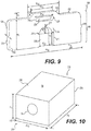
- Fig. 9 illustrates a perspective view of an exemplary disclosed retainer plate 36.
- Retainer plate 36 may have a retainer front face 192 disposed opposite retainer rear face 194.
- Retainer front and rear faces 192, 194 may be disposed generally parallel to each other and may be separated by a thickness T of retainer plate 36.
- thickness T may be generally uniform over an area of retainer front and rear faces 192, 194.
- Retainer plate 36 may include retainer portion 196 and pull out portion 198.
- Retainer portion 196 may have a generally rectangular shape and may include retainer bottom face 200, retainer top face 202, first retainer side face 204, and second retainer side face 206.
- Retainer bottom face 200 may extend from retainer front face 192 to retainer rear face 194.
- Retainer bottom face 200 may be disposed generally orthogonal to retainer front and rear faces 192, 194.
- Retainer top face 202 may extend from retainer front face 192 to retainer rear face 194.
- Retainer top face 202 may be disposed generally orthogonal to retainer front and rear faces 192, 194.
- First retainer side face 204 may extend from retainer front face 192 to retainer rear face 194 and between retainer bottom face 200 and retainer top face 202. First retainer side face 204 may be disposed generally orthogonal to retainer front and retainer rear faces 192, 194 and retainer top and bottom faces 200, 202. Likewise, second retainer side face 206 may extend from retainer front face 192 to retainer rear face 194 and extend between retainer bottom face 200 and retainer top face 202. Second retainer side face 206 may be disposed generally orthogonal to retainer front and retainer rear faces 192, 194 and retainer top and bottom faces 200, 202.
- retainer front face 192, retainer rear face 194, retainer bottom face 200, retainer top face 202, first retainer side face 204, and second retainer side face 206 may be disposed generally inclined relative to one or more of each other.
- Retainer portion 196 may have a width "W 14 " between first and second retainer side faces 204, 206 and a height "H 6 " between retainer bottom face 200 and retainer top face 202.
- Retainer portion 196 may include slot 208, which may extend through thickness T from retainer front face 192 to retainer rear face 194.
- slot 208 may be disposed generally midway between first and second retainer side faces 204, 206.
- Slot 208 may extend from retainer bottom face 200 toward retainer top face 202 to slot end 210, which may be disposed between retainer bottom face 200 and retainer top face 202.
- Slot 208 may include first slot portion 212 and second slot portion 214.
- First slot portion 212 may extend from retainer bottom face 200 to first slot portion end 216, which may be disposed between retainer bottom face 200 and slot end 210.
- First slot portion 212 may be a generally rectangular slot having a width "W 15 " and a height "H 7 .” It is contemplated, however, that first slot portion 212 may have a square shape or any other suitable shape known in the art. Width W 15 of first slot portion 212 may be smaller than width W 14 and may be selected so that width W 15 may be larger than a diameter of bolt 38. Second slot portion 214 may extend from first slot portion end 216 to slot end 210. Second slot portion 214 may have a generally semi-circular shape. In one exemplary embodiment as illustrated in Fig. 9 , a radius R of second slot portion 214 may be about half of width W 15 of first slot portion 212.
- Pull out portion 198 may have a generally trapezoidal shape and may extend outward from retainer top face 202 of retainer portion 196. Pull out portion 198 may have a width "W 16 ,” which may be smaller than width W 14 of retainer portion 196. Pull out portion 198 may be disposed generally midway between first and second retainer side faces 204, 206 of retainer portion 196. Pull out portion 198 may have a top wall 218, which may extend between retainer front face 192 and retainer rear face 194 of retainer plate 36. Top wall 218 may be disposed generally parallel to retainer top face 202 of retainer portion 196. Top wall 218 may be disposed at a height "H 7 " above retainer top face 202.
- Pull out portion 198 may have first side wall 220 and second side wall 222 disposed opposite first side wall 220.
- First and second side walls 220, 222 may extend from retainer front face 192 to retainer rear face 194 of retainer plate 36.
- First and second side walls 220, 222 may be disposed generally orthogonal to retainer front face 192 and retainer rear face 194 of retainer plate 36.
- First and second side walls 220, 222 may connect top wall 218 of pull out portion 198 with retainer top face 202 of retainer portion 196.
- First and second side walls 220, 222 may be inclined relative to top wall 218 and retainer top face 202 so that pull out portion 198 may have a generally trapezoidal shape.
- top wall 218 may have a width "W 17 ,” which may be smaller than width W 16 of pull out portion 198.
- Retainer plate 36 may include slot 224, which may be disposed between slot end 210 and top wall 218. Slot 224 may extend from retainer front face 192 to retainer rear face 194. Slot 224 may have a generally rectangular shape with generally semi-circular shaped slot ends 226. It is contemplated, however, that slot 224 may have an oblong, elliptical, circular, or any other type of shape known in the art. In one exemplary embodiment as illustrated in Fig. 9 , slot 224 may be disposed generally orthogonal to slot 208. Slot 224 may have a width "W 18 ,” which may be equal to, smaller than, or larger than widths W 15 , W 16 , and W 17 . In one exemplary embodiment as illustrated in Fig. 9 , slot 224 may be disposed partially in retainer portion 196 and partially in pull out portion 198. It is contemplated, however, that slot 224 may be disposed wholly in one of retainer portion 196 and pull out portion 198.
- Fig. 10 illustrates a perspective view of an exemplary disclosed spring damper 58.
- spring damper 58 may have a generally cuboidal shape having width "W 19 ,” thickness “D 8 ,” and height “H 8 .” It is contemplated, however, that spring damper 58 may have a cylindrical, conical, ellipsoidal, frusto-conical, or any other shape known in the art.
- Spring damper 58 may be configured to be disposed between adapter 32 and slide compressor 60.
- Spring damper 58 may extend from damper proximal end 228 to damper distal end 230.
- Spring damper 58 may be configured to be slidably attached to adapter 32 adjacent damper proximal end 228.
- spring damper 58 may be configured to be slidably attached to slide compressor 60 adjacent damper distal end 230.
- Spring damper 58 may include damper front face 232, damper rear face 234, and damper sides 236.
- Damper front face 232 may be disposed adjacent damper proximal end 228.
- Damper rear face 234 may be disposed opposite and spaced apart from damper front face 232.
- Damper rear face 234 may be disposed adjacent damper distal end 230.
- Damper sides 236 may extend from damper front face 232 to damper rear face 234. Damper front face 232 may be disposed generally parallel to damper rear face 234. Damper sides 236 may be disposed generally orthogonal to damper front face 232 and damper rear face 234.
- Damper front face 232 may have a generally rectangular shape, although other shapes are also contemplated.
- a size of damper front face 232 may be selected so that damper front face 232 may be receivable in recess 140 of adapter 32.
- Damper front face 232 may be configured to abut against recess base 142 of recess 140.
- Damper rear face 234 may have a generally rectangular shape, although other shapes are also contemplated.
- a size of damper rear face 234 may be selected so that damper rear face 234 may be receivable in recess 178 of slide compressor 60. Damper rear face 234 may be configured to abut against recess base 180 of recess 178.
- Spring damper 58 may include hole 64, which may extend from damper front face 232 to damper rear face 234. Hole 64 may be a through hole. It is contemplated that hole 64 may be tapped to threadingly receive bolt 38. Spring damper 58 may be made of elastomeric material, which may be configured to be compressed between adapter 32 and slide compressor 60. Additionally, or alternatively, spring damper 58 may include one or more spring members (not shown) disposed between damper front face 232 and damper rear face 234.
- Fig. 11 illustrates a cross-sectional view of an exemplary disclosed shroud retention system 30.
- lower leg 48 of shroud 22 may be disposed adjacent lower surface 238 of edge 18 of work tool 10.
- Upper leg 46 may be disposed adjacent upper surface 92 of edge 18, which may be disposed in opening 50 between upper leg 46 and lower leg 48.
- adapter 32 may be disposed on upper surface 92 of edge 18.
- adapter 32 may be fixedly attached to edge 18 via welded joints, fasteners, or using any other means of attachment known in the art.
- Adapter 32 may be disposed within channel 80, which may slidably engage with adapter 32.
- Channel front wall 82 of channel 80 may have an outer surface 240 and an inner surface 242. Hole 52 in attachment portion 42 of shroud 22 may extend from outer surface 240 to inner surface 242 of channel front wall 82. Adapter front face 112 of adapter 32 may be disposed opposite inner surface 242 of channel 80.
- Slide compressor 60 may also be disposed within channel 80, which may slidably engage with slide compressor 60.
- spring damper 58 may be disposed between adapter 32 and slide compressor 60 within channel 80.
- Damper front face 232 of spring damper 58 may be disposed opposite recess base 142 of recess 140 of adapter 32. Damper front face 232 may abut against recess base 142.
- Damper rear face 234 of spring damper 58 may be disposed opposite recess base 180 of recess 178 of slide compressor 60. Damper rear face 234 may abut against recess base 180.
- Holes 52, 56, 64, and 66 in shroud 22, adapter 32, spring damper 58, and slide compressor 60, respectively, may be axially aligned with nut 62 disposed in slot 68 of slide compressor 60, and may be configured to receive bolt 38.
- Nut 62 may be disposed within second hole portion 184 of hole 66.
- retainer plate 36 may be disposed within channel 80 in a locked position.
- retainer plate 36 may be disposed in channel 80 such that retainer front face 192 may abut against compressor rear face 152 of slide compressor 60.
- Top wall 84 of channel 80 may include channel inner surface 244, which may include notch 246.
- Notch 246 may be disposed adjacent opening 54 between opening 54 and hole 52.
- Notch 246 may include notch upper wall 248 and notch base wall 250.
- Pull out portion 198 of retainer plate 36 may slidably engage with notch 246 adjacent retainer top face 202.
- Top wall 218 of pull out portion 198 of retainer plate 36 may abut against notch upper wall 248, and retainer front face 192 of retainer plate 36 may abut against notch base wall 250.
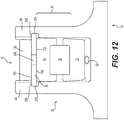
- Fig. 12 illustrates a bottom view of an exemplary disclosed shroud retention system 30.
- retainer plate 36 may be slidably attached to first and second legs 86, 88 of channel 80 and may be configured to retain spring assembly 34 between adapter 32 and retainer plate 36.
- Front face 196 of retainer plate 36 may abut compressor rear face 152 of slide compressor 60.
- first leg 86 of channel 80 may include first retainer slot 252 and second leg 88 of channel 80 may include second retainer slot 254.
- First retainer slot 252 may extend from opening 54 in top wall 84 of channel 80 to adjacent upper surface 92 (see dashed line in Fig. 4 ).
- second retainer slot 254 may extend from opening 54 in top wall 84 of channel 80 adjacent upper surface 92 of edge 18 to top wall 84 of channel 80 (see dashed line in Fig. 4 ).
- First and second retainer slots 252, 254 and opening 54 may allow retainer plate 36 to be inserted through opening 54 and be disposed in first and second retainer slots 252, 254.
- pull out portion 198 of retainer plate 36 may slidably engage with notch 246 in top wall 84 of channel 80 and retainer portion 196 of retainer plate 36 may abut against retainer slot walls 256 adjacent retainer bottom face 200.
- retainer rear face 194 may abut against retainer slot walls 256 of first and second retainer slots 252, 254 adjacent retainer bottom face 200.
- pull out portion 198 of retainer plate 36 may slidably engage with notch 246.
- retainer rear face 194 may engage with retainer slot walls 256 of first and second retainer slots 252, 254.
- the biasing force of spring damper 58 may help compressor rear face 152 move retainer plate 36 into its inclined and locked position within channel 80 as illustrated in Fig. 11 .
- Fig. 13 illustrates a perspective view of another exemplary embodiment of shroud 22.
- shroud 22 may also include one or more grooves 258 disposed on lower surface 260 of tip 44.
- Lower surface 260 may extend from tip edge 262, which may be disposed adjacent shroud proximal end 70, to adjacent lower leg distal end 78.
- Grooves 258 may be disposed adjacent tip edge 262 and may extend between first side face 264 of shroud 22 and second side face 266, which may be disposed opposite first side face 264.
- grooves 258 may have a width equal to width W 1 of tip 44.
- shroud 22 may include any number of grooves 258, which may be spaced from each other at equal or unequal distances. It is also contemplated that grooves 258 may be disposed parallel to or inclined relative to tip edge 262. Each groove 258 may have a generally rectangular shaped cross-section. Grooves 258 may be configured to slidingly or interferingly receive abrasion resistant materials, which may be attached to shroud 22 via fasteners, rivets, welded or brazed joints, or by any other method of attachment known in the art.
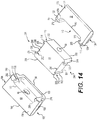
- Fig. 14 illustrates a perspective bottom view of exemplary embodiments of adapter 32, spring damper 58, and slide compressor 60.
- adapter 32 may include a dovetail shaped recess 140 between adapter rear face 114 and recess base 142.
- adapter 32 may include first adapter lip 268 disposed on first side 124 of adapter 32 and second adapter lip 270 disposed on second side 126 of adapter 32.
- First adapter lip 268 may extend into recess 140 from first adapter side wall 120 towards second adapter side wall 122.
- second adapter lip 270 may extend into recess 140 from second adapter side wall 122 towards first adapter side wall 120.
- First and second adapter lips 268, 270 may extend from adapter bottom face 116 and may have a height H 3 (see Fig. 3 ).
- recess 140 may include first side wall 272 disposed on first side 124 and second side wall 274 disposed on second side 126.
- First side wall 272 may extend between recess base 142 and first adapter lip 268.
- second side wall 274 may extend between recess base 142 and second adapter lip 270.
- First and second side walls 272, 274 may be disposed generally orthogonal to adapter bottom face 116.
- First and second side walls 272, 274 may be inclined relative to recess base 142 and relative to each other.
- First and second adapter lips 268, 270, first and second side walls 272, 274, and recess base 142 may form a generally dovetail shaped recess 140 in adapter 32.
- slide compressor 60 may include a dovetail shaped recess 178 between compressor front face 150 and recess base 180.
- slide compressor 60 may include first compressor lip 276 disposed on first side 162 of slide compressor 60 and second compressor lip 278 disposed on second side 164 of slide compressor 60.
- First compressor lip 276 may extend into recess 178 from first compressor side wall 158 towards second compressor side wall 160.
- second compressor lip 278 may extend into recess 178 from second compressor side wall 160 towards first compressor side wall 158.
- First and second compressor lips 276, 278 may extend from compressor bottom face 154 and may have a height H 5 (see Fig. 6 and second side wall 282 disposed on second side 164.
- First side wall 280 may extend between recess base 180 and first compressor lip 276.
- second side wall 282 may extend between recess base 180 and second compressor lip 278.
- First and second side walls 280, 282 may be disposed generally orthogonal to compressor bottom face 154.
- First and second side walls 280, 282 may be inclined relative to recess base 180 and relative to each other.
- First and second compressor lips 276, 278, first and second side walls 280, 282, and recess base 180 may form a generally dovetail shaped recess 178 in slide compressor 60.
- spring damper 58 may include first damper channel 290 and second damper channel 292.
- First damper channel 290 may be disposed on first side 294 of spring damper 58 and second damper channel may be disposed on second side 296 opposite first side 294.
- First side 294 of spring damper 58 may be disposed adjacent first side 124 of adapter 32 and first side 162 of slide compressor 60.
- second side 296 of spring damper 58 may be disposed adjacent second side 126 of adapter 32 and second side 164 of slide compressor 60.
- First damper channel 290 may extend from spring damper base 298 to spring damper top face 300.
- spring damper base 298 may be disposed generally coplanar with adapter bottom face 116 and compressor bottom face 154.
- First damper channel 290 may have side walls 302 and first channel base 304.
- Side walls 302 and first channel base 304 may be disposed generally orthogonal to spring damper base 298 and spring damper top face 300.
- Side walls 302 may be disposed generally parallel to each other and generally orthogonal to first channel base 304.
- Second damper channel 292 may extend from spring damper base 298 to spring damper top face 300.
- Second damper channel 292 may have side walls 306 and second channel base 308.
- Side walls 306 and second channel base 308 may be disposed generally orthogonal to spring damper base 298 and spring damper top face 300.
- Side walls 306 may be disposed generally parallel to each other and generally orthogonal to second channel base 308.
- adapter 32 may include first dovetail mortice 310 and second dovetail mortice 312.
- First dovetail mortice 310 may extend from damper front face 232 to side walls 302, 306 of first and second damper channels 290, 292, respectively.
- First dovetail mortice 310 may include mortice side walls 314, 316, which may extend from spring damper base 298 to spring damper top face 300.
- Mortice side wall 314 may be disposed on first side 294 and may extend from damper front face 232 to side wall 302 of first damper channel 290.
- Mortice side wall 316 may be disposed on second side 296 and may extend from damper front face 232 to side wall 306 of second damper channel 292.
- Mortice side walls 314, 316 may be disposed generally orthogonal to spring damper base 298 and spring damper top face 300. Mortice side walls 314, 316 may be generally inclined to each other. Damper front face 232, side walls 302, 306, and mortice side walls 314, 316 may give first dovetail mortice 310 a dovetail mortice shape. First dovetail mortice 310 may be configured to engage with dovetail shaped recess 140 in adapter 32 such that side wall 302 of first dovetail mortice 310 may engage with first adapter lip 268 and side wall 306 may engage with second adapter lip 270.
- Second dovetail mortice 312 may extend from damper front face 232 to side walls 302, 306 of first and second damper channels 290, 292, respectively.
- Second dovetail mortice 312 may include mortice side walls 318, 320, which may extend from spring damper base 298 to spring damper top face 300.
- Mortice side wall 318 may be disposed on first side 294 and may extend from damper rear face 234 to side wall 302 of first damper channel 290.
- Mortice side wall 320 may be disposed on second side 296 and may extend from damper rear face 234 to side wall 306 of second damper channel 292.
- Mortice side walls 318, 320 may be disposed generally orthogonal to spring damper base 298 and spring damper top face 300.
- Mortice side walls 318, 320 may be generally inclined to each other. Damper rear face 232, side walls 302, 306, and mortice side walls 318, 320 may give second dovetail mortice 312 a dovetail mortice shape. Second dovetail mortice 312 may be configured to engage with dovetail shaped recess 178 in slide compressor 60 such that side wall 302 of second dovetail mortice 312 may engage with first compressor lip 276, and side wall 306 may engage with second compressor lip 278.
- the disclosed shroud retention system may be used with various earth-working machines, such as hydraulic excavators, cable shovels, wheel loaders, front shovels, draglines, and bulldozers.
- the shroud retention system may be used to connect shrouds to work tools of these machines to help protect the work tool edges against wear. A method of retaining shroud 22 on work tool 10 will be described next.
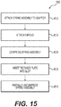
- Fig. 15 illustrates a method 1500 of retaining shroud 22 on work tool 10.
- Method 1500 may include a step of attaching spring assembly 34 to adapter 32 (Step 1502).
- spring damper 58 may be slidably inserted in recess 140 of adapter 32 adjacent damper proximal end 228 such that damper front face 232 abuts against recess base 142 of adapter 32.
- spring damper 58 may be placed adjacent adapter rear face 114 and may be pushed towards adapter 32 so that first dovetail mortice 310 may engage with first and second adapter lips 268, 270.
- slide compressor 60 may slidably attached to spring damper 58 adjacent damper distal end 230 such that damper rear face 234 abuts against recess base 180 of slide compressor 60.
- recess 178 of slide compressor 60 may be slidably engaged with second dovetail mortice 312 of spring damper 58 by engaging second dovetail mortice 312 and recess 178 adjacent spring damper top face 300.
- Slide compressor 60 may be slidingly pushed downward toward spring damper base 298 so that second dovetail mortice 312 of spring damper 58 engages with first and second compressor lips 276, 278.
- Nut 62 may be inserted into slot 68 of slide compressor 60 so that nut 62 is disposed in second hole portion 184 of hole 66 in slide compressor 60.
- Method 1500 may include a step of attaching shroud 22 (Step 1504).
- Attachment portion 42 of shroud 22 may be positioned and pushed rearward toward edge 18 so that adapter 32 and spring assembly 34 may be slidably received in channel 80 of attachment portion 42 of shroud 22.
- shroud 22 may be attached such that first and second projections 108, 110 of adapter 32 and first and second projections 146, 148 of slide compressor 60 may be slidably received in lower recess 96 of channel 80.
- first and second upper side faces 134, 138 of adapter 32 and first and second upper side faces 172, 176 of slide compressor 60 may be slidably received within upper recess 98 of channel 80.
- Method 1500 may include a step of compressing spring assembly 34 (Step 1506).
- bolt 38 may be inserted through holes 52, 56, 64, 66 of shroud 22, adapter 32, spring damper 58, and slide compressor 60, respectively, so that bolt 38 threadingly engages with nut 62 in slide compressor 60.
- Turning bolt 38 may cause slide compressor 60 to slidably move towards adapter 32, compressing spring damper 58
- Bolt 38 may be turned until opening 54 in attachment portion 42 of shroud 22 is located rearward of compressor rear face 152 of slide compressor 60. In this condition, opening 54 may be disposed between compressor rear face 152 of slide compressor 60 and shroud distal end 72.
- Method 1500 may include a step of inserting retainer plate 36 into opening 54 (Step 1508).
- Retainer plate 36 may be pushed into opening 54 so that first and second retainer side faces 204, 206 slidably engage with first and second retainer slots 252, 254.
- Retainer plate 36 may be pushed in through opening 54 until retainer bottom face 200 abuts against upper surface 92 of edge 18.
- Retainer plate 36 may in an unlocked position when inserted in this manner through opening 54 because it may be possible to pull retainer plate 36 out of opening 54.
- Method 1500 may include a step of partially uncompressing spring assembly 34 (Step 1510).
- bolt 38 may be turned to loosen bolt 38 from nut 62. Turning bolt 38 in this manner may allow slide compressor 60 to move away from adapter 32, uncompressing spring damper 58.
- spring damper 58 may exert a biasing force on slide compressor 60 pushing slide compressor 60 away from adapter 32. The biasing force of spring damper 58 may cause compressor rear face 152 of slide compressor 60 to push retainer front face 192 of retainer plate 36 so that retainer plate 36 may be tilted into its locked position.
- Tilting retainer plate 36 may cause retainer plate 36 to slidingly engage with notch 246 in channel 80 of shroud 22.
- retainer front face 192 of retainer plate 36 may abut against notch base wall 250 and top wall 218 of pull out portion 198 of retainer plate 36 may abut against notch upper wall 248.
- the biasing force of spring damper 58 and the angle of inclination of compressor rear face 152 of slide compressor 60 may help push retainer plate 36 against notch 246, preventing retainer plate 36 from being ejected out of opening 54.
- the biasing force of spring damper 58 and the angle of inclination of compressor rear face 152 may help retainer rear face 194 abut against retainer slot walls 256 adjacent retainer bottom face 200.
- retention system 30 may allow shroud 22 to be attached to work tool 10 without the use of any fasteners.
- bolt 38 may be completely removed from retention system 30.
- Bolt 38 may be reusable for assembly and/or disassembly of one or more shroud 22 on the same work tool 10.
- retention system 30 may help reduce the number of components in the assembly, which may help reduce the cost of operating work tool 10.
- shroud retention system 30 may help simplify the assembly process for shrouds 22 at a work site.
- a pry bar may be inserted through opening 54 to push retainer front face 192 of retainer plate 36 rearward so that retainer front face 192 and retainer top face 202 of retainer plate 36 may disengage from notch base wall 250 and notch upper wall 248, respectively.
- the pry bar may then be inserted into slot 224 in retainer plate 36 to pull retainer plate 36 out of opening 54.
- first and second dovetail mortices 310, 312, respectively, of spring damper 58 may prevent slide compressor 60 from being ejected rearward due to the biasing force of spring damper 58 when retailer plate 36 is removed from slot 224.
- shroud 22 may be slidably disengaged from slide compressor 60 and adapter 32 by pulling shroud 22 towards shroud proximal end 70 and away from edge 18 of work tool 10.
Landscapes
- Engineering & Computer Science (AREA)
- Mining & Mineral Resources (AREA)
- Civil Engineering (AREA)
- General Engineering & Computer Science (AREA)
- Structural Engineering (AREA)
- Mechanical Engineering (AREA)
- Structures Of Non-Positive Displacement Pumps (AREA)
- Portable Nailing Machines And Staplers (AREA)
Description
- The present disclosure relates generally to a shroud retention system and, more particularly, to a shroud retention system for a work tool.
- Earth-working machines, such as excavators, shovels, and wheel loaders, include ground engaging work tools that engage with and/or move a variety of earthen materials. These work tools often have one or more cutting tools or tooth assemblies mounted to an edge of the work tool, for example, to a lip of a bucket. The exposed portions of the work tool edge between adjacent tooth assemblies come into contact with the ground or the earthen materials and are subjected to extreme abrasion and impacts that cause them to wear. To prolong the useful life of the work tools, wear members or shrouds are attached to the work tools between adjacent tooth assemblies to protect the exposed portions of the work tool edge.
- Although the wear members protect the edge of the work tool, the wear members are still subject to severe abrasion and may need periodic repair or replacement. Removal and/or replacement of a wear member may require disassembly of the wear members from the edge of the work tool, and assembly of a repaired or a new wear member on the work tool. The machine must be taken out of service to perform such replacement or repair. The time required to disassemble and reassemble a wear member may be dictated by the mechanism used to retain the wear member on the work tool. It is desirable to have a retention system that allows for quick assembly and disassembly at a worksite to allow the machine to be returned to service as quickly as possible.
-
U.S. Patent No. 6,240,663 of Robinson, issued on June 5, 2001 ("the '663 patent"), discloses a resilient connection system for attaching a wear member to an excavating lip structure. In particular, the '663 patent discloses a wear member that has a front portion with two rearwardly extending legs including an upper leg which is disposed on top of a lip of a bucket and a lower leg, which is disposed below the lip. The '663 patent further discloses that a connection member is welded to the bucket. The connection member includes an upstanding boss that includes a circular opening. Likewise, the upper leg of the wear member of the '663 patent includes a projection. A fastener passing through the circular opening in the boss engages with the projection in the upper leg to attach the wear member to the connection member. The connection member of the '663 patent also includes two spring assemblies disposed on either side of the fastener. Each spring assembly includes a rod attached at one end to the connection member and a spring circumscribed around the rod. The spring is retained at the other end of the rod by a snap ring. The rods in each spring assembly of the '663 patent engage with openings in downwardly projecting bosses of the upper leg of the wear member so that the springs are retained between the bosses and the connection member. As the fastener is tightened, the spring assemblies of the ' 663 patent are compressed providing a biasing force to urge the wear member onto the lip. The '663 patent also discloses that a protective shroud is installed to protect the components of the retention system. - Although the '663 patent discloses a resilient wear member retention system, the disclosed retention system may not be optimal. For example, assembly of the wear member using the system of the '663 patent requires multiple features of the wear member to engage with corresponding features of the connection member, making the assembly cumbersome. In particular, the system of the '663 patent requires a projection in the wear member leg to engage with a fastener attached to the connection member, while simultaneously requiring two bosses in the leg to engage with spring assemblies in the connection member. Disassembly of the wear member may also be cumbersome because of the need to loosen the fastener and disengage the wear member from the fastener and the two spring assemblies for removal. Further, the retention system of the '663 member requires a fastener, two separate spring assemblies, and a protective shroud. The large number of parts required for assembly may increase the cost of manufacturing and maintaining the retention system of the '663 patent.
- The shroud retention system of the present disclosure solves one or more of the problems set forth above and/or other problems of the prior art.
-
WO 2013/122561 A1 discloses an attachment system for use with an excavation implement, including a retainer which secures a wear member to a lip of the excavation implement. The retainer is fixedly attached to the lip, and a biasing device is retained within the retainer. The biasing device biases the wear member toward the lip. A method of attaching a wear member to a lip of an excavation implement includes installing a biasing device in a retainer fixedly secured to the lip, and then positioning the wear member on the lip. -
WO 2012/016251 A1 discloses a wear part system including an adaptor configured and dimensioned to be attached to a portion of a piece of equipment. The adaptor includes a passage extending between two opposed sides thereof. -
US 2005/0229441 A1 discloses an attachment system for connecting a first member such as a lip plate of a mechanical digging device to a second member such as a ground engaging tool. -
WO 2016/135360 A1 discloses a device for attaching a wear or protection element to a shovel of a soil-shifting machine. - In one aspect, the present disclosure is directed to a shroud retention system for a work tool. The shroud retention system includes an adapter attached to the work tool. The shroud retention system further includes a spring assembly attached to the adapter. The shroud retention system also includes a shroud, which includes a channel configured to slidably receive the adapter and the spring assembly. The channel includes a retainer slot. The shroud retention system includes a retainer plate disposed in the retainer slot. The retainer plate is movable from an unlocked position, in which the retainer plate can be pulled out of the retainer slot, into a locked position by the spring assembly to attach the shroud to the work tool without the use of any fasteners.
- In yet another aspect, the present disclosure is direct to a work tool. The work tool includes a first side wall and a second side wall spaced apart from the first side wall. The work tool further includes a primary wall, which includes an edge extending from the first side wall to the second side wall, and a shroud retention system in accordance with the above aspect. The adapter of the shroud retention system is attached to the primary wall.
-
-
Fig. 1 is an illustration of an exemplary work tool; -
Fig. 2 is an illustration of an exemplary shroud retention system for the work tool ofFig. 1 ; -
Fig. 3 is a perspective view of an exemplary shroud for the shroud retention system ofFig. 2 ; -
Fig. 4 is rear view of the exemplary shroud ofFig. 3 ; -
Fig. 5 is a perspective view of an exemplary adapter for the shroud retention system ofFig. 2 ; -
Fig. 6 is a cross-sectional view of the exemplary adapter ofFig. 5 ; -
Fig. 7 is a perspective view of an exemplary slide compressor for the shroud retention system ofFig. 2 ; -
Fig. 8 is a cross-sectional view of the exemplary slide compressor ofFig. 7 ; -
Fig. 9 is a perspective view of an exemplary retainer plate for the shroud retention system ofFig. 2 ; -
Fig. 10 is a perspective view of an exemplary spring damper for the shroud retention system ofFig. 2 ; -
Fig. 11 is a cross-sectional view of the exemplary shroud retention system ofFig. 2 ; -
Fig. 12 is a bottom view of the exemplary shroud retention system ofFig. 2 ; -
Fig. 13 is a perspective view of another exemplary shroud for the shroud retention system ofFig. 2 ; -
Fig. 14 is a perspective bottom view of an exemplary adapter, spring damper, and slide compressor for the shroud retention system ofFig. 2 ; and -
Fig. 15 is a flow-chart of an exemplary method of retaining the shroud ofFig. 3 using the shroud retention system ofFig. 2 . -
Fig. 1 illustrates anexemplary work tool 10 for a machine (not shown).Work tool 10 may embody any device used to perform a task assigned to the machine. For example,work tool 10 may be a bucket (shown inFig. 1 ), a blade, a shovel, a crusher, a grapple, a ripper, or any other material moving device known in the art.Work tool 10 may includeside walls primary wall 16, which may form a bottom ofwork tool 10.Primary wall 16 may extend fromside wall 12 toside wall 14.Primary wall 16 ofwork tool 10 may also include edge 18 (seeFig. 2 ), extending betweenside walls Edge 18 may be detachable fromwork tool 10 or it may be a fixed component ofwork tool 10. -
Work tool 10 may include a plurality of shrouds 22 (or wear members) attached to edge 18. Eachshroud 22 may be configured to protectedge 18 from abrasion and wear by reducing or preventing contact of an exposed portion ofedge 18 with earthen materials. In some exemplary embodiments, shrouds 22 may be disposed between adjacent tool assemblies (not shown) attached to edge 18 to protect a portion ofedge 18 between the adjacent tool assemblies from abrasion and wear. - For the purposes of this disclosure, attention will be focused on attachment of
shrouds 22 to worktool 10. It is contemplated, however, that the attachment methods and structures presented in this disclosure may be equally utilized with tool assemblies, other wear components, and/or with any other wear components known in the art. -
Fig. 2 illustrates an exemplaryshroud retention system 30 for attachingshroud 22 to worktool 10.Shroud retention system 30 may includeadapter 32,spring assembly 34,retainer plate 36, andbolt 38.Shroud 22 may includetip portion 40 andattachment portion 42.Tip portion 40 may be generally U-shaped and may includetip 44,upper leg 46, andlower leg 48. Upper andlower legs tip 44. Upper andlower legs edge 18 ofwork tool 10.Attachment portion 42 may be attached toupper leg 46 oftip portion 40. Like upper andlower legs attachment portion 42 may extend in a direction away fromtip 44.Attachment portion 42 may includehole 52 configured to receivebolt 38.Attachment portion 42 may also include opening 54 configured to slidably receiveretainer plate 36. -
Adapter 32 may be attached toprimary wall 16 ofwork tool 10.Adapter 32 may be configured to be slidably received inattachment portion 42.Adapter 32 may includehole 56 configured to receivebolt 38.Spring assembly 34 may be disposedadjacent adapter 32.Spring assembly 34 may be attached toadapter 32 and may includespring damper 58,slide compressor 60, andnut 62. As illustrated inFig. 2 ,spring damper 58 may be disposed betweenadapter 32 andslide compressor 60.Spring damper 58 may includehole 64 configured to receivebolt 38.Slide compressor 60 may be configured to be slidably received inattachment portion 42.Slide compressor 60 may includehole 66 configured to receivebolt 38.Slide compressor 60 may also includeslot 68, which may be configured to receivenut 62.Bolt 38 may pass throughhole 52 inattachment portion 42 ofshroud 22,hole 56 inadapter 32,hole 64 inspring damper 58, andhole 66 inslide compressor 60 to threadingly engage withnut 62 disposed withinslot 68.Slide compressor 60 may be configured to slidably movable relative toadapter 32. For example,slide compressor 60 may be configured to slidably move towardsadapter 32 whenbolt 38 is turned to engage withnut 62, compressingspring damper 58 disposed betweenadapter 32 andslide compressor 60. -
Fig. 3 illustrates a perspective view ofshroud 22, which may extend from adjacent shroudproximal end 70 to adjacent shrouddistal end 72.Tip 44 ofshroud 22 may extend from adjacent shroudproximal end 70 toadjacent tip end 74.Tip 44 may be generally wedge shaped with a thickness adjacent shroudproximal end 70, which may be smaller than a thickness oftip 44adjacent tip end 74.Upper leg 46 oftip portion 40 may extend fromtip end 74 to upper legdistal end 76, which may be disposed betweentip end 74 and shrouddistal end 72.Lower leg 48 oftip portion 40 may extend fromtip end 74 to lower legdistal end 78, which may be disposed betweentip end 74 and shrouddistal end 72.Upper leg 46 may be spaced apart fromlower leg 48, formingopening 50 between upper andlower legs lower legs upper leg 46adjacent tip end 74 may be larger than a thickness ofupper leg 46 adjacent upper legdistal end 76. Likewise, a thickness oflower leg 48adjacent tip end 74 may be larger than a thickness oflower leg 48 adjacent lower legdistal end 78.Tip 44,upper leg 46, andlower leg 48 may each have a width "W1." -
Attachment portion 42 may be attached to tipportion 40. In one exemplary embodiment as illustrated inFig. 3 ,attachment portion 42 may be attached toupper leg 46 and may extend fromadjacent tip end 74 to shrouddistal end 72.Attachment portion 42 may have a width "W2" adjacent shrouddistal end 72. In one exemplary embodiment as illustrated inFig. 3 , width W2 may be smaller than width W1. Attachment portion 42 may include a channel 80 (see dashed lines), which may extend fromadjacent tip end 74 to shrouddistal end 72.Channel 80 may have a generally inverted C-shape and may be configured to slidably engage withadapter 32 andslide compressor 60.Attachment portion 42 may also includechannel front wall 82adjacent tip end 74. Channelfront wall 82 may includehole 52, which may be a through hole.Hole 52 may be sized to receivebolt 38, which may pass throughhole 52 and extend intochannel 80. As also illustrated inFig. 3 ,attachment portion 42 may include opening 54, which may be configured to receiveretainer plate 36.Opening 54 may be disposed adjacent shrouddistal end 72 across a width ofattachment portion 42. In one exemplary embodiment as illustrated inFig. 3 , opening 54 may be disposed nearer to shrouddistal end 72 compared to tipend 74.Opening 54 may have a width "W3," which may be smaller than a width W2 ofattachment portion 42. Width W3 of opening 54 may be selected to allowretainer plate 36 to pass through opening 54 intochannel 80. -
Fig. 4 illustrates a rear view ofshroud 22. As illustrated inFig. 4 ,channel 80 ofattachment portion 42 may have a generally inverted C-shape havingtop wall 84,first leg 86, andsecond leg 88.First leg 86 may extend fromtop wall 84 towardsedge 18 ofwork tool 10.First leg 86 may be disposed onfirst side 90 ofchannel 80 and may extend fromtop wall 84 to adjacentupper surface 92 ofedge 18.Second leg 88 may extend fromtop wall 84 towardsedge 18 ofwork tool 10.Second leg 88 may be disposed oppositefirst leg 86 onsecond side 94.Second leg 88 may extend fromtop wall 84 to adjacentupper surface 92 ofedge 18.Channel 80 may have a height "H1" and may includelower recess 96 andupper recess 98, both of which together may formchannel 80.Lower recess 96 may extend from adjacentupper surface 92 to firstlower recess end 100 onfirst side 90 and secondlower recess end 102 onsecond side 94.Lower recess 96 may have a height "HL1" adjacentfirst leg 86 and height "HL2" adjacentsecond leg 88. Heights HL1 and HL2 may be equal or unequal and may be smaller than height H1 ofchannel 80.Lower recess 96 may have a width "W4" adjacentupper surface 92 and a width "W5" adjacent first and second lower recess ends 100, 102. In one exemplary embodiment as illustrated inFig. 4 , width W5 may be smaller than width W4 giving lower recess 96 a generally inverted trapezoidal or dovetail shape. -
Upper recess 98 may extend from first and second lower recess ends 100, 102 to channelinner wall 104.Upper recess 98 may have a height "HU1" adjacentfirst leg 86 and a height "HU2" adjacentsecond leg 88. Heights HU1 and HU2 may be smaller than height H1 ofchannel 80. Further, heights HU1, HU2, HL1, and HL2 may be equal or unequal.Upper recess 98 may have a width W6 adjacenttop wall 84. In one exemplary embodiment as illustrated inFig. 4 , width W6 may be larger than width W5 giving upper recess 98 a generally inverted trapezoidal or dovetail shape. Lower andupper recesses channel 80 may be configured to slidably receiveadapter 32 andslide compressor 60. -
Fig. 5 illustrates a perspective view of an exemplary disclosedadapter 32.Adapter 32 may includecentral block 106,first projection 108, andsecond projection 110.Central block 106 may includeadapter front face 112 and adapterrear face 114 disposed oppositeadapter front face 112. Adapterrear face 114 may be spaced apart fromadapter front face 112.Central block 106 may includeadapter bottom face 116 that may extend between adapterfront face 112 and adapterrear face 114.Adapter bottom face 116 may be configured to abut againstupper surface 92 ofwork tool 10.Central block 106 may includeadapter top face 118 that may extend between adapterfront face 112 and adapterrear face 114.Adapter top face 118 may be disposed oppositeadapter bottom face 116. Adapterrear face 114 may be disposed generally orthogonal toadapter bottom face 116 and adaptertop face 118. -
Adapter 32 may include firstadapter side wall 120 and secondadapter side wall 122. Firstadapter side wall 120 may be disposed onfirst side 124 ofadapter 32 and may extend between adapterfront face 112 and adapterrear face 114. Secondadapter side wall 122 may be disposed onsecond side 126 ofadapter 32 oppositefirst side 124. Secondadapter side wall 122 may also extend between adapterfront face 112 and adapterrear face 114. First and secondadapter side walls adapter front face 112, adapterrear face 114,adapter bottom face 116, and adaptertop face 118.Adapter 32 may have a height "H2," which may be smaller than height H1 ofchannel 80 to allowchannel 80 to slidably engage withadapter 32. -
First projection 108 may extend outward fromcentral block 106.First projection 108 may be disposed generally orthogonal to firstadapter side wall 120. First projection may have a height "h1," between adapterbottom face 116 andfirst projection end 128. Height h1 may be smaller than height H2 ofadapter 32.Second projection 110 may be disposed oppositefirst projection 108 and may extend outward fromcentral block 106.Second projection 110 may be disposed generally orthogonal to secondadapter side wall 122. Second projection may have a height "h2," between adapterbottom face 116 andsecond projection end 130. Height h2 may be smaller than height H2 ofadapter 32. It is also contemplated that height h2 may be the same as or different from height h1. -
First projection 108 may have a firstlower side face 132, which may extend fromadapter bottom face 116 tofirst projection end 128. Firstadapter side wall 120 may include a firstupper side face 134, which may extend fromfirst projection end 128 toadapter top face 118.Second projection 110 may have a secondlower side face 136, which may extend fromadapter bottom face 116 tosecond projection end 130. Secondadapter side wall 122 may include secondupper side face 138, which may extend fromsecond projection end 130 toadapter top face 118. First and second lower side faces 132, 136 may be inclined relative to each other and relative toadapter bottom face 116 and adaptertop face 118. Likewise, first and second upper side faces 134, 138 may be inclined relative to each other and relative toadapter bottom face 116 and adaptertop face 118.Adapter bottom face 116, firstlower side face 132, and secondlower side face 136 may be arranged so that first andsecond projections lower recess 96 ofchannel 80. Likewise, first and second upper side faces 134, 138 may be arranged so thatcentral block 106 may form a dovetail mortice shape, which may be slidably received inupper recess 98 ofchannel 80.Adapter 32 may have a width "W7" adjacentadapter top face 118 and a width "Wg" between first and second projection ends 128, 130. Widths W7 and W8 may be less than widths W6 and W5, respectively, to allowadapter 32 to be slidably received withinchannel 80 ofshroud 22. -
Adapter 32 may includerecess 140, which may extend from adapterrear face 114 intoadapter 32 towardsadapter front face 112. Recess 140 may have arecess base 142, which may be disposed generally parallel to adapterrear face 114. Recess 140 may have a depth "D1," between adapterrear face 114 andrecess base 142. Depth D1 may be smaller than a thickness "D2" ofadapter 32. Recess 140 may have a height "H3" and a width "W9." Height H3 and width W9 may be selected such that one end ofspring damper 58 may be slidably retained withinrecess 140.Adapter 32 may includehole 56, which may extend fromrecess base 142 toadapter front face 112. In one exemplary embodiment as illustrated inFig. 4 ,hole 56 may be a through hole and may have a generally circular cross-section. It is contemplated, however, thathole 56 may be tapped to threadingly receivebolt 38. -
Fig. 6 illustrates a vertical cross-sectional view ofadapter 32. As illustrated inFig. 6 ,adapter front face 112 may be generally inclined relative toadapter bottom face 116,adapter top face 118, adapterrear face 114, andrecess base 142. In one exemplary embodiment,adapter front face 112 may be inclined towards adapterrear face 114 so that thickness D2 ofadapter 32 adj acent adaptertop face 118 may be smaller than thickness "D3" ofadapter 32 adjacentadapter bottom face 116. Angle of inclination θ ofadapter front face 112 relative to a vertical plane disposed generally parallel to adapterrear face 114 may range between about 15° to 30°. As used in this disclosure, the terms "about" and "generally" indicate typical manufacturing tolerances and dimensional rounding. -
Fig. 7 illustrates a perspective view of an exemplary disclosedslide compressor 60.Slide compressor 60 may includecentral block 144,first projection 146, andsecond projection 148.Central block 144 may includecompressor front face 150 and compressorrear face 152 disposed oppositecompressor front face 150. Compressorrear face 152 may be spaced apart fromcompressor front face 150.Central block 144 may includecompressor bottom face 154 that may extend between compressorfront face 150 and compressorrear face 152. Compressorbottom face 154 may be configured to slidably engage withupper surface 92 ofwork tool 10.Central block 144 may includecompressor top face 156 that may extend between compressorfront face 150 and compressorrear face 152. Compressortop face 156 may be disposed oppositecompressor bottom face 154.Compressor front face 150 may be disposed generally orthogonal tocompressor bottom face 154 and compressortop face 156. -
Slide compressor 60 may include firstcompressor side wall 158 and secondcompressor side wall 160 disposed opposite firstcompressor side wall 158. Firstcompressor side wall 158 may be disposed onfirst side 162 ofslide compressor 60 and may extend between compressorfront face 150 and compressorrear face 152. Secondcompressor side wall 160 may be disposed onsecond side 164 ofslide compressor 60 oppositefirst side 162. Secondcompressor side wall 160 may extend between compressorfront face 150 and compressorrear face 152. First and secondcompressor side walls compressor front face 150, compressorrear face 152,compressor bottom face 154, and compressortop face 156.Slide compressor 60 may have a height "H4," which may be smaller than height H1 ofchannel 80 to allowchannel 80 to slidably engage withslide compressor 60. -
First projection 146 may extend outward fromcentral block 144.First projection 146 may be disposed generally orthogonal to firstcompressor side wall 158. First projection may have a height "h3," between compressorbottom face 154 andfirst projection end 166. Height h3 may be smaller than height H4 ofslide compressor 60.Second projection 148 may be disposed oppositefirst projection 146 and may extend outward fromcentral block 144.Second projection 148 may be disposed generally orthogonal to secondcompressor side wall 160. Second projection may have a height "h4," between compressorbottom face 154 andsecond projection end 168. Height h4 may be smaller than height H2. It is also contemplated that height h4 may be the same as or different from height h3. -
First projection 146 may include firstlower side face 170, which may extend fromcompressor bottom face 154 tofirst projection end 166. Firstcompressor side wall 158 may include firstupper side face 172, which may extend fromfirst projection end 166 tocompressor top face 156.Second projection 148 may have a secondlower side face 174, which may extend fromcompressor bottom face 154 tosecond projection end 168. Secondcompressor side wall 160 may include secondupper side face 176, which may extend fromsecond projection end 168 tocompressor top face 156. First and second lower side faces 170, 174 may be inclined relative to each other and relative tocompressor bottom face 154 and compressortop face 156. Likewise, first and second upper side faces 172, 176 may be inclined relative to each other and relative tocompressor bottom face 154 and compressortop face 156. Compressorbottom face 154, firstlower side face 170, and secondlower side face 174 may be arranged so that first andsecond projections lower recess 96 ofchannel 80. Likewise, first and second upper side faces 172, 176 may be arranged so thatcentral block 144 may form a dovetail mortice shape, which may be slidably received inupper recess 98 ofchannel 80.Slide compressor 60 may have a width "W10" adjacentcompressor top face 156 and a width "W11" between first and second projection ends 166, 168. Widths W10 and W11 may be less than widths W6 and W5, respectively, to allowslide compressor 60 to be slidably received withinchannel 80 ofshroud 22. -
Slide compressor 60 may includerecess 178, which may extend fromcompressor front face 150 intoslide compressor 60 towards compressorrear face 152. Recess 178 may have arecess base 180, which may be disposed generally parallel tocompressor front face 150. Recess 178 may have a depth "D4," between compressorfront face 150 andrecess base 180. Depth D4 may be smaller than a thickness "D5" ofslide compressor 60. Recess 178 may have a height "H5" and a width "W12." Height H5 and width W12 may be selected such that one end ofspring damper 58 may be slidably retained withinrecess 178. It is contemplated that height H5 ofrecess 178 may be the same as or different from height H3 ofrecess 140. Likewise, it is contemplated that width W12 ofrecess 178 may be the same as or different from width W9 ofrecess 140. -
Slide compressor 60 may includehole 66, which may extend between compressorfront face 150 and compressorrear face 152. In one exemplary embodiment as illustrated inFig. 7 ,hole 66 may extend fromrecess base 180 to compressorrear face 152.Hole 66 may have afirst hole portion 182, asecond hole portion 184, and athird hole portion 186.First hole portion 182 andthird hole portion 186 may be through holes and may have a generally circular cross-section. It is contemplated that first andthird hole portions nut 62.Second hole portion 184 may have a generally non-circular cross-section.Slide compressor 60 may includeslot 68 oncompressor top face 156.Slot 68 may extend from compressortop face 156 towardscompressor bottom face 154 and may intersect withhole 66.Slot 68 may intersect withsecond hole portion 184, which may be configured to slidably receivenut 62 throughslot 68. The non-circular cross-section ofsecond hole portion 184 may help prevent rotation ofnut 62 withinsecond hole portion 184.Slot 68 may be disposed nearer compressorrear face 152 relative tocompressor front face 150. In one exemplary embodiment as illustrated inFig. 7 ,slot 68 may have a generally rectangular cross-section.Slot 68 may have a width "W13," which may be selected such thatnut 62 may be receivable withinslot 68. -
Fig. 8 illustrates a vertical cross-sectional view ofslide compressor 60. As illustrated inFig. 6 , compressorrear face 152 ofslide compressor 60 may be generally inclined relative tocompressor bottom face 154,compressor top face 156,compressor front face 150, andrecess base 180. In one exemplary embodiment, compressorrear face 152 may be inclined towardscompressor front face 150 so that thickness D5 ofslide compressor 60 adjacentcompressor top face 156 may be smaller than thickness "D6" ofslide compressor 60 adjacentcompressor bottom face 154. Angle of inclination φ of compressorrear face 152 relative to a vertical plane disposed generally parallel to compressorrear face 152 may range between about 15° to 30°. - As also illustrated in
Fig. 8 ,first hole portion 182 may be disposed betweenrecess base 180 andslot 68.First hole portion 182 may extend fromrecess base 180 to firsthole portion end 188 disposedadjacent slot 68. Firsthole portion end 188 may be disposed betweenrecess base 180 and compressorrear face 152.Second hole portion 184 may extend withinslot 68 from firsthole portion end 188 to secondhole portion end 190, which may be disposed between firsthole portion end 188 and compressorrear face 152.Third hole portion 186 may be disposed betweenslot 68 and compressorrear face 152. For example,third hole portion 186 may extend from secondhole portion end 190 to compressorrear face 152. As discussed above, first andthird hole portions second hole portion 184 may have a generally non-circular cross-section.Second hole portion 184 may have a width "D7," which may be selected to ensure thatnut 62 may be slidably received insecond hole portion 184. The non-circular cross-section ofsecond hole portion 184 may help ensure thatnut 62 does not rotate when placed withinsecond hole portion 184. -
Fig. 9 illustrates a perspective view of an exemplary disclosedretainer plate 36.Retainer plate 36 may have aretainer front face 192 disposed opposite retainerrear face 194. Retainer front and rear faces 192, 194 may be disposed generally parallel to each other and may be separated by a thickness T ofretainer plate 36. In one exemplary embodiment as illustrated inFig. 9 , thickness T may be generally uniform over an area of retainer front and rear faces 192, 194. -
Retainer plate 36 may includeretainer portion 196 and pull outportion 198.Retainer portion 196 may have a generally rectangular shape and may include retainerbottom face 200,retainer top face 202, first retainer side face 204, and secondretainer side face 206. Retainerbottom face 200 may extend fromretainer front face 192 to retainerrear face 194. Retainerbottom face 200 may be disposed generally orthogonal to retainer front and rear faces 192, 194. Retainertop face 202 may extend fromretainer front face 192 to retainerrear face 194. Retainertop face 202 may be disposed generally orthogonal to retainer front and rear faces 192, 194. First retainer side face 204 may extend fromretainer front face 192 to retainerrear face 194 and between retainerbottom face 200 and retainertop face 202. First retainer side face 204 may be disposed generally orthogonal to retainer front and retainer rear faces 192, 194 and retainer top and bottom faces 200, 202. Likewise, secondretainer side face 206 may extend fromretainer front face 192 to retainerrear face 194 and extend between retainerbottom face 200 and retainertop face 202. Secondretainer side face 206 may be disposed generally orthogonal to retainer front and retainer rear faces 192, 194 and retainer top and bottom faces 200, 202. It is contemplated, however, thatretainer front face 192, retainerrear face 194,retainer bottom face 200,retainer top face 202, first retainer side face 204, and secondretainer side face 206 may be disposed generally inclined relative to one or more of each other.Retainer portion 196 may have a width "W14" between first and second retainer side faces 204, 206 and a height "H6" between retainerbottom face 200 and retainertop face 202. -
Retainer portion 196 may includeslot 208, which may extend through thickness T fromretainer front face 192 to retainerrear face 194. In one exemplary embodiment as illustrated inFig. 9 ,slot 208 may be disposed generally midway between first and second retainer side faces 204, 206.Slot 208 may extend from retainerbottom face 200 toward retainertop face 202 to slotend 210, which may be disposed between retainerbottom face 200 and retainertop face 202.Slot 208 may includefirst slot portion 212 andsecond slot portion 214.First slot portion 212 may extend from retainerbottom face 200 to firstslot portion end 216, which may be disposed between retainerbottom face 200 andslot end 210.First slot portion 212 may be a generally rectangular slot having a width "W15" and a height "H7." It is contemplated, however, thatfirst slot portion 212 may have a square shape or any other suitable shape known in the art. Width W15 offirst slot portion 212 may be smaller than width W14 and may be selected so that width W15 may be larger than a diameter ofbolt 38.Second slot portion 214 may extend from firstslot portion end 216 to slotend 210.Second slot portion 214 may have a generally semi-circular shape. In one exemplary embodiment as illustrated inFig. 9 , a radius R ofsecond slot portion 214 may be about half of width W15 offirst slot portion 212. - Pull out
portion 198 may have a generally trapezoidal shape and may extend outward from retainertop face 202 ofretainer portion 196. Pull outportion 198 may have a width "W16," which may be smaller than width W14 ofretainer portion 196. Pull outportion 198 may be disposed generally midway between first and second retainer side faces 204, 206 ofretainer portion 196. Pull outportion 198 may have atop wall 218, which may extend between retainerfront face 192 and retainerrear face 194 ofretainer plate 36.Top wall 218 may be disposed generally parallel to retainertop face 202 ofretainer portion 196.Top wall 218 may be disposed at a height "H7" aboveretainer top face 202. - Pull out
portion 198 may havefirst side wall 220 and second side wall 222 disposed oppositefirst side wall 220. First andsecond side walls 220, 222 may extend fromretainer front face 192 to retainerrear face 194 ofretainer plate 36. First andsecond side walls 220, 222 may be disposed generally orthogonal toretainer front face 192 and retainerrear face 194 ofretainer plate 36. First andsecond side walls 220, 222 may connecttop wall 218 of pull outportion 198 with retainertop face 202 ofretainer portion 196. First andsecond side walls 220, 222 may be inclined relative totop wall 218 and retainertop face 202 so that pull outportion 198 may have a generally trapezoidal shape. For exampletop wall 218 may have a width "W17," which may be smaller than width W16 of pull outportion 198. -
Retainer plate 36 may includeslot 224, which may be disposed betweenslot end 210 andtop wall 218.Slot 224 may extend fromretainer front face 192 to retainerrear face 194.Slot 224 may have a generally rectangular shape with generally semi-circular shaped slot ends 226. It is contemplated, however, thatslot 224 may have an oblong, elliptical, circular, or any other type of shape known in the art. In one exemplary embodiment as illustrated inFig. 9 ,slot 224 may be disposed generally orthogonal to slot 208.Slot 224 may have a width "W18," which may be equal to, smaller than, or larger than widths W15, W16, and W17. In one exemplary embodiment as illustrated inFig. 9 ,slot 224 may be disposed partially inretainer portion 196 and partially in pull outportion 198. It is contemplated, however, thatslot 224 may be disposed wholly in one ofretainer portion 196 and pull outportion 198. -
Fig. 10 illustrates a perspective view of an exemplary disclosedspring damper 58. In one exemplary embodiment as illustrated inFig. 10 ,spring damper 58 may have a generally cuboidal shape having width "W19," thickness "D8," and height "H8." It is contemplated, however, thatspring damper 58 may have a cylindrical, conical, ellipsoidal, frusto-conical, or any other shape known in the art.Spring damper 58 may be configured to be disposed betweenadapter 32 andslide compressor 60.Spring damper 58 may extend from damperproximal end 228 to damperdistal end 230.Spring damper 58 may be configured to be slidably attached toadapter 32 adjacent damperproximal end 228. Likewise,spring damper 58 may be configured to be slidably attached to slidecompressor 60 adjacent damperdistal end 230. -
Spring damper 58 may include damperfront face 232, damperrear face 234, and damper sides 236.Damper front face 232 may be disposed adjacent damperproximal end 228. Damperrear face 234 may be disposed opposite and spaced apart from damperfront face 232. Damperrear face 234 may be disposed adjacent damperdistal end 230. Damper sides 236 may extend from damperfront face 232 to damperrear face 234.Damper front face 232 may be disposed generally parallel to damperrear face 234. Damper sides 236 may be disposed generally orthogonal to damperfront face 232 and damperrear face 234. -
Damper front face 232 may have a generally rectangular shape, although other shapes are also contemplated. A size of damperfront face 232 may be selected so that damperfront face 232 may be receivable inrecess 140 ofadapter 32.Damper front face 232 may be configured to abut againstrecess base 142 ofrecess 140. Damperrear face 234 may have a generally rectangular shape, although other shapes are also contemplated. A size of damperrear face 234 may be selected so that damperrear face 234 may be receivable inrecess 178 ofslide compressor 60. Damperrear face 234 may be configured to abut againstrecess base 180 ofrecess 178. -
Spring damper 58 may includehole 64, which may extend from damperfront face 232 to damperrear face 234.Hole 64 may be a through hole. It is contemplated thathole 64 may be tapped to threadingly receivebolt 38.Spring damper 58 may be made of elastomeric material, which may be configured to be compressed betweenadapter 32 andslide compressor 60. Additionally, or alternatively,spring damper 58 may include one or more spring members (not shown) disposed between damperfront face 232 and damperrear face 234. -
Fig. 11 illustrates a cross-sectional view of an exemplary disclosedshroud retention system 30. As illustrated inFig. 11 , in an assembled configuration,lower leg 48 ofshroud 22 may be disposed adjacentlower surface 238 ofedge 18 ofwork tool 10.Upper leg 46 may be disposed adjacentupper surface 92 ofedge 18, which may be disposed in opening 50 betweenupper leg 46 andlower leg 48. Further,adapter 32 may be disposed onupper surface 92 ofedge 18. In some exemplary embodiments,adapter 32 may be fixedly attached to edge 18 via welded joints, fasteners, or using any other means of attachment known in the art.Adapter 32 may be disposed withinchannel 80, which may slidably engage withadapter 32. Channelfront wall 82 ofchannel 80 may have anouter surface 240 and aninner surface 242.Hole 52 inattachment portion 42 ofshroud 22 may extend fromouter surface 240 toinner surface 242 ofchannel front wall 82.Adapter front face 112 ofadapter 32 may be disposed oppositeinner surface 242 ofchannel 80. -
Slide compressor 60 may also be disposed withinchannel 80, which may slidably engage withslide compressor 60. As illustrated inFig. 11 ,spring damper 58 may be disposed betweenadapter 32 andslide compressor 60 withinchannel 80.Damper front face 232 ofspring damper 58 may be disposedopposite recess base 142 ofrecess 140 ofadapter 32.Damper front face 232 may abut againstrecess base 142. Damperrear face 234 ofspring damper 58 may be disposedopposite recess base 180 ofrecess 178 ofslide compressor 60. Damperrear face 234 may abut againstrecess base 180.Holes shroud 22,adapter 32,spring damper 58, and slidecompressor 60, respectively, may be axially aligned withnut 62 disposed inslot 68 ofslide compressor 60, and may be configured to receivebolt 38. -
Nut 62 may be disposed withinsecond hole portion 184 ofhole 66. As also illustrated inFig. 11 ,retainer plate 36 may be disposed withinchannel 80 in a locked position. For example,retainer plate 36 may be disposed inchannel 80 such thatretainer front face 192 may abut against compressorrear face 152 ofslide compressor 60.Top wall 84 ofchannel 80 may include channelinner surface 244, which may include notch 246. Notch 246 may be disposedadjacent opening 54 betweenopening 54 andhole 52. Notch 246 may include notchupper wall 248 andnotch base wall 250. Pull outportion 198 ofretainer plate 36 may slidably engage with notch 246 adjacent retainertop face 202.Top wall 218 of pull outportion 198 ofretainer plate 36 may abut against notchupper wall 248, andretainer front face 192 ofretainer plate 36 may abut againstnotch base wall 250. -
Fig. 12 illustrates a bottom view of an exemplary disclosedshroud retention system 30. As illustrated inFig. 12 ,retainer plate 36 may be slidably attached to first andsecond legs channel 80 and may be configured to retainspring assembly 34 betweenadapter 32 andretainer plate 36.Front face 196 ofretainer plate 36 may abut compressorrear face 152 ofslide compressor 60. As further illustrated inFig. 12 ,first leg 86 ofchannel 80 may includefirst retainer slot 252 andsecond leg 88 ofchannel 80 may includesecond retainer slot 254.First retainer slot 252 may extend from opening 54 intop wall 84 ofchannel 80 to adjacent upper surface 92 (see dashed line inFig. 4 ). Likewise,second retainer slot 254 may extend from opening 54 intop wall 84 ofchannel 80 adjacentupper surface 92 ofedge 18 totop wall 84 of channel 80 (see dashed line inFig. 4 ). First andsecond retainer slots opening 54 may allowretainer plate 36 to be inserted throughopening 54 and be disposed in first andsecond retainer slots - Returning to
Fig. 11 , in a locked position, pull outportion 198 ofretainer plate 36 may slidably engage with notch 246 intop wall 84 ofchannel 80 andretainer portion 196 ofretainer plate 36 may abut againstretainer slot walls 256 adjacentretainer bottom face 200. In one exemplary embodiment as illustrated inFig. 11 , whenretainer plate 36 is in its locked position, retainerrear face 194 may abut againstretainer slot walls 256 of first andsecond retainer slots retainer bottom face 200. Thus in the locked position, pull outportion 198 ofretainer plate 36 may slidably engage with notch 246. Simultaneously, retainerrear face 194 may engage withretainer slot walls 256 of first andsecond retainer slots spring damper 58 may help compressorrear face 152move retainer plate 36 into its inclined and locked position withinchannel 80 as illustrated inFig. 11 . -
Fig. 13 illustrates a perspective view of another exemplary embodiment ofshroud 22. In addition to the features ofshroud 22 discussed above with respect toFig. 3 ,shroud 22 may also include one ormore grooves 258 disposed onlower surface 260 oftip 44.Lower surface 260 may extend fromtip edge 262, which may be disposed adjacent shroudproximal end 70, to adjacent lower legdistal end 78.Grooves 258 may be disposedadjacent tip edge 262 and may extend betweenfirst side face 264 ofshroud 22 andsecond side face 266, which may be disposed oppositefirst side face 264. In one exemplary embodiment as illustrated inFig. 13 ,grooves 258 may have a width equal to width W1 oftip 44. AlthoughFig. 13 illustratesshroud 22 with threegrooves 258, it is contemplated thatshroud 22 may include any number ofgrooves 258, which may be spaced from each other at equal or unequal distances. It is also contemplated thatgrooves 258 may be disposed parallel to or inclined relative to tipedge 262. Eachgroove 258 may have a generally rectangular shaped cross-section.Grooves 258 may be configured to slidingly or interferingly receive abrasion resistant materials, which may be attached toshroud 22 via fasteners, rivets, welded or brazed joints, or by any other method of attachment known in the art. -
Fig. 14 illustrates a perspective bottom view of exemplary embodiments ofadapter 32,spring damper 58, and slidecompressor 60. As illustrated inFig. 14 , in addition to the features ofadapter 32 described above with respect toFigs. 2 ,5, and 6 ,adapter 32 may include a dovetail shapedrecess 140 between adapterrear face 114 andrecess base 142. For example,adapter 32 may includefirst adapter lip 268 disposed onfirst side 124 ofadapter 32 andsecond adapter lip 270 disposed onsecond side 126 ofadapter 32.First adapter lip 268 may extend intorecess 140 from firstadapter side wall 120 towards secondadapter side wall 122. Likewise,second adapter lip 270 may extend intorecess 140 from secondadapter side wall 122 towards firstadapter side wall 120. First andsecond adapter lips adapter bottom face 116 and may have a height H3 (seeFig. 3 ). As also illustrated inFig. 14 ,recess 140 may includefirst side wall 272 disposed onfirst side 124 and second side wall 274 disposed onsecond side 126.First side wall 272 may extend betweenrecess base 142 andfirst adapter lip 268. Likewise second side wall 274 may extend betweenrecess base 142 andsecond adapter lip 270. First andsecond side walls 272, 274 may be disposed generally orthogonal toadapter bottom face 116. First andsecond side walls 272, 274 may be inclined relative to recess base 142 and relative to each other. First andsecond adapter lips second side walls 272, 274, andrecess base 142 may form a generally dovetail shapedrecess 140 inadapter 32. - As also illustrated in
Fig. 14 , in addition to the features ofslide compressor 60 described above with respect toFigs. 2 ,7, and 8 ,slide compressor 60 may include a dovetail shapedrecess 178 between compressorfront face 150 andrecess base 180. For example,slide compressor 60 may includefirst compressor lip 276 disposed onfirst side 162 ofslide compressor 60 andsecond compressor lip 278 disposed onsecond side 164 ofslide compressor 60.First compressor lip 276 may extend intorecess 178 from firstcompressor side wall 158 towards secondcompressor side wall 160. Likewise,second compressor lip 278 may extend intorecess 178 from secondcompressor side wall 160 towards firstcompressor side wall 158. First andsecond compressor lips compressor bottom face 154 and may have a height H5 (seeFig. 6 andsecond side wall 282 disposed onsecond side 164.First side wall 280 may extend betweenrecess base 180 andfirst compressor lip 276. Likewisesecond side wall 282 may extend betweenrecess base 180 andsecond compressor lip 278. First andsecond side walls compressor bottom face 154. First andsecond side walls second compressor lips second side walls recess base 180 may form a generally dovetail shapedrecess 178 inslide compressor 60. - As further illustrated in
Fig. 14 , in addition to the features ofspring damper 58 described above with respect toFigs. 2 and10 ,spring damper 58 may includefirst damper channel 290 and second damper channel 292.First damper channel 290 may be disposed onfirst side 294 ofspring damper 58 and second damper channel may be disposed onsecond side 296 oppositefirst side 294.First side 294 ofspring damper 58 may be disposed adjacentfirst side 124 ofadapter 32 andfirst side 162 ofslide compressor 60. Likewise,second side 296 ofspring damper 58 may be disposed adjacentsecond side 126 ofadapter 32 andsecond side 164 ofslide compressor 60. -
First damper channel 290 may extend from spring damper base 298 to spring dampertop face 300. As illustrated inFig. 14 , spring damper base 298 may be disposed generally coplanar withadapter bottom face 116 andcompressor bottom face 154.First damper channel 290 may haveside walls 302 andfirst channel base 304.Side walls 302 andfirst channel base 304 may be disposed generally orthogonal to spring damper base 298 and spring dampertop face 300.Side walls 302 may be disposed generally parallel to each other and generally orthogonal tofirst channel base 304. Second damper channel 292 may extend from spring damper base 298 to spring dampertop face 300. Second damper channel 292 may haveside walls 306 andsecond channel base 308.Side walls 306 andsecond channel base 308 may be disposed generally orthogonal to spring damper base 298 and spring dampertop face 300.Side walls 306 may be disposed generally parallel to each other and generally orthogonal tosecond channel base 308. - As also illustrated in
Fig. 14 ,adapter 32 may includefirst dovetail mortice 310 andsecond dovetail mortice 312.First dovetail mortice 310 may extend from damperfront face 232 toside walls second damper channels 290, 292, respectively.First dovetail mortice 310 may includemortice side walls top face 300.Mortice side wall 314 may be disposed onfirst side 294 and may extend from damperfront face 232 toside wall 302 offirst damper channel 290.Mortice side wall 316 may be disposed onsecond side 296 and may extend from damperfront face 232 toside wall 306 of second damper channel 292.Mortice side walls top face 300.Mortice side walls Damper front face 232,side walls mortice side walls First dovetail mortice 310 may be configured to engage with dovetail shapedrecess 140 inadapter 32 such thatside wall 302 offirst dovetail mortice 310 may engage withfirst adapter lip 268 andside wall 306 may engage withsecond adapter lip 270. -
Second dovetail mortice 312 may extend from damperfront face 232 toside walls second damper channels 290, 292, respectively.Second dovetail mortice 312 may includemortice side walls top face 300.Mortice side wall 318 may be disposed onfirst side 294 and may extend from damperrear face 234 toside wall 302 offirst damper channel 290.Mortice side wall 320 may be disposed onsecond side 296 and may extend from damperrear face 234 toside wall 306 of second damper channel 292.Mortice side walls top face 300.Mortice side walls rear face 232,side walls mortice side walls Second dovetail mortice 312 may be configured to engage with dovetail shapedrecess 178 inslide compressor 60 such thatside wall 302 ofsecond dovetail mortice 312 may engage withfirst compressor lip 276, andside wall 306 may engage withsecond compressor lip 278. - The disclosed shroud retention system may be used with various earth-working machines, such as hydraulic excavators, cable shovels, wheel loaders, front shovels, draglines, and bulldozers. Specifically, the shroud retention system may be used to connect shrouds to work tools of these machines to help protect the work tool edges against wear. A method of retaining
shroud 22 onwork tool 10 will be described next. -
Fig. 15 illustrates amethod 1500 of retainingshroud 22 onwork tool 10.Method 1500 may include a step of attachingspring assembly 34 to adapter 32 (Step 1502). To attachspring assembly 34 toadapter 32,spring damper 58 may be slidably inserted inrecess 140 ofadapter 32 adjacent damperproximal end 228 such that damperfront face 232 abuts againstrecess base 142 ofadapter 32. For example,spring damper 58 may be placed adjacent adapterrear face 114 and may be pushed towardsadapter 32 so thatfirst dovetail mortice 310 may engage with first andsecond adapter lips slide compressor 60 may slidably attached tospring damper 58 adjacent damperdistal end 230 such that damperrear face 234 abuts againstrecess base 180 ofslide compressor 60. In one exemplary embodiment,recess 178 ofslide compressor 60 may be slidably engaged withsecond dovetail mortice 312 ofspring damper 58 by engagingsecond dovetail mortice 312 andrecess 178 adjacent spring dampertop face 300.Slide compressor 60 may be slidingly pushed downward toward spring damper base 298 so thatsecond dovetail mortice 312 ofspring damper 58 engages with first andsecond compressor lips Nut 62 may be inserted intoslot 68 ofslide compressor 60 so thatnut 62 is disposed insecond hole portion 184 ofhole 66 inslide compressor 60. -
Method 1500 may include a step of attaching shroud 22 (Step 1504).Attachment portion 42 ofshroud 22 may be positioned and pushed rearward towardedge 18 so thatadapter 32 andspring assembly 34 may be slidably received inchannel 80 ofattachment portion 42 ofshroud 22. Thus, for example,shroud 22 may be attached such that first andsecond projections adapter 32 and first andsecond projections slide compressor 60 may be slidably received inlower recess 96 ofchannel 80. Likewise, first and second upper side faces 134, 138 ofadapter 32 and first and second upper side faces 172, 176 ofslide compressor 60 may be slidably received withinupper recess 98 ofchannel 80. -
Method 1500 may include a step of compressing spring assembly 34 (Step 1506). To compressspring assembly 34,bolt 38 may be inserted throughholes shroud 22,adapter 32,spring damper 58, and slidecompressor 60, respectively, so thatbolt 38 threadingly engages withnut 62 inslide compressor 60. Turningbolt 38 may causeslide compressor 60 to slidably move towardsadapter 32, compressingspring damper 58Bolt 38 may be turned until opening 54 inattachment portion 42 ofshroud 22 is located rearward of compressorrear face 152 ofslide compressor 60. In this condition, opening 54 may be disposed between compressorrear face 152 ofslide compressor 60 and shrouddistal end 72. -
Method 1500 may include a step of insertingretainer plate 36 into opening 54 (Step 1508).Retainer plate 36 may be pushed into opening 54 so that first and second retainer side faces 204, 206 slidably engage with first andsecond retainer slots Retainer plate 36 may be pushed in throughopening 54 until retainerbottom face 200 abuts againstupper surface 92 ofedge 18.Retainer plate 36 may in an unlocked position when inserted in this manner through opening 54 because it may be possible to pullretainer plate 36 out ofopening 54. -
Method 1500 may include a step of partially uncompressing spring assembly 34 (Step 1510). To partiallyuncompress spring assembly 34,bolt 38 may be turned to loosenbolt 38 fromnut 62. Turningbolt 38 in this manner may allowslide compressor 60 to move away fromadapter 32,uncompressing spring damper 58. Asbolt 38 is turned to uncompressspring assembly 34,spring damper 58 may exert a biasing force onslide compressor 60 pushingslide compressor 60 away fromadapter 32. The biasing force ofspring damper 58 may cause compressorrear face 152 ofslide compressor 60 to pushretainer front face 192 ofretainer plate 36 so thatretainer plate 36 may be tilted into its locked position. Tiltingretainer plate 36 may causeretainer plate 36 to slidingly engage with notch 246 inchannel 80 ofshroud 22. Thus,retainer front face 192 ofretainer plate 36 may abut againstnotch base wall 250 andtop wall 218 of pull outportion 198 ofretainer plate 36 may abut against notchupper wall 248. The biasing force ofspring damper 58 and the angle of inclination of compressorrear face 152 ofslide compressor 60 may help pushretainer plate 36 against notch 246, preventingretainer plate 36 from being ejected out ofopening 54. Likewise, the biasing force ofspring damper 58 and the angle of inclination of compressorrear face 152 may help retainerrear face 194 abut againstretainer slot walls 256 adjacentretainer bottom face 200. Thus, by partially uncompressingspring damper 58 to pushretainer plate 36 into a locked position,retention system 30 may allowshroud 22 to be attached to worktool 10 without the use of any fasteners. - In one exemplary embodiment, bolt 38 may be completely removed from
retention system 30.Bolt 38 may be reusable for assembly and/or disassembly of one ormore shroud 22 on thesame work tool 10. Further, by using asingle spring damper 58 as the compressible element,retention system 30 may help reduce the number of components in the assembly, which may help reduce the cost ofoperating work tool 10. In addition, because assembly ofshroud 22 using the disclosedshroud retention system 30 requires only a linear movement ofchannel 80 to slidably receiveadapter 32 andslide compressor 60,shroud retention system 30 may help simplify the assembly process forshrouds 22 at a work site. - To remove
shroud 22 fromwork tool 10, a pry bar may be inserted through opening 54 to pushretainer front face 192 ofretainer plate 36 rearward so thatretainer front face 192 and retainertop face 202 ofretainer plate 36 may disengage fromnotch base wall 250 and notchupper wall 248, respectively. The pry bar may then be inserted intoslot 224 inretainer plate 36 to pullretainer plate 36 out ofopening 54. In one exemplary embodiment, by engaging with dovetail shapedrecesses spring damper 58 may preventslide compressor 60 from being ejected rearward due to the biasing force ofspring damper 58 whenretailer plate 36 is removed fromslot 224. Onceretainer plate 36 has been removed,shroud 22 may be slidably disengaged fromslide compressor 60 andadapter 32 by pullingshroud 22 towards shroudproximal end 70 and away fromedge 18 ofwork tool 10. - It will be apparent to those skilled in the art that various modifications and variations can be made to the disclosed shroud retention system. Other embodiments will be apparent to those skilled in the art from consideration of the specification and practice of the disclosed shroud retention system. It is intended that the specification and examples be considered as exemplary only, with a true scope being indicated by the following claims and their equivalents.
Claims (9)
- A shroud retention system (30) for a work tool (10), comprising:an adapter (32) attached to the work tool;a spring assembly (34) attached to the adapter;a shroud (22) including a channel (80) configured to slidably receive the adapter and the spring assembly, the channel including a retainer slot (252); anda retainer plate (36) disposed in the retainer slot characterized in that the retainer plate is movable from an unlocked position, in which the retainer plate (36) can be pulled out of the retainer slot, into a locked position by the spring assembly to attach the shroud (22) to the work tool (10) without the use of any fasteners.
- The shroud retention system of claim 1, wherein the spring assembly includes:a slide compressor (60) configured to slidably move in the channel relative to the adapter; anda spring damper (58) disposed between the adapter and the slide compressor, the spring damper being configured to be compressed by the slide compressor.
- The shroud retention system of claim 2, wherein the adapter includes:an adapter front face (112);an adapter rear face (114) disposed opposite the adapter front face; anda recess (140) extending inwards from the adapter rear face towards the adapter front face, the recess including a recess base (142) disposed generally parallel to the adapter rear face.
- The shroud retention system of claim 3, wherein the recess is a first recess (140), the recess base is a first recess base (142), and the slide compressor includes:a compressor front face (150);a compressor rear face (152) disposed opposite the compressor front face; anda second recess (178) extending inwards from the compressor front face towards the compressor rear face, the second recess including a second recess base (180) disposed generally parallel to the compressor front face.
- The shroud retention system of claim 4, wherein the slide compressor, further includes:a compressor bottom face (154) extending between the compressor front face and the compressor rear face, the compressor bottom face abutting against the work tool;a compressor top face (156) disposed opposite the compressor bottom face and extending between the compressor front face and the compressor rear face;a hole (66) extending from the second recess base to the compressor rear face; anda slot (68) extending from the compressor top face towards the compressor bottom face and intersecting with the hole, the slot being configured to receive a nut (62).
- The shroud retention system of claim 5, wherein the spring damper includes:a damper front face (232) configured to abut against the first recess base; anda damper rear face (234) spaced apart from the damper front face, the damper rear face configured to abut against the second recess base.
- The shroud retention system of claim 6, wherein the spring damper includes:a first dovetail mortice (310) configured to slidingly engage with the first recess; anda second dovetail mortice (312) disposed opposite the first dovetail mortice, the second dovetail mortice being configured to slidingly engage with the second recess.
- The shroud retention system of claim 6, whereinthe hole is a first hole (66),the adapter includes a second hole (56),the spring damper includes a third hole (64), and the first hole, the second hole, and the third hole are axially aligned with the nut.
- A work tool (10), comprising:a first side wall (12);a second side wall (14) spaced apart from the first side wall;a primary wall (16) including an edge (18) extending from the first side wall to the second side wall; andthe shroud retention system (30) of any one of claims 1 to 8,the adapter (32) of the shroud retention system attached to the primary wall.
Applications Claiming Priority (3)
| Application Number | Priority Date | Filing Date | Title |
|---|---|---|---|
| US201562216501P | 2015-09-10 | 2015-09-10 | |
| US15/143,916 US9909285B2 (en) | 2015-09-10 | 2016-05-02 | Shroud retention system for a work tool |
| PCT/US2016/049267 WO2017044336A1 (en) | 2015-09-10 | 2016-08-29 | Shroud retention system for a work tool |
Publications (2)
| Publication Number | Publication Date |
|---|---|
| EP3347532A1 EP3347532A1 (en) | 2018-07-18 |
| EP3347532B1 true EP3347532B1 (en) | 2022-01-05 |
Family
ID=58236585
Family Applications (1)
| Application Number | Title | Priority Date | Filing Date |
|---|---|---|---|
| EP16763420.3A Active EP3347532B1 (en) | 2015-09-10 | 2016-08-29 | Shroud retention system for a work tool |
Country Status (6)
| Country | Link |
|---|---|
| US (1) | US9909285B2 (en) |
| EP (1) | EP3347532B1 (en) |
| CN (1) | CN108026716B (en) |
| AU (1) | AU2016318443B2 (en) |
| CA (1) | CA2997747C (en) |
| WO (1) | WO2017044336A1 (en) |
Families Citing this family (22)
| Publication number | Priority date | Publication date | Assignee | Title |
|---|---|---|---|---|
| US10196799B2 (en) * | 2014-12-19 | 2019-02-05 | Caterpillar Inc. | Ground engaging tool |
| US10494794B2 (en) * | 2017-06-14 | 2019-12-03 | Caterpillar Inc. | Edge protection system for an implement |
| USD842345S1 (en) | 2017-07-21 | 2019-03-05 | Caterpillar Inc. | Lip shroud for a ground engaging machine implement |
| USD832309S1 (en) | 2017-08-30 | 2018-10-30 | Caterpillar Inc. | Lip shroud for a ground engaging machine implement |
| USD842347S1 (en) | 2017-10-11 | 2019-03-05 | Caterpillar Inc. | Shroud for a ground engaging machine implement |
| USD842346S1 (en) | 2017-10-11 | 2019-03-05 | Caterpillar Inc. | Shroud for a ground engaging machine implement |
| JOP20200249A1 (en) | 2018-03-30 | 2019-09-30 | Esco Group Llc | Wear member, edge and process of installation |
| USD882644S1 (en) | 2018-10-03 | 2020-04-28 | Caterpillar Inc. | Bucket shroud |
| USD882645S1 (en) | 2018-10-03 | 2020-04-28 | Caterpillar Inc. | Bucket shroud |
| USD873306S1 (en) | 2018-10-03 | 2020-01-21 | Caterpillar Inc. | Bucket shroud |
| USD922447S1 (en) | 2018-11-06 | 2021-06-15 | Caterpillar Inc. | Retention component |
| US10883257B2 (en) * | 2018-11-06 | 2021-01-05 | Caterpillar Inc. | Shroud retention system for a work tool |
| USD882646S1 (en) | 2018-11-09 | 2020-04-28 | Caterpillar Inc. | Bucket shroud |
| US11098584B2 (en) | 2018-11-15 | 2021-08-24 | Caterpillar Inc. | Carbide cutter bit with ribbed sides and conical tip |
| US10947704B2 (en) * | 2018-11-20 | 2021-03-16 | Caterpillar Inc. | Bolt retention assembly for a work tool |
| USD928848S1 (en) * | 2019-10-04 | 2021-08-24 | Caterpillar Inc. | Bucket shroud |
| USD928849S1 (en) * | 2019-10-04 | 2021-08-24 | Caterpillar Inc. | Bucket shroud |
| USD927561S1 (en) | 2019-10-04 | 2021-08-10 | Caterpillar Inc. | Bucket shroud |
| US11365529B2 (en) * | 2020-01-23 | 2022-06-21 | Caterpillar Inc. | Bolt retention assembly with extended travel for a work tool |
| AU2021216936A1 (en) * | 2020-02-04 | 2022-08-25 | Esco Group Llc | Wear member |
| USD959505S1 (en) | 2021-03-25 | 2022-08-02 | Caterpillar Inc. | Bucket shroud |
| USD978923S1 (en) | 2021-06-03 | 2023-02-21 | Caterpillar Inc. | Bucket shroud |
Family Cites Families (21)
| Publication number | Priority date | Publication date | Assignee | Title |
|---|---|---|---|---|
| SE408563B (en) * | 1977-09-06 | 1979-06-18 | Bofors Ab | CUTTER TEETH SYSTEM |
| US5937550A (en) | 1995-12-11 | 1999-08-17 | Esco Corporation | Extensible lock |
| US5713145A (en) * | 1996-03-12 | 1998-02-03 | Gh Hensley Industries, Inc. | Wear resistant excavating apparatus |
| US7219454B2 (en) * | 2000-08-04 | 2007-05-22 | Shark Abrasion Systems Pty. Ltd. | Attachment system |
| US6209238B1 (en) * | 2000-09-18 | 2001-04-03 | Gh Hensley Industries, Inc. | Excavating adapter-to-lip connection apparatus with bottom front-accessible disconnection portion |
| US6240663B1 (en) | 2000-09-18 | 2001-06-05 | G. H. Hensley Industries, Incorporated | Streamlined resilient connection system for attaching a wear member to an excavating lip structure |
| US8438760B2 (en) * | 2002-03-26 | 2013-05-14 | Sandvik Mining And Construction Australia (Production/Supply) Pty Ltd. | Mechanical attachment system and associated failure mechanism |
| AUPS134802A0 (en) * | 2002-03-26 | 2002-05-09 | Shark Abrasion Systems Pty Ltd | Attachment system |
| AU2004224984A1 (en) * | 2003-11-03 | 2005-05-19 | Keech Castings Australia Pty Limited | Tooth and adaptor assembly |
| MY149408A (en) | 2005-08-30 | 2013-08-30 | Esco Corp | Wear assembly for excavating machines |
| FR2914378B1 (en) * | 2007-03-30 | 2009-10-09 | Jean Pierre Dorguin | LOCKING DEVICE AND KEY. |
| RU2012126822A (en) * | 2009-12-11 | 2014-01-20 | Си-Кью-Эм-Эс ПТИ ЛТД | INSTALLATION OF WEARING ELEMENTS |
| WO2012016251A1 (en) | 2010-07-26 | 2012-02-02 | Krzysztof Ludwik Troszczynski | Wear part system |
| EA026474B1 (en) | 2011-05-20 | 2017-04-28 | Сандвик Майнинг Энд Констракшн Аустралиа (Продакшн/Сепплай) Пти Лтд. | Ground engaging wear member and means of mechanical attachment |
| EP2815034B1 (en) * | 2012-02-13 | 2021-10-06 | Black Cat Wear Parts Ltd. | Attachment of wear member to lip of excavation implement |
| US8943718B2 (en) * | 2012-02-13 | 2015-02-03 | Black Cat Blades Ltd. | Attachment of wear member to lip of excavation implement |
| CN102619253B (en) * | 2012-04-11 | 2015-05-06 | 宁波市鄞州精铸五金厂 | Bucket tooth of excavator |
| CA2882872C (en) * | 2012-09-04 | 2020-10-13 | Sandvik Intellectual Property Ab | Ground engaging tool mechanical attachment |
| US9447564B2 (en) | 2013-06-10 | 2016-09-20 | Caterpillar Inc. | Wear member |
| CN107257875B (en) | 2015-02-23 | 2019-09-06 | 成矿研究科技有限公司 | Fixed device, fixing means and abrasion or protection system |
| US9938695B2 (en) * | 2015-09-10 | 2018-04-10 | Caterpillar Inc. | Shroud retention system for a work tool |
-
2016
- 2016-05-02 US US15/143,916 patent/US9909285B2/en active Active
- 2016-08-29 CA CA2997747A patent/CA2997747C/en active Active
- 2016-08-29 AU AU2016318443A patent/AU2016318443B2/en active Active
- 2016-08-29 WO PCT/US2016/049267 patent/WO2017044336A1/en active Application Filing
- 2016-08-29 EP EP16763420.3A patent/EP3347532B1/en active Active
- 2016-08-29 CN CN201680051470.8A patent/CN108026716B/en active Active
Also Published As
| Publication number | Publication date |
|---|---|
| EP3347532A1 (en) | 2018-07-18 |
| CA2997747C (en) | 2023-09-26 |
| CN108026716A (en) | 2018-05-11 |
| WO2017044336A1 (en) | 2017-03-16 |
| CA2997747A1 (en) | 2017-03-16 |
| US9909285B2 (en) | 2018-03-06 |
| AU2016318443A1 (en) | 2018-04-19 |
| AU2016318443B2 (en) | 2021-10-28 |
| CN108026716B (en) | 2021-08-13 |
| US20170073938A1 (en) | 2017-03-16 |
Similar Documents
| Publication | Publication Date | Title |
|---|---|---|
| EP3347532B1 (en) | Shroud retention system for a work tool | |
| US9938695B2 (en) | Shroud retention system for a work tool | |
| EP3638859B1 (en) | Edge shroud and method for removing edge shroud from an implement | |
| EP3111018B1 (en) | Shroud retention system having replaceable lug insert | |
| EP3638858B1 (en) | Edge protection system for an implement | |
| US20240209598A1 (en) | Shroud retention system for a work tool | |
| US10590633B2 (en) | Shroud collar for edge protection of a work tool | |
| WO2020106456A1 (en) | Bolt retention assembly for a work tool | |
| CA3164856A1 (en) | Bolt retention assembly with extended travel for a work tool | |
| CA2947852C (en) | Replaceable wear member and replaceable wear member system | |
| US20230383502A1 (en) | Holder for a work tool |
Legal Events
| Date | Code | Title | Description |
|---|---|---|---|
| STAA | Information on the status of an ep patent application or granted ep patent |
Free format text: STATUS: THE INTERNATIONAL PUBLICATION HAS BEEN MADE |
|
| PUAI | Public reference made under article 153(3) epc to a published international application that has entered the european phase |
Free format text: ORIGINAL CODE: 0009012 |
|
| STAA | Information on the status of an ep patent application or granted ep patent |
Free format text: STATUS: REQUEST FOR EXAMINATION WAS MADE |
|
| 17P | Request for examination filed |
Effective date: 20180326 |
|
| AK | Designated contracting states |
Kind code of ref document: A1 Designated state(s): AL AT BE BG CH CY CZ DE DK EE ES FI FR GB GR HR HU IE IS IT LI LT LU LV MC MK MT NL NO PL PT RO RS SE SI SK SM TR |
|
| AX | Request for extension of the european patent |
Extension state: BA ME |
|
| DAV | Request for validation of the european patent (deleted) | ||
| DAX | Request for extension of the european patent (deleted) | ||
| GRAP | Despatch of communication of intention to grant a patent |
Free format text: ORIGINAL CODE: EPIDOSNIGR1 |
|
| STAA | Information on the status of an ep patent application or granted ep patent |
Free format text: STATUS: GRANT OF PATENT IS INTENDED |
|
| INTG | Intention to grant announced |
Effective date: 20210728 |
|
| GRAS | Grant fee paid |
Free format text: ORIGINAL CODE: EPIDOSNIGR3 |
|
| GRAA | (expected) grant |
Free format text: ORIGINAL CODE: 0009210 |
|
| STAA | Information on the status of an ep patent application or granted ep patent |
Free format text: STATUS: THE PATENT HAS BEEN GRANTED |
|
| AK | Designated contracting states |
Kind code of ref document: B1 Designated state(s): AL AT BE BG CH CY CZ DE DK EE ES FI FR GB GR HR HU IE IS IT LI LT LU LV MC MK MT NL NO PL PT RO RS SE SI SK SM TR |
|
| REG | Reference to a national code |
Ref country code: GB Ref legal event code: FG4D |
|
| REG | Reference to a national code |
Ref country code: CH Ref legal event code: EP |
|
| REG | Reference to a national code |
Ref country code: AT Ref legal event code: REF Ref document number: 1460732 Country of ref document: AT Kind code of ref document: T Effective date: 20220115 |
|
| REG | Reference to a national code |
Ref country code: DE Ref legal event code: R096 Ref document number: 602016068078 Country of ref document: DE |
|
| REG | Reference to a national code |
Ref country code: IE Ref legal event code: FG4D |
|
| REG | Reference to a national code |
Ref country code: LT Ref legal event code: MG9D |
|
| REG | Reference to a national code |
Ref country code: NL Ref legal event code: MP Effective date: 20220105 |
|
| REG | Reference to a national code |
Ref country code: AT Ref legal event code: MK05 Ref document number: 1460732 Country of ref document: AT Kind code of ref document: T Effective date: 20220105 |
|
| PG25 | Lapsed in a contracting state [announced via postgrant information from national office to epo] |
Ref country code: NL Free format text: LAPSE BECAUSE OF FAILURE TO SUBMIT A TRANSLATION OF THE DESCRIPTION OR TO PAY THE FEE WITHIN THE PRESCRIBED TIME-LIMIT Effective date: 20220105 |
|
| PG25 | Lapsed in a contracting state [announced via postgrant information from national office to epo] |
Ref country code: SE Free format text: LAPSE BECAUSE OF FAILURE TO SUBMIT A TRANSLATION OF THE DESCRIPTION OR TO PAY THE FEE WITHIN THE PRESCRIBED TIME-LIMIT Effective date: 20220105 Ref country code: RS Free format text: LAPSE BECAUSE OF FAILURE TO SUBMIT A TRANSLATION OF THE DESCRIPTION OR TO PAY THE FEE WITHIN THE PRESCRIBED TIME-LIMIT Effective date: 20220105 Ref country code: PT Free format text: LAPSE BECAUSE OF FAILURE TO SUBMIT A TRANSLATION OF THE DESCRIPTION OR TO PAY THE FEE WITHIN THE PRESCRIBED TIME-LIMIT Effective date: 20220505 Ref country code: NO Free format text: LAPSE BECAUSE OF FAILURE TO SUBMIT A TRANSLATION OF THE DESCRIPTION OR TO PAY THE FEE WITHIN THE PRESCRIBED TIME-LIMIT Effective date: 20220405 Ref country code: LT Free format text: LAPSE BECAUSE OF FAILURE TO SUBMIT A TRANSLATION OF THE DESCRIPTION OR TO PAY THE FEE WITHIN THE PRESCRIBED TIME-LIMIT Effective date: 20220105 Ref country code: HR Free format text: LAPSE BECAUSE OF FAILURE TO SUBMIT A TRANSLATION OF THE DESCRIPTION OR TO PAY THE FEE WITHIN THE PRESCRIBED TIME-LIMIT Effective date: 20220105 Ref country code: ES Free format text: LAPSE BECAUSE OF FAILURE TO SUBMIT A TRANSLATION OF THE DESCRIPTION OR TO PAY THE FEE WITHIN THE PRESCRIBED TIME-LIMIT Effective date: 20220105 Ref country code: BG Free format text: LAPSE BECAUSE OF FAILURE TO SUBMIT A TRANSLATION OF THE DESCRIPTION OR TO PAY THE FEE WITHIN THE PRESCRIBED TIME-LIMIT Effective date: 20220405 |
|
| PG25 | Lapsed in a contracting state [announced via postgrant information from national office to epo] |
Ref country code: PL Free format text: LAPSE BECAUSE OF FAILURE TO SUBMIT A TRANSLATION OF THE DESCRIPTION OR TO PAY THE FEE WITHIN THE PRESCRIBED TIME-LIMIT Effective date: 20220105 Ref country code: LV Free format text: LAPSE BECAUSE OF FAILURE TO SUBMIT A TRANSLATION OF THE DESCRIPTION OR TO PAY THE FEE WITHIN THE PRESCRIBED TIME-LIMIT Effective date: 20220105 Ref country code: GR Free format text: LAPSE BECAUSE OF FAILURE TO SUBMIT A TRANSLATION OF THE DESCRIPTION OR TO PAY THE FEE WITHIN THE PRESCRIBED TIME-LIMIT Effective date: 20220406 Ref country code: FI Free format text: LAPSE BECAUSE OF FAILURE TO SUBMIT A TRANSLATION OF THE DESCRIPTION OR TO PAY THE FEE WITHIN THE PRESCRIBED TIME-LIMIT Effective date: 20220105 Ref country code: AT Free format text: LAPSE BECAUSE OF FAILURE TO SUBMIT A TRANSLATION OF THE DESCRIPTION OR TO PAY THE FEE WITHIN THE PRESCRIBED TIME-LIMIT Effective date: 20220105 |
|
| PG25 | Lapsed in a contracting state [announced via postgrant information from national office to epo] |
Ref country code: IS Free format text: LAPSE BECAUSE OF FAILURE TO SUBMIT A TRANSLATION OF THE DESCRIPTION OR TO PAY THE FEE WITHIN THE PRESCRIBED TIME-LIMIT Effective date: 20220505 |
|
| REG | Reference to a national code |
Ref country code: DE Ref legal event code: R097 Ref document number: 602016068078 Country of ref document: DE |
|
| PG25 | Lapsed in a contracting state [announced via postgrant information from national office to epo] |
Ref country code: SM Free format text: LAPSE BECAUSE OF FAILURE TO SUBMIT A TRANSLATION OF THE DESCRIPTION OR TO PAY THE FEE WITHIN THE PRESCRIBED TIME-LIMIT Effective date: 20220105 Ref country code: SK Free format text: LAPSE BECAUSE OF FAILURE TO SUBMIT A TRANSLATION OF THE DESCRIPTION OR TO PAY THE FEE WITHIN THE PRESCRIBED TIME-LIMIT Effective date: 20220105 Ref country code: RO Free format text: LAPSE BECAUSE OF FAILURE TO SUBMIT A TRANSLATION OF THE DESCRIPTION OR TO PAY THE FEE WITHIN THE PRESCRIBED TIME-LIMIT Effective date: 20220105 Ref country code: EE Free format text: LAPSE BECAUSE OF FAILURE TO SUBMIT A TRANSLATION OF THE DESCRIPTION OR TO PAY THE FEE WITHIN THE PRESCRIBED TIME-LIMIT Effective date: 20220105 Ref country code: DK Free format text: LAPSE BECAUSE OF FAILURE TO SUBMIT A TRANSLATION OF THE DESCRIPTION OR TO PAY THE FEE WITHIN THE PRESCRIBED TIME-LIMIT Effective date: 20220105 Ref country code: CZ Free format text: LAPSE BECAUSE OF FAILURE TO SUBMIT A TRANSLATION OF THE DESCRIPTION OR TO PAY THE FEE WITHIN THE PRESCRIBED TIME-LIMIT Effective date: 20220105 |
|
| PLBE | No opposition filed within time limit |
Free format text: ORIGINAL CODE: 0009261 |
|
| STAA | Information on the status of an ep patent application or granted ep patent |
Free format text: STATUS: NO OPPOSITION FILED WITHIN TIME LIMIT |
|
| PG25 | Lapsed in a contracting state [announced via postgrant information from national office to epo] |
Ref country code: AL Free format text: LAPSE BECAUSE OF FAILURE TO SUBMIT A TRANSLATION OF THE DESCRIPTION OR TO PAY THE FEE WITHIN THE PRESCRIBED TIME-LIMIT Effective date: 20220105 |
|
| 26N | No opposition filed |
Effective date: 20221006 |
|
| PG25 | Lapsed in a contracting state [announced via postgrant information from national office to epo] |
Ref country code: SI Free format text: LAPSE BECAUSE OF FAILURE TO SUBMIT A TRANSLATION OF THE DESCRIPTION OR TO PAY THE FEE WITHIN THE PRESCRIBED TIME-LIMIT Effective date: 20220105 |
|
| PG25 | Lapsed in a contracting state [announced via postgrant information from national office to epo] |
Ref country code: MC Free format text: LAPSE BECAUSE OF FAILURE TO SUBMIT A TRANSLATION OF THE DESCRIPTION OR TO PAY THE FEE WITHIN THE PRESCRIBED TIME-LIMIT Effective date: 20220105 |
|
| REG | Reference to a national code |
Ref country code: CH Ref legal event code: PL |
|
| PG25 | Lapsed in a contracting state [announced via postgrant information from national office to epo] |
Ref country code: LU Free format text: LAPSE BECAUSE OF NON-PAYMENT OF DUE FEES Effective date: 20220829 Ref country code: LI Free format text: LAPSE BECAUSE OF NON-PAYMENT OF DUE FEES Effective date: 20220831 Ref country code: CH Free format text: LAPSE BECAUSE OF NON-PAYMENT OF DUE FEES Effective date: 20220831 |
|
| REG | Reference to a national code |
Ref country code: BE Ref legal event code: MM Effective date: 20220831 |
|
| P01 | Opt-out of the competence of the unified patent court (upc) registered |
Effective date: 20230517 |
|
| PG25 | Lapsed in a contracting state [announced via postgrant information from national office to epo] |
Ref country code: IE Free format text: LAPSE BECAUSE OF NON-PAYMENT OF DUE FEES Effective date: 20220829 |
|
| PG25 | Lapsed in a contracting state [announced via postgrant information from national office to epo] |
Ref country code: BE Free format text: LAPSE BECAUSE OF NON-PAYMENT OF DUE FEES Effective date: 20220831 |
|
| PGFP | Annual fee paid to national office [announced via postgrant information from national office to epo] |
Ref country code: TR Payment date: 20230728 Year of fee payment: 8 Ref country code: IT Payment date: 20230720 Year of fee payment: 8 Ref country code: GB Payment date: 20230720 Year of fee payment: 8 |
|
| PGFP | Annual fee paid to national office [announced via postgrant information from national office to epo] |
Ref country code: FR Payment date: 20230720 Year of fee payment: 8 Ref country code: DE Payment date: 20230720 Year of fee payment: 8 |
|
| PG25 | Lapsed in a contracting state [announced via postgrant information from national office to epo] |
Ref country code: HU Free format text: LAPSE BECAUSE OF FAILURE TO SUBMIT A TRANSLATION OF THE DESCRIPTION OR TO PAY THE FEE WITHIN THE PRESCRIBED TIME-LIMIT; INVALID AB INITIO Effective date: 20160829 |
|
| PG25 | Lapsed in a contracting state [announced via postgrant information from national office to epo] |
Ref country code: CY Free format text: LAPSE BECAUSE OF FAILURE TO SUBMIT A TRANSLATION OF THE DESCRIPTION OR TO PAY THE FEE WITHIN THE PRESCRIBED TIME-LIMIT Effective date: 20220105 |
|
| PG25 | Lapsed in a contracting state [announced via postgrant information from national office to epo] |
Ref country code: MK Free format text: LAPSE BECAUSE OF FAILURE TO SUBMIT A TRANSLATION OF THE DESCRIPTION OR TO PAY THE FEE WITHIN THE PRESCRIBED TIME-LIMIT Effective date: 20220105 |
|
| PG25 | Lapsed in a contracting state [announced via postgrant information from national office to epo] |
Ref country code: MT Free format text: LAPSE BECAUSE OF FAILURE TO SUBMIT A TRANSLATION OF THE DESCRIPTION OR TO PAY THE FEE WITHIN THE PRESCRIBED TIME-LIMIT Effective date: 20220105 |