EP3347246B1 - Method and arrangement for localizing a portable radio unit - Google Patents
Method and arrangement for localizing a portable radio unit Download PDFInfo
- Publication number
- EP3347246B1 EP3347246B1 EP16760009.7A EP16760009A EP3347246B1 EP 3347246 B1 EP3347246 B1 EP 3347246B1 EP 16760009 A EP16760009 A EP 16760009A EP 3347246 B1 EP3347246 B1 EP 3347246B1
- Authority
- EP
- European Patent Office
- Prior art keywords
- vehicle
- radio
- unit
- signal
- portable
- Prior art date
- Legal status (The legal status is an assumption and is not a legal conclusion. Google has not performed a legal analysis and makes no representation as to the accuracy of the status listed.)
- Active
Links
- 238000000034 method Methods 0.000 title claims description 16
- 230000005540 biological transmission Effects 0.000 claims description 8
- 238000011156 evaluation Methods 0.000 claims description 6
- 230000004807 localization Effects 0.000 description 8
- 230000002238 attenuated effect Effects 0.000 description 4
- 238000013475 authorization Methods 0.000 description 4
- 238000001514 detection method Methods 0.000 description 4
- 238000013459 approach Methods 0.000 description 3
- 230000004044 response Effects 0.000 description 3
- 238000004891 communication Methods 0.000 description 2
- 230000004069 differentiation Effects 0.000 description 2
- 238000013016 damping Methods 0.000 description 1
- 230000006870 function Effects 0.000 description 1
- 239000000463 material Substances 0.000 description 1
- 239000002184 metal Substances 0.000 description 1
- 230000035945 sensitivity Effects 0.000 description 1
- 239000004984 smart glass Substances 0.000 description 1
Images

Classifications
-
- G—PHYSICS
- G01—MEASURING; TESTING
- G01S—RADIO DIRECTION-FINDING; RADIO NAVIGATION; DETERMINING DISTANCE OR VELOCITY BY USE OF RADIO WAVES; LOCATING OR PRESENCE-DETECTING BY USE OF THE REFLECTION OR RERADIATION OF RADIO WAVES; ANALOGOUS ARRANGEMENTS USING OTHER WAVES
- G01S5/00—Position-fixing by co-ordinating two or more direction or position line determinations; Position-fixing by co-ordinating two or more distance determinations
- G01S5/02—Position-fixing by co-ordinating two or more direction or position line determinations; Position-fixing by co-ordinating two or more distance determinations using radio waves
- G01S5/0205—Details
-
- B—PERFORMING OPERATIONS; TRANSPORTING
- B60—VEHICLES IN GENERAL
- B60R—VEHICLES, VEHICLE FITTINGS, OR VEHICLE PARTS, NOT OTHERWISE PROVIDED FOR
- B60R25/00—Fittings or systems for preventing or indicating unauthorised use or theft of vehicles
- B60R25/20—Means to switch the anti-theft system on or off
- B60R25/24—Means to switch the anti-theft system on or off using electronic identifiers containing a code not memorised by the user
- B60R25/245—Means to switch the anti-theft system on or off using electronic identifiers containing a code not memorised by the user where the antenna reception area plays a role
-
- G—PHYSICS
- G01—MEASURING; TESTING
- G01S—RADIO DIRECTION-FINDING; RADIO NAVIGATION; DETERMINING DISTANCE OR VELOCITY BY USE OF RADIO WAVES; LOCATING OR PRESENCE-DETECTING BY USE OF THE REFLECTION OR RERADIATION OF RADIO WAVES; ANALOGOUS ARRANGEMENTS USING OTHER WAVES
- G01S1/00—Beacons or beacon systems transmitting signals having a characteristic or characteristics capable of being detected by non-directional receivers and defining directions, positions, or position lines fixed relatively to the beacon transmitters; Receivers co-operating therewith
- G01S1/02—Beacons or beacon systems transmitting signals having a characteristic or characteristics capable of being detected by non-directional receivers and defining directions, positions, or position lines fixed relatively to the beacon transmitters; Receivers co-operating therewith using radio waves
-
- G—PHYSICS
- G01—MEASURING; TESTING
- G01S—RADIO DIRECTION-FINDING; RADIO NAVIGATION; DETERMINING DISTANCE OR VELOCITY BY USE OF RADIO WAVES; LOCATING OR PRESENCE-DETECTING BY USE OF THE REFLECTION OR RERADIATION OF RADIO WAVES; ANALOGOUS ARRANGEMENTS USING OTHER WAVES
- G01S5/00—Position-fixing by co-ordinating two or more direction or position line determinations; Position-fixing by co-ordinating two or more distance determinations
- G01S5/02—Position-fixing by co-ordinating two or more direction or position line determinations; Position-fixing by co-ordinating two or more distance determinations using radio waves
- G01S5/0205—Details
- G01S5/0242—Determining the position of transmitters to be subsequently used in positioning
-
- G—PHYSICS
- G01—MEASURING; TESTING
- G01S—RADIO DIRECTION-FINDING; RADIO NAVIGATION; DETERMINING DISTANCE OR VELOCITY BY USE OF RADIO WAVES; LOCATING OR PRESENCE-DETECTING BY USE OF THE REFLECTION OR RERADIATION OF RADIO WAVES; ANALOGOUS ARRANGEMENTS USING OTHER WAVES
- G01S5/00—Position-fixing by co-ordinating two or more direction or position line determinations; Position-fixing by co-ordinating two or more distance determinations
- G01S5/02—Position-fixing by co-ordinating two or more direction or position line determinations; Position-fixing by co-ordinating two or more distance determinations using radio waves
- G01S5/0252—Radio frequency fingerprinting
- G01S5/02521—Radio frequency fingerprinting using a radio-map
-
- G—PHYSICS
- G01—MEASURING; TESTING
- G01S—RADIO DIRECTION-FINDING; RADIO NAVIGATION; DETERMINING DISTANCE OR VELOCITY BY USE OF RADIO WAVES; LOCATING OR PRESENCE-DETECTING BY USE OF THE REFLECTION OR RERADIATION OF RADIO WAVES; ANALOGOUS ARRANGEMENTS USING OTHER WAVES
- G01S5/00—Position-fixing by co-ordinating two or more direction or position line determinations; Position-fixing by co-ordinating two or more distance determinations
- G01S5/02—Position-fixing by co-ordinating two or more direction or position line determinations; Position-fixing by co-ordinating two or more distance determinations using radio waves
- G01S5/0257—Hybrid positioning
- G01S5/0268—Hybrid positioning by deriving positions from different combinations of signals or of estimated positions in a single positioning system
-
- B—PERFORMING OPERATIONS; TRANSPORTING
- B60—VEHICLES IN GENERAL
- B60R—VEHICLES, VEHICLE FITTINGS, OR VEHICLE PARTS, NOT OTHERWISE PROVIDED FOR
- B60R2325/00—Indexing scheme relating to vehicle anti-theft devices
- B60R2325/10—Communication protocols, communication systems of vehicle anti-theft devices
- B60R2325/101—Bluetooth
-
- G—PHYSICS
- G01—MEASURING; TESTING
- G01S—RADIO DIRECTION-FINDING; RADIO NAVIGATION; DETERMINING DISTANCE OR VELOCITY BY USE OF RADIO WAVES; LOCATING OR PRESENCE-DETECTING BY USE OF THE REFLECTION OR RERADIATION OF RADIO WAVES; ANALOGOUS ARRANGEMENTS USING OTHER WAVES
- G01S2205/00—Position-fixing by co-ordinating two or more direction or position line determinations; Position-fixing by co-ordinating two or more distance determinations
- G01S2205/01—Position-fixing by co-ordinating two or more direction or position line determinations; Position-fixing by co-ordinating two or more distance determinations specially adapted for specific applications
-
- G—PHYSICS
- G01—MEASURING; TESTING
- G01S—RADIO DIRECTION-FINDING; RADIO NAVIGATION; DETERMINING DISTANCE OR VELOCITY BY USE OF RADIO WAVES; LOCATING OR PRESENCE-DETECTING BY USE OF THE REFLECTION OR RERADIATION OF RADIO WAVES; ANALOGOUS ARRANGEMENTS USING OTHER WAVES
- G01S5/00—Position-fixing by co-ordinating two or more direction or position line determinations; Position-fixing by co-ordinating two or more distance determinations
- G01S5/02—Position-fixing by co-ordinating two or more direction or position line determinations; Position-fixing by co-ordinating two or more distance determinations using radio waves
- G01S5/0284—Relative positioning
-
- G—PHYSICS
- G07—CHECKING-DEVICES
- G07C—TIME OR ATTENDANCE REGISTERS; REGISTERING OR INDICATING THE WORKING OF MACHINES; GENERATING RANDOM NUMBERS; VOTING OR LOTTERY APPARATUS; ARRANGEMENTS, SYSTEMS OR APPARATUS FOR CHECKING NOT PROVIDED FOR ELSEWHERE
- G07C2209/00—Indexing scheme relating to groups G07C9/00 - G07C9/38
- G07C2209/60—Indexing scheme relating to groups G07C9/00174 - G07C9/00944
- G07C2209/63—Comprising locating means for detecting the position of the data carrier, i.e. within the vehicle or within a certain distance from the vehicle
-
- G—PHYSICS
- G07—CHECKING-DEVICES
- G07C—TIME OR ATTENDANCE REGISTERS; REGISTERING OR INDICATING THE WORKING OF MACHINES; GENERATING RANDOM NUMBERS; VOTING OR LOTTERY APPARATUS; ARRANGEMENTS, SYSTEMS OR APPARATUS FOR CHECKING NOT PROVIDED FOR ELSEWHERE
- G07C9/00—Individual registration on entry or exit
- G07C9/00174—Electronically operated locks; Circuits therefor; Nonmechanical keys therefor, e.g. passive or active electrical keys or other data carriers without mechanical keys
- G07C9/00309—Electronically operated locks; Circuits therefor; Nonmechanical keys therefor, e.g. passive or active electrical keys or other data carriers without mechanical keys operated with bidirectional data transmission between data carrier and locks
Definitions
- the present invention relates to a method for localizing a portable radio unit within a predetermined area of a vehicle. It also relates to an arrangement for locating the portable radio unit.
- Starting systems or immobilizers are standard equipment in today's vehicles as part of anti-theft systems.
- An authentication is carried out by means of radio communication, in which a request signal is sent to a portable radio unit (in particular a user's identification transmitter) located in the interior of the vehicle, whereupon the portable radio unit sends a code back to an evaluation device on the vehicle. This will release the immobilizer and issue an engine start release if the code transmitted by the portable radio unit is equal to a reference code.
- a portable radio unit in particular a user's identification transmitter
- a first communication device of the vehicle first sends out request signals of a certain strength at regular time intervals in order to check whether a portable radio unit (a mobile identification transmitter of a user) is in or around a predetermined area or detection area of the vehicle the vehicle is located. If the portable radio unit approaches the vehicle and can finally receive its request signals, it will respond to the receipt of a request signal in order to initiate an authentication process. In the process, data is exchanged in which the portable radio unit ultimately transmits its authentication code to the vehicle.
- a portable radio unit a mobile identification transmitter of a user
- this type of access authorization is also known as a passive access authorization check and the corresponding access authorization systems as passive electronic access authorization systems (in short: passive access arrangements).
- a portable radio unit or a mobile identification transmitter of a user can be involved both for an engine start release and as part of a passive access arrangement.
- an engine start release should only be enabled for a portable radio unit located in the interior
- door unlocking in the context of an access arrangement should only be enabled for a portable radio unit located in the outdoor area.
- the pamphlet DE 197 38 323 C1 discloses a method for locating a release component containing a transponder in an interior of the vehicle for an engine start release. At least two radio signals are transmitted from a vehicle-side position in the interior of the vehicle, the field strength of which is measured at the location of a release component containing the transponder and the location of the release component containing the transponder is determined based on the evaluation of the field strengths. A frequency range of the respective radio signals is not mentioned.
- the pamphlet DE 10 2012 216843 B3 discloses an access arrangement for a vehicle, in which a vehicle-mounted transceiver transmits request signals at certain time intervals and depending on the number of received request signals the identification transmitter-side transmitter / receiver changes their sensitivity.
- a vehicle-mounted transceiver transmits request signals at certain time intervals and depending on the number of received request signals the identification transmitter-side transmitter / receiver changes their sensitivity.
- no high frequency signals are used.
- Both high-frequency signals are sent from inside the vehicle.
- a method for localizing a portable radio unit of a user within a predetermined area or coverage area of a vehicle is provided with the following steps: First, a first radio signal is transmitted from a vehicle-side position in the outer area of the vehicle; this can be done by a first vehicle-side radio device in the outer area of the vehicle. There is also a second radio signal emitted from a vehicle-side position in the interior of the vehicle. This can be done by a second radio device on the vehicle in the interior of the vehicle. Finally, values of a respective measured received field strength of the first and second radio signals are received at the location of the portable radio unit. This can be done by a receiving device on the vehicle.
- the portable radio unit receives one or more values derived therefrom instead of the values of the respective measured reception field strengths of the first and second radio signals at the location of the portable radio unit. For example, it is conceivable to receive a difference value between the respective values of the measured reception field strength. Furthermore, the location of the portable radio unit is determined based on a comparison of the values of the respective measured reception field strengths. This can be done by an evaluation device on the vehicle. The use of two radio signals, one from the outside area and one from the inside area, ensures that no matter where the portable radio unit is located (outside or inside), one of the radio signals has a higher field strength at the location of the portable radio unit and that others have a lower field strength.
- the portable radio unit is located inside the vehicle (in the passenger compartment), the attenuation of the field strength of the second radio signal will be less than the attenuation of the field strength of the first radio signal.
- the portable radio unit is located in the interior of the vehicle, since whose field strength measured by the portable radio unit is greater than the measured field strength of the radio signal from the outside area. This enables a simple way of localizing the portable radio unit.
- the respective transmission field strengths of the first and second radio signals are in the same decimal order of magnitude. In particular, they are identical. In this way it is ensured that a corresponding attenuation by the vehicle body of one of the two radio signals is provided by a sufficient amount to enable a reliable differentiation or comparison of the values of the respective measured received field strengths and thus a reliable localization of the portable radio unit.
- the vehicle-side position is in the outer area of the vehicle in the vicinity of the vehicle-side position in the area of the vehicle.
- the two positions it is possible for the two positions to be located in the roof area of the vehicle body, where they are separated from one another by the body. It is also possible that the two positions are in or on the vehicle door, where they are again separated from one another by the body material, more precisely by the sheet metal of the door.
- the first radio signal is transmitted from an external antenna as the first radio device on the vehicle (in the roof area, door area, etc.), while the second radio signal is sent from an internal antenna as the second radio device on the vehicle, with the two antennas only through the respective part of the body are separated from one another, but otherwise advantageously opposite one another.
- the two antennas only through the respective part of the body are separated from one another, but otherwise advantageously opposite one another.
- a good way of distinguishing between the received field strength of the first and second radio signals is also created, since this ensures that one radio signal is attenuated in relation to the other radio signal.
- a location of the portable radio unit in the outside area of the vehicle is determined if the comparison of the respective measured reception field strength shows that the value of the measured reception field strength of the first Radio signal is greater than the value of the measured received field strength of the second radio signal.
- the location of the portable radio unit in the interior of the vehicle can accordingly be determined if the comparison of the values of the respective measured reception field strengths shows that the value of the measured reception field strength of the second radio signal is greater than the value of the measured reception field strength of the first radio signal.
- the first and the second radio signal are high-frequency signals. It can be a signal in the MHz range, for example in the 433 MHz range, but also a signal in the GHz range, for example in a Bluetooth frequency band (also Bluetooth low energy frequency band) in the range of 2 , 4 GHz or 5 GHz.
- a Bluetooth frequency band also Bluetooth low energy frequency band
- the portable radio unit can be used as a device that can be carried by a user, such as a smartphone (intelligent telephone), a smart card (intelligent card), a smart watch (intelligent watch) or is designed as a corresponding radio key that can communicate on a corresponding Bluetooth frequency.
- an arrangement for localizing a portable radio unit within a predetermined area or coverage area of a vehicle which comprises the following features. It has a first vehicle-mounted radio device for transmitting a first radio signal from a position outside the vehicle. It also has a second vehicle-mounted radio device for transmitting a second radio signal from a position in the interior of the vehicle. In addition, it has a vehicle-side receiving device for receiving values of the respective measured received field strengths of the first and second radio signals at the location of the portable radio unit or of one or more values derived therefrom. Besides, she has an evaluation device for determining the location of the portable radio unit based on a comparison of the values of the respective measured reception field strengths.
- an arrangement for locating a portable radio unit is created, which can be implemented in a simple manner and is also designed for high-frequency radio signals, since a shielding of radio signals is used here, also by reflections on the vehicle body, by comparing the received field strengths of a radio signal from the Outside area and a radio signal from inside to determine the location.
- a portable radio unit has a radio unit-side receiving device for receiving the first and the second radio signal, as well as for measuring the received field strength of the first and the second radio signal at the location of the portable radio unit. It also has a transmitting device on the radio unit side for transmitting the respective measured received field strengths of the first and second radio signals. It is also conceivable that the transmission device on the radio unit side transmits a value or values derived from the respective measured reception field strengths of the first and second radio signals. For example, a difference in the received field strengths of the first and second radio signals can be transmitted.
- a vehicle having the above arrangement or an embodiment thereof is provided.
- the vehicle has an outside area and an inside area. It also has a body that separates the outside from the inside, the first vehicle-side radio device being arranged on the outside of the body and the second vehicle-side radio device being arranged on the inside of the body, in particular in the roof area or in the door area. This provides a good way of differentiating the received field strength of the radio signal from the first vehicle-side radio device on the outside of the body and the radio signal from the second vehicle-side radio device on the inside of the body.
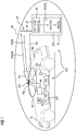
- the arrangement ALO has several components which are arranged on the vehicle side or in or on a vehicle FZ. These include a first vehicle-mounted radio device FE1, which is arranged at a first position PO1 in an outside area AB of the vehicle FZ, here on a roof of the vehicle FZ. This first vehicle-mounted radio device FE1 is set up to transmit one or more radio signals FS1 from position PO1 in the outer area of the vehicle. Furthermore, the arrangement ALO comprises a second vehicle-side radio device FE2, which is arranged at a second position PO2 in an interior area IB of the vehicle, here the passenger compartment.
- the second radio device FE2 on the vehicle is for transmitting an or set up several second radio signals from the position PO2 in the interior of the vehicle.
- the vehicle-side radio device FE2 can be arranged on the roof lining of the vehicle FZ.
- the two radio devices on the vehicle are in close proximity to one another, as in FIG Figure 1 only separated by the body in the roof area of the vehicle in order to be able to deliver reliable results in the localization, in particular the interior / exterior area distinction.
- the radio devices in the vehicle can have antennas that are designed to transmit high-frequency signals, in particular in a Bluetooth frequency band at 2.4 GHz.
- the two vehicle radio devices FE1 and FE2 are connected to a vehicle radio module FM, which is designed to control or drive the two vehicle radio devices so that they transmit their radio signals FS1 and FS2.
- the radio module FM is set up to receive radio signals, such as, for example, a radio signal FA, which is transmitted by a portable radio unit TF to be explained in more detail later.
- the radio signal FA can then either be received via the first vehicle-mounted radio device FE1 or the second vehicle-mounted radio device FE2 and forwarded to the radio module FM.
- the radio signal FA can also be a high-frequency signal, in particular in a Bluetooth frequency band at 2.4 GHz.
- the radio module FM is also connected to a vehicle-side control device STZ, which is designed to evaluate the information contained in the radio signal FA.
- a portable radio unit TF In addition to these vehicle-side components of the arrangement ALO, it also includes a portable radio unit TF.
- This has a radio unit-side receiving device EF for receiving the first and second radio signals FS1 and FS2, as well as for measuring the received field strength R1 of the first radio signal FS1 and for measuring the received field strength R2 of the second radio signal FS2 at the location OF of the portable radio unit TF.
- the radio unit side Receiving device EF is connected to a radio unit-side control device STF, which packs the two received values R1 and R2 of the measured received field strengths into the radio signal FA and transmits them via a radio-unit-side transmitter SF and the radio-unit-side antenna AF or sends them back to the vehicle.
- the vehicle-side control device STZ compares the two values R1 and R2 of the respective measured received field strengths of the radio signals FS1 and FS2.
- the portable radio unit TF is in the outer area AB of the vehicle, since the radio signal FS2 could reach the radio-unit-side antenna AF without hindrance , in contrast to the second radio signal FS2 of the second vehicle-mounted radio device FE2, which initially spread unhindered in the interior IB of the vehicle (shown by the roughly thicker dashed line), and then has a lower field strength attenuated by the vehicle body KA (shown by the Continuing thinner line with arrow regarding the signal FS2).
- the value R2 of the measured received field strength at the location OF of the portable radio unit TF will be lower than the measured field strength R1 of the first radio signal FS1.
- the arrow of the radio signal FS1 is also shown here somewhat thicker than the arrow of the radio signal FS2 after damping by the vehicle body.
- the vehicle-side control device STZ can trigger the corresponding vehicle functions. From the localization in the outer area AB of the vehicle FZ it can be concluded that a driver or user (not shown) has access to the TF by authenticating with his portable radio unit would like to acquire the vehicle, so that the vehicle-side control device STZ outputs a corresponding signal to a door control device TSG, so that this causes a door lock TS to be unlocked.
- the portable radio unit TF is in the interior IB of the vehicle FZ, d. H. localized in the passenger compartment, the value R2 of the measured reception field strength of the second radio signal FS2 being greater than the value R1 of the measured reception field strength of the first radio signal FS1, it is to be expected that a driver carrying the portable radio unit TF would like to start the drive motor of the vehicle so that in this case an immobilizer WF is released by a corresponding signal.
- the portable radio unit TF can be, for example, a conventional radio key, but also a personal portable object that can be carried by a user or driver, such as a smartphone, a smart watch, smart glasses, each equipped with a corresponding radio interface or a corresponding radio unit-side receiving device EF and a radio unit-side transmitting device SF for exchanging said radio signals with the vehicle FZ.
- the vehicle FZ or the radio module FM transmits radio signals AN via the first and / or second vehicle-mounted radio device FE1 or FE2 at regular time intervals. If the portable radio unit TF approaches the vehicle in such a way that it comes into the detection range of the vehicle, that is to say in particular that a first radio signal FS1 is sent from the portable Radio unit TF can be received, the in Figure 2 the sequence shown. It is therefore believed that, as shown in Figure 1 is shown, the portable radio unit TF is located within the detection range of the vehicle FZ, this can also be done here with the in Figure 1 shown outside area AB are equated for illustration purposes.
- a radio signal referred to in this case as a request signal AN
- a request signal AN is sent from the first vehicle-mounted radio device FE1 from the first vehicle-mounted radio device FE1 to the portable radio unit TF.
- the portable radio unit TF or its components are woken up by this request signal AN, with the radio unit-side control device STF being prompted to enter a code CO stored in a memory SP by receiving the request signal AN via the radio-unit-side antenna AF and the radio-unit-side receiving device EF Pack response signal AW.
- the control device STF on the radio unit side causes the transmission device SF on the radio unit side to send the response signal with the code CO via the antenna AF on the radio unit side in step S2 to the vehicle. If the transmitted code CO corresponds to a predetermined code stored in the vehicle or in the vehicle-side control device STZ, the authentication of the portable radio unit TF to the vehicle FZ was positive and the process is continued with the localization of the portable radio unit.
- the localization of the portable radio unit TF now begins with the transmission of a first radio signal FS1 by the first vehicle-mounted radio device FE1 in step S3.
- the received field strength is measured at the location OF of the portable radio unit TF and a corresponding value R1 is determined.
- the second radio signal FS2 is transmitted with a time offset from the transmission of the first radio signal FS1 by the second radio device FE2 in the vehicle.
- the received field strength is measured at the location OF of the portable radio device TF and a corresponding value R2 determined in step S6.
- the radio unit-side control device STF then generates a radio signal FA as a response signal, in which the two values R1 and R2 are contained. It is also conceivable, instead of the values themselves, to pack a difference value between R1 and R2, for example a value R1-R2, into the signal FA and to send it back to the vehicle in a step S8.
- the values R1 and R2 transmitted by the portable radio unit TF are compared with one another.
- the control device STZ in the vehicle checks, for example, whether the value R1 is greater than the value R2. If this is the case, it can be concluded that the portable radio unit TF is located outside the vehicle, since the first radio signal FS1 that the portable radio unit TF could reach, in contrast to the second radio signal FS2, was not attenuated by the body.
- the vehicle-side control device STZ will send a corresponding signal to the door control device TSG so that it unlocks a door lock TS, for example, in order to allow the user of the portable unit TF access to the vehicle.
- step S9 If the comparison of step S9 reveals that the value R2 is greater than the value R1, for example because the user of the portable radio device TF is now sitting in the vehicle with it and the first radio signal is attenuated by the vehicle body in the interior IB interpreted as a sign that the driver or user would like to drive the vehicle and would like to start his drive motor accordingly.
- An immobilizer WF is then released accordingly in a step S11.
- the first on the vehicle side is advantageously used for reliable localization of the portable radio unit TF or for a reliable interior / exterior differentiation Radio device FE1 and the second vehicle-mounted radio device FE2 arranged in the immediate vicinity. Furthermore, the transmission field strength of the first radio signal FS1 and of the second radio signal FS2 are in the same decimal order of magnitude, and in particular are of the same size. By using two radio signals, one from the inside and the other from the outside, and by comparing the two reception field strengths at the location of a portable radio unit, it is possible to use high-frequency radio signals.
Description
Die vorliegende Erfindung betrifft ein Verfahren zur Lokalisierung einer tragbaren Funkeinheit innerhalb eines vorbestimmten Bereichs eines Fahrzeugs. Ferner betrifft sie eine Anordnung zum Lokalisieren der tragbaren Funkeinheit.The present invention relates to a method for localizing a portable radio unit within a predetermined area of a vehicle. It also relates to an arrangement for locating the portable radio unit.
In heutigen Fahrzeugen gehören Startsysteme bzw. Wegfahrsperren als Teil von Diebstahlschutzeinrichtung zur Standardausrüstung. Dabei wird mittels einer Funkkommunikation eine Authentifizierung durchgeführt, bei der an eine tragbare Funkeinheit (insbesondere einen Identifikationsgeber eines Benutzers), die sich im Innenraum des Fahrzeugs befindet, ein Anfragesignal gesendet wird, woraufhin die tragbare Funkeinheit einen Code zurück an eine fahrzeugseitige Auswerteeinrichtung sendet. Diese wird die Wegfahrsperre freigeben und eine Motorstartfreigabe erteilen, wenn der von der tragbaren Funkeinheit übertragene Code gleich einem Sollcode ist.Starting systems or immobilizers are standard equipment in today's vehicles as part of anti-theft systems. An authentication is carried out by means of radio communication, in which a request signal is sent to a portable radio unit (in particular a user's identification transmitter) located in the interior of the vehicle, whereupon the portable radio unit sends a code back to an evaluation device on the vehicle. This will release the immobilizer and issue an engine start release if the code transmitted by the portable radio unit is equal to a reference code.
Neben derartigen gerade beschriebenen Startsystemen für Fahrzeuge gibt es auch Zugangssysteme, um einen unbefugten Zutritt zu einem Fahrzeug zu verhindern. Bei sogenannten passiven Zugangssystemen oder Zugangsanordnungen werden zunächst von einer ersten Kommunikationseinrichtung des Fahrzeugs in regelmäßigen Zeitabständen Anfragesignale einer bestimmten Stärke ausgesendet, um zu überprüfen, ob sich eine tragbare Funkeinheit (ein mobiler Identifikationsgeber eines Benutzers) in einem vorbestimmten Bereich bzw. Erfassungsbereich des Fahrzeugs oder um das Fahrzeug befindet. Nähert sich die tragbare Funkeinheit dem Fahrzeug und kann schließlich dessen Anfragesignale empfangen, so wird sie auf den Empfang eines Anfragesignals antworten, um einen Authentifizierungsvorgang einzuleiten. Dabei werden Daten ausgetauscht, in denen letztendlich die tragbare Funkeinheit seinen Authentifizierungscode dem Fahrzeug übermittelt. Bei erfolgreichem Überprüfen des Authentifizierungscodes ist es dann möglich, dass ein Benutzer, der sich direkt am Fahrzeug befindet, durch Betätigen eines Türgriffs ein Entriegeln der entsprechenden Fahrzeugtür oder aller Fahrzeugtüren erzielt. Da hier kein aktives Betätigen eines mechanischen oder elektrischen Identifikationsgebers bzw. Schlüssels durch einen Benutzer vorgenommen werden muss, wird diese Art der Zugangsberechtigung auch als passive Zugangsberechtigungsprüfung und die entsprechenden Zugangsberechtigungssysteme als passive elektronische Zugangsberechtigungssysteme (kurz: passive Zugangsanordnungen) bezeichnet.In addition to the just described starting systems for vehicles, there are also access systems to prevent unauthorized access to a vehicle. In the case of so-called passive access systems or access arrangements, a first communication device of the vehicle first sends out request signals of a certain strength at regular time intervals in order to check whether a portable radio unit (a mobile identification transmitter of a user) is in or around a predetermined area or detection area of the vehicle the vehicle is located. If the portable radio unit approaches the vehicle and can finally receive its request signals, it will respond to the receipt of a request signal in order to initiate an authentication process. In the process, data is exchanged in which the portable radio unit ultimately transmits its authentication code to the vehicle. When the authentication code is checked successfully it is then possible for a user who is directly at the vehicle to unlock the corresponding vehicle door or all vehicle doors by operating a door handle. Since a user does not have to actively actuate a mechanical or electrical identification transmitter or key, this type of access authorization is also known as a passive access authorization check and the corresponding access authorization systems as passive electronic access authorization systems (in short: passive access arrangements).
Wie gerade erwähnt, kann eine tragbare Funkeinheit bzw. ein mobiler Identifikationsgeber eines Benutzers sowohl für eine Motorstartfreigabe als auch im Rahmen einer passiven Zugangsanordnung beteiligt sein. Dabei soll jedoch eine Motorstartfreigabe jedoch nur bei einer im Innenbereich befindlichen tragbaren Funkeinheit ermöglicht werden, während eine Türentriegelung im Rahmen einer Zugangsanordnung nur bei einer im Außenbereich befindlichen tragbaren Funkeinheit ermöglicht werden soll.As just mentioned, a portable radio unit or a mobile identification transmitter of a user can be involved both for an engine start release and as part of a passive access arrangement. In this case, however, an engine start release should only be enabled for a portable radio unit located in the interior, while door unlocking in the context of an access arrangement should only be enabled for a portable radio unit located in the outdoor area.
Die Druckschrift
Die Druckschrift
Es ist daher die Aufgabe der vorliegenden Erfindung eine einfache Möglichkeit zu schaffen, eine tragbare Funkeinheit in einem vorbestimmten Bereich eines Fahrzeugs zu lokalisieren.It is therefore the object of the present invention to provide a simple way of locating a portable radio unit in a predetermined area of a vehicle.
Diese Aufgabe wird durch die Gegenstände der unabhängigen Ansprüche gelöst. Vorteilhafte Ausgestaltungen sind Gegenstand der Unteransprüche.This object is achieved by the subjects of the independent claims. Advantageous configurations are the subject of the subclaims.
Gemäß einem ersten Aspekt der Erfindung wird ein Verfahren zum Lokalisieren einer tragbaren Funkeinheit eines Benutzers innerhalb eines vorbestimmten Bereichs bzw. Erfassungsbereichs eines Fahrzeugs mit folgenden Schritten geschaffen:
Zunächst wird ein erstes Funksignal von einer fahrzeugseitigen Position im Außenbereich des Fahrzeugs ausgesendet, dies kann durch eine erste fahrzeugseitige Funkeinrichtung im Außenbereich des Fahrzeugs geschehen. Des Weiteren wird ein zweites Funksignal von einer fahrzeugseitigen Position im Innenbereich des Fahrzeugs ausgesendet. Dies kann durch eine zweite fahrzeugseitige Funkeinrichtung im Innenbereich des Fahrzeugs geschehen. Schließlich werden Werte von einer jeweiligen gemessenen Empfangsfeldstärke des ersten und des zweiten Funksignals am Ort der tragbaren Funkeinheit empfangen. Dies kann durch eine fahrzeugseitige Empfangseinrichtung geschehen. Es ist auch denkbar, anstelle der Werte der jeweiligen gemessenen Empfangsfeldstärken des ersten und des zweiten Funksignals am Ort der tragbaren Funkeinheit einen oder mehrere daraus abgeleitete Werte zu empfangen. Beispielsweise ist es denkbar, einen Differenzwert der jeweiligen Werte der gemessenen Empfangsfeldstärke zu empfangen. Des Weiteren wird der Ort der tragbaren Funkeinheit anhand eines Vergleichs der Werte der jeweiligen gemessenen Empfangsfeldstärken ermittelt. Dies kann durch eine fahrzeugseitige Auswerteeinrichtung geschehen. Durch die Verwendung von zwei Funksignalen, eines aus dem Außenbereich und eines aus dem Innenbereich wird sichergestellt, dass egal, wo sich die tragbare Funkeinheit befindet (im Außenbereich oder im Innenbereich), eines der Funksignale eine höhere Feldstärke am Ort der tragbaren Funkeinheit aufweist und das andere eine niedrigere Feldstärke. Dies ist bedingt durch eine Dämpfung der Feldstärke eines Funksignals durch die Fahrzeugkarosserie, die den Außenbereich und den Innenbereich voneinander trennt. Befindet sich beispielsweise die tragbare Funkeinheit im Innenbereich des Fahrzeugs (in der Fahrgastzell), so wird die Dämpfung der Feldstärke des zweiten Funksignals geringer sein als die Dämpfung der Feldstärke des ersten Funksignals. Beim Vergleich der beiden Funksignale, und insbesondere in Kenntnis welches Funksignal aus dem Innenbereich des Fahrzeugs ausgesendet wurde und welches aus dem Außenbereich des Fahrzeugs ausgesendet wurde, kann darauf geschlossen werden, dass im gerade erwähnten Beispiel sich die tragbare Funkeinheit im Innenbereich des Fahrzeugs befindet, da dessen durch die tragbare Funkeinheit gemessene Feldstärke größer als die gemessene Feldstärke des Funksignals aus dem Außenbereich ist. Somit wird eine einfache Möglichkeit der Lokalisierung der tragbaren Funkeinheit ermöglicht.According to a first aspect of the invention, a method for localizing a portable radio unit of a user within a predetermined area or coverage area of a vehicle is provided with the following steps:
First, a first radio signal is transmitted from a vehicle-side position in the outer area of the vehicle; this can be done by a first vehicle-side radio device in the outer area of the vehicle. There is also a second radio signal emitted from a vehicle-side position in the interior of the vehicle. This can be done by a second radio device on the vehicle in the interior of the vehicle. Finally, values of a respective measured received field strength of the first and second radio signals are received at the location of the portable radio unit. This can be done by a receiving device on the vehicle. It is also conceivable to receive one or more values derived therefrom instead of the values of the respective measured reception field strengths of the first and second radio signals at the location of the portable radio unit. For example, it is conceivable to receive a difference value between the respective values of the measured reception field strength. Furthermore, the location of the portable radio unit is determined based on a comparison of the values of the respective measured reception field strengths. This can be done by an evaluation device on the vehicle. The use of two radio signals, one from the outside area and one from the inside area, ensures that no matter where the portable radio unit is located (outside or inside), one of the radio signals has a higher field strength at the location of the portable radio unit and that others have a lower field strength. This is due to the attenuation of the field strength of a radio signal by the vehicle body, which separates the outside area and the inside area. If, for example, the portable radio unit is located inside the vehicle (in the passenger compartment), the attenuation of the field strength of the second radio signal will be less than the attenuation of the field strength of the first radio signal. When comparing the two radio signals, and in particular with knowledge of which radio signal was transmitted from the interior of the vehicle and which was transmitted from the exterior of the vehicle, it can be concluded that in the example just mentioned the portable radio unit is located in the interior of the vehicle, since whose field strength measured by the portable radio unit is greater than the measured field strength of the radio signal from the outside area. This enables a simple way of localizing the portable radio unit.
Gemäß einer Ausgestaltung des Verfahrens liegen die jeweiligen Sendefeldstärken des ersten und des zweiten Funksignals in dergleichen dezimalen Größenordnung. Insbesondere sind sie identisch. Auf diese Weise ist gewährleistet, dass eine entsprechende Dämpfung durch die Fahrzeugkarosserie von einem der beiden Funksignale um einen ausreichenden Betrag gegeben ist, um eine zuverlässige Unterscheidung bzw. einen Vergleich der Werte der jeweiligen gemessenen Empfangsfeldstärken und somit eine zuverlässige Lokalisierung der tragbaren Funkeinheit zu ermöglichen.According to one embodiment of the method, the respective transmission field strengths of the first and second radio signals are in the same decimal order of magnitude. In particular, they are identical. In this way it is ensured that a corresponding attenuation by the vehicle body of one of the two radio signals is provided by a sufficient amount to enable a reliable differentiation or comparison of the values of the respective measured received field strengths and thus a reliable localization of the portable radio unit.
Gemäß einer weiteren Ausgestaltung befindet sich die fahrzeugseitige Position im Außenbereich des Fahrzeugs in der Nähe der fahrzeugseitigen Position im Bereich des Fahrzeugs. Insbesondere ist es möglich, dass sich die beiden Positionen im Dachbereich der Fahrzeugkarosserie befinden, wobei sie dort durch die Karosserie voneinander getrennt sind. Es ist auch möglich, dass sich die beiden Positionen in bzw. an der Fahrzeugtür befinden, wobei sie dort wieder durch das Karosseriematerial, genauer gesagt durch das Blech der Tür, voneinander getrennt sind. So ist es denkbar, dass beispielsweise das erste Funksignal von einer Außenantenne als erste fahrzeugseitige Funkeinrichtung (im Dachbereich, Türbereich, etc.) ausgesendet wird, während das zweite Funksignal von einer Innenantenne als zweite fahrzeugseitige Funkeinrichtung gesendet wird, wobei die beiden Antennen lediglich durch die jeweiligen Teil der Karosserie voneinander getrennt sind, jedoch ansonsten vorteilhafterweise einander gegenüberliegen. Auf diese Weise wird weiter eine gute Unterscheidungsmöglichkeit bezüglich der Empfangsfeldstärke des ersten und des zweiten Funksignals geschaffen, da dadurch sichergestellt wird, dass eine Dämpfung des einen Funksignals gegenüber dem anderen Funksignal erreicht wird.According to a further embodiment, the vehicle-side position is in the outer area of the vehicle in the vicinity of the vehicle-side position in the area of the vehicle. In particular, it is possible for the two positions to be located in the roof area of the vehicle body, where they are separated from one another by the body. It is also possible that the two positions are in or on the vehicle door, where they are again separated from one another by the body material, more precisely by the sheet metal of the door. It is conceivable, for example, that the first radio signal is transmitted from an external antenna as the first radio device on the vehicle (in the roof area, door area, etc.), while the second radio signal is sent from an internal antenna as the second radio device on the vehicle, with the two antennas only through the respective part of the body are separated from one another, but otherwise advantageously opposite one another. In this way, a good way of distinguishing between the received field strength of the first and second radio signals is also created, since this ensures that one radio signal is attenuated in relation to the other radio signal.
Gemäß einer weiteren Ausgestaltung wird ein Ort der tragbaren Funkeinheit im Außenbereich des Fahrzeugs ermittelt, wenn der Vergleich der jeweiligen gemessenen Empfangsfeldstärke ergibt, dass der Wert der gemessenen Empfangsfeldstärke des ersten Funksignals größer als der Wert der gemessenen Empfangsfeldstärke des zweiten Funksignals ist. Entsprechend kann der Ort der tragbaren Funkeinheit im Innenbereich des Fahrzeugs ermittelt werden, wenn der Vergleich der Werte der jeweiligen gemessenen Empfangsfeldstärken ergibt, dass der Wert der gemessenen Empfangsfeldstärke des zweiten Funksignals größer ist, als der Wert der gemessenen Empfangsfeldstärke des ersten Funksignals ist. Auf diese Weise wird eine einfache Möglichkeit der Innenbereichs-/Außenbereichsunterscheidung geschaffen.According to a further embodiment, a location of the portable radio unit in the outside area of the vehicle is determined if the comparison of the respective measured reception field strength shows that the value of the measured reception field strength of the first Radio signal is greater than the value of the measured received field strength of the second radio signal. The location of the portable radio unit in the interior of the vehicle can accordingly be determined if the comparison of the values of the respective measured reception field strengths shows that the value of the measured reception field strength of the second radio signal is greater than the value of the measured reception field strength of the first radio signal. In this way, a simple possibility of differentiating between indoor and outdoor areas is created.
Erfindungsgemäss handelt es sich bei dem ersten und dem zweiten Funksignal um ein Hochfrequenzsignal. Es kann sich dabei um ein Signal im MHz-Bereich, wie beispielsweise im Bereich von 433 MHz handeln, jedoch auch um ein Signal im GHz-Bereich, wie beispielsweise in einem Bluetooth-Frequenzband (auch Bluetooth low energy-Frequenzband) im Bereich von 2,4 GHz oder 5 GHz. Insbesondere bei einer Verwendung einer gemäß dem Bluetooth-Standard benutzten Frequenz ist es denkbar, dass die tragbare Funkeinheit als ein von einem Benutzer mitführbares Gerät, wie beispielsweise ein Smartphone (intelligentes Telefon), eine Smartcard (intelligente Karte), eine Smartwatch (intelligente Uhr) oder als ein entsprechender Funkschlüssel ausgebildet ist, das auf einer entsprechenden Bluetooth-Frequenz kommunizieren kann.According to the invention, the first and the second radio signal are high-frequency signals. It can be a signal in the MHz range, for example in the 433 MHz range, but also a signal in the GHz range, for example in a Bluetooth frequency band (also Bluetooth low energy frequency band) in the range of 2 , 4 GHz or 5 GHz. In particular when using a frequency used in accordance with the Bluetooth standard, it is conceivable that the portable radio unit can be used as a device that can be carried by a user, such as a smartphone (intelligent telephone), a smart card (intelligent card), a smart watch (intelligent watch) or is designed as a corresponding radio key that can communicate on a corresponding Bluetooth frequency.
Gemäß einem weiteren Aspekt der Erfindung wird eine Anordnung zum Lokalisieren einer tragbaren Funkeinheit innerhalb eines vorbestimmten Bereiches bzw. Erfassungsbereichs eines Fahrzeugs geschaffen, die folgende Merkmale umfasst. Sie hat eine erste fahrzeugseitige Funkeinrichtung zum Aussenden eines ersten Funksignals von einer Position im Außenbereich des Fahrzeugs. Ferner hat sie eine zweite fahrzeugseitige Funkeinrichtung zum Aussenden eines zweiten Funksignals von einer Position im Innenbereich des Fahrzeugs. Überdies hat sie eine fahrzeugseitige Empfangseinrichtung zum Empfangen von Werten der jeweiligen gemessenen Empfangsfeldstärken des ersten und des zweiten Funksignals am Ort der tragbaren Funkeinheit oder von einem oder mehreren daraus abgeleiteten Werten. Überdies hat sie eine Auswerteeinrichtung zum Ermitteln des Orts der tragbaren Funkeinheit anhand eines Vergleichs der Werte der jeweiligen gemessenen Empfangsfeldstärken. Somit wird eine Anordnung zum Lokalisieren einer tragbaren Funkeinheit geschaffen, die auf einfache Weise realisierbar ist und auch für hochfrequente Funksignale ausgelegt ist, da hier gezielt eine Abschirmung von Funksignalen auch durch Reflexionen an der Fahrzeugkarosserie dazu genutzt wird, durch Vergleich der Empfangsfeldstärken eines Funksignals aus dem Außenbereich und eines Funksignals aus dem Innenbereich die Ortsbestimmung vorzunehmen.According to a further aspect of the invention, an arrangement for localizing a portable radio unit within a predetermined area or coverage area of a vehicle is provided, which comprises the following features. It has a first vehicle-mounted radio device for transmitting a first radio signal from a position outside the vehicle. It also has a second vehicle-mounted radio device for transmitting a second radio signal from a position in the interior of the vehicle. In addition, it has a vehicle-side receiving device for receiving values of the respective measured received field strengths of the first and second radio signals at the location of the portable radio unit or of one or more values derived therefrom. Besides, she has an evaluation device for determining the location of the portable radio unit based on a comparison of the values of the respective measured reception field strengths. Thus, an arrangement for locating a portable radio unit is created, which can be implemented in a simple manner and is also designed for high-frequency radio signals, since a shielding of radio signals is used here, also by reflections on the vehicle body, by comparing the received field strengths of a radio signal from the Outside area and a radio signal from inside to determine the location.
Gemäß einer Ausgestaltung der Anordnung weist diese ferner eine tragbare Funkeinheit mit folgenden Merkmalen auf. Eine tragbare Funkeinheit hat dabei eine funkeinheitsseitige Empfangseinrichtung zum Empfangen des ersten und des zweiten Funksignals, sowie zum Messen der Empfangsfeldstärke des ersten und des zweiten Funksignals am Ort der tragbaren Funkeinheit. Ferner hat sie eine funkeinheitsseitige Sendeeinrichtung zum Aussenden der jeweiligen gemessenen Empfangsfeldstärken des ersten und des zweiten Funksignals. Es ist auch denkbar, dass die funkeinheitsseitige Sendeeinrichtung einen aus den jeweiligen gemessenen Empfangsfeldstärken des ersten und des zweiten Funksignals abgeleiteten Wert oder abgeleitete Werte aussendet. Beispielsweise kann eine Differenz der Empfangsfeldstärken des ersten und des zweiten Funksignals ausgesendet werden.According to one embodiment of the arrangement, it also has a portable radio unit with the following features. A portable radio unit has a radio unit-side receiving device for receiving the first and the second radio signal, as well as for measuring the received field strength of the first and the second radio signal at the location of the portable radio unit. It also has a transmitting device on the radio unit side for transmitting the respective measured received field strengths of the first and second radio signals. It is also conceivable that the transmission device on the radio unit side transmits a value or values derived from the respective measured reception field strengths of the first and second radio signals. For example, a difference in the received field strengths of the first and second radio signals can be transmitted.
Gemäß einem weiteren Aspekt der Erfindung wird ein Fahrzeug mit einer obigen Anordnung oder einer Ausgestaltung hiervon geschaffen.According to a further aspect of the invention, a vehicle having the above arrangement or an embodiment thereof is provided.
Gemäße einer Ausgestaltung des Fahrzeugs weist dieses einen Außenbereich sowie einen Innenbereich auf. Außerdem hat es eine Karosserie, die den Außenbereich vom Innenbereich trennt, wobei die ersten fahrzeugseitige Funkeinrichtung an der Außenseite der Karosserie und die zweite fahrzeugseitige Funkeinrichtung an der Innenseite der Karosserie, insbesondere jeweils im Dachbereich oder im Türbereich angeordnet sind. Auf diese Weise wird eine gute Unterscheidungsmöglichkeit der Empfangsfeldstärke des Funksignals von der ersten fahrzeugseitigen Funkeinrichtung an der Außenseite der Karosserie und des Funksignals von der zweiten fahrzeugseitigen Funkeinrichtung an der Innenseite der Karosserie ermöglicht.According to one embodiment of the vehicle, it has an outside area and an inside area. It also has a body that separates the outside from the inside, the first vehicle-side radio device being arranged on the outside of the body and the second vehicle-side radio device being arranged on the inside of the body, in particular in the roof area or in the door area. This provides a good way of differentiating the received field strength of the radio signal from the first vehicle-side radio device on the outside of the body and the radio signal from the second vehicle-side radio device on the inside of the body.
Vorteilhafte Ausgestaltungen des Verfahrens sind, soweit auf die Anordnungen des Fahrzeugs anwendbar auch als vorteilhafte Ausgestaltungen der Anordnungen des Fahrzeugs zu sehen, und umgekehrt.To the extent that they are applicable to the arrangements of the vehicle, advantageous refinements of the method are also to be seen as advantageous refinements of the arrangements of the vehicle, and vice versa.
Im Folgenden sollen nun beispielhafte Ausführungsformen der vorliegenden Erfindung bezugnehmend auf die beiliegenden Zeichnungen erläutert werden. Es zeigen:
- Figur 1
- eine schematische Darstellung einer Anordnung zum Lokalisieren einer tragbaren Funkeinheit im Erfassungsbereich eines Fahrzeugs gemäß einer Ausführungsform der Erfindung;
- Figur 2
- ein Ablaufdiagramm zum Darstellen des Verfahrens zum Lokalisieren einer tragbaren Einheit gemäß einer Ausführungsform der Erfindung.
- Figure 1
- a schematic representation of an arrangement for locating a portable radio unit in the detection range of a vehicle according to an embodiment of the invention;
- Figure 2
- a flowchart for illustrating the method for locating a portable unit according to an embodiment of the invention.
Es sei nun auf
Die fahrzeugseitigen Funkeinrichtungen können dabei Antennen aufweisen, die dafür ausgelegt sind, Hochfrequenzsignale auszusenden, insbesondere in einem Bluetooth-Frequenzband bei 2,4 GHz. Die beiden fahrzeugseitigen Funkeinrichtungen FE1 und FE2 sind mit einem fahrzeugseitigen Funkmodul FM verbunden, das dafür ausgelegt ist, die beiden fahrzeugseitigen Funkeinrichtungen anzusteuern bzw. zu treiben, damit diese ihre Funksignale FS1 bzw. FS2 aussenden. Desweiteren ist das Funkmodul FM dazu eingerichtet, Funksignale zu empfangen, wie beispielsweise ein Funksignal FA, das von einer später näher zu erläuternden tragbaren Funkeinheit TF ausgesendet wird. Das Funksignal FA kann dann entweder über die erste fahrzeugseitige Funkeinrichtung FE1 oder die zweite fahrzeugseitige Funkeinrichtung FE2 empfangen und zum Funkmodul FM weitergeleitet werden. Bei dem Funksignal FA kann es sich auch um ein Hochfrequenzsignal handeln, insbesondere in einem Bluetooth-Frequenzband bei 2, 4 GHz. Das Funkmodul FM ist desweiterein mit einer fahrzeugseitigen Steuereinrichtung STZ verbunden, die zum Auswerten der in dem Funksignal FA enthaltenen Informationen ausgelegt ist.The radio devices in the vehicle can have antennas that are designed to transmit high-frequency signals, in particular in a Bluetooth frequency band at 2.4 GHz. The two vehicle radio devices FE1 and FE2 are connected to a vehicle radio module FM, which is designed to control or drive the two vehicle radio devices so that they transmit their radio signals FS1 and FS2. Furthermore, the radio module FM is set up to receive radio signals, such as, for example, a radio signal FA, which is transmitted by a portable radio unit TF to be explained in more detail later. The radio signal FA can then either be received via the first vehicle-mounted radio device FE1 or the second vehicle-mounted radio device FE2 and forwarded to the radio module FM. The radio signal FA can also be a high-frequency signal, in particular in a Bluetooth frequency band at 2.4 GHz. The radio module FM is also connected to a vehicle-side control device STZ, which is designed to evaluate the information contained in the radio signal FA.
Neben diesen fahrzeugseitigen Komponenten der Anordnung ALO umfasst diese ferner eine tragbare Funkeinheit TF. Diese hat eine funkeinheitsseitige Empfangseinrichtung EF zum Empfangen des ersten und des zweiten Funksignals FS1 und FS2, sowie zum Messen der Empfangsfeldstärke R1 des ersten Funksignals FS1 und zum Messen der Empfangsfeldstärke R2 des zweiten Funksignals FS2 am Ort OF der tragbaren Funkeinheit TF. Die funkeinheitsseitige Empfangseinrichtung EF ist mit einer funkeinheitsseitigen Steuereinrichtung STF verbunden, die die beiden erhaltenen Werte R1 und R2 der gemessenen Empfangsfeldstärken in das Funksignal FA packt und über eine funkeinheitsseitige Sendeeinrichtung SF und die funkeinheitsseitige Antenne AF aussendet bzw. zum Fahrzeug zurücksendet.In addition to these vehicle-side components of the arrangement ALO, it also includes a portable radio unit TF. This has a radio unit-side receiving device EF for receiving the first and second radio signals FS1 and FS2, as well as for measuring the received field strength R1 of the first radio signal FS1 and for measuring the received field strength R2 of the second radio signal FS2 at the location OF of the portable radio unit TF. The radio unit side Receiving device EF is connected to a radio unit-side control device STF, which packs the two received values R1 and R2 of the measured received field strengths into the radio signal FA and transmits them via a radio-unit-side transmitter SF and the radio-unit-side antenna AF or sends them back to the vehicle.
Es sei noch einmal verwiesen auf die fahrzeugseitige Steuereinrichtung STZ, deren Aufgabe es ist, den Ort OF der tragbaren Funkeinheit TF zu ermitteln. Dabei vergleicht die fahrzeugseitige Steuereinrichtung STZ die beiden Werte R1 und R2 der jeweiligen gemessenen Empfangsfeldstärken der Funksignale FS1 und FS2. Ist der Wert R1 der Empfangsfeldstärke des ersten Funksignals größer als der Wert R2 der gemessenen Empfangsfeldstärke des zweiten Funksignals FS2, so bedeutet dies, dass sich die tragbare Funkeinheit TF im Außenbereich AB des Fahrzeugs befindet, da das Funksignal FS2 ungehindert zur funkeinheitsseitigen Antenne AF gelangen konnte, im Gegensatz zum zweiten Funksignal FS2 der zweiten fahrzeugseitigen Funkeinrichtung FE2, das sich zunächst ungehindert im Innenbereich IB des Fahrzeugs ausgebreitet hat (dargestellt durch die etwa dicker dargestellte gestrichelte Linie), und dann durch die Fahrzeugkarosserie KA gedämpft eine geringere Feldstärke aufweist (dargestellt durch die weiterführende dünnere Linie mit Pfeil bzgl. des Signals FS2). Entsprechend wird der Wert R2 der gemessenen Empfangsfeldstärke am Ort OF der tragbaren Funkeinheit TF geringer sein als die gemessene Feldstärke R1 des ersten Funksignals FS1. Entsprechend ist auch der Pfeil des Funksignals FS1 hier etwas dicker dargestellt, als der Pfeil des Funksignals FS2 nach Dämpfung durch die Fahrzeugkarosserie.Reference should once again be made to the control device STZ in the vehicle, the task of which is to determine the location OF of the portable radio unit TF. The vehicle-side control device STZ compares the two values R1 and R2 of the respective measured received field strengths of the radio signals FS1 and FS2. If the value R1 of the received field strength of the first radio signal is greater than the value R2 of the measured received field strength of the second radio signal FS2, this means that the portable radio unit TF is in the outer area AB of the vehicle, since the radio signal FS2 could reach the radio-unit-side antenna AF without hindrance , in contrast to the second radio signal FS2 of the second vehicle-mounted radio device FE2, which initially spread unhindered in the interior IB of the vehicle (shown by the roughly thicker dashed line), and then has a lower field strength attenuated by the vehicle body KA (shown by the Continuing thinner line with arrow regarding the signal FS2). Correspondingly, the value R2 of the measured received field strength at the location OF of the portable radio unit TF will be lower than the measured field strength R1 of the first radio signal FS1. Correspondingly, the arrow of the radio signal FS1 is also shown here somewhat thicker than the arrow of the radio signal FS2 after damping by the vehicle body.
Wurde wie oben gerade erläutert, festgestellt, dass sich der Ort OF der tragbaren Funkeinheit TF im Außenbereich des Fahrzeugs befindet, so kann die fahrzeugseitige Steuereinrichtung STZ die entsprechenden Fahrzeugfunktionen auslösen. Aus der Lokalisierung im Außenbereich AB des Fahrzeugs FZ kann geschlossen werden, dass ein Fahrer oder Benutzer (nicht dargestellt) durch Authentifizieren mit seiner tragbaren Funkeinheit TF Zugang zum Fahrzeug erlangen möchte, sodass bei der Lokalisierung im Außenbereich die fahrzeugseitige Steuereinrichtung STZ an ein Türsteuergerät TSG ein entsprechendes Signal ausgibt, damit dieses ein Entriegeln eines Türschlosses TS veranlasst.If, as just explained above, it was determined that the location OF of the portable radio unit TF is in the outside area of the vehicle, then the vehicle-side control device STZ can trigger the corresponding vehicle functions. From the localization in the outer area AB of the vehicle FZ it can be concluded that a driver or user (not shown) has access to the TF by authenticating with his portable radio unit Would like to acquire the vehicle, so that the vehicle-side control device STZ outputs a corresponding signal to a door control device TSG, so that this causes a door lock TS to be unlocked.
Wird die tragbare Funkeinheit TF hingegen im Innenbereich IB des Fahrzeugs FZ, d. h. in der Fahrgastzelle lokalisiert, wobei der Wert R2 der gemessenen Empfangsfeldstärke des zweiten Funksignals FS2 größer als der Wert R1 der gemessenen Empfangsfeldstärke des ersten Funksignals FS1 ist, so ist damit zu rechnen, dass ein die tragbare Funkeinheit TF mitführender Fahrer den Antriebsmotor des Fahrzeugs starten möchte, sodass in diesem Fall eine Wegfahrsperre WF durch ein entsprechendes Signal gelöst wird.If the portable radio unit TF, however, is in the interior IB of the vehicle FZ, d. H. localized in the passenger compartment, the value R2 of the measured reception field strength of the second radio signal FS2 being greater than the value R1 of the measured reception field strength of the first radio signal FS1, it is to be expected that a driver carrying the portable radio unit TF would like to start the drive motor of the vehicle so that in this case an immobilizer WF is released by a corresponding signal.
Bei der tragbaren Funkeinheit TF kann es sich hierbei beispielsweise um einen herkömmlichen Funkschlüssel, jedoch auch um einen persönlichen von einem Benutzer bzw. Fahrer mitführbaren tragbaren Gegenstand handeln, wie ein Smartphone, eine Smartwatch, smart glasses (eine intelligente Brille), jeweils ausgestattet mit einer entsprechenden Funkschnittstelle bzw. einer entsprechenden funkeinheitsseitigen Empfangseinrichtung EF und einer funkeinheitsseitigen Sendeeinrichtung SF zum Austauschen der genannten Funksignale mit dem Fahrzeug FZ.The portable radio unit TF can be, for example, a conventional radio key, but also a personal portable object that can be carried by a user or driver, such as a smartphone, a smart watch, smart glasses, each equipped with a corresponding radio interface or a corresponding radio unit-side receiving device EF and a radio unit-side transmitting device SF for exchanging said radio signals with the vehicle FZ.
Es sei nun auf
Dabei wird davon ausgegangen, dass sich ein Fahrer bzw. Benutzer (nicht dargestellt) mit seiner tragbaren Funkeinheit TF dem Fahrzeug FZ nähert. Das Fahrzeug FZ bzw. das Funkmodul FM sendet über die erste und/oder zweite fahrzeugseitige Funkeinrichtung FE1 bzw. FE2 in regelmäßigen Zeitabständen Funksignale AN aus. Nähert sich die tragbare Funkeinheit TF derart dem Fahrzeug, dass sie in den Erfassungsbereich des Fahrzeugs kommt, d. h. dass insbesondere ein erstes Funksignal FS1 von der tragbaren Funkeinheit TF empfangen werden kann, so soll nun der in
In einem Schritt S1 wird dabei von der ersten fahrzeugseitigen Funkeinrichtung FE1 ein Funksignal, in diesem Fall als ein Anfragesignal AN bezeichnet, von der ersten fahrzeugseitigen Funkeinrichtung FE1 zur tragbaren Funkeinheit TF gesendet. Durch dieses Anfragesignal AN wird die tragbare Funkeinheit TF bzw. deren Komponenten aufgeweckt, wobei durch den Empfang des Anfragesignals AN über die funkeinheitsseitige Antenne AF und die funkeinheitsseitige Empfangseinrichtung EF die funkeinheitsseitige Steuereinrichtung STF dazu veranlasst wird, einen in einem Speicher SP gespeicherten Code CO in ein Antwortsignal AW zu packen. Entsprechend veranlasst die funkeinheitsseitige Steuereinrichtung STF die funkeinheitsseitige Sendeeinrichtung SF das Antwortsignal mit dem Code CO über die funkeinheitsseitige Antenne AF in Schritt S2 zum Fahrzeug zu senden. Entspricht der übertragene Code CO einem im Fahrzeug bzw. in der fahrzeugseitigen Steuereinrichtung STZ gespeicherten vorbestimmten Code, so ist die Authentifizierung der tragbaren Funkeinheit TF gegenüber dem Fahrzeug FZ positiv verlaufen und der Ablauf wird mit der Lokalisierung der tragbaren Funkeinheit fortgesetzt.In a step S1, a radio signal, referred to in this case as a request signal AN, is sent from the first vehicle-mounted radio device FE1 from the first vehicle-mounted radio device FE1 to the portable radio unit TF. The portable radio unit TF or its components are woken up by this request signal AN, with the radio unit-side control device STF being prompted to enter a code CO stored in a memory SP by receiving the request signal AN via the radio-unit-side antenna AF and the radio-unit-side receiving device EF Pack response signal AW. Correspondingly, the control device STF on the radio unit side causes the transmission device SF on the radio unit side to send the response signal with the code CO via the antenna AF on the radio unit side in step S2 to the vehicle. If the transmitted code CO corresponds to a predetermined code stored in the vehicle or in the vehicle-side control device STZ, the authentication of the portable radio unit TF to the vehicle FZ was positive and the process is continued with the localization of the portable radio unit.
Wie es bereits bezüglich
Nach diesem ersten Teil der Lokalisierung, bei dem Funksignale zwischen dem Fahrzeug FZ und der tragbaren Funkeinheit TF ausgetauscht worden sind, beginnt nun die Auswertung. In einem Schritt S9 werden dabei die von der tragbaren Funkeinheit TF übermittelten Werte R1 und R2 miteinander verglichen. Dabei prüft die fahrzeugseitige Steuereinrichtung STZ beispielsweise, ob der Wert R1 größer als der Wert R2 ist. Ist dies der Fall, so kann darauf geschlossen werden, dass sich die tragbare Funkeinheit TF im Außenbereich des Fahrzeugs befindet, da das erste Funksignal FS1, das die tragbare Funkeinheit TF erreichen konnte im Gegensatz zum zweiten Funksignal FS2 nicht durch die Karosserie gedämpft worden ist. Entsprechend wird die fahrzeugseitige Steuereinrichtung STZ an das Türsteuergerät TSG ein entsprechendes Signal aussenden, damit dieses beispielsweise ein Türschloss TS entriegelt, um den Benutzer der tragbaren Einheit TF Zugang zum Fahrzeug zu gewähren.After this first part of the localization, in which radio signals have been exchanged between the vehicle FZ and the portable radio unit TF, the evaluation now begins. In a step S9, the values R1 and R2 transmitted by the portable radio unit TF are compared with one another. The control device STZ in the vehicle checks, for example, whether the value R1 is greater than the value R2. If this is the case, it can be concluded that the portable radio unit TF is located outside the vehicle, since the first radio signal FS1 that the portable radio unit TF could reach, in contrast to the second radio signal FS2, was not attenuated by the body. Correspondingly, the vehicle-side control device STZ will send a corresponding signal to the door control device TSG so that it unlocks a door lock TS, for example, in order to allow the user of the portable unit TF access to the vehicle.
Kommt beim Vergleich von Schritt S9 heraus, dass der Wert R2 größer als der Wert R1 ist, beispielsweise weil der Benutzer der tragbaren Funkeinrichtung TF mit dieser mittlerweile im Fahrzeug sitzt, und im Innenbereich IB das erste Funksignal durch die Fahrzeugkarosserie gedämpft wird, so wird dies als Zeichen gedeutet, dass der Fahrer bzw. Benutzer mit dem Fahrzeug fahren möchte und entsprechend seinen Antriebsmotor starten möchte. Entsprechend wird dann in einem Schritt S11 eine Wegfahrsperre WF freigegeben.If the comparison of step S9 reveals that the value R2 is greater than the value R1, for example because the user of the portable radio device TF is now sitting in the vehicle with it and the first radio signal is attenuated by the vehicle body in the interior IB interpreted as a sign that the driver or user would like to drive the vehicle and would like to start his drive motor accordingly. An immobilizer WF is then released accordingly in a step S11.
Vorteilhafterweise wird für eine zuverlässige Lokalisierung der tragbaren Funkeinheit TF bzw. für eine zuverlässige Innenbereich-/ Außenbereichsunterscheidung die erste fahrzeugseitige Funkeinrichtung FE1 und die zweite fahrzeugseitige Funkeinrichtung FE2 in unmittelbarer Nähe angeordnet. Desweiteren liegen die Sendefeldstärke des ersten Funksignals FS1 und des zweiten Funksignals FS2 in der gleichen dezimalen Größenordnung, und sind insbesondere gleichgroß. Durch die Verwendung von zwei Funksignalen, eines aus dem Innenbereich und das andere aus dem Außenbereich und durch den Vergleich der beiden Empfangsfeldstärken am Ort einer tragbaren Funkeinheit ist es somit möglich, hochfrequente Funksignale verwenden zu können.The first on the vehicle side is advantageously used for reliable localization of the portable radio unit TF or for a reliable interior / exterior differentiation Radio device FE1 and the second vehicle-mounted radio device FE2 arranged in the immediate vicinity. Furthermore, the transmission field strength of the first radio signal FS1 and of the second radio signal FS2 are in the same decimal order of magnitude, and in particular are of the same size. By using two radio signals, one from the inside and the other from the outside, and by comparing the two reception field strengths at the location of a portable radio unit, it is possible to use high-frequency radio signals.
Claims (10)
- Method for locating a portable radio unit (TF) within a predetermined area of a vehicle (FZ), having the following steps:transmitting (S3) a first radio signal (FS1) as a radio-frequency signal from a vehicle-based position (PO1) outside the vehicle (FZ);transmitting (S5) a second radio signal (FS2) as a radio-frequency signal from a vehicle-based position (PO2) inside the vehicle;receiving (S8) values (R1, R2) of the respective measured reception field strengths of the first and second radio signals (FS1, FS2) at the location (OF) of the portable radio unit or a value derived therefrom;ascertaining (S9) the location (OF) of the portable radio unit (TF) on the basis of a comparison of the values (R1, R2) of the respective measured reception field strengths.
- Method according to Claim 1, in which the respective transmission field strength of the first and second radio signals (FS1, FS2) are in the same decimal order of magnitude, and in particular are identical.
- Method according to Claim 1 or 2, in which the vehicle-based position (PO1) outside the vehicle is close to the vehicle-based position (PO2) inside the vehicle (FZ).
- Method according to one of Claims 1 to 3, in which a location (OF) of the portable radio unit (TF) outside the vehicle is ascertained if the comparison of the values of the respective measured reception field strengths reveals that the value (R1) of the measured reception field strength of the first radio signal (FS1) is greater than the value (R2) of the measured reception field strength of the second radio signal (FS2).
- Method according to one of Claims 1 to 4, in which a location (OF) of the portable radio unit (TF) inside (IB) the vehicle is ascertained if the comparison of the values of the respective measured reception field strength reveals that the value (R2) of the measured reception field strength of the second radio signal (FS2) is greater than the value (R1) of the measured reception field strength of the first radio signal (FS1).
- Arrangement (ALO) for locating a portable radio unit (TF) within a predetermined area of a vehicle (FZ), having the following features:a first vehicle-based radio device (FE1) for transmitting a first radio signal as a radio-frequency signal from a position (PO1) outside (AB) the vehicle (FZ);a second vehicle-based radio device (FE2) for transmitting a second radio signal (FS2) as a radio-frequency signal from a position (PO2) inside (IB) the vehicle (FZ);a vehicle-based reception device (FE1, FE2; FM) for receiving values (R1, R2) of the respective measured reception field strengths of the first and second radio signals (FS1, FS2) at the location (OF) of the portable radio unit (TF);an evaluation device (STZ) for ascertaining the location (OF) of the portable radio unit (TF) on the basis of a comparison of the values (R1, R2) of the respective measured reception field strengths.
- Arrangement according to Claim 6, which further has a portable radio unit having the following features:a radio-unit-based reception device (EF) for receiving the first and second radio signals (FS1, FS2), and for measuring the reception field strength of the first and second radio signals (FS1, FS2) at the location of the portable radio unit (TF);a radio-unit-based transmission device (SF) for transmitting the values (R1, R2) of the respective measured reception field strengths of the first and second radio signals (FS1, FS2) or a value derived therefrom.
- Vehicle (FZ) having an arrangement (ALO) according to either of Claims 6 and 7.
- Vehicle according to Claim 8, which has:an outside (AB);an inside (IB);a bodywork that separates the outside (AB) from the inside (IB), wherein the first vehicle-based radio device (FE1) is arranged on the outside of the bodywork (KA) and the second vehicle-based radio device (FE2) is arranged on the inside of the bodywork.
- Vehicle according to Claim 9,
in which the first vehicle-based radio device (FE1) and the second vehicle-based radio device (FE2) are arranged in the roof area in each case.
Applications Claiming Priority (2)
| Application Number | Priority Date | Filing Date | Title |
|---|---|---|---|
| DE102015217413.1A DE102015217413B4 (en) | 2015-09-11 | 2015-09-11 | Method and device for locating a portable radio unit |
| PCT/EP2016/069947 WO2017042030A1 (en) | 2015-09-11 | 2016-08-24 | Method and arrangement for localizing a portable radio unit |
Publications (2)
| Publication Number | Publication Date |
|---|---|
| EP3347246A1 EP3347246A1 (en) | 2018-07-18 |
| EP3347246B1 true EP3347246B1 (en) | 2020-11-18 |
Family
ID=56853594
Family Applications (1)
| Application Number | Title | Priority Date | Filing Date |
|---|---|---|---|
| EP16760009.7A Active EP3347246B1 (en) | 2015-09-11 | 2016-08-24 | Method and arrangement for localizing a portable radio unit |
Country Status (5)
| Country | Link |
|---|---|
| US (1) | US11460533B2 (en) |
| EP (1) | EP3347246B1 (en) |
| JP (1) | JP2018534540A (en) |
| DE (1) | DE102015217413B4 (en) |
| WO (1) | WO2017042030A1 (en) |
Families Citing this family (5)
| Publication number | Priority date | Publication date | Assignee | Title |
|---|---|---|---|---|
| DE102017217978A1 (en) * | 2017-10-10 | 2019-04-11 | Continental Automotive Gmbh | Access system and access verification method |
| JP6927060B2 (en) * | 2018-01-19 | 2021-08-25 | トヨタ自動車株式会社 | In-vehicle communication device and communication method |
| DE102018209258A1 (en) * | 2018-06-11 | 2019-12-12 | Bayerische Motoren Werke Aktiengesellschaft | METHOD AND ARRANGEMENT FOR DETERMINING A STORAGE RANGE OF A RADIO DEVICE, AND VEHICLE WITH SUCH AN ARRANGEMENT |
| SE544177C2 (en) * | 2019-10-08 | 2022-02-22 | Assa Abloy Ab | Inside or outside a barrier comprising an rf barrier |
| FR3113738B1 (en) * | 2020-09-01 | 2022-07-29 | Continental Automotive | Method for activating a function of a vehicle by ultra wide band with portable user equipment, system and device for activating an associated function |
Citations (2)
| Publication number | Priority date | Publication date | Assignee | Title |
|---|---|---|---|---|
| US6906612B2 (en) * | 2002-04-11 | 2005-06-14 | Lear Corporation | System and method for vehicle passive entry having inside/outside detection |
| DE102013227204A1 (en) * | 2012-12-28 | 2014-07-03 | Trw Automotive Italia S.R.L. | IMPROVED SYSTEM FOR PASSIVE ACCESS AND PASSIVE START FOR A MOTOR VEHICLE |
Family Cites Families (29)
| Publication number | Priority date | Publication date | Assignee | Title |
|---|---|---|---|---|
| DE19738323C1 (en) | 1997-09-02 | 1999-02-04 | Siemens Ag | Locating transponder based remote control unit used for car central locking system |
| DE19809433C1 (en) * | 1998-03-05 | 1999-06-24 | Siemens Ag | Initialisation method for motor vehicle anti-theft protection system |
| DE19836957C1 (en) * | 1998-08-14 | 1999-09-30 | Siemens Ag | Theft protection arrangement for motor vehicle |
| US6774764B2 (en) * | 2000-02-25 | 2004-08-10 | Delphi Technologies, Inc. | Securing system for motor vehicle |
| EP1189306B1 (en) * | 2000-09-19 | 2004-12-01 | Land Rover | A security system |
| DE50101902D1 (en) * | 2001-01-30 | 2004-05-13 | Siemens Ag | Method for operating an access control system, in particular for a motor vehicle, and access control system |
| DE10131102B4 (en) * | 2001-06-27 | 2017-06-08 | Witte-Velbert Gmbh & Co. Kg | With a key and exterior door handle equipped locking device for a motor vehicle door |
| JP2005072972A (en) * | 2003-08-25 | 2005-03-17 | Alps Electric Co Ltd | Passive keyless entry system |
| DE102004059179B4 (en) * | 2004-12-08 | 2006-12-28 | Siemens Ag | Method for locating a transmitting and receiving device |
| US7446644B2 (en) * | 2005-01-14 | 2008-11-04 | Secureall Corporation | Universal hands free key and lock system |
| DE602005001935T2 (en) * | 2005-05-11 | 2008-05-08 | Delphi Technologies, Inc., Troy | Hands-free control system for vehicles |
| JP4723415B2 (en) | 2005-11-24 | 2011-07-13 | 株式会社東海理化電機製作所 | Electronic key system |
| JP4493640B2 (en) * | 2006-11-07 | 2010-06-30 | アルプス電気株式会社 | Keyless entry device |
| US7850078B2 (en) * | 2007-04-23 | 2010-12-14 | Lear Corporation | Remote control reactivation |
| JP2009027249A (en) * | 2007-07-17 | 2009-02-05 | Nissan Motor Co Ltd | Radio communication system for vehicle |
| US8315617B2 (en) * | 2009-10-31 | 2012-11-20 | Btpatent Llc | Controlling mobile device functions |
| US8508419B2 (en) * | 2010-10-22 | 2013-08-13 | GM Global Technology Operations LLC | Multiple antenna element system and method |
| JP5604314B2 (en) * | 2011-01-13 | 2014-10-08 | オムロンオートモーティブエレクトロニクス株式会社 | Detection device, detection system, and detection method for radio wave handset |
| JP5449231B2 (en) * | 2011-02-18 | 2014-03-19 | 三菱電機株式会社 | Vehicle radio equipment |
| DE102011088917B4 (en) * | 2011-12-16 | 2013-12-24 | Continental Automotive Gmbh | Access arrangement in the method for operating such an access arrangement |
| US9472035B2 (en) * | 2012-02-23 | 2016-10-18 | Trw Automotive U.S. Llc | Remote convenience method and apparatus with reduced signal nulls |
| DE102012216843B3 (en) * | 2012-09-20 | 2014-03-13 | Continental Automotive Gmbh | Access arrangement for vehicle, has vehicle-mounted transceiver for temporal successive transmission of interrogation signals in predetermined time intervals, and mobile identification sensor with identification sensor-sided transceiver |
| US9921290B2 (en) * | 2012-11-08 | 2018-03-20 | Intrepid Networks, Llc | System and method for situational awareness |
| US9337914B2 (en) * | 2012-11-27 | 2016-05-10 | Blackberry Limited | System and method for communicating with a portable electronic device |
| AU2013202164B2 (en) * | 2013-03-28 | 2016-05-12 | Robert Bosch (Australia) Pty Ltd | Method for determining the location of a remote transmitter positioned near a vehicle |
| JP2015072162A (en) * | 2013-10-02 | 2015-04-16 | パナソニックIpマネジメント株式会社 | Short-range wireless communication system for vehicle |
| EP3077254B1 (en) * | 2013-12-03 | 2019-09-25 | Huf North America Automotive Parts Mfg. Corp. | Vehicle control system to prevent relay attack |
| JP6528368B2 (en) * | 2014-07-14 | 2019-06-12 | 株式会社オートネットワーク技術研究所 | Communication system for vehicle, in-vehicle device, portable device, and computer program |
| US9418491B2 (en) * | 2014-09-22 | 2016-08-16 | Brian K. Phillips | Method and system for automatically identifying a driver by creating a unique driver profile for a vehicle from driving habits |
-
2015
- 2015-09-11 DE DE102015217413.1A patent/DE102015217413B4/en active Active
-
2016
- 2016-08-24 US US15/758,667 patent/US11460533B2/en active Active
- 2016-08-24 EP EP16760009.7A patent/EP3347246B1/en active Active
- 2016-08-24 JP JP2018512940A patent/JP2018534540A/en active Pending
- 2016-08-24 WO PCT/EP2016/069947 patent/WO2017042030A1/en active Application Filing
Patent Citations (2)
| Publication number | Priority date | Publication date | Assignee | Title |
|---|---|---|---|---|
| US6906612B2 (en) * | 2002-04-11 | 2005-06-14 | Lear Corporation | System and method for vehicle passive entry having inside/outside detection |
| DE102013227204A1 (en) * | 2012-12-28 | 2014-07-03 | Trw Automotive Italia S.R.L. | IMPROVED SYSTEM FOR PASSIVE ACCESS AND PASSIVE START FOR A MOTOR VEHICLE |
Also Published As
| Publication number | Publication date |
|---|---|
| DE102015217413A1 (en) | 2017-03-16 |
| US20180252794A1 (en) | 2018-09-06 |
| US11460533B2 (en) | 2022-10-04 |
| EP3347246A1 (en) | 2018-07-18 |
| JP2018534540A (en) | 2018-11-22 |
| WO2017042030A1 (en) | 2017-03-16 |
| DE102015217413B4 (en) | 2017-09-28 |
Similar Documents
| Publication | Publication Date | Title |
|---|---|---|
| EP3347246B1 (en) | Method and arrangement for localizing a portable radio unit | |
| EP3236427B1 (en) | Method and system for passive access control | |
| DE10202330B4 (en) | Locking system, in particular for a motor vehicle | |
| DE102014101086A1 (en) | Mobile device for a keyless entry or actuation system for motor vehicles | |
| WO2000043622A1 (en) | Keyless access control device for motor vehicles and method for carrying out a keyless access authorization control in motor vehicles | |
| DE102016111276A1 (en) | Method for controlling access to a motor vehicle | |
| WO2004057542A1 (en) | Vehicle security system | |
| DE202013103554U1 (en) | Device for dual-range detection in a vehicle | |
| DE102005017458A1 (en) | Operating lock system, especially for motor vehicle, involves comparing field strength of each component of range demarcation signal with first and second thresholds, determining area of location using especially Boolean combinations | |
| DE102008015477A1 (en) | Closing system, particularly for access or driving authorization for vehicle in style of keyless entry or go function, has device, with two positions, formed as control device | |
| EP1867535B1 (en) | Locking system, in particular for a motor vehicle | |
| DE10160964B4 (en) | Method and device for theft protection of motor vehicles | |
| DE19836973B4 (en) | Access and start / drive authorization system for a vehicle | |
| DE102004036920B4 (en) | Locking system, in particular for a motor vehicle | |
| DE10149344A1 (en) | Authorization interrogation device for motor vehicles sets control unit in vehicle inoperative using noise signal so only unit outside vehicle is evaluated for authorization for locking/unlocking | |
| EP1191487A2 (en) | Locking system, in particular for a vehicle | |
| EP2825424B1 (en) | Locking system, especially for a motor vehicle | |
| DE102020207244A1 (en) | Access arrangement for a vehicle | |
| DE102007004063A1 (en) | Mobile identification transmitter of a security system | |
| DE102014018668A1 (en) | Locking system, in particular for a motor vehicle | |
| DE102020207098B3 (en) | Access system and procedure for access and launch verification | |
| EP1588909B1 (en) | Locking system, in particular for a vehicle | |
| EP3310627B1 (en) | Locking system for a vehicle | |
| DE102005030082A1 (en) | Method for data transmission in particular in key-less car door opening system, comprising specific signal for transfer from resting into activated stage | |
| DE102006030642A1 (en) | identification system |
Legal Events
| Date | Code | Title | Description |
|---|---|---|---|
| STAA | Information on the status of an ep patent application or granted ep patent |
Free format text: STATUS: THE INTERNATIONAL PUBLICATION HAS BEEN MADE |
|
| PUAI | Public reference made under article 153(3) epc to a published international application that has entered the european phase |
Free format text: ORIGINAL CODE: 0009012 |
|
| STAA | Information on the status of an ep patent application or granted ep patent |
Free format text: STATUS: REQUEST FOR EXAMINATION WAS MADE |
|
| 17P | Request for examination filed |
Effective date: 20180411 |
|
| AK | Designated contracting states |
Kind code of ref document: A1 Designated state(s): AL AT BE BG CH CY CZ DE DK EE ES FI FR GB GR HR HU IE IS IT LI LT LU LV MC MK MT NL NO PL PT RO RS SE SI SK SM TR |
|
| AX | Request for extension of the european patent |
Extension state: BA ME |
|
| DAV | Request for validation of the european patent (deleted) | ||
| DAX | Request for extension of the european patent (deleted) | ||
| GRAP | Despatch of communication of intention to grant a patent |
Free format text: ORIGINAL CODE: EPIDOSNIGR1 |
|
| STAA | Information on the status of an ep patent application or granted ep patent |
Free format text: STATUS: GRANT OF PATENT IS INTENDED |
|
| INTG | Intention to grant announced |
Effective date: 20200706 |
|
| RAP1 | Party data changed (applicant data changed or rights of an application transferred) |
Owner name: CONTINENTAL AUTOMOTIVE GMBH |
|
| GRAS | Grant fee paid |
Free format text: ORIGINAL CODE: EPIDOSNIGR3 |
|
| GRAA | (expected) grant |
Free format text: ORIGINAL CODE: 0009210 |
|
| STAA | Information on the status of an ep patent application or granted ep patent |
Free format text: STATUS: THE PATENT HAS BEEN GRANTED |
|
| AK | Designated contracting states |
Kind code of ref document: B1 Designated state(s): AL AT BE BG CH CY CZ DE DK EE ES FI FR GB GR HR HU IE IS IT LI LT LU LV MC MK MT NL NO PL PT RO RS SE SI SK SM TR |
|
| REG | Reference to a national code |
Ref country code: GB Ref legal event code: FG4D Free format text: NOT ENGLISH |
|
| REG | Reference to a national code |
Ref country code: CH Ref legal event code: EP |
|
| REG | Reference to a national code |
Ref country code: IE Ref legal event code: FG4D Free format text: LANGUAGE OF EP DOCUMENT: GERMAN |
|
| REG | Reference to a national code |
Ref country code: DE Ref legal event code: R096 Ref document number: 502016011751 Country of ref document: DE |
|
| REG | Reference to a national code |
Ref country code: AT Ref legal event code: REF Ref document number: 1335431 Country of ref document: AT Kind code of ref document: T Effective date: 20201215 |
|
| REG | Reference to a national code |
Ref country code: NL Ref legal event code: MP Effective date: 20201118 |
|
| PG25 | Lapsed in a contracting state [announced via postgrant information from national office to epo] |
Ref country code: GR Free format text: LAPSE BECAUSE OF FAILURE TO SUBMIT A TRANSLATION OF THE DESCRIPTION OR TO PAY THE FEE WITHIN THE PRESCRIBED TIME-LIMIT Effective date: 20210219 Ref country code: FI Free format text: LAPSE BECAUSE OF FAILURE TO SUBMIT A TRANSLATION OF THE DESCRIPTION OR TO PAY THE FEE WITHIN THE PRESCRIBED TIME-LIMIT Effective date: 20201118 Ref country code: RS Free format text: LAPSE BECAUSE OF FAILURE TO SUBMIT A TRANSLATION OF THE DESCRIPTION OR TO PAY THE FEE WITHIN THE PRESCRIBED TIME-LIMIT Effective date: 20201118 Ref country code: PT Free format text: LAPSE BECAUSE OF FAILURE TO SUBMIT A TRANSLATION OF THE DESCRIPTION OR TO PAY THE FEE WITHIN THE PRESCRIBED TIME-LIMIT Effective date: 20210318 Ref country code: NO Free format text: LAPSE BECAUSE OF FAILURE TO SUBMIT A TRANSLATION OF THE DESCRIPTION OR TO PAY THE FEE WITHIN THE PRESCRIBED TIME-LIMIT Effective date: 20210218 |
|
| PG25 | Lapsed in a contracting state [announced via postgrant information from national office to epo] |
Ref country code: SE Free format text: LAPSE BECAUSE OF FAILURE TO SUBMIT A TRANSLATION OF THE DESCRIPTION OR TO PAY THE FEE WITHIN THE PRESCRIBED TIME-LIMIT Effective date: 20201118 Ref country code: BG Free format text: LAPSE BECAUSE OF FAILURE TO SUBMIT A TRANSLATION OF THE DESCRIPTION OR TO PAY THE FEE WITHIN THE PRESCRIBED TIME-LIMIT Effective date: 20210218 Ref country code: LV Free format text: LAPSE BECAUSE OF FAILURE TO SUBMIT A TRANSLATION OF THE DESCRIPTION OR TO PAY THE FEE WITHIN THE PRESCRIBED TIME-LIMIT Effective date: 20201118 Ref country code: PL Free format text: LAPSE BECAUSE OF FAILURE TO SUBMIT A TRANSLATION OF THE DESCRIPTION OR TO PAY THE FEE WITHIN THE PRESCRIBED TIME-LIMIT Effective date: 20201118 Ref country code: IS Free format text: LAPSE BECAUSE OF FAILURE TO SUBMIT A TRANSLATION OF THE DESCRIPTION OR TO PAY THE FEE WITHIN THE PRESCRIBED TIME-LIMIT Effective date: 20210318 |
|
| REG | Reference to a national code |
Ref country code: LT Ref legal event code: MG9D |
|
| PG25 | Lapsed in a contracting state [announced via postgrant information from national office to epo] |
Ref country code: HR Free format text: LAPSE BECAUSE OF FAILURE TO SUBMIT A TRANSLATION OF THE DESCRIPTION OR TO PAY THE FEE WITHIN THE PRESCRIBED TIME-LIMIT Effective date: 20201118 |
|
| PG25 | Lapsed in a contracting state [announced via postgrant information from national office to epo] |
Ref country code: EE Free format text: LAPSE BECAUSE OF FAILURE TO SUBMIT A TRANSLATION OF THE DESCRIPTION OR TO PAY THE FEE WITHIN THE PRESCRIBED TIME-LIMIT Effective date: 20201118 Ref country code: CZ Free format text: LAPSE BECAUSE OF FAILURE TO SUBMIT A TRANSLATION OF THE DESCRIPTION OR TO PAY THE FEE WITHIN THE PRESCRIBED TIME-LIMIT Effective date: 20201118 Ref country code: SM Free format text: LAPSE BECAUSE OF FAILURE TO SUBMIT A TRANSLATION OF THE DESCRIPTION OR TO PAY THE FEE WITHIN THE PRESCRIBED TIME-LIMIT Effective date: 20201118 Ref country code: LT Free format text: LAPSE BECAUSE OF FAILURE TO SUBMIT A TRANSLATION OF THE DESCRIPTION OR TO PAY THE FEE WITHIN THE PRESCRIBED TIME-LIMIT Effective date: 20201118 Ref country code: SK Free format text: LAPSE BECAUSE OF FAILURE TO SUBMIT A TRANSLATION OF THE DESCRIPTION OR TO PAY THE FEE WITHIN THE PRESCRIBED TIME-LIMIT Effective date: 20201118 Ref country code: RO Free format text: LAPSE BECAUSE OF FAILURE TO SUBMIT A TRANSLATION OF THE DESCRIPTION OR TO PAY THE FEE WITHIN THE PRESCRIBED TIME-LIMIT Effective date: 20201118 |
|
| REG | Reference to a national code |
Ref country code: DE Ref legal event code: R097 Ref document number: 502016011751 Country of ref document: DE |
|
| PG25 | Lapsed in a contracting state [announced via postgrant information from national office to epo] |
Ref country code: DK Free format text: LAPSE BECAUSE OF FAILURE TO SUBMIT A TRANSLATION OF THE DESCRIPTION OR TO PAY THE FEE WITHIN THE PRESCRIBED TIME-LIMIT Effective date: 20201118 |
|
| PLBE | No opposition filed within time limit |
Free format text: ORIGINAL CODE: 0009261 |
|
| STAA | Information on the status of an ep patent application or granted ep patent |
Free format text: STATUS: NO OPPOSITION FILED WITHIN TIME LIMIT |
|
| 26N | No opposition filed |
Effective date: 20210819 |
|
| PG25 | Lapsed in a contracting state [announced via postgrant information from national office to epo] |
Ref country code: NL Free format text: LAPSE BECAUSE OF FAILURE TO SUBMIT A TRANSLATION OF THE DESCRIPTION OR TO PAY THE FEE WITHIN THE PRESCRIBED TIME-LIMIT Effective date: 20201118 Ref country code: IT Free format text: LAPSE BECAUSE OF FAILURE TO SUBMIT A TRANSLATION OF THE DESCRIPTION OR TO PAY THE FEE WITHIN THE PRESCRIBED TIME-LIMIT Effective date: 20201118 Ref country code: AL Free format text: LAPSE BECAUSE OF FAILURE TO SUBMIT A TRANSLATION OF THE DESCRIPTION OR TO PAY THE FEE WITHIN THE PRESCRIBED TIME-LIMIT Effective date: 20201118 |
|
| PG25 | Lapsed in a contracting state [announced via postgrant information from national office to epo] |
Ref country code: SI Free format text: LAPSE BECAUSE OF FAILURE TO SUBMIT A TRANSLATION OF THE DESCRIPTION OR TO PAY THE FEE WITHIN THE PRESCRIBED TIME-LIMIT Effective date: 20201118 |
|
| PG25 | Lapsed in a contracting state [announced via postgrant information from national office to epo] |
Ref country code: ES Free format text: LAPSE BECAUSE OF FAILURE TO SUBMIT A TRANSLATION OF THE DESCRIPTION OR TO PAY THE FEE WITHIN THE PRESCRIBED TIME-LIMIT Effective date: 20201118 |
|
| REG | Reference to a national code |
Ref country code: CH Ref legal event code: PL |
|
| PG25 | Lapsed in a contracting state [announced via postgrant information from national office to epo] |
Ref country code: MC Free format text: LAPSE BECAUSE OF FAILURE TO SUBMIT A TRANSLATION OF THE DESCRIPTION OR TO PAY THE FEE WITHIN THE PRESCRIBED TIME-LIMIT Effective date: 20201118 |
|
| REG | Reference to a national code |
Ref country code: BE Ref legal event code: MM Effective date: 20210831 |
|
| GBPC | Gb: european patent ceased through non-payment of renewal fee |
Effective date: 20210824 |
|
| PG25 | Lapsed in a contracting state [announced via postgrant information from national office to epo] |
Ref country code: LI Free format text: LAPSE BECAUSE OF NON-PAYMENT OF DUE FEES Effective date: 20210831 Ref country code: CH Free format text: LAPSE BECAUSE OF NON-PAYMENT OF DUE FEES Effective date: 20210831 |
|
| PG25 | Lapsed in a contracting state [announced via postgrant information from national office to epo] |
Ref country code: IS Free format text: LAPSE BECAUSE OF FAILURE TO SUBMIT A TRANSLATION OF THE DESCRIPTION OR TO PAY THE FEE WITHIN THE PRESCRIBED TIME-LIMIT Effective date: 20210318 Ref country code: LU Free format text: LAPSE BECAUSE OF NON-PAYMENT OF DUE FEES Effective date: 20210824 |
|
| REG | Reference to a national code |
Ref country code: DE Ref legal event code: R081 Ref document number: 502016011751 Country of ref document: DE Owner name: CONTINENTAL AUTOMOTIVE TECHNOLOGIES GMBH, DE Free format text: FORMER OWNER: CONTINENTAL AUTOMOTIVE GMBH, 30165 HANNOVER, DE |
|
| PG25 | Lapsed in a contracting state [announced via postgrant information from national office to epo] |
Ref country code: IE Free format text: LAPSE BECAUSE OF NON-PAYMENT OF DUE FEES Effective date: 20210824 Ref country code: GB Free format text: LAPSE BECAUSE OF NON-PAYMENT OF DUE FEES Effective date: 20210824 Ref country code: BE Free format text: LAPSE BECAUSE OF NON-PAYMENT OF DUE FEES Effective date: 20210831 |
|
| REG | Reference to a national code |
Ref country code: AT Ref legal event code: MM01 Ref document number: 1335431 Country of ref document: AT Kind code of ref document: T Effective date: 20210824 |
|
| PG25 | Lapsed in a contracting state [announced via postgrant information from national office to epo] |
Ref country code: AT Free format text: LAPSE BECAUSE OF NON-PAYMENT OF DUE FEES Effective date: 20210824 |
|
| PG25 | Lapsed in a contracting state [announced via postgrant information from national office to epo] |
Ref country code: HU Free format text: LAPSE BECAUSE OF FAILURE TO SUBMIT A TRANSLATION OF THE DESCRIPTION OR TO PAY THE FEE WITHIN THE PRESCRIBED TIME-LIMIT; INVALID AB INITIO Effective date: 20160824 |
|
| PG25 | Lapsed in a contracting state [announced via postgrant information from national office to epo] |
Ref country code: CY Free format text: LAPSE BECAUSE OF FAILURE TO SUBMIT A TRANSLATION OF THE DESCRIPTION OR TO PAY THE FEE WITHIN THE PRESCRIBED TIME-LIMIT Effective date: 20201118 |
|
| PGFP | Annual fee paid to national office [announced via postgrant information from national office to epo] |
Ref country code: FR Payment date: 20230825 Year of fee payment: 8 Ref country code: DE Payment date: 20230831 Year of fee payment: 8 |
|
| REG | Reference to a national code |
Ref country code: DE Ref legal event code: R081 Ref document number: 502016011751 Country of ref document: DE Owner name: CONTINENTAL AUTOMOTIVE TECHNOLOGIES GMBH, DE Free format text: FORMER OWNER: CONTINENTAL AUTOMOTIVE TECHNOLOGIES GMBH, 30165 HANNOVER, DE |