EP3346757B1 - System message transmission method and device - Google Patents
System message transmission method and device Download PDFInfo
- Publication number
- EP3346757B1 EP3346757B1 EP16840814.4A EP16840814A EP3346757B1 EP 3346757 B1 EP3346757 B1 EP 3346757B1 EP 16840814 A EP16840814 A EP 16840814A EP 3346757 B1 EP3346757 B1 EP 3346757B1
- Authority
- EP
- European Patent Office
- Prior art keywords
- pbch
- subframe
- slot
- ofdm symbols
- system message
- Prior art date
- Legal status (The legal status is an assumption and is not a legal conclusion. Google has not performed a legal analysis and makes no representation as to the accuracy of the status listed.)
- Active
Links
- 238000000034 method Methods 0.000 title claims description 28
- 230000005540 biological transmission Effects 0.000 title claims description 27
- 230000007774 longterm Effects 0.000 claims description 5
- 238000004891 communication Methods 0.000 claims description 4
- 238000013507 mapping Methods 0.000 description 18
- 238000001228 spectrum Methods 0.000 description 9
- 230000011664 signaling Effects 0.000 description 7
- 238000013461 design Methods 0.000 description 4
- 238000005516 engineering process Methods 0.000 description 4
- 238000010586 diagram Methods 0.000 description 3
- 230000006870 function Effects 0.000 description 3
- 125000004122 cyclic group Chemical group 0.000 description 1
- 230000001419 dependent effect Effects 0.000 description 1
- 238000010295 mobile communication Methods 0.000 description 1
- 238000012986 modification Methods 0.000 description 1
- 230000004048 modification Effects 0.000 description 1
- 230000003287 optical effect Effects 0.000 description 1
Images

Classifications
-
- H—ELECTRICITY
- H04—ELECTRIC COMMUNICATION TECHNIQUE
- H04W—WIRELESS COMMUNICATION NETWORKS
- H04W28/00—Network traffic management; Network resource management
- H04W28/02—Traffic management, e.g. flow control or congestion control
- H04W28/08—Load balancing or load distribution
-
- H—ELECTRICITY
- H04—ELECTRIC COMMUNICATION TECHNIQUE
- H04L—TRANSMISSION OF DIGITAL INFORMATION, e.g. TELEGRAPHIC COMMUNICATION
- H04L5/00—Arrangements affording multiple use of the transmission path
- H04L5/003—Arrangements for allocating sub-channels of the transmission path
- H04L5/0058—Allocation criteria
- H04L5/0073—Allocation arrangements that take into account other cell interferences
-
- H—ELECTRICITY
- H04—ELECTRIC COMMUNICATION TECHNIQUE
- H04W—WIRELESS COMMUNICATION NETWORKS
- H04W72/00—Local resource management
- H04W72/30—Resource management for broadcast services
-
- H—ELECTRICITY
- H04—ELECTRIC COMMUNICATION TECHNIQUE
- H04L—TRANSMISSION OF DIGITAL INFORMATION, e.g. TELEGRAPHIC COMMUNICATION
- H04L5/00—Arrangements affording multiple use of the transmission path
- H04L5/0001—Arrangements for dividing the transmission path
- H04L5/0003—Two-dimensional division
- H04L5/0005—Time-frequency
- H04L5/0007—Time-frequency the frequencies being orthogonal, e.g. OFDM(A), DMT
-
- H—ELECTRICITY
- H04—ELECTRIC COMMUNICATION TECHNIQUE
- H04L—TRANSMISSION OF DIGITAL INFORMATION, e.g. TELEGRAPHIC COMMUNICATION
- H04L5/00—Arrangements affording multiple use of the transmission path
- H04L5/003—Arrangements for allocating sub-channels of the transmission path
- H04L5/0048—Allocation of pilot signals, i.e. of signals known to the receiver
- H04L5/005—Allocation of pilot signals, i.e. of signals known to the receiver of common pilots, i.e. pilots destined for multiple users or terminals
-
- H—ELECTRICITY
- H04—ELECTRIC COMMUNICATION TECHNIQUE
- H04L—TRANSMISSION OF DIGITAL INFORMATION, e.g. TELEGRAPHIC COMMUNICATION
- H04L5/00—Arrangements affording multiple use of the transmission path
- H04L5/003—Arrangements for allocating sub-channels of the transmission path
- H04L5/0053—Allocation of signaling, i.e. of overhead other than pilot signals
-
- H—ELECTRICITY
- H04—ELECTRIC COMMUNICATION TECHNIQUE
- H04W—WIRELESS COMMUNICATION NETWORKS
- H04W48/00—Access restriction; Network selection; Access point selection
- H04W48/08—Access restriction or access information delivery, e.g. discovery data delivery
- H04W48/10—Access restriction or access information delivery, e.g. discovery data delivery using broadcasted information
-
- H—ELECTRICITY
- H04—ELECTRIC COMMUNICATION TECHNIQUE
- H04W—WIRELESS COMMUNICATION NETWORKS
- H04W72/00—Local resource management
- H04W72/50—Allocation or scheduling criteria for wireless resources
- H04W72/52—Allocation or scheduling criteria for wireless resources based on load
-
- H—ELECTRICITY
- H04—ELECTRIC COMMUNICATION TECHNIQUE
- H04W—WIRELESS COMMUNICATION NETWORKS
- H04W72/00—Local resource management
- H04W72/50—Allocation or scheduling criteria for wireless resources
- H04W72/54—Allocation or scheduling criteria for wireless resources based on quality criteria
- H04W72/541—Allocation or scheduling criteria for wireless resources based on quality criteria using the level of interference
-
- H—ELECTRICITY
- H04—ELECTRIC COMMUNICATION TECHNIQUE
- H04J—MULTIPLEX COMMUNICATION
- H04J11/00—Orthogonal multiplex systems, e.g. using WALSH codes
- H04J11/0023—Interference mitigation or co-ordination
- H04J11/0066—Interference mitigation or co-ordination of narrowband interference
Definitions
- the invention relates to the field of wireless communications, and more particularly to a system message transmission method and device.
- MTC Machine Type Communication
- M2M Machine to Machine
- 3GPP 3rd Generation Partnership Project
- TR45.820V200 3rd Generation Partnership Project
- NB-LTE Narrowband Long Term Evolution
- a subcarrier interval of the relevant LTE system is 15kHz.
- the LTE system supports the following six system bandwidths, i.e., 1.4MHz, 3MHz, 5MHz, 10MHz, 15MHz and 20MHz, and these six bandwidths respectively have 72, 150, 300, 600, 900 and 1200 available subcarriers.
- the transmission bandwidth and downlink subcarrier interval of the NB-LTE system are the same as the bandwidth and subcarrier interval of one PRB of the LTE system respectively, the NB-LTE system and the LTE system may coexist in the same spectrum. For example, in the LTE system of which the system bandwidth is 20MHz, a bandwidth of 180kHz may be allocated for sending an NB-LTE system signal.
- Embodiments of the invention provide system message transmission methods for an NB-LTE system according to appended claims 1, 13 and system message transmission devices for an NB-LTE system according to appended claims 7, 16. Further aspects of the invention are provided according to the appended dependent claims.
- a radio frame in an LTE system may follow frame structures in a Frequency Division Duplex (FDD) mode and a Time Division Duplex (TDD) mode.
- the frame structure in the FDD mode is as shown in Fig. 1 .
- a radio frame of 10ms may consist of twenty slots of 0.5ms, numbered as 0 to 19, and slots 2i and 2i+1 may form a subframe i of 1ms.
- CP Cyclic Prefix
- each slot may contain 7 symbols of 66.7us, wherein the CP length of the first symbol is 5.21us, and the CP lengths of the other six symbols are 4.69us.
- each slot may contain 6 symbols, and the CP length of all the symbols are 16.67us.
- the NB-LTE system needs to send a system message to an NB-LTE UE to inform of available resources, in order that the NB-LTE system can perform data transmission according to whether a spectrum is shared. Meanwhile, consistency between the NB-LTE system and the NB-LTE UE is also ensured.
- an embodiment of the invention provides a system message transmission method, including the steps as follows.
- a physical downlink channel may be transmitted according to the system message.
- the system message may include at least one of: frequency domain location information of a system, configuration information of a physical shared channel carrying a system message, configuration information of terminal access, available resource information of the physical downlink channel, and radio frame information.
- the method in the embodiments of the invention is applied to NB-LTE.
- the system message may be transmitted at the preset resource location via a PBCH.
- the first predefined OFDM symbols may include a second OFDM symbol, a third OFDM symbol and last two OFDM symbols of each slot.
- Initial locations of the antenna ports of the narrowband reference signal may be determined according to a cell identity.
- the synchronization channel may be located on a subframe #9, and the PBCH may be located on a subframe #0.
- the one or more subframes may include one or more of a subframe #0 of a radio frame, a subframe #4 of a radio frame, a subframe #5 of a radio frame, or a subframe #9 of a radio frame.
- the PBCH may be transmitted at an interval of Z1 radio frames, and may be repeatedly transmitted for Z2 times by every Z1 *Z2 radio frames.
- Z1 may be equal to 4, 6, 8, 12 or 24, and Z2 may be equal to 4, 6, 8, 12 or 16.
- the physical shared channel carrying the system message may be located on W successive radio frames, W being equal to 3, 6, 9 or 12.
- the system module may be configured to transmit a system message at a preset resource location.
- the channel module may be configured to transmit a physical downlink channel according to the system message.
- the system message may include at least one of: frequency domain location information of a system, configuration information of a physical shared channel carrying a system message, configuration information of terminal access, available resource information of the physical downlink channel, and radio frame information.
- the available resource information of the physical downlink channel may include: information of a start OFDM symbol of the physical downlink channel in a subframe, and/or information of one or more unavailable resource elements of the physical downlink channel in a subframe, and/or information of one or more available subframes of the physical downlink channel.
- the indication via the CRS port location and/or the CSI-RS port location may be determined by a number of ports and/or a virtual cell identity.
- the virtual cell identity is mainly used to indicate a cell identity of an LTE system during coexistence of a new system (narrowband system) and the LTE system, so that the reference signal location can be determined.
- the information of one or more available subframes of the physical downlink channel may be indicated in one of the following alternative manners.
- the available subframes may be periodically indicated by using a bitmap.
- unavailable subframes may be periodically indicated by using a bitmap.
- J bits may be used to indicate the availability of each subframe in J subframes.
- each bit correspondingly indicates the availability of one subframe in J subframes, for example, 1 represents Available, and 0 represents Unavailable; or, 0 represents Available, and 1 represents Unavailable.
- J may be equal to 40, 80, 120, 160 or 240.
- the system module may be configured to transmit a system message at a preset resource location in the following manner.
- the information of one or more available resource elements of the physical downlink channel in a subframe may be indicated via a CRS port location and/or a CSI-RS port location.
- the CRS port location may be 1, 2 or 4, or, the CRS port location may be 1 or 4.
- the system message may be transmitted at a preset resource location in the following manner.
- the system message may be transmitted at a preset resource location via a PBCH.
- the PBCH may be located on any R OFDM symbols in first predefined OFDM symbols in a subframe, wherein R may be equal to 4, 5, 6 or 8.
- the first predefined OFDM symbols may include at least one of: a second OFDM symbol of each slot, a fourth last OFDM symbol of each slot, last two OFDM symbols of each slot, and a third OFDM symbol of each slot.
- the preset resource location may be embodied as follows.
- the PBCH may be mapped to T radio frames, and may be located on the same one or more subframes of each radio frame.
- the one or more subframes may include one or more of a subframe #0 of a radio frame, a subframe #4 of a radio frame, a subframe #5 of a radio frame, or a subframe #9 of a radio frame.
- the system message may be transmitted at a preset resource location via a physical shared channel in the following manner.
- a start OFDM symbol of a physical shared channel carrying the system message in a subframe may be a fixed value, and corresponding available resource elements may be remaining resources after a fixed virtual cell CRS port is removed.
- the physical shared channel carrying the system message, the synchronization channel and the PBCH may be located on different subframes.
- the system message may include at least one of: frequency domain location information of a system, configuration information of a physical shared channel carrying a system message, configuration information of terminal access, available resource information of the physical downlink channel, and radio frame information.
- the available resource information of the physical downlink channel may include: information of a start OFDM symbol of the physical downlink channel in a subframe, and/or information of one or more unavailable resource elements of the physical downlink channel in a subframe, and/or information of one or more available subframes of the physical downlink channel.
- the information of one or more available subframes of the physical downlink channel may be indicated in one of the following alternative manners.
- the available subframes may be indicated periodically by using a bitmap.
- the unavailable subframes may be indicated periodically by using a bitmap.
- J bits may be used to indicate the availability of each subframe in J subframes.
- each bit correspondingly indicates the availability of one subframe in J subframes, for example, 1 represents Available, and 0 represents Unavailable; or, 0 represents Available, and 1 represents Unavailable.
- J may be 40, 80, 120, 160 or 240.
- the information of the one or more unavailable resource elements may be indicated via a CRS port location and/or a CSI-RS port location.
- the indication via the CRS port location and/or the CSI-RS port location may be determined by a number of ports and/or a virtual cell identity.
- the system message may be transmitted at a preset resource location in the following manner.
- the system message may be transmitted at a preset resource location via a PBCH.
- the PBCH may be located on any R OFDM symbols in first predefined OFDM symbols in a subframe, wherein R may be equal to 4, 5, 6 or 8.
- the first predefined OFDM symbols may include at least one of: a second OFDM symbol of each slot, a fourth last OFDM symbol of each slot, last two OFDM symbols of each slot, and a third OFDM symbol of each slot.
- the first predefined OFDM symbols may include last two OFDM symbols of each slot.
- the first predefined OFDM symbols may include last two OFDM symbols of each slot and a fourth last OFDM symbol of a second slot, or, the first predefined OFDM symbols may include last two OFDM symbols of each slot and a third OFDM symbol of a second slot.
- the first predefined OFDM symbols may include a second OFDM symbol, a third OFDM symbol and last two OFDM symbols of each slot.
- the PBCH and a synchronization channel may be located on adjacent subframes.
- the preset resource location may be embodied as follows.
- the PBCH may be mapped to T radio frames, and may be located on the same one or more subframes of each radio frame.
- the one or more subframes may include one or more of a subframe #0 of a radio frame, a subframe #4 of a radio frame, a subframe #5 of a radio frame, or a subframe #9 of a radio frame.
- Z1 may be equal to 4, 6, 8, 12 or 24, and Z2 may be equal to 4, 6, 8, 12 or 16.
- the system message may be transmitted at a preset resource location in one of the following manners.
- the system message may be transmitted at a preset resource location via a physical shared channel.
- the system message may be transmitted at a preset resource location via a physical shared channel and a PBCH.
- the system message may be transmitted at a preset resource location via a physical shared channel in the following manner.
- a start OFDM symbol of a physical shared channel carrying the system message in a subframe may be a fixed value, and corresponding available resource elements may be remaining resources after a fixed virtual cell CRS port is removed.
- the physical shared channel carrying the system message, the synchronization channel and the PBCH may be located on different subframes.
- the system message may include available resource information and radio frame information of the physical downlink channel and may be carried by a PBCH.
- a first mapping mode may include: a physical downlink channel is mapped starting from a first OFDM symbol of a subframe, and corresponding available resource elements may be remaining resources after a fixed single-port virtual cell CRS is removed.
- a second mapping mode may include: a physical downlink channel is mapped starting from a fourth OFDM symbol of a subframe, and corresponding available resource elements may be remaining resources after a fixed four-port virtual cell CRS is removed.
- the PBCH may be mapped to eight successive radio frames, and may be located on a fixed subframe #Y1 of each radio frame.
- Y1 may be equal to one or more of 0, 4, 5 and 9.
- the PBCH may be transmitted for eight times within each period by taking 64 radio frames as a period.
- the PBCH may be mapped to eight successive radio frames, and may be located on a fixed subframe #Y1 of each radio frame.
- Y1 may be equal to one or more of 0, 4, 5 and 9.
- the PBCH may be transmitted for 12 times within each period by taking 96 radio frames as a period.
- the system message may include frequency domain location information of a system, configuration information of a physical shared channel carrying a system message, configuration information of terminal access, and radio frame information.
- the system message may be carried by a PBCH.
- the symbol may include first four or five OFDM symbols of a second slot of a subframe, or, the last OFDM symbol of a first slot of a subframe and first four OFDM symbols of a second slot of the subframe, or, last two OFDM symbols of a first slot of a subframe and first four OFDM symbols of a second slot of the subframe, or, last two OFDM symbols of a first slot of a subframe and first six OFDM symbols of a second slot of the subframe, or, last three OFDM symbols of a first slot of a subframe and first five OFDM symbols of a second slot of the subframe, or, last five OFDM symbols of a first slot of a subframe and first seven OFDM symbols of a second slot of the subframe, or, last three OFDM symbols of a first slot of a subframe and all OFDM symbols of a second slot of the subframe.
- the PBCH may be mapped to six successive radio frames, and may be located on a fixed subframe #Y1 of each radio frame. Y1 may be equal to one or more of 0, 4, 5 and 9.
- the PBCH may be transmitted for four times within each period by taking 24 radio frames as a period.
- the PBCH may be mapped to first three successive radio frames of every six radio frames, and may be located on a fixed subframe #Y1 of each radio frame.
- Y1 may be equal to one or more of 0, 4, 5 and 9.
- the PBCH may be transmitted for four times within each period by taking 24 radio frames as a period.
- the synchronization channel may be located on a subframe #8 of a radio frame, and the PBCH may be located on a subframe #9 of the radio frame.
- the synchronization channel may be located on a subframe #6 of a radio frame, and the PBCH may be located on a subframe #5 of the radio frame.
- the synchronization channel may be located on a subframe #3 of a radio frame, and the PBCH may be located on a subframe #4 of the radio frame.
- the synchronization channel may be located on a subframe #1 of a radio frame, and the PBCH may be located on a subframe #0 of the radio frame.
- the PBCH may be located on last Y OFDM symbols of a first slot of a subframe and first X OFDM symbols of a second slot of the subframe, wherein X may be equal to 4, 5, 6 or 7, and Y may be equal to 0, 1, 2, 3, 4 or 5.
- the symbol may include first four or five OFDM symbols of a second slot of a subframe, or, the last OFDM symbol of a first slot of a subframe and first four OFDM symbols of a second slot of the subframe, or, last two OFDM symbols of a first slot of a subframe and first four OFDM symbols of a second slot of the subframe, or, last two OFDM symbols of a first slot of a subframe and first six OFDM symbols of a second slot of the subframe, or, last three OFDM symbols of a first slot of a subframe and first five OFDM symbols of a second slot of the subframe, or, last five OFDM symbols of a first slot of a subframe and first seven OFDM symbols of a second slot of the subframe, or, last three OFDM symbols of a first slot of a subframe and all OFDM symbols of a second slot of the subframe.
- the available resource information of the physical downlink channel and the configuration information of terminal access may be carried by a PBCH.
- a start OFDM symbol of a physical shared channel carrying the system message in a subframe may be a first OFDM symbol, and corresponding available resource elements may be remaining resources after removing a 4-port virtual cell CRS port.
- the physical downlink shared channel may be transmitted in a single-port manner.
- the information of the start OFDM symbol of the physical downlink channel in a subframe may occupy 1 bit, indicating a first OFDM symbol, or a k th OFDM symbol, where k may be equal to 3, 4 or 5.
- the information of the start OFDM symbol of the physical downlink channel in a subframe may occupy 2 bits, indicating the first, second, third or fourth OFDM symbol.
- the CRS port location may be 1, 2 or 4, or, the CRS port location may be 1 or 4.
- the CSI-RS port location may include Null, or may be one or more selected CSI-RS resource configuration indexes in a relevant LTE system.
- Another embodiment of the invention provides a computer storage medium in which a computer-executable instruction is stored.
- the computer-executable instruction is used to execute the method in the above-mentioned embodiments.
- the above-mentioned technical solutions can reduce the interference between signals during spectrum sharing between different systems and reduce the occurrence of simultaneous transmission of different signals over the same resource by different systems, thereby ensuring consistency between a system and a terminal, and improving the data transmission performance.
Landscapes
- Engineering & Computer Science (AREA)
- Signal Processing (AREA)
- Computer Networks & Wireless Communication (AREA)
- Computer Security & Cryptography (AREA)
- Quality & Reliability (AREA)
- Mobile Radio Communication Systems (AREA)
Description
- The invention relates to the field of wireless communications, and more particularly to a system message transmission method and device.
- A Machine Type Communication (MTC) User Equipment (UE), which is also referred to as a Machine to Machine (M2M) user communication equipment, is a main application form of a current Internet Of Things (IOT). In a 3rd Generation Partnership Project (3GPP) technical report TR45.820V200, several technologies applicable to a Cell-IOT (C-IOT) are proposed. Among all the technologies, a Narrowband Long Term Evolution (NB-LTE) technology is the most attention-grabbing technology. The system bandwidth of an NB-LTE system is 200kHz, identical to the channel bandwidth of a Global System for Mobile Communication (GSM), which brings great convenience for reusing a GSM spectrum by an NB-LTE system and reducing mutual interference between a neighbor channel and a GSM channel. In addition, the transmission bandwidth of the NB-LTE and a downlink subcarrier interval are 180kHz and 15kHz respectively, identical to the bandwidth and subcarrier interval of one Physical Resource Block (PRB) of an LTE system respectively. This not only facilitates reuse of relevant designs of the relevant LTE system in the NB-LTE system, but also reduces mutual interference between the two systems when a GSP spectrum reused by the NB-LTE system is adjacent to a spectrum of the LTE system.
- In addition, a subcarrier interval of the relevant LTE system is 15kHz. The LTE system supports the following six system bandwidths, i.e., 1.4MHz, 3MHz, 5MHz, 10MHz, 15MHz and 20MHz, and these six bandwidths respectively have 72, 150, 300, 600, 900 and 1200 available subcarriers. Considering that the transmission bandwidth and downlink subcarrier interval of the NB-LTE system are the same as the bandwidth and subcarrier interval of one PRB of the LTE system respectively, the NB-LTE system and the LTE system may coexist in the same spectrum. For example, in the LTE system of which the system bandwidth is 20MHz, a bandwidth of 180kHz may be allocated for sending an NB-LTE system signal. However, because partial resources of the LTE system have been pre-occupied, an effective solution for ensuring that NB-LTE system and LTE system signals are not transmitted over the same resource so as to reduce mutual interference between the two systems is not provided yet at present. The related 3GPP document R1-154659 discloses Narrowband LTE-Concept Description.
- Embodiments of the invention provide system message transmission methods for an NB-LTE system according to appended
claims 1, 13 and system message transmission devices for an NB-LTE system according to appended claims 7, 16. Further aspects of the invention are provided according to the appended dependent claims. -
-
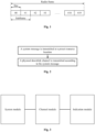
Fig. 1 is a structure diagram of an LTE system frame; -
Fig. 2 is a flowchart of a system message transmission method according to an embodiment of the invention; -
Fig. 3 is a structure diagram of a system message transmission device according to an embodiment of the invention; and -
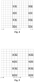
Fig. 4 to 7 are schematic diagrams of locations of narrowband reference signals according to an embodiment of the invention. - The embodiments of the invention will be described below in conjunction with the drawings. It should be noted that the embodiments in the present application and the features in the embodiments may be randomly combined with each other under the condition of no conflicts.
- A radio frame in an LTE system may follow frame structures in a Frequency Division Duplex (FDD) mode and a Time Division Duplex (TDD) mode. The frame structure in the FDD mode is as shown in
Fig. 1 . A radio frame of 10ms may consist of twenty slots of 0.5ms, numbered as 0 to 19, and slots 2i and 2i+1 may form a subframe i of 1ms. For a normal Cyclic Prefix (CP), each slot may contain 7 symbols of 66.7us, wherein the CP length of the first symbol is 5.21us, and the CP lengths of the other six symbols are 4.69us. For an extended CP, each slot may contain 6 symbols, and the CP length of all the symbols are 16.67us. - The number of CRS ports in the LTE system may be 1, 2 or 4, the number of CSI-RS ports may be 1, 2, 4 or 8. Different numbers of ports may correspond to different numbers of resource elements and different locations.
- A downlink control channel in the LTE system may be located on first n OFDM symbols of a subframe, n being 1, 2, 3 or 4.
- The NB-LTE system may adopt single-port transmission. In addition, because the bandwidth of the NB-LTE system is only 200k, time domain resources occupied by a PBCH and a synchronization signal of the NB-LTE system are increased relative to the LTE system. Therefore, a method for mapping a PBCH and a synchronization signal of an LTE system is no longer applicable, and therefore a new method is needed. Moreover, during spectrum sharing between the NB-LTE system and the LTE system, if the NB-LTE system does not avoid using resources used by a downlink control channel and a downlink reference signal of the LTE system and still works as if no spectrum is shared and resources are independently used, the interference between signals of different systems will be caused, and different systems simultaneously may transmit different signals over the same resource, thereby affecting UE data reception. Therefore, the NB-LTE system needs to send a system message to an NB-LTE UE to inform of available resources, in order that the NB-LTE system can perform data transmission according to whether a spectrum is shared. Meanwhile, consistency between the NB-LTE system and the NB-LTE UE is also ensured.
- As shown in
Fig. 2 , an embodiment of the invention provides a system message transmission method, including the steps as follows. - A system message may be transmitted at a preset resource location.
- A physical downlink channel may be transmitted according to the system message. The system message may include at least one of: frequency domain location information of a system, configuration information of a physical shared channel carrying a system message, configuration information of terminal access, available resource information of the physical downlink channel, and radio frame information.
- The physical downlink channel may include a physical downlink shared channel and/or a physical downlink control channel.
- The method in the embodiments of the invention is applied to NB-LTE.
- The transmission may include: sending and/or receiving.
- Herein, the available resource information of the physical downlink channel may include: information of a start OFDM symbol of the physical downlink channel in a subframe, and/or information of one or more unavailable resource elements of the physical downlink channel in a subframe, and/or information of one or more available subframes of the physical downlink channel.
- The information of one or more available subframes of the physical downlink channel may be indicated in one of the following alternative manners. The available subframes may be periodically indicated by using a bitmap. Alternatively, unavailable subframes may be periodically indicated by using a bitmap. For example, J bits may be used to indicate the availability of each subframe in J subframes. As such, each bit correspondingly indicates the availability of one subframe in J subframes, for example, 1 represents Available, and 0 represents Unavailable; or, 0 represents Available, and 1 represents Unavailable. Herein, J may be equal to 40, 80, 120, 160 or 240.
- The method may further include a step of indicating the information of the one or more unavailable resource elements via a CRS port location and/or a CSI-RS port location. The indication via the CRS port location and/or the CSI-RS port location may be determined by a number of ports and/or a virtual cell identity.
- The system message may be transmitted at the preset resource location in the following manner.
- The system message may be transmitted at the preset resource location via a PBCH.
- The PBCH may be located on last Y OFDM symbols of a first slot of a subframe and first X OFDM symbols of a second slot of the subframe.
- Herein, X may be equal to 4, 5, 6 or 7, and Y may be equal to 0, 1, 2, 3, 4 or 5.
- Alternatively, the PBCH may be located on any R OFDM symbols in first predefined OFDM symbols in a subframe, wherein R may be equal to 4, 5, 6 or 8. The first predefined OFDM symbols may include at least one of: a second OFDM symbol of each slot, a third OFDM symbol of each slot, a fourth last OFDM symbol of each slot, and last two OFDM symbols of each slot.
- In an embodiment, when R is equal to 4, the first predefined OFDM symbols may include last two OFDM symbols of each slot.
- In an embodiment, when R is equal to 5, the first predefined OFDM symbols may include last two OFDM symbols of each slot and a fourth last OFDM symbol of a second slot, or, the first predefined OFDM symbols may include last two OFDM symbols of each slot and a third OFDM symbol of a second slot.
- In an embodiment, when R is equal to 6, the first predefined OFDM symbols may include last two OFDM symbols of each slot, and a fourth last OFDM symbol and a second OFDM symbol of a second slot, or, the first predefined OFDM symbols may include last two OFDM symbols of each slot and a fourth last OFDM symbol of each slot, or, the first predefined OFDM symbols may include last two OFDM symbols of each slot, and a second OFDM symbol and a third OFDM symbol of a second slot.
- In an embodiment, when R is equal to 8, the first predefined OFDM symbols may include a second OFDM symbol, a third OFDM symbol and last two OFDM symbols of each slot.
- A narrowband reference signal may be transmitted on second predefined OFDM symbols. The second predefined OFDM symbols may include: last two OFDM symbols of each slot in a subframe, or, each OFDM symbol for transmitting the PBCH.
- The narrowband reference signal may be used to demodulate the PBCH, and the narrowband reference signal may be transmitted on one or more subframes for transmitting the PBCH.
- The number of antenna ports of the narrowband reference signal may be equal to 1 or 2. A frequency domain interval of reference signals of the same port may be 6 subcarriers, and a frequency domain location offset of reference signals of the same port on adjacent OFDM symbols may be 3 subcarriers.
- Initial locations of the antenna ports of the narrowband reference signal may be determined according to a cell identity.
- When a normal CP is adopted, as shown in
Fig. 4 andFig. 6 , 1 is an OFDM symbol index. - When an extended CP is adopted, as shown in
Fig. 5 andFig. 7 , 1 is an OFDM symbol index. - Herein, R0 indicates a first port, and R1 indicates a second port.
- In an embodiment, the first predefined symbols are OFDM symbols on which no CRS of the LTE system is sent. The transmission of a PBCH on the first predefined symbols may reduce influence of a CRS on the PBCH, and may particularly reduce mutual influence between a new system (narrowband system) and an LTE system on the same spectrum when cell identities corresponding to the two systems are different.
- In addition, the adoption of the specific first predefined symbols mentioned above mainly considers influence of the narrowband reference signal on demodulation performance. Specifically, an OFDM symbol carrying the PBCH is ensured to the greatest extent to be located on an OFDM symbol on which the narrowband reference signal is located. Preferably, the first predefined OFDM symbols are selected to be in an intermediate region on an OFDM symbol on which the narrowband reference signal is located, so that good transmission performance can be obtained.
- The PBCH and a synchronization channel may be located on adjacent subframes. Specifically, the locations of the PBCH and the synchronization channel may be embodied as one of the followings.
- The synchronization channel may be located on a
subframe # 9, and the PBCH may be located on asubframe # 0. - The synchronization channel may be located on a
subframe # 0, and the PBCH may be located on asubframe # 9. - The synchronization channel may be located on a subframe #8, and the PBCH may be located on a
subframe # 9. - The synchronization channel may be located on a subframe #6, and the PBCH may be located on a
subframe # 5. - The synchronization channel may be located on a subframe #4, and the PBCH may be located on a
subframe # 5. - The synchronization channel may be located on a
subframe # 5, and the PBCH may be located on a subframe #4. - The synchronization channel may be located on a
subframe # 3, and the PBCH may be located on a subframe #4. - The synchronization channel may be located on a
subframe # 1, and the PBCH may be located on asubframe # 0. - The PBCH may be mapped to T radio frames, and may be located on the same one or more subframes of each radio frame. T may be equal to 3, 6, 9, 18 or 36. The mapping mentioned herein refers to single transmission of the PBCH, and resource definition of a repeated transmission scenario of the PBCH is not involved.
- The one or more subframes may include one or more of a
subframe # 0 of a radio frame, a subframe #4 of a radio frame, asubframe # 5 of a radio frame, or asubframe # 9 of a radio frame. - The PBCH may be transmitted at an interval of Z1 radio frames, and may be repeatedly transmitted for Z2 times by every Z1 *Z2 radio frames. In the embodiment, Z1 may be equal to 4, 6, 8, 12 or 24, and Z2 may be equal to 4, 6, 8, 12 or 16.
- The system message may be transmitted at the preset resource location in one of the manners as follows.
- The system message may be transmitted at the preset resource location via a physical shared channel. Alternatively, the system message may be transmitted at the preset resource location via a physical shared channel and a PBCH. In the embodiment, a start OFDM symbol of a physical shared channel carrying the system message in a subframe may be a fixed value, and corresponding available resource elements may be remaining resources after a fixed virtual cell CRS port is removed.
- The location of the virtual cell CRS port may be the same as a resource location corresponding to a CRS port (single port, two ports, and four ports) in a relevant LTE system. The resource elements corresponding to a four-port CRS in the relevant LTE system may be selected to serve as resource elements corresponding to the virtual cell CRS port.
- The physical shared channel carrying the system message, the synchronization channel and the PBCH may be located on different subframes. One or more subframes of the physical shared channel carrying the system message may include one or more of a
subframe # 0, a subframe #4, asubframe # 5 and asubframe # 9. - For example, the synchronization channel and the PBCH may be located on the subframe #4 and the subframe #5 (the two subframes may be exchanged) of a radio frame respectively, and the physical shared channel carrying the system message may be located on the
subframe # 9 and/or thesubframe # 0. Alternatively, the synchronization channel and the PBCH may be located on thesubframe # 9 and the subframe #0 (the two subframes may be exchanged) of a radio frame respectively, and the physical shared channel carrying the system message may be located on the subframe #4 and/or thesubframe # 5. - The physical shared channel carrying the system message may be located on W successive radio frames, W being equal to 3, 6, 9 or 12.
- As shown in
Fig. 3 , a system message transmission device may include a system module and a channel module. - The system module may be configured to transmit a system message at a preset resource location.
- The channel module may be configured to transmit a physical downlink channel according to the system message. The system message may include at least one of: frequency domain location information of a system, configuration information of a physical shared channel carrying a system message, configuration information of terminal access, available resource information of the physical downlink channel, and radio frame information.
- The available resource information of the physical downlink channel may include: information of a start OFDM symbol of the physical downlink channel in a subframe, and/or information of one or more unavailable resource elements of the physical downlink channel in a subframe, and/or information of one or more available subframes of the physical downlink channel.
- The device may further include an indication module.
- The indication module may be configured to indicate the information of the one or more unavailable resource elements via a CRS port location and/or a CSI-RS port location.
- In an embodiment, the indication via the CRS port location and/or the CSI-RS port location may be determined by a number of ports and/or a virtual cell identity.
- Herein, the virtual cell identity is mainly used to indicate a cell identity of an LTE system during coexistence of a new system (narrowband system) and the LTE system, so that the reference signal location can be determined.
- The virtual cell identity may include an LTE cell identity or a predefined offset value, the predefined offset value being equal to 0, 1, 2, 3, 4 or 5.
- The information of one or more available subframes of the physical downlink channel may be indicated in one of the following alternative manners. The available subframes may be periodically indicated by using a bitmap. Alternatively, unavailable subframes may be periodically indicated by using a bitmap. For example, J bits may be used to indicate the availability of each subframe in J subframes. As such, each bit correspondingly indicates the availability of one subframe in J subframes, for example, 1 represents Available, and 0 represents Unavailable; or, 0 represents Available, and 1 represents Unavailable. Herein, J may be equal to 40, 80, 120, 160 or 240.
- The system module may be configured to transmit a system message at a preset resource location in the following manner.
- The system module may be configured to transmit the system message at the preset resource location via a PBCH.
- The preset resource location may be embodied as follows. The PBCH may be located on last Y OFDM symbols of a first slot of a subframe and first X OFDM symbols of a second slot of the subframe.
- In the embodiment, X may be equal to 4, 5, 6 or 7, and Y may be equal to 0, 1, 2, 3, 4 or 5.
- Alternatively, the PBCH may be located on any R OFDM symbols in first predefined OFDM symbols in a subframe, wherein R may be equal to 4, 5, 6 or 8. The first predefined OFDM symbols may include at least one of: a second OFDM symbol of each slot, a fourth last OFDM symbol of each slot, last two OFDM symbols of each slot, and a third OFDM symbol of each slot.
- In an embodiment, when R is equal to 4, the first predefined OFDM symbols may include last two OFDM symbols of each slot.
- In an embodiment, when R is equal to 5, the first predefined OFDM symbols may include last two OFDM symbols of each slot and a fourth last OFDM symbol of a second slot, or, the first predefined OFDM symbols may include last two OFDM symbols of each slot and a third OFDM symbol of a second slot.
- In an embodiment, when R is equal to 6, the first predefined OFDM symbols may include last two OFDM symbols of each slot, and a fourth last OFDM symbol and a second OFDM symbol of a second slot, or, the first predefined OFDM symbols may include last two OFDM symbols of each slot and a fourth last OFDM symbol of each slot, or, the first predefined OFDM symbols may include last two OFDM symbols of each slot, and a second OFDM symbol and a third OFDM symbol of a second slot.
- In an embodiment, when R is equal to 8, the first predefined OFDM symbols may include a second OFDM symbol, a third OFDM symbol and last two OFDM symbols of each slot.
- A narrowband reference signal may be transmitted on second predefined OFDM symbols. The second predefined OFDM symbols may include: last two OFDM symbols of each slot in a subframe, or, each OFDM symbol for transmitting the PBCH.
- The narrowband reference signal may be used to demodulate the PBCH, and the narrowband reference signal may be transmitted on one or more subframes for transmitting the PBCH.
- The number of antenna ports of the narrowband reference signal may be equal to 1 or 2. A frequency domain interval of reference signals of the same port may be 6 subcarriers, and a frequency domain location offset of reference signals of the same port on adjacent OFDM symbols may be 3 subcarriers.
- Initial locations of the antenna ports of the narrowband reference signal may be determined according to a cell identity.
- The PBCH and a synchronization channel may be located on adjacent subframes.
- The PBCH and a synchronization channel may be located on adjacent subframes. Specifically, the locations of the PBCH and the synchronization channel may be embodied as one of the followings.
- The synchronization channel may be located on a
subframe # 9, and the PBCH may be located on asubframe # 0. - The synchronization channel may be located on a
subframe # 0, and the PBCH may be located on asubframe # 9. - The synchronization channel may be located on a subframe #8, and the PBCH may be located on a
subframe # 9. - The synchronization channel may be located on a subframe #6, and the PBCH may be located on a
subframe # 5. - The synchronization channel may be located on a subframe #4, and the PBCH may be located on a
subframe # 5. - The synchronization channel may be located on a
subframe # 5, and the PBCH may be located on a subframe #4. - The synchronization channel may be located on a
subframe # 3, and the PBCH may be located on a subframe #4. - The synchronization channel may be located on a
subframe # 1, and the PBCH may be located on asubframe # 0. - The PBCH may be mapped to T radio frames, and may be located on the same one or more subframes of each radio frame.
- The one or more subframes may include one or more of a
subframe # 0 of a radio frame, a subframe #4 of a radio frame, asubframe # 5 of a radio frame, or asubframe # 9 of a radio frame. - The PBCH of the system module may be transmitted at an interval of Z1 radio frames, and may be repeatedly transmitted for Z2 times by every Z1*Z2 radio frames.
- In the embodiment, Z1 may be equal to 4, 6, 8, 12 or 24, and Z2 may be equal to 4, 6, 8, 12 or 16.
- The system module may be configured to transmit a system message at a preset resource location in one of the following manners.
- The system module may be configured to transmit the system message at the preset resource location via a physical shared channel. Alternatively, the system module may be configured to transmit the system message at the preset resource location via a physical shared channel and a PBCH.
- The system message may be transmitted at the preset resource location via the physical shared channel in a following manner.
- A start OFDM symbol of a physical shared channel carrying the system message in a subframe may be a fixed value, and corresponding available resource elements may be remaining resources after a fixed virtual cell CRS port is removed.
- The physical shared channel carrying the system message, the synchronization channel and the PBCH may be located on different subframes.
- One or more subframes of the physical shared channel carrying the system message may include one or more of a
subframe # 0, a subframe #4, asubframe # 5 and asubframe # 9. - The information of the start OFDM symbol may include two or four states.
- In the embodiment, a 1 bit signaling may be included to represent available resource information of the physical downlink channel.
- Two resource mapping modes may be predefined and indicated by 1 bit signaling. The available resource information of the physical downlink channel can be indicated by the signaling.
- For example, the first mapping mode may include: a physical downlink channel is mapped starting from a first OFDM symbol of a subframe, and/or corresponding available resource elements may be remaining resources after a fixed single-port virtual cell CRS is removed; and the second mapping mode may include: a physical downlink channel is mapped starting from a fourth OFDM symbol of a subframe, and/or corresponding available resource elements may be remaining resources after a fixed four-port virtual cell CRS is removed.
- the first mapping mode may include: a physical downlink channel is mapped starting from a first OFDM symbol of a subframe, and/or corresponding available resource elements may be remaining resources after a fixed single-port virtual cell CRS is removed; and the second mapping mode may include: a physical downlink channel is mapped starting from a fifth OFDM symbol of a subframe, and/or corresponding available resource elements may be remaining resources after a fixed four-port virtual cell CRS is removed.
- An alternative manner is: defining signaling respectively for the information of the start OFDM symbol of the physical downlink channel in a subframe and the information of one or more available resource elements of the physical downlink channel in a subframe.
- The information of the start OFDM symbol of the physical downlink channel in a subframe may occupy 1 bit, indicating a first OFDM symbol, or a kth OFDM symbol, where k is equal to 3, 4 or 5 optionally. Alternatively, the information of the start OFDM symbol of the physical downlink channel in a subframe may occupy 2 bits, indicating first, second, third or fourth OFDM symbol.
- The information of one or more available resource elements of the physical downlink channel in a subframe may be indicated via a CRS port location and/or a CSI-RS port location. The CRS port location may be 1, 2 or 4, or, the CRS port location may be 1 or 4.
- The CSI-RS port location may be Null, or may be one or more selected CSI-RS resource configuration indexes in a relevant LTE system. The CSI-RS port location being Null represents that no CSI-RS is sent.
- Because a CRS is only located on first two OFDM symbols on a subframe of an LTE system Multimedia Broadcast multicast service Signal Frequency Network (MBSFN) and a PBCH needs to be demodulated by the CRS and/or a synchronization channel, the PBCH may be located on non-MBSFN subframes (0, 4, 5, 9).
- Locating of a synchronization signal on an MBSFN subframe may avoid influence of a CRS of an LTE system on the synchronization signal. However, this may limit multicast service transmission. Therefore, a PBCH mapping solution is provided for two scenarios, i.e., a scenario in which the synchronization signal is located on MBSFN subframes (1, 2, 3, 6, 7, 8) and a scenario in which the synchronization signal is not located on MBSFN subframes (0, 4, 5, 9). The mapping solution may include transmitting the system message at the preset resource location via a PBCH.
- The preset resource location may be embodied as follows. The PBCH may be located on last Y OFDM symbols of a first slot of a subframe and first X OFDM symbols of a second slot of the subframe.
- In the embodiment, X may be equal to 4, 5, 6 or 7, and Y may be equal to 0, 1, 2, 3, 4 or 5.
- Alternatively, the PBCH may be located on any R OFDM symbols in first predefined OFDM symbols in a subframe, wherein R may be equal to 4, 5, 6 or 8, and the first predefined OFDM symbols may include at least one of: a second OFDM symbol of each slot, a fourth last OFDM symbol of each slot, last two OFDM symbols of each slot, and a third OFDM symbol of each slot.
- The above description indicates that a PBCH may be located on an adjacent subframe different from the subframe of a synchronization channel. However, it is not limited that a PBCH is present on an adjacent subframe of a synchronization channel for sure. The number of subframes occupied by the synchronization channel may be greater than or equal to the number of subframes occupied by the PBCH.
- For example, primary synchronization signals may be located on subframes #k of odd-indexed radio frames, and secondary synchronization signals may be located on subframes #k of even-indexed radio frames, wherein k may be equal to 1, 2, 3, 6, 7 or 8. Alternatively, primary synchronization signals may be located on subframes #k of even-indexed radio frames, and secondary synchronization signals may be located on subframes #k of odd-indexed radio frames, wherein k may be equal to 1, 2, 3, 6, 7 or 8. The subframes may be numbered starting from 0.
- Alternatively, the primary synchronization signals may be located on subframes #k of odd-indexed radio frames, and the secondary synchronization signals may be located on subframes #k of even-indexed radio frames, wherein k may be equal to 0, 4, 5 or 9. Alternatively, the primary synchronization signals may be located on subframes #k of even-indexed radio frames, and the secondary synchronization signals may be located on subframes #k of odd-indexed radio frames, wherein k may be equal to 0, 4, 5 or 9. The subframes may be numbered starting from 0.
- The PBCH may be mapped to a subframe #k of each radio frame by taking 6 successive radio frames as a period, wherein k may be equal to 0, 4, 5 or 9. Alternatively, the PBCH may be mapped to subframes #k of first three radio frames within each period by taking 6 successive radio frames as a period, wherein k may be equal to 0, 4, 5 or 9. Alternatively, the PBCH may be mapped to a subframe #k of each radio frame by taking 8 successive radio frames as a period, wherein k may be equal to 0, 4, 5 or 9.
- In this embodiment, the transmission may include: sending and/or receiving.
- The sending process may include steps as follows. An NB-LTE base station sends a system message to an NB-LTE terminal, and the NB-LTE base station sends a physical downlink channel to the NB-LTE terminal according to the system message.
- The NB-LTE base station may send a system message to the NB-LTE terminal at a preset resource location.
- The NB-LTE base station may send a physical downlink channel to the NB-LTE terminal according to the system message. The system message may include at least one of: frequency domain location information of a system, configuration information of a physical shared channel carrying a system message, configuration information of terminal access, available resource information of the physical downlink channel, and radio frame information.
- The NB-LTE frequency domain location information is mainly used to generate a CRS sequence. The CRS sequence may be generated based on an LTE system CRS sequence generation method. Therefore, it may be needed to determine a frequency domain location corresponding to NB-LTE to generate the CRS sequence.
- The configuration information of a physical shared channel carrying a system message may include at least one of: a number of bits for carrying the system message in the physical shared channel, a number of subframes occupied by the physical shared channel, and information of one or more radio frames occupied by the physical shared channel.
- The configuration information of terminal access includes whether terminal access is allowed, and optionally system state information, and/or configuration information of terminal uplink access resources.
- The system state information may be used for a terminal to determine whether and/or how to access the system.
- The available resource information of the physical downlink channel may include: information of a start OFDM symbol of the physical downlink channel in a subframe, and/or information of one or more unavailable resource elements of the physical downlink channel in a subframe, and/or information of one or more available subframes of the physical downlink channel.
- The information of one or more available subframes of the physical downlink channel may be indicated in one of the following manners. The available subframes may be indicated periodically by using a bitmap. Alternatively, unavailable subframes may be indicated periodically by using a bitmap. For example, J bits may be used to indicate the availability of each subframe in J subframes. As such, each bit correspondingly indicates the availability of one subframe in J subframes, for example, 1 represents Available, and 0 represents Unavailable; or, 0 represents Available, and 1 represents Unavailable. Herein, J may be 40, 80, 120, 160 or 240.
- The information of the one or more unavailable resource elements may be indicated via a CRS port location and/or a CSI-RS port location. The indication via the CRS port location and/or the CSI-RS port location may be determined by a number of ports and/or a virtual cell identity.
- The system message may be transmitted at a preset resource location in the following manner. The system message may be transmitted at a preset resource location via a PBCH.
- The preset resource location may be embodied as follows. The PBCH may be located on last Y OFDM symbols of a first slot of a subframe and first X OFDM symbols of a second slot of the subframe.
- In the embodiment, X may be equal to 4, 5, 6 or 7, and Y may be equal to 0, 1, 2, 3, 4 or 5.
- The PBCH may be located on any R OFDM symbols in first predefined OFDM symbols in a subframe, wherein R may be equal to 4, 5, 6 or 8. The first predefined OFDM symbols may include at least one of: a second OFDM symbol of each slot, a fourth last OFDM symbol of each slot, last two OFDM symbols of each slot, and a third OFDM symbol of each slot.
- In an embodiment, when R is equal to 4, the first predefined OFDM symbols may include last two OFDM symbols of each slot.
- In an embodiment, when R is equal to 5, the first predefined OFDM symbols may include last two OFDM symbols of each slot and a fourth last OFDM symbol of a second slot, or, the first predefined OFDM symbols may include last two OFDM symbols of each slot and a third OFDM symbol of a second slot.
- In an embodiment, when R is equal to 6, the first predefined OFDM symbols may include last two OFDM symbols of each slot, and a fourth last OFDM symbol and a second OFDM symbol of a second slot, or, the first predefined OFDM symbols may include last two OFDM symbols of each slot and a fourth last OFDM symbol of each slot, or, the first predefined OFDM symbols may include last two OFDM symbols of each slot, and a second OFDM symbol and a third OFDM symbol of a second slot.
- In an embodiment, when R is equal to 8, the first predefined OFDM symbols may include a second OFDM symbol, a third OFDM symbol and last two OFDM symbols of each slot.
- The PBCH and a synchronization channel may be located on adjacent subframes.
- The PBCH and a synchronization channel may be located on adjacent subframes which may be embodied as one of the following:
- the synchronization channel may be located on a
subframe # 9, and the PBCH may be located on asubframe # 0; - the synchronization channel may be located on a
subframe # 0, and the PBCH may be located on asubframe # 9; - the synchronization channel may be located on a subframe #8, and the PBCH may be located on a
subframe # 9; - the synchronization channel may be located on a subframe #6, and the PBCH may be located on a
subframe # 5; - the synchronization channel may be located on a subframe #4, and the PBCH may be located on a
subframe # 5; - the synchronization channel may be located on a
subframe # 5, and the PBCH may be located on a subframe #4; - the synchronization channel may be located on a
subframe # 3, and the PBCH may be located on a subframe #4; and - the synchronization channel may be located on a
subframe # 1, and the PBCH may be located on asubframe # 0. - The preset resource location may be embodied as follows. The PBCH may be mapped to T radio frames, and may be located on the same one or more subframes of each radio frame.
- The one or more subframes may include one or more of a
subframe # 0 of a radio frame, a subframe #4 of a radio frame, asubframe # 5 of a radio frame, or asubframe # 9 of a radio frame. - The PBCH may be transmitted at an interval of Z1 radio frames, and may be repeatedly transmitted for Z2 times by every Z1*Z2 radio frames.
- In the embodiment, Z1 may be equal to 4, 6, 8, 12 or 24, and Z2 may be equal to 4, 6, 8, 12 or 16.
- The system message may be transmitted at a preset resource location in one of the following manners.
- The system message may be transmitted at a preset resource location via a physical shared channel. Alternatively, the system message may be transmitted at a preset resource location via a physical shared channel and a PBCH.
- The system message may be transmitted at a preset resource location via a physical shared channel in the following manner.
- A start OFDM symbol of a physical shared channel carrying the system message in a subframe may be a fixed value, and corresponding available resource elements may be remaining resources after a fixed virtual cell CRS port is removed.
- The physical shared channel carrying the system message, the synchronization channel and the PBCH may be located on different subframes.
- One or more subframes of the physical shared channel carrying the system message may include one or more of a
subframe # 0, a subframe #4, asubframe # 5 and asubframe # 9. - The receiving process may include the following steps. The NB-LTE terminal receives a system message sent by the NB-LTE base station, and the NB-LTE terminal receives a physical downlink channel according to the system message.
- Herein, the system message may include at least one of: frequency domain location information of a system, configuration information of a physical shared channel carrying a system message, configuration information of terminal access, available resource information of the physical downlink channel, and radio frame information.
- The available resource information of the physical downlink channel may include: information of a start OFDM symbol of the physical downlink channel in a subframe, and/or information of one or more unavailable resource elements of the physical downlink channel in a subframe, and/or information of one or more available subframes of the physical downlink channel.
- The information of one or more available subframes of the physical downlink channel may be indicated in one of the following alternative manners. The available subframes may be indicated periodically by using a bitmap. Alternatively, the unavailable subframes may be indicated periodically by using a bitmap. For example, J bits may be used to indicate the availability of each subframe in J subframes. As such, each bit correspondingly indicates the availability of one subframe in J subframes, for example, 1 represents Available, and 0 represents Unavailable; or, 0 represents Available, and 1 represents Unavailable. Herein, J may be 40, 80, 120, 160 or 240.
- The information of the one or more unavailable resource elements may be indicated via a CRS port location and/or a CSI-RS port location. The indication via the CRS port location and/or the CSI-RS port location may be determined by a number of ports and/or a virtual cell identity.
- The system message may be transmitted at a preset resource location in the following manner. The system message may be transmitted at a preset resource location via a PBCH.
- The preset resource location may be embodied as follows. The PBCH may be located on last Y OFDM symbols of a first slot of a subframe and first X OFDM symbols of a second slot of the subframe.
- In the embodiment, X may be equal to 4, 5, 6 or 7, and Y may be equal to 0, 1, 2, 3, 4 or 5.
- The PBCH may be located on any R OFDM symbols in first predefined OFDM symbols in a subframe, wherein R may be equal to 4, 5, 6 or 8. The first predefined OFDM symbols may include at least one of: a second OFDM symbol of each slot, a fourth last OFDM symbol of each slot, last two OFDM symbols of each slot, and a third OFDM symbol of each slot.
- In an embodiment, when R is equal to 4, the first predefined OFDM symbols may include last two OFDM symbols of each slot.
- In an embodiment, when R is equal to 5, the first predefined OFDM symbols may include last two OFDM symbols of each slot and a fourth last OFDM symbol of a second slot, or, the first predefined OFDM symbols may include last two OFDM symbols of each slot and a third OFDM symbol of a second slot.
- In an embodiment, when R is equal to 6, the first predefined OFDM symbols may include last two OFDM symbols of each slot, and a fourth last OFDM symbol and a second OFDM symbol of a second slot, or, the first predefined OFDM symbols may include last two OFDM symbols of each slot and a fourth last OFDM symbol of each slot, or, the first predefined OFDM symbols may include last two OFDM symbols of each slot, and a second OFDM symbol and a third OFDM symbol of a second slot.
- In an embodiment, when R is equal to 8, the first predefined OFDM symbols may include a second OFDM symbol, a third OFDM symbol and last two OFDM symbols of each slot.
- The PBCH and a synchronization channel may be located on adjacent subframes.
- The PBCH and a synchronization channel may be located on adjacent subframes which may be embodied as one of the following:
- the synchronization channel may be located on a
subframe # 9, and the PBCH may be located on asubframe # 0; - the synchronization channel may be located on a
subframe # 0, and the PBCH may be located on asubframe # 9; - the synchronization channel may be located on a subframe #8, and the PBCH may be located on a
subframe # 9; - the synchronization channel may be located on a subframe #6, and the PBCH may be located on a
subframe # 5; - the synchronization channel may be located on a subframe #4, and the PBCH may be located on a
subframe # 5; - the synchronization channel may be located on a
subframe # 5, and the PBCH may be located on a subframe #4; - the synchronization channel may be located on a
subframe # 3, and the PBCH may be located on a subframe #4; and - the synchronization channel may be located on a
subframe # 1, and the PBCH may be located on asubframe # 0. - The preset resource location may be embodied as follows. The PBCH may be mapped to T radio frames, and may be located on the same one or more subframes of each radio frame.
- The one or more subframes may include one or more of a
subframe # 0 of a radio frame, a subframe #4 of a radio frame, asubframe # 5 of a radio frame, or asubframe # 9 of a radio frame. - The PBCH may be transmitted at an interval of Z1 radio frames, and may be repeatedly transmitted for Z2 times by every Z1*Z2 radio frames.
- In the embodiment, Z1 may be equal to 4, 6, 8, 12 or 24, and Z2 may be equal to 4, 6, 8, 12 or 16.
- The system message may be transmitted at a preset resource location in one of the following manners.
- The system message may be transmitted at a preset resource location via a physical shared channel. Alternatively, the system message may be transmitted at a preset resource location via a physical shared channel and a PBCH.
- The system message may be transmitted at a preset resource location via a physical shared channel in the following manner.
- A start OFDM symbol of a physical shared channel carrying the system message in a subframe may be a fixed value, and corresponding available resource elements may be remaining resources after a fixed virtual cell CRS port is removed.
- The physical shared channel carrying the system message, the synchronization channel and the PBCH may be located on different subframes.
- One or more subframes of the physical shared channel carrying the system message may include one or more of a
subframe # 0, a subframe #4, asubframe # 5 and asubframe # 9. - The system message may include available resource information and radio frame information of the physical downlink channel and may be carried by a PBCH.
- Two resource mapping modes are predefined, and indicated by 1 bit signaling. The available resource information of the physical downlink channel may be indicated by the signaling.
- The available resource information of the physical downlink channel may include information of a start OFDM symbol of the physical shared channel in a subframe and information of one or more available resource elements of the physical shared channel in a subframe.
- A first mapping mode may include: a physical downlink channel is mapped starting from a first OFDM symbol of a subframe, and corresponding available resource elements may be remaining resources after a fixed single-port virtual cell CRS is removed.
- A second mapping mode may include: a physical downlink channel is mapped starting from a fourth OFDM symbol of a subframe, and corresponding available resource elements may be remaining resources after a fixed four-port virtual cell CRS is removed.
- The synchronization channel may be located on a
subframe # 9 of a radio frame, and the PBCH may be located on asubframe # 0 of the radio frame. Alternatively, the PBCH may be located on asubframe # 9 of a radio frame, and the synchronization channel may be located on asubframe # 0 of the radio frame. Alternatively, the synchronization channel may be located on a subframe #4 of a radio frame, and the PBCH may be located on asubframe # 5 of the radio frame. Alternatively, the synchronization channel may be located on asubframe # 5 of a radio frame, and the PBCH may be located on a subframe #4 of the radio frame. - The PBCH may be located on last Y OFDM symbols of a first slot of a subframe and first X OFDM symbols of a second slot of the subframe, wherein X may be equal to 4, 5, 6 or 7, and Y may be equal to 0, 1, 2, 3, 4 or 5.
- The PBCH may be transmitted at an interval of Z1 radio frames, and may be repeatedly transmitted for Z2 times by every Z1*Z2 radio frames. Herein, Z1 may be equal to 6, 8, 12 or 24, and Z2 may be equal to 4, 6, 8, 12 or 16.
- For example, the symbol may include first four or five OFDM symbols of a second slot of a subframe, or, the last OFDM symbol of a first slot of a subframe and first four OFDM symbols of a second slot of the subframe, or, last two OFDM symbols of a first slot of a subframe and first four OFDM symbols of a second slot of the subframe, or, last two OFDM symbols of a first slot of a subframe and first six OFDM symbols of a second slot of the subframe, or, last three OFDM symbols of a first slot of a subframe and first five OFDM symbols of a second slot of the subframe, or, last five OFDM symbols of a first slot of a subframe and first seven OFDM symbols of a second slot of the subframe, or, last three OFDM symbols of a first slot of a subframe and all OFDM symbols of a second slot of the subframe.
- The mapping method may reduce the number of subframes for mapping a PBCH and reduce the transmission delay, and different CP types may adopt a unified design solution to the greatest extent.
- The PBCH may be mapped to six successive radio frames, and may be located on a fixed subframe #Y1 of each radio frame. Y1 may be equal to one or more of 0, 4, 5 and 9. The PBCH may be transmitted for four times within each period by taking 24 radio frames as a period.
- Alternatively, the PBCH may be mapped to first three successive radio frames of every six radio frames, and may be located on a fixed subframe #Y1 of each radio frame. Y1 may be equal to one or more of 0, 4, 5 and 9. The PBCH may be transmitted for four times within each period by taking 24 radio frames as a period.
- Alternatively, the PBCH may be mapped to eight successive radio frames, and may be located on a fixed subframe #Y1 of each radio frame. Y1 may be equal to one or more of 0, 4, 5 and 9. The PBCH may be transmitted for eight times within each period by taking 64 radio frames as a period.
- Alternatively, the PBCH may be mapped to eight successive radio frames, and may be located on a fixed subframe #Y1 of each radio frame. Y1 may be equal to one or more of 0, 4, 5 and 9. The PBCH may be transmitted for six times within each period by taking 48 radio frames as a period.
- Alternatively, the PBCH may be mapped to eight successive radio frames, and may be located on a fixed subframe #Y1 of each radio frame. Y1 may be equal to one or more of 0, 4, 5 and 9. The PBCH may be transmitted for 12 times within each period by taking 96 radio frames as a period.
- The system message may include frequency domain location information of a system, configuration information of a physical shared channel carrying a system message, configuration information of terminal access, and radio frame information. The system message may be carried by a PBCH.
- The synchronization channel may be located on a subframe #8 of a radio frame, and the PBCH may be located on a
subframe # 9 of the radio frame. Alternatively, the synchronization channel may be located on a subframe #6 of a radio frame, and the PBCH may be located on asubframe # 5 of the radio frame. Alternatively, the synchronization channel may be located on asubframe # 3 of a radio frame, and the PBCH may be located on a subframe #4 of the radio frame. Alternatively, the synchronization channel may be located on asubframe # 1 of a radio frame, and the PBCH may be located on asubframe # 0 of the radio frame. - The PBCH may be located on last Y OFDM symbols of a first slot of a subframe and first X OFDM symbols of a second slot of the subframe, wherein X may be equal to 4, 5, 6 or 7, and Y may be equal to 0, 1, 2, 3, 4 or 5.
- The PBCH may be transmitted at an interval of Z1 radio frames, and may be repeatedly transmitted for Z2 times by every Z1*Z2 radio frames. Z1 may be equal to 6, 8, 12 or 24, and Z2 may be equal to 4, 6, 8, 12 or 16.
- For example, the symbol may include first four or five OFDM symbols of a second slot of a subframe, or, the last OFDM symbol of a first slot of a subframe and first four OFDM symbols of a second slot of the subframe, or, last two OFDM symbols of a first slot of a subframe and first four OFDM symbols of a second slot of the subframe, or, last two OFDM symbols of a first slot of a subframe and first six OFDM symbols of a second slot of the subframe, or, last three OFDM symbols of a first slot of a subframe and first five OFDM symbols of a second slot of the subframe, or, last five OFDM symbols of a first slot of a subframe and first seven OFDM symbols of a second slot of the subframe, or, last three OFDM symbols of a first slot of a subframe and all OFDM symbols of a second slot of the subframe.
- The mapping method may reduce the number of subframes for mapping a PBCH and reduce the transmission delay. Different CP types may adopt a unified design solution to the greatest extent.
- The PBCH may be mapped to six successive radio frames, and may be located on a fixed subframe #Y1 of each radio frame. Y1 may be equal to one or more of 0, 4, 5 and 9. The PBCH may be transmitted for four times within each period by taking 24 radio frames as a period.
- Alternatively, the PBCH may be mapped to first three successive radio frames of every six radio frames, and may be located on a fixed subframe #Y1 of each radio frame. Y1 may be equal to one or more of 0, 4, 5 and 9. The PBCH may be transmitted for four times within each period by taking 24 radio frames as a period.
- The system message may include available resource information of the physical downlink channel, radio frame information, frequency domain location information of a system, configuration information of a physical shared channel carrying a system message, and configuration information of terminal access.
- The radio frame information, the NB-LTE frequency domain location information and the configuration information of the physical shared channel carrying the system message may be carried by a PBCH.
- The synchronization channel may be located on a subframe #8 of a radio frame, and the PBCH may be located on a
subframe # 9 of the radio frame. Alternatively, the synchronization channel may be located on a subframe #6 of a radio frame, and the PBCH may be located on asubframe # 5 of the radio frame. Alternatively, the synchronization channel may be located on asubframe # 3 of a radio frame, and the PBCH may be located on a subframe #4 of the radio frame. Alternatively, the synchronization channel may be located on asubframe # 1 of a radio frame, and the PBCH may be located on asubframe # 0 of the radio frame. - The PBCH may be located on last Y OFDM symbols of a first slot of a subframe and first X OFDM symbols of a second slot of the subframe, wherein X may be equal to 4, 5, 6 or 7, and Y may be equal to 0, 1, 2, 3, 4 or 5.
- The PBCH may be transmitted at an interval of Z1 radio frames, and may be repeatedly transmitted for Z2 times by every Z1*Z2 radio frames. Z1 may be equal to 6, 8, 12 or 24, and Z2 may be equal to 4, 6, 8, 12 or 16.
- For example, the symbol may include first four or five OFDM symbols of a second slot of a subframe, or, the last OFDM symbol of a first slot of a subframe and first four OFDM symbols of a second slot of the subframe, or, last two OFDM symbols of a first slot of a subframe and first four OFDM symbols of a second slot of the subframe, or, last two OFDM symbols of a first slot of a subframe and first six OFDM symbols of a second slot of the subframe, or, last three OFDM symbols of a first slot of a subframe and first five OFDM symbols of a second slot of the subframe, or, last five OFDM symbols of a first slot of a subframe and first seven OFDM symbols of a second slot of the subframe, or, last three OFDM symbols of a first slot of a subframe and all OFDM symbols of a second slot of the subframe.
- The mapping method may reduce the number of subframes for mapping a PBCH and reduce the transmission delay. Different CP types may adopt a unified design solution to the greatest extent.
- The PBCH may be mapped to six successive radio frames, and may be located on a fixed subframe #Y1 of each radio frame. Y1 may be equal to one or more of 0, 4, 5 and 9. The PBCH may be transmitted for four times within each period by taking 24 radio frames as a period.
- Alternatively, the PBCH may be mapped to first three successive radio frames of every six radio frames, and may be located on a fixed subframe #Y1 of each radio frame. Y1 may be equal to one or more of 0, 4, 5 and 9. The PBCH may be transmitted for four times within each period by taking 24 radio frames as a period.
- The available resource information of the physical downlink channel and the configuration information of terminal access may be carried by a PBCH. A start OFDM symbol of a physical shared channel carrying the system message in a subframe may be a first OFDM symbol, and corresponding available resource elements may be remaining resources after removing a 4-port virtual cell CRS port. The physical downlink shared channel may be transmitted in a single-port manner.
- Signaling is defined respectively for the information of the start OFDM symbol of the physical downlink channel in a subframe and information of one or more available resource elements of the physical downlink channel in a subframe.
- The information of the start OFDM symbol of the physical downlink channel in a subframe may occupy 1 bit, indicating a first OFDM symbol, or a kth OFDM symbol, where k may be equal to 3, 4 or 5. Alternatively, the information of the start OFDM symbol of the physical downlink channel in a subframe may occupy 2 bits, indicating the first, second, third or fourth OFDM symbol.
- The information of one or more available resource elements of the physical downlink channel in a subframe may be indicated via a CRS port location and/or a CSI-RS port location.
- Herein, the CRS port location may be 1, 2 or 4, or, the CRS port location may be 1 or 4. The CSI-RS port location may include Null, or may be one or more selected CSI-RS resource configuration indexes in a relevant LTE system.
- The physical shared channel carrying the system message, the synchronization channel and the PBCH may be located on different subframes.
- The one or more subframes of the physical shared channel carrying the system message may include one or more of a
subframe # 0, a subframe #4, asubframe # 5 and asubframe # 9. - The physical downlink channel may include a physical downlink shared channel and/or a physical downlink control channel.
- Another embodiment of the invention provides a computer storage medium in which a computer-executable instruction is stored. The computer-executable instruction is used to execute the method in the above-mentioned embodiments.
- Those of ordinary skill in the art may understand that all or some of the steps in the above-mentioned method may be completed by instructing relevant hardware (e.g., processor) through a program. The program may be stored in a computer-readable storage medium such as a read-only memory, a magnetic disk or an optical disk. Alternatively, all or some of the steps in the above-mentioned embodiments may be implemented by using one or more integrated circuits. Accordingly, each module/unit in the above-mentioned embodiments may be implemented in a form of hardware, and for example, corresponding functions thereof are implemented by means of an integrated circuit. Each module/unit may also be implemented in a form of software function module, and for example, corresponding functions thereof are implemented by executing programs/instructions stored in a memory by the processor. The invention is not limited to the combination of hardware and software in any specific form.
- Although the invention provides the implementation manners as above, the content is only the implementation manners illustrated for convenience of understanding the invention, and is not intended to limit the invention. Any person skilled in the art may make any modifications and changes about an implementation form and details without departing from the scope disclosed in the invention. However, the scope of protection limited by the invention should be determined with reference to the scope defined by the appended claims.
- The above-mentioned technical solutions can reduce the interference between signals during spectrum sharing between different systems and reduce the occurrence of simultaneous transmission of different signals over the same resource by different systems, thereby ensuring consistency between a system and a terminal, and improving the data transmission performance.
Claims (18)
- A system message transmission method for a narrowband long-term evolution, NB-LTE, system comprising:transmitting a system message at a preset resource location via a Physical Broadcast Channel, PBCH; andtransmitting a physical downlink channel according to the system message, wherein the system message comprises configuration information of terminal access, said method characterized in that configuration information of terminal access comprises whether a terminal is allowed to access the system;wherein the PBCH is demodulated by using a narrowband reference signal, and the narrowband reference signal is transmitted on the last two OFDM symbols of each slot in a subframe of the PBCH; or, the PBCH is demodulated by using a narrowband reference signal, and the narrowband reference signal is transmitted on each OFDM symbol for transmitting the PBCH.
- The method as claimed in claim 1, wherein the system message further comprises: frequency domain location information of the system.
- The method as claimed in claim 1, wherein the preset resource location comprises: the PBCH is located on last Y Orthogonal Frequency Division Multiplexing (OFDM) symbols of a first slot of a subframe and first X OFDM symbols of a second slot of the subframe, X comprising 4, 5, 6 or 7, and Y comprising 0, 1, 2, 3, 4 or 5.
- The method as claimed in claim 1, wherein the PBCH and a synchronization channel are located on adjacent subframes.
- The method as claimed in claim 4, wherein the PBCH and a synchronization channel are located on adjacent subframes comprises:
the synchronization channel is located on a subframe #9, and the PBCH is located on a subframe #0. - The method as claimed in claim 1, wherein the configuration information of terminal access further comprises at least one of: system state information, and configuration information of terminal uplink access resources, wherein the system state information is used for a terminal to determine whether and/or how to access the system.
- A system message transmission device for a narrowband long-term evolution, NB-LTE, system comprising:a system module, configured to transmit a system message at a preset resource location via a Physical Broadcast Channel, PBCH; anda channel module, configured to transmit a physical downlink channel according to the system message, wherein the system message comprises configuration information of terminal access, said device characterized in that configuration information of terminal access comprises whether a terminal is allowed to access the system;wherein the PBCH is demodulated by using a narrowband reference signal, and the narrowband reference signal is transmitted on the last two OFDM symbols of each slot in a subframe of the PBCH; or, the PBCH is demodulated by using a narrowband reference signal, and the narrowband reference signal is transmitted on each OFDM symbol for transmitting the PBCH.
- The device as claimed in claim 7, wherein the system message further comprises: frequency domain location information of the system.
- The device as claimed in claim 7, wherein the preset resource location comprises: the PBCH is located on last Y OFDM symbols of a first slot of a subframe and first X OFDM symbols of a second slot of the subframe, X comprising 4, 5, 6 or 7, and Y comprising 0, 1, 2, 3, 4 or 5.
- The device as claimed in claim 7, wherein the PBCH and a synchronization channel are located on adjacent subframes.
- The device as claimed in claim 10, wherein the PBCH and a synchronization channel being located on adjacent subframes comprises:
the synchronization channel is located on a subframe #9, and the PBCH is located on a subframe #0. - The device as claimed in claim 7, wherein the configuration information of terminal access further comprises at least one of: system state information, and configuration information of terminal uplink access resources, wherein the system state information is used for a terminal to determine whether and/or how to access the system.
- A system message transmission method for a narrowband long-term evolution, NB-LTE, system comprising:receiving, by an NB-LTE terminal, a system message at a preset resource location via a Physical Broadcast Channel, PBCH; andreceiving, by the NB-LTE terminal, a physical downlink channel according to the system message, wherein the system message comprises configuration information of terminal access, said method characterized in that the configuration information of terminal access comprises whether the terminal is allowed to access the system;wherein the PBCH is demodulated by using a narrowband reference signal, and the narrowband reference signal is transmitted on the last two OFDM symbols of each slot in a subframe of the PBCH; or, the PBCH is demodulated by using a narrowband reference signal, and the narrowband reference signal is transmitted on each OFDM symbol for transmitting the PBCH.
- The method as claimed in claim 13, wherein the PBCH and a synchronization channel are located on adjacent subframes.
- The method as claimed in claim 14, wherein the synchronization channel is located on a subframe #9, and the PBCH is located on a subframe #0.
- A terminal device for a narrowband long-term evolution, NB-LTE, system comprising:a communication module, configured to receive a system message at a preset resource location via a Physical Broadcast Channel, PBCH, andto receive a physical downlink channel according to the system message, wherein the system message comprises configuration information of terminal access,said device characterized in that the configuration information of terminal access comprises whether the terminal is allowed to access the system;wherein the PBCH is demodulated by using a narrowband reference signal, and the narrowband reference signal is transmitted on the last two OFDM symbols of each slot in a subframe of the PBCH; or, the PBCH is demodulated by using a narrowband reference signal, and the narrowband reference signal is transmitted on each OFDM symbol for transmitting the PBCH.
- The device as claimed in claim 16, wherein the PBCH and a synchronization channel are located on adjacent subframes.
- The device as claimed in claim 17, wherein the synchronization channel is located on a subframe #9, and the PBCH is located on a subframe #0.
Priority Applications (1)
| Application Number | Priority Date | Filing Date | Title |
|---|---|---|---|
| EP24167897.8A EP4373195A3 (en) | 2015-09-02 | 2016-08-30 | System message transmission method and device |
Applications Claiming Priority (3)
| Application Number | Priority Date | Filing Date | Title |
|---|---|---|---|
| CN201510557207 | 2015-09-02 | ||
| CN201510567936.7A CN106488509B (en) | 2015-09-02 | 2015-09-08 | System message transmission method and device |
| PCT/CN2016/097379 WO2017036385A1 (en) | 2015-09-02 | 2016-08-30 | System message transmission method and device |
Related Child Applications (2)
| Application Number | Title | Priority Date | Filing Date |
|---|---|---|---|
| EP24167897.8A Division EP4373195A3 (en) | 2015-09-02 | 2016-08-30 | System message transmission method and device |
| EP24167897.8A Division-Into EP4373195A3 (en) | 2015-09-02 | 2016-08-30 | System message transmission method and device |
Publications (3)
| Publication Number | Publication Date |
|---|---|
| EP3346757A1 EP3346757A1 (en) | 2018-07-11 |
| EP3346757A4 EP3346757A4 (en) | 2018-08-29 |
| EP3346757B1 true EP3346757B1 (en) | 2024-07-10 |
Family
ID=58238127
Family Applications (2)
| Application Number | Title | Priority Date | Filing Date |
|---|---|---|---|
| EP16840814.4A Active EP3346757B1 (en) | 2015-09-02 | 2016-08-30 | System message transmission method and device |
| EP24167897.8A Pending EP4373195A3 (en) | 2015-09-02 | 2016-08-30 | System message transmission method and device |
Family Applications After (1)
| Application Number | Title | Priority Date | Filing Date |
|---|---|---|---|
| EP24167897.8A Pending EP4373195A3 (en) | 2015-09-02 | 2016-08-30 | System message transmission method and device |
Country Status (6)
| Country | Link |
|---|---|
| US (3) | US20180279257A1 (en) |
| EP (2) | EP3346757B1 (en) |
| JP (3) | JP7110092B2 (en) |
| KR (2) | KR20240014628A (en) |
| CN (1) | CN106488509B (en) |
| DK (1) | DK3346757T3 (en) |
Families Citing this family (11)
| Publication number | Priority date | Publication date | Assignee | Title |
|---|---|---|---|---|
| CN106488509B (en) | 2015-09-02 | 2021-10-19 | 中兴通讯股份有限公司 | System message transmission method and device |
| CN108632738A (en) * | 2017-03-24 | 2018-10-09 | 中兴通讯股份有限公司 | Transmission method, device, storage medium and the processor of information |
| US10560237B2 (en) * | 2017-05-30 | 2020-02-11 | Qualcomm Incorporated | Cell-specific reference signal transmissions for evolved machine type communication |
| WO2018229964A1 (en) * | 2017-06-16 | 2018-12-20 | 株式会社Nttドコモ | Base station device |
| JP7210481B2 (en) | 2017-06-21 | 2023-01-23 | エルジー エレクトロニクス インコーポレイティド | Method and apparatus for transmitting and receiving synchronization signals in wireless communication system |
| CN110383881B (en) * | 2017-07-12 | 2021-06-01 | 华为技术有限公司 | Information sending and receiving method and equipment |
| CN117793919A (en) * | 2017-11-17 | 2024-03-29 | 中兴通讯股份有限公司 | Information sending and receiving method and device |
| CN110048820B (en) * | 2018-01-16 | 2021-11-19 | 中国移动通信有限公司研究院 | Configuration method, feedback method and device of channel state information |
| EP3806374B1 (en) * | 2019-10-11 | 2022-03-09 | Shenzhen Goodix Technology Co., Ltd. | Method for enhancement of neighbor cell interference robustness for nb-iot |
| CN113811005B (en) * | 2020-06-12 | 2024-05-07 | 联发科技(新加坡)私人有限公司 | Method and apparatus for multiple systems or multiple subsystems sharing frame configuration |
| WO2023173381A1 (en) * | 2022-03-17 | 2023-09-21 | 北京小米移动软件有限公司 | Sidelink communication methods and apparatuses |
Citations (4)
| Publication number | Priority date | Publication date | Assignee | Title |
|---|---|---|---|---|
| GB2491866A (en) * | 2011-06-15 | 2012-12-19 | Sca Ipla Holdings Inc | Allowing machine type communication devices to camp on a carrier even in the presence of higher bandwidth carriers |
| US20130077582A1 (en) * | 2011-09-23 | 2013-03-28 | Samsung Electronics Co., Ltd. | System access method and apparatus of a narrowband terminal in a wireless communication system supporting wideband and narrowband terminals |
| WO2015080649A1 (en) * | 2013-11-27 | 2015-06-04 | Telefonaktiebolaget L M Ericsson (Publ) | Sending and detecting synchronization signals and an associated information message |
| US20150230211A1 (en) * | 2012-09-25 | 2015-08-13 | Lg Electronics Inc. | Method for receiving downlink signal, and user device; and method for transmitting downlink signal, and base station |
Family Cites Families (16)
| Publication number | Priority date | Publication date | Assignee | Title |
|---|---|---|---|---|
| US8982759B2 (en) * | 2009-01-15 | 2015-03-17 | Lg Electronics Inc. | System information transmitting and receiving device |
| CN102026375B (en) | 2009-09-11 | 2013-10-23 | 中国移动通信集团公司 | Method, system and apparatus for system information transmission |
| CN102065516A (en) * | 2009-11-17 | 2011-05-18 | 华为技术有限公司 | Method and device for transmitting system message |
| CN108234103B (en) | 2012-01-11 | 2023-06-20 | 三星电子株式会社 | Method and apparatus for wireless communication |
| KR102094050B1 (en) * | 2012-01-27 | 2020-03-27 | 인터디지탈 패튼 홀딩스, 인크 | Systems and/or methods for providing epdcch in a multiple carrier based and/or quasi-collated network |
| US8948123B2 (en) | 2012-02-01 | 2015-02-03 | Fujitsu Limited | Enhanced control signals multiplexed with data signals |
| EP2847917B1 (en) * | 2012-05-11 | 2018-10-31 | Telefonaktiebolaget LM Ericsson (publ) | Apparatus and method for downlink scheduling |
| JP5797184B2 (en) | 2012-09-13 | 2015-10-21 | テックワン株式会社 | Waterproof and moisture-permeable composite membrane and waterproof and moisture-permeable fabric having waterproof and moisture-permeable composite membrane |
| EP2919538B1 (en) | 2012-11-09 | 2017-10-11 | Sharp Kabushiki Kaisha | User equipment, base station device, communication methods and integrated circuits |
| CN103906139B (en) * | 2012-12-27 | 2018-10-30 | 夏普株式会社 | The method of sending and receiving of system information and base station and user equipment |
| EP3448105B1 (en) * | 2013-09-24 | 2021-07-14 | Sony Corporation | Communication control device, communication control method, terminal device, and information processing device |
| GB2522482A (en) * | 2014-01-28 | 2015-07-29 | Nec Corp | Communication system |
| KR20160031896A (en) | 2014-09-15 | 2016-03-23 | 엘지전자 주식회사 | Mobile terminal |
| WO2017039739A1 (en) * | 2015-09-02 | 2017-03-09 | Intel IP Corporation | Methods and apparatuses for channel estimation for nb-pbch in nb-lte systems |
| CN106488509B (en) | 2015-09-02 | 2021-10-19 | 中兴通讯股份有限公司 | System message transmission method and device |
| US10517083B2 (en) * | 2015-09-25 | 2019-12-24 | Lg Electronics Inc. | Method and user equipment for receiving downlink control information, and method and base station for transmitting downlink control information |
-
2015
- 2015-09-08 CN CN201510567936.7A patent/CN106488509B/en active Active
-
2016
- 2016-08-30 JP JP2018511614A patent/JP7110092B2/en active Active
- 2016-08-30 KR KR1020247002910A patent/KR20240014628A/en not_active Application Discontinuation
- 2016-08-30 EP EP16840814.4A patent/EP3346757B1/en active Active
- 2016-08-30 EP EP24167897.8A patent/EP4373195A3/en active Pending
- 2016-08-30 DK DK16840814.4T patent/DK3346757T3/en active
- 2016-08-30 KR KR1020187009224A patent/KR102630964B1/en active IP Right Grant
- 2016-08-30 US US15/757,152 patent/US20180279257A1/en not_active Abandoned
-
2020
- 2020-10-01 US US17/060,141 patent/US11606775B2/en active Active
-
2022
- 2022-06-06 JP JP2022091400A patent/JP7368549B2/en active Active
-
2023
- 2023-02-08 US US18/107,046 patent/US20230189297A1/en active Pending
- 2023-10-12 JP JP2023176744A patent/JP2023179683A/en active Pending
Patent Citations (4)
| Publication number | Priority date | Publication date | Assignee | Title |
|---|---|---|---|---|
| GB2491866A (en) * | 2011-06-15 | 2012-12-19 | Sca Ipla Holdings Inc | Allowing machine type communication devices to camp on a carrier even in the presence of higher bandwidth carriers |
| US20130077582A1 (en) * | 2011-09-23 | 2013-03-28 | Samsung Electronics Co., Ltd. | System access method and apparatus of a narrowband terminal in a wireless communication system supporting wideband and narrowband terminals |
| US20150230211A1 (en) * | 2012-09-25 | 2015-08-13 | Lg Electronics Inc. | Method for receiving downlink signal, and user device; and method for transmitting downlink signal, and base station |
| WO2015080649A1 (en) * | 2013-11-27 | 2015-06-04 | Telefonaktiebolaget L M Ericsson (Publ) | Sending and detecting synchronization signals and an associated information message |
Also Published As
| Publication number | Publication date |
|---|---|
| EP4373195A3 (en) | 2024-07-31 |
| JP7368549B2 (en) | 2023-10-24 |
| EP3346757A4 (en) | 2018-08-29 |
| US11606775B2 (en) | 2023-03-14 |
| KR20180048956A (en) | 2018-05-10 |
| EP4373195A2 (en) | 2024-05-22 |
| KR20240014628A (en) | 2024-02-01 |
| DK3346757T3 (en) | 2024-08-05 |
| US20230189297A1 (en) | 2023-06-15 |
| CN106488509A (en) | 2017-03-08 |
| JP2022122973A (en) | 2022-08-23 |
| CN106488509B (en) | 2021-10-19 |
| US20210029672A1 (en) | 2021-01-28 |
| JP7110092B2 (en) | 2022-08-01 |
| EP3346757A1 (en) | 2018-07-11 |
| US20180279257A1 (en) | 2018-09-27 |
| JP2018527834A (en) | 2018-09-20 |
| JP2023179683A (en) | 2023-12-19 |
| KR102630964B1 (en) | 2024-01-29 |
Similar Documents
| Publication | Publication Date | Title |
|---|---|---|
| EP3346757B1 (en) | System message transmission method and device | |
| CN109803402B (en) | Information sending and receiving method and device | |
| CA3064617C (en) | Random access method, terminal, and network device | |
| AU2021215138B2 (en) | Method for configuring transmission direction of time-frequency resource, and apparatus | |
| EP3151601B1 (en) | Information sending method, information receiving method and apparatus | |
| CN102594513B (en) | Enhanced downlink control signal channel transmission method and device | |
| EP2945454B1 (en) | Methods and devices for sending control information and receiving control information | |
| WO2014113961A1 (en) | Method for transmitting reference signal, base station and user equipment | |
| JP7004467B2 (en) | Methods and Devices for Transmitting Narrowband Orthogonal Frequency Division Multiplexed Signals | |
| CN111867038B (en) | Communication method and device | |
| CN108432285B (en) | Transmission method, device and system of physical downlink channel | |
| EP3637818B1 (en) | Signal sending and receiving method and device | |
| CN104081698B (en) | Method for transceiving downlink control channel in wireless communication system and apparatus therefor | |
| WO2021092900A1 (en) | Method and apparatus for wireless communication | |
| CN109803371B (en) | Communication processing method and device | |
| WO2017036385A1 (en) | System message transmission method and device | |
| US11962521B2 (en) | Radio communication apparatus, method, program, non-transitory computer readable recording medium, and system | |
| EP4188005A1 (en) | Resource configuration method and apparatus |
Legal Events
| Date | Code | Title | Description |
|---|---|---|---|
| STAA | Information on the status of an ep patent application or granted ep patent |
Free format text: STATUS: THE INTERNATIONAL PUBLICATION HAS BEEN MADE |
|
| PUAI | Public reference made under article 153(3) epc to a published international application that has entered the european phase |
Free format text: ORIGINAL CODE: 0009012 |
|
| STAA | Information on the status of an ep patent application or granted ep patent |
Free format text: STATUS: REQUEST FOR EXAMINATION WAS MADE |
|
| 17P | Request for examination filed |
Effective date: 20180313 |
|
| AK | Designated contracting states |
Kind code of ref document: A1 Designated state(s): AL AT BE BG CH CY CZ DE DK EE ES FI FR GB GR HR HU IE IS IT LI LT LU LV MC MK MT NL NO PL PT RO RS SE SI SK SM TR |
|
| AX | Request for extension of the european patent |
Extension state: BA ME |
|
| A4 | Supplementary search report drawn up and despatched |
Effective date: 20180730 |
|
| RIC1 | Information provided on ipc code assigned before grant |
Ipc: H04L 5/00 20060101AFI20180724BHEP Ipc: H04W 72/12 20090101ALI20180724BHEP Ipc: H04W 28/08 20090101ALI20180724BHEP |
|
| DAV | Request for validation of the european patent (deleted) | ||
| DAX | Request for extension of the european patent (deleted) | ||
| STAA | Information on the status of an ep patent application or granted ep patent |
Free format text: STATUS: EXAMINATION IS IN PROGRESS |
|
| 17Q | First examination report despatched |
Effective date: 20190521 |
|
| STAA | Information on the status of an ep patent application or granted ep patent |
Free format text: STATUS: EXAMINATION IS IN PROGRESS |
|
| STAA | Information on the status of an ep patent application or granted ep patent |
Free format text: STATUS: EXAMINATION IS IN PROGRESS |
|
| GRAP | Despatch of communication of intention to grant a patent |
Free format text: ORIGINAL CODE: EPIDOSNIGR1 |
|
| STAA | Information on the status of an ep patent application or granted ep patent |
Free format text: STATUS: GRANT OF PATENT IS INTENDED |
|
| INTG | Intention to grant announced |
Effective date: 20240206 |
|
| GRAS | Grant fee paid |
Free format text: ORIGINAL CODE: EPIDOSNIGR3 |
|
| GRAA | (expected) grant |
Free format text: ORIGINAL CODE: 0009210 |
|
| STAA | Information on the status of an ep patent application or granted ep patent |
Free format text: STATUS: THE PATENT HAS BEEN GRANTED |
|
| AK | Designated contracting states |
Kind code of ref document: B1 Designated state(s): AL AT BE BG CH CY CZ DE DK EE ES FI FR GB GR HR HU IE IS IT LI LT LU LV MC MK MT NL NO PL PT RO RS SE SI SK SM TR |
|
| REG | Reference to a national code |
Ref country code: CH Ref legal event code: EP |
|
| REG | Reference to a national code |
Ref country code: DE Ref legal event code: R096 Ref document number: 602016088372 Country of ref document: DE |
|
| REG | Reference to a national code |
Ref country code: DK Ref legal event code: T3 Effective date: 20240801 |
|
| REG | Reference to a national code |
Ref country code: SE Ref legal event code: TRGR |
|
| REG | Reference to a national code |
Ref country code: NL Ref legal event code: FP |
|
| PGFP | Annual fee paid to national office [announced via postgrant information from national office to epo] |
Ref country code: NL Payment date: 20240712 Year of fee payment: 9 |