EP3346675A1 - Display screen assembly, manufacturing method thereof and electronic device - Google Patents
Display screen assembly, manufacturing method thereof and electronic device Download PDFInfo
- Publication number
- EP3346675A1 EP3346675A1 EP17187504.0A EP17187504A EP3346675A1 EP 3346675 A1 EP3346675 A1 EP 3346675A1 EP 17187504 A EP17187504 A EP 17187504A EP 3346675 A1 EP3346675 A1 EP 3346675A1
- Authority
- EP
- European Patent Office
- Prior art keywords
- display screen
- cover plate
- bracket
- joining part
- decoration enclosure
- Prior art date
- Legal status (The legal status is an assumption and is not a legal conclusion. Google has not performed a legal analysis and makes no representation as to the accuracy of the status listed.)
- Granted
Links
Images


Classifications
-
- G—PHYSICS
- G06—COMPUTING OR CALCULATING; COUNTING
- G06F—ELECTRIC DIGITAL DATA PROCESSING
- G06F3/00—Input arrangements for transferring data to be processed into a form capable of being handled by the computer; Output arrangements for transferring data from processing unit to output unit, e.g. interface arrangements
- G06F3/01—Input arrangements or combined input and output arrangements for interaction between user and computer
- G06F3/03—Arrangements for converting the position or the displacement of a member into a coded form
- G06F3/041—Digitisers, e.g. for touch screens or touch pads, characterised by the transducing means
- G06F3/0412—Digitisers structurally integrated in a display
-
- B—PERFORMING OPERATIONS; TRANSPORTING
- B22—CASTING; POWDER METALLURGY
- B22D—CASTING OF METALS; CASTING OF OTHER SUBSTANCES BY THE SAME PROCESSES OR DEVICES
- B22D19/00—Casting in, on, or around objects which form part of the product
- B22D19/04—Casting in, on, or around objects which form part of the product for joining parts
-
- G—PHYSICS
- G02—OPTICS
- G02F—OPTICAL DEVICES OR ARRANGEMENTS FOR THE CONTROL OF LIGHT BY MODIFICATION OF THE OPTICAL PROPERTIES OF THE MEDIA OF THE ELEMENTS INVOLVED THEREIN; NON-LINEAR OPTICS; FREQUENCY-CHANGING OF LIGHT; OPTICAL LOGIC ELEMENTS; OPTICAL ANALOGUE/DIGITAL CONVERTERS
- G02F1/00—Devices or arrangements for the control of the intensity, colour, phase, polarisation or direction of light arriving from an independent light source, e.g. switching, gating or modulating; Non-linear optics
- G02F1/01—Devices or arrangements for the control of the intensity, colour, phase, polarisation or direction of light arriving from an independent light source, e.g. switching, gating or modulating; Non-linear optics for the control of the intensity, phase, polarisation or colour
- G02F1/13—Devices or arrangements for the control of the intensity, colour, phase, polarisation or direction of light arriving from an independent light source, e.g. switching, gating or modulating; Non-linear optics for the control of the intensity, phase, polarisation or colour based on liquid crystals, e.g. single liquid crystal display cells
- G02F1/133—Constructional arrangements; Operation of liquid crystal cells; Circuit arrangements
- G02F1/1333—Constructional arrangements; Manufacturing methods
- G02F1/13338—Input devices, e.g. touch panels
-
- G—PHYSICS
- G06—COMPUTING OR CALCULATING; COUNTING
- G06F—ELECTRIC DIGITAL DATA PROCESSING
- G06F1/00—Details not covered by groups G06F3/00 - G06F13/00 and G06F21/00
- G06F1/16—Constructional details or arrangements
- G06F1/1613—Constructional details or arrangements for portable computers
- G06F1/1626—Constructional details or arrangements for portable computers with a single-body enclosure integrating a flat display, e.g. Personal Digital Assistants [PDAs]
-
- H—ELECTRICITY
- H04—ELECTRIC COMMUNICATION TECHNIQUE
- H04M—TELEPHONIC COMMUNICATION
- H04M1/00—Substation equipment, e.g. for use by subscribers
- H04M1/02—Constructional features of telephone sets
- H04M1/0202—Portable telephone sets, e.g. cordless phones, mobile phones or bar type handsets
- H04M1/026—Details of the structure or mounting of specific components
- H04M1/0266—Details of the structure or mounting of specific components for a display module assembly
-
- B—PERFORMING OPERATIONS; TRANSPORTING
- B29—WORKING OF PLASTICS; WORKING OF SUBSTANCES IN A PLASTIC STATE IN GENERAL
- B29C—SHAPING OR JOINING OF PLASTICS; SHAPING OF MATERIAL IN A PLASTIC STATE, NOT OTHERWISE PROVIDED FOR; AFTER-TREATMENT OF THE SHAPED PRODUCTS, e.g. REPAIRING
- B29C45/00—Injection moulding, i.e. forcing the required volume of moulding material through a nozzle into a closed mould; Apparatus therefor
- B29C45/14—Injection moulding, i.e. forcing the required volume of moulding material through a nozzle into a closed mould; Apparatus therefor incorporating preformed parts or layers, e.g. injection moulding around inserts or for coating articles
- B29C45/14467—Joining articles or parts of a single article
-
- G—PHYSICS
- G06—COMPUTING OR CALCULATING; COUNTING
- G06F—ELECTRIC DIGITAL DATA PROCESSING
- G06F2203/00—Indexing scheme relating to G06F3/00 - G06F3/048
- G06F2203/041—Indexing scheme relating to G06F3/041 - G06F3/045
- G06F2203/04103—Manufacturing, i.e. details related to manufacturing processes specially suited for touch sensitive devices
-
- H—ELECTRICITY
- H04—ELECTRIC COMMUNICATION TECHNIQUE
- H04M—TELEPHONIC COMMUNICATION
- H04M1/00—Substation equipment, e.g. for use by subscribers
- H04M1/02—Constructional features of telephone sets
- H04M1/0202—Portable telephone sets, e.g. cordless phones, mobile phones or bar type handsets
- H04M1/0279—Improving the user comfort or ergonomics
- H04M1/0283—Improving the user comfort or ergonomics for providing a decorative aspect, e.g. customization of casings, exchangeable faceplate
-
- H—ELECTRICITY
- H04—ELECTRIC COMMUNICATION TECHNIQUE
- H04M—TELEPHONIC COMMUNICATION
- H04M2250/00—Details of telephonic subscriber devices
- H04M2250/22—Details of telephonic subscriber devices including a touch pad, a touch sensor or a touch detector
Definitions
- the present disclosure relates to a technical field of mobile electronic devices, particularly to a display screen assembly, an electronic device and a manufacturing method of the display screen assembly.
- smartphones are used more and more widely and have more and more functions, and smartphones have become requisite electronic apparatuses in people's daily lives.
- large-screen smartphones have a larger display area to meet a user's requirements for browsing web pages, reading books, watching videos, playing games and so on.
- the bezel of the smartphone is getting narrower to increase a screen-to-body ratio so as to improve user experience.
- the narrower the bezels of the smartphones are, the greater of the difficulties of assembling a display screen and a cover plate in the smartphones.
- Embodiments of the present disclosure provide a display screen assembly, an electronic device and a manufacturing method of the display screen assembly.
- a display screen assembly includes a bracket, a display screen, a cover plate and a decoration enclosure.
- the bracket includes a bottom wall and a side wall bending from the bottom wall.
- the display screen includes a top surface and a bottom surface, the bottom surface of the display screen is provided on the bottom wall of the bracket, and the display screen and the side wall of the bracket are located at two opposite sides of the bottom wall of the bracket respectively.
- a bottom surface of the cover plate is joined with the top surface of the display screen, and the cover plate has a groove at a side wall thereof.
- the decoration enclosure includes a first joining part and a second joining part coupled to each other, the first joining part is received in the groove, and the second joining part is joined with the side wall of the bracket.
- the second joining part is joined with the side wall of the bracket by one or a combination of ones of adhering, screwing, snap and welding.
- the bottom surface of the cover plate is screen-printed with a black-ink edge
- the top surface of the display screen defines a non-display area
- the black-ink edge shields the non-display area
- the decoration enclosure is joined with the cover plate by means of in-mold injection molding.
- the top surface of the display screen is joined with the bottom surface of the cover plate in a full lamination manner.
- the top surface of the display screen is laminated with the bottom surface of the cover plate through an optically clear adhesive (OCA).
- OCA optically clear adhesive
- the bottom surface of the display screen is joined with the bottom wall of the bracket in an adhering manner.
- the cover plate is configured as a touch-screen cover plate.
- an outer surface of the decoration enclosure is configured as an arc surface.
- an electronic device includes a display screen assembly according to any embodiment described above and a rear cover coupled to the display screen assembly.
- the rear cover is snapped with the decoration enclosure.
- the decoration enclosure is provided with a boss at a side thereof, the rear cover has a groove corresponding to the boss, and the boss is configured to be snapped into the groove of the rear cover to couple the rear cover with the decoration enclosure.
- a manufacturing method of a display screen assembly includes:
- the top surface of the display screen is laminated with the bottom surface of the cover plate through an optically clear adhesive (OCA).
- OCA optically clear adhesive
- the side wall of the bracket is joined with the decoration enclosure by one or a combination of ones of adhering, screwing, snap and welding.
- the display screen assembly the electronic device and the manufacturing method of the display screen assembly according to embodiments of the present disclosure, since structures of the bracket, the display screen, the touch screen and the decoration enclosure of the display screen assembly are designed reasonably, it is possible to assemble the display screen and the cover plate in the electronic device when a peripheral bezel of the electronic device is extremely narrow, thereby solving a problem of assembling difficulties resulted from the extremely narrow bezel of the electronic device.
- the extremely narrow bezel is achieved, a screen-to-body ratio is increased, and the user experience is improved.
- the terms “mounted”, “connected”, “coupled”, “fixed” and the like are used broadly, and can be, for example, fixed connections, detachable connections, or integral connections; can also be mechanical or electrical connections; can also be direct connections or indirect connections via intervening structures; can also be inner communications of two elements.
- the above terms can be understood by those skilled in the art according to specific situations.
- a structure in which a first feature is “on” a second feature can include an embodiment in which the first feature directly contacts the second feature, and can also include an embodiment in which an additional feature is formed between the first feature and the second feature, so that the first feature does not directly contact the second feature, unless otherwise specified.
- a first feature "on”, “above” or “on top of' a second feature can include an embodiment in which the first feature is right “on”, “above” or “on top of” the second feature, and can also include an embodiment in which the first feature is not right “on", “above” or “on top of” the second feature, or just means that the first feature has a sea level elevation larger than the sea level elevation of the second feature.
- first feature "beneath”, “below” or “on bottom of” a second feature can include an embodiment in which the first feature is right “beneath”, “below” or “on bottom of” the second feature, and can also include an embodiment in which the first feature is not right “beneath”, “below” or “on bottom of” the second feature, or just means that the first feature has a sea level elevation smaller than the sea level elevation of the second feature.
- an electronic device 100 includes a display screen assembly 10, and a rear cover 20.
- the electronic device 100 can be a mobile phone, a tablet computer, a smart watch or the like.
- the display screen assembly 10 is configured to display images, texts and so on. Moreover, the display screen assembly 10 can also be configured to receive a touch operation of a user.
- the display screen assembly 10 includes a bracket 12, a display screen 14, a cover plate 16 and a decoration enclosure 18.
- the bracket 12 includes a bottom wall 122 and a side wall 124 bending from the bottom wall 122.
- the bottom wall 122 and the side wall 124 are perpendicular to each other, and four side walls 124 are provided, in other words, the side walls 124 extend from four sides of the bottom wall 122 respectively.
- the bottom wall 122 may not be perpendicular to the side wall 124.
- the bracket 12 can be made of metal materials, such as steel, aluminum alloy, or magnesium alloy.
- the bracket 12 can also be made of nonmetal materials, such as acrylonitrile-butadiene-styrene copolymer (ABS), polyvinyl chloride (PVC) or polycarbonate (PC).
- ABS acrylonitrile-butadiene-styrene copolymer
- PVC polyvinyl chloride
- PC polycarbonate
- the display screen 14 includes a top surface 144 and a bottom surface 146.
- the bottom surface 146 of the display screen 14 is provided on the bottom wall 122 of the bracket 12, and the bottom surface 146 of the display screen 14 can be joined to the bottom wall 122 in an adhering manner.
- a layer of foam adhesive or double sided adhesive can be padded between the bottom surface 146 of the display screen 14 and the bottom wall 122 of the bracket 12 according to requirements.
- a gap can be retained between the bottom surface 146 of the display screen 14 and the bottom wall 122 of the bracket 12 to provide a buffering space so as to protect the display screen 14 when encountering a collision.
- the display screen 14 and the side wall 124 are located at two opposite sides of the bottom wall 122 respectively.
- the display screen 14 can be configured as a liquid crystal display (LCD), an organic light-emitting diode (OLED) display screen or a flexible OLED display screen.
- the display screen 14 includes a display area 141 and a non-display area 142, and the display area 141 is configured to achieve a function of the display screen assembly 10 for displaying images, texts and the like.
- the cover plate 16 is provided on the display screen 14.
- the bottom surface 162 of the cover plate 16 and the top surface 144 of the display screen 14 can be joined in a full lamination manner.
- the bottom surface 162 of the cover plate 16 and the top surface 144 of the display screen 16 can be laminated by means of an optically clear adhesive (OCA).
- OCA optically clear adhesive
- the cover plate 16 is configured as a touch-screen cover plate. In other words, a touch control circuit of a touch screen is integrated in the cover plate 16, and a touch control function can be achieved by clicking the cover plate 16.
- the cover plate 16 can be made of materials such as glass, sapphire, or polyvinyl chloride (PVC), etc.
- the cover plate 16 is configured to have two layers of structures, namely a touch panel and a protection cover sheet provided on the touch panel.
- the touch panel includes the touch control circuit of the touch screen and is configured to achieve the touch operation of the display screen assembly 10, and the protection cover sheet is configured to protect the touch panel from being damaged due to direct touch operations on the touch panel.
- the cover plate 16 serves as the touch screen with better protection thereof.
- the cover plate 16 has a groove 164 at a side wall thereof.
- the groove 164 is configured to have a stepped shape.
- the groove 164 can also be configured to have a recessed shape.
- the shape of the groove 164 is not limited herein.
- the bottom surface 162 of the cover plate 16 is screen-printed with a circle of black-ink edge at a periphery thereof, so as to shield the non-display area 142 and other internal structures.
- the decoration enclosure 18 includes a first joining part 182 and a second joining part 184 coupled to each other.
- the first joining part 182 is received in the groove 164.
- the first joining part 182 is snapped in the groove 164, and the decoration enclosure 18 is joined with the cover plate 16 as a whole by in-mold injection molding.
- the first joining part 182 is configured to have a stepped shape matched the shape of the groove 164.
- the first joining part 182 can also be configured to have another shape matched the shape of the groove 164, as long as the first joining part 182 can be fitted with and coupled to the groove 164.
- the second joining part 184 is joined with the side wall 124.
- the second joining part 184 has a threaded hole 1842 at an inner side thereof, the side wall 124 has a coupling through-hole 1242 at a position corresponding to the threaded hole 1842, the coupling through-hole 1242 is threaded and the second joining part 184 is joined to the side wall 124 through a screw 1844.
- the screw 1844 passes through the coupling through-hole 1242 and is screwed into the threaded hole 1842 of the second joining part 184 so as to fasten the second joining part 184 with the side wall 124.
- the second joining part 184 can be joined with the side wall 124 by one or a combination of several ones of adhering, screwing, snapping and welding. In some embodiments, the second joining part 184 can be joined with the side wall 124 by selecting an appropriate coupling manner according to practical requirements. The coupling manner between the second joining part 184 and the side wall 124 is not limited herein.
- An outer wall 188 of the decoration enclosure 18 is configured to have an arc shape. In other embodiments, the outer wall 188 of the decoration enclosure 18 is not limited to having the arc shape, but can also be configured to have other shapes. In some embodiments of the present disclosure, the decoration enclosure 18 surrounds a periphery of the cover plate 16.
- the rear cover 20 is snapped with the decoration enclosure 18.
- the decoration enclosure 18 is provided with a boss 186 at a side of the decoration enclosure 18 opposite to the threaded hole 1842, the rear cover 20 has a groove 22 corresponding to the boss 186, and the boss 186 is snapped into the groove 22 to couple the rear cover 20 with the decoration enclosure 18.
- the decoration enclosure 18 is joined with the cover plate 16 as a whole by in-mold injection molding, and the first joining part 182 is received in the groove 164. Then, the bottom surface 162 of the cover plate 16 is fully laminated with the top surface 144 of the display screen 16 through the optically clear adhesive (OCA), so that the decoration enclosure 18, the cover plate 16 and the top surface 144 of the display screen 14 are coupled together. Finally, the bracket 12 is joined with the decoration enclosure 18, the side wall 124 of the bracket 12 is secured to the second joining part 184 of the decoration enclosure 18, and the bottom surface 146 of the display screen 14 is provided on the bottom wall 122 of the bracket 12. Thus, the display screen assembly 10 is formed.
- OCA optically clear adhesive
- the display screen assembly 10 and the electronic device 100 since structures of the bracket 12, the display screen 14, the cover plate 16 and the decoration enclosure 18 of the display screen assembly 10 are designed reasonably, it is possible to assemble the display screen 14 and the cover plate 16 in the electronic device when a peripheral bezel of the electronic device 100 is extremely narrow, thereby solving a problem of assembling difficulties resulted from the extremely narrow bezel of the electronic device 100.
- the extremely narrow bezel is achieved, a screen-to-body ratio is increased, and hence user experience is improved.
- the display screen assembly 10 and the electronic device 100 according to embodiments of the present disclosure have a simple structure and an easy assembling process, which facilitates improving the production efficiency and saving the production cost.
- the decoration enclosure 18 is coupled with the cover plate 16 as a whole by in-mold injection molding, and the first joining part 182 is received in the groove 164.
- This molding manner allows the decoration enclosure 18 to be fitted with the cover plate 16 better, and the groove 164 having the stepped shape allows the decoration enclosure 18 to fix the cover plate 16 in the electronic device 100 more stably.
- the first joining part 182 is received in the groove 164 having the stepped shape, so that the first joining part 182 covers part of the black-ink edge of the cover plate 16, thereby reducing a width of the black-ink edge.
- a manufacturing method is configured to manufacture a display screen assembly 10.
- the manufacturing method includes actions at following blocks.
- a decoration enclosure 18, a cover plate 16, a display screen 14 and a bracket 12 are provided.
- the decoration enclosure 18 and the cover plate 16 are in-mold injection-molded to couple the decoration enclosure 18 to the cover plate 16 fixedly, in which the cover plate 16 has a groove 164 at a side wall thereof, the decoration enclosure 18 includes a first joining part 182 and a second joining part 184 coupled to each other, and the first joining part 182 is received in the groove 164.
- a top surface 144 of the display screen 14 is fully laminated with a bottom surface 162 of the cover plate 16.
- a side wall 124 of the bracket 12 is coupled to the decoration enclosure 18 fixedly, and a bottom wall 122 of the bracket 12 is arranged under the display screen 14.
- the bracket 12 includes the bottom wall 122 and a side wall 124 bending from the bottom wall 122.
- the bottom wall 122 and the side wall 124 are perpendicular to each other, and four side walls 124 are provided, in other words, the side walls 124 extend from four sides of the bottom wall 122 respectively.
- the bottom wall 122 may not be perpendicular to the side wall 124.
- the bracket 12 can be made of metal materials, such as steel, aluminum alloy, and magnesium alloy.
- the bracket 12 can also be made of nonmetal materials, such as acrylonitrile-butadiene-styrene copolymer (ABS), polyvinyl chloride (PVC), or polycarbonate (PC).
- ABS acrylonitrile-butadiene-styrene copolymer
- PVC polyvinyl chloride
- PC polycarbonate
- the display screen 14 includes the top surface 144 and a bottom surface 146.
- the bottom surface 146 of the display screen 14 is provided on the bottom wall 122 of the bracket 12, and the bottom surface 146 of the display screen 14 can be joined to the bottom wall 122 in an adhering manner.
- a layer of foam adhesive or double sided adhesive can be padded between the bottom surface 146 of the display screen 14 and the bottom wall 122 of the bracket 12 according to requirements.
- a gap can also be retained between the bottom surface 146 of the display screen 14 and the bottom wall 122 of the bracket 12 to provide a buffering space so as to protect the display screen 14 when encountering a collision.
- the display screen 14 and the side wall 124 are located at two opposite sides of the bottom wall 122 respectively.
- the display screen 14 can be configured as a liquid crystal display (LCD), an organic light-emitting diode (OLED) display screen or a flexible OLED display screen.
- the display screen 14 includes a display area 141 and a non-display area 142, and the display area 141 is configured to achieve a function of the display screen assembly 10 for displaying images, texts and the like.
- the cover plate 16 is provided on the display screen 14.
- the bottom surface 162 of the cover plate 16 and the top surface 144 of the display screen 14 can be laminated by means of an optically clear adhesive (OCA).
- OCA optically clear adhesive
- the cover plate 16 is configured as a touch-screen cover plate.
- a touch control circuit of a touch screen is integrated in the cover plate 16, and a touch control function can be achieved by clicking the cover plate 16.
- the cover plate 16 can be made of materials such as glass, sapphire, or polyvinyl chloride (PVC), etc.
- the cover plate 16 is configured to have two layers of structures, namely a touch panel and a protection cover sheet provided on the touch panel.
- the touch panel is configured to achieve the touch operation of the display screen assembly 10, and the protection cover sheet is configured to protect the touch panel from being damaged due to direct touch operations on the touch panel.
- the cover plate 16 has a groove 164 at a side wall thereof. In some embodiments of the present disclosure, the groove 164 is configured to have a stepped shape. In other embodiments, the groove 164 can also be configured to have a recessed shape. The shape of the groove 164 is not limited herein.
- the bottom surface 162 of the cover plate 16 is screen-printed with a circle of black-ink edge at a periphery thereof, so as to shield the non-display area 142 and other internal structures.
- the decoration enclosure 18 includes the first joining part 182 and the second joining part 184 coupled to each other.
- the first joining part 182 is received in the groove 164.
- the first joining part 182 is snapped in the groove 164.
- the first joining part 182 is configured to have a stepped shape matched the shape of the groove 164.
- the first joining part 182 can also be configured have another shape matched the shape of the groove 164, as long as the first joining part 182 can be fitted with and coupled to the groove 164.
- the second joining part 184 is joined with the side wall 124.
- the second joining part 184 has a threaded hole 1842 at an inner side thereof, the side wall 124 has a coupling through-hole 1242 at a position corresponding to the threaded hole 1842, the coupling through-hole 1242 is threaded and the second joining part 184 is coupled to the side wall 124 through a screw 1844.
- the screw 1844 passes through the coupling through-hole 1242 and is screwed into the threaded hole 1842 of the second joining part 184 so as to fasten the second joining part 184 with the side wall 124.
- the second joining part 184 can be joined with the side wall 124 by one or a combination of several ones of adhering, screwing, snapping and welding. In some embodiments, the second joining part 184 can be joined with the side wall 124 by selecting an appropriate coupling manner according to practical requirements. The coupling manner between the second joining part 184 and the side wall 124 is not limited herein.
- An outer wall 188 of the decoration enclosure 18 is configured to have an arc shape. In other embodiments, the outer wall 188 of the decoration enclosure 18 is not limited to having the arc shape, but can also be configured to have other shapes. In some embodiments of the present disclosure, the decoration enclosure 18 surrounds a periphery of the cover plate 16.
- the display screen assembly 10 manufactured by the manufacturing method according to embodiments of the present disclosure since structures of the bracket 12, the display screen 14, the cover plate 16 and the decoration enclosure 18 of the display screen assembly 10 are designed reasonably, it is possible to assemble the display screen 14 and the cover plate 16 in the electronic device 100 when a peripheral bezel of the electronic device 100 is extremely narrow, thereby solving a problem of assembling difficulties resulted from the extremely narrow bezel of the electronic device 100.
- the extremely narrow bezel is achieved, a screen-to-body ratio is increased, and hence the user experience is improved.
- the display screen assembly 10 and the electronic device 100 according to embodiments of the present disclosure have a simple structure and an easy assembling process, which facilitates improving the production efficiency and saving the production cost.
- the decoration enclosure 18 is joined with the cover plate 16 as a whole by in-mold injection molding, and the first joining part 182 is received in the groove 164.
- This molding manner allows the decoration enclosure 18 to be fitted with cover plate 16 better, and the groove 164 having the stepped shape allows the decoration enclosure 18 to fix the cover plate 16 in the electronic device 100 more stably.
- the first joining part 182 is received in the groove 164 having the stepped shape, so that the first joining part 182 covers part of the black-ink edge of the cover plate 16, thereby reducing a width of the black-ink edge.
- first and second are used herein for purposes of description and are not intended to indicate or imply relative importance or significance.
- the feature defined with “first” and “second” can comprise one or more of this feature.
- a plurality of means two or more than two, unless specified otherwise.
Landscapes
- Engineering & Computer Science (AREA)
- Physics & Mathematics (AREA)
- Theoretical Computer Science (AREA)
- General Engineering & Computer Science (AREA)
- General Physics & Mathematics (AREA)
- Nonlinear Science (AREA)
- Human Computer Interaction (AREA)
- Signal Processing (AREA)
- Chemical & Material Sciences (AREA)
- Crystallography & Structural Chemistry (AREA)
- Mathematical Physics (AREA)
- Optics & Photonics (AREA)
- Computer Hardware Design (AREA)
- Mechanical Engineering (AREA)
- Manufacturing & Machinery (AREA)
- Devices For Indicating Variable Information By Combining Individual Elements (AREA)
- Casings For Electric Apparatus (AREA)
- Liquid Crystal (AREA)
Abstract
Description
- The present disclosure relates to a technical field of mobile electronic devices, particularly to a display screen assembly, an electronic device and a manufacturing method of the display screen assembly.
- With developments of technologies, smartphones are used more and more widely and have more and more functions, and smartphones have become requisite electronic apparatuses in people's daily lives. At present, large-screen smartphones have a larger display area to meet a user's requirements for browsing web pages, reading books, watching videos, playing games and so on. Hence, the bezel of the smartphone is getting narrower to increase a screen-to-body ratio so as to improve user experience. However, the narrower the bezels of the smartphones are, the greater of the difficulties of assembling a display screen and a cover plate in the smartphones.
- Embodiments of the present disclosure provide a display screen assembly, an electronic device and a manufacturing method of the display screen assembly.
- According to a first aspect of embodiments of the present disclosure, there is provided a display screen assembly. The display screen assembly includes a bracket, a display screen, a cover plate and a decoration enclosure. The bracket includes a bottom wall and a side wall bending from the bottom wall. The display screen includes a top surface and a bottom surface, the bottom surface of the display screen is provided on the bottom wall of the bracket, and the display screen and the side wall of the bracket are located at two opposite sides of the bottom wall of the bracket respectively. A bottom surface of the cover plate is joined with the top surface of the display screen, and the cover plate has a groove at a side wall thereof. The decoration enclosure includes a first joining part and a second joining part coupled to each other, the first joining part is received in the groove, and the second joining part is joined with the side wall of the bracket.
- In some embodiments, the second joining part is joined with the side wall of the bracket by one or a combination of ones of adhering, screwing, snap and welding.
- In some embodiments, the bottom surface of the cover plate is screen-printed with a black-ink edge, the top surface of the display screen defines a non-display area, and the black-ink edge shields the non-display area.
- In some embodiments, the decoration enclosure is joined with the cover plate by means of in-mold injection molding.
- In some embodiments, the top surface of the display screen is joined with the bottom surface of the cover plate in a full lamination manner.
- In some embodiments, the top surface of the display screen is laminated with the bottom surface of the cover plate through an optically clear adhesive (OCA).
- In some embodiments, the bottom surface of the display screen is joined with the bottom wall of the bracket in an adhering manner.
- In some embodiments, the cover plate is configured as a touch-screen cover plate.
- In some embodiments, an outer surface of the decoration enclosure is configured as an arc surface.
- According to a second aspect of embodiments of the present disclosure, there is provided an electronic device. The electronic device includes a display screen assembly according to any embodiment described above and a rear cover coupled to the display screen assembly.
- In some embodiments, the rear cover is snapped with the decoration enclosure.
- In some embodiments, the decoration enclosure is provided with a boss at a side thereof, the rear cover has a groove corresponding to the boss, and the boss is configured to be snapped into the groove of the rear cover to couple the rear cover with the decoration enclosure.
- According to a third aspect of embodiments of the present disclosure, there is provided a manufacturing method of a display screen assembly. The manufacturing method includes:
- providing a decoration enclosure, a cover plate, a display screen and a bracket;
- in-mold injection-molding the decoration enclosure and the cover plate to couple the decoration enclosure to the cover plate fixedly, in which the cover plate has a groove at a side wall thereof, the decoration enclosure includes a first joining part and a second joining part coupled to each other, and the first joining part is received in the groove;
- laminating a top surface of the display screen with a bottom surface of the cover plate fully;
- coupling a side wall of the bracket to the decoration enclosure fixedly, and arranging a bottom wall of the bracket under the display screen.
- In some embodiments, the top surface of the display screen is laminated with the bottom surface of the cover plate through an optically clear adhesive (OCA).
- In some embodiments, the side wall of the bracket is joined with the decoration enclosure by one or a combination of ones of adhering, screwing, snap and welding.
- In the display screen assembly, the electronic device and the manufacturing method of the display screen assembly according to embodiments of the present disclosure, since structures of the bracket, the display screen, the touch screen and the decoration enclosure of the display screen assembly are designed reasonably, it is possible to assemble the display screen and the cover plate in the electronic device when a peripheral bezel of the electronic device is extremely narrow, thereby solving a problem of assembling difficulties resulted from the extremely narrow bezel of the electronic device. Thus, the extremely narrow bezel is achieved, a screen-to-body ratio is increased, and the user experience is improved.
- Additional aspects and advantages of embodiments of the present disclosure will be given in part in the following descriptions, become apparent in part from the following descriptions, or be learned from the practice of the embodiments of the present disclosure.
- These and other aspects and advantages of embodiments of the present disclosure will become apparent and readily appreciated from descriptions made with reference to following drawings.
-
Fig. 1 illustrates a plan view of an electronic device according to an embodiment of the present disclosure. -
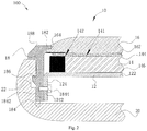
Fig. 2 illustrates a sectional view of the electronic device taken along line A-A and/or line B-B inFig. 1 . -
Fig. 3 illustrates a flow chart of a manufacturing method of a display screen assembly according to an embodiment of the present disclosure. - Embodiments of the present disclosure will be described in detail and examples of the embodiments will be illustrated in the drawings, where same or similar reference numerals are used to indicate same or similar members or members with same or similar functions. The embodiments described herein with reference to drawings are explanatory, illustrative, and used to generally understand the present disclosure. The embodiments shall not be construed to limit the present disclosure.
- In the specification, it is to be understood that terms such as "central", "longitudinal", "lateral", "length", "width", "thickness", "upper", "lower", "front", "rear", "left", "right", "vertical", "horizontal", "top", "bottom", "inner", "outer", "clockwise" and "counterclockwise" should be construed to refer to the orientation as then described or as shown in the drawings under discussion. These relative terms are for convenience of description and do not require that the present disclosure be constructed or operated in a particular orientation. In addition, terms such as "first" and "second" are used herein for purposes of description and are not intended to indicate or imply relative importance or significance. Thus, features limited by "first" and "second" are intended to indicate or imply including one or more than one these features. In the description of the present disclosure, "a plurality of" means two or more than two, unless specified otherwise.
- In the present disclosure, unless specified or limited otherwise, the terms "mounted", "connected", "coupled", "fixed" and the like are used broadly, and can be, for example, fixed connections, detachable connections, or integral connections; can also be mechanical or electrical connections; can also be direct connections or indirect connections via intervening structures; can also be inner communications of two elements. The above terms can be understood by those skilled in the art according to specific situations.
- In the description of the present disclosure, a structure in which a first feature is "on" a second feature can include an embodiment in which the first feature directly contacts the second feature, and can also include an embodiment in which an additional feature is formed between the first feature and the second feature, so that the first feature does not directly contact the second feature, unless otherwise specified. Furthermore, a first feature "on", "above" or "on top of' a second feature can include an embodiment in which the first feature is right "on", "above" or "on top of" the second feature, and can also include an embodiment in which the first feature is not right "on", "above" or "on top of" the second feature, or just means that the first feature has a sea level elevation larger than the sea level elevation of the second feature. While first feature "beneath", "below" or "on bottom of" a second feature can include an embodiment in which the first feature is right "beneath", "below" or "on bottom of" the second feature, and can also include an embodiment in which the first feature is not right "beneath", "below" or "on bottom of" the second feature, or just means that the first feature has a sea level elevation smaller than the sea level elevation of the second feature.
- The following disclosure provides many different embodiments or examples to realize different structures of the present disclosure. To simplify the disclosure of the present disclosure, components and configurations in particular examples are elaborated. Of course, they are illustrative, and are not intended to limit the present disclosure. Moreover, reference numbers and/or letters can be repeated in different examples of the present disclosure for the purpose of simplicity and clarity, which shall not be constructed to indicate the relationships among various embodiments and/or configurations. In addition, the present disclosure provides examples of various specific processes and materials, but applicability of other processes and/or utilization of other materials are conceivable for those skilled in the art.
- As illustrated in
Figs. 1 andFig. 2 , anelectronic device 100 according to embodiments of the present disclosure includes adisplay screen assembly 10, and arear cover 20. Theelectronic device 100 can be a mobile phone, a tablet computer, a smart watch or the like. - In some embodiments, the
display screen assembly 10 is configured to display images, texts and so on. Moreover, thedisplay screen assembly 10 can also be configured to receive a touch operation of a user. Thedisplay screen assembly 10 includes abracket 12, adisplay screen 14, acover plate 16 and adecoration enclosure 18. - The
bracket 12 includes abottom wall 122 and aside wall 124 bending from thebottom wall 122. In embodiments of the present disclosure, thebottom wall 122 and theside wall 124 are perpendicular to each other, and fourside walls 124 are provided, in other words, theside walls 124 extend from four sides of thebottom wall 122 respectively. In other embodiments, thebottom wall 122 may not be perpendicular to theside wall 124. Thebracket 12 can be made of metal materials, such as steel, aluminum alloy, or magnesium alloy. Thebracket 12 can also be made of nonmetal materials, such as acrylonitrile-butadiene-styrene copolymer (ABS), polyvinyl chloride (PVC) or polycarbonate (PC). The material of thebracket 12 is not limited to the materials mentioned above, and an appropriate material can be selected according to requirements in a practical application. - The
display screen 14 includes atop surface 144 and abottom surface 146. Thebottom surface 146 of thedisplay screen 14 is provided on thebottom wall 122 of thebracket 12, and thebottom surface 146 of thedisplay screen 14 can be joined to thebottom wall 122 in an adhering manner. In some embodiments of the present disclosure, a layer of foam adhesive or double sided adhesive can be padded between thebottom surface 146 of thedisplay screen 14 and thebottom wall 122 of thebracket 12 according to requirements. In some embodiments of the present disclosure, a gap can be retained between thebottom surface 146 of thedisplay screen 14 and thebottom wall 122 of thebracket 12 to provide a buffering space so as to protect thedisplay screen 14 when encountering a collision. Thedisplay screen 14 and theside wall 124 are located at two opposite sides of thebottom wall 122 respectively. Thedisplay screen 14 can be configured as a liquid crystal display (LCD), an organic light-emitting diode (OLED) display screen or a flexible OLED display screen. Thedisplay screen 14 includes adisplay area 141 and anon-display area 142, and thedisplay area 141 is configured to achieve a function of thedisplay screen assembly 10 for displaying images, texts and the like. - The
cover plate 16 is provided on thedisplay screen 14. Thebottom surface 162 of thecover plate 16 and thetop surface 144 of thedisplay screen 14 can be joined in a full lamination manner. In some embodiments of the present disclosure, thebottom surface 162 of thecover plate 16 and thetop surface 144 of thedisplay screen 16 can be laminated by means of an optically clear adhesive (OCA). Thecover plate 16 is configured as a touch-screen cover plate. In other words, a touch control circuit of a touch screen is integrated in thecover plate 16, and a touch control function can be achieved by clicking thecover plate 16. Thecover plate 16 can be made of materials such as glass, sapphire, or polyvinyl chloride (PVC), etc. In some embodiments, thecover plate 16 is configured to have two layers of structures, namely a touch panel and a protection cover sheet provided on the touch panel. The touch panel includes the touch control circuit of the touch screen and is configured to achieve the touch operation of thedisplay screen assembly 10, and the protection cover sheet is configured to protect the touch panel from being damaged due to direct touch operations on the touch panel. In other words, thecover plate 16 serves as the touch screen with better protection thereof. Thecover plate 16 has agroove 164 at a side wall thereof. In some embodiments of the present disclosure, thegroove 164 is configured to have a stepped shape. In other embodiments, thegroove 164 can also be configured to have a recessed shape. The shape of thegroove 164 is not limited herein. Thebottom surface 162 of thecover plate 16 is screen-printed with a circle of black-ink edge at a periphery thereof, so as to shield thenon-display area 142 and other internal structures. - The
decoration enclosure 18 includes a first joiningpart 182 and a second joiningpart 184 coupled to each other. The first joiningpart 182 is received in thegroove 164. In some embodiments of the present disclosure, the first joiningpart 182 is snapped in thegroove 164, and thedecoration enclosure 18 is joined with thecover plate 16 as a whole by in-mold injection molding. In some embodiments of the present disclosure, the first joiningpart 182 is configured to have a stepped shape matched the shape of thegroove 164. In other embodiments, the first joiningpart 182 can also be configured to have another shape matched the shape of thegroove 164, as long as the first joiningpart 182 can be fitted with and coupled to thegroove 164. The second joiningpart 184 is joined with theside wall 124. In embodiments of the present disclosure, the second joiningpart 184 has a threadedhole 1842 at an inner side thereof, theside wall 124 has a coupling through-hole 1242 at a position corresponding to the threadedhole 1842, the coupling through-hole 1242 is threaded and the second joiningpart 184 is joined to theside wall 124 through ascrew 1844. In some embodiments of the present disclosure, thescrew 1844 passes through the coupling through-hole 1242 and is screwed into the threadedhole 1842 of the second joiningpart 184 so as to fasten the second joiningpart 184 with theside wall 124. In other embodiments, the second joiningpart 184 can be joined with theside wall 124 by one or a combination of several ones of adhering, screwing, snapping and welding. In some embodiments, the second joiningpart 184 can be joined with theside wall 124 by selecting an appropriate coupling manner according to practical requirements. The coupling manner between the second joiningpart 184 and theside wall 124 is not limited herein. Anouter wall 188 of thedecoration enclosure 18 is configured to have an arc shape. In other embodiments, theouter wall 188 of thedecoration enclosure 18 is not limited to having the arc shape, but can also be configured to have other shapes. In some embodiments of the present disclosure, thedecoration enclosure 18 surrounds a periphery of thecover plate 16. - The
rear cover 20 is snapped with thedecoration enclosure 18. In some embodiments of the present disclosure, thedecoration enclosure 18 is provided with aboss 186 at a side of thedecoration enclosure 18 opposite to the threadedhole 1842, therear cover 20 has agroove 22 corresponding to theboss 186, and theboss 186 is snapped into thegroove 22 to couple therear cover 20 with thedecoration enclosure 18. - During assembling the
display screen assembly 10 according to embodiments of the present disclosure, first, thedecoration enclosure 18 is joined with thecover plate 16 as a whole by in-mold injection molding, and the first joiningpart 182 is received in thegroove 164. Then, thebottom surface 162 of thecover plate 16 is fully laminated with thetop surface 144 of thedisplay screen 16 through the optically clear adhesive (OCA), so that thedecoration enclosure 18, thecover plate 16 and thetop surface 144 of thedisplay screen 14 are coupled together. Finally, thebracket 12 is joined with thedecoration enclosure 18, theside wall 124 of thebracket 12 is secured to the second joiningpart 184 of thedecoration enclosure 18, and thebottom surface 146 of thedisplay screen 14 is provided on thebottom wall 122 of thebracket 12. Thus, thedisplay screen assembly 10 is formed. - In the
display screen assembly 10 and theelectronic device 100 according to embodiments of the present disclosure, since structures of thebracket 12, thedisplay screen 14, thecover plate 16 and thedecoration enclosure 18 of thedisplay screen assembly 10 are designed reasonably, it is possible to assemble thedisplay screen 14 and thecover plate 16 in the electronic device when a peripheral bezel of theelectronic device 100 is extremely narrow, thereby solving a problem of assembling difficulties resulted from the extremely narrow bezel of theelectronic device 100. Thus, the extremely narrow bezel is achieved, a screen-to-body ratio is increased, and hence user experience is improved. Thedisplay screen assembly 10 and theelectronic device 100 according to embodiments of the present disclosure have a simple structure and an easy assembling process, which facilitates improving the production efficiency and saving the production cost. - Further, the
decoration enclosure 18 is coupled with thecover plate 16 as a whole by in-mold injection molding, and the first joiningpart 182 is received in thegroove 164. This molding manner allows thedecoration enclosure 18 to be fitted with thecover plate 16 better, and thegroove 164 having the stepped shape allows thedecoration enclosure 18 to fix thecover plate 16 in theelectronic device 100 more stably. Moreover, the first joiningpart 182 is received in thegroove 164 having the stepped shape, so that the first joiningpart 182 covers part of the black-ink edge of thecover plate 16, thereby reducing a width of the black-ink edge. When the user uses theelectronic device 100, the black-ink edge seen by the user is narrower and more artistic, thus improving the user experience. - As illustrated in
Figs. 2 and3 , a manufacturing method according to embodiments of the present disclosure is configured to manufacture adisplay screen assembly 10. The manufacturing method includes actions at following blocks. - At block S11: a
decoration enclosure 18, acover plate 16, adisplay screen 14 and abracket 12 are provided. - At block S12: the
decoration enclosure 18 and thecover plate 16 are in-mold injection-molded to couple thedecoration enclosure 18 to thecover plate 16 fixedly, in which thecover plate 16 has agroove 164 at a side wall thereof, thedecoration enclosure 18 includes a first joiningpart 182 and a second joiningpart 184 coupled to each other, and the first joiningpart 182 is received in thegroove 164. - At block S 13: a
top surface 144 of thedisplay screen 14 is fully laminated with abottom surface 162 of thecover plate 16. - At block S14: a
side wall 124 of thebracket 12 is coupled to thedecoration enclosure 18 fixedly, and abottom wall 122 of thebracket 12 is arranged under thedisplay screen 14. - The
bracket 12 includes thebottom wall 122 and aside wall 124 bending from thebottom wall 122. In embodiments of the present disclosure, thebottom wall 122 and theside wall 124 are perpendicular to each other, and fourside walls 124 are provided, in other words, theside walls 124 extend from four sides of thebottom wall 122 respectively. In other embodiments, thebottom wall 122 may not be perpendicular to theside wall 124. Thebracket 12 can be made of metal materials, such as steel, aluminum alloy, and magnesium alloy. Thebracket 12 can also be made of nonmetal materials, such as acrylonitrile-butadiene-styrene copolymer (ABS), polyvinyl chloride (PVC), or polycarbonate (PC). The material of thebracket 12 is not limited to the materials mentioned above, and an appropriate material can be selected according to requirements in a practical application. - The
display screen 14 includes thetop surface 144 and abottom surface 146. Thebottom surface 146 of thedisplay screen 14 is provided on thebottom wall 122 of thebracket 12, and thebottom surface 146 of thedisplay screen 14 can be joined to thebottom wall 122 in an adhering manner. In some embodiments of the present disclosure, a layer of foam adhesive or double sided adhesive can be padded between thebottom surface 146 of thedisplay screen 14 and thebottom wall 122 of thebracket 12 according to requirements. In some embodiments of the present disclosure, a gap can also be retained between thebottom surface 146 of thedisplay screen 14 and thebottom wall 122 of thebracket 12 to provide a buffering space so as to protect thedisplay screen 14 when encountering a collision. Thedisplay screen 14 and theside wall 124 are located at two opposite sides of thebottom wall 122 respectively. Thedisplay screen 14 can be configured as a liquid crystal display (LCD), an organic light-emitting diode (OLED) display screen or a flexible OLED display screen. Thedisplay screen 14 includes adisplay area 141 and anon-display area 142, and thedisplay area 141 is configured to achieve a function of thedisplay screen assembly 10 for displaying images, texts and the like. - The
cover plate 16 is provided on thedisplay screen 14. Thebottom surface 162 of thecover plate 16 and thetop surface 144 of thedisplay screen 14 can be laminated by means of an optically clear adhesive (OCA). Thecover plate 16 is configured as a touch-screen cover plate. In other words, a touch control circuit of a touch screen is integrated in thecover plate 16, and a touch control function can be achieved by clicking thecover plate 16. Thecover plate 16 can be made of materials such as glass, sapphire, or polyvinyl chloride (PVC), etc. In some embodiments, thecover plate 16 is configured to have two layers of structures, namely a touch panel and a protection cover sheet provided on the touch panel. The touch panel is configured to achieve the touch operation of thedisplay screen assembly 10, and the protection cover sheet is configured to protect the touch panel from being damaged due to direct touch operations on the touch panel. Thecover plate 16 has agroove 164 at a side wall thereof. In some embodiments of the present disclosure, thegroove 164 is configured to have a stepped shape. In other embodiments, thegroove 164 can also be configured to have a recessed shape. The shape of thegroove 164 is not limited herein. Thebottom surface 162 of thecover plate 16 is screen-printed with a circle of black-ink edge at a periphery thereof, so as to shield thenon-display area 142 and other internal structures. - The
decoration enclosure 18 includes the first joiningpart 182 and the second joiningpart 184 coupled to each other. The first joiningpart 182 is received in thegroove 164. In at least one embodiment, the first joiningpart 182 is snapped in thegroove 164. In some embodiments of the present disclosure, the first joiningpart 182 is configured to have a stepped shape matched the shape of thegroove 164. In other embodiments, the first joiningpart 182 can also be configured have another shape matched the shape of thegroove 164, as long as the first joiningpart 182 can be fitted with and coupled to thegroove 164. The second joiningpart 184 is joined with theside wall 124. In embodiments of the present disclosure, the second joiningpart 184 has a threadedhole 1842 at an inner side thereof, theside wall 124 has a coupling through-hole 1242 at a position corresponding to the threadedhole 1842, the coupling through-hole 1242 is threaded and the second joiningpart 184 is coupled to theside wall 124 through ascrew 1844. In some embodiments of the present disclosure, thescrew 1844 passes through the coupling through-hole 1242 and is screwed into the threadedhole 1842 of the second joiningpart 184 so as to fasten the second joiningpart 184 with theside wall 124. In other embodiments, the second joiningpart 184 can be joined with theside wall 124 by one or a combination of several ones of adhering, screwing, snapping and welding. In some embodiments, the second joiningpart 184 can be joined with theside wall 124 by selecting an appropriate coupling manner according to practical requirements. The coupling manner between the second joiningpart 184 and theside wall 124 is not limited herein. Anouter wall 188 of thedecoration enclosure 18 is configured to have an arc shape. In other embodiments, theouter wall 188 of thedecoration enclosure 18 is not limited to having the arc shape, but can also be configured to have other shapes. In some embodiments of the present disclosure, thedecoration enclosure 18 surrounds a periphery of thecover plate 16. - In the
display screen assembly 10 manufactured by the manufacturing method according to embodiments of the present disclosure, since structures of thebracket 12, thedisplay screen 14, thecover plate 16 and thedecoration enclosure 18 of thedisplay screen assembly 10 are designed reasonably, it is possible to assemble thedisplay screen 14 and thecover plate 16 in theelectronic device 100 when a peripheral bezel of theelectronic device 100 is extremely narrow, thereby solving a problem of assembling difficulties resulted from the extremely narrow bezel of theelectronic device 100. Thus, the extremely narrow bezel is achieved, a screen-to-body ratio is increased, and hence the user experience is improved. Thedisplay screen assembly 10 and theelectronic device 100 according to embodiments of the present disclosure have a simple structure and an easy assembling process, which facilitates improving the production efficiency and saving the production cost. - Further, the
decoration enclosure 18 is joined with thecover plate 16 as a whole by in-mold injection molding, and the first joiningpart 182 is received in thegroove 164. This molding manner allows thedecoration enclosure 18 to be fitted withcover plate 16 better, and thegroove 164 having the stepped shape allows thedecoration enclosure 18 to fix thecover plate 16 in theelectronic device 100 more stably. Moreover, the first joiningpart 182 is received in thegroove 164 having the stepped shape, so that the first joiningpart 182 covers part of the black-ink edge of thecover plate 16, thereby reducing a width of the black-ink edge. When the user uses theelectronic device 100, the black-ink edge seen by the user is narrower and more artistic, thus improving the user experience. - Reference throughout this specification to "an embodiment", "some embodiments", "an illustrative embodiment", "an example", "a specific example" or "some examples" means that a particular feature, structure, material, or characteristic described in connection with the embodiment or example is included in at least one embodiment or example of the present disclosure. Thus, the appearances of the phrases in various places throughout this specification are not necessarily referring to the same embodiment or example of the present disclosure. Furthermore, the particular features, structures, materials, or characteristics can be combined in any suitable manner in one or more embodiments or examples.
- In addition, terms such as "first" and "second" are used herein for purposes of description and are not intended to indicate or imply relative importance or significance. Thus, the feature defined with "first" and "second" can comprise one or more of this feature. In the description of the present disclosure, "a plurality of" means two or more than two, unless specified otherwise.
- Although explanatory embodiments have been shown and described, it would be appreciated by those skilled in the art that the above embodiments cannot be construed to limit the present disclosure, and changes, alternatives, and modifications can be made in the embodiments without departing from principles and scope of the present disclosure. The scope of the present disclosure is limited by the claims and its equivalence.
Claims (15)
- A display screen assembly (10), comprising:a bracket (12) having a bottom wall (122) and a side wall (124) bending from the bottom wall (122);a display screen (14) having a top surface (144) and a bottom surface (146), the bottom surface (146) of the display screen (14) being provided on the bottom wall (122) of the bracket (12), and the display screen (14) and the side wall (124) of the bracket (12) being arranged at two opposite sides of the bottom wall (122) of the bracket (12) respectively;a cover plate (16) having a bottom surface (162) joined with the top surface (144) of the display screen (14), and the cover plate (16) having a groove (164) at a side wall thereof; anda decoration enclosure (18) comprising a first joining part (182) and a second joining part (184) coupled to each other, the first joining part (182) being received in the groove (164), and the second joining part (184) being joined to the side wall (124) of the bracket (12).
- The display screen assembly (10) according to claim 1, wherein the second joining part (184) is joined with the side wall (124) of the bracket (12) by one or a combination of ones of adhering, screwing, snapping and welding.
- The display screen assembly (10) according to any one of claims 1 or 2, wherein the bottom surface (162) of the cover plate (16) is screen-printed with a black-ink edge, the top surface (144) of the display screen (14) defines a non-display area (142), and the black-ink edge shields the non-display area (142).
- The display screen assembly (10) according to any one of claims 1 to 3, wherein the decoration enclosure (18) is joined with the cover plate (16) by means of in-mold injection molding.
- The display screen assembly (10) according to any one of claims 1 to 4, wherein the top surface (144) of the display screen (14) is joined with the bottom surface (162) of the cover plate (16) in a full lamination manner.
- The display screen assembly (10) according to any one of claims 1 to 4, wherein the top surface (144) of the display screen (14) is laminated with the bottom surface (162) of the cover plate (16) through an optically clear adhesive (OCA).
- The display screen assembly (10) according to any one of claims 1 to 6, wherein the bottom surface (146) of the display screen (14) is joined with the bottom wall (122) of the bracket (12) in an adhering manner.
- The display screen assembly (10) according to any one of claims 1 to 7, wherein the cover plate (16) is configured as a touch-screen cover plate.
- The display screen assembly (10) according to any one of claims 1 to 8, wherein an outer surface of the decoration enclosure (18) is configured as an arc surface.
- An electronic device (100), comprising a display screen assembly (10) according to any one of claims 1 to 9 and a rear cover (20) coupled to the display screen assembly (10).
- The electronic device (100) according to claim 10, wherein the rear cover (20) is snapped with the decoration enclosure (18).
- The electronic device (100) according to one of claims 10 or 11, wherein the decoration enclosure (18) is provided with a boss (186) at a side thereof, the rear cover (20) has a groove (22) corresponding to the boss (186), and the boss (186) is configured to be snapped into the groove (22) of the rear cover (20) to couple the rear cover (20) with the decoration enclosure (18).
- A manufacturing method for manufacturing a display screen assembly, comprising:providing a decoration enclosure, a cover plate, a display screen and a bracket;in-mold injection-molding the decoration enclosure and the cover plate to couple the decoration enclosure to the cover plate fixedly, the cover plate having a groove at a side wall thereof, the decoration enclosure comprising a first joining part and a second joining part coupled to each other, and the first joining part being received in the groove;laminating a top surface of the display screen with a bottom surface of the cover plate fully; andcoupling a side wall of the bracket to the decoration enclosure fixedly, and arranging a bottom wall of the bracket under the display screen.
- The manufacturing method according to claim 13, wherein the top surface of the display screen is laminated with the bottom surface of the cover plate through an optically clear adhesive (OCA).
- The manufacturing method according to one of claims 13 or 14, wherein the side wall of the bracket is joined with the decoration enclosure by one or a combination of ones of adhering, screwing, snapping and welding.
Priority Applications (1)
| Application Number | Priority Date | Filing Date | Title |
|---|---|---|---|
| EP18211850.5A EP3487157B1 (en) | 2017-01-09 | 2017-08-23 | Electronic device |
Applications Claiming Priority (2)
| Application Number | Priority Date | Filing Date | Title |
|---|---|---|---|
| CN201720024309.3U CN206363698U (en) | 2017-01-09 | 2017-01-09 | Display screen component and electronic installation |
| CN201710013734.7A CN106847091B (en) | 2017-01-09 | 2017-01-09 | Display screen assembly, manufacturing method thereof and electronic device |
Related Child Applications (2)
| Application Number | Title | Priority Date | Filing Date |
|---|---|---|---|
| EP18211850.5A Division EP3487157B1 (en) | 2017-01-09 | 2017-08-23 | Electronic device |
| EP18211850.5A Division-Into EP3487157B1 (en) | 2017-01-09 | 2017-08-23 | Electronic device |
Publications (2)
| Publication Number | Publication Date |
|---|---|
| EP3346675A1 true EP3346675A1 (en) | 2018-07-11 |
| EP3346675B1 EP3346675B1 (en) | 2019-03-27 |
Family
ID=59745719
Family Applications (2)
| Application Number | Title | Priority Date | Filing Date |
|---|---|---|---|
| EP17187504.0A Not-in-force EP3346675B1 (en) | 2017-01-09 | 2017-08-23 | Display screen assembly, manufacturing method thereof and electronic device |
| EP18211850.5A Active EP3487157B1 (en) | 2017-01-09 | 2017-08-23 | Electronic device |
Family Applications After (1)
| Application Number | Title | Priority Date | Filing Date |
|---|---|---|---|
| EP18211850.5A Active EP3487157B1 (en) | 2017-01-09 | 2017-08-23 | Electronic device |
Country Status (6)
| Country | Link |
|---|---|
| US (2) | US10534462B2 (en) |
| EP (2) | EP3346675B1 (en) |
| JP (1) | JP6812557B2 (en) |
| KR (1) | KR102182617B1 (en) |
| ES (1) | ES2729806T3 (en) |
| WO (1) | WO2018126708A1 (en) |
Families Citing this family (14)
| Publication number | Priority date | Publication date | Assignee | Title |
|---|---|---|---|---|
| USD828828S1 (en) * | 2015-10-02 | 2018-09-18 | Samsung Electronics Co., Ltd. | Electronic device |
| ES2729806T3 (en) * | 2017-01-09 | 2019-11-06 | Guangdong Oppo Mobile Telecommunications Corp Ltd | Display screen assembly, manufacturing method and electronic device |
| CH713623A1 (en) * | 2017-03-27 | 2018-09-28 | Fgp Capital Sa | Device for reading an ice machine or screen. |
| KR102392246B1 (en) * | 2017-11-13 | 2022-04-29 | 삼성전자주식회사 | Electronic device with waterproofing structure |
| JP7132741B2 (en) * | 2018-04-25 | 2022-09-07 | フォルシアクラリオン・エレクトロニクス株式会社 | equipment housing |
| CN108873675B (en) * | 2018-08-03 | 2024-07-05 | 华为技术有限公司 | Waterproof smart watch |
| KR102504397B1 (en) * | 2018-08-20 | 2023-03-02 | 삼성디스플레이 주식회사 | Display device and method for fabricating electronic device using the same |
| KR102652773B1 (en) * | 2018-12-13 | 2024-04-03 | 삼성디스플레이 주식회사 | Release film for window and method of manufacturing the same |
| DE102020205864A1 (en) | 2020-05-11 | 2021-11-11 | BSH Hausgeräte GmbH | Display and operating device and household appliance |
| KR102869590B1 (en) * | 2021-01-08 | 2025-10-14 | 삼성전자주식회사 | Electronic apparatus having ink layer printed for forming opening on glass substrate covering display panel |
| US12298544B2 (en) | 2021-01-08 | 2025-05-13 | Samsung Electronics Co., Ltd. | Electronic apparatus having ink layer printed for forming opening on glass substrate covering display panel |
| US12418997B2 (en) * | 2022-05-12 | 2025-09-16 | Chengdu Boe Optoelectronics Technology Co., Ltd. | Display device |
| CN115376414B (en) * | 2022-08-31 | 2023-11-21 | 京东方科技集团股份有限公司 | Display module and display device |
| DE102022209679A1 (en) * | 2022-09-15 | 2024-03-21 | Robert Bosch Gesellschaft mit beschränkter Haftung | Display device |
Citations (3)
| Publication number | Priority date | Publication date | Assignee | Title |
|---|---|---|---|---|
| US20140239781A1 (en) * | 2013-02-25 | 2014-08-28 | Motorola Mobility Llc | Electronic Device Having a Display and Method of Manufacture |
| US20160227654A1 (en) * | 2015-02-02 | 2016-08-04 | Samsung Display Co., Ltd. | Display device |
| WO2016169393A1 (en) * | 2015-04-20 | 2016-10-27 | 广东欧珀移动通信有限公司 | Display screen assembly and terminal |
Family Cites Families (21)
| Publication number | Priority date | Publication date | Assignee | Title |
|---|---|---|---|---|
| US6400571B1 (en) * | 1998-10-21 | 2002-06-04 | Furukawa Electric Co., Ltd. | Electronic equipment housing |
| JP2012078385A (en) * | 2010-09-30 | 2012-04-19 | Casio Comput Co Ltd | Method for manufacturing electronic member integrated with protection plate, and electronic member integrated with protection plate |
| KR101809615B1 (en) * | 2010-10-28 | 2017-12-15 | 엘지전자 주식회사 | Display Apparatus |
| WO2013118164A1 (en) | 2012-02-06 | 2013-08-15 | パナソニック株式会社 | Mobile terminal device |
| CN202872874U (en) | 2012-11-06 | 2013-04-10 | 广东欧珀移动通信有限公司 | A touch screen decorative ring structure |
| US9716307B2 (en) * | 2012-11-08 | 2017-07-25 | Htc Corporation | Mobile device and antenna structure |
| KR102025706B1 (en) * | 2013-01-30 | 2019-09-26 | 삼성전자주식회사 | Antenna device for portable terminal |
| US9658479B2 (en) * | 2013-01-31 | 2017-05-23 | Apple Inc. | Electronic device with display backlight unit and display assembly |
| CN103116229B (en) * | 2013-02-04 | 2015-08-12 | 小米科技有限责任公司 | A kind of containment vessel and liquid crystal display terminal |
| CN104010458B (en) | 2013-02-25 | 2017-09-08 | 谷歌技术控股有限责任公司 | Electronic installation and manufacture method with display |
| FR3021134B1 (en) * | 2014-05-14 | 2023-01-06 | Lg Electronics Inc | MOBILE TERMINAL |
| CN104503540A (en) | 2014-12-19 | 2015-04-08 | 广东欧珀移动通信有限公司 | Electronic equipment |
| CN204406408U (en) | 2014-12-27 | 2015-06-17 | 广东欧珀移动通信有限公司 | A kind of display module and portable electron device |
| EP3537694B1 (en) * | 2015-02-06 | 2023-08-02 | Samsung Electronics Co., Ltd. | Electronic device including display with bent area |
| CN104866017A (en) * | 2015-04-20 | 2015-08-26 | 广东欧珀移动通信有限公司 | Terminal front cover and terminal |
| KR102149780B1 (en) * | 2015-07-03 | 2020-08-31 | 엘지전자 주식회사 | Mobile terminal |
| CN105158951B (en) * | 2015-09-22 | 2019-01-25 | 北京京东方多媒体科技有限公司 | a display device |
| ES2729806T3 (en) * | 2017-01-09 | 2019-11-06 | Guangdong Oppo Mobile Telecommunications Corp Ltd | Display screen assembly, manufacturing method and electronic device |
| CN206363698U (en) * | 2017-01-09 | 2017-07-28 | 广东欧珀移动通信有限公司 | Display screen component and electronic installation |
| CN106847091B (en) * | 2017-01-09 | 2019-05-03 | Oppo广东移动通信有限公司 | Display screen assembly, manufacturing method thereof and electronic device |
| EP3346355B1 (en) * | 2017-01-09 | 2020-06-10 | Guangdong Oppo Mobile Telecommunications Corp., Ltd. | Display screen assembly, assembling method thereof and electronic device |
-
2017
- 2017-08-23 ES ES17187504T patent/ES2729806T3/en active Active
- 2017-08-23 EP EP17187504.0A patent/EP3346675B1/en not_active Not-in-force
- 2017-08-23 EP EP18211850.5A patent/EP3487157B1/en active Active
- 2017-08-25 JP JP2019534788A patent/JP6812557B2/en not_active Expired - Fee Related
- 2017-08-25 KR KR1020197017441A patent/KR102182617B1/en not_active Expired - Fee Related
- 2017-08-25 WO PCT/CN2017/098973 patent/WO2018126708A1/en not_active Ceased
- 2017-08-28 US US15/688,666 patent/US10534462B2/en active Active
-
2019
- 2019-06-12 US US16/439,355 patent/US10521040B2/en active Active
Patent Citations (3)
| Publication number | Priority date | Publication date | Assignee | Title |
|---|---|---|---|---|
| US20140239781A1 (en) * | 2013-02-25 | 2014-08-28 | Motorola Mobility Llc | Electronic Device Having a Display and Method of Manufacture |
| US20160227654A1 (en) * | 2015-02-02 | 2016-08-04 | Samsung Display Co., Ltd. | Display device |
| WO2016169393A1 (en) * | 2015-04-20 | 2016-10-27 | 广东欧珀移动通信有限公司 | Display screen assembly and terminal |
Also Published As
| Publication number | Publication date |
|---|---|
| JP6812557B2 (en) | 2021-01-13 |
| WO2018126708A1 (en) | 2018-07-12 |
| US10521040B2 (en) | 2019-12-31 |
| US20180196559A1 (en) | 2018-07-12 |
| US20190294286A1 (en) | 2019-09-26 |
| EP3487157B1 (en) | 2020-01-29 |
| ES2729806T3 (en) | 2019-11-06 |
| EP3346675B1 (en) | 2019-03-27 |
| EP3487157A1 (en) | 2019-05-22 |
| KR20190078651A (en) | 2019-07-04 |
| JP2020506412A (en) | 2020-02-27 |
| KR102182617B1 (en) | 2020-11-25 |
| US10534462B2 (en) | 2020-01-14 |
Similar Documents
| Publication | Publication Date | Title |
|---|---|---|
| US10521040B2 (en) | Display screen assembly, manufacturing method thereof and electronic device | |
| US10440839B2 (en) | Display screen assembly, assembling method thereof and electronic device | |
| US10564749B2 (en) | Display screen assembly, assembling method thereof and electronic device | |
| US10248233B2 (en) | Display screen assembly, method for assembling display screen assembly and electronic device | |
| CN106847091B (en) | Display screen assembly, manufacturing method thereof and electronic device | |
| CN106843574B (en) | Display screen component and its manufacturing method and electronic device | |
| US10503204B2 (en) | Display screen assembly, method for assembling display screen assembly and electronic device | |
| CN206363698U (en) | Display screen component and electronic installation | |
| US10412843B2 (en) | Display panel assembly and manufacturing method thereof | |
| US10405439B2 (en) | Display panel assembly and manufacturing method thereof | |
| CN206517453U (en) | Display screen component and electronic installation |
Legal Events
| Date | Code | Title | Description |
|---|---|---|---|
| PUAI | Public reference made under article 153(3) epc to a published international application that has entered the european phase |
Free format text: ORIGINAL CODE: 0009012 |
|
| STAA | Information on the status of an ep patent application or granted ep patent |
Free format text: STATUS: REQUEST FOR EXAMINATION WAS MADE |
|
| 17P | Request for examination filed |
Effective date: 20180516 |
|
| AK | Designated contracting states |
Kind code of ref document: A1 Designated state(s): AL AT BE BG CH CY CZ DE DK EE ES FI FR GB GR HR HU IE IS IT LI LT LU LV MC MK MT NL NO PL PT RO RS SE SI SK SM TR |
|
| AX | Request for extension of the european patent |
Extension state: BA ME |
|
| RIC1 | Information provided on ipc code assigned before grant |
Ipc: B22D 19/04 20060101ALI20180824BHEP Ipc: G06F 3/041 20060101ALI20180824BHEP Ipc: G06F 1/16 20060101ALI20180824BHEP Ipc: H04M 1/02 20060101AFI20180824BHEP Ipc: B29C 45/14 20060101ALN20180824BHEP Ipc: G02F 1/1333 20060101ALI20180824BHEP |
|
| GRAP | Despatch of communication of intention to grant a patent |
Free format text: ORIGINAL CODE: EPIDOSNIGR1 |
|
| STAA | Information on the status of an ep patent application or granted ep patent |
Free format text: STATUS: GRANT OF PATENT IS INTENDED |
|
| INTG | Intention to grant announced |
Effective date: 20181009 |
|
| GRAS | Grant fee paid |
Free format text: ORIGINAL CODE: EPIDOSNIGR3 |
|
| GRAA | (expected) grant |
Free format text: ORIGINAL CODE: 0009210 |
|
| STAA | Information on the status of an ep patent application or granted ep patent |
Free format text: STATUS: THE PATENT HAS BEEN GRANTED |
|
| AK | Designated contracting states |
Kind code of ref document: B1 Designated state(s): AL AT BE BG CH CY CZ DE DK EE ES FI FR GB GR HR HU IE IS IT LI LT LU LV MC MK MT NL NO PL PT RO RS SE SI SK SM TR |
|
| REG | Reference to a national code |
Ref country code: GB Ref legal event code: FG4D |
|
| REG | Reference to a national code |
Ref country code: CH Ref legal event code: EP |
|
| REG | Reference to a national code |
Ref country code: AT Ref legal event code: REF Ref document number: 1114381 Country of ref document: AT Kind code of ref document: T Effective date: 20190415 |
|
| REG | Reference to a national code |
Ref country code: IE Ref legal event code: FG4D |
|
| REG | Reference to a national code |
Ref country code: DE Ref legal event code: R096 Ref document number: 602017002939 Country of ref document: DE |
|
| REG | Reference to a national code |
Ref country code: NL Ref legal event code: FP |
|
| PG25 | Lapsed in a contracting state [announced via postgrant information from national office to epo] |
Ref country code: NO Free format text: LAPSE BECAUSE OF FAILURE TO SUBMIT A TRANSLATION OF THE DESCRIPTION OR TO PAY THE FEE WITHIN THE PRESCRIBED TIME-LIMIT Effective date: 20190627 Ref country code: FI Free format text: LAPSE BECAUSE OF FAILURE TO SUBMIT A TRANSLATION OF THE DESCRIPTION OR TO PAY THE FEE WITHIN THE PRESCRIBED TIME-LIMIT Effective date: 20190327 Ref country code: SE Free format text: LAPSE BECAUSE OF FAILURE TO SUBMIT A TRANSLATION OF THE DESCRIPTION OR TO PAY THE FEE WITHIN THE PRESCRIBED TIME-LIMIT Effective date: 20190327 Ref country code: LT Free format text: LAPSE BECAUSE OF FAILURE TO SUBMIT A TRANSLATION OF THE DESCRIPTION OR TO PAY THE FEE WITHIN THE PRESCRIBED TIME-LIMIT Effective date: 20190327 |
|
| PG25 | Lapsed in a contracting state [announced via postgrant information from national office to epo] |
Ref country code: BG Free format text: LAPSE BECAUSE OF FAILURE TO SUBMIT A TRANSLATION OF THE DESCRIPTION OR TO PAY THE FEE WITHIN THE PRESCRIBED TIME-LIMIT Effective date: 20190627 Ref country code: GR Free format text: LAPSE BECAUSE OF FAILURE TO SUBMIT A TRANSLATION OF THE DESCRIPTION OR TO PAY THE FEE WITHIN THE PRESCRIBED TIME-LIMIT Effective date: 20190628 Ref country code: RS Free format text: LAPSE BECAUSE OF FAILURE TO SUBMIT A TRANSLATION OF THE DESCRIPTION OR TO PAY THE FEE WITHIN THE PRESCRIBED TIME-LIMIT Effective date: 20190327 Ref country code: LV Free format text: LAPSE BECAUSE OF FAILURE TO SUBMIT A TRANSLATION OF THE DESCRIPTION OR TO PAY THE FEE WITHIN THE PRESCRIBED TIME-LIMIT Effective date: 20190327 Ref country code: HR Free format text: LAPSE BECAUSE OF FAILURE TO SUBMIT A TRANSLATION OF THE DESCRIPTION OR TO PAY THE FEE WITHIN THE PRESCRIBED TIME-LIMIT Effective date: 20190327 |
|
| REG | Reference to a national code |
Ref country code: AT Ref legal event code: MK05 Ref document number: 1114381 Country of ref document: AT Kind code of ref document: T Effective date: 20190327 |
|
| PG25 | Lapsed in a contracting state [announced via postgrant information from national office to epo] |
Ref country code: CZ Free format text: LAPSE BECAUSE OF FAILURE TO SUBMIT A TRANSLATION OF THE DESCRIPTION OR TO PAY THE FEE WITHIN THE PRESCRIBED TIME-LIMIT Effective date: 20190327 Ref country code: AL Free format text: LAPSE BECAUSE OF FAILURE TO SUBMIT A TRANSLATION OF THE DESCRIPTION OR TO PAY THE FEE WITHIN THE PRESCRIBED TIME-LIMIT Effective date: 20190327 Ref country code: PT Free format text: LAPSE BECAUSE OF FAILURE TO SUBMIT A TRANSLATION OF THE DESCRIPTION OR TO PAY THE FEE WITHIN THE PRESCRIBED TIME-LIMIT Effective date: 20190727 Ref country code: SK Free format text: LAPSE BECAUSE OF FAILURE TO SUBMIT A TRANSLATION OF THE DESCRIPTION OR TO PAY THE FEE WITHIN THE PRESCRIBED TIME-LIMIT Effective date: 20190327 Ref country code: EE Free format text: LAPSE BECAUSE OF FAILURE TO SUBMIT A TRANSLATION OF THE DESCRIPTION OR TO PAY THE FEE WITHIN THE PRESCRIBED TIME-LIMIT Effective date: 20190327 Ref country code: RO Free format text: LAPSE BECAUSE OF FAILURE TO SUBMIT A TRANSLATION OF THE DESCRIPTION OR TO PAY THE FEE WITHIN THE PRESCRIBED TIME-LIMIT Effective date: 20190327 |
|
| REG | Reference to a national code |
Ref country code: ES Ref legal event code: FG2A Ref document number: 2729806 Country of ref document: ES Kind code of ref document: T3 Effective date: 20191106 |
|
| PG25 | Lapsed in a contracting state [announced via postgrant information from national office to epo] |
Ref country code: SM Free format text: LAPSE BECAUSE OF FAILURE TO SUBMIT A TRANSLATION OF THE DESCRIPTION OR TO PAY THE FEE WITHIN THE PRESCRIBED TIME-LIMIT Effective date: 20190327 Ref country code: PL Free format text: LAPSE BECAUSE OF FAILURE TO SUBMIT A TRANSLATION OF THE DESCRIPTION OR TO PAY THE FEE WITHIN THE PRESCRIBED TIME-LIMIT Effective date: 20190327 |
|
| RAP2 | Party data changed (patent owner data changed or rights of a patent transferred) |
Owner name: GUANGDONG OPPO MOBILE TELECOMMUNICATIONS CORP., LT |
|
| PG25 | Lapsed in a contracting state [announced via postgrant information from national office to epo] |
Ref country code: IS Free format text: LAPSE BECAUSE OF FAILURE TO SUBMIT A TRANSLATION OF THE DESCRIPTION OR TO PAY THE FEE WITHIN THE PRESCRIBED TIME-LIMIT Effective date: 20190727 Ref country code: AT Free format text: LAPSE BECAUSE OF FAILURE TO SUBMIT A TRANSLATION OF THE DESCRIPTION OR TO PAY THE FEE WITHIN THE PRESCRIBED TIME-LIMIT Effective date: 20190327 |
|
| REG | Reference to a national code |
Ref country code: DE Ref legal event code: R097 Ref document number: 602017002939 Country of ref document: DE |
|
| PG25 | Lapsed in a contracting state [announced via postgrant information from national office to epo] |
Ref country code: DK Free format text: LAPSE BECAUSE OF FAILURE TO SUBMIT A TRANSLATION OF THE DESCRIPTION OR TO PAY THE FEE WITHIN THE PRESCRIBED TIME-LIMIT Effective date: 20190327 |
|
| PLBE | No opposition filed within time limit |
Free format text: ORIGINAL CODE: 0009261 |
|
| STAA | Information on the status of an ep patent application or granted ep patent |
Free format text: STATUS: NO OPPOSITION FILED WITHIN TIME LIMIT |
|
| 26N | No opposition filed |
Effective date: 20200103 |
|
| PG25 | Lapsed in a contracting state [announced via postgrant information from national office to epo] |
Ref country code: TR Free format text: LAPSE BECAUSE OF FAILURE TO SUBMIT A TRANSLATION OF THE DESCRIPTION OR TO PAY THE FEE WITHIN THE PRESCRIBED TIME-LIMIT Effective date: 20190327 |
|
| PG25 | Lapsed in a contracting state [announced via postgrant information from national office to epo] |
Ref country code: LU Free format text: LAPSE BECAUSE OF NON-PAYMENT OF DUE FEES Effective date: 20190823 Ref country code: MC Free format text: LAPSE BECAUSE OF FAILURE TO SUBMIT A TRANSLATION OF THE DESCRIPTION OR TO PAY THE FEE WITHIN THE PRESCRIBED TIME-LIMIT Effective date: 20190327 |
|
| REG | Reference to a national code |
Ref country code: BE Ref legal event code: MM Effective date: 20190831 |
|
| PG25 | Lapsed in a contracting state [announced via postgrant information from national office to epo] |
Ref country code: IE Free format text: LAPSE BECAUSE OF NON-PAYMENT OF DUE FEES Effective date: 20190823 |
|
| PG25 | Lapsed in a contracting state [announced via postgrant information from national office to epo] |
Ref country code: BE Free format text: LAPSE BECAUSE OF NON-PAYMENT OF DUE FEES Effective date: 20190831 |
|
| REG | Reference to a national code |
Ref country code: CH Ref legal event code: PL |
|
| PG25 | Lapsed in a contracting state [announced via postgrant information from national office to epo] |
Ref country code: LI Free format text: LAPSE BECAUSE OF NON-PAYMENT OF DUE FEES Effective date: 20200831 Ref country code: CH Free format text: LAPSE BECAUSE OF NON-PAYMENT OF DUE FEES Effective date: 20200831 |
|
| PG25 | Lapsed in a contracting state [announced via postgrant information from national office to epo] |
Ref country code: CY Free format text: LAPSE BECAUSE OF FAILURE TO SUBMIT A TRANSLATION OF THE DESCRIPTION OR TO PAY THE FEE WITHIN THE PRESCRIBED TIME-LIMIT Effective date: 20190327 |
|
| PG25 | Lapsed in a contracting state [announced via postgrant information from national office to epo] |
Ref country code: HU Free format text: LAPSE BECAUSE OF FAILURE TO SUBMIT A TRANSLATION OF THE DESCRIPTION OR TO PAY THE FEE WITHIN THE PRESCRIBED TIME-LIMIT; INVALID AB INITIO Effective date: 20170823 Ref country code: MT Free format text: LAPSE BECAUSE OF FAILURE TO SUBMIT A TRANSLATION OF THE DESCRIPTION OR TO PAY THE FEE WITHIN THE PRESCRIBED TIME-LIMIT Effective date: 20190327 |
|
| PG25 | Lapsed in a contracting state [announced via postgrant information from national office to epo] |
Ref country code: SI Free format text: LAPSE BECAUSE OF FAILURE TO SUBMIT A TRANSLATION OF THE DESCRIPTION OR TO PAY THE FEE WITHIN THE PRESCRIBED TIME-LIMIT Effective date: 20190327 |
|
| PG25 | Lapsed in a contracting state [announced via postgrant information from national office to epo] |
Ref country code: MK Free format text: LAPSE BECAUSE OF FAILURE TO SUBMIT A TRANSLATION OF THE DESCRIPTION OR TO PAY THE FEE WITHIN THE PRESCRIBED TIME-LIMIT Effective date: 20190327 |
|
| P01 | Opt-out of the competence of the unified patent court (upc) registered |
Effective date: 20230412 |
|
| PGFP | Annual fee paid to national office [announced via postgrant information from national office to epo] |
Ref country code: NL Payment date: 20230726 Year of fee payment: 7 |
|
| PGFP | Annual fee paid to national office [announced via postgrant information from national office to epo] |
Ref country code: IT Payment date: 20230809 Year of fee payment: 7 Ref country code: GB Payment date: 20230824 Year of fee payment: 7 Ref country code: ES Payment date: 20230907 Year of fee payment: 7 |
|
| PGFP | Annual fee paid to national office [announced via postgrant information from national office to epo] |
Ref country code: FR Payment date: 20230828 Year of fee payment: 7 Ref country code: DE Payment date: 20230808 Year of fee payment: 7 |
|
| REG | Reference to a national code |
Ref country code: DE Ref legal event code: R119 Ref document number: 602017002939 Country of ref document: DE |
|
| REG | Reference to a national code |
Ref country code: NL Ref legal event code: MM Effective date: 20240901 |
|
| GBPC | Gb: european patent ceased through non-payment of renewal fee |
Effective date: 20240823 |
|
| PG25 | Lapsed in a contracting state [announced via postgrant information from national office to epo] |
Ref country code: NL Free format text: LAPSE BECAUSE OF NON-PAYMENT OF DUE FEES Effective date: 20240901 |
|
| PG25 | Lapsed in a contracting state [announced via postgrant information from national office to epo] |
Ref country code: DE Free format text: LAPSE BECAUSE OF NON-PAYMENT OF DUE FEES Effective date: 20250301 |
|
| PG25 | Lapsed in a contracting state [announced via postgrant information from national office to epo] |
Ref country code: GB Free format text: LAPSE BECAUSE OF NON-PAYMENT OF DUE FEES Effective date: 20240823 |
|
| PG25 | Lapsed in a contracting state [announced via postgrant information from national office to epo] |
Ref country code: IT Free format text: LAPSE BECAUSE OF NON-PAYMENT OF DUE FEES Effective date: 20240823 |
|
| PG25 | Lapsed in a contracting state [announced via postgrant information from national office to epo] |
Ref country code: FR Free format text: LAPSE BECAUSE OF NON-PAYMENT OF DUE FEES Effective date: 20240831 |
|
| REG | Reference to a national code |
Ref country code: ES Ref legal event code: FD2A Effective date: 20251001 |
|
| PG25 | Lapsed in a contracting state [announced via postgrant information from national office to epo] |
Ref country code: ES Free format text: LAPSE BECAUSE OF NON-PAYMENT OF DUE FEES Effective date: 20240824 |