EP3346571A1 - Power matching method of matrix power distribution charging system - Google Patents
Power matching method of matrix power distribution charging system Download PDFInfo
- Publication number
- EP3346571A1 EP3346571A1 EP16840778.1A EP16840778A EP3346571A1 EP 3346571 A1 EP3346571 A1 EP 3346571A1 EP 16840778 A EP16840778 A EP 16840778A EP 3346571 A1 EP3346571 A1 EP 3346571A1
- Authority
- EP
- European Patent Office
- Prior art keywords
- modules
- pdus
- ccu
- switch devices
- power
- Prior art date
- Legal status (The legal status is an assumption and is not a legal conclusion. Google has not performed a legal analysis and makes no representation as to the accuracy of the status listed.)
- Granted
Links
Images
Classifications
-
- B—PERFORMING OPERATIONS; TRANSPORTING
- B60—VEHICLES IN GENERAL
- B60L—PROPULSION OF ELECTRICALLY-PROPELLED VEHICLES; SUPPLYING ELECTRIC POWER FOR AUXILIARY EQUIPMENT OF ELECTRICALLY-PROPELLED VEHICLES; ELECTRODYNAMIC BRAKE SYSTEMS FOR VEHICLES IN GENERAL; MAGNETIC SUSPENSION OR LEVITATION FOR VEHICLES; MONITORING OPERATING VARIABLES OF ELECTRICALLY-PROPELLED VEHICLES; ELECTRIC SAFETY DEVICES FOR ELECTRICALLY-PROPELLED VEHICLES
- B60L53/00—Methods of charging batteries, specially adapted for electric vehicles; Charging stations or on-board charging equipment therefor; Exchange of energy storage elements in electric vehicles
- B60L53/10—Methods of charging batteries, specially adapted for electric vehicles; Charging stations or on-board charging equipment therefor; Exchange of energy storage elements in electric vehicles characterised by the energy transfer between the charging station and the vehicle
- B60L53/11—DC charging controlled by the charging station, e.g. mode 4
-
- B—PERFORMING OPERATIONS; TRANSPORTING
- B60—VEHICLES IN GENERAL
- B60L—PROPULSION OF ELECTRICALLY-PROPELLED VEHICLES; SUPPLYING ELECTRIC POWER FOR AUXILIARY EQUIPMENT OF ELECTRICALLY-PROPELLED VEHICLES; ELECTRODYNAMIC BRAKE SYSTEMS FOR VEHICLES IN GENERAL; MAGNETIC SUSPENSION OR LEVITATION FOR VEHICLES; MONITORING OPERATING VARIABLES OF ELECTRICALLY-PROPELLED VEHICLES; ELECTRIC SAFETY DEVICES FOR ELECTRICALLY-PROPELLED VEHICLES
- B60L53/00—Methods of charging batteries, specially adapted for electric vehicles; Charging stations or on-board charging equipment therefor; Exchange of energy storage elements in electric vehicles
- B60L53/30—Constructional details of charging stations
-
- B—PERFORMING OPERATIONS; TRANSPORTING
- B60—VEHICLES IN GENERAL
- B60L—PROPULSION OF ELECTRICALLY-PROPELLED VEHICLES; SUPPLYING ELECTRIC POWER FOR AUXILIARY EQUIPMENT OF ELECTRICALLY-PROPELLED VEHICLES; ELECTRODYNAMIC BRAKE SYSTEMS FOR VEHICLES IN GENERAL; MAGNETIC SUSPENSION OR LEVITATION FOR VEHICLES; MONITORING OPERATING VARIABLES OF ELECTRICALLY-PROPELLED VEHICLES; ELECTRIC SAFETY DEVICES FOR ELECTRICALLY-PROPELLED VEHICLES
- B60L53/00—Methods of charging batteries, specially adapted for electric vehicles; Charging stations or on-board charging equipment therefor; Exchange of energy storage elements in electric vehicles
- B60L53/60—Monitoring or controlling charging stations
-
- B—PERFORMING OPERATIONS; TRANSPORTING
- B60—VEHICLES IN GENERAL
- B60L—PROPULSION OF ELECTRICALLY-PROPELLED VEHICLES; SUPPLYING ELECTRIC POWER FOR AUXILIARY EQUIPMENT OF ELECTRICALLY-PROPELLED VEHICLES; ELECTRODYNAMIC BRAKE SYSTEMS FOR VEHICLES IN GENERAL; MAGNETIC SUSPENSION OR LEVITATION FOR VEHICLES; MONITORING OPERATING VARIABLES OF ELECTRICALLY-PROPELLED VEHICLES; ELECTRIC SAFETY DEVICES FOR ELECTRICALLY-PROPELLED VEHICLES
- B60L53/00—Methods of charging batteries, specially adapted for electric vehicles; Charging stations or on-board charging equipment therefor; Exchange of energy storage elements in electric vehicles
- B60L53/60—Monitoring or controlling charging stations
- B60L53/62—Monitoring or controlling charging stations in response to charging parameters, e.g. current, voltage or electrical charge
-
- B—PERFORMING OPERATIONS; TRANSPORTING
- B60—VEHICLES IN GENERAL
- B60L—PROPULSION OF ELECTRICALLY-PROPELLED VEHICLES; SUPPLYING ELECTRIC POWER FOR AUXILIARY EQUIPMENT OF ELECTRICALLY-PROPELLED VEHICLES; ELECTRODYNAMIC BRAKE SYSTEMS FOR VEHICLES IN GENERAL; MAGNETIC SUSPENSION OR LEVITATION FOR VEHICLES; MONITORING OPERATING VARIABLES OF ELECTRICALLY-PROPELLED VEHICLES; ELECTRIC SAFETY DEVICES FOR ELECTRICALLY-PROPELLED VEHICLES
- B60L53/00—Methods of charging batteries, specially adapted for electric vehicles; Charging stations or on-board charging equipment therefor; Exchange of energy storage elements in electric vehicles
- B60L53/60—Monitoring or controlling charging stations
- B60L53/67—Controlling two or more charging stations
-
- H—ELECTRICITY
- H02—GENERATION; CONVERSION OR DISTRIBUTION OF ELECTRIC POWER
- H02J—ELECTRIC POWER NETWORKS; CIRCUIT ARRANGEMENTS OR SYSTEMS FOR SUPPLYING OR DISTRIBUTING ELECTRIC POWER; SYSTEMS FOR STORING ELECTRIC ENERGY
- H02J7/00—Circuit arrangements for charging or discharging batteries or for supplying loads from batteries
-
- Y—GENERAL TAGGING OF NEW TECHNOLOGICAL DEVELOPMENTS; GENERAL TAGGING OF CROSS-SECTIONAL TECHNOLOGIES SPANNING OVER SEVERAL SECTIONS OF THE IPC; TECHNICAL SUBJECTS COVERED BY FORMER USPC CROSS-REFERENCE ART COLLECTIONS [XRACs] AND DIGESTS
- Y02—TECHNOLOGIES OR APPLICATIONS FOR MITIGATION OR ADAPTATION AGAINST CLIMATE CHANGE
- Y02T—CLIMATE CHANGE MITIGATION TECHNOLOGIES RELATED TO TRANSPORTATION
- Y02T10/00—Road transport of goods or passengers
- Y02T10/60—Other road transportation technologies with climate change mitigation effect
- Y02T10/70—Energy storage systems for electromobility, e.g. batteries
-
- Y—GENERAL TAGGING OF NEW TECHNOLOGICAL DEVELOPMENTS; GENERAL TAGGING OF CROSS-SECTIONAL TECHNOLOGIES SPANNING OVER SEVERAL SECTIONS OF THE IPC; TECHNICAL SUBJECTS COVERED BY FORMER USPC CROSS-REFERENCE ART COLLECTIONS [XRACs] AND DIGESTS
- Y02—TECHNOLOGIES OR APPLICATIONS FOR MITIGATION OR ADAPTATION AGAINST CLIMATE CHANGE
- Y02T—CLIMATE CHANGE MITIGATION TECHNOLOGIES RELATED TO TRANSPORTATION
- Y02T90/00—Enabling technologies or technologies with a potential or indirect contribution to GHG emissions mitigation
- Y02T90/10—Technologies relating to charging of electric vehicles
- Y02T90/14—Plug-in electric vehicles
Definitions
- the present invention relates to a technical field of electric vehicle charging, and more particularly to a power matching method of a matrix power distribution charging system.
- a DC module position is often changed in the cabinet due to DC module maintenance.
- the cabinet usually comprises a plurality of DC modules, so when positions of the DC modules are changed, a plurality of switching devices in PDU (power distribution unit) cannot be correctly directed to the actual corresponding power modules, leading to charge failure.
- PDU power distribution unit
- connection relationship between the PDU and the DC modules must be manually detected and adjusted, affecting normal charging of the charge station.
- An object of the present invention is to provide a power matching method of a matrix power distribution charging system, for solving charging failure due to incorrect matching between a power distribution unit and direct current modules in the matrix power distribution charging system.
- the present invention provides:
- the power matching method specifically comprises steps of:
- the switch devices are switch relays; each of the PDUs further comprises an AD (analog-digital) sampling circuit and an MCU (micro controller unit); the switch relays are switched on or off by the MCU, and front voltages of the switch relays are sampled by the AD sampling circuit.
- AD analog-digital
- MCU micro controller unit
- the DC modules and the PDUs are respectively connected to and communicate with the CCU by a CAN (controller area network) bus.
- CAN controller area network
- the CCU adopts an MCU.
- the present invention provides a matrix switch address distribution method, which solves a switch address distribution problem of matrix charging.
- three-phase AC voltage is inputted into a charging box from a power supply network, and is converted into DC voltage for a DC module set.
- the DC module set comprises a plurality of DC modules, and outputs a plurality of DC power branches to PDUs.
- the DC modules and the PDUs are respectively connected to a CCU, and each of the PDUs comprises switch devices whose amount equals to an amount of the DC modules, and all the DC modules are connected to each of the PDUs through one of the switch devices; each of the PDUs corresponds to a parking space and is used as a charging source.
- PDU refers to power distribution unit.
- CCU refers to charge control unit.
- the DC modules output DC positive voltages, and are respectively connected to the PDUs in parallel, wherein the DC modules are switched on or off by corresponding switch relays.
- the present invention comprises at least two DC modules or more, and at least two PDUs or more, but an amount of the PDUs must equal to an amount of the DC modules.
- the switch devices are switch relays; each of the PDUs further comprises an AD sampling circuit and an MCU; the switch relays are switched on or off by the MCU, and front voltages of the switch relays are sampled by the AD sampling circuit.
- the CCU adopts an MCU.
- the power matching method comprises steps of: sending orders to the DC modules by the CCU after the matrix power distribution charging system is turned on, so as to order the DC modules to output different constant voltage values; meanwhile, sampling front end voltages of the switch relays (front end voltages of the DC modules) by the PDUs through a sampling circuit and sending to the CCU; and comparing the front end voltages of the switch relays with the constant voltage values outputted by the DC modules for determining a corresponding relation between the switch relays and the DC modules; then logically computing by the CCU according to an actual power requirement of the parking space and sending control orders to the PDUs, so as to switch on or off the switch relays of the PDUs for a certain DC module output combination, in such a manner that the PDUs correctly outputs a certain power.
- the power matching method of the matrix power distribution charging system specifically comprises steps as follows.
- the CCU, PDUs and DC modules in the system communicate with each other through a CAN bus, and respectively have a unique address ID distributed in different address areas.
- a CCU address range is 0-4
- a PDU address range is 5-20
- a DC module address range is 21-50, wherein messages are sent and received through the address ID.
- the CCU manages the whole operation progress. Establishing a corresponding relation between the switch relays of the PDUs and each of the DC modules is started by the CCU.
- the CUU orders the DC modules to output certain voltages, assuming a DC module 1 is set to 40V, a DC module 2 is set to 80V and a DC module 3 is set to 60V.
- PDU-1 corresponds to the DC module 3
- sample voltages of S-1 of PDU-2 and S-1 of PDU-3 are both 0.
- PDU-2 corresponds to the DC module 1, while sample voltages of S-2 of PDU-1 and S-2 of PDU-3 are both 0.
- PDU-3 corresponds to the DC module 2, while sample voltages of S-3 of PDU-1 and S-3 of PDU-2 are both 0.
- the DC module 1 corresponds to the PDU-2 and the S-2.
- the DC module 2 corresponds to the PDU-3 and the S-3.
- the DC module 3 corresponds to the PDU-1 and the S-1.
- a mapping relation is established.
- the CCU controls a switch relay state of the PDUs, so as to control an output combination of the DC modules for correctly charging.
Landscapes
- Engineering & Computer Science (AREA)
- Power Engineering (AREA)
- Transportation (AREA)
- Mechanical Engineering (AREA)
- Charge And Discharge Circuits For Batteries Or The Like (AREA)
- Electric Propulsion And Braking For Vehicles (AREA)
- Direct Current Feeding And Distribution (AREA)
Abstract
Description
- The present invention relates to a technical field of electric vehicle charging, and more particularly to a power matching method of a matrix power distribution charging system.
- With social development and increased awareness of environmental protection, electric vehicles are gradually favored due to vehicle power supply as the driving force to solve fuel vehicle emission pollution, high energy consumption and other problems. People are very concerned about the problem of electric vehicle charging, which is related to the promotion and popularization of electric vehicles.
- In actual use, during charging with a matrix structure, a DC module position is often changed in the cabinet due to DC module maintenance. The cabinet usually comprises a plurality of DC modules, so when positions of the DC modules are changed, a plurality of switching devices in PDU (power distribution unit) cannot be correctly directed to the actual corresponding power modules, leading to charge failure. In the end, connection relationship between the PDU and the DC modules must be manually detected and adjusted, affecting normal charging of the charge station.
- An object of the present invention is to provide a power matching method of a matrix power distribution charging system, for solving charging failure due to incorrect matching between a power distribution unit and direct current modules in the matrix power distribution charging system.
- Accordingly, in order to accomplish the above objects, the present invention provides:
- a power matching method of a matrix power distribution charging system, wherein the matrix power distribution charging system comprises at least two DC (direct current) modules and a plurality of PDUs (powder distribution unit), wherein the DC modules and the PDUs are respectively connected to a CCU (charge control unit); each of the PDUs comprises switch devices whose amount equals to an amount of the DC modules, and all the DC modules are connected to each of the PDUs through one of the switch devices; each of the PDUs corresponds to a parking space and is used as a charging source;
- wherein the power matching method comprises steps of: sending orders to the DC modules by the CCU after the matrix power distribution charging system is turned on, so as to order the DC modules to output different constant voltage values; meanwhile, sampling front end voltages of the switch devices by the PDUs through a sampling circuit and sending to the CCU; and comparing the front end voltages of the switch devices with the constant voltage values outputted by the DC modules for determining a corresponding relation between the switch devices and the DC modules; finally, logically computing by the CCU according to an actual power requirement of the parking space and sending control orders to the PDUs, so as to switch on or off the switch devices of the PDUs for a certain DC module output combination, in such a manner that the PDUs correctly outputs a certain power.
- Preferably, the power matching method specifically comprises steps of:
- (1) broadcasting a state order by the CCU for indicating that the switch devices begin to match with the DC modules;
- (2) sending messages to each of the DC modules one by one by the CCU to order the DC modules to output the constant voltage values; meanwhile, receiving the messages by the PDUs, in such a manner that the PDUs know the constant voltage values to be outputted by the DC modules;
- (3) respectively outputting the constant voltage values by the DC modules according to the messages from the CCU;
- (4) sampling the front end voltages of the switch devices by the PDUs through the sampling circuit, comparing the front end voltages of the switch devices with the constant voltage values outputted by the DC modules for finding the switch devices and the DC modules with similar output voltage values, and establishing an one-to-one corresponding relation;
- (5) sending a matching success message to the CCU by each of the PDUs if matching succeeds after the corresponding relation is established between the switch devices and the DC modules; or sending a matching failure message to the CCU if matching fails; and
- (6) broadcasting a matching complete state to the matrix power distribution charging system when the CCU receives all matching messages of the PDUs.
- Preferably, the switch devices are switch relays; each of the PDUs further comprises an AD (analog-digital) sampling circuit and an MCU (micro controller unit); the switch relays are switched on or off by the MCU, and front voltages of the switch relays are sampled by the AD sampling circuit.
- Preferably, the DC modules and the PDUs are respectively connected to and communicate with the CCU by a CAN (controller area network) bus.
- Preferably, the CCU adopts an MCU.
- The present invention provides a matrix switch address distribution method, which solves a switch address distribution problem of matrix charging.
- Advantageous effects of the present invention are as follows:
- (1) The matrix power distribution charging system of the present invention comprises at least two DC modules and a plurality of PDUs, wherein the DC modules and the PDUs are respectively connected to the CCU. With existing system resources, each switch device of each of the PDUs automatically matches with each of the DC modules, without using additional dedicated resources (e.g. DIP switches) to achieve matching operation.
- (2) The automatic matching is result-oriented, so there is no strict requirement on wiring between the DC modules and the PDUs, and matching can succeed even if misalignment wiring occurs.
- (3) With the matrix switch connection, a charging parking space can be connected to all the DC modules via a corresponding switch device, so as to achieve the wide-amplitude flexible power distribution between DC module resources and the charging parking spaces.
-
-
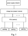
Fig. 1 is a sketch view of a matrix power distribution charging system according to the present invention. -
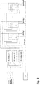
Fig. 2 is a schematic view of the matrix power distribution charging system according to the present invention. -
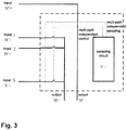
Fig. 3 is a schematic view of a PDU control system according to the present invention. - Referring to the drawings, the present invention will be further illustrated.
- Referring to
Figs. 1-3 , three-phase AC voltage is inputted into a charging box from a power supply network, and is converted into DC voltage for a DC module set. The DC module set comprises a plurality of DC modules, and outputs a plurality of DC power branches to PDUs. The DC modules and the PDUs are respectively connected to a CCU, and each of the PDUs comprises switch devices whose amount equals to an amount of the DC modules, and all the DC modules are connected to each of the PDUs through one of the switch devices; each of the PDUs corresponds to a parking space and is used as a charging source. - According to the method, PDU refers to power distribution unit.
- According to the method, CCU refers to charge control unit.
- According to the method, the DC modules output DC positive voltages, and are respectively connected to the PDUs in parallel, wherein the DC modules are switched on or off by corresponding switch relays.
- Referring to
Fig. 2 , the present invention comprises at least two DC modules or more, and at least two PDUs or more, but an amount of the PDUs must equal to an amount of the DC modules. - Referring to
Fig. 3 , the switch devices are switch relays; each of the PDUs further comprises an AD sampling circuit and an MCU; the switch relays are switched on or off by the MCU, and front voltages of the switch relays are sampled by the AD sampling circuit. - The CCU adopts an MCU.
- The power matching method comprises steps of: sending orders to the DC modules by the CCU after the matrix power distribution charging system is turned on, so as to order the DC modules to output different constant voltage values; meanwhile, sampling front end voltages of the switch relays (front end voltages of the DC modules) by the PDUs through a sampling circuit and sending to the CCU; and comparing the front end voltages of the switch relays with the constant voltage values outputted by the DC modules for determining a corresponding relation between the switch relays and the DC modules;
then logically computing by the CCU according to an actual power requirement of the parking space and sending control orders to the PDUs, so as to switch on or off the switch relays of the PDUs for a certain DC module output combination, in such a manner that the PDUs correctly outputs a certain power. - The power matching method of the matrix power distribution charging system specifically comprises steps as follows.
- Referring to
Fig. 2 , the CCU, PDUs and DC modules in the system communicate with each other through a CAN bus, and respectively have a unique address ID distributed in different address areas. For example, a CCU address range is 0-4, a PDU address range is 5-20, and a DC module address range is 21-50, wherein messages are sent and received through the address ID. During operation, the CCU manages the whole operation progress. Establishing a corresponding relation between the switch relays of the PDUs and each of the DC modules is started by the CCU. - (1) broadcasting a state order by the CCU for indicating that the switch devices begin to match with the DC modules;
- (2) sending messages to each of the DC modules (ID number 21-50) one by one by the CCU, wherein the messages order the DC modules to output the constant voltage values (which are different from each other); meanwhile, receiving the messages by the PDUs, in such a manner that the PDUs know the constant voltage values Vcomm to be outputted by the DC modules;
- (3) respectively outputting the constant voltage values by the DC modules according to the messages from the CCU;
- (4) sampling voltages Vad in front of the switch relays by the PDUs through the AD sampling circuit, and processing the voltages Vad with filtering delay; comparing the voltages Vad with the constant voltage values Vcomm outputted by the DC modules for finding the switch relays and the DC modules with similar output voltage values, and establishing an one-to-one corresponding relation, in such a manner that ID numbers of the DC modules are corresponding to ID numbers of the switch relays of the PDUs;
- (5) sending a matching success message to the CCU by each of the PDUs if matching succeeds after the corresponding relation is established between the switch relays and the DC modules; or sending a matching failure message to the CCU if matching fails; and
- (6) broadcasting a matching complete state to the matrix power distribution charging system when the CCU receives all matching messages of the PDUs.
- In the following example for illustrating the present invention, three DC modules and three PDUs are used.
- Through the CAN bus, the CUU orders the DC modules to output certain voltages, assuming a
DC module 1 is set to 40V, aDC module 2 is set to 80V and a DC module 3 is set to 60V. - For instance, if a sample voltage of a switch relay S-1 of a PDU-1 is 60V, then PDU-1 corresponds to the DC module 3, while sample voltages of S-1 of PDU-2 and S-1 of PDU-3 are both 0.
- If a sample voltage of a switch relay S-2 of a PDU-2 is 40V, then PDU-2 corresponds to the
DC module 1, while sample voltages of S-2 of PDU-1 and S-2 of PDU-3 are both 0. - If a sample voltage of a switch relay S-3 of a PDU-3 is 80V, then PDU-3 corresponds to the
DC module 2, while sample voltages of S-3 of PDU-1 and S-3 of PDU-2 are both 0. - Therefore, in the example, the
DC module 1 corresponds to the PDU-2 and the S-2. TheDC module 2 corresponds to the PDU-3 and the S-3. The DC module 3 corresponds to the PDU-1 and the S-1. - After determining the corresponding relation between the switch relays and the DC modules, a mapping relation is established. When a vehicle is charging in a parking space, the CCU controls a switch relay state of the PDUs, so as to control an output combination of the DC modules for correctly charging.
Claims (5)
- A power matching method of a matrix power distribution charging system, wherein the matrix power distribution charging system comprises at least two DC (direct current) modules and a plurality of PDUs (powder distribution unit), wherein the DC modules and the PDUs are respectively connected to a CCU (charge control unit); each of the PDUs comprises switch devices whose amount equals to an amount of the DC modules, and all the DC modules are connected to each of the PDUs through one of the switch devices; each of the PDUs corresponds to a parking space and is used as a charging source;
wherein the power matching method comprises steps of: sending orders to the DC modules by the CCU after the matrix power distribution charging system is turned on, so as to order the DC modules to output different constant voltage values; meanwhile, sampling front end voltages of the switch devices by the PDUs through a sampling circuit and sending to the CCU; and comparing the front end voltages of the switch devices with the constant voltage values outputted by the DC modules for determining a corresponding relation between the switch devices and the DC modules; finally, logically computing by the CCU according to an actual power requirement of the parking space and sending control orders to the PDUs, so as to switch on or off the switch devices of the PDUs for a certain DC module output combination, in such a manner that the PDUs correctly outputs a certain power. - The power matching method, as recited in claim 1, specifically comprising steps of:(1) broadcasting a state order by the CCU for indicating that the switch devices begin to match with the DC modules;(2) sending messages to each of the DC modules one by one by the CCU to order the DC modules to output the constant voltage values; meanwhile, receiving the messages by the PDUs, in such a manner that the PDUs know the constant voltage values to be outputted by the DC modules;(3) respectively outputting the constant voltage values by the DC modules according to the messages from the CCU;(4) sampling the front end voltages of the switch devices by the PDUs through the sampling circuit, comparing the front end voltages of the switch devices with the constant voltage values outputted by the DC modules for finding the switch devices and the DC modules with similar output voltage values, and establishing an one-to-one corresponding relation;(5) sending a matching success message to the CCU by each of the PDUs if matching succeeds after the corresponding relation is established between the switch devices and the DC modules; or sending a matching failure message to the CCU if matching fails; and(6) broadcasting a matching complete state to the matrix power distribution charging system when the CCU receives all matching messages of the PDUs.
- The power matching method, as recited in claim 1 or 2, wherein the switch devices are switch relays; each of the PDUs further comprises an AD (analog-digital) sampling circuit and an MCU (micro controller unit); the switch relays are switched on or off by the MCU, and front voltages of the switch relays are sampled by the AD sampling circuit.
- The power matching method, as recited in claim 1 or 2, wherein the DC modules and the PDUs are respectively connected to and communicate with the CCU by a CAN (controller area network) bus.
- The power matching method, as recited in claim 1, wherein the CCU adopts an MCU.
Applications Claiming Priority (2)
| Application Number | Priority Date | Filing Date | Title |
|---|---|---|---|
| CN201510551423.7A CN105375552B (en) | 2015-09-01 | 2015-09-01 | A kind of power matching method of matrix form power distribution charging system |
| PCT/CN2016/096809 WO2017036349A1 (en) | 2015-09-01 | 2016-08-26 | Power matching method of matrix power distribution charging system |
Publications (4)
| Publication Number | Publication Date |
|---|---|
| EP3346571A1 true EP3346571A1 (en) | 2018-07-11 |
| EP3346571A4 EP3346571A4 (en) | 2019-08-14 |
| EP3346571C0 EP3346571C0 (en) | 2023-12-27 |
| EP3346571B1 EP3346571B1 (en) | 2023-12-27 |
Family
ID=55377464
Family Applications (1)
| Application Number | Title | Priority Date | Filing Date |
|---|---|---|---|
| EP16840778.1A Active EP3346571B1 (en) | 2015-09-01 | 2016-08-26 | Power matching method of matrix power distribution charging system |
Country Status (4)
| Country | Link |
|---|---|
| US (1) | US10447057B2 (en) |
| EP (1) | EP3346571B1 (en) |
| CN (1) | CN105375552B (en) |
| WO (1) | WO2017036349A1 (en) |
Cited By (5)
| Publication number | Priority date | Publication date | Assignee | Title |
|---|---|---|---|---|
| CN108879903A (en) * | 2018-08-10 | 2018-11-23 | 北京智充科技有限公司 | A kind of multiple gun head direct-current charging post system and its charge power distribution method |
| WO2021209532A1 (en) | 2020-04-16 | 2021-10-21 | Chargepoly | System and method for charging motor vehicles |
| FR3109340A1 (en) * | 2020-04-16 | 2021-10-22 | Chargepoly | SYSTEM AND METHOD OF CHARGING MOTOR VEHICLES |
| WO2024245526A1 (en) * | 2023-05-26 | 2024-12-05 | Siemens Aktiengesellschaft | Multi-vehicle charging arrangement |
| EP4686603A1 (en) | 2024-07-31 | 2026-02-04 | Chargepoly | System and method for charging motor vehicles |
Families Citing this family (35)
| Publication number | Priority date | Publication date | Assignee | Title |
|---|---|---|---|---|
| CN105375552B (en) * | 2015-09-01 | 2017-03-15 | 西安特锐德智能充电科技有限公司 | A kind of power matching method of matrix form power distribution charging system |
| CN106711991A (en) * | 2016-12-23 | 2017-05-24 | 长园深瑞继保自动化有限公司 | Power supply module and distribution method for distributing power freely |
| CN108242828A (en) * | 2016-12-27 | 2018-07-03 | 飞宏科技股份有限公司 | Intelligent power distribution system for charging pile |
| CN107323274B (en) * | 2017-02-14 | 2020-01-24 | 宁波三星智能电气有限公司 | Charging pile system based on Internet of things and control method thereof |
| CN107117049B (en) * | 2017-04-28 | 2019-12-13 | 西安特锐德智能充电科技有限公司 | single-pile multi-gun channel matching method capable of automatically identifying module position |
| CN110015021B (en) * | 2017-09-14 | 2021-01-08 | 深圳智链物联科技有限公司 | A charging socket and charging system for electric vehicles |
| CN108312871B (en) * | 2018-02-02 | 2021-11-16 | 西安特锐德智能充电科技有限公司 | Method and system for controlling current output of power module group |
| CN108279621B (en) * | 2018-04-11 | 2024-07-02 | 山东省科学院能源研究所 | Intelligent isolation type power distribution system and method for intermediate frequency furnace |
| CN109455106B (en) * | 2018-10-17 | 2022-07-26 | 国网浙江省电力有限公司杭州供电公司 | Intelligent charging station for electric automobile |
| CN109591644A (en) * | 2018-11-12 | 2019-04-09 | 江苏万帮德和新能源科技股份有限公司 | DC charging heap dynamic and intelligent power distribution system and its distribution method |
| CN109733230A (en) * | 2018-12-21 | 2019-05-10 | 广西科技大学 | An electric vehicle slow charging with multiple guns and its management system |
| KR102747491B1 (en) * | 2019-10-17 | 2024-12-31 | 삼성전자주식회사 | An electronic device comprising a resonant charging circuit |
| EP4018526B1 (en) | 2019-10-17 | 2025-01-01 | Samsung Electronics Co., Ltd. | Electronic device including resonant charging circuit |
| WO2021075914A1 (en) | 2019-10-17 | 2021-04-22 | Samsung Electronics Co., Ltd. | Electronic device including resonant charging circuit |
| CN112776633B (en) * | 2019-11-07 | 2022-05-17 | 国创移动能源创新中心(江苏)有限公司 | A charging system and method using a mobile power distribution unit |
| CN112238780A (en) * | 2019-11-27 | 2021-01-19 | 北京新能源汽车技术创新中心有限公司 | Charging method, system and vehicle |
| CN111055717B (en) * | 2019-12-30 | 2021-11-05 | 重庆国翰能源发展有限公司 | A group charging system based on high-power flexible distribution of electric vehicles |
| US11424621B2 (en) | 2020-01-28 | 2022-08-23 | Qualcomm Incorporated | Configurable redundant systems for safety critical applications |
| CN111301211A (en) * | 2020-04-17 | 2020-06-19 | 河海大学常州校区 | Super charging pile based on flexible charging power sharing |
| CN111422084B (en) * | 2020-04-27 | 2025-05-30 | 特瓦特能源科技有限公司 | A hierarchical busbar flexible charging system |
| EP4173108A1 (en) * | 2020-06-30 | 2023-05-03 | I-Charging, Mobilidade Electrica, S.A. | Intelligent charging system for electric vehicle batteries in direct current |
| CN111959333B (en) * | 2020-07-28 | 2021-08-27 | 福建星云电子股份有限公司 | Power distribution method, equipment and medium applied to charging pile |
| CN112224081A (en) | 2020-10-15 | 2021-01-15 | 阳光电源股份有限公司 | A multi-gun charging pile and charging pile circuit |
| CN112319298B (en) * | 2020-11-04 | 2022-07-15 | 四川光慧新能源科技有限公司 | A method for coordinating current distribution for multiple charging modules |
| DE102020214260A1 (en) | 2020-11-12 | 2022-05-12 | Siemens Aktiengesellschaft | Method of operation for a loader and loader |
| CN113022338A (en) * | 2021-03-15 | 2021-06-25 | 西安特锐德智能充电科技有限公司 | Direct current charging system |
| CN116601042B (en) * | 2021-04-02 | 2025-09-23 | 浙江吉利控股集团有限公司 | Configuration method, system, device and storage medium for power distribution |
| CN113147477A (en) * | 2021-05-11 | 2021-07-23 | 万帮数字能源股份有限公司 | Management system for power distribution unit of high-power direct-current charger |
| CN113183807A (en) * | 2021-06-11 | 2021-07-30 | 杭州创睿新能源科技有限公司 | Novel modular charging pile design |
| CN113555926A (en) * | 2021-07-14 | 2021-10-26 | 福建星云电子股份有限公司 | Multi-path charging DC cabinet and control method |
| DE102022201140A1 (en) | 2022-02-03 | 2023-08-03 | Volkswagen Aktiengesellschaft | DC charging station, method of operating a DC charging station and AC charging station |
| CN115276191B (en) * | 2022-09-26 | 2023-01-03 | 西安特来电智能充电科技有限公司 | Power distribution method, device, equipment and medium |
| CN115923565B (en) * | 2022-12-30 | 2025-02-14 | 领充新能源科技有限公司 | Power module control method, device and system |
| CN118991509B (en) * | 2024-08-23 | 2025-10-28 | 深圳市道通合创数字能源有限公司 | Power distribution control method, charging host, charging device and chip |
| CN119773569B (en) * | 2025-01-23 | 2025-10-14 | 江西瑞华智能科技有限公司 | Matrix split type direct current charging pile and power distribution method thereof |
Family Cites Families (15)
| Publication number | Priority date | Publication date | Assignee | Title |
|---|---|---|---|---|
| US6081205A (en) * | 1992-05-19 | 2000-06-27 | Williams; Douglas J. | Electronic parking meter and electric automobile recharging station |
| JP2008199752A (en) * | 2007-02-09 | 2008-08-28 | Kyushu Electric Power Co Inc | Charger |
| CN201374569Y (en) * | 2008-12-09 | 2009-12-30 | 剩沅科技股份有限公司 | Charging station |
| KR101009485B1 (en) * | 2010-04-20 | 2011-01-19 | (주)모던텍 | Universal charging device |
| JP5647057B2 (en) * | 2010-05-19 | 2014-12-24 | 株式会社日立製作所 | Charging apparatus, charging control unit, and charging control method |
| KR101585117B1 (en) * | 2011-12-08 | 2016-01-21 | 가부시키가이샤 에네르기 오요 기쥬츠켄큐쇼 | Rapid Charging Power Supply System |
| US9290103B2 (en) * | 2012-02-08 | 2016-03-22 | Control Module, Inc. | EVSE controller system |
| DE102012007158A1 (en) * | 2012-04-07 | 2013-10-10 | Daimler Ag | Device for controlling power flow in motor vehicle e.g. motor car, has switching device that separates electric drive from bidirectionally operable inverter and connects inverter with charging terminal device based on control signal |
| JP5680769B2 (en) * | 2012-07-13 | 2015-03-04 | パナソニックIpマネジメント株式会社 | Storage battery system and control method thereof |
| CN103956894B (en) * | 2014-04-17 | 2017-03-29 | 南京航空航天大学 | A kind of direct current distributed power supply system and its control method based on three Port Translation devices |
| CN204538735U (en) * | 2015-03-20 | 2015-08-05 | 深圳奥特迅电力设备股份有限公司 | Matrix form flexibility charging heap |
| CN105375552B (en) * | 2015-09-01 | 2017-03-15 | 西安特锐德智能充电科技有限公司 | A kind of power matching method of matrix form power distribution charging system |
| US10065519B1 (en) * | 2015-09-30 | 2018-09-04 | Evercharge, Inc. | Location power monitoring and charge distribution using intelligent electric vehicle supply equipment |
| WO2017147612A1 (en) * | 2016-02-25 | 2017-08-31 | California Institute Of Technology | Adaptive charging network using adaptive charging stations for electric vehicles |
| US10150380B2 (en) * | 2016-03-23 | 2018-12-11 | Chargepoint, Inc. | Dynamic allocation of power modules for charging electric vehicles |
-
2015
- 2015-09-01 CN CN201510551423.7A patent/CN105375552B/en active Active
-
2016
- 2016-08-26 EP EP16840778.1A patent/EP3346571B1/en active Active
- 2016-08-26 US US15/741,291 patent/US10447057B2/en active Active
- 2016-08-26 WO PCT/CN2016/096809 patent/WO2017036349A1/en not_active Ceased
Cited By (9)
| Publication number | Priority date | Publication date | Assignee | Title |
|---|---|---|---|---|
| CN108879903A (en) * | 2018-08-10 | 2018-11-23 | 北京智充科技有限公司 | A kind of multiple gun head direct-current charging post system and its charge power distribution method |
| EP3608158A1 (en) * | 2018-08-10 | 2020-02-12 | Beijing X-Charge Co., Ltd. | A multi-plug dc charging pile system and distribution method of its charging power |
| WO2021209532A1 (en) | 2020-04-16 | 2021-10-21 | Chargepoly | System and method for charging motor vehicles |
| FR3109340A1 (en) * | 2020-04-16 | 2021-10-22 | Chargepoly | SYSTEM AND METHOD OF CHARGING MOTOR VEHICLES |
| FR3109339A1 (en) * | 2020-04-16 | 2021-10-22 | Chargepoly | SYSTEM AND METHOD OF CHARGING MOTOR VEHICLES |
| US12528379B2 (en) | 2020-04-16 | 2026-01-20 | Chargepoly | System and method for charging motor vehicles |
| WO2024245526A1 (en) * | 2023-05-26 | 2024-12-05 | Siemens Aktiengesellschaft | Multi-vehicle charging arrangement |
| EP4686603A1 (en) | 2024-07-31 | 2026-02-04 | Chargepoly | System and method for charging motor vehicles |
| FR3165214A1 (en) | 2024-07-31 | 2026-02-06 | Chargepoly | SYSTEM AND METHOD FOR CHARGING MOTOR VEHICLES |
Also Published As
| Publication number | Publication date |
|---|---|
| WO2017036349A1 (en) | 2017-03-09 |
| EP3346571C0 (en) | 2023-12-27 |
| CN105375552A (en) | 2016-03-02 |
| EP3346571A4 (en) | 2019-08-14 |
| EP3346571B1 (en) | 2023-12-27 |
| US20180205235A1 (en) | 2018-07-19 |
| CN105375552B (en) | 2017-03-15 |
| US10447057B2 (en) | 2019-10-15 |
Similar Documents
| Publication | Publication Date | Title |
|---|---|---|
| US10447057B2 (en) | Power matching method of matrix power distribution charging system | |
| WO2020023933A3 (en) | Light electric vehicle parking and charging stations and smart charging systems for the vehicle batteries | |
| CN105691223B (en) | Charging device capable of automatically identifying charging voltage of electric automobile by charger | |
| EP3671998A3 (en) | System for servicing cable | |
| CN104184195B (en) | A power supply system that improves the reliability and maintainability of unmanned helicopters | |
| US11108252B2 (en) | Charging sequence control of a power electronics system | |
| EP2777975A3 (en) | Power relay assembly driving apparatus and driving method thereof | |
| CN102183953A (en) | Vehicle power electronic unit (PEU) testboard | |
| CN106558902B (en) | Electric vehicle charging circuit and charging method | |
| CN110488167A (en) | A kind of pure electric automobile Insulation Inspection System and method with contactor adhesion judgement | |
| US20170085170A1 (en) | Bi-directional direct current to direct current converter and grid-connected inverter system | |
| US20170163082A1 (en) | Electric voltage system and method for charging a battery of an electric voltage system | |
| CN104802655A (en) | Open circuit diagnosis system of high-voltage direct current end of electric driving system of electric automobile | |
| CN105034841A (en) | Strong electricity charging and discharging control method of hybrid electric vehicle and apparatus thereof | |
| KR20190122947A (en) | Device for electrical vehicle charging | |
| CN107020967A (en) | Charging system | |
| US11664676B2 (en) | PoE emergency power systems and related methods | |
| CN214647657U (en) | Intelligent charging stake controlling means | |
| CN104977546B (en) | A kind of Secondary Direct Electrical Resources towards transformer station lose method of discrimination | |
| CN204012861U (en) | The quick bleeder of a kind of high-power DC power supply | |
| CN104333115A (en) | Simulated power transfer control device and power transfer control method realized by adopting same | |
| CN205427133U (en) | A stretcher for subway signal modules simulation tests | |
| CN109213001A (en) | Aircraft level-one electric power distribution network analog machine and analog equivalent Trial Verification Installation | |
| CN106405262A (en) | Vehicle-mounted multi-unmanned-aerial-vehicle rapid power supply test and starting system | |
| CN204029185U (en) | A kind of BMS practical traning platform |
Legal Events
| Date | Code | Title | Description |
|---|---|---|---|
| STAA | Information on the status of an ep patent application or granted ep patent |
Free format text: STATUS: THE INTERNATIONAL PUBLICATION HAS BEEN MADE |
|
| PUAI | Public reference made under article 153(3) epc to a published international application that has entered the european phase |
Free format text: ORIGINAL CODE: 0009012 |
|
| STAA | Information on the status of an ep patent application or granted ep patent |
Free format text: STATUS: REQUEST FOR EXAMINATION WAS MADE |
|
| 17P | Request for examination filed |
Effective date: 20171220 |
|
| AK | Designated contracting states |
Kind code of ref document: A1 Designated state(s): AL AT BE BG CH CY CZ DE DK EE ES FI FR GB GR HR HU IE IS IT LI LT LU LV MC MK MT NL NO PL PT RO RS SE SI SK SM TR |
|
| AX | Request for extension of the european patent |
Extension state: BA ME |
|
| DAV | Request for validation of the european patent (deleted) | ||
| DAX | Request for extension of the european patent (deleted) | ||
| A4 | Supplementary search report drawn up and despatched |
Effective date: 20190716 |
|
| RIC1 | Information provided on ipc code assigned before grant |
Ipc: B60L 53/30 20190101ALI20190710BHEP Ipc: B60L 53/67 20190101ALI20190710BHEP Ipc: H02J 7/00 20060101AFI20190710BHEP Ipc: B60L 53/62 20190101ALI20190710BHEP Ipc: B60L 53/10 20190101ALI20190710BHEP |
|
| STAA | Information on the status of an ep patent application or granted ep patent |
Free format text: STATUS: EXAMINATION IS IN PROGRESS |
|
| 17Q | First examination report despatched |
Effective date: 20210719 |
|
| REG | Reference to a national code |
Ref country code: DE Ref legal event code: R079 Ref document number: 602016085035 Country of ref document: DE Free format text: PREVIOUS MAIN CLASS: H02J0007000000 Ipc: B60L0053670000 |
|
| RIC1 | Information provided on ipc code assigned before grant |
Ipc: B60L 53/30 20190101ALI20230501BHEP Ipc: B60L 53/10 20190101ALI20230501BHEP Ipc: B60L 53/62 20190101ALI20230501BHEP Ipc: H02J 7/00 20060101ALI20230501BHEP Ipc: B60L 53/60 20190101ALI20230501BHEP Ipc: B60L 53/67 20190101AFI20230501BHEP |
|
| GRAP | Despatch of communication of intention to grant a patent |
Free format text: ORIGINAL CODE: EPIDOSNIGR1 |
|
| STAA | Information on the status of an ep patent application or granted ep patent |
Free format text: STATUS: GRANT OF PATENT IS INTENDED |
|
| INTG | Intention to grant announced |
Effective date: 20230626 |
|
| GRAS | Grant fee paid |
Free format text: ORIGINAL CODE: EPIDOSNIGR3 |
|
| GRAA | (expected) grant |
Free format text: ORIGINAL CODE: 0009210 |
|
| STAA | Information on the status of an ep patent application or granted ep patent |
Free format text: STATUS: THE PATENT HAS BEEN GRANTED |
|
| AK | Designated contracting states |
Kind code of ref document: B1 Designated state(s): AL AT BE BG CH CY CZ DE DK EE ES FI FR GB GR HR HU IE IS IT LI LT LU LV MC MK MT NL NO PL PT RO RS SE SI SK SM TR |
|
| RAP3 | Party data changed (applicant data changed or rights of an application transferred) |
Owner name: XI'AN TELD INTELLIGENT CHARGING TECHNOLOGY CO., LTD. |
|
| REG | Reference to a national code |
Ref country code: GB Ref legal event code: FG4D |
|
| REG | Reference to a national code |
Ref country code: CH Ref legal event code: EP |
|
| REG | Reference to a national code |
Ref country code: DE Ref legal event code: R096 Ref document number: 602016085035 Country of ref document: DE |
|
| REG | Reference to a national code |
Ref country code: IE Ref legal event code: FG4D |
|
| U01 | Request for unitary effect filed |
Effective date: 20240125 |
|
| U07 | Unitary effect registered |
Designated state(s): AT BE BG DE DK EE FI FR IT LT LU LV MT NL PT SE SI Effective date: 20240202 |
|
| PG25 | Lapsed in a contracting state [announced via postgrant information from national office to epo] |
Ref country code: GR Free format text: LAPSE BECAUSE OF FAILURE TO SUBMIT A TRANSLATION OF THE DESCRIPTION OR TO PAY THE FEE WITHIN THE PRESCRIBED TIME-LIMIT Effective date: 20240328 |
|
| PG25 | Lapsed in a contracting state [announced via postgrant information from national office to epo] |
Ref country code: ES Free format text: LAPSE BECAUSE OF FAILURE TO SUBMIT A TRANSLATION OF THE DESCRIPTION OR TO PAY THE FEE WITHIN THE PRESCRIBED TIME-LIMIT Effective date: 20231227 |
|
| PG25 | Lapsed in a contracting state [announced via postgrant information from national office to epo] |
Ref country code: GR Free format text: LAPSE BECAUSE OF FAILURE TO SUBMIT A TRANSLATION OF THE DESCRIPTION OR TO PAY THE FEE WITHIN THE PRESCRIBED TIME-LIMIT Effective date: 20240328 Ref country code: ES Free format text: LAPSE BECAUSE OF FAILURE TO SUBMIT A TRANSLATION OF THE DESCRIPTION OR TO PAY THE FEE WITHIN THE PRESCRIBED TIME-LIMIT Effective date: 20231227 |
|
| PG25 | Lapsed in a contracting state [announced via postgrant information from national office to epo] |
Ref country code: RS Free format text: LAPSE BECAUSE OF FAILURE TO SUBMIT A TRANSLATION OF THE DESCRIPTION OR TO PAY THE FEE WITHIN THE PRESCRIBED TIME-LIMIT Effective date: 20231227 Ref country code: NO Free format text: LAPSE BECAUSE OF FAILURE TO SUBMIT A TRANSLATION OF THE DESCRIPTION OR TO PAY THE FEE WITHIN THE PRESCRIBED TIME-LIMIT Effective date: 20240327 Ref country code: HR Free format text: LAPSE BECAUSE OF FAILURE TO SUBMIT A TRANSLATION OF THE DESCRIPTION OR TO PAY THE FEE WITHIN THE PRESCRIBED TIME-LIMIT Effective date: 20231227 |
|
| PG25 | Lapsed in a contracting state [announced via postgrant information from national office to epo] |
Ref country code: IS Free format text: LAPSE BECAUSE OF FAILURE TO SUBMIT A TRANSLATION OF THE DESCRIPTION OR TO PAY THE FEE WITHIN THE PRESCRIBED TIME-LIMIT Effective date: 20240427 |
|
| PG25 | Lapsed in a contracting state [announced via postgrant information from national office to epo] |
Ref country code: CZ Free format text: LAPSE BECAUSE OF FAILURE TO SUBMIT A TRANSLATION OF THE DESCRIPTION OR TO PAY THE FEE WITHIN THE PRESCRIBED TIME-LIMIT Effective date: 20231227 |
|
| PG25 | Lapsed in a contracting state [announced via postgrant information from national office to epo] |
Ref country code: SK Free format text: LAPSE BECAUSE OF FAILURE TO SUBMIT A TRANSLATION OF THE DESCRIPTION OR TO PAY THE FEE WITHIN THE PRESCRIBED TIME-LIMIT Effective date: 20231227 |
|
| PG25 | Lapsed in a contracting state [announced via postgrant information from national office to epo] |
Ref country code: SM Free format text: LAPSE BECAUSE OF FAILURE TO SUBMIT A TRANSLATION OF THE DESCRIPTION OR TO PAY THE FEE WITHIN THE PRESCRIBED TIME-LIMIT Effective date: 20231227 Ref country code: SK Free format text: LAPSE BECAUSE OF FAILURE TO SUBMIT A TRANSLATION OF THE DESCRIPTION OR TO PAY THE FEE WITHIN THE PRESCRIBED TIME-LIMIT Effective date: 20231227 Ref country code: RO Free format text: LAPSE BECAUSE OF FAILURE TO SUBMIT A TRANSLATION OF THE DESCRIPTION OR TO PAY THE FEE WITHIN THE PRESCRIBED TIME-LIMIT Effective date: 20231227 Ref country code: IS Free format text: LAPSE BECAUSE OF FAILURE TO SUBMIT A TRANSLATION OF THE DESCRIPTION OR TO PAY THE FEE WITHIN THE PRESCRIBED TIME-LIMIT Effective date: 20240427 Ref country code: CZ Free format text: LAPSE BECAUSE OF FAILURE TO SUBMIT A TRANSLATION OF THE DESCRIPTION OR TO PAY THE FEE WITHIN THE PRESCRIBED TIME-LIMIT Effective date: 20231227 |
|
| PG25 | Lapsed in a contracting state [announced via postgrant information from national office to epo] |
Ref country code: PL Free format text: LAPSE BECAUSE OF FAILURE TO SUBMIT A TRANSLATION OF THE DESCRIPTION OR TO PAY THE FEE WITHIN THE PRESCRIBED TIME-LIMIT Effective date: 20231227 |
|
| PG25 | Lapsed in a contracting state [announced via postgrant information from national office to epo] |
Ref country code: PL Free format text: LAPSE BECAUSE OF FAILURE TO SUBMIT A TRANSLATION OF THE DESCRIPTION OR TO PAY THE FEE WITHIN THE PRESCRIBED TIME-LIMIT Effective date: 20231227 |
|
| U20 | Renewal fee for the european patent with unitary effect paid |
Year of fee payment: 9 Effective date: 20240726 |
|
| REG | Reference to a national code |
Ref country code: DE Ref legal event code: R097 Ref document number: 602016085035 Country of ref document: DE |
|
| U1N | Appointed representative for the unitary patent procedure changed after the registration of the unitary effect |
Representative=s name: KARO IP; DE |
|
| PLBE | No opposition filed within time limit |
Free format text: ORIGINAL CODE: 0009261 |
|
| STAA | Information on the status of an ep patent application or granted ep patent |
Free format text: STATUS: NO OPPOSITION FILED WITHIN TIME LIMIT |
|
| 26N | No opposition filed |
Effective date: 20240930 |
|
| REG | Reference to a national code |
Ref country code: CH Ref legal event code: PL |
|
| GBPC | Gb: european patent ceased through non-payment of renewal fee |
Effective date: 20240826 |
|
| PG25 | Lapsed in a contracting state [announced via postgrant information from national office to epo] |
Ref country code: MC Free format text: LAPSE BECAUSE OF FAILURE TO SUBMIT A TRANSLATION OF THE DESCRIPTION OR TO PAY THE FEE WITHIN THE PRESCRIBED TIME-LIMIT Effective date: 20231227 Ref country code: CH Free format text: LAPSE BECAUSE OF NON-PAYMENT OF DUE FEES Effective date: 20240831 |
|
| PG25 | Lapsed in a contracting state [announced via postgrant information from national office to epo] |
Ref country code: GB Free format text: LAPSE BECAUSE OF NON-PAYMENT OF DUE FEES Effective date: 20240826 |
|
| PG25 | Lapsed in a contracting state [announced via postgrant information from national office to epo] |
Ref country code: IE Free format text: LAPSE BECAUSE OF NON-PAYMENT OF DUE FEES Effective date: 20240826 |
|
| U20 | Renewal fee for the european patent with unitary effect paid |
Year of fee payment: 10 Effective date: 20250826 |
|
| PG25 | Lapsed in a contracting state [announced via postgrant information from national office to epo] |
Ref country code: CY Free format text: LAPSE BECAUSE OF FAILURE TO SUBMIT A TRANSLATION OF THE DESCRIPTION OR TO PAY THE FEE WITHIN THE PRESCRIBED TIME-LIMIT; INVALID AB INITIO Effective date: 20160826 |
|
| PG25 | Lapsed in a contracting state [announced via postgrant information from national office to epo] |
Ref country code: HU Free format text: LAPSE BECAUSE OF FAILURE TO SUBMIT A TRANSLATION OF THE DESCRIPTION OR TO PAY THE FEE WITHIN THE PRESCRIBED TIME-LIMIT; INVALID AB INITIO Effective date: 20160826 |