EP3346566A1 - 3 phase undervoltage trip device and molded case circuit breaker therewith - Google Patents
3 phase undervoltage trip device and molded case circuit breaker therewith Download PDFInfo
- Publication number
- EP3346566A1 EP3346566A1 EP17173189.6A EP17173189A EP3346566A1 EP 3346566 A1 EP3346566 A1 EP 3346566A1 EP 17173189 A EP17173189 A EP 17173189A EP 3346566 A1 EP3346566 A1 EP 3346566A1
- Authority
- EP
- European Patent Office
- Prior art keywords
- phase
- voltage
- trip device
- circuit breaker
- rectification
- Prior art date
- Legal status (The legal status is an assumption and is not a legal conclusion. Google has not performed a legal analysis and makes no representation as to the accuracy of the status listed.)
- Withdrawn
Links
Images
Classifications
-
- H—ELECTRICITY
- H01—ELECTRIC ELEMENTS
- H01H—ELECTRIC SWITCHES; RELAYS; SELECTORS; EMERGENCY PROTECTIVE DEVICES
- H01H71/00—Details of the protective switches or relays covered by groups H01H73/00 - H01H83/00
- H01H71/10—Operating or release mechanisms
-
- H—ELECTRICITY
- H01—ELECTRIC ELEMENTS
- H01H—ELECTRIC SWITCHES; RELAYS; SELECTORS; EMERGENCY PROTECTIVE DEVICES
- H01H71/00—Details of the protective switches or relays covered by groups H01H73/00 - H01H83/00
- H01H71/10—Operating or release mechanisms
- H01H71/12—Automatic release mechanisms with or without manual release
- H01H71/123—Automatic release mechanisms with or without manual release using a solid-state trip unit
-
- H—ELECTRICITY
- H01—ELECTRIC ELEMENTS
- H01H—ELECTRIC SWITCHES; RELAYS; SELECTORS; EMERGENCY PROTECTIVE DEVICES
- H01H33/00—High-tension or heavy-current switches with arc-extinguishing or arc-preventing means
- H01H33/02—Details
- H01H33/022—Details particular to three-phase circuit breakers
-
- H—ELECTRICITY
- H01—ELECTRIC ELEMENTS
- H01H—ELECTRIC SWITCHES; RELAYS; SELECTORS; EMERGENCY PROTECTIVE DEVICES
- H01H71/00—Details of the protective switches or relays covered by groups H01H73/00 - H01H83/00
- H01H71/10—Operating or release mechanisms
- H01H71/12—Automatic release mechanisms with or without manual release
- H01H71/123—Automatic release mechanisms with or without manual release using a solid-state trip unit
- H01H71/125—Automatic release mechanisms with or without manual release using a solid-state trip unit characterised by sensing elements, e.g. current transformers
-
- H—ELECTRICITY
- H01—ELECTRIC ELEMENTS
- H01H—ELECTRIC SWITCHES; RELAYS; SELECTORS; EMERGENCY PROTECTIVE DEVICES
- H01H71/00—Details of the protective switches or relays covered by groups H01H73/00 - H01H83/00
- H01H71/10—Operating or release mechanisms
- H01H71/12—Automatic release mechanisms with or without manual release
- H01H71/128—Manual release or trip mechanisms, e.g. for test purposes
-
- H—ELECTRICITY
- H01—ELECTRIC ELEMENTS
- H01H—ELECTRIC SWITCHES; RELAYS; SELECTORS; EMERGENCY PROTECTIVE DEVICES
- H01H71/00—Details of the protective switches or relays covered by groups H01H73/00 - H01H83/00
- H01H71/10—Operating or release mechanisms
- H01H71/12—Automatic release mechanisms with or without manual release
- H01H71/24—Electromagnetic mechanisms
-
- H—ELECTRICITY
- H01—ELECTRIC ELEMENTS
- H01H—ELECTRIC SWITCHES; RELAYS; SELECTORS; EMERGENCY PROTECTIVE DEVICES
- H01H73/00—Protective overload circuit-breaking switches in which excess current opens the contacts by automatic release of mechanical energy stored by previous operation of a hand reset mechanism
- H01H73/02—Details
- H01H73/04—Contacts
-
- H—ELECTRICITY
- H01—ELECTRIC ELEMENTS
- H01H—ELECTRIC SWITCHES; RELAYS; SELECTORS; EMERGENCY PROTECTIVE DEVICES
- H01H83/00—Protective switches, e.g. circuit-breaking switches, or protective relays operated by abnormal electrical conditions otherwise than solely by excess current
- H01H83/12—Protective switches, e.g. circuit-breaking switches, or protective relays operated by abnormal electrical conditions otherwise than solely by excess current operated by voltage falling below a predetermined value, e.g. for no-volt protection
-
- H—ELECTRICITY
- H01—ELECTRIC ELEMENTS
- H01H—ELECTRIC SWITCHES; RELAYS; SELECTORS; EMERGENCY PROTECTIVE DEVICES
- H01H83/00—Protective switches, e.g. circuit-breaking switches, or protective relays operated by abnormal electrical conditions otherwise than solely by excess current
- H01H83/14—Protective switches, e.g. circuit-breaking switches, or protective relays operated by abnormal electrical conditions otherwise than solely by excess current operated by imbalance of two or more currents or voltages, e.g. for differential protection
-
- H—ELECTRICITY
- H02—GENERATION; CONVERSION OR DISTRIBUTION OF ELECTRIC POWER
- H02H—EMERGENCY PROTECTIVE CIRCUIT ARRANGEMENTS
- H02H3/00—Emergency protective circuit arrangements for automatic disconnection directly responsive to an undesired change from normal electric working condition with or without subsequent reconnection ; integrated protection
- H02H3/24—Emergency protective circuit arrangements for automatic disconnection directly responsive to an undesired change from normal electric working condition with or without subsequent reconnection ; integrated protection responsive to undervoltage or no-voltage
- H02H3/253—Emergency protective circuit arrangements for automatic disconnection directly responsive to an undesired change from normal electric working condition with or without subsequent reconnection ; integrated protection responsive to undervoltage or no-voltage for multiphase applications, e.g. phase interruption
-
- H—ELECTRICITY
- H01—ELECTRIC ELEMENTS
- H01H—ELECTRIC SWITCHES; RELAYS; SELECTORS; EMERGENCY PROTECTIVE DEVICES
- H01H71/00—Details of the protective switches or relays covered by groups H01H73/00 - H01H83/00
- H01H71/10—Operating or release mechanisms
- H01H71/12—Automatic release mechanisms with or without manual release
- H01H71/123—Automatic release mechanisms with or without manual release using a solid-state trip unit
- H01H2071/124—Automatic release mechanisms with or without manual release using a solid-state trip unit with a hybrid structure, the solid state trip device being combined with a thermal or a electromagnetic trip
Definitions
- the present disclosure relates to a 3-phase undervoltage trip device for automatically tripping (shutting off) a circuit breaker by detecting an open phase based on undervoltage of a 3-phase line, and a molded case circuit breaker having the same.
- a molded case circuit breaker is installed in a distribution board in a power reception and distribution facility of a factory, a building, or the like, and serves as a switching device for supplying or interrupting power to the loads in the idling condition.
- the circuit breaker also serves to cut off power supplied from the power source to the loads in order to protect the wires and the load devices on the line when a large current exceeding the load current flows due to the abnormal condition of the load line during use of the loads.
- the MCCB includes an undervoltage trip device capable of tripping a circuit to prevent damage to the circuit and a load device connected to the circuit when the applied voltage drops below a predetermined value due to disconnection or the like.
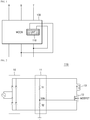
- FIG. 1 is a schematic view of an MCCB equipped with a conventional undervoltage trip device.
- line voltages of any two phases (e.g., S, T) of the 3 phases (R, S, T) may be applied to a power supply terminal of an undervoltage trip device 110 mounted on a conventional MCCB 100.
- the undervoltage trip device 110 senses the level of the line voltages of two phases (e.g., S, T) 10 in the energized state.
- the undervoltage trip device 110 trips (shuts off) the circuit to prevent damage to the circuit and the load devices connected to the circuit.
- FIG. 2 is a circuit diagram of the conventional undervoltage trip device 110.
- the conventional undervoltage trip device 110 includes a rectifier 10 for rectifying voltages (alternating current (AC) voltages) of any two phases (e.g., S, T), a voltage divider 11 for dividing the line voltages (direct current (DC) voltage) obtained through rectification in the rectifier 10, a switch 12 which is turned on/off by the divided voltage Vdiv produced by the voltage divider 11, and an excitation coil 13 magnetized or demagnetized according to a current to magnetize (or demagnetize) a circuit-breaking fixed core (not shown).
- AC alternating current
- DC direct current
- the voltage divider 11 includes two resistors R1 and R2 connected in series and the divided voltage Vdiv is determined by the resistance ratio of R1 and R2.
- the rectifier 10 may include a bridge diode, and the switch 12 may include a MOSFET.
- the divided voltage Vdiv output from the voltage divider 11 becomes higher than the turn-on voltage of the switch 12 (or gate-source voltage of the MOSFET).
- the switch 12 is turned on by the divided voltage Vdiv, the circuit inside the device forms a closed loop, and the energizing current flows through the excitation coil 13.
- the excitation coil 13 is magnetized by the energizing current to magnetize a neighboring fixed core, thereby maintaining the circuit in a steady state.
- the two-phase (e.g., S, T) voltage level is lowered (open phase) due to disconnection or the like
- the divided voltage Vdiv of the voltage divider 11 becomes lower than the turn-on voltage of the switch 12.
- the switch 12 is turned off, the internal circuit forms an open loop according to turning-off of the switch 12, and the energizing current passing through the switch 13 is cut off. Therefore, the excitation coil 13 and the fixed core previously magnetized by the energizing current are demagnetized, operating the circuit breaker (not shown). Thereby, the circuit is tripped.
- the conventional undervoltage trip device is connected to any two phases (e.g., S, T) of the three phases (R, S, T) to perform a trip operation in the event of disconnection or detection of an accident, it may not recognize disconnection or occurrence of an accident with respect to the other phase R, and thus line trip (shut off) may not be performed for the phase R.
- a molded case circuit breaker may include lines to which a 3-phase power is applied and a 3-phase undervoltage trip device connected to lines and configured to operate to automatically trip a circuit when an open phase condition occurs on any one of three phases of the power.
- the 3-phase power includes R, S, and T phase powers.
- the 3-phase undervoltage trip device may include: a rectifier connected to the lines and configured to rectify the 3-phase power applied to the lines and output 3-phase line voltages; a divider configured to distribute an average voltage of the 3-phase line voltages rectified by the rectifier; an amplifier configured to amplify the average voltage distributed by the divider; a comparator configured to compare the average voltage amplified by the amplifier with a reference voltage and output an open phase detection signal; and a switch turned on or off according to the open phase detection signal of the comparator and operated to supply a current to an excitation coil for tripping the circuit breaker when turned on.
- the amplifier may include an OP amplifier, and the switch may include a MOSFET.
- the 3-phase undervoltage trip device may further include a phase detector enabled by the open phase detection signal output by the comparator to detect a phase having the open phase condition when the open phase condition occurs.
- the open phase detector may include: first and second rectification and division units configured to rectify and divide line voltages of two phases among the line voltages of the three phases; and a second comparator configured to compare the divided voltages from the first and second rectification and division units and outputting a comparison signal indicating a phase having the open phase condition.
- the first and second first and second rectification and division units may commonly receive the line voltage of one phase and divide the voltage with the same resistance ratio.
- the circuit can be tripped when the open phase condition occurs on any one of the three phases, occurrence of the open phase condition due to disconnection or an accident on the line may be easily detected. Accordingly, the circuit may be tripped with high accuracy and high stability.
- an open phase detection signal that is output from an undervoltage trip device when the open phase condition occurs is used as an enable signal of an open phase detector. Accordingly, the open phase detector may detect a phase that is in the open phase condition, with a high accuracy.
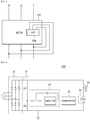
- FIG. 3 is a schematic diagram of an MCCB 100 equipped with a 3-phase undervoltage trip device 200 according to an embodiment of the present disclosure.
- the 3-phase undervoltage trip device 200 is connected to 3-phase (R, S, T) lines to monitor the states of 3-phase line voltages.
- 3-phase (R, S, T) lines to monitor the states of 3-phase line voltages.
- the 3-phase undervoltage trip device 200 trips (shuts off) the circuit to prevent damage to the circuit and load devices connected to the circuit.
- FIG. 4 is a detailed circuit diagram of the 3-phase undervoltage trip device 200 according to an embodiment of the present disclosure.
- the 3-phase undervoltage trip device 200 includes a rectifier 20 for rectifying 3-phase (R, S, T) line voltages (AC voltages), a voltage divider 21 for dividing the 3-phase line voltages (DC voltages) rectified by the rectifier 20 and outputting an average value thereof, an amplifier 22 for amplifying the voltage average value output from the voltage divider 20, a comparator 23 for comparing the voltage average value output from the amplifier 22 with a reference voltage value and outputting an open phase detection signal, a switch 24 to be turned on/off according to the open phase detection signal output from the comparator 23, an excitation coil (not shown) to be magnetized (or demagnetized) according to a current flowing through turning on/off of the switch 24 to magnetize (or demagnetize) a circuit-breaking fixed core (not shown) for tripping the circuit breaker (not shown).
- a rectifier 20 for rectifying 3-phase (R, S, T) line voltages (AC voltages)
- a voltage divider 21 for dividing the 3-phase line voltages
- the rectifier 10 may include a bridge diode.
- the voltage divider 21 includes two resistors R1 and R2 connected in series and divides the 3-phase line voltages based on the resistance ratio of the resistors R1 and R2 to output a voltage average value (average line voltage).
- the amplifier 22 may include an OP-Amplifier, and the switch 24 may include a MOSFET.
- the switch 24 may include a MOSFET.
- embodiments of the present disclosure are not limited thereto.
- Various switches may be included.
- the 3-phase (R, S, T) voltages are normally applied to the lines, the 3-phase voltages rectified in the rectifier 20 are divided by the voltage divider 21. At this time, the divided voltage produced by the voltage divider 21 is set to an average value of the 3-phase voltages.
- the average line voltage output from the voltage divider 21 is amplified by the amplifier 22 and then input to the comparator 23.
- the comparator 23 compares the input average line voltage with a preset reference voltage, and outputs a comparison signal of a high level, more specifically, an open phase detection signal indicating that the open phase condition has not occurred.
- the reference voltage is set to be smaller than the average line voltage. Therefore, when the 3-phase (R, S, T) voltages are normally applied to the line, the comparator 23 outputs, to the switch 24, a high-level open phase detection signal indicating that the open phase has not been detected, thereby turning on the switch 24, more specifically the MOSFET.
- the switch 24 is turned on by the high-level open phase detection signal, the internal circuit forms a closed loop, and thus the energizing current flows through the excitation coil 25. Accordingly, the excitation coil 25 is magnetized by the current to magnetize the neighboring fixed core. Thereby, the circuit maintains the steady state.
- the comparator 23 outputs a low-level comparison signal, more specifically, an open phase detection signal indicating occurrence of the open phase condition, thereby turning off the switch 24.
- the switch 24 When the switch 24 is turned off by the low-level open phase detection signal, the internal circuit forms an open loop, and the current flowing through the excitation coil 25 is cut off by turning off the switch 24. Thereby, the excitation coil 25 is demagnetized. When the excitation coil 25 is turned off, the neighboring fixed core is demagnetized. Thereby, the circuit breaker (not shown) is operated and the circuit is tripped.
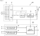
- FIG. 5 is a diagram illustrating an application example of a 3-phase undervoltage trip device 200 according to an embodiment of the present disclosure.
- the open phase detection signal output from the 3-phase undervoltage trip device 200 of the present disclosure may be used as an operation signal of an open phase detector 300, which detects a phase on which the open phase condition has occurred.
- the open phase detector 300 may include first and second rectification and division units 30 and 31 for rectifying and dividing line voltages of two phases and a second comparator 32 for comparing the divided voltages produced by the first and second rectification and division units 30 and 31 and outputting a comparison signal indicating a phase on which the open phase condition has actually occurred.
- the first and second rectification and division units 30 and 31 receive a line voltage of one phase in common among the 3-phase line voltages.
- the same resistance ratio for dividing the voltages is set.
- the first and second rectification and division units 30 and 31 receive the line voltage of the S phase in common.
- the first rectification and division unit 30 receives the line voltages of the R and S phases
- the second rectification and division unit 31 receives the line voltages of the S and T phases.
- the second comparator 300 is enabled (or triggered) according to the low-level comparison signal output from the first comparator 23 of the 3-phase undervoltage trip device 200, and compares the divided voltage from the first rectification with division unit 30 and the divided voltage from the second rectification and division unit 31 to determine the higher one of the divided voltages.
- the 3-phase undervoltage trip device 200 may control the circuit breaker to trip the circuit, and at the same time, output a low-level comparison signal, more specifically, the open phase detection signal to the open phase detection unit 300 to enable the open phase detection unit 300.
- the first and second rectification with division units 30 and 31 of the open phase detector 300 receive the line voltage of one phase in common among the 3-phase line voltages, it is possible to know the phase on which the open phase condition has occurred according to the result of comparison.
- the divided voltage output from the first rectification and division unit 30 is lower than the divided voltage output from the second rectification and division unit 31, and thus the second comparator 32 outputs a low-level comparison signal.
- the second comparator 32 outputs a high-level comparison signal using the same method.
- a phase on which the open phase condition occurs may be easily recognized, based on the comparison signal output from the second comparator 32.
- a circuit or device using two-phase line voltages may stably perform line switching.
- the 3-phase undervoltage trip device 200 of this embodiment may determine whether or not the open phase condition has occurred on at least one of the three phases through the first comparator 23, and determine a phase having the open phase condition among the three phases, through the second comparator 23.
- two rectification and division units have been described as an example, but the present disclosure is not limited thereto.
- three or more rectification and division units may be provided, and the second comparator 32 may compare the output voltages of the plurality of rectification and division units to detect a phase on which the open phase condition has occurred among the phases connected to the rectification and division units.
- the 3-phase undervoltage trip device of this embodiment may operate to trip the circuit when the open phase condition occurs on any one of the three phases. Therefore, the 3-phase undervoltage trip device may detect occurrence of the open phase condition caused by disconnection or an accident on the line, with high accuracy and may be effectively applied to line switching or the like.
Landscapes
- Physics & Mathematics (AREA)
- Electromagnetism (AREA)
- Emergency Protection Circuit Devices (AREA)
- Engineering & Computer Science (AREA)
- Power Engineering (AREA)
Abstract
Description
- The present disclosure relates to a 3-phase undervoltage trip device for automatically tripping (shutting off) a circuit breaker by detecting an open phase based on undervoltage of a 3-phase line, and a molded case circuit breaker having the same.
- In general, a molded case circuit breaker (MCCB) is installed in a distribution board in a power reception and distribution facility of a factory, a building, or the like, and serves as a switching device for supplying or interrupting power to the loads in the idling condition. The circuit breaker also serves to cut off power supplied from the power source to the loads in order to protect the wires and the load devices on the line when a large current exceeding the load current flows due to the abnormal condition of the load line during use of the loads.
- For this purpose, the MCCB includes an undervoltage trip device capable of tripping a circuit to prevent damage to the circuit and a load device connected to the circuit when the applied voltage drops below a predetermined value due to disconnection or the like.
-
FIG. 1 is a schematic view of an MCCB equipped with a conventional undervoltage trip device. - As shown in
FIG. 1 , line voltages of any two phases (e.g., S, T) of the 3 phases (R, S, T) may be applied to a power supply terminal of anundervoltage trip device 110 mounted on aconventional MCCB 100.. Theundervoltage trip device 110 senses the level of the line voltages of two phases (e.g., S, T) 10 in the energized state. When the line voltages of two phases (S, T) become 35% to 70% of the rated voltage due to an accident on the line and thus undervoltage occurs, theundervoltage trip device 110 trips (shuts off) the circuit to prevent damage to the circuit and the load devices connected to the circuit. -
FIG. 2 is a circuit diagram of the conventionalundervoltage trip device 110. - Referring to
FIG. 2 , the conventionalundervoltage trip device 110 includes arectifier 10 for rectifying voltages (alternating current (AC) voltages) of any two phases (e.g., S, T), avoltage divider 11 for dividing the line voltages (direct current (DC) voltage) obtained through rectification in therectifier 10, aswitch 12 which is turned on/off by the divided voltage Vdiv produced by thevoltage divider 11, and anexcitation coil 13 magnetized or demagnetized according to a current to magnetize (or demagnetize) a circuit-breaking fixed core (not shown). - The
voltage divider 11 includes two resistors R1 and R2 connected in series and the divided voltage Vdiv is determined by the resistance ratio of R1 and R2. Therectifier 10 may include a bridge diode, and theswitch 12 may include a MOSFET. - When the two-phase (e.g., S, T) voltage is normally applied to the line, the divided voltage Vdiv output from the
voltage divider 11 becomes higher than the turn-on voltage of the switch 12 (or gate-source voltage of the MOSFET). When theswitch 12 is turned on by the divided voltage Vdiv, the circuit inside the device forms a closed loop, and the energizing current flows through theexcitation coil 13. Thus, theexcitation coil 13 is magnetized by the energizing current to magnetize a neighboring fixed core, thereby maintaining the circuit in a steady state. - On the other hand, when the two-phase (e.g., S, T) voltage level is lowered (open phase) due to disconnection or the like, the divided voltage Vdiv of the
voltage divider 11 becomes lower than the turn-on voltage of theswitch 12. When the divided voltage Vdiv becomes lower than the turn-on voltage of theswitch 12, theswitch 12 is turned off, the internal circuit forms an open loop according to turning-off of theswitch 12, and the energizing current passing through theswitch 13 is cut off. Therefore, theexcitation coil 13 and the fixed core previously magnetized by the energizing current are demagnetized, operating the circuit breaker (not shown). Thereby, the circuit is tripped. - However, since the conventional undervoltage trip device is connected to any two phases (e.g., S, T) of the three phases (R, S, T) to perform a trip operation in the event of disconnection or detection of an accident, it may not recognize disconnection or occurrence of an accident with respect to the other phase R, and thus line trip (shut off) may not be performed for the phase R.
- It is an object of the present disclosure to provide a 3-phase undervoltage trip device capable of stably performing line trip by detecting disconnection or an accident occurring on at least one of 3-phase power lines, and a molded case circuit breaker having the same.
- Objects of the present disclosure are not limited to the above-described objects and other objects and advantages can be appreciated by those skilled in the art from the following descriptions. Further, it will be easily appreciated that the objects and advantages of the present disclosure can be practiced by means recited in the appended claims and a combination thereof.
- In accordance with one aspect of the present disclosure, a molded case circuit breaker may include lines to which a 3-phase power is applied and a 3-phase undervoltage trip device connected to lines and configured to operate to automatically trip a circuit when an open phase condition occurs on any one of three phases of the power.
- According to an embodiment of the present disclosure, the 3-phase power includes R, S, and T phase powers.
- According to an embodiment of the present disclosure, the 3-phase undervoltage trip device may include: a rectifier connected to the lines and configured to rectify the 3-phase power applied to the lines and output 3-phase line voltages; a divider configured to distribute an average voltage of the 3-phase line voltages rectified by the rectifier; an amplifier configured to amplify the average voltage distributed by the divider; a comparator configured to compare the average voltage amplified by the amplifier with a reference voltage and output an open phase detection signal; and a switch turned on or off according to the open phase detection signal of the comparator and operated to supply a current to an excitation coil for tripping the circuit breaker when turned on.
- According to an embodiment of the present disclosure, the amplifier may include an OP amplifier, and the switch may include a MOSFET.
- According to an embodiment of the present disclosure, the 3-phase undervoltage trip device may further include a phase detector enabled by the open phase detection signal output by the comparator to detect a phase having the open phase condition when the open phase condition occurs.
- According to an embodiment of the present disclosure, the open phase detector may include: first and second rectification and division units configured to rectify and divide line voltages of two phases among the line voltages of the three phases; and a second comparator configured to compare the divided voltages from the first and second rectification and division units and outputting a comparison signal indicating a phase having the open phase condition.
- According to an embodiment of the present disclosure, the first and second first and second rectification and division units may commonly receive the line voltage of one phase and divide the voltage with the same resistance ratio.
- According to the present disclosure, since the circuit can be tripped when the open phase condition occurs on any one of the three phases, occurrence of the open phase condition due to disconnection or an accident on the line may be easily detected. Accordingly, the circuit may be tripped with high accuracy and high stability.
- Further, according to the present disclosure, an open phase detection signal that is output from an undervoltage trip device when the open phase condition occurs is used as an enable signal of an open phase detector. Accordingly, the open phase detector may detect a phase that is in the open phase condition, with a high accuracy.
-
-
FIG. 1 is a schematic diagram of an MCCB equipped with a conventional undervoltage trip device. -
FIG. 2 is a circuit diagram of the conventional undervoltage trip device. -
FIG. 3 is a schematic diagram of an MCCB equipped with a 3-phase undervoltage trip device according to an embodiment of the present disclosure; -
FIG. 4 is a detailed circuit diagram of a 3-phase undervoltage trip device according to an embodiment of the present disclosure. -
FIG. 5 is a diagram illustrating an application example of a 3-phase undervoltage trip device according to an embodiment of the present disclosure. - Hereinafter, embodiments of the present disclosure will be described in detail with reference to the accompanying drawings. It should be understood that the present disclosure is not limited to the following embodiments and that the embodiments are provided for illustrative purposes only.
- In this specification, the same reference numerals refer to the same or like elements, although the elements are in different embodiments. A redundant description of the elements will be omitted. As used herein, the singular forms "a", "an" and "the" include plural referents unless the context clearly dictates otherwise.
-
FIG. 3 is a schematic diagram of anMCCB 100 equipped with a 3-phaseundervoltage trip device 200 according to an embodiment of the present disclosure. - As shown in
FIG. 3 , the 3-phaseundervoltage trip device 200 according to an embodiment of the present disclosure is connected to 3-phase (R, S, T) lines to monitor the states of 3-phase line voltages. When the open phase condition occurs on any of the three phases, the 3-phaseundervoltage trip device 200 trips (shuts off) the circuit to prevent damage to the circuit and load devices connected to the circuit. -
FIG. 4 is a detailed circuit diagram of the 3-phaseundervoltage trip device 200 according to an embodiment of the present disclosure. - Referring to
FIG. 4 , the 3-phaseundervoltage trip device 200 according to the present disclosure includes arectifier 20 for rectifying 3-phase (R, S, T) line voltages (AC voltages), avoltage divider 21 for dividing the 3-phase line voltages (DC voltages) rectified by therectifier 20 and outputting an average value thereof, anamplifier 22 for amplifying the voltage average value output from thevoltage divider 20, acomparator 23 for comparing the voltage average value output from theamplifier 22 with a reference voltage value and outputting an open phase detection signal, aswitch 24 to be turned on/off according to the open phase detection signal output from thecomparator 23, an excitation coil (not shown) to be magnetized (or demagnetized) according to a current flowing through turning on/off of theswitch 24 to magnetize (or demagnetize) a circuit-breaking fixed core (not shown) for tripping the circuit breaker (not shown). - The
rectifier 10 may include a bridge diode. - The
voltage divider 21 includes two resistors R1 and R2 connected in series and divides the 3-phase line voltages based on the resistance ratio of the resistors R1 and R2 to output a voltage average value (average line voltage). - The
amplifier 22 may include an OP-Amplifier, and theswitch 24 may include a MOSFET. However, embodiments of the present disclosure are not limited thereto. Various switches may be included. - Hereinafter, operation of the 3-phase
undervoltage trip device 200 according to an embodiment of the present disclosure configured as above will be described. - When the 3-phase (R, S, T) voltages are normally applied to the lines, the 3-phase voltages rectified in the
rectifier 20 are divided by thevoltage divider 21. At this time, the divided voltage produced by thevoltage divider 21 is set to an average value of the 3-phase voltages. - The average line voltage output from the
voltage divider 21 is amplified by theamplifier 22 and then input to thecomparator 23. Thecomparator 23 compares the input average line voltage with a preset reference voltage, and outputs a comparison signal of a high level, more specifically, an open phase detection signal indicating that the open phase condition has not occurred. - The reference voltage is set to be smaller than the average line voltage. Therefore, when the 3-phase (R, S, T) voltages are normally applied to the line, the
comparator 23 outputs, to theswitch 24, a high-level open phase detection signal indicating that the open phase has not been detected, thereby turning on theswitch 24, more specifically the MOSFET. When theswitch 24 is turned on by the high-level open phase detection signal, the internal circuit forms a closed loop, and thus the energizing current flows through theexcitation coil 25. Accordingly, theexcitation coil 25 is magnetized by the current to magnetize the neighboring fixed core. Thereby, the circuit maintains the steady state. - On the other hand, if the open phase condition occurs in at least one of the three phases (R, S, T) and the line voltage is lowered, the average line voltage output from the
voltage divider 21 after the voltages are rectified by therectifier 20 and divided by thevoltage divider 21 becomes equal to or lower than the reference voltage. As a result, thecomparator 23 outputs a low-level comparison signal, more specifically, an open phase detection signal indicating occurrence of the open phase condition, thereby turning off theswitch 24. - When the
switch 24 is turned off by the low-level open phase detection signal, the internal circuit forms an open loop, and the current flowing through theexcitation coil 25 is cut off by turning off theswitch 24. Thereby, theexcitation coil 25 is demagnetized. When theexcitation coil 25 is turned off, the neighboring fixed core is demagnetized. Thereby, the circuit breaker (not shown) is operated and the circuit is tripped. -
FIG. 5 is a diagram illustrating an application example of a 3-phaseundervoltage trip device 200 according to an embodiment of the present disclosure. - As shown in
FIG. 5 , the open phase detection signal output from the 3-phaseundervoltage trip device 200 of the present disclosure may be used as an operation signal of anopen phase detector 300, which detects a phase on which the open phase condition has occurred. - The
open phase detector 300 may include first and second rectification anddivision units second comparator 32 for comparing the divided voltages produced by the first and second rectification anddivision units - The first and second rectification and
division units - In this embodiment, the first and second rectification and
division units division unit 30 receives the line voltages of the R and S phases, and the second rectification anddivision unit 31 receives the line voltages of the S and T phases. - The
second comparator 300 is enabled (or triggered) according to the low-level comparison signal output from thefirst comparator 23 of the 3-phaseundervoltage trip device 200, and compares the divided voltage from the first rectification withdivision unit 30 and the divided voltage from the second rectification anddivision unit 31 to determine the higher one of the divided voltages. - Accordingly, when the open phase condition is detected on any of three phases, the 3-phase
undervoltage trip device 200 according to the present disclosure may control the circuit breaker to trip the circuit, and at the same time, output a low-level comparison signal, more specifically, the open phase detection signal to the openphase detection unit 300 to enable the openphase detection unit 300. - Since the first and second rectification with
division units open phase detector 300 receive the line voltage of one phase in common among the 3-phase line voltages, it is possible to know the phase on which the open phase condition has occurred according to the result of comparison. - For example, when the R phase is an open phase, the divided voltage output from the first rectification and
division unit 30 is lower than the divided voltage output from the second rectification anddivision unit 31, and thus thesecond comparator 32 outputs a low-level comparison signal. When the T phase is an open phase, thesecond comparator 32 outputs a high-level comparison signal using the same method. - When the S phase is an open phase, the divided voltage output from the first rectification with
division unit 30 and the divided voltage output from the second rectification anddivision unit 31 are almost equal to each other, and accordingly no output is generated from thesecond comparator 32. - Therefore, a phase on which the open phase condition occurs may be easily recognized, based on the comparison signal output from the
second comparator 32. By using the comparison signal, a circuit or device using two-phase line voltages may stably perform line switching. - In summary, the 3-phase
undervoltage trip device 200 of this embodiment may determine whether or not the open phase condition has occurred on at least one of the three phases through thefirst comparator 23, and determine a phase having the open phase condition among the three phases, through thesecond comparator 23. - In the present embodiment, two rectification and division units have been described as an example, but the present disclosure is not limited thereto. As another example, three or more rectification and division units may be provided, and the
second comparator 32 may compare the output voltages of the plurality of rectification and division units to detect a phase on which the open phase condition has occurred among the phases connected to the rectification and division units. - As described above, the 3-phase undervoltage trip device of this embodiment may operate to trip the circuit when the open phase condition occurs on any one of the three phases. Therefore, the 3-phase undervoltage trip device may detect occurrence of the open phase condition caused by disconnection or an accident on the line, with high accuracy and may be effectively applied to line switching or the like.
- The 3-phase undervoltage trip device and the circuit breaker having the same according to the present disclosure described above are not limited to the configurations and methods of the embodiments described above. It will be understood that the disclosure may be embodied in other specific forms without departing from the spirit or scope of the disclosure. Therefore, it should be understood that the above-described embodiments are to be considered in all respects as illustrative and not restrictive.
- The present disclosure described above may be variously substituted, altered, and modified by those skilled in the art to which the present invention pertains without departing from the scope and sprit of the present disclosure. Therefore, the present disclosure is not limited to the above-mentioned exemplary embodiments and the accompanying drawings. The scope of the invention should be defined only by the accompanying claims and equivalents thereof.
Claims (12)
- A 3-phase undervoltage trip device (200) connected to lines to which a 3-phase power is applied and configured to operate to automatically trip a circuit breaker when an open phase condition occurs on any one of three phases of the power, the 3-phase undervoltage trip device comprising:a rectifier (20) configured to rectify the 3-phase power applied to the lines and output 3-phase line voltages;a divider (21) configured to distribute an average voltage of the 3-phase line voltages rectified by the rectifier (20);an amplifier (22) configured to amplify the average voltage distributed by the divider (21);a comparator (23) configured to compare the average voltage amplified by the amplifier (22) with a reference voltage and output an open phase detection signal; anda switch (24) turned on or off according to the open phase detection signal of the comparator (23) and operated to supply a current to an excitation coil for tripping the circuit breaker when turned on.
- The 3-phase undervoltage trip device according to claim 1, wherein the amplifier (22) comprises an OP amplifier, and
the switch (24) comprises a MOSFET. - The 3-phase undervoltage trip device according to claim 1 or 2, further comprising:a phase detector (300) enabled by the open phase detection signal output by the comparator (23) to detect a phase actually having the open phase condition.
- The 3-phase undervoltage trip device according to claim 3, wherein the open phase detector (300) comprises:first and second rectification and division units (30, 31) configured to rectify and divide line voltages of two phases among the line voltages of the three phases; anda second comparator (32) configured to compare the divided voltages from the first and second rectification and division units (30, 31) and outputting a comparison signal indicating a phase having the open phase condition.
- The 3-phase undervoltage trip device according to claim 4, wherein the first and second first and second rectification and division units (30, 31) commonly receive the line voltage of one phase and divide the voltage with the same resistance ratio.
- The 3-phase undervoltage trip device according to claim 4 or 5, wherein the second comparator (32) compares the divided voltage from the first rectification and division unit (30) with the divided voltage from the second rectification and division unit (31) to identify a higher one of the divided voltages.
- A molded case circuit breaker (100) comprising lines to which a 3-phase power is applied and a 3-phase undervoltage trip device (200) connected to lines and configured to operate to automatically trip a circuit when an open phase condition occurs on any one of three phases of the power,
wherein the 3-phase undervoltage trip device (200) comprises:a rectifier (20) connected to the lines and configured to rectify the 3-phase power applied to the lines and output 3-phase line voltages;a divider (21) configured to distribute an average voltage of the 3-phase line voltages rectified by the rectifier (20);an amplifier (22) configured to amplify the average voltage distributed by the divider (21);a comparator (23) configured to compare the average voltage amplified by the amplifier (22) with a reference voltage and output an open phase detection signal; anda switch (24) turned on or off according to the open phase detection signal of the comparator (23) and operated to supply a current to an excitation coil for tripping the circuit breaker when turned on. - The circuit breaker according to claim 7, wherein the amplifier (22) comprises an OP amplifier, and the switch (24) comprises a MOSFET.
- The circuit breaker according to claim 7 or 8, further comprising:a phase detector (300) enabled by the open phase detection signal output by the comparator (23) to detect a phase actually having the open phase condition.
- The circuit breaker according to claim 9, wherein the open phase detector (300) comprises:first and second rectification and division units (30, 31) configured to rectify and divide line voltages of two phases among the line voltages of the three phases; anda second comparator (32) configured to compare the divided voltages from the first and second rectification and division units (30, 31) and outputting a comparison signal indicating a phase having the open phase condition.
- The circuit breaker according to claim 10, wherein the first and second first and second rectification and division units (30, 31) commonly receive the line voltage of one phase and divide the voltage with the same resistance ratio.
- The circuit breaker according to claim 10 or 11, wherein the second comparator (32) compares the divided voltage from the first rectification and division unit (30) with the divided voltage from the second rectification and division unit (31) to identify a higher one of the divided voltages.
Applications Claiming Priority (1)
| Application Number | Priority Date | Filing Date | Title |
|---|---|---|---|
| KR1020170001987A KR101879340B1 (en) | 2017-01-05 | 2017-01-05 | 3 phase under voltage trip device |
Publications (1)
| Publication Number | Publication Date |
|---|---|
| EP3346566A1 true EP3346566A1 (en) | 2018-07-11 |
Family
ID=58778996
Family Applications (1)
| Application Number | Title | Priority Date | Filing Date |
|---|---|---|---|
| EP17173189.6A Withdrawn EP3346566A1 (en) | 2017-01-05 | 2017-05-29 | 3 phase undervoltage trip device and molded case circuit breaker therewith |
Country Status (4)
| Country | Link |
|---|---|
| US (1) | US10614985B2 (en) |
| EP (1) | EP3346566A1 (en) |
| KR (1) | KR101879340B1 (en) |
| CN (1) | CN108281331B (en) |
Cited By (1)
| Publication number | Priority date | Publication date | Assignee | Title |
|---|---|---|---|---|
| WO2021242113A1 (en) | 2020-05-28 | 2021-12-02 | Griff Aviation As | A battery connector |
Families Citing this family (2)
| Publication number | Priority date | Publication date | Assignee | Title |
|---|---|---|---|---|
| CN116053093B (en) * | 2022-12-12 | 2025-07-22 | 常熟开关制造有限公司(原常熟开关厂) | Under-voltage release |
| TWI829568B (en) * | 2023-03-24 | 2024-01-11 | 陳錫瑜 | Multi-function low voltage circuit breaker electrical operation improvement device |
Citations (2)
| Publication number | Priority date | Publication date | Assignee | Title |
|---|---|---|---|---|
| US20020093778A1 (en) * | 1999-04-28 | 2002-07-18 | Peter Meckler | Undervoltage tripping device |
| US20040264088A1 (en) * | 2003-06-27 | 2004-12-30 | Siemens Energy & Automation, Inc. | Undervoltage relay controller |
Family Cites Families (23)
| Publication number | Priority date | Publication date | Assignee | Title |
|---|---|---|---|---|
| US4331996A (en) * | 1979-08-22 | 1982-05-25 | Westinghouse Electric Corp. | Time delayed undervoltage relay |
| US4788620A (en) * | 1987-11-09 | 1988-11-29 | General Electric Company | Static trip circuit breaker with automatic circuit trimming |
| DE69015640T2 (en) * | 1989-04-19 | 1995-05-24 | Square D Co | A POWER SUPPLY. |
| US5136458A (en) * | 1989-08-31 | 1992-08-04 | Square D Company | Microcomputer based electronic trip system for circuit breakers |
| US5038246A (en) * | 1989-08-31 | 1991-08-06 | Square D Company | Fault powered, processor controlled circuit breaker trip system having reliable tripping operation |
| US5179495A (en) * | 1990-08-02 | 1993-01-12 | Furnas Electric Company | Solid state overload relay |
| US5668692A (en) * | 1993-10-27 | 1997-09-16 | Square D Company | Self-powered circuit interruption arrangement |
| JP3216762B2 (en) * | 1994-10-11 | 2001-10-09 | 富士電機株式会社 | Open circuit protection circuit of circuit breaker |
| JP3468950B2 (en) | 1995-09-25 | 2003-11-25 | 株式会社東芝 | Monitoring circuit for undervoltage relay |
| DE19735743A1 (en) * | 1997-08-18 | 1999-02-25 | Siemens Ag | Fault-current protection device e.g. for protecting against dangerous fault-currents in electrical equipment and installations |
| US6038155A (en) * | 1998-03-31 | 2000-03-14 | International Rectifier Corporation | Three phase SCR rectifier bridge with soft start control IC |
| JP2003302435A (en) * | 2002-04-05 | 2003-10-24 | Fuji Electric Co Ltd | Open phase detector |
| KR100883771B1 (en) | 2007-08-13 | 2009-02-18 | 삼화디에스피주식회사 | Electronic relay for reverse and phase protection |
| JP2009198442A (en) | 2008-02-25 | 2009-09-03 | Chugoku Electric Power Co Inc:The | Voltage abnormality detection device and voltage protection relay device |
| JP4845910B2 (en) | 2008-03-17 | 2011-12-28 | 三菱電機株式会社 | Earth leakage breaker |
| KR20100074829A (en) | 2008-12-24 | 2010-07-02 | 한국전력공사 | Breaker for high tension power board |
| KR100943510B1 (en) * | 2009-09-25 | 2010-02-22 | 김종찬 | Distributing board capable of phase open protection |
| US8289664B2 (en) * | 2010-03-08 | 2012-10-16 | Pass & Seymour, Inc. | Protective device for an electrical supply facility |
| CN103166176B (en) | 2011-12-16 | 2015-05-20 | 上海精翊电器有限公司 | Under-voltage protection tripper for low-voltage circuit breaker |
| JP5768741B2 (en) | 2012-02-29 | 2015-08-26 | 三菱電機株式会社 | Earth leakage breaker |
| CN104377645B (en) | 2012-07-02 | 2018-08-24 | 常州工学院 | Low-power consumption device for under-voltage releasing equipment |
| KR20140013646A (en) | 2012-07-26 | 2014-02-05 | 김나운 | Device for prevention disaster of abnormal voltage protection in electric power system and method thereof |
| US20150365003A1 (en) * | 2014-06-12 | 2015-12-17 | Laurence P. Sadwick | Power Conversion System |
-
2017
- 2017-01-05 KR KR1020170001987A patent/KR101879340B1/en not_active Expired - Fee Related
- 2017-05-29 EP EP17173189.6A patent/EP3346566A1/en not_active Withdrawn
- 2017-06-02 US US15/611,926 patent/US10614985B2/en not_active Expired - Fee Related
- 2017-06-08 CN CN201710428398.2A patent/CN108281331B/en not_active Expired - Fee Related
Patent Citations (2)
| Publication number | Priority date | Publication date | Assignee | Title |
|---|---|---|---|---|
| US20020093778A1 (en) * | 1999-04-28 | 2002-07-18 | Peter Meckler | Undervoltage tripping device |
| US20040264088A1 (en) * | 2003-06-27 | 2004-12-30 | Siemens Energy & Automation, Inc. | Undervoltage relay controller |
Cited By (1)
| Publication number | Priority date | Publication date | Assignee | Title |
|---|---|---|---|---|
| WO2021242113A1 (en) | 2020-05-28 | 2021-12-02 | Griff Aviation As | A battery connector |
Also Published As
| Publication number | Publication date |
|---|---|
| US20180190444A1 (en) | 2018-07-05 |
| KR101879340B1 (en) | 2018-07-17 |
| US10614985B2 (en) | 2020-04-07 |
| CN108281331B (en) | 2020-01-24 |
| CN108281331A (en) | 2018-07-13 |
| KR20180080888A (en) | 2018-07-13 |
Similar Documents
| Publication | Publication Date | Title |
|---|---|---|
| AU2005290575B2 (en) | Power supply circuit protecting method and apparatus for the same | |
| US10790658B2 (en) | Apparatus and methods for monitoring and responding to power supply and/or detection circuit failures within an electronic circuit breaker | |
| US7103486B2 (en) | Device for monitoring a neutral and earth break and electrical switchgear apparatus comprising such a device | |
| US8060321B2 (en) | System and method for detecting an electrical short across a static switch of an uninterruptible power supply | |
| EP2804278B1 (en) | Self-power circuit for protecting relay | |
| US8232778B1 (en) | Independent, redundant overvoltage protection for a generator | |
| US10614985B2 (en) | 3 phase undervoltage trip device and molded case circuit breaker therewith | |
| US20100208393A1 (en) | Identification and protection of an aerospace ac-dc power system in the presence of dc content due to faulty loads | |
| US7219022B2 (en) | Methods and apparatus for detecting failure of an isolation device | |
| KR101840288B1 (en) | Electrical leakage current circuit breaker | |
| KR100501419B1 (en) | The circuit-breaker for earth leakage and overvoltage | |
| US10072666B2 (en) | Hermetic compressor driving device | |
| KR100567815B1 (en) | Fault discrimination device of DC line | |
| KR101522955B1 (en) | Circuit braker capable of protecting open phase | |
| KR102115790B1 (en) | Electric Trip device | |
| KR101124832B1 (en) | Apparatus and Method for controlling of power according to monitering of waveform distortion | |
| KR101142749B1 (en) | Method and system for detecting ground fault of inverter | |
| JP2010273478A (en) | Method and system for detection of line-to-ground fault in dc and ac circuit | |
| CN101211721A (en) | Air circuit breaker protection device | |
| KR200355725Y1 (en) | Circuit breaker capable of protection against lighining | |
| KR20250055854A (en) | Circuit breaking system of circuit breakers | |
| KR20190089445A (en) | Control circuit for circuit breaker capable of breaking circuit when neutral pole deficiency occurs | |
| JP2004304973A (en) | Transformer protection device for uninterruptible power supply | |
| JP2007043805A (en) | Overcurrent protecting circuit of dc power supply | |
| JP2000173414A (en) | Single-phase three-wire circuit breaker and test method thereof |
Legal Events
| Date | Code | Title | Description |
|---|---|---|---|
| PUAI | Public reference made under article 153(3) epc to a published international application that has entered the european phase |
Free format text: ORIGINAL CODE: 0009012 |
|
| STAA | Information on the status of an ep patent application or granted ep patent |
Free format text: STATUS: THE APPLICATION HAS BEEN PUBLISHED |
|
| STAA | Information on the status of an ep patent application or granted ep patent |
Free format text: STATUS: REQUEST FOR EXAMINATION WAS MADE |
|
| AK | Designated contracting states |
Kind code of ref document: A1 Designated state(s): AL AT BE BG CH CY CZ DE DK EE ES FI FR GB GR HR HU IE IS IT LI LT LU LV MC MK MT NL NO PL PT RO RS SE SI SK SM TR |
|
| AX | Request for extension of the european patent |
Extension state: BA ME |
|
| 17P | Request for examination filed |
Effective date: 20180619 |
|
| RBV | Designated contracting states (corrected) |
Designated state(s): AL AT BE BG CH CY CZ DE DK EE ES FI FR GB GR HR HU IE IS IT LI LT LU LV MC MK MT NL NO PL PT RO RS SE SI SK SM TR |
|
| STAA | Information on the status of an ep patent application or granted ep patent |
Free format text: STATUS: EXAMINATION IS IN PROGRESS |
|
| 17Q | First examination report despatched |
Effective date: 20210326 |
|
| STAA | Information on the status of an ep patent application or granted ep patent |
Free format text: STATUS: THE APPLICATION IS DEEMED TO BE WITHDRAWN |
|
| 18D | Application deemed to be withdrawn |
Effective date: 20221201 |