EP3346558A1 - Laser unit and laser device - Google Patents
Laser unit and laser device Download PDFInfo
- Publication number
- EP3346558A1 EP3346558A1 EP16811473.4A EP16811473A EP3346558A1 EP 3346558 A1 EP3346558 A1 EP 3346558A1 EP 16811473 A EP16811473 A EP 16811473A EP 3346558 A1 EP3346558 A1 EP 3346558A1
- Authority
- EP
- European Patent Office
- Prior art keywords
- laser
- laser beam
- stacked
- combined
- stacked laser
- Prior art date
- Legal status (The legal status is an assumption and is not a legal conclusion. Google has not performed a legal analysis and makes no representation as to the accuracy of the status listed.)
- Withdrawn
Links
Images






Classifications
-
- H—ELECTRICITY
- H01—ELECTRIC ELEMENTS
- H01S—DEVICES USING THE PROCESS OF LIGHT AMPLIFICATION BY STIMULATED EMISSION OF RADIATION [LASER] TO AMPLIFY OR GENERATE LIGHT; DEVICES USING STIMULATED EMISSION OF ELECTROMAGNETIC RADIATION IN WAVE RANGES OTHER THAN OPTICAL
- H01S5/00—Semiconductor lasers
- H01S5/40—Arrangement of two or more semiconductor lasers, not provided for in groups H01S5/02 - H01S5/30
- H01S5/4012—Beam combining, e.g. by the use of fibres, gratings, polarisers, prisms
-
- G—PHYSICS
- G02—OPTICS
- G02B—OPTICAL ELEMENTS, SYSTEMS OR APPARATUS
- G02B27/00—Optical systems or apparatus not provided for by any of the groups G02B1/00 - G02B26/00, G02B30/00
- G02B27/09—Beam shaping, e.g. changing the cross-sectional area, not otherwise provided for
- G02B27/0905—Dividing and/or superposing multiple light beams
-
- G—PHYSICS
- G02—OPTICS
- G02B—OPTICAL ELEMENTS, SYSTEMS OR APPARATUS
- G02B27/00—Optical systems or apparatus not provided for by any of the groups G02B1/00 - G02B26/00, G02B30/00
- G02B27/09—Beam shaping, e.g. changing the cross-sectional area, not otherwise provided for
- G02B27/0911—Anamorphotic systems
-
- G—PHYSICS
- G02—OPTICS
- G02B—OPTICAL ELEMENTS, SYSTEMS OR APPARATUS
- G02B27/00—Optical systems or apparatus not provided for by any of the groups G02B1/00 - G02B26/00, G02B30/00
- G02B27/09—Beam shaping, e.g. changing the cross-sectional area, not otherwise provided for
- G02B27/0916—Adapting the beam shape of a semiconductor light source such as a laser diode or an LED, e.g. for efficiently coupling into optical fibers
-
- G—PHYSICS
- G02—OPTICS
- G02B—OPTICAL ELEMENTS, SYSTEMS OR APPARATUS
- G02B27/00—Optical systems or apparatus not provided for by any of the groups G02B1/00 - G02B26/00, G02B30/00
- G02B27/09—Beam shaping, e.g. changing the cross-sectional area, not otherwise provided for
- G02B27/0938—Using specific optical elements
- G02B27/095—Refractive optical elements
- G02B27/0972—Prisms
-
- G—PHYSICS
- G02—OPTICS
- G02B—OPTICAL ELEMENTS, SYSTEMS OR APPARATUS
- G02B27/00—Optical systems or apparatus not provided for by any of the groups G02B1/00 - G02B26/00, G02B30/00
- G02B27/10—Beam splitting or combining systems
-
- G—PHYSICS
- G02—OPTICS
- G02B—OPTICAL ELEMENTS, SYSTEMS OR APPARATUS
- G02B27/00—Optical systems or apparatus not provided for by any of the groups G02B1/00 - G02B26/00, G02B30/00
- G02B27/10—Beam splitting or combining systems
- G02B27/1006—Beam splitting or combining systems for splitting or combining different wavelengths
-
- G—PHYSICS
- G02—OPTICS
- G02B—OPTICAL ELEMENTS, SYSTEMS OR APPARATUS
- G02B27/00—Optical systems or apparatus not provided for by any of the groups G02B1/00 - G02B26/00, G02B30/00
- G02B27/10—Beam splitting or combining systems
- G02B27/12—Beam splitting or combining systems operating by refraction only
- G02B27/126—The splitting element being a prism or prismatic array, including systems based on total internal reflection
-
- G—PHYSICS
- G02—OPTICS
- G02B—OPTICAL ELEMENTS, SYSTEMS OR APPARATUS
- G02B27/00—Optical systems or apparatus not provided for by any of the groups G02B1/00 - G02B26/00, G02B30/00
- G02B27/28—Optical systems or apparatus not provided for by any of the groups G02B1/00 - G02B26/00, G02B30/00 for polarising
- G02B27/283—Optical systems or apparatus not provided for by any of the groups G02B1/00 - G02B26/00, G02B30/00 for polarising used for beam splitting or combining
-
- G—PHYSICS
- G02—OPTICS
- G02B—OPTICAL ELEMENTS, SYSTEMS OR APPARATUS
- G02B27/00—Optical systems or apparatus not provided for by any of the groups G02B1/00 - G02B26/00, G02B30/00
- G02B27/28—Optical systems or apparatus not provided for by any of the groups G02B1/00 - G02B26/00, G02B30/00 for polarising
- G02B27/286—Optical systems or apparatus not provided for by any of the groups G02B1/00 - G02B26/00, G02B30/00 for polarising for controlling or changing the state of polarisation, e.g. transforming one polarisation state into another
-
- G—PHYSICS
- G02—OPTICS
- G02B—OPTICAL ELEMENTS, SYSTEMS OR APPARATUS
- G02B27/00—Optical systems or apparatus not provided for by any of the groups G02B1/00 - G02B26/00, G02B30/00
- G02B27/30—Collimators
-
- G—PHYSICS
- G02—OPTICS
- G02B—OPTICAL ELEMENTS, SYSTEMS OR APPARATUS
- G02B6/00—Light guides; Structural details of arrangements comprising light guides and other optical elements, e.g. couplings
- G02B6/24—Coupling light guides
- G02B6/42—Coupling light guides with opto-electronic elements
- G02B6/4201—Packages, e.g. shape, construction, internal or external details
- G02B6/4204—Packages, e.g. shape, construction, internal or external details the coupling comprising intermediate optical elements, e.g. lenses, holograms
- G02B6/4206—Optical features
-
- H—ELECTRICITY
- H01—ELECTRIC ELEMENTS
- H01S—DEVICES USING THE PROCESS OF LIGHT AMPLIFICATION BY STIMULATED EMISSION OF RADIATION [LASER] TO AMPLIFY OR GENERATE LIGHT; DEVICES USING STIMULATED EMISSION OF ELECTROMAGNETIC RADIATION IN WAVE RANGES OTHER THAN OPTICAL
- H01S5/00—Semiconductor lasers
- H01S5/02—Structural details or components not essential to laser action
- H01S5/022—Mountings; Housings
- H01S5/0225—Out-coupling of light
- H01S5/02251—Out-coupling of light using optical fibres
-
- H—ELECTRICITY
- H01—ELECTRIC ELEMENTS
- H01S—DEVICES USING THE PROCESS OF LIGHT AMPLIFICATION BY STIMULATED EMISSION OF RADIATION [LASER] TO AMPLIFY OR GENERATE LIGHT; DEVICES USING STIMULATED EMISSION OF ELECTROMAGNETIC RADIATION IN WAVE RANGES OTHER THAN OPTICAL
- H01S5/00—Semiconductor lasers
- H01S5/02—Structural details or components not essential to laser action
- H01S5/022—Mountings; Housings
- H01S5/0225—Out-coupling of light
- H01S5/02255—Out-coupling of light using beam deflecting elements
-
- H—ELECTRICITY
- H01—ELECTRIC ELEMENTS
- H01S—DEVICES USING THE PROCESS OF LIGHT AMPLIFICATION BY STIMULATED EMISSION OF RADIATION [LASER] TO AMPLIFY OR GENERATE LIGHT; DEVICES USING STIMULATED EMISSION OF ELECTROMAGNETIC RADIATION IN WAVE RANGES OTHER THAN OPTICAL
- H01S5/00—Semiconductor lasers
- H01S5/02—Structural details or components not essential to laser action
- H01S5/022—Mountings; Housings
- H01S5/023—Mount members, e.g. sub-mount members
- H01S5/02325—Mechanically integrated components on mount members or optical micro-benches
- H01S5/02326—Arrangements for relative positioning of laser diodes and optical components, e.g. grooves in the mount to fix optical fibres or lenses
-
- H—ELECTRICITY
- H01—ELECTRIC ELEMENTS
- H01S—DEVICES USING THE PROCESS OF LIGHT AMPLIFICATION BY STIMULATED EMISSION OF RADIATION [LASER] TO AMPLIFY OR GENERATE LIGHT; DEVICES USING STIMULATED EMISSION OF ELECTROMAGNETIC RADIATION IN WAVE RANGES OTHER THAN OPTICAL
- H01S5/00—Semiconductor lasers
- H01S5/02—Structural details or components not essential to laser action
- H01S5/022—Mountings; Housings
- H01S5/0239—Combinations of electrical or optical elements
-
- H—ELECTRICITY
- H01—ELECTRIC ELEMENTS
- H01S—DEVICES USING THE PROCESS OF LIGHT AMPLIFICATION BY STIMULATED EMISSION OF RADIATION [LASER] TO AMPLIFY OR GENERATE LIGHT; DEVICES USING STIMULATED EMISSION OF ELECTROMAGNETIC RADIATION IN WAVE RANGES OTHER THAN OPTICAL
- H01S5/00—Semiconductor lasers
- H01S5/40—Arrangement of two or more semiconductor lasers, not provided for in groups H01S5/02 - H01S5/30
-
- H—ELECTRICITY
- H01—ELECTRIC ELEMENTS
- H01S—DEVICES USING THE PROCESS OF LIGHT AMPLIFICATION BY STIMULATED EMISSION OF RADIATION [LASER] TO AMPLIFY OR GENERATE LIGHT; DEVICES USING STIMULATED EMISSION OF ELECTROMAGNETIC RADIATION IN WAVE RANGES OTHER THAN OPTICAL
- H01S5/00—Semiconductor lasers
- H01S5/40—Arrangement of two or more semiconductor lasers, not provided for in groups H01S5/02 - H01S5/30
- H01S5/4025—Array arrangements, e.g. constituted by discrete laser diodes or laser bar
-
- H—ELECTRICITY
- H01—ELECTRIC ELEMENTS
- H01S—DEVICES USING THE PROCESS OF LIGHT AMPLIFICATION BY STIMULATED EMISSION OF RADIATION [LASER] TO AMPLIFY OR GENERATE LIGHT; DEVICES USING STIMULATED EMISSION OF ELECTROMAGNETIC RADIATION IN WAVE RANGES OTHER THAN OPTICAL
- H01S5/00—Semiconductor lasers
- H01S5/40—Arrangement of two or more semiconductor lasers, not provided for in groups H01S5/02 - H01S5/30
- H01S5/4025—Array arrangements, e.g. constituted by discrete laser diodes or laser bar
- H01S5/4031—Edge-emitting structures
- H01S5/4062—Edge-emitting structures with an external cavity or using internal filters, e.g. Talbot filters
-
- H—ELECTRICITY
- H01—ELECTRIC ELEMENTS
- H01S—DEVICES USING THE PROCESS OF LIGHT AMPLIFICATION BY STIMULATED EMISSION OF RADIATION [LASER] TO AMPLIFY OR GENERATE LIGHT; DEVICES USING STIMULATED EMISSION OF ELECTROMAGNETIC RADIATION IN WAVE RANGES OTHER THAN OPTICAL
- H01S5/00—Semiconductor lasers
- H01S5/40—Arrangement of two or more semiconductor lasers, not provided for in groups H01S5/02 - H01S5/30
- H01S5/4025—Array arrangements, e.g. constituted by discrete laser diodes or laser bar
- H01S5/4087—Array arrangements, e.g. constituted by discrete laser diodes or laser bar emitting more than one wavelength
-
- G—PHYSICS
- G02—OPTICS
- G02B—OPTICAL ELEMENTS, SYSTEMS OR APPARATUS
- G02B19/00—Condensers, e.g. light collectors or similar non-imaging optics
- G02B19/0033—Condensers, e.g. light collectors or similar non-imaging optics characterised by the use
- G02B19/0047—Condensers, e.g. light collectors or similar non-imaging optics characterised by the use for use with a light source
- G02B19/0052—Condensers, e.g. light collectors or similar non-imaging optics characterised by the use for use with a light source the light source comprising a laser diode
-
- G—PHYSICS
- G02—OPTICS
- G02B—OPTICAL ELEMENTS, SYSTEMS OR APPARATUS
- G02B27/00—Optical systems or apparatus not provided for by any of the groups G02B1/00 - G02B26/00, G02B30/00
- G02B27/09—Beam shaping, e.g. changing the cross-sectional area, not otherwise provided for
- G02B27/0938—Using specific optical elements
- G02B27/0977—Reflective elements
-
- G—PHYSICS
- G02—OPTICS
- G02B—OPTICAL ELEMENTS, SYSTEMS OR APPARATUS
- G02B6/00—Light guides; Structural details of arrangements comprising light guides and other optical elements, e.g. couplings
- G02B6/24—Coupling light guides
- G02B6/42—Coupling light guides with opto-electronic elements
- G02B6/4201—Packages, e.g. shape, construction, internal or external details
- G02B6/4204—Packages, e.g. shape, construction, internal or external details the coupling comprising intermediate optical elements, e.g. lenses, holograms
- G02B6/4213—Packages, e.g. shape, construction, internal or external details the coupling comprising intermediate optical elements, e.g. lenses, holograms the intermediate optical elements being polarisation selective optical elements
-
- G—PHYSICS
- G02—OPTICS
- G02B—OPTICAL ELEMENTS, SYSTEMS OR APPARATUS
- G02B6/00—Light guides; Structural details of arrangements comprising light guides and other optical elements, e.g. couplings
- G02B6/24—Coupling light guides
- G02B6/42—Coupling light guides with opto-electronic elements
- G02B6/4201—Packages, e.g. shape, construction, internal or external details
- G02B6/4204—Packages, e.g. shape, construction, internal or external details the coupling comprising intermediate optical elements, e.g. lenses, holograms
- G02B6/4214—Packages, e.g. shape, construction, internal or external details the coupling comprising intermediate optical elements, e.g. lenses, holograms the intermediate optical element having redirecting reflective means, e.g. mirrors, prisms for deflecting the radiation from horizontal to down- or upward direction toward a device
-
- G—PHYSICS
- G02—OPTICS
- G02B—OPTICAL ELEMENTS, SYSTEMS OR APPARATUS
- G02B6/00—Light guides; Structural details of arrangements comprising light guides and other optical elements, e.g. couplings
- G02B6/24—Coupling light guides
- G02B6/42—Coupling light guides with opto-electronic elements
- G02B6/4201—Packages, e.g. shape, construction, internal or external details
- G02B6/4204—Packages, e.g. shape, construction, internal or external details the coupling comprising intermediate optical elements, e.g. lenses, holograms
- G02B6/4215—Packages, e.g. shape, construction, internal or external details the coupling comprising intermediate optical elements, e.g. lenses, holograms the intermediate optical elements being wavelength selective optical elements, e.g. variable wavelength optical modules or wavelength lockers
-
- H—ELECTRICITY
- H01—ELECTRIC ELEMENTS
- H01S—DEVICES USING THE PROCESS OF LIGHT AMPLIFICATION BY STIMULATED EMISSION OF RADIATION [LASER] TO AMPLIFY OR GENERATE LIGHT; DEVICES USING STIMULATED EMISSION OF ELECTROMAGNETIC RADIATION IN WAVE RANGES OTHER THAN OPTICAL
- H01S5/00—Semiconductor lasers
- H01S5/02—Structural details or components not essential to laser action
- H01S5/022—Mountings; Housings
- H01S5/02208—Mountings; Housings characterised by the shape of the housings
- H01S5/02216—Butterfly-type, i.e. with electrode pins extending horizontally from the housings
-
- H—ELECTRICITY
- H01—ELECTRIC ELEMENTS
- H01S—DEVICES USING THE PROCESS OF LIGHT AMPLIFICATION BY STIMULATED EMISSION OF RADIATION [LASER] TO AMPLIFY OR GENERATE LIGHT; DEVICES USING STIMULATED EMISSION OF ELECTROMAGNETIC RADIATION IN WAVE RANGES OTHER THAN OPTICAL
- H01S5/00—Semiconductor lasers
- H01S5/02—Structural details or components not essential to laser action
- H01S5/022—Mountings; Housings
- H01S5/0225—Out-coupling of light
- H01S5/02253—Out-coupling of light using lenses
-
- H—ELECTRICITY
- H01—ELECTRIC ELEMENTS
- H01S—DEVICES USING THE PROCESS OF LIGHT AMPLIFICATION BY STIMULATED EMISSION OF RADIATION [LASER] TO AMPLIFY OR GENERATE LIGHT; DEVICES USING STIMULATED EMISSION OF ELECTROMAGNETIC RADIATION IN WAVE RANGES OTHER THAN OPTICAL
- H01S5/00—Semiconductor lasers
- H01S5/02—Structural details or components not essential to laser action
- H01S5/024—Arrangements for thermal management
- H01S5/02407—Active cooling, e.g. the laser temperature is controlled by a thermo-electric cooler or water cooling
- H01S5/02423—Liquid cooling, e.g. a liquid cools a mount of the laser
-
- H—ELECTRICITY
- H01—ELECTRIC ELEMENTS
- H01S—DEVICES USING THE PROCESS OF LIGHT AMPLIFICATION BY STIMULATED EMISSION OF RADIATION [LASER] TO AMPLIFY OR GENERATE LIGHT; DEVICES USING STIMULATED EMISSION OF ELECTROMAGNETIC RADIATION IN WAVE RANGES OTHER THAN OPTICAL
- H01S5/00—Semiconductor lasers
- H01S5/40—Arrangement of two or more semiconductor lasers, not provided for in groups H01S5/02 - H01S5/30
- H01S5/4018—Lasers electrically in series
Definitions
- the present invention relates to a laser unit and a laser device that provide a high-power and high-brightness laser beam using a plurality of single emitters LDs.
- DDL direct diode laser
- the array method generally a plurality of LD arrays are stacked to form a stacked LD module and provides a bundle of combined laser beams directly from the LD module .
- This method appears to be an efficient method since laser beams emitted from individual LDs are combined into one bundle immediately after emission.
- the emission surface size of the entire LD array or the entire LD module is large, the accuracy of collimation and concentration of the combined laser beams is low.
- individual beams interfere with each other, coupling efficiency is not so high.
- the array method is disadvantageous.
- the single emitter method for example, see Non-Patent Documents 1 and 2
- a plurality of single emitters LDs are arranged discretely at desired distances, and single laser beams emitted respectively from these single emitters LDs are collimated individually in a fast axis direction and a slow axis direction.
- the single laser beams are combined into a bundle in a non-contacting manner so as not to cause mutual interference. Therefore, the single emitter method is advantageous in obtaining a high-power and high-brightness laser beam.
- a conventional laser device which employs the single emitter method combines the collimated individual single laser beams into a bundle without changing the beam size thereof . Therefore, there is a limit to the number or the density of single laser beams included in the combined laser beam. Consequently, there is a limit on the laser power exerted in a DDL and the thinness of the optical fiber used in the fiber coupling method.
- the present invention solves the problems of the conventional technology and an object thereof is to provide a laser unit and a laser device capable of efficiently improving the light-concentration density and the laser power of a bundle of combined laser beams obtained by combining individual laser beams oscillated and output from a plurality of single emitters LDs with high quality.
- a laser unit includes: a first stacked laser beam creation unit that has a plurality of first single emitters LDs disposed in a first direction at a predetermined pitch and at different height positions and that arranges a plurality of first single laser beams having wavelengths identical or proximate to a standard wavelength, emitted respectively from the plurality of first single emitters LDs in a stacked form and in a non-contacting manner to create a bundle of first stacked laser beams; a second stacked laser beam creation unit that is disposed to be adjacent to the first stacked laser beam creation unit and has a plurality of second single emitters LDs disposed in the first direction at the pitch and at different height positions and that arranges a plurality of second single laser beams having wavelengths identical or proximate to the standard wavelength, emitted respectively from the plurality of second single emitters LDs in a stacked form and in a non-contacting manner to create a bundle of second stacked laser beams; a first anamorphic pris
- the image size of the single laser beams that form both of the stacked laser beams is compressed and, simultaneously, both of the stacked laser beams approach each other. In this way, two lines of bundles of high-density laser beams are combined. Therefore, it is possible to improve the light-concentration density and the laser power of the laser beam with high quality.
- a first laser device includes : the first laser unit according to the present invention that emits a first combined stacked laser beam in a fourth direction orthogonal to the first direction; the second laser unit according to the present invention that emits a second combined stacked laser beam in a fifth direction orthogonal to the first and fourth directions; and a spatial coupling element that has a transmission portion and a reflection portion arranged to be adjacent to each other in a direction inclined by 45° with respect to the fourth and fifth directions, the spatial coupling element allowing the first combined stacked laser beam from the first laser unit and the second combined stacked laser beam from the second laser unit to be selectively incident on the transmission portion or the reflection portion to combine the first combined stacked laser beam and the second combined stacked laser beam into a bundle of laser beams in a multiplexed manner and in a non-contacting manner.
- the laser device having the above-described configuration further combines a plurality of combined stacked laser beams obtained respectively from the present invention laser units of the present invention in a multiplexed manner by spatial coupling, it is possible to further increase the laser power with high quality.
- a second laser device includes : the first laser unit according to the present invention that emits a first combined stacked laser beam in a fourth direction orthogonal to the first direction; the second laser unit according to the present invention that emits a second combined stacked laser beam in a fifth direction orthogonal to both the first and fourth directions; and a polarizing coupling element that combines the first combined stacked laser beam from the first laser unit and the second combined stacked laser beam from the second laser unit into a bundle of laser beams in a multiplexed manner by polarization coupling.
- the laser device having the above-described configuration further combines a plurality of combined stacked laser beams obtained from a plurality of the laser units of the present invention in a multiplexed manner by polarization coupling, it is possible to further increase the laser power with high quality.
- a third laser device includes : the first laser unit according to claim 5 or the present invention that emits a first combined stacked laser beam having a wavelength near a first standard wavelength in a fourth direction orthogonal to the first direction; the second laser unit according to the present invention that emits a second combined stacked laser beam having a wavelength near a second standard wavelength that does not interfere with the first standard wavelength in a fifth direction orthogonal to the first and fourth directions; and a wavelength coupling element that combines the first combined stacked laser beam from the first laser unit and the second combined stacked laser beam from the second laser unit into a bundle of laser beams in a multiplexed manner by wavelength coupling.
- the laser device having the above-described configuration further combines a plurality of combined stacked laser beams respectively obtained from a plurality of the laser units of the present invention in a multiplexed manner by wavelength coupling, it is possible to further increase the laser power with high quality.
- the laser unit or the laser device of the present invention due to the above-described configuration and operation, it is possible to efficiently improve the light-concentration density and the laser power of a bundle of combined laser beams obtained by combining single laser beams oscillated and output from a plurality of single emitters LDs with high accuracy.
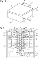
- FIG. 1 illustrates an appearance of a laser unit according to an embodiment of the present invention.
- a laser unit 10 is provided as an independent unit having such a housing 12 as in the drawing when a laser unit 10 is used for applications such as laser processing in a single unit as a DDL.
- a laser emission port 14 is formed in one side surface of the housing 12, and a bundle of combined laser beams SLB T is emitted towards the outside of the unit from the laser emission port 14 when laser is oscillated and output.
- one end of an optical fiber (not illustrated) is attached to the laser emission port 14 via an optical connector (not illustrated).
- Various connectors for connection to an electric cable 16 from a laser power supply (not illustrated), a coolant supply tube 18 from a chiller (not illustrated), and the like are formed on the other side surface of the housing 12.
- a lid 20 which is opened as necessary for maintenance or the like is provided on an upper surface of the housing 12.
- FIG. 2 illustrates major configurations within the laser unit 10 (particularly, an arrangement structure (a layout) of major components) in a plan view.
- FIG. 3 to 6 illustrate a configuration and an operation of respective portions inside the unit 10.
- high heat conductivity for example, copper
- a pair of stacked laser beam creation units 24L and 24R that are bilaterally symmetric relative to a center line N extending in a Y-direction in FIG. 2 are provided on the unit base 22. Furthermore, a single wavelength stabilizing element (for example, VBG 26) of which the incidence plane perpendicularly intersects the center line N, a pair of primary anamorphic prisms 28L and 28R arranged to be separated to left and right sides of the center line N, a mirror-type beam rotation element 30 disposed on the center line N, and a secondary anamorphic prism 32 disposed to be offset in a direction (X-direction) orthogonal to the center line N from the beam rotation element 30 are provided on a downstream side or a rear stage of both of the stacked laser beam creation units 24L and 24R along a travelling direction of a laser beam.
- VBG 26 single wavelength stabilizing element of which the incidence plane perpendicularly intersects the center line N
- the upper surface of the unit base 22 rises in a step form from the side close to the VBG 26 toward the upstream side of the laser beam (a step-shaped LD supporting portion 22a is formed), and a plurality of (seven in the illustrated example) single emitters LDs 36R1, 36R2, ..., and 36R7 are placed on the upper surfaces of the respective steps with an insulator (for example, a ceramic member 34) having high heat conductivity interposed therebetween respectively.
- these single emitters LDs 36R1, 36R2, ..., and 36R7 are arranged in a row at constant intervals d in parallel to the center line N (that is, in the Y-direction).
- these single emitters LDs 36R1, 36R2, ..., and 36R7 are arranged such that the arrangement positions (that is, the height positions of the laser emission surfaces A) differ by a pitch h corresponding to the level difference of the steps.
- Total-reflection mirrors 38R1, 38R2, ..., and 38R7 are arranged on forward sides of the laser emission surfaces A of the single emitters LDs 36R1, 36R2, ..., and 36R7 in such a position that the reflecting surfaces thereof are tilted by 45° in both X- and Y-directions in front of the center line N. That is, the respective mirrors 38Rn are tilted by 45° in the X-direction to face the corresponding single emitters LDs 36Rn and are tilted by 45° in the Y-direction to face the VBG 26.
- the apexes of respective mirrors 38Rn excluding the mirror 38R1 at the highest position in the Z-direction are higher than the laser emission surfaces A of the corresponding single emitter LD 36Rn and are lower than the laser emission surface A of an adjacent single emitter LD 36Rn-1 which is one step higher than the single emitter LD 36Rn.
- a single laser beam LB R1 emitted in the X-direction from the single emitter LD 36R1 at the end disposed at the highest position is incident on the mirror 38R1 at an incidence angle of 45° and is totally reflected at a right angle from the mirror, and as illustrated in part (c) of FIG.3 , travels along a straight line in the Y-direction above the heads of the mirrors 38R2, ..., and 38R7 on the rear stage and is incident on the VBG 26 at the highest position.
- a single laser beam LB R2 emitted in the X-direction from the single emitter LD 36R2 which is the second highest and disposed adjacent to the single emitter LD 36R1 at the end is incident on the mirror LD 38R2 at an incidence angle of 45° and is totally reflected at a right angle from the mirror, and as illustrated in part (c) of FIG. 3 , travels along a straight line in the Y-direction above the heads of the mirrors 38R3, ..., and 38R7 on the rear stage and is incident on the VBG 26 at the second highest position.
- a single laser beam LB R7 emitted in the X-direction from the single emitter LD 36R7 at the other end or a terminal end is incident on the mirror 38R7 at an incidence angle of 45° and is totally reflected at a right angle (that is, in the Y-direction) from the mirror, and as illustrated in part(c) of FIG.3 , is incident on the VBG 26 at the lowest position.
- a fast-axis collimator lens 40Rn and a slow-axis collimator lens 42Rn are disposed on an optical path between the single emitter LD 36Rn and the mirror 38Rn facing each other.
- the fast-axis collimator lens 40Rn is disposed to be adjacent to the laser emission surface A of the single emitter LD 36Rn so as to collimate a beam size of a single laser beam LB Rn immediately after being emitted from the single emitter LD 36Rn in a fast-axis direction.
- the slow-axis collimator lens 42Rn is disposed on a backward side of the fast-axis collimator lens 40Rn as seen from the single emitter LD 36Rn so as to collimate a beam size of the single laser beam LB Rn in a slow-axis direction.
- the single emitters LDs 36R1, 36R2, ..., and 36R7 are single LD chips of the same specifications and are electrically serially connected by an electrode plate or wires (not illustrated) and oscillate and output the single laser beams LB R1 , LB R2 , ..., and LB R7 having a wavelength identical to or proximate to a constant standard wavelength (for example, 880 nm) under DC electric power supplied through the electric cable 16 from a laser power supply.
- a constant standard wavelength for example, 880 nm
- the other stacked laser beam creation unit 24L (on the left side in FIG. 2 ) has the same configuration and function as those of the right-side stacked laser beam creation unit 24R except that the stacked laser beam creation unit 24L is symmetric to the right-side stacked laser beam creation unit 24R with respect to the center line N.
- a plurality of (seven) single laser beams LB L1 , LB L2 , ..., and LB L7 emitted from a plurality of (seven) single emitters LDs 36L1, 36L2, ..., and 36L7 propagate through the air in parallel to the Y-direction in a state of being arranged in the Z-direction in a stacked form and in a non-contacting manner after being reflected from the mirrors 38L1, 38L2, ..., and 38L7, respectively, to form one vertical line of a bundle of first stacked laser beams SLB L as illustrated in FIG. 6A and are incident on the left-side region in FIG. 2 with respect to the center line N of the VBG 26.
- the VBG (Volume Bragg Grating) 26 forms an external resonator and narrows a wavelength width of laser oscillation of the single emitters LDs (36L1, 36L2, ..., and 36L7) and (36R1, 36R2, ..., and 36R7), and suppresses fluctuation in the central wavelength so that the wavelength thereof is locked at a value near the standard wavelength (880 nm).
- VBG Volume Bragg Grating
- VHG Volume Holographic Grating
- the first stacked laser beams SLB L (LB L1 to LB L7 ) and the second stacked laser beams SLB R (LB R1 to LB R7 ) emitted from the VBG 26 are arranged approximately at the same height in the vertical direction (the Z-direction) and are greatly separated in the horizontal direction (the X-direction) by a distance M ( FIG. 4 and 6 ) depending on a spatial margin between the left and right mirrors (38L1 to 38L7) and (38R1 to 38R7) within both stacked laser beam creation units 24L and 24R.
- the first and second stacked laser beams SLB L and SLB R are incident on the left and right primary anamorphic prisms 28L and 28R, respectively.
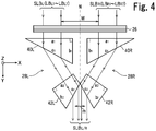
- the right-side primary anamorphic prism 28R is configured with a front-stage right-angle prism 40R which is positioned near the VBG 26 and is disposed so that one (the longer) adjoining side a 1 faces in parallel to the VBG 26 and the other (the shorter) adjoining side b 1 faces in parallel to the center line N, and a rear-stage right-angle prism 42R which is positioned on a backward side of the front-stage right-angle prism 40R in a beam travelling direction (the Y-direction) and is disposed so that one adjoining side a 2 obliquely faces an oblique side c 1 of the front-stage right-angle prism 40R at a certain angle and an oblique side c 2 obliquely faces the center line N at a close distance.
- a front-stage right-angle prism 40R which is positioned near the VBG 26 and is disposed so that one (the longer) adjoining side a 1 faces in parallel to the VBG 26 and the
- the right-side second stacked laser beam SLB R having passed through the VBG 26 in the Y-direction sequentially passes through the front-stage right-angle prism 40R and the rear-stage right-angle prism 42R of the right-side primary anamorphic prism 28R while bending the optical path as illustrated in the drawing and exits in the Y-direction.
- an image size (length) of the individual single laser beams LB R1 to LB R7 that form the second stacked laser beam SLB R is compressed to 1/2 by a predetermined compression ratio of 0.5, for example, in the slow-axis direction ( FIG. 6B to 6C ).
- the optical path of the first stacked laser beam SLB R (LB R1 to LB R7 ) immediately after passing through the rear-stage right-angle prism 42R is shifted greatly in the X-direction so that the optical path almost makes contact with the center line N.
- the left-side primary anamorphic prism 28L has the same configuration as the right-side primary anamorphic prism 28R and both primary anamorphic prisms are disposed line-symmetric relative to the center line N.
- the left-side first stacked laser beam SLB L having passed through the VBG 26 in the Y-direction sequentially passes through front- and rear-stage right-angle prisms 40L and 42L of the left-side primary anamorphic prism 28L along an optical path that is line-symmetric to that of the right-side second stacked laser beam SLB R .
- the image size (length) of the individual single laser beams LB L1 to LB L7 that form the first stacked laser beam SLB L is compressed to 1/2 by a predetermined compression ratio of 0.5, for example part (a) to (c) in FIG. 6 ).
- the optical path of the first stacked laser beam SLB L (LB L1 to LB L7 ) after exiting from the left-side primary anamorphic prism 28L is greatly shifted in the X-direction so that of the optical path almost makes contact with the center line N.
- the combined stacked laser beam SLB L/R passes through the mirror-type beam rotation element 30 in which the pattern or the image of the beam rotates by 90° and the optical path or the travelling direction of the beam is bent at a right angle from the Y-direction to the X-direction.
- the beam rotation element 30 is configured with a pair of total-reflection mirrors 44 and 46 that obliquely face each other in the up-down direction (the Z-direction).
- the front-stage mirror 44 has a reflecting surface 44a formed at a position intersecting the center line N so as to be parallel to the X-direction and be tilted by 45° in the Y-direction, and the front-stage mirror 44 is disposed so that the combined stacked laser beam SLB L/R having passed through the primary anamorphic prisms 28L and 28R is incident on the reflecting surface 44a.
- the rear-stage mirror 46 has a reflecting surface 46a that is parallel to the Y-direction and is tilted by 45° in the X-direction, and the rear-stage mirror 46 is disposed so that the combined stacked laser beam SLB L/R reflected from the reflecting surface 44a of the front-state mirror 44 is incident on the reflecting surface 46a.
- FIG. 5 schematically illustrates a mechanism of how a beam image rotates by 90° and a mechanism of how a beam's optical path is bent at a right angle from the Y-direction to the X-direction with respect to some (two) single laser beams LB Rn-1 and LB Rn of the combined stacked laser beam SLB L/R .
- the rear-stage mirror 46 will be disposed above or below the front-stage mirror 44, and whether the travelling direction (orientation) of the combined stacked laser beam SLB L/R reflected from the rear-stage mirror 46 will be leftward or rightward, and the like can be selected as desired within the range of design matters.
- the mutual positional relation between the first stacked laser beam SLB L and the second stacked laser beam SLB R changes from the previous horizontal two-line relation (in the part (C) of FIG. 6 ) to a vertical two-line relation (in the part (d) of FIG. 6 ).
- the coupling relation of both stacked laser beams SLB L and SLB R is maintained without any change.
- the combined stacked laser beam SLB L/R passes through the secondary anamorphic prism 32 in the X-direction at the rear stage of the beam rotation element 30 in which the image size (thickness) of the individual single laser beams LB L1 to LB L7 and LB R1 to LB R7 that form the combined stacked laser beam SLB L/R is compressed to 1/2 by a predetermined compression ratio of 0.5, for example, in the fast-axis direction (part (d) to (e) of FIG. 6 ). In this case, the space or the interval between the adjacent single laser beams LBs is reduced by the same compression ratio (1/2).
- the travelling direction (the X-direction) of the combined stacked laser beam SLB L/R does not change before the combined stacked laser beam SLB L/R is incident on the secondary anamorphic prism 32 and after the beam passes through the prism, but the optical path is slightly shifted in a horizontal direction (the Y-direction). There is no particular significance to this shift amount.
- the shape and the arrangement positions of the front and rear-stage right-angle prisms 48 and 50 that form the secondary anamorphic prism 32 have no particular limitation like the primary anamorphic prisms 28L and 28R do have ( FIG. 4 ).
- the combined stacked laser beam SLB L/R is output towards the outside of the unit housing 12 from the laser emission port 14 as a combined stacked laser beam SLB T for one unit after passing through the secondary anamorphic prism 32.
- a fiber coupling method one end portion of an optical fiber is attached to the laser emission port 14 via an optical connector, and a condensing lens (not illustrated) is provided between the secondary anamorphic prism 32 and the laser emission port 14.
- the stacked laser beams SLB R and SLB L that form the combined stacked laser beam SLB T and the single laser beams LB L1 to LB L7 and LB R1 to LB R7 are coupled, respectively, during the course of propagating through the optical fiber.
- a plurality of single emitters LDs (36L1 to 36L7 and 36R1 to 36R7) are arranged in a step form while divided into two lines or two sets (36L1 to 36L7) and (36R1 to 36R7), and a plurality of single laser beams (LB L1 to LB L7 ) and (LB R1 to LB R7 ) emitted discretely from these single emitters LDs are individually collimated to form one bundle of stacked laser beams SLB L and SLB R for each set.
- the secondary anamorphic prism 32 narrows the image size or thickness of the individual single laser beams LB L1 to LB L7 and LB R1 to LB R7 that form the combined stacked laser beam SLB L/R and the interval between these single laser beams LBs by a predetermined compression ratio in the fast-axis direction.
- multiplex combination between the combined stacked laser beam SLB T (SLB L/R ) and other combined laser beams of the same type can be performed elaborately and accurately outside the laser unit 10.
- the mirror-type beam rotation element 30 rotates the image of the combined stacked laser beam SLB L/R by 90° and simultaneously bends the beam travelling direction at a right angle, easily understood from FIG. 2 , it is possible to reduce the size of the unit base (heatsink) 22 and the laser unit 10 dramatically in a longitudinal direction (the Y-direction).
- a laser device includes a plurality of the above described laser units 10, and combines a plurality of combined laser beams provided from the respective laser units 10 in a multiplexed manner according to a coupling method to be described later so that a combined laser beam having integer multiples of light-concentration density and laser power is obtained.
- FIG. 7 illustrates a laser device according to a first embodiment.
- This laser device includes two laser units 10(1) and 10(2).
- the unit bases 22(1) and 22(2) of both laser units 10(1) and 10(2) are attached to a common or sole main base (not illustrated) having a flush upper surface.
- the unit housing 12 may be omitted.
- the laser units 10(1) and 10(2) are disposed so that the combined stacked laser beams SLB T1 and SLB T2 having the same standard wavelength (for example, 880 nm) emitted from the respective laser emission ports 14 (1) and 14 (2) intersect each other orthogonally.
- the travelling directions of the first and second combined stacked laser beams SLB T1 and SLB T2 are referred to as Y and X-directions, respectively.
- a spatial coupling element for example, a stripe mirror 52 that forms a transmission portion 52a and a reflection portion 52b which are adjacent to a plate surface tilted by 45° with respect to both of the X and Y-directions is provided at a position at which both combined stacked laser beams SLB T1 and SLB T2 intersect each other.
- the first combined stacked laser beam SLB T1 (LB L1 to LB L7 and LB R1 to LB R7 ) from the first laser unit 10(1) is incident on the transmission portion 52a of the stripe mirror 52 in the X-direction and passes through continuously the transmission portion 52a along a straight line.
- the second combined stacked laser beam SLB T2 (LB L1 to LB L7 and LB R1 to LB R7 ) from the second laser unit 10(2) is incident on the reflection portion 52b of the stripe mirror 52 in the Y-direction and is reflected at a right angle (that is, in the X-direction) from the reflection portion 52b.
- the stripe mirror 52 is configured such that, on a substrate formed of a glass plate, for example, a coating material transmissive to the laser beam SLB T1 is applied to a region corresponding to the transmission portion 52a, and a coating material reflective to the laser beam SLB T2 is applied to a region corresponding to the reflection portion 52b.
- the transmission portion 52a may also be formed as an opening.
- a bundle of multiplexed combined stacked laser beams SLB T1*T2 wherein the first combined stacked laser beam SLB T1 and the second combined stacked laser beam SLB T2 are arranged side by side in the Y-direction is emitted in the X-direction from the stripe mirror 52.
- This multiplexed combined stacked laser beam SLB T1*T2 has light-concentration density and laser power obtained by adding the combined stacked laser beams SLB T1 and SLB T2 having substantially the same wavelength from the laser units 10(1) and 10 (2) .
- This laser device requires high accuracy and stability with regards to optical alignment of the laser units 10(1), 10(2), and the stripe mirror 52 (among three components) in order to enhance spatial coupling accuracy of the multiplexed combined stacked laser beam SLB T1*T2 .
- the long axis of the respective single laser beams LB i and LB j included in the respective combined stacked laser beams SLB T1 and SLB T2 and the stripe of the stripe mirror 52 are both disposed to be orthogonal to a principal surface (the XY plane) of the main base, they are exactly parallel to each other.
- optical alignment can be easily and accurately performed just by adjusting the positions and/or the orientations of the three components 10(1), 10(2), and 52 on the main base plate.
- the respective single laser beams LB i of the first combined stacked laser beam SLB T1 accurately pass through the transmission portion 52a and the respective single laser beams LB j of the second combined stacked laser beam SLB T2 are accurately reflected from the reflection portion 52b.
- the reason why the beam rotation element 30 is provided in the laser unit 10 to rotate the image of the combined stacked laser beam LB L/R by 90° so that the long axes of the respective single laser beams LB i (LB j ) are converted from a horizontal direction to a vertical direction is to cause the combined stacked laser beam LB L/R to be orthogonal to the principal surface (the XY plane) of the main base.
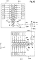
- FIG. 10 illustrates a configuration of a laser device according to a second embodiment.
- This laser device has a similar configuration to the laser device of the first embodiment except that the spatial coupling element 52 is replaced with a polarizing coupling element 54.
- a 1/2 wavelength plate 56 is disposed between the polarizing coupling element 54 and one of the laser units 10(1) and 10(2).
- the polarizing coupling element 54 is configured from a polarizing beam splitter (PBS) for example, and combines orthogonal components of polarized beams of the combined both of stacked laser beams SLB T1 and SLB T2 by this polarization coupling as illustrated in FIG. 11 .
- PBS polarizing beam splitter
- the light-concentration density and the laser power of one bundle of multiplexed combined stacked laser beams SLB T1#T2 obtained by polarization coupling are obtained by adding the combined stacked laser beams SLB T1 and SLB T2 having substantially the same wavelength from the laser units 10(1) and 10(2).
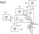
- a laser device includes a larger number of laser units, such as four laser units 10(1), 10(2), 10(3), and 10(4), for example, and is configured to use both the spatial coupling and the polarization coupling described above.
- a bundle of first multiplexed combined stacked laser beams SLB T1*T2 is obtained by spatially coupling both of the combined stacked laser beams SLB T1 and SLB T2 emitted from the laser units 10(1) and 10(2), respectively, by passing the beams through the first spatial coupling element 52.
- a bundle of second multiplexed combined stacked laser beams SLB T3*T4 is obtained by spatially coupling combined stacked laser beams SLB T3 and SLB T4 emitted from the laser units 10(3) and 10(4), respectively, by passing the beams through the second spatial coupling element 52.
- a bundle of multiplied multiplexed combined stacked laser beams SLB T1*T2#T3*T4 (that is, SLB T(1 ⁇ 4) ) is obtained by polarization coupling of the first and second multiplexed combined stacked laser beams SLB T1*T2 and SLB T3*T4 by passing the beams through the 1/2 wavelength plate 56 and the PBS 54.
- FIG. 13A illustrates a coupling relation between the multiplied multiplexed combined stacked laser beam SLB T(1 ⁇ 4) and the respective combined stacked laser beams SLB T1 to SLB T4 .
- the multiplied multiplexed combined stacked laser beam SLB T(1 ⁇ 4) has light-concentration density and laser power that are integer multiples (4 times larger) of those of one laser unit 10, the integer corresponding to the number of the laser units 10 (four in the illustrated example).
- one bundle of multiplied multiplexed combined stacked laser beams SLB T(1 ⁇ 4) obtained from the PBS 54 is input to an optical fiber 60 via an input coupler unit 58 including a condensing lens, propagates through the optical fiber 60, and is delivered to a remote output unit (not illustrated) .
- the multiplied multiplexed combined stacked laser beams SLB T(1 ⁇ 4) output in a single mode from the other end of the optical fiber 60 are condensed and irradiated towards a workpiece and are provided for desired laser processing (for example, welding).
- wavelength coupling may be used together with the spatial coupling and/or the polarization coupling described above.
- Wavelength coupling is a coupling method of combining or multiplexing a plurality of laser beams having different standard wavelengths, exemplary using a dichroic mirror. For example, a multiplied multiplexed combined stacked laser beam SLB T(1 ⁇ 4) obtained by a set of four laser units 10(1) to 10(4) as illustrated in FIG.
- the laser units 10(1) to 10(4) include the above-de scribed wavelength stabilizing element (for example, VBG) 26 and the wavelengths of the combined stacked laser beams SLB T1 to SLB T4 obtained from these laser units 10(1) to 10(4), respectively, are locked at values near the standard wavelengths. Therefore, multiplexed wavelength coupling described above can be performed accurately and stably.
- VBG wavelength stabilizing element
- the laser device of this embodiment with the above-described high-accuracy composite coupling, it is possible to easily and efficiently realize high power of 1kW or more in fiber coupling which uses a narrow optical fiber having a diameter of ⁇ 50 ⁇ m for applications such as DDL, for example.
- the laser unit 10 of the may have three or more stacked laser beam creation units 24 of the above configuration may be mounted on the unit base 22.
- a single VBG 26 and three anamorphic prisms 28A, 28B, and 28C may be used for three sets of stacked laser beams SLB A , SLB B , and SLB C formed by three stacked laser beam creation units 24A, 24B, and 24C (not illustrated), respectively.
- FIG. 14 illustrates a layout.
- two anamorphic prisms 28B and 28C correspond to the two anamorphic prisms 28L and 28R in the embodiment ( FIG. 4 ) and the anamorphic prism 28A at the end (left end) is added thereto in parallel.
- the anamorphic prism 28A is configured with a front-stage right-angle prism 40A which is positioned near the VBG 26 and is disposed so that one (the longer) adjoining side a 1 faces in parallel to the VBG 26 and the other (the shorter) adjoining side b 1 faces in parallel to a virtual reference line K that meets a combined stacked laser beam SL B/C , and a rear-stage right-angle prism 42A which is positioned on the backward side far away from the front-stage right-angle prism 40A in a beam travelling direction (the Y-direction) and is disposed so that one adjoining side a 2 obliquely faces an oblique side c 1 of the front-stage right-angle prism 40A at a certain angle and an oblique side c 2 obliquely faces the merging reference line K at a close distance.
- a front-stage right-angle prism 40A which is positioned near the VBG 26 and is disposed so that one (the longer)
- the optical path of the stacked laser beam SLB A (LB A1 to LB A7 ) immediately after passing through the rear-stage right-angle prism 42A is shifted greatly in the X-direction so that the optical path almost makes contact with the merging reference line K.
- the stacked laser beams SLB B and SLB C are combined in two lines to obtain of combined laser beams SLB B/C to which the stacked laser beam SLB A is added in parallel, whereby a bundle of three lines of combined stacked laser beams SLB A/B/C ( FIG. 15 ) is obtained.
- the compression ratio in the beam's long-axis direction (the slow-axis direction) of the respective anamorphic prisms 28A, 28B, and 28C is set to be 1/3 or smaller.
- a DOVE prism 62 may be used as a modification of the beam rotation element 30 of the laser unit 10 according to the embodiment.
- the combined stacked laser beam SLB L/R having passed through the primary anamorphic prisms 28L and 28R ( FIG. 2 ) in the Y-direction is incident on one inclined end surface of the DOVE prism 62 and then is totally reflected from a bottom surface of the prism 62, and finally exits from one inclined end surface in the Y-direction.
- the pattern or the image of the combined stacked laser beam SLB L/R rotates by 90° before the beam is incident on the DOVE prism 62 and after the beam exits therefrom.
- the DOVE prism 62 When the DOVE prism 62 is used in this manner, since the size of the beam rotation element 30 in the longitudinal direction (the Y-direction) of the laser unit ( FIG. 2 ) increases greatly and the rear-stage secondary anamorphic prism 32 is disposed on an extension line of the Y-direction, the size of the unit base 22 and the entire laser unit 10 tends to increase further. In this regard, the mirror-type beam rotation element 30 ( FIG. 5 ) is advantageous over the DOVE prism 62.
- each of the mirrors 38Ln (38Rn) for reflecting the single laser beams LB Ln (LB Rn ) from the single emitters LDs 36Ln (36Rn) may have (share) the function of the slow-axis collimator lenses 42Ln (42Rn), respectively.
- a single VBG 26 is disposed between the stacked laser beam creation units 24L and 24R and the primary anamorphic prisms 28L and 28R.
- the VBG 26 may be arranged on the optical path after the stacked laser beams SLB L and SLB R pass through the primary anamorphic prisms 28L and 28R (that is, the optical path of the combined stacked laser beam SLB L/R ). According to this arrangement, since the size of the VBG 26 can be reduced to a size that covers one bundle of the combined stacked laser beam SLB L/R , it is possible to further reduce the size and the cost of the VBG 26.
Landscapes
- Physics & Mathematics (AREA)
- General Physics & Mathematics (AREA)
- Optics & Photonics (AREA)
- Condensed Matter Physics & Semiconductors (AREA)
- Electromagnetism (AREA)
- Semiconductor Lasers (AREA)
Abstract
Description
- The present invention relates to a laser unit and a laser device that provide a high-power and high-brightness laser beam using a plurality of single emitters LDs.
- In recent years, in the field of laser processing, there have been many attempts to use a semiconductor laser or a laser diode such as a fiber laser or a YAG laser, which has been used mainly in an excitation light source, directly in a laser processing light source as a direct diode laser (DDL). DDL is roughly divided into that of an array method which uses a combination of a plurality of bar-shaped LD arrays formed monolithically by arranging a plurality of LDs in a horizontal row and that of a single emitter method which uses a combination of a plurality of single LD chips or single emitters LDs. In either system, laser beams emitted simultaneously by a plurality of LDs are combined into a bundle of beams and are usually provided to applications such as laser processing through an optical fiber.
- In the array method, generally a plurality of LD arrays are stacked to form a stacked LD module and provides a bundle of combined laser beams directly from the LD module . This method appears to be an efficient method since laser beams emitted from individual LDs are combined into one bundle immediately after emission. However, in fact, since the emission surface size of the entire LD array or the entire LD module is large, the accuracy of collimation and concentration of the combined laser beams is low. Moreover, since individual beams interfere with each other, coupling efficiency is not so high. Thus, the array method is disadvantageous.
- In contrast, in the single emitter method (for example, see
Non-Patent Documents 1 and 2), a plurality of single emitters LDs are arranged discretely at desired distances, and single laser beams emitted respectively from these single emitters LDs are collimated individually in a fast axis direction and a slow axis direction. Subsequently, the single laser beams are combined into a bundle in a non-contacting manner so as not to cause mutual interference. Therefore, the single emitter method is advantageous in obtaining a high-power and high-brightness laser beam. -
- Non-Patent Document 1: Haro Fritsche et. al., "High Brightness, Direct Diode Laser with kW Output Power," Direct Photonics Industries, 2014
- Non-Patent Document 2: Scott R. Karlsen Fritsche, et. al., "100-W105-µm, 0.15 NA Fiber Coupled Laser Diode Module," nLIGHT, 2009
- However, a conventional laser device which employs the single emitter method combines the collimated individual single laser beams into a bundle without changing the beam size thereof . Therefore, there is a limit to the number or the density of single laser beams included in the combined laser beam. Consequently, there is a limit on the laser power exerted in a DDL and the thinness of the optical fiber used in the fiber coupling method.
- The present invention solves the problems of the conventional technology and an object thereof is to provide a laser unit and a laser device capable of efficiently improving the light-concentration density and the laser power of a bundle of combined laser beams obtained by combining individual laser beams oscillated and output from a plurality of single emitters LDs with high quality.
- A laser unit according to the present invention includes: a first stacked laser beam creation unit that has a plurality of first single emitters LDs disposed in a first direction at a predetermined pitch and at different height positions and that arranges a plurality of first single laser beams having wavelengths identical or proximate to a standard wavelength, emitted respectively from the plurality of first single emitters LDs in a stacked form and in a non-contacting manner to create a bundle of first stacked laser beams; a second stacked laser beam creation unit that is disposed to be adjacent to the first stacked laser beam creation unit and has a plurality of second single emitters LDs disposed in the first direction at the pitch and at different height positions and that arranges a plurality of second single laser beams having wavelengths identical or proximate to the standard wavelength, emitted respectively from the plurality of second single emitters LDs in a stacked form and in a non-contacting manner to create a bundle of second stacked laser beams; a first anamorphic prism that allows the first stacked laser beam from the first stacked laser beam creation unit to pass therethrough so that a beam size of the individual first single laser beams that form the first stacked laser beam is compressed by a first compression ratio in one of a fast-axis direction and a slow-axis direction and an optical path of the first stacked laser beam is shifted toward the second stacked laser beam side; and a second anamorphic prism that allows the second stacked laser beam from the second stacked laser beam creation unit to pass therethrough so that a beam size of the individual second single laser beams that form the second stacked laser beam is compressed by a second compression ratio in the one of the fast-axis direction and the slow-axis direction and an optical path of the second stacked laser beam is shifted toward the first stacked laser beam side, wherein the laser unit provides a bundle of combined stacked laser beams obtained by combining the first stacked laser beam and the second stacked laser beam in parallel.
- In the laser unit having the above-described configuration, during the course in which two bundles of stacked laser beams respectively obtained from the two sets of single emitters LDs pass through the first and second anamorphic prisms, the image size of the single laser beams that form both of the stacked laser beams is compressed and, simultaneously, both of the stacked laser beams approach each other. In this way, two lines of bundles of high-density laser beams are combined. Therefore, it is possible to improve the light-concentration density and the laser power of the laser beam with high quality.
- A first laser device according to the present invention includes : the first laser unit according to the present invention that emits a first combined stacked laser beam in a fourth direction orthogonal to the first direction; the second laser unit according to the present invention that emits a second combined stacked laser beam in a fifth direction orthogonal to the first and fourth directions; and a spatial coupling element that has a transmission portion and a reflection portion arranged to be adjacent to each other in a direction inclined by 45° with respect to the fourth and fifth directions, the spatial coupling element allowing the first combined stacked laser beam from the first laser unit and the second combined stacked laser beam from the second laser unit to be selectively incident on the transmission portion or the reflection portion to combine the first combined stacked laser beam and the second combined stacked laser beam into a bundle of laser beams in a multiplexed manner and in a non-contacting manner.
- Since the laser device having the above-described configuration further combines a plurality of combined stacked laser beams obtained respectively from the present invention laser units of the present invention in a multiplexed manner by spatial coupling, it is possible to further increase the laser power with high quality.
- A second laser device according to the present invention includes : the first laser unit according to the present invention that emits a first combined stacked laser beam in a fourth direction orthogonal to the first direction; the second laser unit according to the present invention that emits a second combined stacked laser beam in a fifth direction orthogonal to both the first and fourth directions; and a polarizing coupling element that combines the first combined stacked laser beam from the first laser unit and the second combined stacked laser beam from the second laser unit into a bundle of laser beams in a multiplexed manner by polarization coupling.
- Since the laser device having the above-described configuration further combines a plurality of combined stacked laser beams obtained from a plurality of the laser units of the present invention in a multiplexed manner by polarization coupling, it is possible to further increase the laser power with high quality.
- A third laser device according to the present invention includes : the first laser unit according to claim 5 or the present invention that emits a first combined stacked laser beam having a wavelength near a first standard wavelength in a fourth direction orthogonal to the first direction; the second laser unit according to the present invention that emits a second combined stacked laser beam having a wavelength near a second standard wavelength that does not interfere with the first standard wavelength in a fifth direction orthogonal to the first and fourth directions; and a wavelength coupling element that combines the first combined stacked laser beam from the first laser unit and the second combined stacked laser beam from the second laser unit into a bundle of laser beams in a multiplexed manner by wavelength coupling.
- Since the laser device having the above-described configuration further combines a plurality of combined stacked laser beams respectively obtained from a plurality of the laser units of the present invention in a multiplexed manner by wavelength coupling, it is possible to further increase the laser power with high quality.
- According to the laser unit or the laser device of the present invention, due to the above-described configuration and operation, it is possible to efficiently improve the light-concentration density and the laser power of a bundle of combined laser beams obtained by combining single laser beams oscillated and output from a plurality of single emitters LDs with high accuracy.
-
-
FIG. 1 is a perspective view illustrating an outer configuration of a laser unit according to an embodiment of the present invention. -
FIG. 2 is a plan view illustrating major configurations inside the laser unit. -
FIG. 3 is a plan view illustrating configurations and operations of major portions of a stacked laser beam creation unit of the laser unit. -
FIG. 4 is a plan view illustrating a configuration and an operation of a primary anamorphic prism of the laser unit. -
FIG. 5 is a plan view illustrating a configuration and an operation of a beam rotation element of the laser unit. -
FIG. 6 is a diagram illustrating patterns (images) of laser beams of respective major portions of the laser unit. -
FIG. 7 is a schematic plan view illustrating a configuration of a laser device according to a first embodiment. -
FIG. 8 is a perspective view illustrating a configuration and an operation of a stripe mirror (a spatial coupling element) provided in the laser device illustrated inFIG. 7 . -
FIG. 9 is a diagram illustrating patterns (images) of laser beams in respective portions of the laser device illustrated inFIG. 7 . -
FIG. 10 is a schematic plan view illustrating a configuration of a laser device according to a second embodiment. -
FIG. 11 is a diagram illustrating patterns (images) of laser beams in respective portions of the laser device illustrated inFIG. 10 . -
FIG. 12 is a schematic plan view illustrating a configuration of a laser device according to a third embodiment. -
FIG. 13A is a diagram illustrating patterns (images) of laser beams in respective portions of the laser device illustrated inFIG. 12 . -
FIG. 13B is a diagram illustrating patterns (images) of laser beams in respective portions of a laser device according to another embodiment. -
FIG. 14 is a diagram illustrating a modification of a primary anamorphic prism assembly according to an embodiment. -
FIG. 15 is a diagram illustrating patterns (images) of laser beams in respective portions of the anamorphic prism assembly illustrated inFIG. 14 . -
FIG. 16 is a diagram illustrating another configuration example of a beam rotation element. -
FIG. 17 is a plan view illustrating an example of an arrangement configuration of wavelength stabilizing elements. - Hereinafter, preferred embodiments of the present invention will be described with reference to the accompanying drawings.
-
FIG. 1 illustrates an appearance of a laser unit according to an embodiment of the present invention. Alaser unit 10 is provided as an independent unit having such ahousing 12 as in the drawing when alaser unit 10 is used for applications such as laser processing in a single unit as a DDL. Alaser emission port 14 is formed in one side surface of thehousing 12, and a bundle of combined laser beams SLBT is emitted towards the outside of the unit from thelaser emission port 14 when laser is oscillated and output. When a fiber coupling method is employed, one end of an optical fiber (not illustrated) is attached to thelaser emission port 14 via an optical connector (not illustrated). Various connectors (not illustrated) for connection to anelectric cable 16 from a laser power supply (not illustrated), acoolant supply tube 18 from a chiller (not illustrated), and the like are formed on the other side surface of thehousing 12. Alid 20 which is opened as necessary for maintenance or the like is provided on an upper surface of thehousing 12. -
FIG. 2 illustrates major configurations within the laser unit 10 (particularly, an arrangement structure (a layout) of major components) in a plan view.FIG. 3 to 6 illustrate a configuration and an operation of respective portions inside theunit 10. - A
planar unit base 22 formed of a member having high heat conductivity (for example, copper) which is mounted with and supports all components in the unit and functions as a heatsink is disposed at the bottom of thelaser unit 10. Passages (not illustrated) through which the coolant supplied via thecoolant supply tube 18 travels to respective portions are formed inside theunit base 22. - A pair of stacked laser
beam creation units FIG. 2 are provided on theunit base 22. Furthermore, a single wavelength stabilizing element (for example, VBG 26) of which the incidence plane perpendicularly intersects the center line N, a pair of primaryanamorphic prisms beam rotation element 30 disposed on the center line N, and a secondaryanamorphic prism 32 disposed to be offset in a direction (X-direction) orthogonal to the center line N from thebeam rotation element 30 are provided on a downstream side or a rear stage of both of the stacked laserbeam creation units - In one stacked laser
beam creation unit 24R (on the right side inFIG. 2 ), as illustrated in part (b) ofFig.3 , the upper surface of theunit base 22 rises in a step form from the side close to theVBG 26 toward the upstream side of the laser beam (a step-shapedLD supporting portion 22a is formed), and a plurality of (seven in the illustrated example) single emitters LDs 36R1, 36R2, ..., and 36R7 are placed on the upper surfaces of the respective steps with an insulator (for example, a ceramic member 34) having high heat conductivity interposed therebetween respectively. Here, each of the single emitters LDs 36Rn (n=1, 2, ..., 7) are disposed so that the laser emission surface A thereof faces the center line N (that is, the X-direction). - When the bottom surfaces of the
laser unit 10 and theunit base plate 22 are seen in a plan view as the XY plane, as illustrated inFIG. 2 and part (a) ofFIG. 3 , these single emitters LDs 36R1, 36R2, ..., and 36R7 are arranged in a row at constant intervals d in parallel to the center line N (that is, in the Y-direction). Moreover, in a unit height direction (that is, the Z-direction) perpendicular to the XY plane, as illustrated in part (b) ofFIG. 3 , these single emitters LDs 36R1, 36R2, ..., and 36R7 are arranged such that the arrangement positions (that is, the height positions of the laser emission surfaces A) differ by a pitch h corresponding to the level difference of the steps. - Total-reflection mirrors 38R1, 38R2, ..., and 38R7 are arranged on forward sides of the laser emission surfaces A of the single emitters LDs 36R1, 36R2, ..., and 36R7 in such a position that the reflecting surfaces thereof are tilted by 45° in both X- and Y-directions in front of the center line N. That is, the respective mirrors 38Rn are tilted by 45° in the X-direction to face the corresponding single emitters LDs 36Rn and are tilted by 45° in the Y-direction to face the
VBG 26. - Here, the apexes of respective mirrors 38Rn excluding the mirror 38R1 at the highest position in the Z-direction are higher than the laser emission surfaces A of the corresponding single emitter LD 36Rn and are lower than the laser emission surface A of an adjacent single emitter LD 36Rn-1 which is one step higher than the single emitter LD 36Rn. According to such an arrangement, a single laser beam LBR1 emitted in the X-direction from the single emitter LD 36R1 at the end disposed at the highest position is incident on the mirror 38R1 at an incidence angle of 45° and is totally reflected at a right angle from the mirror, and as illustrated in part (c) of
FIG.3 , travels along a straight line in the Y-direction above the heads of the mirrors 38R2, ..., and 38R7 on the rear stage and is incident on theVBG 26 at the highest position. - Moreover, a single laser beam LBR2 emitted in the X-direction from the single emitter LD 36R2 which is the second highest and disposed adjacent to the single emitter LD 36R1 at the end is incident on the mirror LD 38R2 at an incidence angle of 45° and is totally reflected at a right angle from the mirror, and as illustrated in part (c) of
FIG. 3 , travels along a straight line in the Y-direction above the heads of the mirrors 38R3, ..., and 38R7 on the rear stage and is incident on theVBG 26 at the second highest position. Moreover, a single laser beam LBR7 emitted in the X-direction from the single emitter LD 36R7 at the other end or a terminal end is incident on the mirror 38R7 at an incidence angle of 45° and is totally reflected at a right angle (that is, in the Y-direction) from the mirror, and as illustrated in part(c) ofFIG.3 , is incident on theVBG 26 at the lowest position. - A fast-axis collimator lens 40Rn and a slow-axis collimator lens 42Rn are disposed on an optical path between the single emitter LD 36Rn and the mirror 38Rn facing each other. The fast-axis collimator lens 40Rn is disposed to be adjacent to the laser emission surface A of the single emitter LD 36Rn so as to collimate a beam size of a single laser beam LBRn immediately after being emitted from the single emitter LD 36Rn in a fast-axis direction. Moreover, the slow-axis collimator lens 42Rn is disposed on a backward side of the fast-axis collimator lens 40Rn as seen from the single emitter LD 36Rn so as to collimate a beam size of the single laser beam LBRn in a slow-axis direction.
- In the right-side stacked laser
beam creation unit 24R having the above-described configuration, as illustrated inFIG. 2 , part (a) and (c) ofFIG. 3 , a plurality of (seven) single laser beams LBR1, LBR2, ..., and LBR7 emitted from the plurality of single emitters LDs 36R1, 36R2, ..., and 36R7, respectively, propagate through the air in parallel to the Y-direction while being arranged in the Z-direction in a stacked form and in a non-contacting manner after being reflected from the mirrors 38R1, 38R2, ..., and 38R7 to form one vertical line of a bundle of second stacked laser beams SLBR as illustrated in part(b) ofFIG. 6 and are incident on the right-side region ofFIG. 2 with respect to the center line N of theVBG 26. - The single emitters LDs 36R1, 36R2, ..., and 36R7 are single LD chips of the same specifications and are electrically serially connected by an electrode plate or wires (not illustrated) and oscillate and output the single laser beams LBR1, LBR2, ..., and LBR7 having a wavelength identical to or proximate to a constant standard wavelength (for example, 880 nm) under DC electric power supplied through the
electric cable 16 from a laser power supply. - The other stacked laser
beam creation unit 24L (on the left side inFIG. 2 ) has the same configuration and function as those of the right-side stacked laserbeam creation unit 24R except that the stacked laserbeam creation unit 24L is symmetric to the right-side stacked laserbeam creation unit 24R with respect to the center line N. Therefore, in the left-side stacked laserbeam creation unit 24L, a plurality of (seven) single laser beams LBL1, LBL2, ..., and LBL7 emitted from a plurality of (seven) single emitters LDs 36L1, 36L2, ..., and 36L7 propagate through the air in parallel to the Y-direction in a state of being arranged in the Z-direction in a stacked form and in a non-contacting manner after being reflected from the mirrors 38L1, 38L2, ..., and 38L7, respectively, to form one vertical line of a bundle of first stacked laser beams SLBL as illustrated inFIG. 6A and are incident on the left-side region inFIG. 2 with respect to the center line N of theVBG 26. - The VBG (Volume Bragg Grating) 26 forms an external resonator and narrows a wavelength width of laser oscillation of the single emitters LDs (36L1, 36L2, ..., and 36L7) and (36R1, 36R2, ..., and 36R7), and suppresses fluctuation in the central wavelength so that the wavelength thereof is locked at a value near the standard wavelength (880 nm). In this embodiment, since the sole or
single VBG 26 is shared by all single emitters LDs in the unit, it is possible to reduce the cost and, in addition, the accuracy of the bandwidth narrowing and the wavelength locking is stable. VHG (Volume Holographic Grating) can be also used as the wavelength stabilizing element. - The first stacked laser beams SLBL (LBL1 to LBL7) and the second stacked laser beams SLBR (LBR1 to LBR7) emitted from the
VBG 26 are arranged approximately at the same height in the vertical direction (the Z-direction) and are greatly separated in the horizontal direction (the X-direction) by a distance M (FIG. 4 and6 ) depending on a spatial margin between the left and right mirrors (38L1 to 38L7) and (38R1 to 38R7) within both stacked laserbeam creation units anamorphic prisms - As illustrated in
FIG. 4 , the right-side primaryanamorphic prism 28R is configured with a front-stage right-angle prism 40R which is positioned near theVBG 26 and is disposed so that one (the longer) adjoining side a1 faces in parallel to theVBG 26 and the other (the shorter) adjoining side b1 faces in parallel to the center line N, and a rear-stage right-angle prism 42R which is positioned on a backward side of the front-stage right-angle prism 40R in a beam travelling direction (the Y-direction) and is disposed so that one adjoining side a2 obliquely faces an oblique side c1 of the front-stage right-angle prism 40R at a certain angle and an oblique side c2 obliquely faces the center line N at a close distance. - The right-side second stacked laser beam SLBR having passed through the
VBG 26 in the Y-direction sequentially passes through the front-stage right-angle prism 40R and the rear-stage right-angle prism 42R of the right-side primaryanamorphic prism 28R while bending the optical path as illustrated in the drawing and exits in the Y-direction. In this case, an image size (length) of the individual single laser beams LBR1 to LBR7 that form the second stacked laser beam SLBR is compressed to 1/2 by a predetermined compression ratio of 0.5, for example, in the slow-axis direction (FIG. 6B to 6C ). - Furthermore, since a large part of the corner portion between the adjoining side a2 and the oblique side c2 of the rear-stage right-
angle prism 42R is cut off, and the oblique side c2 is brought close to the center line N as much as possible, the optical path of the first stacked laser beam SLBR (LBR1 to LBR7) immediately after passing through the rear-stage right-angle prism 42R is shifted greatly in the X-direction so that the optical path almost makes contact with the center line N. - The left-side primary
anamorphic prism 28L has the same configuration as the right-side primaryanamorphic prism 28R and both primary anamorphic prisms are disposed line-symmetric relative to the center line N. The left-side first stacked laser beam SLBL having passed through theVBG 26 in the Y-direction sequentially passes through front- and rear-stage right-angle prisms anamorphic prism 28L along an optical path that is line-symmetric to that of the right-side second stacked laser beam SLBR. - According to such an arrangement, the image size (length) of the individual single laser beams LBL1 to LBL7 that form the first stacked laser beam SLBL is compressed to 1/2 by a predetermined compression ratio of 0.5, for example part (a) to (c) in
FIG. 6 ). The optical path of the first stacked laser beam SLBL (LBL1 to LBL7) after exiting from the left-side primaryanamorphic prism 28L is greatly shifted in the X-direction so that of the optical path almost makes contact with the center line N. - In this way, on the rear stage of the pair of left and right-side primary
anamorphic prisms FIG. 6 , a bundle of combined stacked laser beams SLBL/R wherein the first stacked laser beam SLBL and the second stacked laser beam SLBR are arranged in two horizontal lines with a very small gap 'm' interposed therebetween is obtained. - As illustrated in
FIG. 2 , the combined stacked laser beam SLBL/R passes through the mirror-typebeam rotation element 30 in which the pattern or the image of the beam rotates by 90° and the optical path or the travelling direction of the beam is bent at a right angle from the Y-direction to the X-direction. - As illustrated in
FIG. 5 , thebeam rotation element 30 is configured with a pair of total-reflection mirrors 44 and 46 that obliquely face each other in the up-down direction (the Z-direction). Here, the front-stage mirror 44 has a reflectingsurface 44a formed at a position intersecting the center line N so as to be parallel to the X-direction and be tilted by 45° in the Y-direction, and the front-stage mirror 44 is disposed so that the combined stacked laser beam SLBL/R having passed through the primaryanamorphic prisms surface 44a. The rear-stage mirror 46 has a reflectingsurface 46a that is parallel to the Y-direction and is tilted by 45° in the X-direction, and the rear-stage mirror 46 is disposed so that the combined stacked laser beam SLBL/R reflected from the reflectingsurface 44a of the front-state mirror 44 is incident on the reflectingsurface 46a. -
FIG. 5 schematically illustrates a mechanism of how a beam image rotates by 90° and a mechanism of how a beam's optical path is bent at a right angle from the Y-direction to the X-direction with respect to some (two) single laser beams LBRn-1 and LBRn of the combined stacked laser beam SLBL/R. Whether the rear-stage mirror 46 will be disposed above or below the front-stage mirror 44, and whether the travelling direction (orientation) of the combined stacked laser beam SLBL/R reflected from the rear-stage mirror 46 will be leftward or rightward, and the like can be selected as desired within the range of design matters. - In this way, when the image of the combined stacked laser beam SLBL/R is rotated by 90° by the
beam rotation element 30, the mutual positional relation between the first stacked laser beam SLBL and the second stacked laser beam SLBR changes from the previous horizontal two-line relation (in the part (C) ofFIG. 6 ) to a vertical two-line relation (in the part (d) ofFIG. 6 ). However, the coupling relation of both stacked laser beams SLBL and SLBR is maintained without any change. - Subsequently, the combined stacked laser beam SLBL/Rpasses through the secondary
anamorphic prism 32 in the X-direction at the rear stage of thebeam rotation element 30 in which the image size (thickness) of the individual single laser beams LBL1 to LBL7 and LBR1 to LBR7 that form the combined stacked laser beam SLBL/R is compressed to 1/2 by a predetermined compression ratio of 0.5, for example, in the fast-axis direction (part (d) to (e) ofFIG. 6 ). In this case, the space or the interval between the adjacent single laser beams LBs is reduced by the same compression ratio (1/2). - The travelling direction (the X-direction) of the combined stacked laser beam SLBL/R does not change before the combined stacked laser beam SLBL/R is incident on the secondary
anamorphic prism 32 and after the beam passes through the prism, but the optical path is slightly shifted in a horizontal direction (the Y-direction). There is no particular significance to this shift amount. In addition, the shape and the arrangement positions of the front and rear-stage right-angle prisms anamorphic prism 32 have no particular limitation like the primaryanamorphic prisms FIG. 4 ). - The combined stacked laser beam SLBL/R is output towards the outside of the
unit housing 12 from thelaser emission port 14 as a combined stacked laser beam SLBT for one unit after passing through the secondaryanamorphic prism 32. When a fiber coupling method is employed, one end portion of an optical fiber is attached to thelaser emission port 14 via an optical connector, and a condensing lens (not illustrated) is provided between the secondaryanamorphic prism 32 and thelaser emission port 14. When the combined stacked laser beam SLBT is incident on the optical fiber, the stacked laser beams SLBR and SLBL that form the combined stacked laser beam SLBT and the single laser beams LBL1 to LBL7 and LBR1 to LBR7 are coupled, respectively, during the course of propagating through the optical fiber. - As described above, according to the
laser unit 10 of this embodiment, in a pair of stacked laserbeam creation units anamorphic prisms - In this
laser unit 10, since all components of both stacked laserbeam creation units same unit base 22 having a heatsink function, the positional accuracy of and between the respective optical components is very high and stable. Moreover, the relative positional relational accuracy between the single laser beams (LBL1 to LBL7 and LBR1 to LBR7) and between the stacked laser beams SLBL and SLBR is high and stable. Therefore, it is possible to reliably avoid mutual interference between the single laser beams and between the stacked laser beams in the combined laser beam SLBL/R and to obtain a high-density and high-quality combined stacked laser beam SLBL/R. - Furthermore, in this embodiment, the secondary
anamorphic prism 32 narrows the image size or thickness of the individual single laser beams LBL1 to LBL7 and LBR1 to LBR7 that form the combined stacked laser beam SLBL/R and the interval between these single laser beams LBs by a predetermined compression ratio in the fast-axis direction. In this way, as will be described later, multiplex combination between the combined stacked laser beam SLBT (SLBL/R) and other combined laser beams of the same type can be performed elaborately and accurately outside thelaser unit 10. - Moreover, in this embodiment, since the mirror-type
beam rotation element 30 rotates the image of the combined stacked laser beam SLBL/R by 90° and simultaneously bends the beam travelling direction at a right angle, easily understood fromFIG. 2 , it is possible to reduce the size of the unit base (heatsink) 22 and thelaser unit 10 dramatically in a longitudinal direction (the Y-direction). - Hereinafter, an embodiment of a laser device according to the present invention will be described with reference to
FIG. 7 to 14 . - A laser device according to an embodiment of the present invention includes a plurality of the above described
laser units 10, and combines a plurality of combined laser beams provided from therespective laser units 10 in a multiplexed manner according to a coupling method to be described later so that a combined laser beam having integer multiples of light-concentration density and laser power is obtained. -
FIG. 7 illustrates a laser device according to a first embodiment. This laser device includes two laser units 10(1) and 10(2). Here, the unit bases 22(1) and 22(2) of both laser units 10(1) and 10(2) are attached to a common or sole main base (not illustrated) having a flush upper surface. Theunit housing 12 may be omitted. However, the laser units 10(1) and 10(2) are disposed so that the combined stacked laser beams SLBT1 and SLBT2 having the same standard wavelength (for example, 880 nm) emitted from the respective laser emission ports 14 (1) and 14 (2) intersect each other orthogonally. In this example, the travelling directions of the first and second combined stacked laser beams SLBT1 and SLBT2 are referred to as Y and X-directions, respectively. - More specifically, as illustrated in
FIG. 8 , a spatial coupling element (for example, a stripe mirror 52) that forms atransmission portion 52a and areflection portion 52b which are adjacent to a plate surface tilted by 45° with respect to both of the X and Y-directions is provided at a position at which both combined stacked laser beams SLBT1 and SLBT2 intersect each other. The first combined stacked laser beam SLBT1 (LBL1 to LBL7 and LBR1 to LBR7) from the first laser unit 10(1) is incident on thetransmission portion 52a of thestripe mirror 52 in the X-direction and passes through continuously thetransmission portion 52a along a straight line. On the other hand, the second combined stacked laser beam SLBT2 (LBL1 to LBL7 and LBR1 to LBR7) from the second laser unit 10(2) is incident on thereflection portion 52b of thestripe mirror 52 in the Y-direction and is reflected at a right angle (that is, in the X-direction) from thereflection portion 52b. Thestripe mirror 52 is configured such that, on a substrate formed of a glass plate, for example, a coating material transmissive to the laser beam SLBT1 is applied to a region corresponding to thetransmission portion 52a, and a coating material reflective to the laser beam SLBT2 is applied to a region corresponding to thereflection portion 52b. Thetransmission portion 52a may also be formed as an opening. - In this way, as illustrated in
FIG. 9 , a bundle of multiplexed combined stacked laser beams SLBT1*T2 wherein the first combined stacked laser beam SLBT1 and the second combined stacked laser beam SLBT2 are arranged side by side in the Y-direction is emitted in the X-direction from thestripe mirror 52. This multiplexed combined stacked laser beam SLBT1*T2 has light-concentration density and laser power obtained by adding the combined stacked laser beams SLBT1 and SLBT2 having substantially the same wavelength from the laser units 10(1) and 10 (2) . - This laser device requires high accuracy and stability with regards to optical alignment of the laser units 10(1), 10(2), and the stripe mirror 52 (among three components) in order to enhance spatial coupling accuracy of the multiplexed combined stacked laser beam SLBT1*T2. In this embodiment, since the long axis of the respective single laser beams LBi and LBj included in the respective combined stacked laser beams SLBT1 and SLBT2 and the stripe of the
stripe mirror 52 are both disposed to be orthogonal to a principal surface (the XY plane) of the main base, they are exactly parallel to each other. Hence, optical alignment can be easily and accurately performed just by adjusting the positions and/or the orientations of the three components 10(1), 10(2), and 52 on the main base plate. According to such an arrangement, in thestripe mirror 52, the respective single laser beams LBi of the first combined stacked laser beam SLBT1 accurately pass through thetransmission portion 52a and the respective single laser beams LBj of the second combined stacked laser beam SLBT2 are accurately reflected from thereflection portion 52b. The reason why thebeam rotation element 30 is provided in thelaser unit 10 to rotate the image of the combined stacked laser beam LBL/R by 90° so that the long axes of the respective single laser beams LBi (LBj) are converted from a horizontal direction to a vertical direction is to cause the combined stacked laser beam LBL/R to be orthogonal to the principal surface (the XY plane) of the main base. -
FIG. 10 illustrates a configuration of a laser device according to a second embodiment. This laser device has a similar configuration to the laser device of the first embodiment except that thespatial coupling element 52 is replaced with apolarizing coupling element 54. A 1/2wavelength plate 56 is disposed between thepolarizing coupling element 54 and one of the laser units 10(1) and 10(2). Thepolarizing coupling element 54 is configured from a polarizing beam splitter (PBS) for example, and combines orthogonal components of polarized beams of the combined both of stacked laser beams SLBT1 and SLBT2 by this polarization coupling as illustrated inFIG. 11 . The light-concentration density and the laser power of one bundle of multiplexed combined stacked laser beams SLBT1#T2 obtained by polarization coupling are obtained by adding the combined stacked laser beams SLBT1 and SLBT2 having substantially the same wavelength from the laser units 10(1) and 10(2). - A laser device according to a third embodiment illustrated in
FIG. 12 includes a larger number of laser units, such as four laser units 10(1), 10(2), 10(3), and 10(4), for example, and is configured to use both the spatial coupling and the polarization coupling described above. - Here, a bundle of first multiplexed combined stacked laser beams SLBT1*T2 is obtained by spatially coupling both of the combined stacked laser beams SLBT1 and SLBT2 emitted from the laser units 10(1) and 10(2), respectively, by passing the beams through the first
spatial coupling element 52. On the other hand, a bundle of second multiplexed combined stacked laser beams SLBT3*T4 is obtained by spatially coupling combined stacked laser beams SLBT3 and SLBT4 emitted from the laser units 10(3) and 10(4), respectively, by passing the beams through the secondspatial coupling element 52. Moreover, a bundle of multiplied multiplexed combined stacked laser beams SLBT1*T2#T3*T4 (that is, SLBT(1∼4)) is obtained by polarization coupling of the first and second multiplexed combined stacked laser beams SLBT1*T2 and SLBT3*T4 by passing the beams through the 1/2wavelength plate 56 and thePBS 54.FIG. 13A illustrates a coupling relation between the multiplied multiplexed combined stacked laser beam SLBT(1∼4) and the respective combined stacked laser beams SLBT1 to SLBT4. - If the laser units 10 (1) to 10 (4) have similar wavelength and power, the multiplied multiplexed combined stacked laser beam SLBT(1∼4) has light-concentration density and laser power that are integer multiples (4 times larger) of those of one
laser unit 10, the integer corresponding to the number of the laser units 10 (four in the illustrated example). - In
FIG. 12 , one bundle of multiplied multiplexed combined stacked laser beams SLBT(1∼4) obtained from thePBS 54 is input to anoptical fiber 60 via aninput coupler unit 58 including a condensing lens, propagates through theoptical fiber 60, and is delivered to a remote output unit (not illustrated) . In the output unit, the multiplied multiplexed combined stacked laser beams SLBT(1∼4) output in a single mode from the other end of theoptical fiber 60 are condensed and irradiated towards a workpiece and are provided for desired laser processing (for example, welding). - In another embodiment, wavelength coupling may be used together with the spatial coupling and/or the polarization coupling described above. Wavelength coupling is a coupling method of combining or multiplexing a plurality of laser beams having different standard wavelengths, exemplary using a dichroic mirror. For example, a multiplied multiplexed combined stacked laser beam SLBT(1∼4) obtained by a set of four laser units 10(1) to 10(4) as illustrated in
FIG. 12 having a first standard wavelength (for example, 880 µm) and a multiplied multiplexed combined stacked laser beam SLBT(1∼4) obtained by another set of four laser units 10(1) to 10(4) having a second standard wavelength (for example, 915 µm) are multiplexed and combined by two-wavelength coupling as illustrated in part (a) ofFIG. 13B to obtain a bundle of multiplexed combined stacked laser beams SLBT2(1∼4). In this way, it is possible to further increase the laser power two times. By the same principle, by using other laser beams of other standard wavelengths such as 940 µm, 960 µm, and 975 µm, for example, it is also possible to obtain a multiplexed combined stacked laser beam SLBT3(1∼4) of three-wavelength coupling as illustrated in part (b) ofFIG. 13B or a multiplexed combined stacked laser beam SLBT4(1∼4) of four-wavelength coupling as illustrated in part (c) ofFIG. 13B . In this way, laser power can easily be increased three times, four times, or more. Moreover, in this embodiment, since the laser units 10(1) to 10(4) include the above-de scribed wavelength stabilizing element (for example, VBG) 26 and the wavelengths of the combined stacked laser beams SLBT1 to SLBT4 obtained from these laser units 10(1) to 10(4), respectively, are locked at values near the standard wavelengths. Therefore, multiplexed wavelength coupling described above can be performed accurately and stably. - According to the laser device of this embodiment, with the above-described high-accuracy composite coupling, it is possible to easily and efficiently realize high power of 1kW or more in fiber coupling which uses a narrow optical fiber having a diameter of Φ50 µm for applications such as DDL, for example.
- In this embodiment, the
laser unit 10 of the may have three or more stacked laserbeam creation units 24 of the above configuration may be mounted on theunit base 22. In this case, for example, asingle VBG 26 and threeanamorphic prisms FIG. 14 illustrates a layout. - That is, two
anamorphic prisms anamorphic prisms FIG. 4 ) and theanamorphic prism 28A at the end (left end) is added thereto in parallel. Here, theanamorphic prism 28A is configured with a front-stage right-angle prism 40A which is positioned near theVBG 26 and is disposed so that one (the longer) adjoining side a1 faces in parallel to theVBG 26 and the other (the shorter) adjoining side b1 faces in parallel to a virtual reference line K that meets a combined stacked laser beam SLB/C, and a rear-stage right-angle prism 42A which is positioned on the backward side far away from the front-stage right-angle prism 40A in a beam travelling direction (the Y-direction) and is disposed so that one adjoining side a2 obliquely faces an oblique side c1 of the front-stage right-angle prism 40A at a certain angle and an oblique side c2 obliquely faces the merging reference line K at a close distance. Here, since a large part of the corner portion between the adjoining side a2 and the oblique side c2 of the rear-stage right-angle prism 42A is cut off, and the oblique side c2 is brought close to the merging reference line K as much as possible, the optical path of the stacked laser beam SLBA (LBA1 to LBA7) immediately after passing through the rear-stage right-angle prism 42A is shifted greatly in the X-direction so that the optical path almost makes contact with the merging reference line K. - In this way, the stacked laser beams SLBB and SLBC are combined in two lines to obtain of combined laser beams SLBB/C to which the stacked laser beam SLBA is added in parallel, whereby a bundle of three lines of combined stacked laser beams SLBA/B/C (
FIG. 15 ) is obtained. - When three independent bundles of stacked laser beams SLBA, SLBB, and SLBC are combined in three lines to obtain a bundle of combined stacked laser beams SLBA/B/C, it is preferable that the compression ratio in the beam's long-axis direction (the slow-axis direction) of the respective
anamorphic prisms - Moreover, as illustrated in
FIG. 16 , aDOVE prism 62 may be used as a modification of thebeam rotation element 30 of thelaser unit 10 according to the embodiment. In this case, the combined stacked laser beam SLBL/R having passed through the primaryanamorphic prisms FIG. 2 ) in the Y-direction is incident on one inclined end surface of theDOVE prism 62 and then is totally reflected from a bottom surface of theprism 62, and finally exits from one inclined end surface in the Y-direction. In this case, the pattern or the image of the combined stacked laser beam SLBL/R rotates by 90° before the beam is incident on theDOVE prism 62 and after the beam exits therefrom. - When the
DOVE prism 62 is used in this manner, since the size of thebeam rotation element 30 in the longitudinal direction (the Y-direction) of the laser unit (FIG. 2 ) increases greatly and the rear-stage secondaryanamorphic prism 32 is disposed on an extension line of the Y-direction, the size of theunit base 22 and theentire laser unit 10 tends to increase further. In this regard, the mirror-type beam rotation element 30 (FIG. 5 ) is advantageous over theDOVE prism 62. - Moreover, in the
laser unit 10 according to the embodiment, each of the mirrors 38Ln (38Rn) for reflecting the single laser beams LBLn (LBRn) from the single emitters LDs 36Ln (36Rn) may have (share) the function of the slow-axis collimator lenses 42Ln (42Rn), respectively. - In the above embodiment, a
single VBG 26 is disposed between the stacked laserbeam creation units anamorphic prisms FIG. 17 , theVBG 26 may be arranged on the optical path after the stacked laser beams SLBL and SLBR pass through the primaryanamorphic prisms VBG 26 can be reduced to a size that covers one bundle of the combined stacked laser beam SLBL/R, it is possible to further reduce the size and the cost of theVBG 26. -
- 10, 10(1), 10(2), 10(3), 10(4) Laser unit,
- 22, 221, 222 Unit base,
- 24L, 24R Stacked laser beam creation unit
- 26 VBG
- 28L, 28R Primary anamorphic prism
- 30 Beam rotation element
- 32 Secondary anamorphic prism
- 36R1 to 36R7, 36L1 to 36L7 Single emitter LD
- 38R1 to 38R7, 38L1 to 38L7 Mirror
- 52 Spatial coupling element, Stripe mirror
Claims (10)
- A laser unit comprising:a first stacked laser beam creation unit that has a plurality of first single emitters LDs disposed in a first direction at a predetermined pitch and at different height positions and that arranges a plurality of first single laser beams having wavelengths identical or proximate to a standard wavelength, emitted respectively from the plurality of first single emitters LDs in a stacked form and in a non-contacting manner to form a bundle of first stacked laser beams;a second stacked laser beam creation unit that is disposed to be adjacent to the first stacked laser beam creation unit and has a plurality of second single emitters LDs disposed in the first direction at the pitch and at different height positions and that arranges a plurality of second single laser beams having wavelengths identical or proximate to the standard wavelength, emitted respectively from the plurality of second single emitters LDs in a stacked form and in a non-contacting manner to form a bundle of second stacked laser beams;a first anamorphic prism that allows the first stacked laser beam from the first stacked laser beam creation unit to pass therethrough so that a beam size of the individual first single laser beams that form the first stacked laser beam is compressed by a first compression ratio in one of a fast-axis direction and a slow-axis direction and an optical path of the first stacked laser beam is shifted toward the second stacked laser beam side; anda second anamorphic prism that allows the second stacked laser beam from the second stacked laser beam creation unit to pass therethrough so that a beam size of the individual second single laser beams that form the second stacked laser beam is compressed by a second compression ratio in the one of the fast-axis direction and the slow-axis direction and an optical path of the second stacked laser beam is shifted toward the first stacked laser beam side, whereinthe laser unit provides a bundle of combined stacked laser beams obtained by combining the first stacked laser beam and the second stacked laser beam in parallel.
- The laser unit according to claim 1, further comprising:
a single wavelength stabilizing element for stabilizing the wavelengths of the individual first and second single laser beams that form the first and second stacked laser beams to values near the standard wavelength simultaneously to narrow a bandwidth. - The laser unit according to claim 2, wherein
the wavelength stabilizing element is disposed on an optical path after the first and second stacked laser beams pass through the first and second anamorphic prisms, respectively. - The laser unit according to claim 1, wherein
the first stacked laser beam creation unit includes:a first step-shaped LD supporting portion on which the plurality of first single emitters LDs of which respective laser emission surfaces face in a second direction orthogonal to the first direction are arranged in a third direction orthogonal to the first and second directions and are placed at different heights in the first direction corresponding to the pitch;a plurality of first mirrors that reflects the plurality of first single laser beams emitted respectively in the second direction from the plurality of first single emitters LDs toward the first anamorphic prism in the third direction to different heights in the first direction corresponding to the pitch;a first fast-axis collimator lens that is disposed between the first single emitter LD and the first mirror that face each other so as to collimate the first single laser beam in the fast-axis direction; anda first slow-axis collimator lens that is disposed between the first single emitter LD and the first mirror that face each other so as to collimate the first single laser beam in the slow-axis direction. - The laser unit according to claim 4, wherein
the second stacked laser beam creation unit includes:a second step-shaped LD supporting portion which faces the first step-shaped LD supporting portion in the second direction and on which the plurality of second single emitters LDs of which respective laser emission surfaces face in the second direction are arranged in the third direction and are placed at different heights in the first direction corresponding to the pitch;a plurality of second mirrors that reflects the second single laser beams emitted respectively in the second direction from the plurality of second single emitters LDs toward the second anamorphic prism in the third direction to different heights in the first direction corresponding to the pitch;a second fast-ax is collimator lens that is disposed between the second single emitter LD and the second mirror that face each other so as to collimate the second single laser beam in the fast-axis direction; anda second slow-axis collimator lens that is disposed between the second single emitter LD and the second mirror that face each other so as to collimate the second single laser beam in the slow-axis direction. - The laser unit according to claim 1, further comprising:a beam rotation element that rotates an image of the combined stacked laser beam obtained from the first and second anamorphic prisms by a predetermined angle; anda third anamorphic prism that compresses a beam size of the individual first and second single laser beams that form the combined laser beam having passed through the beam rotation element by a third compression ratio in the other of the fast-axis direction or the slow-axis direction.
- The laser unit according to claim 6, wherein
the beam rotation element includes:a third mirror that has a first reflecting surface that is parallel to the second direction and is tilted by 45° with respect to the third direction and is disposed so that the combined stacked laser beam from the first and second anamorphic prisms is incident on the first reflecting surface;a fourth mirror that has a second reflecting surface that is parallel to the third direction and is tilted by 45° with respect to the second direction and is disposed so that the combined stacked laser beam reflected from the first reflecting surface of the first mirror is incident on the second reflecting surface. - A laser device comprising:the first laser unit according to claim 1 that emits a first combined stacked laser beam in a fourth direction orthogonal to the first direction;the second laser unit according to claim 1 that emits a second combined stacked laser beam in a fifth direction orthogonal to the first and fourth directions; anda spatial coupling element that has a transmission portion and a reflection portion arranged to be adjacent to each other in a direction inclined by 45° with respect to the fourth and fifth directions, the spatial coupling element allowing the first combined stacked laser beam from the first laser unit and the second combined stacked laser beam from the second laser unit to be selectively incident on the transmission portion and the reflection portion to combine the first combined stacked laser beam and the second combined stacked laser beam into a bundle of laser beams in a multiplexed manner and in a non-contacting manner.
- A laser device comprising:the first laser unit according to claim 1 that emits a first combined stacked laser beam in a fourth direction orthogonal to the first direction;the second laser unit according to claim 1 that emits a second combined stacked laser beam in a fifth direction orthogonal to the first and fourth directions; anda polarizing coupling element that combines the first combined stacked laser beam from the first laser unit and the second combined stacked laser beam from the second laser unit into a bundle of laser beams in a multiplexed manner by polarization coupling.
- A laser device comprising:the first laser unit according to claim 1 that emits a first combined stacked laser beam having a wavelength near a first standard wavelength in a fourth direction orthogonal to the first direction;the second laser unit according to claim 1 that emits a second combined stacked laser beam having a wavelength near a second standard wavelength that does not interfere with the first standard wavelength in a fifth direction orthogonal to the first and fourth directions; anda wavelength coupling element that combines the first combined stacked laser beam from the first laser unit and the second combined stacked laser beam from the second laser unit into a bundle of laser beams in a multiplexed manner by wavelength coupling.
Applications Claiming Priority (2)
| Application Number | Priority Date | Filing Date | Title |
|---|---|---|---|
| JP2015123471 | 2015-06-19 | ||
| PCT/JP2016/066633 WO2016203998A1 (en) | 2015-06-19 | 2016-06-03 | Laser unit and laser device |
Publications (2)
| Publication Number | Publication Date |
|---|---|
| EP3346558A1 true EP3346558A1 (en) | 2018-07-11 |
| EP3346558A4 EP3346558A4 (en) | 2019-07-10 |
Family
ID=57545146
Family Applications (1)
| Application Number | Title | Priority Date | Filing Date |
|---|---|---|---|
| EP16811473.4A Withdrawn EP3346558A4 (en) | 2015-06-19 | 2016-06-03 | LASER UNIT AND LASER DEVICE |
Country Status (4)
| Country | Link |
|---|---|
| US (1) | US10170892B2 (en) |
| EP (1) | EP3346558A4 (en) |
| JP (1) | JP6154965B2 (en) |
| WO (1) | WO2016203998A1 (en) |
Cited By (2)
| Publication number | Priority date | Publication date | Assignee | Title |
|---|---|---|---|---|
| CN114784623A (en) * | 2022-06-16 | 2022-07-22 | 北京凯普林光电科技股份有限公司 | High-brightness external cavity semiconductor laser |
| CN116381950A (en) * | 2023-04-10 | 2023-07-04 | 长春理工大学 | A Beam Nested Laser Beam Combining Device Obtaining Stepped Light Intensity Distribution |
Families Citing this family (24)
| Publication number | Priority date | Publication date | Assignee | Title |
|---|---|---|---|---|
| US11646549B2 (en) | 2014-08-27 | 2023-05-09 | Nuburu, Inc. | Multi kW class blue laser system |
| WO2017122792A1 (en) | 2016-01-14 | 2017-07-20 | 古河電気工業株式会社 | Semiconductor laser module and semiconductor laser module manufacturing method |
| JPWO2018216274A1 (en) * | 2017-05-22 | 2020-03-26 | パナソニックIpマネジメント株式会社 | Laser oscillation device and laser processing device |
| CN107402450B (en) * | 2017-09-19 | 2023-09-12 | 合肥全色光显科技有限公司 | A three-dimensional stepped prism beam compression device |
| RU2756788C1 (en) * | 2017-11-01 | 2021-10-05 | Нубуру, Инк. | Multi-kilowatt class laser system with emission in the blue spectral region |
| US11710942B2 (en) * | 2017-12-13 | 2023-07-25 | Sony Corporation | Method of manufacturing light-emitting module, light-emitting module, and device |
| JP6765395B2 (en) * | 2018-06-14 | 2020-10-07 | 株式会社フジクラ | Optical module unit and laser device |
| WO2020107030A1 (en) | 2018-11-23 | 2020-05-28 | Nuburu, Inc | Multi-wavelength visible laser source |
| US11824323B1 (en) * | 2018-12-06 | 2023-11-21 | Nlight, Inc. | Diode laser package for bidirectionally emitting semiconductor laser devices |
| US11095084B1 (en) * | 2019-02-07 | 2021-08-17 | Panasonic Intellectual Property Management Co., Ltd. | Laser system with isolated optical cavity |
| JP2021034530A (en) * | 2019-08-23 | 2021-03-01 | 株式会社フジクラ | Laser module and fiber laser equipment |
| DE102020118421B4 (en) * | 2020-07-13 | 2023-08-03 | Focuslight Technologies Inc. | laser device |
| CN112202047B (en) * | 2020-09-23 | 2022-06-21 | 广东粤港澳大湾区硬科技创新研究院 | Laser device |
| CN116114127B (en) * | 2020-10-26 | 2026-03-17 | 株式会社藤仓 | Laser modules and fiber laser devices |
| JP7612461B2 (en) * | 2021-03-09 | 2025-01-14 | 浜松ホトニクス株式会社 | Laser Equipment |
| EP4323712A4 (en) * | 2021-04-12 | 2025-04-02 | Leonardo Electronics US Inc. | ULTRA-COMPACT HIGH-POWER FIBER PUMP MODULE |
| WO2023033083A1 (en) * | 2021-09-01 | 2023-03-09 | 古河電気工業株式会社 | Optical device, light source device, and optical fiber laser |
| CN115810970A (en) * | 2021-09-14 | 2023-03-17 | 杭州沪宁亮源激光器件有限公司 | Pump source system with cooling |
| US20250253612A1 (en) * | 2021-10-20 | 2025-08-07 | Daylight Solutions, Inc. | High power laser assembly with beam combining, multiple levels and fiber coupling |
| US11333949B1 (en) * | 2021-10-26 | 2022-05-17 | Aeva, Inc. | Techniques for beam patterning optics |
| JP7847440B2 (en) * | 2022-02-02 | 2026-04-17 | 古河電気工業株式会社 | Optical devices and light source devices |
| CN115343811A (en) * | 2022-04-21 | 2022-11-15 | 讯芸电子科技(中山)有限公司 | Butterfly type packaged optical transceiver |
| CN114678774B (en) * | 2022-05-24 | 2022-08-09 | 江苏镭创高科光电科技有限公司 | Laser array coupling system with light beam correction function |
| CN117767101B (en) * | 2024-02-20 | 2024-05-07 | 深圳市星汉激光科技股份有限公司 | Small-size laser and laser equipment |
Family Cites Families (21)
| Publication number | Priority date | Publication date | Assignee | Title |
|---|---|---|---|---|
| JPH02290391A (en) * | 1989-06-09 | 1990-11-30 | Seiko Epson Corp | Projecting type display device |
| JP2500196Y2 (en) * | 1989-10-06 | 1996-06-05 | 日本電気株式会社 | Laser annealing device |
| EP0541658B2 (en) * | 1990-08-01 | 2004-01-21 | Diomed Limited | High power light source |
| DE4321871A1 (en) | 1993-07-01 | 1995-02-23 | Basf Ag | Process for the preparation of alkoxy-carboxylic acid esters |
| JP3528364B2 (en) * | 1995-10-18 | 2004-05-17 | ソニー株式会社 | Laser beam synthesizing apparatus, synthesizing method, laser engraving apparatus, and laser engraving method |
| US6124973A (en) * | 1996-02-23 | 2000-09-26 | Fraunhofer Gesellschaft Zur Foerderung Der Angewandten Forschung E.V. | Device for providing the cross-section of the radiation emitted by several solid-state and/or semiconductor diode lasers with a specific geometry |
| JP4040934B2 (en) * | 2002-08-30 | 2008-01-30 | 浜松ホトニクス株式会社 | Concentrator |
| JP2004239840A (en) * | 2003-02-07 | 2004-08-26 | Sumitomo Osaka Cement Co Ltd | Stereoscopic camera |
| US6993059B2 (en) * | 2003-06-11 | 2006-01-31 | Coherent, Inc. | Apparatus for reducing spacing of beams delivered by stacked diode-laser bars |
| US7006549B2 (en) * | 2003-06-11 | 2006-02-28 | Coherent, Inc. | Apparatus for reducing spacing of beams delivered by stacked diode-laser bars |
| JP4610201B2 (en) * | 2004-01-30 | 2011-01-12 | 住友重機械工業株式会社 | Laser irradiation device |
| JP3955587B2 (en) * | 2004-08-20 | 2007-08-08 | 住友重機械工業株式会社 | Laser irradiation device |
| US7773655B2 (en) * | 2008-06-26 | 2010-08-10 | Vadim Chuyanov | High brightness laser diode module |
| JP5349129B2 (en) * | 2009-05-07 | 2013-11-20 | 住友重機械工業株式会社 | Laser irradiation device |
| US8488245B1 (en) * | 2011-03-07 | 2013-07-16 | TeraDiode, Inc. | Kilowatt-class diode laser system |
| US8437086B2 (en) | 2010-06-30 | 2013-05-07 | Jds Uniphase Corporation | Beam combining light source |
| JP2012135808A (en) * | 2010-12-27 | 2012-07-19 | Omron Corp | Laser beam machining apparatus and laser beam machining method |
| JP2014120621A (en) * | 2012-12-17 | 2014-06-30 | Mitsubishi Electric Corp | Semiconductor laser device |
| US9690107B2 (en) * | 2013-03-15 | 2017-06-27 | Trumpf Laser Gmbh | Device for wavelength combining of laser beams |
| US9214786B2 (en) * | 2013-04-09 | 2015-12-15 | Nlight Photonics Corporation | Diode laser packages with flared laser oscillator waveguides |
| US9377611B2 (en) * | 2014-05-16 | 2016-06-28 | Coherent, Inc. | Light-source including a planar array of diode-laser bars |
-
2016
- 2016-06-03 US US15/737,718 patent/US10170892B2/en active Active
- 2016-06-03 JP JP2016563489A patent/JP6154965B2/en not_active Expired - Fee Related
- 2016-06-03 EP EP16811473.4A patent/EP3346558A4/en not_active Withdrawn
- 2016-06-03 WO PCT/JP2016/066633 patent/WO2016203998A1/en not_active Ceased
Cited By (2)
| Publication number | Priority date | Publication date | Assignee | Title |
|---|---|---|---|---|
| CN114784623A (en) * | 2022-06-16 | 2022-07-22 | 北京凯普林光电科技股份有限公司 | High-brightness external cavity semiconductor laser |
| CN116381950A (en) * | 2023-04-10 | 2023-07-04 | 长春理工大学 | A Beam Nested Laser Beam Combining Device Obtaining Stepped Light Intensity Distribution |
Also Published As
| Publication number | Publication date |
|---|---|
| US10170892B2 (en) | 2019-01-01 |
| WO2016203998A1 (en) | 2016-12-22 |
| EP3346558A4 (en) | 2019-07-10 |
| JP6154965B2 (en) | 2017-06-28 |
| JPWO2016203998A1 (en) | 2017-06-29 |
| US20180191135A1 (en) | 2018-07-05 |
Similar Documents
| Publication | Publication Date | Title |
|---|---|---|
| US10170892B2 (en) | Laser unit and laser device | |
| US7668214B2 (en) | Light source | |
| CN102986097B (en) | Selectivity is reorientated and is rotated wavelength beam combination system and method | |
| US10067351B2 (en) | Optical alignment systems and methods for wavelength beam combining laser systems | |
| US7515346B2 (en) | High power and high brightness diode-laser array for material processing applications | |
| US10804679B2 (en) | Wavelength beam combining laser systems utilizing etalons | |
| US8488245B1 (en) | Kilowatt-class diode laser system | |
| US9093822B1 (en) | Multi-band co-bore-sighted scalable output power laser system | |
| US10014650B2 (en) | Fiber-based output couplers for wavelength beam combining laser systems | |
| US20080273568A1 (en) | Beam combiner for a multicolor laser display | |
| US11594853B2 (en) | Light source unit | |
| CN104678557A (en) | Stabilization of high-power wavelength beam combining system | |
| WO2018037663A1 (en) | Laser module | |
| JP2004006439A (en) | Semiconductor laser module and method of manufacturing the same | |
| JP6522166B2 (en) | Laser device | |
| CN105680295B (en) | A kind of laser beam merging apparatus | |
| CN104820286B (en) | Single emitter harness system | |
| CA3177350A1 (en) | Ultra-compact high power fiber pump module | |
| CN219456487U (en) | A space beam combining device and laser radar transmitting system |
Legal Events
| Date | Code | Title | Description |
|---|---|---|---|
| STAA | Information on the status of an ep patent application or granted ep patent |
Free format text: STATUS: THE INTERNATIONAL PUBLICATION HAS BEEN MADE |
|
| PUAI | Public reference made under article 153(3) epc to a published international application that has entered the european phase |
Free format text: ORIGINAL CODE: 0009012 |
|
| STAA | Information on the status of an ep patent application or granted ep patent |
Free format text: STATUS: REQUEST FOR EXAMINATION WAS MADE |
|
| 17P | Request for examination filed |
Effective date: 20171218 |
|
| AK | Designated contracting states |
Kind code of ref document: A1 Designated state(s): AL AT BE BG CH CY CZ DE DK EE ES FI FR GB GR HR HU IE IS IT LI LT LU LV MC MK MT NL NO PL PT RO RS SE SI SK SM TR |
|
| AX | Request for extension of the european patent |
Extension state: BA ME |
|
| DAV | Request for validation of the european patent (deleted) | ||
| DAX | Request for extension of the european patent (deleted) | ||
| A4 | Supplementary search report drawn up and despatched |
Effective date: 20190607 |
|
| RIC1 | Information provided on ipc code assigned before grant |
Ipc: G02B 27/10 20060101ALI20190603BHEP Ipc: G02B 6/35 20060101ALI20190603BHEP Ipc: G02B 27/12 20060101ALI20190603BHEP Ipc: G02B 27/28 20060101ALI20190603BHEP Ipc: H01S 5/40 20060101ALI20190603BHEP Ipc: G02B 6/42 20060101ALI20190603BHEP Ipc: G02B 27/09 20060101ALI20190603BHEP Ipc: H01S 5/024 20060101ALI20190603BHEP Ipc: G02B 27/30 20060101ALI20190603BHEP Ipc: G02B 19/00 20060101ALI20190603BHEP Ipc: H01S 5/022 20060101AFI20190603BHEP Ipc: H01S 5/00 20060101ALI20190603BHEP |
|
| STAA | Information on the status of an ep patent application or granted ep patent |
Free format text: STATUS: EXAMINATION IS IN PROGRESS |
|
| 17Q | First examination report despatched |
Effective date: 20210222 |
|
| P01 | Opt-out of the competence of the unified patent court (upc) registered |
Effective date: 20230527 |
|
| RIC1 | Information provided on ipc code assigned before grant |
Ipc: H01S 5/02326 20210101ALI20231205BHEP Ipc: H01S 5/0239 20210101ALI20231205BHEP Ipc: H01S 5/02255 20210101ALI20231205BHEP Ipc: H01S 5/02251 20210101ALI20231205BHEP Ipc: H01S 5/02216 20210101ALI20231205BHEP Ipc: H01S 5/40 20060101ALI20231205BHEP Ipc: G02B 6/35 20060101ALI20231205BHEP Ipc: H01S 5/00 20060101ALI20231205BHEP Ipc: G02B 27/09 20060101ALI20231205BHEP Ipc: G02B 27/10 20060101ALI20231205BHEP Ipc: G02B 27/12 20060101ALI20231205BHEP Ipc: G02B 27/28 20060101ALI20231205BHEP Ipc: G02B 27/30 20060101ALI20231205BHEP Ipc: H01S 5/024 20060101ALI20231205BHEP Ipc: G02B 6/42 20060101ALI20231205BHEP Ipc: G02B 19/00 20060101ALI20231205BHEP Ipc: H01S 5/022 20060101AFI20231205BHEP |
|
| GRAP | Despatch of communication of intention to grant a patent |
Free format text: ORIGINAL CODE: EPIDOSNIGR1 |
|
| STAA | Information on the status of an ep patent application or granted ep patent |
Free format text: STATUS: GRANT OF PATENT IS INTENDED |
|
| INTG | Intention to grant announced |
Effective date: 20240116 |
|
| RAP3 | Party data changed (applicant data changed or rights of an application transferred) |
Owner name: AMADA HOLDINGS CO., LTD. Owner name: AMADA MIYACHI CO., LTD. |
|
| STAA | Information on the status of an ep patent application or granted ep patent |
Free format text: STATUS: THE APPLICATION IS DEEMED TO BE WITHDRAWN |
|
| 18D | Application deemed to be withdrawn |
Effective date: 20240517 |