EP3346292A1 - Light guide layer for a radiographic device - Google Patents
Light guide layer for a radiographic device Download PDFInfo
- Publication number
- EP3346292A1 EP3346292A1 EP17208007.9A EP17208007A EP3346292A1 EP 3346292 A1 EP3346292 A1 EP 3346292A1 EP 17208007 A EP17208007 A EP 17208007A EP 3346292 A1 EP3346292 A1 EP 3346292A1
- Authority
- EP
- European Patent Office
- Prior art keywords
- light
- pixel
- scintillator
- rays
- channel
- Prior art date
- Legal status (The legal status is an assumption and is not a legal conclusion. Google has not performed a legal analysis and makes no representation as to the accuracy of the status listed.)
- Withdrawn
Links
Images


Classifications
-
- G—PHYSICS
- G01—MEASURING; TESTING
- G01T—MEASUREMENT OF NUCLEAR OR X-RADIATION
- G01T1/00—Measuring X-radiation, gamma radiation, corpuscular radiation, or cosmic radiation
- G01T1/003—Scintillation (flow) cells
-
- G—PHYSICS
- G01—MEASURING; TESTING
- G01T—MEASUREMENT OF NUCLEAR OR X-RADIATION
- G01T1/00—Measuring X-radiation, gamma radiation, corpuscular radiation, or cosmic radiation
- G01T1/16—Measuring radiation intensity
- G01T1/20—Measuring radiation intensity with scintillation detectors
- G01T1/2002—Optical details, e.g. reflecting or diffusing layers
-
- A—HUMAN NECESSITIES
- A61—MEDICAL OR VETERINARY SCIENCE; HYGIENE
- A61B—DIAGNOSIS; SURGERY; IDENTIFICATION
- A61B6/00—Apparatus or devices for radiation diagnosis; Apparatus or devices for radiation diagnosis combined with radiation therapy equipment
- A61B6/42—Arrangements for detecting radiation specially adapted for radiation diagnosis
- A61B6/4208—Arrangements for detecting radiation specially adapted for radiation diagnosis characterised by using a particular type of detector
- A61B6/4233—Arrangements for detecting radiation specially adapted for radiation diagnosis characterised by using a particular type of detector using matrix detectors
-
- G—PHYSICS
- G01—MEASURING; TESTING
- G01T—MEASUREMENT OF NUCLEAR OR X-RADIATION
- G01T1/00—Measuring X-radiation, gamma radiation, corpuscular radiation, or cosmic radiation
- G01T1/16—Measuring radiation intensity
- G01T1/24—Measuring radiation intensity with semiconductor detectors
- G01T1/244—Auxiliary details, e.g. casings, cooling, damping or insulation against damage by, e.g. heat, pressure or the like
-
- G—PHYSICS
- G01—MEASURING; TESTING
- G01T—MEASUREMENT OF NUCLEAR OR X-RADIATION
- G01T1/00—Measuring X-radiation, gamma radiation, corpuscular radiation, or cosmic radiation
- G01T1/29—Measurement performed on radiation beams, e.g. position or section of the beam; Measurement of spatial distribution of radiation
- G01T1/2914—Measurement of spatial distribution of radiation
Definitions
- Radiological imaging systems generally are based upon generation of X-rays that are directed toward a subject of interest. The X-rays traverse the subject and impact a film or a digital detector. In medical diagnostic contexts, for example, such systems may be used to visualize internal tissues and diagnose patient ailments. In other contexts, parts, baggage, parcels, and other subjects may be imaged to assess their contents and for other purposes.
- Radiographic imaging systems employ conventional X-ray imaging using film as the X-ray detection media.
- the imaging medium In order to obtain images from these systems, the imaging medium must be transported and processed after each exposure, resulting in a time delay in obtaining the desired images.
- Digital radiography provides an alternative that allows the acquisition of image data and reconstructed images on the spot for quicker viewing and diagnosis, and allows for images to be readily stored and transmitted to the viewing professional.
- These digital images displayed in digital form may not represent all of the x-rays that have passed through the subject of interest because some light, which was converted from the x-rays, is lost between the pixels. This creates a less precise image of the subject of interest and possible error.
- an x-ray detector comprises a scintillator configured to convert x-rays into light and a light redirection layer configured to redirect light from the scintillator to at least one pixel.
- the light redirection layer comprises at least one light redirecting cell comprising a channel and a light reflector region, the channel being arranged relative to the at least one pixel to direct incoming light away from a non-light sensitive part of the at least one pixel and toward the light sensitive part of the at least one pixel.
- a method for redirecting light comprises emitting x-rays from an x-ray source.
- the x-rays received by the scintillator are converted into light.
- the light is received into the light redirection layer and the light is redirected in the light redirecting layer using at least one light redirecting cell comprising a channel and a light reflective region, the channel being arranged relative to the at least on pixel to channel incoming light away from a non-light sensitive part of the at least one pixel and toward the light sensitive part of the at least one pixel.
- an x-ray system comprises an x-ray source configured to generate x-rays and an x-ray receptor or detector.
- the receptor or detector comprises a scintillator configured to convert x-rays into light and a light redirection layer.
- the light redirection layer is configured to redirect light from the scintillator to at least one pixel.
- the light redirection layer comprises at least one light redirecting cell comprising a channel and a light reflecting region, the channel arranged relative to the at least one pixel to direct incoming light away from a non-light sensitive part of the at least one pixel and toward the light sensitive part of the at least one pixel.
- X-ray imaging systems generally comprise any or all of an x-ray source 1 and an x-ray detector 4 configured to image an object or subject of interest 2, an object support 3, a display screen 8, and a processor 6 which may include a memory 7.
- a processor 6 which may include a memory 7.
- An exemplary non-limiting embodiment of an imaging system is described in US 8,563,938 , which is commonly owned by General Electric Company and is incorporated by reference herein.
- X-ray detectors are devices configured to generate images by converting x-rays into light, detecting the amount of converted light and transmitting a corresponding electric signal to a computer or processor that will construct an image from the signal for viewing on an integrated or separate display.
- An exemplary non-limiting example of an X-ray detectors is depicted in Figure 2 .
- the x-ray detector 4 comprises a scintillator 13 and a pixel layer 14.
- the pixel layer 14 comprises multiple pixels 5, each pixel 5 having a nonlight sensitive area 16 and light sensitive area 17.
- the nonlight sensitive area 16 comprises one or more electronic components.
- FIG. 3 a cross-section of an exemplary non-limiting embodiment of an x-ray detector is shown.
- the detector 4' comprises a scintillator 13, a light redirection layer 9, and pixel layer 14.
- the scintillator 13 is positioned closer to or biased toward the light redirection layer 9 in comparison to the pixel layer 14. This configuration enables the x-rays that have been turned into light in the scintillator 13 to pass through the redirection layer 9 before entering the pixels 14.
- the light redirection layer 9 is made up of one or more light redirection cells 18, shown in greater detail in Fig. 5 .
- Each light redirecting cell 18 comprises, in part, a light reflection region 11 and a channel 12.
- the light redirecting cells 18 are generally defined by the shape of the pixels 5, including both the non-light sensitive area 16 and the light sensitive area 17.
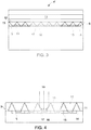
- An exemplary non-limiting shape of the light redirection layer 9 is illustrated in Figure 4 . As shown, the top and the bottom of the light redirection layer are substantially flat, which enables the light redirection to rest substantially directly on the pixel layer, in an adjacent flush manner to minimize or eliminate space or gaps therebetween if desired.
- the channels 12 of the light redirecting cells 18 are shaped to reflect light into the corresponding pixel(s) 5 (of the pixel layer 14) associated with each cell. As illustrated e.g.in Fig. 3 , the channel defines an opening proximate to the scintillator layer 13. Additionally, the channel dimensionally tapers downward from the opening in a direction from the scintillator toward the pixel layer 14; in other words, the area of channel opening proximate to the scintillator layer is greater that the area of the channel opening proximate the pixel layer.
- the bottom opening of the channel is sized and/or configured to approximate the size and configuration of the light sensitive part of the pixel 17 and, in at least one exemplary non-limiting embodiment, is sized and/or configured to be substantially or exactly the size and/or configuration of the light sensitive area of the pixel 17.
- the channel 12 is made of any material allowing light to pass through said material to the pixels 5 of the pixel layer 14, including, but not limited to a solid, fluid, or combinations thereof..
- the light reflective regions 11 is adjacent to the channel 12.
- the respective light reflective regions 11 are configured to cover (wholly or partially) the respective nonlight sensitive areas 16 of the pixels forming the pixel layer 14.
- Each light reflective region 11 is configured so that it tapers in a narrowing fashion in a direction from the pixel later toward the scintillator layer.
- the light reflective region 11 can be made of any material that reflects light including, but not limited to, a solid, fluid, or combinations thereof.
- the channel 12 and the light reflective region 11 abut to form an interface 10.
- the interface 10 is created and defined by the meeting of the substances.
- the interface 10 creates an angle in relation to the light sensitive part of the pixel on the channel side of the light redirection cell. This angle is typically an obtuse angle, but other angles are contemplated.
- the interface 10 is the point or region at which the light 18 will be reflected and redirected into the pixel 14.
- the reflective region comprises several layered substances 11a, 11b, 11c, (See Figure 6 ) thus multiple interfaces may exist.
- the light reflective region 11 may not be light reflective in its entirety.
- the portion of the light reflective region 11 that creates the interface 10 with the channel 12 may, in at least one non-limiting embodiment, be the only reflective portion of the light reflective region 11, while the other portions(s) are not light reflective.
- the light reflective region 11 can be light reflective in its entirety, or reflective in certain portions other than or including the interface region noted above.
- Figure 4 is a cross section of the light redirection layer 9 in conjunction with the pixel layer 14.
- the pixel layer 14 comprises at least one pixel 5.
- Each pixel 5 comprises two areas; a light sensitive area or region 17 and a non-light sensitive area or region 16.
- the light sensitive area of each pixel 17 is the region where light is measured in order to be processed into an x-ray image.
- the pixel layer 14 comprises multiple pixels. These pixels are placed end to end so that the non-light sensitive regions are adjacent to each other creating seams 15 of the pixels in the pixel layer 14. The seams 15 will leave missing data. As illustrated, the seams 15 are covered by the light reflective regions 11. This configuration allows the light 19 to be reflected off of the light reflective region 11 and be redirected into the light sensitive area 17 of the pixel 5. This configuration prevents light from being lost between pixels, in the seams 15 or in the non-light sensitive areas 16 of the pixels.
- the pixels 5 are square-shaped or substantially square-shaped. It should be noted, however that the pixels 5 that form the pixel layer 14 do not need to be square or even substantially square for the light redirection layer 9 to redirect light into the light sensitive area of the pixel 17; accordingly, other known shapes can be implemented. Also, the light sensitive area 17 of the pixel does not need to be square or substantially square; it can be any shape. And the non-light sensitive area 16 does need to be square in perimeter; it can be any shape the designer desires.
- the non-light sensitive area 16 of the pixel 5 is approximately half of the light sensitive area 17 of the pixel.
- the non-light sensitive area 16 of the pixel is not limited to this ratio.
- FIG 4 shows in detail the light redirection layer 9.
- the light redirection layer 9 is made up of one or more light redirection cells 18 (See e.g. Fig. 5 ).
- the light redirecting cells 18 comprise the aforementioned channels 12 and light reflective regions 11.
- the light redirecting cells 18 are generally defined by the shape of the pixel 5, including both the light sensitive area 17 and the non-light sensitive area 16 of the pixel 5.
- the general shape of the light redirection layer 9 is illustrated in Figure 4 .
- the top and the bottom of the light redirection layers are substantially flat. The flat top and bottom allows the layer to rest on the pixel layer 14.
- Each channel 12 of a respective light redirecting cell 18 is shaped to reflect light into the pixel 5.
- the channel has a wide opening closest to the scintillator.
- the channel tapers from the scintillator side to a smaller opening at the pixel side of the light redirection layer.
- the bottom opening of the channel is approximately (e.g. larger or smaller) the size the light sensitive part of the pixel 17 and in an at least embodiment, the bottom opening of the channel is the same size as the light sensitive area of the pixel 17.
- the channel 12 is made of a material that will allow light to pass through. Generally, this is a material that can be a fluid, solid, or any other light substance conducive to light passing through to the at least one pixel 5.
- the light reflective region 11 is adjacent to the channel 12.
- the light reflective region 11 covers the nonlight sensitive area 16 of the pixel 5 and tapers in a direction from the pixel layer 14 toward the scintillator 13.
- the light reflective region 11 can be made of any material that reflects light including but not limited to any solid, fluid, or other substance.
- the channel 12 and the light reflecting region 11 abut to form an interface 10.
- the interface 10 is created by the meeting of the substances.
- the interface 10 creates an angle in relation to the light sensitive part of the pixel on the channel side of the light redirection cell. This angle is an obtuse angle.
- the interface 10 is the region where the light 19 will be reflected and thus redirected into light sensitive area of the pixel 17.
- the reflective region comprises several layered substances 11a, 11b, 11c, (See Figure 6 ) thus multiple interfaces may exist.
- the light reflective region 11 may not be light reflective as a whole.
- the part of the light reflective region 11 that creates the interface 10 with the channel 12 may be the only part of the light reflective region 11 that is reflective. In this embodiment the other area of the light reflective region 11 need not be reflective.
- Figure 5 depicts a light redirecting cell 18.
- the light redirecting cell comprises a light reflective region 11 and a channel 12 with an interface 10 therebetween.
- the light reflective region 11 is configured to cover, in whole or in part, the non-light sensitive area 16 of the pixel 5, then tapers outwardly to the top of the light redirection layer 14 (i.e. tapers outwardly in a direction toward the scintillator ( Fig. 3 ).
- the meeting of the light reflective region 11 and the channel 12 creates the interface 10 that is the first area of flection. This interface 10 is angled so light will travel toward the light sensitive area 17 of the pixel 5.
- an aerial view of the light redirection layer 9 is shown in Figure 6 .
- the light redirection cells 18 can be viewed and the parameters of the light redirection cell can be seen, including the outer perimeters 20 of the light redirecting cells and the interface 10 between the channel 12 and the light reflective region 11.
- the shape of the cell is determined by the shape of the pixel (not shown) which it is reflecting light into.
- the pixel is square-shaped or substantially square-shaped, thus the light redirection cell 18 is the general shape of an inverted pyramid.
- the pixel could take on a different shape, for example circular or triangular, thus the interface 10 and the perimeter or perimetric border 20 between the light redirection cells will be different in shape to coincide with the pixel shape.
- the light reflective region 11 can be made of multiple layers 11a, 11b, 11c.
- the first layer 11a being less reflective than the subsequent layers 11b, 11c.
- the subsequent layers 11b, 11c will reflect light that permeates the first layer 11a and enter into the light sensitive area 17 of the at least one pixel.
- Figure 7 shows an embodiment of an arrangement of an x-ray source 1 relative to the elements of the x-ray detector 4 .
- the scintillator 13 is located closer than the pixels 5 and pixel layer 14 than the x-ray source 1.
- x-rays are emitted from the x-ray source 1 into the detector 4 .
- the x-rays are received in the scintillator 13 after passing through the light redirection layer 9 and the pixel layer 14.
- the scintillator 13 then converts the x-rays into light.
- the light then passes through the light redirection layer 9 into the pixel layer 14, more specifically into the light sensitive areas 17 of the pixels 5.
- an arrangement of an x-ray source 1 relative to the elements in a detector 4' comprises a scintillator 13, the light redirection layer 9, and pixel layer 14.
- the scintillator 13 is located closer to the x-ray source than the pixel layer 14.
- the x-rays are emitted from the x-ray source 1, into the detector 4'.
- the x-rays are received in the scintillator 13 before passing through the light redirection layer 9 and the pixels 14.
- the scintillator 13 then converts the x-rays into light.
- the light then passes through the light redirection layer 9 into the pixels.
- X-rays are emitted from the x-ray source 1 and pass through the subject of interest 2.
- the x-rays then enter the detector 4'.
- the x-rays are converted into light by a scintillator 13 and then pass through a light redirection layer 9, See figures 3-7 .
- the redirection layer 9 As light enters the redirection layer 9 it enters a light redirection cell 18. Light is reflected off of the light reflective region 11 at the interface 10 (See figure 4 ) and is reflected at an angle toward the light sensitive area 17 of the pixels 5. The redirected light enters the light sensitive areas 17 of the pixels 5 and generates an electrical signal proportional to the amount of x-rays incident on a scintillator 13 area above it. Data from the pixels 5 is processed to form one or more x-ray images that are displayed on a display or screen 8. Additionally, the data may be stored in a memory unit 7.
- the present invention is not limited to the configuration shown, but rather, the configuration shown gives context to the present invention.
- the configuration of the light redirecting cell creates advantages. For example, the light that would normally be lost between pixels is redirected an absorbed by a pixel. At least one other advantage is that the at least one pixel can have more electronics surrounding the light sensitive area of the at least on pixel. This will increase pixel sensitivity without losing light between pixels.
- the pixel can be any shape.
- the pixel shape can be changed more easily because of the light redirection layer.
- the light redirection layer can be changed to accommodate different shapes.
- the light reflective region will taper toward the edge of the light sensitive area of the pixel covering the non-light sensitive area of the pixel no matter the shape of the non-light sensitive area and the light sensitive area.
- At least one advantage to the light redirection layer is the ability to increase or decrease the non-light sensitive area of the pixel without losing light data in the non-light sensitive area. But, the light redirection layer will change according to the shape of the pixel.
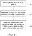
- Figure 8 shows a method of redirecting light from an x-ray detector scintillator toward the light sensitive area of a pixel.
- x-rays are emitted from the x-ray source.
- the x-rays that are emitted pass through the object that is to be imaged.
- the x-rays are either absorbed in to the object or the x-rays pass through the object.
- the x-rays that have passed through the object, enter the x-ray detector and are received in the scintillator.
- the scintillator then converts the x-rays into light.
- the layer consists of light redirecting cells.
- the light redirecting cell redirects the light away from the nonlight sensitive part of the pixel and toward the light sensitive part of the pixel.
- the light redirection cell comprises a channel and a light reflective region. The channel directs the light toward the light sensitive part of the pixel and the light reflective region of the light redirection cell prevents the light from entering the non-light sensitive part of the pixel.
- pixel is used throughout the specification and should be interpreted to include one or more pixel.
- the term pixel is not restricted by any number because of the use of singular or multiple form.
- the functional blocks are not necessarily indicative of the division between hardware circuitry.
- one or more of the functional blocks may be implemented in a single piece of hardware (for example, a general purpose signal processor, microcontroller, random access memory, hard disk, and the like).
- the programs may be stand-alone programs, maybe incorporated as subroutines in an operating system, maybe functions in an installed software package, and the like.
- the various embodiments are not limited to the arrangements and instrumentality shown in the drawings.
Landscapes
- Health & Medical Sciences (AREA)
- Life Sciences & Earth Sciences (AREA)
- Physics & Mathematics (AREA)
- High Energy & Nuclear Physics (AREA)
- Molecular Biology (AREA)
- Spectroscopy & Molecular Physics (AREA)
- General Physics & Mathematics (AREA)
- Engineering & Computer Science (AREA)
- Medical Informatics (AREA)
- Biomedical Technology (AREA)
- Animal Behavior & Ethology (AREA)
- Radiology & Medical Imaging (AREA)
- Optics & Photonics (AREA)
- Heart & Thoracic Surgery (AREA)
- Nuclear Medicine, Radiotherapy & Molecular Imaging (AREA)
- Surgery (AREA)
- Pathology (AREA)
- General Health & Medical Sciences (AREA)
- Public Health (AREA)
- Veterinary Medicine (AREA)
- Biophysics (AREA)
- Mathematical Physics (AREA)
- Apparatus For Radiation Diagnosis (AREA)
- Measurement Of Radiation (AREA)
Abstract
Description
- A number of radiological imaging systems of various designs are known. Radiological imaging systems generally are based upon generation of X-rays that are directed toward a subject of interest. The X-rays traverse the subject and impact a film or a digital detector. In medical diagnostic contexts, for example, such systems may be used to visualize internal tissues and diagnose patient ailments. In other contexts, parts, baggage, parcels, and other subjects may be imaged to assess their contents and for other purposes.
- Many of the earlier radiographic imaging systems employ conventional X-ray imaging using film as the X-ray detection media. In order to obtain images from these systems, the imaging medium must be transported and processed after each exposure, resulting in a time delay in obtaining the desired images. Digital radiography provides an alternative that allows the acquisition of image data and reconstructed images on the spot for quicker viewing and diagnosis, and allows for images to be readily stored and transmitted to the viewing professional. These digital images displayed in digital form may not represent all of the x-rays that have passed through the subject of interest because some light, which was converted from the x-rays, is lost between the pixels. This creates a less precise image of the subject of interest and possible error.
- In an embodiment, an x-ray detector comprises a scintillator configured to convert x-rays into light and a light redirection layer configured to redirect light from the scintillator to at least one pixel. The light redirection layer comprises at least one light redirecting cell comprising a channel and a light reflector region, the channel being arranged relative to the at least one pixel to direct incoming light away from a non-light sensitive part of the at least one pixel and toward the light sensitive part of the at least one pixel.
- In another embodiment, a method for redirecting light comprises emitting x-rays from an x-ray source. The x-rays received by the scintillator are converted into light. The light is received into the light redirection layer and the light is redirected in the light redirecting layer using at least one light redirecting cell comprising a channel and a light reflective region, the channel being arranged relative to the at least on pixel to channel incoming light away from a non-light sensitive part of the at least one pixel and toward the light sensitive part of the at least one pixel.
- In a further embodiment, an x-ray system comprises an x-ray source configured to generate x-rays and an x-ray receptor or detector. The receptor or detector comprises a scintillator configured to convert x-rays into light and a light redirection layer. The light redirection layer is configured to redirect light from the scintillator to at least one pixel. The light redirection layer comprises at least one light redirecting cell comprising a channel and a light reflecting region, the channel arranged relative to the at least one pixel to direct incoming light away from a non-light sensitive part of the at least one pixel and toward the light sensitive part of the at least one pixel.
- The inventive subject matter described herein will be better understood from reading the following description of non-limiting embodiments, with reference to the attached drawings, wherein below:
-
FIG. 1 is a schematic diagram of an x-ray imaging system; -
FIG. 2 is a cross-sectional schematic of an embodiment of an x-ray detector usable, for example, in the x-ray imaging system ofFIG. 1 ; -
FIG. 3 is a cross-sectional schematic of an embodiment of the x-ray detector ofFIG. 2 comprising a light redirection layer; -
FIG. 4 is a cross-sectional schematic of an embodiment of the light redirection layer and pixel layers of the x-ray detector shown inFIG.. 3 ; -
FIG. 5 is a cross-sectional schematic of an embodiment of a light redirection cell and corresponding pixel of the x-ray detector and elements shown inFIGS. 3-4 ; -
FIG. 6 is a top/side elevational view of the embodiment of the light redirection cell and pixel shown inFIG. 5 ; -
FIG. 7 is a schematic illustration of alternative arrangements of an x-ray source relative to the x-ray detector and elements shown inFIGS. 2-6 ; and -
FIG. 8 is a schematic illustration of a method for redirecting light. - Reference will be made below in detail to exemplary embodiments of the inventive subject matter, examples of which are illustrated in the accompanying drawings. Wherever possible, the same reference numerals used throughout the drawings refer to the same or like parts.
- Although exemplary embodiments of the inventive subject matter are described with respect to medical x-ray detectors the current application applies to all types of x-ray detectors.
- Referring to
figure 1 , X-ray imaging systems generally comprise any or all of anx-ray source 1 and anx-ray detector 4 configured to image an object or subject ofinterest 2, anobject support 3, adisplay screen 8, and a processor 6 which may include amemory 7. An exemplary non-limiting embodiment of an imaging system is described inUS 8,563,938 , which is commonly owned by General Electric Company and is incorporated by reference herein. - X-ray detectors are devices configured to generate images by converting x-rays into light, detecting the amount of converted light and transmitting a corresponding electric signal to a computer or processor that will construct an image from the signal for viewing on an integrated or separate display. An exemplary non-limiting example of an X-ray detectors is depicted in
Figure 2 . Thex-ray detector 4 comprises ascintillator 13 and apixel layer 14. Thepixel layer 14 comprisesmultiple pixels 5, eachpixel 5 having a nonlightsensitive area 16 and lightsensitive area 17. The nonlightsensitive area 16 comprises one or more electronic components. - Now drawing attention to
Figure 3 , a cross-section of an exemplary non-limiting embodiment of an x-ray detector is shown. The detector 4' comprises ascintillator 13, alight redirection layer 9, andpixel layer 14. In the depicted arrangement, thescintillator 13 is positioned closer to or biased toward thelight redirection layer 9 in comparison to thepixel layer 14. This configuration enables the x-rays that have been turned into light in thescintillator 13 to pass through theredirection layer 9 before entering thepixels 14. - Attention will now be drawn to the light redirection layer 9 (See
Figs 3-6 ). Thelight redirection layer 9 is made up of one or morelight redirection cells 18, shown in greater detail inFig. 5 . Eachlight redirecting cell 18 comprises, in part, alight reflection region 11 and achannel 12. Thelight redirecting cells 18 are generally defined by the shape of thepixels 5, including both the non-lightsensitive area 16 and the lightsensitive area 17. An exemplary non-limiting shape of thelight redirection layer 9 is illustrated inFigure 4 . As shown, the top and the bottom of the light redirection layer are substantially flat, which enables the light redirection to rest substantially directly on the pixel layer, in an adjacent flush manner to minimize or eliminate space or gaps therebetween if desired. - The
channels 12 of thelight redirecting cells 18 are shaped to reflect light into the corresponding pixel(s) 5 (of the pixel layer 14) associated with each cell. As illustrated e.g.inFig. 3 , the channel defines an opening proximate to thescintillator layer 13. Additionally, the channel dimensionally tapers downward from the opening in a direction from the scintillator toward thepixel layer 14; in other words, the area of channel opening proximate to the scintillator layer is greater that the area of the channel opening proximate the pixel layer. To maximize the amount of light received by thepixel layer 14, the bottom opening of the channel is sized and/or configured to approximate the size and configuration of the light sensitive part of thepixel 17 and, in at least one exemplary non-limiting embodiment, is sized and/or configured to be substantially or exactly the size and/or configuration of the light sensitive area of thepixel 17. Thechannel 12 is made of any material allowing light to pass through said material to thepixels 5 of thepixel layer 14, including, but not limited to a solid, fluid, or combinations thereof.. - The light
reflective regions 11 is adjacent to thechannel 12. The respective lightreflective regions 11 are configured to cover (wholly or partially) the respective nonlightsensitive areas 16 of the pixels forming thepixel layer 14. Each lightreflective region 11 is configured so that it tapers in a narrowing fashion in a direction from the pixel later toward the scintillator layer. The lightreflective region 11 can be made of any material that reflects light including, but not limited to, a solid, fluid, or combinations thereof. - The
channel 12 and the lightreflective region 11 abut to form aninterface 10. Theinterface 10 is created and defined by the meeting of the substances. Theinterface 10 creates an angle in relation to the light sensitive part of the pixel on the channel side of the light redirection cell. This angle is typically an obtuse angle, but other angles are contemplated. Theinterface 10 is the point or region at which thelight 18 will be reflected and redirected into thepixel 14. In some embodiments, the reflective region comprises severallayered substances Figure 6 ) thus multiple interfaces may exist. - The light
reflective region 11 may not be light reflective in its entirety. For example, the portion of the lightreflective region 11 that creates theinterface 10 with thechannel 12 may, in at least one non-limiting embodiment, be the only reflective portion of the lightreflective region 11, while the other portions(s) are not light reflective. Of course, the lightreflective region 11 can be light reflective in its entirety, or reflective in certain portions other than or including the interface region noted above. -
Figure 4 is a cross section of thelight redirection layer 9 in conjunction with thepixel layer 14. Thepixel layer 14 comprises at least onepixel 5. Eachpixel 5 comprises two areas; a light sensitive area orregion 17 and a non-light sensitive area orregion 16. The light sensitive area of eachpixel 17 is the region where light is measured in order to be processed into an x-ray image. - In an exemplary non-limiting embodiment, the
pixel layer 14 comprises multiple pixels. These pixels are placed end to end so that the non-light sensitive regions are adjacent to each other creatingseams 15 of the pixels in thepixel layer 14. Theseams 15 will leave missing data. As illustrated, theseams 15 are covered by the lightreflective regions 11. This configuration allows the light 19 to be reflected off of the lightreflective region 11 and be redirected into the lightsensitive area 17 of thepixel 5. This configuration prevents light from being lost between pixels, in theseams 15 or in the non-lightsensitive areas 16 of the pixels. - In
figure 4 thepixels 5 are square-shaped or substantially square-shaped. It should be noted, however that thepixels 5 that form thepixel layer 14 do not need to be square or even substantially square for thelight redirection layer 9 to redirect light into the light sensitive area of thepixel 17; accordingly, other known shapes can be implemented. Also, the lightsensitive area 17 of the pixel does not need to be square or substantially square; it can be any shape. And the non-lightsensitive area 16 does need to be square in perimeter; it can be any shape the designer desires. - Additionally, in the
figure 4 depiction the non-lightsensitive area 16 of thepixel 5 is approximately half of the lightsensitive area 17 of the pixel. The non-lightsensitive area 16 of the pixel is not limited to this ratio. -
Figure 4 shows in detail thelight redirection layer 9. Thelight redirection layer 9 is made up of one or more light redirection cells 18 (See e.g.Fig. 5 ). The light redirectingcells 18 comprise theaforementioned channels 12 and lightreflective regions 11. The light redirectingcells 18 are generally defined by the shape of thepixel 5, including both the lightsensitive area 17 and the non-lightsensitive area 16 of thepixel 5. The general shape of thelight redirection layer 9 is illustrated inFigure 4 . The top and the bottom of the light redirection layers are substantially flat. The flat top and bottom allows the layer to rest on thepixel layer 14. - Each
channel 12 of a respectivelight redirecting cell 18 is shaped to reflect light into thepixel 5. The channel has a wide opening closest to the scintillator. The channel tapers from the scintillator side to a smaller opening at the pixel side of the light redirection layer. The bottom opening of the channel is approximately (e.g. larger or smaller) the size the light sensitive part of thepixel 17 and in an at least embodiment, the bottom opening of the channel is the same size as the light sensitive area of thepixel 17. Thechannel 12 is made of a material that will allow light to pass through. Generally, this is a material that can be a fluid, solid, or any other light substance conducive to light passing through to the at least onepixel 5. - The light
reflective region 11 is adjacent to thechannel 12. The lightreflective region 11 covers the nonlightsensitive area 16 of thepixel 5 and tapers in a direction from thepixel layer 14 toward thescintillator 13. The lightreflective region 11 can be made of any material that reflects light including but not limited to any solid, fluid, or other substance. - The
channel 12 and thelight reflecting region 11 abut to form aninterface 10. Theinterface 10 is created by the meeting of the substances. Theinterface 10 creates an angle in relation to the light sensitive part of the pixel on the channel side of the light redirection cell. This angle is an obtuse angle. Theinterface 10 is the region where the light 19 will be reflected and thus redirected into light sensitive area of thepixel 17. In some embodiments, the reflective region comprises several layeredsubstances Figure 6 ) thus multiple interfaces may exist. - In some embodiments, the light
reflective region 11 may not be light reflective as a whole. The part of the lightreflective region 11 that creates theinterface 10 with thechannel 12 may be the only part of the lightreflective region 11 that is reflective. In this embodiment the other area of the lightreflective region 11 need not be reflective. -
Figure 5 depicts alight redirecting cell 18. As illustrated, the light redirecting cell comprises a lightreflective region 11 and achannel 12 with aninterface 10 therebetween. The lightreflective region 11 is configured to cover, in whole or in part, the non-lightsensitive area 16 of thepixel 5, then tapers outwardly to the top of the light redirection layer 14 (i.e. tapers outwardly in a direction toward the scintillator (Fig. 3 ). The meeting of the lightreflective region 11 and thechannel 12 creates theinterface 10 that is the first area of flection. Thisinterface 10 is angled so light will travel toward the lightsensitive area 17 of thepixel 5. - In a non-limiting embodiment, an aerial view of the
light redirection layer 9 is shown inFigure 6 . In this embodiment, thelight redirection cells 18 can be viewed and the parameters of the light redirection cell can be seen, including theouter perimeters 20 of the light redirecting cells and theinterface 10 between thechannel 12 and the lightreflective region 11. The shape of the cell is determined by the shape of the pixel (not shown) which it is reflecting light into. In this case, the pixel is square-shaped or substantially square-shaped, thus thelight redirection cell 18 is the general shape of an inverted pyramid. In other embodiments, the pixel could take on a different shape, for example circular or triangular, thus theinterface 10 and the perimeter orperimetric border 20 between the light redirection cells will be different in shape to coincide with the pixel shape. - In at least one non-limiting embodiment, depicted in
figure 6 , the lightreflective region 11 can be made ofmultiple layers first layer 11a being less reflective than thesubsequent layers subsequent layers first layer 11a and enter into the lightsensitive area 17 of the at least one pixel. -
Figure 7 shows an embodiment of an arrangement of anx-ray source 1 relative to the elements of thex-ray detector 4 . Specifically, the arrangement of thex-ray source 1 to thescintillator 13 and thelight redirection layer 9. In an embodiment, thescintillator 13 is located closer than thepixels 5 andpixel layer 14 than thex-ray source 1. In this embodiment, x-rays are emitted from thex-ray source 1 into thedetector 4 . The x-rays are received in thescintillator 13 after passing through thelight redirection layer 9 and thepixel layer 14. Thescintillator 13 then converts the x-rays into light. The light then passes through thelight redirection layer 9 into thepixel layer 14, more specifically into the lightsensitive areas 17 of thepixels 5. - In another embodiment, shown in
figure 7 , an arrangement of anx-ray source 1 relative to the elements in a detector 4'. Here the detector 4' comprises ascintillator 13, thelight redirection layer 9, andpixel layer 14. In this embodiment, thescintillator 13 is located closer to the x-ray source than thepixel layer 14. The x-rays are emitted from thex-ray source 1, into the detector 4'. The x-rays are received in thescintillator 13 before passing through thelight redirection layer 9 and thepixels 14. Thescintillator 13 then converts the x-rays into light. The light then passes through thelight redirection layer 9 into the pixels. - Having thus described embodiments of the invention, attention will now be drawn to a non-limiting example of how the x-ray detector 4' operates within a typical x-ray imaging system. X-rays are emitted from the
x-ray source 1 and pass through the subject ofinterest 2. The x-rays then enter the detector 4'. In the detector 4', the x-rays are converted into light by ascintillator 13 and then pass through alight redirection layer 9, Seefigures 3-7 . - As light enters the
redirection layer 9 it enters alight redirection cell 18. Light is reflected off of the lightreflective region 11 at the interface 10 (Seefigure 4 ) and is reflected at an angle toward the lightsensitive area 17 of thepixels 5. The redirected light enters the lightsensitive areas 17 of thepixels 5 and generates an electrical signal proportional to the amount of x-rays incident on ascintillator 13 area above it. Data from thepixels 5 is processed to form one or more x-ray images that are displayed on a display orscreen 8. Additionally, the data may be stored in amemory unit 7. The present invention is not limited to the configuration shown, but rather, the configuration shown gives context to the present invention. - The configuration of the light redirecting cell creates advantages. For example, the light that would normally be lost between pixels is redirected an absorbed by a pixel. At least one other advantage is that the at least one pixel can have more electronics surrounding the light sensitive area of the at least on pixel. This will increase pixel sensitivity without losing light between pixels.
- At least one advantage to the light redirection layer is that the pixel can be any shape. The pixel shape can be changed more easily because of the light redirection layer. The light redirection layer can be changed to accommodate different shapes. The light reflective region will taper toward the edge of the light sensitive area of the pixel covering the non-light sensitive area of the pixel no matter the shape of the non-light sensitive area and the light sensitive area.
- At least one advantage to the light redirection layer is the ability to increase or decrease the non-light sensitive area of the pixel without losing light data in the non-light sensitive area. But, the light redirection layer will change according to the shape of the pixel.
-
Figure 8 shows a method of redirecting light from an x-ray detector scintillator toward the light sensitive area of a pixel. - At
step 21, x-rays are emitted from the x-ray source. The x-rays that are emitted pass through the object that is to be imaged. The x-rays are either absorbed in to the object or the x-rays pass through the object. - At
step 22, the x-rays, that have passed through the object, enter the x-ray detector and are received in the scintillator. The scintillator then converts the x-rays into light. - At
step 23, the light enters into the light redirecting layer. The layer consists of light redirecting cells. The light redirecting cell redirects the light away from the nonlight sensitive part of the pixel and toward the light sensitive part of the pixel. The light redirection cell comprises a channel and a light reflective region. The channel directs the light toward the light sensitive part of the pixel and the light reflective region of the light redirection cell prevents the light from entering the non-light sensitive part of the pixel. - It is to be understood that the description is intended to be illustrative, and not restrictive. For example, the above-described embodiments (and/or aspects thereof) may be used in combination with each other. In addition, many modifications may be made to adapt a particular situation or material to the teachings of the inventive subject matter without departing from its scope. While the dimensions and types of materials described herein are intended to define the parameters of the inventive subject matter, they are by no means limiting and are exemplary embodiments. Many other embodiments will be apparent to those of ordinary skill in the art upon reviewing the above description. The scope of the inventive subject matter should, therefore, be determined with reference to the appended claims, along with the full scope of equivalents to which such claims are entitled. In the appended claims, the terms "including" and "in which" are used as the plain-English equivalents of the respective terms "comprising" and "wherein." Moreover, in the following claims, the terms "first," "second," and "third," etc. are used merely as labels, and are not intended to impose numerical requirements on their objects.
- Additionally, the term pixel is used throughout the specification and should be interpreted to include one or more pixel. The term pixel is not restricted by any number because of the use of singular or multiple form.
- This written description uses examples to disclose several embodiments of the inventive subject matter and also to enable any person of ordinary skill in the art to practice the embodiments of the inventive subject matter, including making and using any devices or systems and performing any incorporated methods. The patentable scope of the inventive subject matter is defined by the claims, and may include other examples that occur to those of ordinary skill in the art. Such other examples are intended to be within the scope of the claims if they have structural elements that do not differ from the literal language of the claims, or if they include equivalent structural elements with insubstantial differences from the literal languages of the claims.
- The foregoing description of certain embodiments of the inventive subject matter will be better understood when read in conjunction with the appended drawings. To the extent that the figures illustrate diagrams of the functional blocks of various embodiments, the functional blocks are not necessarily indicative of the division between hardware circuitry. Thus, for example, one or more of the functional blocks (for example, processors or memories) may be implemented in a single piece of hardware (for example, a general purpose signal processor, microcontroller, random access memory, hard disk, and the like). Similarly, the programs may be stand-alone programs, maybe incorporated as subroutines in an operating system, maybe functions in an installed software package, and the like. The various embodiments are not limited to the arrangements and instrumentality shown in the drawings.
- As used herein, an element or step recited in the singular and proceeded with the word "a" or "an" should be understood as not excluding plural of said elements or steps, unless such exclusion is explicitly stated. Furthermore, references to "one embodiment" of the inventive subject matter are not intended to be interpreted as excluding the existence of additional embodiments that also incorporate the recited features. Moreover, unless explicitly stated to the contrary, embodiments "comprising," "including," or "having" an element or a plurality of elements having a particular property may include additional such elements not having that property.
- Since certain changes may be made in the above-described systems and methods, without departing from the spirit and scope of the inventive subject matter herein involved, it is intended that all of the subject matter of the above description or shown in the accompanying drawings shall be interpreted merely as examples illustrating the inventive concept herein and shall not be construed as limiting the inventive subject matter.
- Various aspects and embodiments of the present invention are defined by the following numbered clauses:
- 1. An x-ray detector comprising:
- a scintillator configured to convert x-rays into light; and
- a light redirection layer configured to redirect light from the scintillator to at least one pixel, the light redirection layer comprising at least one light redirecting cell comprising a channel and a light reflecting region, the channel arranged relative to the at least one pixel to direct incoming light away from a non-light sensitive part of the at least one pixel and toward the light sensitive part of the at least one pixel.
- 2. The device of
clause 1, wherein the light reflecting region is adjacent to the channel to define a light reflecting interface tapering toward the at least one pixel. - 3. The device of any preceding clause, wherein the channel comprises a first substance and the light reflecting region comprises a second substance.
- 4. The device of any preceding clause, wherein the first substance is a light permissive polymer and the second substance is a light reflecting polymer.
- 5. The device of any preceding clause, wherein the light reflecting region comprises multiple layers with different refractive indexes.
- 6. The device of any preceding clause, wherein the first substance is a light permissive polymer and the second substance is a fluid.
- 7. The device of any preceding clause, wherein the first substance is a fluid and the second substance is a light reflecting polymer.
- 8. A method of redirecting light comprising:
- emitting x-rays from an x-ray source;
- receiving x-rays into a scintillator;
- converting the x-rays into light;
- receiving light into the light redirection layer; and
- redirecting light in the light redirecting layer away from a non-light sensitive part of the at least one pixel and toward the light sensitive part of the at least one pixel.
- 9. The method of any preceding clause, wherein the light reflecting region is adjacent to the channel to define a light reflecting interface tapering toward the at least one pixel.
- 10. The method of any preceding clause, wherein the scintillator receives x-rays from the side of the scintillator that is facing an x-ray source, converts the x-rays to light, and emits light from the side of the scintillator that is not facing the x-ray source into the light redirection layer.
- 11. The method of any preceding clause, wherein the scintillator receives x-rays through the light redirection layer into the side of the scintillator that is facing an x-ray source, converts the x-rays to light, and emits light from the side of the scintillator that is facing the x-ray source into the light redirection layer.
- 12. A x-ray system comprising:
- an x-ray source configured to generate x-rays; and
- an x-ray receptor or detector comprising:
- a scintillator configured to convert x-rays into light; and
- a light redirection layer configured to redirect light from the scintillator to at least one pixel, the light redirection layer comprising at least one light redirecting cell comprising a channel and a light reflecting region, the channel arranged relative to the at least one pixel to direct incoming light away from a non-light sensitive part of the at least one pixel and toward the light sensitive part of the at least one pixel.
- 13. The device of any preceding clause, wherein the light reflecting region is adjacent to the channel to define a light reflecting interface tapering toward the at least one pixel.
- 14. The device of any preceding clause, wherein the channel comprises a first substance and the light reflecting region comprises a second substance.
- 15. The device of any preceding clause, wherein the first substance is a light permissive polymer and the second substance is a light reflecting polymer.
- 16. The device of any preceding clause, wherein the light reflecting region comprises multiple layers with different refractive indexes.
- 17. The device of any preceding clause, wherein the first substance is a light permissive polymer and the second substance is a fluid.
- 18. The device of any preceding clause, wherein the first substance is a fluid and the second substance is a light reflecting polymer.
Claims (15)
- An x-ray detector (4) comprising:a scintillator (13) configured to convert x-rays into light; anda light redirection layer (9) configured to redirect light from the scintillator (13) to at least one pixel (5), the light redirection layer (9) comprising at least one light redirecting cell (18) comprising a channel (12) and a light reflecting region (11), the channel (12) arranged relative to the at least one pixel (5) to direct incoming light away from a non-light sensitive part (16) of the at least one pixel (5) and toward the light sensitive part (17) of the at least one pixel (5).
- The device (4) of claim 1, wherein the light reflecting region (11) is adjacent to the channel (12) to define a light reflecting interface tapering toward the at least one pixel (5).
- The device (4) of any preceding claim, wherein the channel (12) comprises a first substance and the light reflecting region comprises a second substance.
- The device (4) of claim 3, wherein the first substance is a light permissive polymer and the second substance is a light reflecting polymer.
- The device (4) of any preceding claim, wherein the light reflecting region (11) comprises multiple layers (11a,11b) with different refractive indexes.
- The device (4) of any preceding claim, wherein the first substance is a light permissive polymer and the second substance is a fluid.
- The device (4) of any preceding claim, wherein the first substance is a fluid and the second substance is a light reflecting polymer.
- A method of redirecting light comprising:emitting (21) x-rays from an x-ray source;receiving (22) x-rays into a scintillator;converting the x-rays into light;receiving (23) light into the light redirection layer (9); andredirecting light in the light redirecting layer (9) away from a non-light sensitive part (16) of the at least one pixel (5) and toward the light sensitive part (17) of the at least one pixel (5).
- The method of claim 8, wherein the light reflecting region (11) is adjacent to the channel (12) to define a light reflecting interface tapering toward the at least one pixel (5).
- The method of claim 8 or claim 9, wherein the scintillator (13) receives x-rays from the side of the scintillator that is facing an x-ray source, converts the x-rays to light, and emits light from the side of the scintillator that is not facing the x-ray source into the light redirection layer.
- The method of any of claims 8 to 10, wherein the scintillator (13) receives x-rays through the light redirection layer (9) into the side of the scintillator (13) that is facing an x-ray source, converts the x-rays to light, and emits light from the side of the scintillator that is facing the x-ray source into the light redirection layer.
- A x-ray system comprising:an x-ray source (1) configured to generate x-rays; andan x-ray receptor or detector (4) comprising:a scintillator (13) configured to convert x-rays into light; anda light redirection layer (9) configured to redirect light from the scintillator (13) to at least one pixel (5), the light redirection layer (9) comprising at least one light redirecting cell (18) comprising a channel (12) and a light reflecting region (11), the channel (12) arranged relative to the at least one pixel (5) to direct incoming light away from a non-light sensitive part (16) of the at least one pixel (5) and toward the light sensitive part (17) of the at least one pixel (5).
- The system of claim 12, wherein the light reflecting region (11) is adjacent to the channel (12) to define a light reflecting interface tapering toward the at least one pixel (5).
- The system of claim 12 or claim 13, wherein the channel (12) comprises a first substance and the light reflecting region comprises a second substance.
- The system of claim 14, wherein the first substance is a light permissive polymer and the second substance is a light reflecting polymer.
Applications Claiming Priority (1)
| Application Number | Priority Date | Filing Date | Title |
|---|---|---|---|
| US15/396,660 US10677935B2 (en) | 2016-12-31 | 2016-12-31 | Light guide layer for a radiographic device |
Publications (1)
| Publication Number | Publication Date |
|---|---|
| EP3346292A1 true EP3346292A1 (en) | 2018-07-11 |
Family
ID=60937524
Family Applications (1)
| Application Number | Title | Priority Date | Filing Date |
|---|---|---|---|
| EP17208007.9A Withdrawn EP3346292A1 (en) | 2016-12-31 | 2017-12-18 | Light guide layer for a radiographic device |
Country Status (2)
| Country | Link |
|---|---|
| US (1) | US10677935B2 (en) |
| EP (1) | EP3346292A1 (en) |
Families Citing this family (1)
| Publication number | Priority date | Publication date | Assignee | Title |
|---|---|---|---|---|
| WO2021016746A1 (en) * | 2019-07-26 | 2021-02-04 | Shenzhen Xpectvision Technology Co., Ltd. | Radiation detector with quantum dot scintillators |
Citations (6)
| Publication number | Priority date | Publication date | Assignee | Title |
|---|---|---|---|---|
| US5059800A (en) * | 1991-04-19 | 1991-10-22 | General Electric Company | Two dimensional mosaic scintillation detector |
| EP1861733A2 (en) * | 2005-03-16 | 2007-12-05 | Philips Intellectual Property & Standards GmbH | X-ray detector with in-pixel processing circuits |
| EP2428820A2 (en) * | 2010-09-13 | 2012-03-14 | Siemens Aktiengesellschaft | Silicon photomultiplier and radiation detector |
| DE102011077195A1 (en) * | 2011-06-08 | 2012-12-13 | Siemens Aktiengesellschaft | Medical X-ray detector used in e.g. interventional radiology, has structural layer that is arranged between scintillator and active matrix so that light is indirectly provided to light-sensitive photodiode area of pixel element |
| US8563938B2 (en) | 2009-12-03 | 2013-10-22 | General Electric Company | Detector assembly of a digital X-ray detector |
| US20140064446A1 (en) * | 2012-09-06 | 2014-03-06 | General Electric Company | X-ray absorptiometry using solid-state photomultipliers |
Family Cites Families (5)
| Publication number | Priority date | Publication date | Assignee | Title |
|---|---|---|---|---|
| GB0029947D0 (en) * | 2000-12-08 | 2001-01-24 | Sgs Thomson Microelectronics | Solid state image sensors and microlens arrays |
| US7358506B2 (en) | 2005-12-15 | 2008-04-15 | Palo Alto Research Center Incorporated | Structured X-ray conversion screen fabricated with molded layers |
| WO2010070487A2 (en) * | 2008-12-15 | 2010-06-24 | Koninklijke Philips Electronics N.V. | Temperature compensation circuit for silicon photomultipliers and other single photon counters |
| US9547231B2 (en) * | 2013-06-12 | 2017-01-17 | Avago Technologies General Ip (Singapore) Pte. Ltd. | Device and method for making photomask assembly and photodetector device having light-collecting optical microstructure |
| US10302774B2 (en) * | 2016-04-25 | 2019-05-28 | Morpho Detection, Llc | Detector assembly for use in CT imaging systems |
-
2016
- 2016-12-31 US US15/396,660 patent/US10677935B2/en active Active
-
2017
- 2017-12-18 EP EP17208007.9A patent/EP3346292A1/en not_active Withdrawn
Patent Citations (6)
| Publication number | Priority date | Publication date | Assignee | Title |
|---|---|---|---|---|
| US5059800A (en) * | 1991-04-19 | 1991-10-22 | General Electric Company | Two dimensional mosaic scintillation detector |
| EP1861733A2 (en) * | 2005-03-16 | 2007-12-05 | Philips Intellectual Property & Standards GmbH | X-ray detector with in-pixel processing circuits |
| US8563938B2 (en) | 2009-12-03 | 2013-10-22 | General Electric Company | Detector assembly of a digital X-ray detector |
| EP2428820A2 (en) * | 2010-09-13 | 2012-03-14 | Siemens Aktiengesellschaft | Silicon photomultiplier and radiation detector |
| DE102011077195A1 (en) * | 2011-06-08 | 2012-12-13 | Siemens Aktiengesellschaft | Medical X-ray detector used in e.g. interventional radiology, has structural layer that is arranged between scintillator and active matrix so that light is indirectly provided to light-sensitive photodiode area of pixel element |
| US20140064446A1 (en) * | 2012-09-06 | 2014-03-06 | General Electric Company | X-ray absorptiometry using solid-state photomultipliers |
Also Published As
| Publication number | Publication date |
|---|---|
| US20180188385A1 (en) | 2018-07-05 |
| US10677935B2 (en) | 2020-06-09 |
Similar Documents
| Publication | Publication Date | Title |
|---|---|---|
| US8331536B2 (en) | Apparatus for reducing scattered X-ray detection and method of same | |
| RU2468392C2 (en) | Detector with partially transparent scintillator substrate | |
| RU2408901C1 (en) | Radiation detecting device and system | |
| US7646850B2 (en) | Wide-field, coherent scatter imaging for radiography using a divergent beam | |
| US9076563B2 (en) | Anti-scatter collimators for detector systems of multi-slice X-ray computed tomography systems | |
| US10420521B2 (en) | Grating device for an X-ray imaging device | |
| US8774354B2 (en) | Computed tomography scanning system and method | |
| US20120321041A1 (en) | Methods and apparatus for collimation of detectors | |
| US20120087462A1 (en) | Hybrid collimator for x-rays and method of making same | |
| CN112006705B (en) | X-ray imaging device comprising a detection unit with a scattered radiation collimator | |
| US20150265229A1 (en) | Gantry with bore safety mechanism | |
| JP2014226551A (en) | X-ray ct apparatus and detector | |
| JP2016131884A (en) | X-ray ct apparatus, photon-counting detection apparatus, and double-layer photon-counting detector | |
| US10492746B2 (en) | Spherical detector for CT system | |
| US20120300897A1 (en) | Computed tomography system with integrating and counting detector elements | |
| US20090046829A1 (en) | Production of x-ray images containing a reduced proportion of scattered radiation | |
| US20180239037A1 (en) | Partial-ring pet device and pet device | |
| EP3139837B1 (en) | Methods for 2-color radiography with laser-compton x-ray sources | |
| JP2023516986A (en) | Radiation detection system | |
| US20080001088A1 (en) | Preclinical SPECT system using multi-pinhole collimation | |
| EP3346292A1 (en) | Light guide layer for a radiographic device | |
| JP2004337609A (en) | Collimator assembly for computer tomography system | |
| CN102265181A (en) | System and method for threat detection | |
| JP6554726B2 (en) | Complementary metal oxide semiconductor X-ray detector | |
| US9841514B2 (en) | X-ray detector arrangement |
Legal Events
| Date | Code | Title | Description |
|---|---|---|---|
| PUAI | Public reference made under article 153(3) epc to a published international application that has entered the european phase |
Free format text: ORIGINAL CODE: 0009012 |
|
| STAA | Information on the status of an ep patent application or granted ep patent |
Free format text: STATUS: THE APPLICATION HAS BEEN PUBLISHED |
|
| AK | Designated contracting states |
Kind code of ref document: A1 Designated state(s): AL AT BE BG CH CY CZ DE DK EE ES FI FR GB GR HR HU IE IS IT LI LT LU LV MC MK MT NL NO PL PT RO RS SE SI SK SM TR |
|
| AX | Request for extension of the european patent |
Extension state: BA ME |
|
| STAA | Information on the status of an ep patent application or granted ep patent |
Free format text: STATUS: REQUEST FOR EXAMINATION WAS MADE |
|
| 17P | Request for examination filed |
Effective date: 20190111 |
|
| RBV | Designated contracting states (corrected) |
Designated state(s): AL AT BE BG CH CY CZ DE DK EE ES FI FR GB GR HR HU IE IS IT LI LT LU LV MC MK MT NL NO PL PT RO RS SE SI SK SM TR |
|
| STAA | Information on the status of an ep patent application or granted ep patent |
Free format text: STATUS: THE APPLICATION IS DEEMED TO BE WITHDRAWN |
|
| 18D | Application deemed to be withdrawn |
Effective date: 20210701 |