EP3346237B1 - Information processing apparatus, information processing method, and computer-readable medium for obstacle detection - Google Patents
Information processing apparatus, information processing method, and computer-readable medium for obstacle detection Download PDFInfo
- Publication number
- EP3346237B1 EP3346237B1 EP17186121.4A EP17186121A EP3346237B1 EP 3346237 B1 EP3346237 B1 EP 3346237B1 EP 17186121 A EP17186121 A EP 17186121A EP 3346237 B1 EP3346237 B1 EP 3346237B1
- Authority
- EP
- European Patent Office
- Prior art keywords
- information
- mobile object
- distance
- unit
- detection point
- Prior art date
- Legal status (The legal status is an assumption and is not a legal conclusion. Google has not performed a legal analysis and makes no representation as to the accuracy of the status listed.)
- Active
Links
- 238000001514 detection method Methods 0.000 title claims description 241
- 230000010365 information processing Effects 0.000 title claims description 55
- 238000003672 processing method Methods 0.000 title claims description 4
- 238000004364 calculation method Methods 0.000 claims description 128
- 238000000638 solvent extraction Methods 0.000 claims description 5
- 238000010586 diagram Methods 0.000 description 33
- 238000012545 processing Methods 0.000 description 33
- 238000004891 communication Methods 0.000 description 15
- 238000000034 method Methods 0.000 description 11
- 230000003287 optical effect Effects 0.000 description 10
- 239000000284 extract Substances 0.000 description 5
- 238000012986 modification Methods 0.000 description 5
- 230000004048 modification Effects 0.000 description 5
- 238000006243 chemical reaction Methods 0.000 description 4
- 230000006870 function Effects 0.000 description 3
- 238000003384 imaging method Methods 0.000 description 3
- 238000013459 approach Methods 0.000 description 2
- 229910003460 diamond Inorganic materials 0.000 description 2
- 239000010432 diamond Substances 0.000 description 2
- 238000000605 extraction Methods 0.000 description 2
- 230000012447 hatching Effects 0.000 description 2
- 230000001133 acceleration Effects 0.000 description 1
- 238000004590 computer program Methods 0.000 description 1
- 230000010354 integration Effects 0.000 description 1
- 239000004973 liquid crystal related substance Substances 0.000 description 1
- 238000005259 measurement Methods 0.000 description 1
- 238000005192 partition Methods 0.000 description 1
- 239000004065 semiconductor Substances 0.000 description 1
- 238000007619 statistical method Methods 0.000 description 1
- 238000006467 substitution reaction Methods 0.000 description 1
- 239000013598 vector Substances 0.000 description 1
- 230000000007 visual effect Effects 0.000 description 1
Images


Classifications
-
- G—PHYSICS
- G06—COMPUTING; CALCULATING OR COUNTING
- G06V—IMAGE OR VIDEO RECOGNITION OR UNDERSTANDING
- G06V20/00—Scenes; Scene-specific elements
- G06V20/50—Context or environment of the image
- G06V20/56—Context or environment of the image exterior to a vehicle by using sensors mounted on the vehicle
- G06V20/58—Recognition of moving objects or obstacles, e.g. vehicles or pedestrians; Recognition of traffic objects, e.g. traffic signs, traffic lights or roads
-
- B—PERFORMING OPERATIONS; TRANSPORTING
- B60—VEHICLES IN GENERAL
- B60W—CONJOINT CONTROL OF VEHICLE SUB-UNITS OF DIFFERENT TYPE OR DIFFERENT FUNCTION; CONTROL SYSTEMS SPECIALLY ADAPTED FOR HYBRID VEHICLES; ROAD VEHICLE DRIVE CONTROL SYSTEMS FOR PURPOSES NOT RELATED TO THE CONTROL OF A PARTICULAR SUB-UNIT
- B60W30/00—Purposes of road vehicle drive control systems not related to the control of a particular sub-unit, e.g. of systems using conjoint control of vehicle sub-units
- B60W30/08—Active safety systems predicting or avoiding probable or impending collision or attempting to minimise its consequences
-
- G—PHYSICS
- G01—MEASURING; TESTING
- G01C—MEASURING DISTANCES, LEVELS OR BEARINGS; SURVEYING; NAVIGATION; GYROSCOPIC INSTRUMENTS; PHOTOGRAMMETRY OR VIDEOGRAMMETRY
- G01C15/00—Surveying instruments or accessories not provided for in groups G01C1/00 - G01C13/00
-
- G—PHYSICS
- G01—MEASURING; TESTING
- G01C—MEASURING DISTANCES, LEVELS OR BEARINGS; SURVEYING; NAVIGATION; GYROSCOPIC INSTRUMENTS; PHOTOGRAMMETRY OR VIDEOGRAMMETRY
- G01C21/00—Navigation; Navigational instruments not provided for in groups G01C1/00 - G01C19/00
- G01C21/26—Navigation; Navigational instruments not provided for in groups G01C1/00 - G01C19/00 specially adapted for navigation in a road network
- G01C21/34—Route searching; Route guidance
- G01C21/36—Input/output arrangements for on-board computers
- G01C21/3602—Input other than that of destination using image analysis, e.g. detection of road signs, lanes, buildings, real preceding vehicles using a camera
-
- G—PHYSICS
- G08—SIGNALLING
- G08G—TRAFFIC CONTROL SYSTEMS
- G08G1/00—Traffic control systems for road vehicles
- G08G1/16—Anti-collision systems
- G08G1/165—Anti-collision systems for passive traffic, e.g. including static obstacles, trees
-
- G—PHYSICS
- G06—COMPUTING; CALCULATING OR COUNTING
- G06F—ELECTRIC DIGITAL DATA PROCESSING
- G06F3/00—Input arrangements for transferring data to be processed into a form capable of being handled by the computer; Output arrangements for transferring data from processing unit to output unit, e.g. interface arrangements
- G06F3/14—Digital output to display device ; Cooperation and interconnection of the display device with other functional units
- G06F3/147—Digital output to display device ; Cooperation and interconnection of the display device with other functional units using display panels
Definitions
- the present disclosure described herein relates to an information processing apparatus and an information processing method.
- a system that generates an obstacle map on the basis of position information of points acquired using a distance sensor such as a laser sensor is known.
- a distance sensor such as a laser sensor
- a system that a point whose distance between the point measured by laser irradiation and an estimated road surface is equal to or less than a threshold value is determined to correspond to a road surface and then removed on the basis of the estimated road surface shape.
- US 7741961 B1 relates to an obstacle detection and tracking system that identifies objects in the path of a vehicle equipped with the system and issues a visual, audible, and/or control system warning.
- the system includes a depth imaging system that acquires depth data from objects in the field of view of a detection zone encompassing at least a portion of the road to be driven upon. It is assumed most of the acquired data represents road plane information.
- Statistical analysis of the depth image data identifies in a 3D space at least one plane of the road being driven, after which identification threshold normal heights above and below the road plane are defined. Imaged objects within the detection zone that are higher or lower than a threshold normal are deemed of potential concern and will generate a warning to the vehicle operator or vehicle.
- an information processing apparatus includes a position acquisition unit, a shape acquisition unit and a calculation unit.
- the position acquisition unit acquires three-dimensional position information of a detection point.
- the shape acquisition unit acquires target surface shape information indicating a shape of a target surface.
- the calculation unit calculates state information of an object according to a first distance of the detection point from the target surface on the basis of the three-dimensional position information and the target surface shape information.
- FIG. 1 is a diagram illustrating an example of a mobile object 10 according to the present arrangement.
- the mobile object 10 includes an information processing apparatus 20, an output unit 10A, an external sensor 10B, an internal sensor 10C, a power control unit 10G, and a power unit 10H.
- the information processing apparatus 20 is, for example, a dedicated or general-purpose computer. In the present arrangement, a description will be given of a case, as an example, where the information processing apparatus 20 is mounted in the mobile object 10.
- the mobile object 10 is a movable object.
- the mobile object 10 is a vehicle, a hand truck, an object capable of flying (a manned airplane, an unmanned airplane (e.g., an unmanned aerial vehicle (UAV), a drone), or a robot, for example.
- the mobile object 10 is a mobile object that travels through driving operation by a human, or a mobile object capable of automatically traveling (autonomously traveling) without driving operation by a human, for example.
- a description will be given of a case, as an example, where the mobile object 10 is a vehicle.
- the vehicle is a two-wheeled automobile, a three-wheeled automobile, or a four-wheeled automobile, for example.
- a description will be given of a case, as an example, where the vehicle is a four-wheeled automobile capable of autonomously traveling.
- the information processing apparatus 20 is mounted in the mobile object 10.
- the power unit 10H is a driving device mounted in the mobile object 10.
- the power unit 10H is an engine, a motor, or a wheel, for example.
- the power control unit 10G controls the power unit 10H.
- the power unit 10H is driven through the control of the power control unit 10G.
- the power control unit 10G controls the power unit 10H on the basis of information that can be acquired from the external sensor 10B and the internal sensor 10C, and existence probability information derived from processing described later, for example.
- the accelerator amount, the brake amount, the steering angle, and the like of the mobile object 10 are controlled.
- the power control unit 10G controls the vehicle so as to keep traveling in the current lane while avoiding an object such as an obstacle, and keep a predetermined distance or more from a vehicle traveling ahead.
- the output unit 10A outputs various kinds of information.
- the output unit 10A outputs the existence probability information derived by the information processing apparatus 20.
- the existence probability information may be a binary value indicating existence or non-existence. The details of the existence probability information will be described later.
- the output unit 10A includes, for example, a communication function that transmits the existence probability information, a display function that displays the existence probability information, and a sound output function that outputs a sound indicating the existence probability information.
- the output unit 10A includes at least one of a communication unit 10D, a display 10E, and a speaker 10F. Note that the output unit 10A including the communication unit 10D, the display 10E, and the speaker 10F will be described as an example in the present arrangement.
- the communication unit 10D transmits the existence probability information to another apparatus.
- the communication unit 10D transmits the existence probability information to another apparatus via a publicly-known communication line.
- the display 10E displays the existence probability information.
- the display 10E is a publicly-known liquid crystal display (LCD), a projection apparatus, or a light, for example.
- the speaker 10F outputs a sound indicating the existence probability information.
- the external sensor 10B is a sensor that recognizes the external world surrounding the mobile object 10.
- the external sensor 10B may be mounted in the mobile object 10 or may be mounted outside of the mobile object 10.
- the outside of the mobile object 10 indicates another mobile object or an external apparatus, for example.
- the surroundings of the mobile object 10 are a region within a predetermined range from the mobile object 10.
- This range is an observable range of the external sensor 10B. This range may be set in advance.
- the external sensor 10B acquires observation information of the external world.
- the observation information is information indicating a result of observation of the surroundings of the position in which the external sensor 10B is mounted.
- the observation information is information from which three-dimensional position information of each of a plurality of detection points in the surroundings of the external sensor 10B (i.e., the mobile object 10) can be derived.
- the three-dimensional position information of a detection point is information indicating a three-dimensional position of the detection point in a real space.
- the three-dimensional position information of the detection point is information indicating a distance from the external sensor 10B to the detection point and a direction of the detection point relative to the external sensor 10B as a reference.
- These distance and direction can be represented by positional coordinates indicating the relative position of the detection point with respect to the external sensor 10B as a reference, positional coordinates indicating the absolute position of the detection point, or vectors, for example.
- the three-dimensional position information is represented by polar coordinates or orthogonal coordinates.
- Each detection point indicates an individual point which is individually observed by the external sensor 10B in the external world of the mobile object 10.
- the external sensor 10B irradiates the surroundings of the external sensor 10B with light and receives reflected light that is reflected off a reflection point.
- This reflection point corresponds to a detection point.
- a plurality of reflection points may be used as one detection point.
- the external sensor 10B acquires the observation information including a light irradiation direction for each of the plurality of detection points (the directions of the detection points relative to the external sensor 10B as a reference) and information on the reflected light that is reflected off each of the plurality of detection points.
- the information on the reflected light includes the elapsed time from the light irradiation to the reception of the reflected light and the intensity of the received light (or the attenuation ratio of the intensity of the received light to the intensity of the irradiated light), for example.
- the external sensor 10B derives the three-dimensional position information of the detection points by using this elapsed time and the like, and outputs the three-dimensional position information to the information processing apparatus 20.
- the information processing apparatus 20 may derive the three-dimensional position information of the detection points from the observation information. In the present arrangement, a description will be given of a case where the external sensor 10B outputs the three-dimensional position information of each of the detection points to the information processing apparatus 20.
- the external sensor 10B is a photographing apparatus, a distance sensor (a millimeter wave radar, a laser sensor), or a sonar sensor or an ultrasonic sensor that detects an object using sound waves, for example.
- the photographing apparatus acquires photographed image data (hereinafter, referred to as a photographed image) by photographing.
- the photographing apparatus is a stereo camera, a position specifying camera, or the like.
- the photographed image is digital image data defining a pixel value for each pixel, a depth map defining a distance from the external sensor 10B for each pixel, or the like.
- the laser sensor is a two-dimensional laser imaging detection and ranging (LIDAR) sensor or a three-dimensional LIDAR sensor, which is mounted parallel to a horizontal plane, for example.
- LIDAR laser imaging detection and ranging
- the external sensor 10B is a photographing apparatus.
- the external sensor 10B may acquire the three-dimensional position information of detection points on the basis of changes of the photographed images corresponding to the movement of the mobile object 10 using Structure from Motion or the like.
- the external sensor 10B may acquire the three-dimensional position information of detection points using parallax information between cameras.
- the internal sensor 10C is a sensor that observes the information of the mobile object 10 itself.
- the internal sensor 10C acquires the three-dimensional position information of the mobile object 10 as well as self position and attitude information that indicates the attitude of the mobile object 10.
- the internal sensor 10C is an inertial measurement unit (IMU), a speed sensor, or a global positioning system (GPS), for example.
- the IMU acquires triaxial acceleration, triaxial angular velocity, and the like of the mobile object 10. Note that the three-dimensional position information of the mobile object 10 is represented by world coordinates.
- FIG. 2 is a block diagram illustrating an exemplary configuration of the mobile object 10.
- the mobile object 10 includes the information processing apparatus 20, the output unit 10A, the external sensor 10B, the internal sensor 10C, the power control unit 10G, and the power unit 10H.
- the output unit 10A includes the communication unit 10D, the display 10E, and the speaker 10F.
- the information processing apparatus 20, the output unit 10A, the external sensor 10B, the internal sensor 10C, and the power control unit 10G are connected via a bus 10I.
- the power unit 10H is connected to the power control unit 10G.
- the information processing apparatus 20 includes a storage unit 20B and a processing unit 20A.
- the output unit 10A, the external sensor 10B, the internal sensor 10C, and the power control unit 10G, the processing unit 20A, and the storage unit 20B are connected via the bus 101.
- At least one of the storage unit 20B, the output unit 10A (the communication unit 10D, the display 10E, and the speaker 10F), the external sensor 10B, the internal sensor 10C, and the power control unit 10G may be connected to the processing unit 20A by wire or wirelessly.
- at least one of the storage unit 20B, the output unit 10A (the communication unit 10D, the display 10E, and the speaker 10F), the external sensor 10B, the internal sensor 10C, and the power control unit 10G may be connected to the processing unit 20A via a network.
- the storage unit 20B stores various kinds of data.
- the storage unit 20B is a random access memory (RAM), a semiconductor memory device such as a flash memory, a hard disk, or an optical disk, for example.
- the storage unit 20B may be a storage apparatus that is provided outside the information processing apparatus 20.
- the storage unit 20B may be a storage medium.
- the storage medium may be a medium in which programs or various kinds of information is downloaded via a local area network (LAN), the Internet, or the like and are stored or temporarily stored.
- LAN local area network
- the Internet or the like
- a plurality of storage mediums may constitute the storage unit 20B.
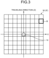
- FIG. 3 is a schematic diagram illustrating an example of partitioned region information 30.
- the partitioned region information 30 is information indicating a partitioned region B in the surroundings of the mobile object 10.
- the partitioned region information 30 is information indicating each of a plurality of partitioned regions B into which the surroundings of the mobile object 10 are partitioned.
- the partitioned regions B are, for example, individual regions acquired by partitioning a three-dimensional space S' (orthogonal coordinate space) surrounding the mobile object 10 into a plurality of regions in a grid. More specifically, the partitioned regions B are individual regions acquired by partitioning the three-dimensional space S' surrounding the mobile object 10 into a plurality of regions along a plane (XZ plane) orthogonal to the height direction (vertical direction).
- the orthogonal coordinate space is a three-dimensional space represented by an orthogonal coordinate system.
- a polar coordinate space described later is a three-dimensional space represented by a polar coordinate system.
- the partitioned regions B are not limited to any particular shape.
- the partitioned regions B have a rectangular shape.
- the partitioned regions B are not limited to a square shape.
- the partitioned regions B may have a rectangular shape, for example.
- the partitioned regions B may be equal to or larger than detection points in size which are acquired by the external sensor 10B. That is, the partitioned regions B may be the same as the detection points in size.
- each partitioned region B may have a size that can include a plurality of detection points. That is, the size of each partitioned region B may be the same as the size corresponding to the sensor resolution which is the maximum density of detection points that can be acquired by the external sensor 10B, or may be larger than the size corresponding to the sensor resolution.
- the maximum possible size of each partitioned region B may be appropriately adjusted according to the unit of the existence probabilities of obstacles.
- the processing unit 20A generates the partitioned region information 30 in advance.
- the processing unit 20A defines the three-dimensional space S'.
- This three-dimensional space S' is a three-dimensional orthogonal coordinate space with the mobile object 10 as the origin, the traveling direction of the mobile object 10 as the Z-axis, the height direction as the Y-axis, and the axis orthogonal to the Z-axis and the Y-axis as the X-axis.
- the processing unit 20A partitions this three-dimensional space S' into a grid along the XZ plane, thereby partitioning the surroundings of the mobile object 10 into the plurality of partitioned regions B.
- the processing unit 20A stores the partitioned region information 30 in the storage unit 20B in advance.
- the partitioned region information 30 indicates the position and the size of each of the partitioned regions B.
- an external apparatus may generate the partitioned region information 30.
- the information processing apparatus 20 may acquire the partitioned region information 30 from the external apparatus via the communication unit 10D and store the partitioned region information 30 in the storage unit 20B.
- the storage unit 20B stores the partitioned region information 30 in advance.
- the processing unit 20A includes a position acquisition unit 20C, a shape acquisition unit 20D, a calculation unit 20E, and an output control unit 20F.
- the position acquisition unit 20C, the shape acquisition unit 20D, the calculation unit 20E, and the output control unit 20F are implemented by one or a plurality of processors, for example.
- Each of the above units may be implemented by causing a processor such as a central processing unit (CPU) to execute a program, that is, software, for example.
- a processor such as a dedicated integrated circuit (IC), that is, hardware.
- IC dedicated integrated circuit
- Each of the above units may be implemented by using software and hardware in combination. In the case of using the plurality of processors, each processor may implement one of the units, or may implement two or more of the units.
- processor used in the present arrangement and arrangements described later refers to, for example, a CPU, a graphical processing unit (GPU), an application specific integrated circuit (ASIC), or a circuit of a programmable logic device (e.g., a simple programmable logic device (SPLD), a complex programmable logic device (CPLD), and a field programmable gate array (FPGA)).
- a programmable logic device e.g., a simple programmable logic device (SPLD), a complex programmable logic device (CPLD), and a field programmable gate array (FPGA)
- the processor implements each of the units above by reading and executing the program stored in the storage unit 20B. Note that instead of storing the program in the storage unit 20B, the program may be directly incorporated into the circuit of the processor. In this case, the processor implements each of the units above by reading and executing the program incorporated in the circuit.
- the position acquisition unit 20C acquires position-related information.
- the position-related information includes at least three-dimensional position information of the detection points.
- the position-related information includes the three-dimensional position information of the detection points, the partitioned region information 30, and the self position and attitude information.
- the position acquisition unit 20C acquires the three-dimensional position information of the detection points from the external sensor 10B. That is, the position acquisition unit 20C acquires the three-dimensional position information of each of the plurality of detection points detected by the external sensor 10B. Specifically, the position acquisition unit 20C acquires the three-dimensional position information for the detection points corresponding to the density of the detection points detectable by the external sensor 10B, that is, the number corresponding to the resolution of the external sensor 10B.
- the three-dimensional position information of the detection points is represented by polar coordinates, for example. Note that the external sensor 10B may acquire three-dimensional information of the detection points represented by orthogonal coordinates.
- the position acquisition unit 20C may acquire the three-dimensional position information of the detection points from the external apparatus.
- the position acquisition unit 20C may acquire the three-dimensional position information of the detection points from the external apparatus via the communication unit 10D.
- the position acquisition unit 20C acquires the partitioned region information 30 from the storage unit 20B. Note that the position acquisition unit 20C may acquire the partitioned region information 30 from the external apparatus via the communication unit 10D.
- the self position and attitude information is information indicating the three-dimensional position and attitude of the mobile object 10. That is, the self position and attitude information includes the three-dimensional position information and attitude information of the mobile object 10.
- the position acquisition unit 20C acquires the self position and attitude information from the internal sensor 10C. Note that the three-dimensional position information of the mobile object 10 is represented by world coordinates, for example.
- the position acquisition unit 20C outputs the position-related information to the shape acquisition unit 20D and the calculation unit 20E.
- the position-related information includes the three-dimensional position information of each of the plurality of detection points, the partitioned region information 30, and the self position and attitude information.
- the shape acquisition unit 20D acquires target surface shape information indicating the shape of a target surface.
- the target surface is a surface to be detected by the information processing apparatus 20.
- the target surface is a ground surface, a road surface, or a wall surface, for example. In the present arrangement, a description will be given of a case, as an example, where the target surface is the ground surface.
- the target surface shape information is information indicating the shape of the target surface.
- the target surface shape information is ground surface shape information indicating the shape of the ground surface.
- the shape acquisition unit 20D acquires the ground surface shape information of the ground surface.
- the shape acquisition unit 20D estimates the ground surface shape information according to the distribution of the detection points indicated by each of the plurality of three-dimensional position information received from the position acquisition unit 20C. Through this estimation, the shape acquisition unit 20D acquires the ground surface shape information.
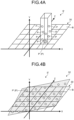
- FIGS. 4A, 4B , and 5 are explanatory diagrams of an example of estimation of ground surface shape information 36.
- the shape acquisition unit 20D arranges each detection point P in a corresponding position indicated by the three-dimensional position information, as illustrated in FIG. 4A .
- the three-dimensional position information indicates each detection point P in the three-dimensional space S' indicated by the partitioned region information 30. Note that in a case where the three-dimensional position information of the detection points P is represented by polar coordinates, the detection points P may be arranged in the three-dimensional space S' of the partitioned region information 30 following conversion into the orthogonal coordinates.
- FIG. 4A illustrates the detection points P arranged in a certain partitioned region B.
- the detection points P are arranged assuming that the position of the origin in the three-dimensional space S' indicated by the partitioned region information 30 is the current position of the mobile object 10.
- the shape acquisition unit 20D specifies one detection point P having the lowest height (the position in the Y-axis direction) as a representative detection point P (representative detection point P') for each of the plurality of partitioned regions B indicated by the partitioned region information 30. This is based on the assumption that the detection points P corresponding to the ground surface in a space surrounding the mobile object 10 exist at the lowest positions in the respective partitioned regions B. As illustrated in FIG. 4B , therefore, one detection point P is specified as a representative detection point P' for each of the plurality of partitioned regions B indicated by the partitioned region information 30.
- the shape acquisition unit 20D performs plane approximation for the representative detection points P' specified for the respective partitioned regions B in the partitioned region information 30.
- a RANdom SAmple Consensus (RANSAC) method is used, for example.
- the shape acquisition unit 20D randomly selects three representative detection points P' from the representative detection points P' corresponding to respective ones of the plurality of partitioned regions B. Then, a plane equation indicating an estimated plane 32 including the selected three representative detection points P' is calculated.
- the plane equation indicating the estimated plane 32 is represented by the following equation (1) .
- a, b, c, and d are coefficients representing the shape of the estimated plane 32.
- any representative detection points P' whose errors in the Y-axis direction relative to the estimated plane 32 are equal to or less than a predetermined threshold value Y TH are set as inliers by the shape acquisition unit 20D.
- the shape acquisition unit 20D counts the number of representative points P' set as inliers (hereinafter, referred to as the number of inliers).
- FIG. 5 is a schematic diagram illustrating a relationship between the estimated plane 32 and the representative detection points P' as inliers.
- the representative detection points P' as inliers among the representative detection points P' are indicated by circles.
- the representative detection points P' as inliers are representative detection points P' whose errors are equal to or less than the threshold value Y TH .
- the representative detection points P' as outliers are indicated by diamond marks in FIG. 5 .
- the representative detection points P' as outliers are representative detection points P' whose errors exceed the threshold value Y TH .
- the shape acquisition unit 20D repeats the series of processing the number of predetermined times while changing the combination of the selected representative detection points P'.
- the series of processing includes the selection of three representative detection points P' from the plurality of partitioned regions B, the calculation of the plane equation of the estimated plane 32, and the count of the number of inliers.
- the shape acquisition unit 20D acquires, as the ground surface shape information 36, the plane equation of the estimated plane 32 used for the calculation of the largest number of inliers.
- the shape acquisition unit 20D may acquire the ground surface shape information 36 using a method other than the plane approximation.
- the shape acquisition unit 20D may acquire the ground surface shape information 36 using curved surface approximation, or straight-line approximation or curved-line approximation in the YZ plane, for example.
- the shape acquisition unit 20D outputs the acquired ground surface shape information 36 to the calculation unit 20E.
- the description will continue, returning to FIG. 2 .
- the calculation unit 20E will be described.
- the calculation unit 20E calculates state information of an object.
- the object is an object to be detected by the information processing apparatus 20.
- the object is, for example, an obstacle or the like that obstructs the traveling of the mobile object 10.
- the object is not limited to an obstacle. In the present arrangement, a description will be given of a case, as an example, where the object whose state information is calculated by the calculation unit 20E is an obstacle.
- the state information is information indicating the state of the object.
- the state of the object is the existence probability of the object, the probability that the object does not exist, the occupation ratio of the object, or the probability that the object does not occupy, for example.
- the state information indicates the existence probability of the object, for example.
- the state information indicates the existence probability of an obstacle.
- the calculation unit 20E calculates the existence probability information indicating the existence probability of an obstacle.
- the existence probability is represented by a value in a range of 0.0 or more and 1.0 or less.
- the calculation unit 20E calculates the existence probability of an obstacle according to a first distance on the basis of the three-dimensional position information of the corresponding detection point P acquired from the position acquisition unit 20C and the ground surface shape information 36 acquired from the shape acquisition unit 20D.
- the first distance is a distance of the detection point P from the ground surface. In other words, the first distance is the height of the detection point P from the ground surface.
- the first distance is represented by a difference between the ground surface having the shape indicated by the ground surface shape information 36 and the position in the height direction (Y-axis direction) of the detection point P indicated by the three-dimensional position information.
- the first distance may be represented by the length of a perpendicular line drawn from the detection point P arranged at the position indicated by the three-dimensional position information down to the ground surface having the shape indicated by the ground surface shape information 36.
- the calculation unit 20E calculates the existence probability of an obstacle by calculating the first distance for the corresponding detection point P using the three-dimensional position information of the detection point P and the ground surface shape information 36.
- the calculation unit 20E calculates a lower existence probability as the first distance is shorter. In other words, the calculation unit 20E calculates a higher existence probability as the first distance is longer. Note that as the first distance is shorter, the position of the detection point P is closer to the ground surface. In addition, as the first distance is longer, the position of the detection point P is higher to the ground surface.
- the calculation unit 20E calculates a predetermined intermediate value as the existence probability.
- the intermediate value is an intermediate value of "0.5" between 0.0, which is the minimum value of the existence probability, and 1.0, which is the maximum value of the existence probability.
- the intermediate value indicates that the state is unknown.
- the processing unit 20A treats the region with the intermediate value of "0.5" as an "unknown region” whose state is unknown.
- the unknown state indicates a state that the processing unit 20A cannot confirm the existence probability due to shielding of an object or the like.
- the processing unit 20A treats the region with the minimum value of "0.0" of the existence probability as a "travelable region” where no obstacle exists.
- the processing unit 20A treats the region with the maximum value of "1.0" of the existence probability as an "occupied region” where an obstacle exists.
- the calculation unit 20E may calculate an existence probability that a second distance is included in addition to the first distance.
- the second distance indicates a distance between a reference position and the position of the detection point P indicated by the three-dimensional position information.
- the reference position is the current position of the mobile object 10 in which the information processing apparatus 20 is mounted. That is, the second distance is a distance between the position of the mobile object 10 and the position of the detection point P.
- the reference position may be referred to as the mobile object 10 or the position of the mobile object 10.
- the calculation unit 20E calculates the existence probability which is lower as the first distance is shorter, and is lower as the second distance is longer.
- the calculation unit 20E calculates the existence probability according to the first distance of a detection point P closest to the reference position in a corresponding angular direction ( ⁇ direction, which hereinafter may be referred to as an angular direction ⁇ ) from the reference position (position of the mobile object 10).
- the angular direction ⁇ is the direction of ⁇ which is an argument in polar coordinates. That is, the angular direction ⁇ indicates an orientation with the current position of the mobile object 10 as the origin on the plane orthogonal to the vertical direction.
- the calculation unit 20E identifies a detection point P which exists in the closest position to the mobile object 10 for each angular direction ⁇ from the mobile object 10. For the detection point P, the calculation unit 20E then calculates a lower existence probability as the first distance is shorter.
- the calculation unit 20E identifies a detection point P which exists in the closest position to the mobile object 10 for each angular direction ⁇ . For the identified detection point P, the calculation unit 20E then calculates a lower existence probability as the first distance of the detection point P is shorter. For the identified detection point P, as the first distance of the detection point P is shorter, the calculation unit 20E calculates a value closer to the intermediate value of "0.5" as the existence probability of an obstacle at the detection point P, for example.
- the calculation unit 20E calculates the existence probability which is lower as the first distance is shorter, and is lower as the second distance is longer. In other words, for the detection point P which exists in the closest position to the mobile object 10 for each angular direction ⁇ , the calculation unit 20E calculates the existence probability which is lower as the height from the ground surface (first distance) is shorter, and is lower as the distance from the mobile object 10 (second distance) is longer.
- the calculation unit 20E calculates a model indicating the change in the existence probability according to the distance from the position of the mobile object 10 as well as the existence probability of the detection point P which exists in the closest position to the mobile object 10 in the corresponding angular direction.
- the calculation unit 20E sets the existence probabilities of the minimum value in a direction approaching from the mobile object 10 to the detection point P closest to the mobile object 10 for each line along the corresponding angular direction ⁇ from the reference position with the mobile object 10 as a reference in the polar coordinate space. Furthermore, the calculation unit 20E sets a model indicating the existence probabilities along the line extending in the corresponding angular direction ⁇ with the mobile object 10 as a reference. In the model, as the distance is closer to the detection point P which is closest to the mobile object 10, the existence probabilities change from the minimum value to the existence probability of the detection point P. Furthermore, the calculation unit 20E calculates the existence probabilities such that a region far from the mobile object 10 than the detection point P closest to the mobile object 10 is set to the existence probability of the intermediate value.
- the calculation unit 20E calculates a model indicating the existence probabilities which smoothly change before and after the detection point P closest to the mobile object 10 along the corresponding line.
- the regions where the existence probabilities change smoothly may be set in advance.
- the calculation unit 20E may use a predetermined number of partitioned regions B other than and adjacent to a partitioned region B including the detection point P which exists in the closest position to the mobile object 10 for each of the angular directions ⁇ , for example.
- the calculation unit 20E calculates the existence probabilities that satisfy the above conditions by calculating the equations.
- the calculation unit 20E acquires the position-related information from the position acquisition unit 20C.
- the position-related information includes the three-dimensional position information of each of the plurality of detection points P, the partitioned region information 30, and the self position and attitude information.
- the calculation unit 20E extracts detection points P to be used for the calculation of the existence probabilities among the plurality of detection points P indicated by each of the plurality of pieces of three-dimensional position information acquired from the position acquisition unit 20C.
- FIG. 6 is an explanatory diagram illustrating an example of extraction of detection points P.
- the calculation unit 20E extracts detection point P located in a space within a predetermined range in a three-dimensional space as detection points P used for calculation of the existence probabilities.
- the traveling direction Z of the mobile object 10 is the central axis L.
- the central axis L is a long straight line that passes through a predetermined position in the mobile object 10 and that extends in a direction along the traveling direction Z of the mobile object 10.
- the predetermined position in the mobile object 10 is the center of the body of the mobile object 10, or the center in the height direction of a tire provided in the mobile object 10, for example.
- the external sensor 10B is mounted in the mobile object 10 such that the optical axis of the external sensor 10B matches the center of the mobile object 10 and the traveling direction Z.
- the optical axis of the external sensor 10B matches the central axis L.
- the calculation unit 20E uses the space of a predetermined range R as a space from which detection points P are extracted.
- the predetermined range R includes the central axis L and is centered on the central axis L.
- the space in this predetermined range is a region R that includes the central axis L and has a range of ⁇ R' in the vehicle height direction of the mobile object 10 with the central axis L as the center.
- the range of the region R is adjusted in advance such that the region does not include a ground surface G while the mobile object 10 is traveling. For example, the length in the vertical direction of the region R is less than the vehicle height T of the mobile object 10.
- the calculation unit 20E uses the optical axis of the external sensor 10B as the central axis L. Then, among the plurality of detection points P detected by the external sensor 10B, the calculation unit 20E extracts detection points P located in the predetermined range R as detection points P used for calculation of the existence probabilities.
- This processing excludes, for example, a detection point P indicated by a triangle and a detection point P indicated by a diamond from the calculation of the existence probabilities as illustrated in FIG. 6 . Then, a detection point P indicated by a circle is extracted for the calculation of the existence probability.
- the calculation unit 20E extracts the detection points P for the calculation of the existence probabilities among the plurality of detection points P included in the angle of view of the external sensor 10B. As a result, the calculation unit 20E extracts any detection point P that can be an obstacle to the traveling of the mobile object 10.
- the calculation unit 20E converts the three-dimensional position coordinates into polar coordinates.
- the following equations (2) and (3) are used, for example. Note that in a case where the three-dimensional position coordinates of the detection points P are represented by polar coordinates, this conversion processing is unnecessary.
- the calculation unit 20E obtains a plurality of detection points P for the calculation of the existence probabilities, which is represented by the three-dimensional position coordinates of the polar coordinates.
- FIG. 7 is a schematic diagram of detection points P represented by the three-dimensional position coordinates of the polar coordinates.
- FIG. 7 illustrates each of the detection points P measured in a scene where the mobile object 10 is reaching a T-intersection surrounded by fences.
- the calculation unit 20E identifies a detection point P located at the closest distance r to the mobile object 10 for each angular direction ⁇ indicated by the polar coordinates.
- FIG. 8 is a schematic diagram illustrating a polar coordinate space S1 surrounding the mobile object 10 for the scene in FIG. 7 .
- the polar coordinate space S1 is divided into nine in the angular direction ⁇ every 20°.
- the calculation unit 20E identifies a detection point P at the distance r closest to the mobile object 10.
- the distance r corresponds to the second distance.
- the calculation unit 20E calculates, for each angular direction ⁇ , the existence probability of an obstacle for each of a plurality of regions B' arranged along the respective angular directions ⁇ from the mobile object 10 by using the following equations (4) and (5).
- the regions B' are regions formed by dividing the polar coordinate space S1 into a plurality of regions. It is preferable that the regions B' are equal to or smaller than the above-described partitioned regions B in size.
- p(r) indicates a temporary existence probability of an obstacle.
- the temporary existence probability indicates a temporary value in the process of calculating the existence probability.
- the distance in the polar coordinates is indicated by r.
- the distance r from the origin in the polar coordinates to a detection point P closest to the mobile object 10 in the corresponding angular direction ⁇ to be processed is indicated by r 0 .
- the origin in the polar coordinates is derived from the self position and attitude information of the mobile object 10.
- ⁇ indicates a standard deviation in the depth direction of the three-dimensional position information acquired by the position acquisition unit 20C. ⁇ can be acquired in advance depending on the characteristics of the external sensor, and the value obtained in advance is used.
- p' (r) indicates the existence probability of an obstacle. A predetermined minimum value of the existence probability is indicated by P min . In the present arrangement, P min is "0.0".
- ⁇ is determined according to the first distance and the second distance of a detection point P which exists in the closest position to the mobile object 10 in the corresponding angular direction ⁇ to be processed.
- the first distance is the height of the detection point P from the ground surface.
- the second distance is the distance r 0 of the detection point P from the mobile object 10.
- the equation (4) includes the elements (r and r 0 ) indicating the distance (second distance) of the detection point P.
- the calculation unit 20E derives, for each angular direction ⁇ , ⁇ according to the first distance and the second distance of a detection point P which exists in the closest position to the mobile object 10 in the corresponding angular direction ⁇ . Then, the calculation unit 20E calculates, for each angular direction ⁇ , the existence probability p'(r) for each distance r from the mobile object 10 along each of the lines extending along the respective angular directions ⁇ by using the equations (4) and (5) above.
- the calculation unit 20E calculates the existence probabilities for each of the angular directions ⁇ with the mobile object 10 as a reference. In other words, the calculation unit 20E calculates the existence probability for each of the plurality of regions B' through which the line passes along each of the angular directions ⁇ with the mobile object 10 as a reference.
- the calculation unit 20E calculates ⁇ for each angular direction ⁇ indicated by the polar coordinates. For example, the calculation unit 20E divides the polar coordinate space S1 in front of the traveling direction of the mobile object 10 in the angular direction ⁇ every 20° (nine divisions). Then, the calculation unit 20E sets each angular direction ⁇ as a direction to be processed, and then performs the following processing.
- the coordinates of a detection point P closest to the mobile object 10 is set as (X i , Y i , Zi) by the calculation unit 20E. Furthermore, the calculation unit 20E acquires the plane equation indicating the ground surface shape information 36 calculated by the shape acquisition unit 20D. As described above, the plane equation is represented by the above equation (1).
- the calculation unit 20E subsequently calculates the first distance of the detection point P closest to the mobile object 10 (the detection point P at the distance r 0 ) in the corresponding angular direction ⁇ to be processed.
- the first distance is the distance from the ground surface.
- h 1 max 0.0 , Y i ⁇ ⁇ aX i ⁇ cZ i ⁇ d b
- h i indicates the first distance of the detection point P closest to the mobile object 10 (the detection point P at the distance r 0 ).
- the first distance is the distance from the ground surface.
- a, b, and c are similar to those in the above equation (1).
- X i , Y i , Z i are the coordinates of the detection point P closest to the mobile object 10 (i.e., the detection point P at the distance r 0 ).
- the calculation unit 20E calculates the value of ⁇ in the corresponding angular direction ⁇ to be processed by using the first distance h i acquired by the equation (6).
- the first distance h i is the distance, from the ground surface, of the detection point P (the detection point P at the distance r 0 ) closest to the mobile object 10 in the corresponding angular direction.
- ⁇ min max 0.5 h i h TH , 1.0
- h TH indicates a threshold value of the first distance of the detection point P from the ground surface.
- ⁇ becomes 1 according to the above equation (7). Furthermore, in a case where h i calculated by the equation (6) is less than the threshold value h TH (hi ⁇ h TH ), ⁇ becomes a value larger than 0.5 and less than 1 according to the above equation (7). The longer h i , the larger ⁇ becomes.
- h TH may be a predetermined fixed value. Furthermore, the calculation unit 20E may set the threshold value h TH according to the mobile object 10 and the distance r 0 between the mobile object 10 and the detection point P closest to the mobile object 10 in the corresponding angular direction ⁇ to be processed.
- the calculation unit 20E calculates the threshold value h TH using the following equation (8).
- h TH tan ⁇ th ⁇ r
- ⁇ th indicates a threshold value of the angle ⁇ of the detection point P with respect to the ZX plane in the polar coordinate space.
- ⁇ th indicates a threshold value of the angle ⁇ of the detection point P with respect to the ground surface with the mobile object 10 as the origin.
- r indicates the distance r 0 between the mobile object 10 and the detection point P closest to the mobile object 10 in the corresponding angular direction ⁇ to be processed.
- the calculation unit 20E calculates the threshold value h TH using the equation (8). In this way, the calculation unit 20E may calculate the threshold value h TH according to the distance r 0 between the mobile object 10 and the detection point P closest to the mobile object 10 in the corresponding angular direction ⁇ to be processed. Therefore, the longer the distance r 0 , the larger the threshold value h TH is used by the calculation unit 20E.
- the calculation unit 20E calculates ⁇ for each angular direction ⁇ to be processed by using the equations (6) and (7).
- ⁇ corresponds to the first distance (the distance from the ground surface) and the second distance (the distance r 0 from the mobile object 10) of the detection point P closest to the mobile object 10 in the corresponding angular direction ⁇ .
- the calculation unit 20E calculates, for each angular direction ⁇ to be processed, the existence probability of an obstacle using the calculated ⁇ for each of the regions B' along the respective angular directions by using the equations (4) and (5).
- the calculation unit 20E calculates the existence probability of an obstacle according to the conditions of the first distance and the second distance for each of the regions B' along the respective angular directions ⁇ .
- FIGS. 9 to 12 are schematic diagrams illustrating the existence probabilities calculated by the calculation unit 20E.
- FIG. 9 is a schematic diagram illustrating the plurality of extracted regions B' arranged along the angular direction "60°" in FIG. 8 .
- a partitioned region B'8(B') is a region B' at the distance r 0 that includes a detection point P closest to the mobile object 10.
- the calculation unit 20E calculates the existence probabilities represented by a model 50A by calculating the existence probabilities for the line along this angular direction ⁇ by using the above equations (4) to (8).
- the existence probabilities in the regions B' (B'1 to B'11) sequentially arranged along the angular direction ⁇ are represented by the model 50A which changes smoothly before and after the region B'8 including the detection point P closest to the mobile object 10. Furthermore, the existence probability of an obstacle in each region B' is a value corresponding to the first distance (the distance from the ground surface) of the detection point P, which exists in the closest position to the mobile object 10, and the second distance of the detection point P (the distance r 0 from the mobile object 10) in the corresponding angular direction ⁇ as a result of calculation using the above equations (4) to (8).
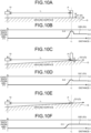
- FIG. 10A to FIG. 10F are explanatory diagrams illustrating examples of the existence probabilities of obstacles calculated by the calculation unit 20E.
- FIG. 10 A to FIG. 10F illustrate the examples of the existence probabilities of obstacles for a certain angular direction ⁇ in the polar coordinate space S1.
- FIG. 10A to FIG. 10F illustrate three different types of forms in which the distance r 0 to a detection point P closest to the mobile object 10 is the same but the height of the detection point P from the ground surface (first distance) is different from one another.
- FIG. 10B is a model 50B illustrating the existence probabilities of obstacles in a line along a certain angular direction ⁇ for a case where the first distance (the height from the ground surface G) of the detection point P closest to the mobile object 10 is D1 in this angular direction ⁇ (see FIG. 10A ).
- the first distance D1 is an example of the height which is sufficiently away from the ground surface.
- FIG. 10D is a model 50C illustrating the existence probabilities of obstacles in a line along a certain angular direction ⁇ for a case where the first distance (the height from the ground surface G) of the detection point P closest to the mobile object 10 is D2 in this angular direction ⁇ (see FIG. 10C).
- FIG. 10C is a state where the mobile object 10 is traveling uphill, for example.
- the first distance D2 is an example of the height which is lower than the first distance D1 and higher than the ground surface. That is, the illustrated relationship is the first distance D1 > the first distance D2 > 0.
- FIG. 10F is a model 50D illustrating the existence probabilities of obstacles in a line along a certain angular direction ⁇ for a case where the first distance (the height from the ground surface G) of the detection point P closest to the mobile object 10 is D3 in this angular direction ⁇ (see FIG. 10E).
- FIG. 10F is a state where the mobile object 10 is traveling downhill, for example.
- the calculation unit 20E calculates a lower existence probability for the detection point P by using the above equations (4) to (8). For this detection point P, for example, the calculation unit 20E calculates the existence probability of "0.8" in the case of the first distance D1, the existence probability of "0.6” in the case of the first distance D2, and the existence probability of "0.5” in the case of the first distance D3.
- the calculation unit 20E calculates, for each angular direction ⁇ , the existence probability of "0.0" of the obstacle toward the detection point P located at the closest distance r 0 from the position of the mobile object 10 in the corresponding angular direction ⁇ by using the above equations (4) to (8).
- the calculation unit 20E changes the existence probability toward the existence probability of the detection point P at the distance r 0 .
- the calculation unit 20E calculates the intermediate value of "0.5", which is an "unknown region", as the existence probability for a region B' at the distance r far from the mobile object 10 than the distance r 0 .
- the calculation unit 20E calculates the existence probabilities which change smoothly before and after the region B' including the detection point P closest to the mobile object 10. These are represented by the models 50B to 50D as the existence probabilities for the regions B' which sequentially exist in the line along the corresponding angular direction ⁇ .
- FIGS. 11A-1 to 11D-2 illustrate examples of the existence probabilities of obstacles for a certain angular direction ⁇ in the polar coordinate space S1.
- FIGS. 11A-1 to 11D-2 illustrate a plurality of forms in which the distance r 0 (second distance) to a detection point P closest to the mobile object 10 is different from one another.
- FIG. 11A-2 illustrates models 50 (a model 50E and a model 50F) illustrating two types of existence probabilities calculated using a corresponding one of two types of detection points P (a detection point P1, a detection point P2) located at different distances r 0 from the mobile object 10.
- a detection point P1, a detection point P2 located at different distances r 0 from the mobile object 10.
- FIG. 11A-1 assume a case where the distance r 0 of the detection point P1 closest to the mobile object 10 is r 01 and a case where the distance r 0 of the detection point P closest to the mobile object 10 is r 02 , for example. Note that the distance r 01 ⁇ distance r 02 is assumed.
- the first distances D which are the heights of these detection points P (the detection point P1 and the detection point P2) from the ground surface are the same.
- the calculation unit 20E calculates the model 50E representing the existence probabilities illustrated in FIG. 11A-2 by performing the above processing. In addition, in a case where the detection point P closest to the mobile object 10 is the detection point P2, the calculation unit 20E calculates the model 50F representing the existence probabilities illustrated in FIG. 11A-2 by performing the above processing.
- the calculation unit 20E calculates a lower existence probability for the detection point P which exists in the closest position to the mobile object 10 as the distance r 0 of the detection point P is longer.
- the calculation unit 20E can calculate the existence probability which corresponds to the angle ⁇ ( ⁇ 1 , ⁇ 2 ) of the detection point P to the ground surface with a point of intersection between a point immediately below the mobile object 10 and the ground surface as the origin by calculating the existence probability using the above equations (4) to (8).
- the detection point P is the one which exists in the closest position to the mobile object 10. That is, the larger the angle ⁇ , the higher the calculation unit 20E calculates the existence probability for the detection point P.
- the calculation unit 20E calculates, for each angular direction ⁇ , the existence probability of "0.0" of the obstacle toward the detection point P located at the closest distance r 0 from the position of the mobile object 10 in the corresponding angular direction ⁇ by using the above equations (4) to (8).
- the calculation unit 20E changes the existence probability toward the existence probability of the detection point P at the distance r 0 .
- the calculation unit 20E calculates the intermediate value of "0.5", which is an "unknown region", as the existence probability for a region B' at the distance r farther from the mobile object 10 than the distance r 0 .
- the calculation unit 20E can calculate the existence probability according to the conditions of the above-described first distance and second distance regardless of the orientation of the optical axis of the external sensor 10B by calculating the existence probability using the above equations (4) to (8).
- a model 50G in FIG. 11B-2 is a model 50 illustrating the existence probabilities in a certain angular direction ⁇ for a case where the first distance (the height from the ground surface) of a detection point P3 closest to the mobile object 10 is D4 and the distance r 0 is a distance r 01 (see FIG. 11B-1 ).
- a model 50I in FIG. 11 is a model 50 illustrating the existence probabilities in a certain angular direction ⁇ for a case where the first distance (the height from the ground surface) of a detection point P3 closest to the mobile object 10 is D4 and the distance r 0 is a distance r 01 (see FIG. 11B-1 ).
- 11B-2 is a model 50 illustrating the existence probabilities in a certain angular direction ⁇ for a case where the first distance (the height from the ground surface) of a detection point P4 closest to the mobile object 10 is D5 (where D4 > D5) and the distance r 0 is a distance r 02 (see FIG. 11B-1 ). Note that the illustrated relationship is r 01 ⁇ r 02 .
- the calculation unit 20E calculates the existence probability for the detection point P by using the above equations (4) to (8).
- the existence probability is lower as the first distance D of the detection point P which exists in the closest position to the mobile object 10 is shorter, and is lower as the second distance r 0 of the detection point P which exists in the closest position to the mobile object 10 is longer.
- the calculation unit 20E can calculate the existence probability according to the conditions of the above-described first distance and second distance regardless of the orientation of the optical axis of the external sensor 10B.
- the calculation unit 20E can calculate the existence probability according to the conditions of the above-described first distance and second distance regardless of the degree of inclination of the ground surface by calculating the existence probability using the above equations (4) to (8).
- a model 50J in FIG. 11C-2 is a model 50 illustrating the existence probabilities for a case where the first distance (the height from the ground surface) of a detection point P5 closest to the mobile object 10 is D6 and the distance r 0 is a distance r 01 (see FIG. 11C-1 ).
- a model 50L in FIG. 11D-2 is a model 50 illustrating the existence probabilities for a case where the first distance (the height from the ground surface) of a detection point P7 closest to the mobile object 10 is D8 and the distance r 0 is a distance r 01 (see FIG. 11D-1 ).
- a model 50M in FIG. 11D-2 is a model 50 illustrating the existence probabilities for a case where the first distance (the height from the ground surface) of a detection point P8 closest to the mobile object 10 is D9 (where D8 > D9) and the distance r 0 is a distance r 02 (see FIG. 11D-1 ). Note that the illustrated relationship is r 01 ⁇ r 02 .
- the calculation unit 20E calculates, for each angular direction ⁇ , the existence probability for the detection point P which exists in the closest position to the mobile object 10 by using the above equations (4) to (8).
- the existence probability for the detection point P is lower as the first distance (height) of the detection point P is shorter, and is lower as the second distance (distance r 0 ) of the detection point P is longer.
- the calculation unit 20E also calculates the existence probabilities of obstacles for the regions B' at the distances r other than the distance r 0 by using the above equations (4) and (5).
- the calculation unit 20E can calculate the existence probability according to the conditions of the above-described first distance and second distance regardless of the degree of inclination of the ground surface.
- the calculation unit 20E calculates the existence probabilities of obstacles for respective regions B'. That is, the calculation unit 20E calculates the existence probability of an obstacle for each of the regions B' by the above equations, using the distance r of the corresponding region B' from the mobile object 10 as well as the height (first distance), from the ground surface, of the closest detection point P in the corresponding angular direction ⁇ with the mobile object 10 as a reference and the distance r 0 (second distance) of this detection point P from the mobile object 10.
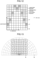
- FIG. 12 is a schematic diagram illustrating an example of a polar coordinate map M1.
- the polar coordinate map M1 represents the existence probability of an obstacle calculated by the calculation unit 20E for each of the regions B' in the polar coordinate space S1.
- the lateral direction (horizontal direction) indicates the angular direction ⁇ with the mobile object 10 as the origin in the polar coordinate space S1
- the longitudinal direction (vertical direction) indicates the distance r from the mobile object 10.
- FIG. 12 is an example where the polar coordinate space S1 in front of the traveling direction of the mobile object 10 is divided in the angular direction ⁇ every 20° (nine divisions).
- the polar coordinate map M1 illustrated in FIG. 12 can be obtained by the calculation unit 20E calculating the existence probabilities for each angular direction ⁇ using the method described above, for example.
- the calculation unit 20E converts the polar coordinate map M1 into an orthogonal coordinate space.
- FIG. 13 is a diagram illustrating a relationship between the regions B' in the polar coordinate space and the partitioned regions B in the orthogonal coordinate space. The relationship is illustrated in the orthogonal coordinate space.
- the regions indicated by the solid lines in FIG. 13 are the partitioned regions B divided into rectangles in the orthogonal coordinate space, and the regions indicated by the broken lines are the regions obtained by converting the regions B' divided into rectangles in the polar coordinate space into the orthogonal coordinate space.
- the calculation unit 20E For each partitioned region B in the orthogonal coordinate space, the calculation unit 20E sets the existence probability of an obstacle in the closest region B', among the regions B' rectangularly divided in the polar coordinate space, as the existence probability of an obstacle in the corresponding partitioned region B in the positional relationship as illustrated in FIG. 13 .
- the calculation unit 20E may perform this setting using a nearest-neighbor method.
- the calculation unit 20E interpolates, for each partitioned region B in the orthogonal coordinate space, the existence probability of an obstacle in the corresponding neighboring region B' among the regions B' rectangularly divided in the polar coordinate space.
- the existence probabilities of the obstacles in the partitioned regions B may be set in this way.
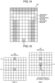
- FIG. 14 is a schematic diagram illustrating an example of an orthogonal coordinate map M2.
- FIG. 14 is a result obtained by converting the polar coordinate map M1 illustrated in FIG. 12 into the orthogonal coordinate map M2 which is in the orthogonal coordinate space.
- the existence probabilities of obstacles in the regions corresponding to the fences at the sides of the road on which the mobile object 10 travels are set to the maximum value or a value close to the maximum value in the orthogonal coordinate space (indicated by "grid-like hatching with diagonal lines” in FIG. 14 ). Furthermore, the existence probabilities of obstacles in the partitioned regions B further back than these regions are set to the intermediate value (indicated in "gray” in FIG. 14 ), and the state is unknown.
- the partitioned regions B existing between the regions where the obstacles exist and the mobile object 10 are set to the existence probabilities (indicated in a color between "grid-like hatching with diagonal lines” and “white” and “gray” in FIG. 14 ) that change toward the regions where the obstacles exist from the existence probabilities of obstacles of the minimum value (indicated in "white” in FIG. 14 ).
- the calculation unit 20E outputs this orthogonal coordinate map M2 to the output control unit 20F as existence probability information indicating the existence probabilities of obstacles.
- calculation unit 20E may integrate the calculated existence probability information of obstacles and the existence probability information of obstacles calculated in the past in time series.
- FIG. 15 is an explanatory diagram of the existence probabilities integrated in time series.
- FIG. 15 illustrates a plurality of partitioned regions B obtained by dividing a surrounding space centered on the mobile object 10 for each of time t-1 and time t.
- a region N t-1 which is a partitioned region B at the time t-1 and a region N t which is a partitioned region B at the time t are different in terms of the relative position from the mobile object 10 at each time. However, these of the region N t-1 and the region N t which is the partitioned region B at the time t indicate the same position in a world coordinate space.
- the calculation unit 20E calculates the moving amount of the mobile object 10 between the time t and the time t-1 from the self position and attitude information.
- the time t-1 is the time immediately before the time t.
- the calculation unit 20E obtains the partitioned regions B at the time t-1 corresponding to the respective partitioned regions B at the time t on the basis of the moving amount of the mobile object 10.
- the region N t-1 is obtained as the region (partitioned region B) at the time t-1 corresponding to the region N t at the time t.
- the calculation unit 20E integrates the existence probability of an obstacle for the region N t (the existence probability of the obstacle calculated on the basis of the current position information) and the existence probability of an obstacle calculated in the past for the region N t-1 .
- Bayes's theorem indicated in the following equation (9) may be used, for example.
- z t ) indicates the existence probability of an obstacle based on the current position information
- z 1 , ... ,z t-1 ) indicates the existence probability of an obstacle based on the position information in the past
- z i , ... ,z t ) indicates the existence probability of an obstacle based on the position information up to the present.
- the calculation unit 20E can robustly calculate the existence probabilities of obstacles even in a case where the sensor observes a value including a noise at any timing, for example.
- the calculation unit 20E outputs the calculated existence probability information indicating the existence probabilities of obstacles to the output control unit 20F.
- the calculation unit 20E outputs the orthogonal coordinate map M2 to the output control unit 20F.
- the orthogonal coordinate map M2 indicates the existence probability of an obstacle for each of the partitioned regions B.
- the output control unit 20F outputs the existence probability information.
- the orthogonal coordinate map M2 indicating the existence probability information is output to at least one of the output unit 10A and the power control unit 10G.
- the output control unit 20F displays the existence probability information on the display 10E.
- the output control unit 20F displays a display screen including the existence probability information on the display 10E.
- FIG. 16 is a schematic diagram illustrating an example of a display screen 70.
- the display screen 70 includes the orthogonal coordinate map M2 calculated by the calculation unit 20E.
- the orthogonal coordinate map M2 in the display screen 70 is the same as the orthogonal coordinate map M2 illustrated in FIG. 14 .
- the existence probabilities of obstacles in the regions corresponding to the fences at the sides of the road on which the mobile object 10 travels are indicated as regions 70E.
- the existence probabilities of obstacles further back than these regions are indicated as regions 70C to which the intermediate value is set.
- the partitioned regions B existing between regions where the obstacles exist and the mobile object 10 are indicated as regions 70A and regions 70B.
- the regions 70A are where the existence probabilities of obstacles indicate the minimum value.
- the regions 70B indicate the existence probabilities that change from the regions 70A toward the regions where the obstacles exist. Therefore, the user can easily recognize the existence probabilities of obstacles by confirming the display screen 70.
- the output control unit 20F may control the display 10E and the speaker 10F so as to output a sound and light indicating the existence probability information. Furthermore, the output control unit 20F may transmit the existence probability information to the external apparatus via the communication unit 10D.
- the output control unit 20F may output the existence probability information to the power control unit 10G.
- the power control unit 10G controls the power unit 10H according to the existence probability information received from the output control unit 20F.
- the power control unit 10G may generate a power control signal for controlling the power unit 10H according to the existence probability information and control the power unit 10H.
- the power control signal is a control signal for controlling the drive unit that drives the traveling of the mobile object 10 in the power unit 10H.
- the power control unit 10G controls steering, engine, and the like, of the mobile object 10 such that the mobile object 10 travels in regions of a real space corresponding to the partitioned regions B whose existence probabilities are indicated as travelable regions by the existence probability information.
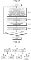
- FIG. 17 is a flowchart illustrating the example of the procedure of the information processing.
- the position acquisition unit 20C acquires position-related information (step S100).
- the shape acquisition unit 20D acquires ground surface shape information 36 indicating the shape of the ground surface (step S102).
- the calculation unit 20E calculates the existence probabilities of obstacles according to the first distances and the second distances of detection points P on the basis of the position-related information acquired in step S100 and the ground surface shape information 36 acquired in step S102 (step S104).
- the output control unit 20F outputs existence probability information calculated in step S104 (step S106).
- the orthogonal coordinate map M2 indicating the existence probability information is output to at least one of the output unit 10A and the power control unit 10G.
- step S108 determines whether to end the processing.
- step S108: No the determination in step S108 is negative (step S108: No)
- step S108: Yes the processing returns to step S100.
- step S108: Yes the determination in step S108 is positive (step S108: Yes)
- the information processing apparatus 20 includes the position acquisition unit 20C, the shape acquisition unit 20D, and the calculation unit 20E.
- the position acquisition unit 20C acquires three-dimensional position information of detection points P.
- the shape acquisition unit 20D acquires target surface shape information (ground surface shape information 36) indicating the shape of the target surface (ground surface).
- the calculation unit 20E calculates state information of objects (existence probabilities of obstacles) according to the first distances of the detection points P from the ground surface on the basis of the three-dimensional position information and the target surface shape information (ground surface shape information 36).
- the information processing apparatus 20 calculates the existence probabilities of obstacles (state information of objects) according to the distances of the detection points P from the ground surface (target surface). Accordingly, it is possible to suppress the occurrence that a travelable region such as a ground surface is erroneously recognized as an obstacle. More specifically, even in a case where a position indicated by the three-dimensional position information of a detection point P indicates a target surface such as a ground surface, it is possible to suppress the occurrence that the region including the detection point P is recognized as an object such as an obstacle.
- the information processing apparatus 20 according to the present arrangement can improve the reliability of object detection.
- the information processing apparatus 20 derives the first distances of the detection points P from the ground surface on the basis of the ground surface shape information 36. Therefore, it is possible to suppress the influence of estimation errors of the ground surface shape, thereby improving the reliability of the object detection.
- the position acquisition unit 20C acquires the three-dimensional position information of detection points P from the external sensor 10B, and the shape acquisition unit 20D generates the ground surface shape information 36 using this three-dimensional position information.
- the position acquisition unit 20C and the shape acquisition unit 20D may acquire the three-dimensional position information of the detection points P using different external sensors 10B.
- a first external sensor 10J and a second external sensor 10K may be included as the external sensors 10B as illustrated in FIG. 2 .
- the first external sensor 10J and the second external sensor 10K are similar to the external sensor 10B described above.
- the first external sensor 10J and the second external sensor 10K may be physically different sensors.
- the first external sensor 10J and the second external sensor 10K just need to be mutually different types of the external sensors 10B.
- a photographing apparatus (a monocular camera or a stereo camera) is used as the first external sensor 10J
- a laser imaging detection and ranging (LIDAR) sensor such as a two-dimensional LIDAR sensor or a three-dimensional LIDAR sensor mounted parallel to a horizontal plane is used as the second external sensor 10K.
- LIDAR laser imaging detection and ranging
- the position acquisition unit 20C acquires the three-dimensional position information of detection points P from the second external sensor 10K such as the LIDAR sensor and outputs the three-dimensional position information to the calculation unit 20E.
- the shape acquisition unit 20D may acquire the three-dimensional position information of the detection points P from the first external sensor 10J such as a camera and generate ground surface shape information 36. Then, the shape acquisition unit 20D may output the ground surface shape information 36 generated using the three-dimensional position information of the detection points P acquired from the first external sensor 10J to the calculation unit 20E.
- the processing of the calculation unit 20E and the output control unit 20F are similar to those in the above arrangement.
- the shape acquisition unit 20D may acquire the three-dimensional position information of the detection points P from the second external sensor 10K such as the LIDAR sensor and generate the ground surface shape information 36. Then, the position acquisition unit 20C may acquire the three-dimensional position information of the detection points P from the first external sensor 10J such as a camera and output the three-dimensional position information to the calculation unit 20E.
- the optical axis of the LIDAR may be horizontal to the traveling direction as illustrated in FIG. 11A-1 . Furthermore, the optical axis of the LIDAR may be inclined to the traveling direction as illustrated in FIG. 11B-1 . Furthermore, even in a case where the second external sensor 10K is the three-dimensional LIDAR capable of measuring the distance information of a plurality of lines, the information processing apparatus 20 can also recognize a surrounding environment on the basis of the existence probabilities of obstacles calculated for the distance information of each line.
- the position acquisition unit 20C and the shape acquisition unit 20D acquire the three-dimensional position information of the detection points P using the different external sensors 10B in this way.
- the information processing apparatus 20 can calculate the existence probabilities of obstacles by using the ground surface shape information estimated from another sensor.
- the information processing apparatus 20 can suppress erroneous detection of part of the ground surface such as a road as an obstacle, and suppress undetected obstacles.
- the position acquisition unit 20C acquires the three-dimensional position information of the detection points P from the external sensor 10B mounted in the mobile object 10. Furthermore, the shape acquisition unit 20D acquires the ground surface shape information 36 on the basis of the three-dimensional position information acquired from the external sensor 10B mounted in the mobile object 10.
- At least one of the position acquisition unit 20C and the shape acquisition unit 20D may acquire the three-dimensional position information of the detection points P from an external apparatus.
- at least one of the position acquisition unit 20C and the shape acquisition unit 20D may acquire the three-dimensional position information of the detection points P from the external apparatus via the communication unit 10D.
- the shape acquisition unit 20D may acquire the ground surface shape information 36 by receiving the ground surface shape information 36 from the external apparatus via the communication unit 10D.
- FIG. 18 is the example of the hardware configuration of the information processing apparatus 20 according to the above arrangement.
- the information processing apparatus 20 includes a control apparatus, storage apparatuses, an I/F unit 82, an output unit 80, an input unit 94, and a bus 96, and has a hardware configuration using a typical computer.
- the control apparatus is a CPU 86 or the like.
- the storage apparatuses are a read only memory (ROM) 88, a random access memory (RAM) 90, a hard disk drive (HDD) 92, and the like.
- the I/F unit 82 serves as an interface with various devices.
- the output unit 80 outputs various kinds of information such as output information.
- the input unit 94 receives user operations.
- the bus 96 connects above units.
- the CPU 86 reads a program from the ROM 88 onto the RAM 90 and executes the program so that the above units are performed on the computer.
- the program for executing the above processing to be executed by the information processing apparatus 20 according to the above arrangement may be stored in the HDD 92. Furthermore, the program for executing the above processing to be executed by the information processing apparatus 20 according to the above arrangement may be incorporated preliminarily and provided in the ROM 88.
- the program for executing the above processing to be executed by the information processing apparatus 20 according to the above arrangement may be stored and provided in the form of an installable or executable file as a computer program product in a computer-readable storage medium such as a compact disc read only memory (CD-ROM), a compact disc recordable (CD-R), a memory card, a digital versatile disk (DVD), or a flexible disk (FD).
- a computer-readable storage medium such as a compact disc read only memory (CD-ROM), a compact disc recordable (CD-R), a memory card, a digital versatile disk (DVD), or a flexible disk (FD).
- the program for executing the above processing to be executed by the information processing apparatus 20 according to the above arrangement may be stored on a computer connected to a network such as the Internet, and provided by being downloaded via the network.
- the program for executing the above processing to be executed by the information processing apparatus 20 according to the above arrangement may be provided or distributed via a network such as the Internet.
Landscapes
- Engineering & Computer Science (AREA)
- Radar, Positioning & Navigation (AREA)
- Remote Sensing (AREA)
- General Physics & Mathematics (AREA)
- Physics & Mathematics (AREA)
- Automation & Control Theory (AREA)
- Computer Vision & Pattern Recognition (AREA)
- Multimedia (AREA)
- Theoretical Computer Science (AREA)
- Transportation (AREA)
- Mechanical Engineering (AREA)
- Traffic Control Systems (AREA)
- Optical Radar Systems And Details Thereof (AREA)
- Geophysics And Detection Of Objects (AREA)
Description
- The present disclosure described herein relates to an information processing apparatus and an information processing method.
- A system that generates an obstacle map on the basis of position information of points acquired using a distance sensor such as a laser sensor is known. There have been some cases where such a system erroneously recognizes a point corresponding to a ground surface as a three-dimensional object, thereby erroneously detecting a region that can actually travel as an obstacle. Accordingly, there is disclosed a system that a point whose distance between the point measured by laser irradiation and an estimated road surface is equal to or less than a threshold value is determined to correspond to a road surface and then removed on the basis of the estimated road surface shape.
- Removing the point corresponding to the road surface, however, necessitates another sensor to determine an obstacle in a direction in which the point has been removed. Therefore, in a case where the accuracy of another sensor is low, the reliability of obstacle detection is low accordingly. Conventionally, furthermore, there has been some cases where a point on the road surface is erroneously detected as an obstacle in a case where the accuracy of estimation of the road surface shape is low. Conventionally, therefore, the reliability of object detection has been insufficient.
-
US 7741961 B1 relates to an obstacle detection and tracking system that identifies objects in the path of a vehicle equipped with the system and issues a visual, audible, and/or control system warning. The system includes a depth imaging system that acquires depth data from objects in the field of view of a detection zone encompassing at least a portion of the road to be driven upon. It is assumed most of the acquired data represents road plane information. Statistical analysis of the depth image data identifies in a 3D space at least one plane of the road being driven, after which identification threshold normal heights above and below the road plane are defined. Imaged objects within the detection zone that are higher or lower than a threshold normal are deemed of potential concern and will generate a warning to the vehicle operator or vehicle. -
-
FIG. 1 is a diagram illustrating a mobile object; -
FIG. 2 is a block diagram illustrating a configuration of the mobile object; -
FIG. 3 is a schematic diagram illustrating partitioned region information; -
FIGS. 4A and 4B are explanatory diagrams of estimated ground surface shape information; -
FIG. 5 is an explanatory diagram of the estimated ground surface shape information; -
FIG. 6 is an explanatory diagram of extraction of detection points; -
FIG. 7 is a schematic diagram of the detection points; -
FIG. 8 is a schematic diagram of a polar coordinate space; -
FIG. 9 is a schematic diagram illustrating existence probabilities; -
FIG. 10 is a schematic diagram illustrating existence probabilities; -
FIGS. 11A-1 to 11D-2 are schematic diagrams illustrating existence probabilities; -
FIG. 12 is a schematic diagram illustrating existence probabilities; -
FIG. 13 is a diagram illustrating a relationship between regions in the polar coordinate space and partitioned regions in an orthogonal coordinate space, the relationship being illustrated in the orthogonal coordinate space; -
FIG. 14 is schematic diagram illustrating an orthogonal coordinate map; -
FIG. 15 is an explanatory diagram of existence probabilities integrated in time series; -
FIG. 16 is a schematic diagram illustrating a display screen; -
FIG. 17 is a flowchart illustrating an example of a procedure of information processing; and -
FIG. 18 is a hardware configuration diagram. - According to an arrangement, an information processing apparatus includes a position acquisition unit, a shape acquisition unit and a calculation unit. The position acquisition unit acquires three-dimensional position information of a detection point. The shape acquisition unit acquires target surface shape information indicating a shape of a target surface. The calculation unit calculates state information of an object according to a first distance of the detection point from the target surface on the basis of the three-dimensional position information and the target surface shape information.
- An information processing apparatus, an information processing method, and a computer-readable medium will be described in detail below with reference to the accompanying drawings.
-
FIG. 1 is a diagram illustrating an example of amobile object 10 according to the present arrangement. - The
mobile object 10 includes aninformation processing apparatus 20, anoutput unit 10A, anexternal sensor 10B, aninternal sensor 10C, apower control unit 10G, and apower unit 10H. - The
information processing apparatus 20 is, for example, a dedicated or general-purpose computer. In the present arrangement, a description will be given of a case, as an example, where theinformation processing apparatus 20 is mounted in themobile object 10. - The
mobile object 10 is a movable object. Themobile object 10 is a vehicle, a hand truck, an object capable of flying (a manned airplane, an unmanned airplane (e.g., an unmanned aerial vehicle (UAV), a drone), or a robot, for example. Furthermore, themobile object 10 is a mobile object that travels through driving operation by a human, or a mobile object capable of automatically traveling (autonomously traveling) without driving operation by a human, for example. In the present arrangement, a description will be given of a case, as an example, where themobile object 10 is a vehicle. The vehicle is a two-wheeled automobile, a three-wheeled automobile, or a four-wheeled automobile, for example. In the present arrangement, a description will be given of a case, as an example, where the vehicle is a four-wheeled automobile capable of autonomously traveling. - The
information processing apparatus 20 is mounted in themobile object 10. - The
power unit 10H is a driving device mounted in themobile object 10. Thepower unit 10H is an engine, a motor, or a wheel, for example. - The
power control unit 10G controls thepower unit 10H. Thepower unit 10H is driven through the control of thepower control unit 10G. To automatically drive themobile object 10, thepower control unit 10G controls thepower unit 10H on the basis of information that can be acquired from theexternal sensor 10B and theinternal sensor 10C, and existence probability information derived from processing described later, for example. Through the control of thepower unit 10H, the accelerator amount, the brake amount, the steering angle, and the like of themobile object 10 are controlled. For example, thepower control unit 10G controls the vehicle so as to keep traveling in the current lane while avoiding an object such as an obstacle, and keep a predetermined distance or more from a vehicle traveling ahead. - The
output unit 10A outputs various kinds of information. In the present arrangement, theoutput unit 10A outputs the existence probability information derived by theinformation processing apparatus 20. Note that the existence probability information may be a binary value indicating existence or non-existence. The details of the existence probability information will be described later. - The
output unit 10A includes, for example, a communication function that transmits the existence probability information, a display function that displays the existence probability information, and a sound output function that outputs a sound indicating the existence probability information. For example, theoutput unit 10A includes at least one of acommunication unit 10D, adisplay 10E, and aspeaker 10F. Note that theoutput unit 10A including thecommunication unit 10D, thedisplay 10E, and thespeaker 10F will be described as an example in the present arrangement. - The
communication unit 10D transmits the existence probability information to another apparatus. For example, thecommunication unit 10D transmits the existence probability information to another apparatus via a publicly-known communication line. Thedisplay 10E displays the existence probability information. Thedisplay 10E is a publicly-known liquid crystal display (LCD), a projection apparatus, or a light, for example. Thespeaker 10F outputs a sound indicating the existence probability information. - The
external sensor 10B is a sensor that recognizes the external world surrounding themobile object 10. Theexternal sensor 10B may be mounted in themobile object 10 or may be mounted outside of themobile object 10. The outside of themobile object 10 indicates another mobile object or an external apparatus, for example. - The surroundings of the
mobile object 10 are a region within a predetermined range from themobile object 10. This range is an observable range of theexternal sensor 10B. This range may be set in advance. - The
external sensor 10B acquires observation information of the external world. The observation information is information indicating a result of observation of the surroundings of the position in which theexternal sensor 10B is mounted. In the present arrangement, the observation information is information from which three-dimensional position information of each of a plurality of detection points in the surroundings of theexternal sensor 10B (i.e., the mobile object 10) can be derived. - The three-dimensional position information of a detection point is information indicating a three-dimensional position of the detection point in a real space. For example, the three-dimensional position information of the detection point is information indicating a distance from the
external sensor 10B to the detection point and a direction of the detection point relative to theexternal sensor 10B as a reference. These distance and direction can be represented by positional coordinates indicating the relative position of the detection point with respect to theexternal sensor 10B as a reference, positional coordinates indicating the absolute position of the detection point, or vectors, for example. Specifically, the three-dimensional position information is represented by polar coordinates or orthogonal coordinates. - Each detection point indicates an individual point which is individually observed by the
external sensor 10B in the external world of themobile object 10. For example, theexternal sensor 10B irradiates the surroundings of theexternal sensor 10B with light and receives reflected light that is reflected off a reflection point. This reflection point corresponds to a detection point. Note that a plurality of reflection points may be used as one detection point. - The
external sensor 10B acquires the observation information including a light irradiation direction for each of the plurality of detection points (the directions of the detection points relative to theexternal sensor 10B as a reference) and information on the reflected light that is reflected off each of the plurality of detection points. The information on the reflected light includes the elapsed time from the light irradiation to the reception of the reflected light and the intensity of the received light (or the attenuation ratio of the intensity of the received light to the intensity of the irradiated light), for example. - Then, the
external sensor 10B derives the three-dimensional position information of the detection points by using this elapsed time and the like, and outputs the three-dimensional position information to theinformation processing apparatus 20. Note that theinformation processing apparatus 20 may derive the three-dimensional position information of the detection points from the observation information. In the present arrangement, a description will be given of a case where theexternal sensor 10B outputs the three-dimensional position information of each of the detection points to theinformation processing apparatus 20. - The
external sensor 10B is a photographing apparatus, a distance sensor (a millimeter wave radar, a laser sensor), or a sonar sensor or an ultrasonic sensor that detects an object using sound waves, for example. The photographing apparatus acquires photographed image data (hereinafter, referred to as a photographed image) by photographing. The photographing apparatus is a stereo camera, a position specifying camera, or the like. The photographed image is digital image data defining a pixel value for each pixel, a depth map defining a distance from theexternal sensor 10B for each pixel, or the like. The laser sensor is a two-dimensional laser imaging detection and ranging (LIDAR) sensor or a three-dimensional LIDAR sensor, which is mounted parallel to a horizontal plane, for example. - In the present arrangement, a description will be given of a case, as an example, where the
external sensor 10B is a photographing apparatus. Note that in a case where theexternal sensor 10B is a monocular camera, theexternal sensor 10B may acquire the three-dimensional position information of detection points on the basis of changes of the photographed images corresponding to the movement of themobile object 10 using Structure from Motion or the like. In addition, in a case where theexternal sensor 10B is a stereo camera, theexternal sensor 10B may acquire the three-dimensional position information of detection points using parallax information between cameras. - In the present arrangement, a description will be given of a case, as an example, where the
external sensor 10B is mounted such that the photographing direction is the traveling direction of themobile object 10. In the present arrangement, therefore, a description will be given of a case where theexternal sensor 10B acquires the three-dimensional position information of each of detection points in the traveling direction (i.e., the front side) of themobile object 10. - The
internal sensor 10C is a sensor that observes the information of themobile object 10 itself. Theinternal sensor 10C acquires the three-dimensional position information of themobile object 10 as well as self position and attitude information that indicates the attitude of themobile object 10. Theinternal sensor 10C is an inertial measurement unit (IMU), a speed sensor, or a global positioning system (GPS), for example. The IMU acquires triaxial acceleration, triaxial angular velocity, and the like of themobile object 10. Note that the three-dimensional position information of themobile object 10 is represented by world coordinates. - Next, the electrical configuration of the
mobile object 10 will be described in detail.FIG. 2 is a block diagram illustrating an exemplary configuration of themobile object 10. - The
mobile object 10 includes theinformation processing apparatus 20, theoutput unit 10A, theexternal sensor 10B, theinternal sensor 10C, thepower control unit 10G, and thepower unit 10H. As described above, theoutput unit 10A includes thecommunication unit 10D, thedisplay 10E, and thespeaker 10F. - The
information processing apparatus 20, theoutput unit 10A, theexternal sensor 10B, theinternal sensor 10C, and thepower control unit 10G are connected via a bus 10I. Thepower unit 10H is connected to thepower control unit 10G. - The
information processing apparatus 20 includes astorage unit 20B and aprocessing unit 20A. In other words, theoutput unit 10A, theexternal sensor 10B, theinternal sensor 10C, and thepower control unit 10G, theprocessing unit 20A, and thestorage unit 20B are connected via thebus 101. - Note that at least one of the
storage unit 20B, theoutput unit 10A (thecommunication unit 10D, thedisplay 10E, and thespeaker 10F), theexternal sensor 10B, theinternal sensor 10C, and thepower control unit 10G may be connected to theprocessing unit 20A by wire or wirelessly. In addition, at least one of thestorage unit 20B, theoutput unit 10A (thecommunication unit 10D, thedisplay 10E, and thespeaker 10F), theexternal sensor 10B, theinternal sensor 10C, and thepower control unit 10G may be connected to theprocessing unit 20A via a network. - The
storage unit 20B stores various kinds of data. Thestorage unit 20B is a random access memory (RAM), a semiconductor memory device such as a flash memory, a hard disk, or an optical disk, for example. Note that thestorage unit 20B may be a storage apparatus that is provided outside theinformation processing apparatus 20. Furthermore, thestorage unit 20B may be a storage medium. Specifically, the storage medium may be a medium in which programs or various kinds of information is downloaded via a local area network (LAN), the Internet, or the like and are stored or temporarily stored. Furthermore, a plurality of storage mediums may constitute thestorage unit 20B. - In the present arrangement, the
storage unit 20B stores partitioned region information in advance.FIG. 3 is a schematic diagram illustrating an example of partitionedregion information 30. - The partitioned
region information 30 is information indicating a partitioned region B in the surroundings of themobile object 10. In the present arrangement, the partitionedregion information 30 is information indicating each of a plurality of partitioned regions B into which the surroundings of themobile object 10 are partitioned. The partitioned regions B are, for example, individual regions acquired by partitioning a three-dimensional space S' (orthogonal coordinate space) surrounding themobile object 10 into a plurality of regions in a grid. More specifically, the partitioned regions B are individual regions acquired by partitioning the three-dimensional space S' surrounding themobile object 10 into a plurality of regions along a plane (XZ plane) orthogonal to the height direction (vertical direction). Note that the orthogonal coordinate space is a three-dimensional space represented by an orthogonal coordinate system. In addition, a polar coordinate space described later is a three-dimensional space represented by a polar coordinate system. - The partitioned regions B are not limited to any particular shape. For example, the partitioned regions B have a rectangular shape. In addition, the partitioned regions B are not limited to a square shape. The partitioned regions B may have a rectangular shape, for example.
- Note that the partitioned regions B may be equal to or larger than detection points in size which are acquired by the
external sensor 10B. That is, the partitioned regions B may be the same as the detection points in size. In addition, each partitioned region B may have a size that can include a plurality of detection points. That is, the size of each partitioned region B may be the same as the size corresponding to the sensor resolution which is the maximum density of detection points that can be acquired by theexternal sensor 10B, or may be larger than the size corresponding to the sensor resolution. In addition, the maximum possible size of each partitioned region B may be appropriately adjusted according to the unit of the existence probabilities of obstacles. - In the present arrangement, a description will be given of a case where the partitioned regions B are larger than detection points in size which are acquired by the
external sensor 10B. In the present arrangement, therefore, a description will be given of a case, as an example, where a plurality of detection points is included in one partitioned region B. - The
processing unit 20A generates the partitionedregion information 30 in advance. For example, theprocessing unit 20A defines the three-dimensional space S'. This three-dimensional space S' is a three-dimensional orthogonal coordinate space with themobile object 10 as the origin, the traveling direction of themobile object 10 as the Z-axis, the height direction as the Y-axis, and the axis orthogonal to the Z-axis and the Y-axis as the X-axis. Then, theprocessing unit 20A partitions this three-dimensional space S' into a grid along the XZ plane, thereby partitioning the surroundings of themobile object 10 into the plurality of partitioned regions B. Then, theprocessing unit 20A stores the partitionedregion information 30 in thestorage unit 20B in advance. The partitionedregion information 30 indicates the position and the size of each of the partitioned regions B. - Note that an external apparatus may generate the partitioned
region information 30. In this case, theinformation processing apparatus 20 may acquire the partitionedregion information 30 from the external apparatus via thecommunication unit 10D and store the partitionedregion information 30 in thestorage unit 20B. In the present arrangement, thestorage unit 20B stores the partitionedregion information 30 in advance. - The description will continue, returning to
FIG. 2 . Theprocessing unit 20A includes aposition acquisition unit 20C, ashape acquisition unit 20D, acalculation unit 20E, and anoutput control unit 20F. Theposition acquisition unit 20C, theshape acquisition unit 20D, thecalculation unit 20E, and theoutput control unit 20F are implemented by one or a plurality of processors, for example. Each of the above units may be implemented by causing a processor such as a central processing unit (CPU) to execute a program, that is, software, for example. Each of the above units may be implemented by a processor such as a dedicated integrated circuit (IC), that is, hardware. Each of the above units may be implemented by using software and hardware in combination. In the case of using the plurality of processors, each processor may implement one of the units, or may implement two or more of the units. - Note that the term "processor" used in the present arrangement and arrangements described later refers to, for example, a CPU, a graphical processing unit (GPU), an application specific integrated circuit (ASIC), or a circuit of a programmable logic device (e.g., a simple programmable logic device (SPLD), a complex programmable logic device (CPLD), and a field programmable gate array (FPGA)).
- The processor implements each of the units above by reading and executing the program stored in the
storage unit 20B. Note that instead of storing the program in thestorage unit 20B, the program may be directly incorporated into the circuit of the processor. In this case, the processor implements each of the units above by reading and executing the program incorporated in the circuit. - The
position acquisition unit 20C acquires position-related information. The position-related information includes at least three-dimensional position information of the detection points. In the present arrangement, the position-related information includes the three-dimensional position information of the detection points, the partitionedregion information 30, and the self position and attitude information. - The
position acquisition unit 20C acquires the three-dimensional position information of the detection points from theexternal sensor 10B. That is, theposition acquisition unit 20C acquires the three-dimensional position information of each of the plurality of detection points detected by theexternal sensor 10B. Specifically, theposition acquisition unit 20C acquires the three-dimensional position information for the detection points corresponding to the density of the detection points detectable by theexternal sensor 10B, that is, the number corresponding to the resolution of theexternal sensor 10B. The three-dimensional position information of the detection points is represented by polar coordinates, for example. Note that theexternal sensor 10B may acquire three-dimensional information of the detection points represented by orthogonal coordinates. - Note that the
position acquisition unit 20C may acquire the three-dimensional position information of the detection points from the external apparatus. In this case, theposition acquisition unit 20C may acquire the three-dimensional position information of the detection points from the external apparatus via thecommunication unit 10D. - Furthermore, the
position acquisition unit 20C acquires the partitionedregion information 30 from thestorage unit 20B. Note that theposition acquisition unit 20C may acquire the partitionedregion information 30 from the external apparatus via thecommunication unit 10D. - The self position and attitude information is information indicating the three-dimensional position and attitude of the
mobile object 10. That is, the self position and attitude information includes the three-dimensional position information and attitude information of themobile object 10. In the present arrangement, theposition acquisition unit 20C acquires the self position and attitude information from theinternal sensor 10C. Note that the three-dimensional position information of themobile object 10 is represented by world coordinates, for example. - Then, the
position acquisition unit 20C outputs the position-related information to theshape acquisition unit 20D and thecalculation unit 20E. The position-related information includes the three-dimensional position information of each of the plurality of detection points, the partitionedregion information 30, and the self position and attitude information. - Next, the
shape acquisition unit 20D will be described. Theshape acquisition unit 20D acquires target surface shape information indicating the shape of a target surface. - The target surface is a surface to be detected by the
information processing apparatus 20. The target surface is a ground surface, a road surface, or a wall surface, for example. In the present arrangement, a description will be given of a case, as an example, where the target surface is the ground surface. - The target surface shape information is information indicating the shape of the target surface. In the present arrangement, a description will be given of a case, as an example, where the target surface shape information is ground surface shape information indicating the shape of the ground surface. In the present arrangement, therefore, a description will be given of a case, as an example, where the
shape acquisition unit 20D acquires the ground surface shape information of the ground surface. - In the present arrangement, the
shape acquisition unit 20D estimates the ground surface shape information according to the distribution of the detection points indicated by each of the plurality of three-dimensional position information received from theposition acquisition unit 20C. Through this estimation, theshape acquisition unit 20D acquires the ground surface shape information. -
FIGS. 4A, 4B , and5 are explanatory diagrams of an example of estimation of groundsurface shape information 36. - For example, the
shape acquisition unit 20D arranges each detection point P in a corresponding position indicated by the three-dimensional position information, as illustrated inFIG. 4A . The three-dimensional position information indicates each detection point P in the three-dimensional space S' indicated by the partitionedregion information 30. Note that in a case where the three-dimensional position information of the detection points P is represented by polar coordinates, the detection points P may be arranged in the three-dimensional space S' of the partitionedregion information 30 following conversion into the orthogonal coordinates. -
FIG. 4A illustrates the detection points P arranged in a certain partitioned region B. For example, the detection points P are arranged assuming that the position of the origin in the three-dimensional space S' indicated by the partitionedregion information 30 is the current position of themobile object 10. - Then, the
shape acquisition unit 20D specifies one detection point P having the lowest height (the position in the Y-axis direction) as a representative detection point P (representative detection point P') for each of the plurality of partitioned regions B indicated by the partitionedregion information 30. This is based on the assumption that the detection points P corresponding to the ground surface in a space surrounding themobile object 10 exist at the lowest positions in the respective partitioned regions B. As illustrated inFIG. 4B , therefore, one detection point P is specified as a representative detection point P' for each of the plurality of partitioned regions B indicated by the partitionedregion information 30. - Next, the
shape acquisition unit 20D performs plane approximation for the representative detection points P' specified for the respective partitioned regions B in the partitionedregion information 30. For plane approximation, a RANdom SAmple Consensus (RANSAC) method is used, for example. - Specifically, the
shape acquisition unit 20D randomly selects three representative detection points P' from the representative detection points P' corresponding to respective ones of the plurality of partitioned regions B. Then, a plane equation indicating an estimatedplane 32 including the selected three representative detection points P' is calculated. The plane equation indicating the estimatedplane 32 is represented by the following equation (1) .
- In the equation (1), a, b, c, and d are coefficients representing the shape of the estimated
plane 32. - Subsequently, any representative detection points P' whose errors in the Y-axis direction relative to the estimated
plane 32 are equal to or less than a predetermined threshold value YTH are set as inliers by theshape acquisition unit 20D. Then, theshape acquisition unit 20D counts the number of representative points P' set as inliers (hereinafter, referred to as the number of inliers). -
FIG. 5 is a schematic diagram illustrating a relationship between the estimatedplane 32 and the representative detection points P' as inliers. InFIG. 5 , the representative detection points P' as inliers among the representative detection points P' are indicated by circles. The representative detection points P' as inliers are representative detection points P' whose errors are equal to or less than the threshold value YTH. In addition, the representative detection points P' as outliers are indicated by diamond marks inFIG. 5 . The representative detection points P' as outliers are representative detection points P' whose errors exceed the threshold value YTH. - Then, the
shape acquisition unit 20D repeats the series of processing the number of predetermined times while changing the combination of the selected representative detection points P'. The series of processing includes the selection of three representative detection points P' from the plurality of partitioned regions B, the calculation of the plane equation of the estimatedplane 32, and the count of the number of inliers. Then, theshape acquisition unit 20D acquires, as the groundsurface shape information 36, the plane equation of the estimatedplane 32 used for the calculation of the largest number of inliers. - Note that the
shape acquisition unit 20D may acquire the groundsurface shape information 36 using a method other than the plane approximation. Theshape acquisition unit 20D may acquire the groundsurface shape information 36 using curved surface approximation, or straight-line approximation or curved-line approximation in the YZ plane, for example. - The
shape acquisition unit 20D outputs the acquired groundsurface shape information 36 to thecalculation unit 20E. - The description will continue, returning to
FIG. 2 . Next, thecalculation unit 20E will be described. Thecalculation unit 20E calculates state information of an object. - The object is an object to be detected by the
information processing apparatus 20. The object is, for example, an obstacle or the like that obstructs the traveling of themobile object 10. Note that the object is not limited to an obstacle. In the present arrangement, a description will be given of a case, as an example, where the object whose state information is calculated by thecalculation unit 20E is an obstacle. - The state information is information indicating the state of the object. The state of the object is the existence probability of the object, the probability that the object does not exist, the occupation ratio of the object, or the probability that the object does not occupy, for example. The state information indicates the existence probability of the object, for example.
- In the present arrangement, a description will be given of a case, as an example, where the state information indicates the existence probability of an obstacle. In the present arrangement, therefore, a description will be given of a case, as an example, where the
calculation unit 20E calculates the existence probability information indicating the existence probability of an obstacle. The existence probability is represented by a value in a range of 0.0 or more and 1.0 or less. - The
calculation unit 20E calculates the existence probability of an obstacle according to a first distance on the basis of the three-dimensional position information of the corresponding detection point P acquired from theposition acquisition unit 20C and the groundsurface shape information 36 acquired from theshape acquisition unit 20D. - The first distance is a distance of the detection point P from the ground surface. In other words, the first distance is the height of the detection point P from the ground surface.
- Specifically, the first distance is represented by a difference between the ground surface having the shape indicated by the ground
surface shape information 36 and the position in the height direction (Y-axis direction) of the detection point P indicated by the three-dimensional position information. Note that the first distance may be represented by the length of a perpendicular line drawn from the detection point P arranged at the position indicated by the three-dimensional position information down to the ground surface having the shape indicated by the groundsurface shape information 36. - In the present arrangement, the
calculation unit 20E calculates the existence probability of an obstacle by calculating the first distance for the corresponding detection point P using the three-dimensional position information of the detection point P and the groundsurface shape information 36. - The
calculation unit 20E calculates a lower existence probability as the first distance is shorter. In other words, thecalculation unit 20E calculates a higher existence probability as the first distance is longer. Note that as the first distance is shorter, the position of the detection point P is closer to the ground surface. In addition, as the first distance is longer, the position of the detection point P is higher to the ground surface. - Note that in a case where the first distance is equal to or less than 0, the
calculation unit 20E calculates a predetermined intermediate value as the existence probability. The intermediate value is an intermediate value of "0.5" between 0.0, which is the minimum value of the existence probability, and 1.0, which is the maximum value of the existence probability. The intermediate value indicates that the state is unknown. - In the present arrangement, the
processing unit 20A treats the region with the intermediate value of "0.5" as an "unknown region" whose state is unknown. The unknown state indicates a state that theprocessing unit 20A cannot confirm the existence probability due to shielding of an object or the like. In the present arrangement, furthermore, theprocessing unit 20A treats the region with the minimum value of "0.0" of the existence probability as a "travelable region" where no obstacle exists. In addition, theprocessing unit 20A treats the region with the maximum value of "1.0" of the existence probability as an "occupied region" where an obstacle exists. - Therefore, as the existence probability approaches the maximum value of "1.0" from the intermediate value of "0.5", this indicates the increasing possibility of approaching the "occupied region" from the "unknown region". In addition, as the existence probability approaches the minimum value of "0.0" from the intermediate value of "0.5", this indicates the increasing possibility of approaching the "travelable region" from the "unknown region".
- Note that the
calculation unit 20E may calculate an existence probability that a second distance is included in addition to the first distance. The second distance indicates a distance between a reference position and the position of the detection point P indicated by the three-dimensional position information. The reference position is the current position of themobile object 10 in which theinformation processing apparatus 20 is mounted. That is, the second distance is a distance between the position of themobile object 10 and the position of the detection point P. In the following description, the reference position may be referred to as themobile object 10 or the position of themobile object 10. - In the present arrangement, the
calculation unit 20E calculates the existence probability which is lower as the first distance is shorter, and is lower as the second distance is longer. - Specifically, the
calculation unit 20E calculates the existence probability according to the first distance of a detection point P closest to the reference position in a corresponding angular direction (φ direction, which hereinafter may be referred to as an angular direction φ) from the reference position (position of the mobile object 10). The angular direction φ is the direction of φ which is an argument in polar coordinates. That is, the angular direction φ indicates an orientation with the current position of themobile object 10 as the origin on the plane orthogonal to the vertical direction. - First, the
calculation unit 20E identifies a detection point P which exists in the closest position to themobile object 10 for each angular direction φ from themobile object 10. For the detection point P, thecalculation unit 20E then calculates a lower existence probability as the first distance is shorter. - Specifically, the
calculation unit 20E identifies a detection point P which exists in the closest position to themobile object 10 for each angular direction φ. For the identified detection point P, thecalculation unit 20E then calculates a lower existence probability as the first distance of the detection point P is shorter. For the identified detection point P, as the first distance of the detection point P is shorter, thecalculation unit 20E calculates a value closer to the intermediate value of "0.5" as the existence probability of an obstacle at the detection point P, for example. - For this detection point P, in the present arrangement, the
calculation unit 20E calculates the existence probability which is lower as the first distance is shorter, and is lower as the second distance is longer. In other words, for the detection point P which exists in the closest position to themobile object 10 for each angular direction φ, thecalculation unit 20E calculates the existence probability which is lower as the height from the ground surface (first distance) is shorter, and is lower as the distance from the mobile object 10 (second distance) is longer. - Then, along a line extending in the angular direction φ from the position of the
mobile object 10 in the polar coordinate space, thecalculation unit 20E calculates a model indicating the change in the existence probability according to the distance from the position of themobile object 10 as well as the existence probability of the detection point P which exists in the closest position to themobile object 10 in the corresponding angular direction. - For example, the
calculation unit 20E sets the existence probabilities of the minimum value in a direction approaching from themobile object 10 to the detection point P closest to themobile object 10 for each line along the corresponding angular direction φ from the reference position with themobile object 10 as a reference in the polar coordinate space. Furthermore, thecalculation unit 20E sets a model indicating the existence probabilities along the line extending in the corresponding angular direction φ with themobile object 10 as a reference. In the model, as the distance is closer to the detection point P which is closest to themobile object 10, the existence probabilities change from the minimum value to the existence probability of the detection point P. Furthermore, thecalculation unit 20E calculates the existence probabilities such that a region far from themobile object 10 than the detection point P closest to themobile object 10 is set to the existence probability of the intermediate value. - At this time, it is preferable that for each line extending in the corresponding angular direction φ from the reference position with the
mobile object 10 as a reference in the polar coordinate space, thecalculation unit 20E calculates a model indicating the existence probabilities which smoothly change before and after the detection point P closest to themobile object 10 along the corresponding line. The regions where the existence probabilities change smoothly may be set in advance. As the regions where the existence probabilities smoothly change, thecalculation unit 20E may use a predetermined number of partitioned regions B other than and adjacent to a partitioned region B including the detection point P which exists in the closest position to themobile object 10 for each of the angular directions φ, for example. - In the present arrangement, the
calculation unit 20E calculates the existence probabilities that satisfy the above conditions by calculating the equations. - Hereinafter, a further detailed description will be given of the calculation of the existence probabilities by the
calculation unit 20E in the present arrangement. - First, the
calculation unit 20E acquires the position-related information from theposition acquisition unit 20C. As described above, the position-related information includes the three-dimensional position information of each of the plurality of detection points P, the partitionedregion information 30, and the self position and attitude information. - Subsequently, the
calculation unit 20E extracts detection points P to be used for the calculation of the existence probabilities among the plurality of detection points P indicated by each of the plurality of pieces of three-dimensional position information acquired from theposition acquisition unit 20C. -
FIG. 6 is an explanatory diagram illustrating an example of extraction of detection points P. Among the plurality of detection points P, thecalculation unit 20E extracts detection point P located in a space within a predetermined range in a three-dimensional space as detection points P used for calculation of the existence probabilities. In the predetermined range, the traveling direction Z of themobile object 10 is the central axis L. The central axis L is a long straight line that passes through a predetermined position in themobile object 10 and that extends in a direction along the traveling direction Z of themobile object 10. The predetermined position in themobile object 10 is the center of the body of themobile object 10, or the center in the height direction of a tire provided in themobile object 10, for example. - For example, assume that the
external sensor 10B is mounted in themobile object 10 such that the optical axis of theexternal sensor 10B matches the center of themobile object 10 and the traveling direction Z. In this case, the optical axis of theexternal sensor 10B matches the central axis L. - Then, the
calculation unit 20E uses the space of a predetermined range R as a space from which detection points P are extracted. The predetermined range R includes the central axis L and is centered on the central axis L. The space in this predetermined range is a region R that includes the central axis L and has a range of ± R' in the vehicle height direction of themobile object 10 with the central axis L as the center. Note that the range of the region R is adjusted in advance such that the region does not include a ground surface G while themobile object 10 is traveling. For example, the length in the vertical direction of the region R is less than the vehicle height T of themobile object 10. - In the present arrangement, a description will be given of a case where the
external sensor 10B is arranged so that the line passing through the center of the body of themobile object 10 matches the optical axis. Then, in the present arrangement, a description will be given of a case where thecalculation unit 20E uses the optical axis of theexternal sensor 10B as the central axis L. Then, among the plurality of detection points P detected by theexternal sensor 10B, thecalculation unit 20E extracts detection points P located in the predetermined range R as detection points P used for calculation of the existence probabilities. - This processing excludes, for example, a detection point P indicated by a triangle and a detection point P indicated by a diamond from the calculation of the existence probabilities as illustrated in
FIG. 6 . Then, a detection point P indicated by a circle is extracted for the calculation of the existence probability. - In this way, the
calculation unit 20E extracts the detection points P for the calculation of the existence probabilities among the plurality of detection points P included in the angle of view of theexternal sensor 10B. As a result, thecalculation unit 20E extracts any detection point P that can be an obstacle to the traveling of themobile object 10. - Subsequently, in a case where the three-dimensional position coordinates of the extracted detection points P are represented by orthogonal coordinates, the
calculation unit 20E converts the three-dimensional position coordinates into polar coordinates. For the conversion into the polar coordinates, the following equations (2) and (3) are used, for example. Note that in a case where the three-dimensional position coordinates of the detection points P are represented by polar coordinates, this conversion processing is unnecessary.

- Through this processing, the
calculation unit 20E obtains a plurality of detection points P for the calculation of the existence probabilities, which is represented by the three-dimensional position coordinates of the polar coordinates. -
FIG. 7 is a schematic diagram of detection points P represented by the three-dimensional position coordinates of the polar coordinates.FIG. 7 illustrates each of the detection points P measured in a scene where themobile object 10 is reaching a T-intersection surrounded by fences. - Next, the
calculation unit 20E identifies a detection point P located at the closest distance r to themobile object 10 for each angular direction φ indicated by the polar coordinates. -
FIG. 8 is a schematic diagram illustrating a polar coordinate space S1 surrounding themobile object 10 for the scene inFIG. 7 . The polar coordinate space S1 is divided into nine in the angular direction φ every 20°. For each angular direction φ, thecalculation unit 20E identifies a detection point P at the distance r closest to themobile object 10. - Note that the distance r corresponds to the second distance.
- Subsequently, the
calculation unit 20E calculates, for each angular direction φ, the existence probability of an obstacle for each of a plurality of regions B' arranged along the respective angular directions φ from themobile object 10 by using the following equations (4) and (5). The regions B' are regions formed by dividing the polar coordinate space S1 into a plurality of regions. It is preferable that the regions B' are equal to or smaller than the above-described partitioned regions B in size.

- In the equations (4) and (5), p(r) indicates a temporary existence probability of an obstacle. The temporary existence probability indicates a temporary value in the process of calculating the existence probability. The distance in the polar coordinates is indicated by r. The distance r from the origin in the polar coordinates to a detection point P closest to the
mobile object 10 in the corresponding angular direction φ to be processed is indicated by r0. The origin in the polar coordinates is derived from the self position and attitude information of themobile object 10. - In the equation (4), σ indicates a standard deviation in the depth direction of the three-dimensional position information acquired by the
position acquisition unit 20C. σ can be acquired in advance depending on the characteristics of the external sensor, and the value obtained in advance is used. In the equation (5), p' (r) indicates the existence probability of an obstacle. A predetermined minimum value of the existence probability is indicated by Pmin. In the present arrangement, Pmin is "0.0". - α is determined according to the first distance and the second distance of a detection point P which exists in the closest position to the
mobile object 10 in the corresponding angular direction φ to be processed. The first distance is the height of the detection point P from the ground surface. The second distance is the distance r0 of the detection point P from themobile object 10. In addition, the equation (4) includes the elements (r and r0) indicating the distance (second distance) of the detection point P. - In other words, in the present arrangement, the
calculation unit 20E derives, for each angular direction φ, α according to the first distance and the second distance of a detection point P which exists in the closest position to themobile object 10 in the corresponding angular direction φ. Then, thecalculation unit 20E calculates, for each angular direction φ, the existence probability p'(r) for each distance r from themobile object 10 along each of the lines extending along the respective angular directions φ by using the equations (4) and (5) above. - As a result, the
calculation unit 20E calculates the existence probabilities for each of the angular directions φ with themobile object 10 as a reference. In other words, thecalculation unit 20E calculates the existence probability for each of the plurality of regions B' through which the line passes along each of the angular directions φ with themobile object 10 as a reference. - A detailed description will be given of α.
- The
calculation unit 20E calculates α for each angular direction φ indicated by the polar coordinates. For example, thecalculation unit 20E divides the polar coordinate space S1 in front of the traveling direction of themobile object 10 in the angular direction φ every 20° (nine divisions). Then, thecalculation unit 20E sets each angular direction φ as a direction to be processed, and then performs the following processing. - First, the coordinates of a detection point P closest to the mobile object 10 (i.e., a detection point P at the distance r0) in the corresponding angular direction φ to be processed is set as (Xi, Yi, Zi) by the
calculation unit 20E. Furthermore, thecalculation unit 20E acquires the plane equation indicating the groundsurface shape information 36 calculated by theshape acquisition unit 20D. As described above, the plane equation is represented by the above equation (1). - By using the following equation (6), the
calculation unit 20E subsequently calculates the first distance of the detection point P closest to the mobile object 10 (the detection point P at the distance r0) in the corresponding angular direction φ to be processed. The first distance is the distance from the ground surface.
- In the equation (6), hi indicates the first distance of the detection point P closest to the mobile object 10 (the detection point P at the distance r0). The first distance is the distance from the ground surface. In the equation (6), a, b, and c are similar to those in the above equation (1). In the equation (6), furthermore, Xi, Yi, Zi are the coordinates of the detection point P closest to the mobile object 10 (i.e., the detection point P at the distance r0).
- Using the following equation (7), the
calculation unit 20E calculates the value of α in the corresponding angular direction φ to be processed by using the first distance hi acquired by the equation (6). The first distance hi is the distance, from the ground surface, of the detection point P (the detection point P at the distance r0) closest to themobile object 10 in the corresponding angular direction.
- In the equation (7), hTH indicates a threshold value of the first distance of the detection point P from the ground surface.
- That is, in a case where hi calculated by the equation (6) is equal to or larger than the threshold value hTH (hi ≥ hTH), α becomes 1 according to the above equation (7). Furthermore, in a case where hi calculated by the equation (6) is less than the threshold value hTH (hi < hTH), α becomes a value larger than 0.5 and less than 1 according to the above equation (7). The longer hi, the larger α becomes.
- Note that hTH may be a predetermined fixed value. Furthermore, the
calculation unit 20E may set the threshold value hTH according to themobile object 10 and the distance r0 between themobile object 10 and the detection point P closest to themobile object 10 in the corresponding angular direction φ to be processed. - In the present arrangement, the
calculation unit 20E calculates the threshold value hTH using the following equation (8).
- In the equation (8), θth indicates a threshold value of the angle θ of the detection point P with respect to the ZX plane in the polar coordinate space. In other words, θth indicates a threshold value of the angle θ of the detection point P with respect to the ground surface with the
mobile object 10 as the origin. In the equation (8), furthermore, r indicates the distance r0 between themobile object 10 and the detection point P closest to themobile object 10 in the corresponding angular direction φ to be processed. - The
calculation unit 20E calculates the threshold value hTH using the equation (8). In this way, thecalculation unit 20E may calculate the threshold value hTH according to the distance r0 between themobile object 10 and the detection point P closest to themobile object 10 in the corresponding angular direction φ to be processed. Therefore, the longer the distance r0, the larger the threshold value hTH is used by thecalculation unit 20E. - In this way, the
calculation unit 20E calculates α for each angular direction φ to be processed by using the equations (6) and (7). α corresponds to the first distance (the distance from the ground surface) and the second distance (the distance r0 from the mobile object 10) of the detection point P closest to themobile object 10 in the corresponding angular direction φ. - Then, the
calculation unit 20E calculates, for each angular direction φ to be processed, the existence probability of an obstacle using the calculated α for each of the regions B' along the respective angular directions by using the equations (4) and (5). - Therefore, the
calculation unit 20E calculates the existence probability of an obstacle according to the conditions of the first distance and the second distance for each of the regions B' along the respective angular directions φ. -
FIGS. 9 to 12 are schematic diagrams illustrating the existence probabilities calculated by thecalculation unit 20E. -
FIG. 9 is a schematic diagram illustrating the plurality of extracted regions B' arranged along the angular direction "60°" inFIG. 8 . - As illustrated in
FIG. 9 , assume that among the plurality of regions B' arranged along this angular direction φ (e.g., a region B'1 to a region B'11), a partitioned region B'8(B') is a region B' at the distance r0 that includes a detection point P closest to themobile object 10. In this case, thecalculation unit 20E calculates the existence probabilities represented by amodel 50A by calculating the existence probabilities for the line along this angular direction φ by using the above equations (4) to (8). - That is, as illustrated in
FIG. 9 , the existence probabilities in the regions B' (B'1 to B'11) sequentially arranged along the angular direction φ are represented by themodel 50A which changes smoothly before and after the region B'8 including the detection point P closest to themobile object 10. Furthermore, the existence probability of an obstacle in each region B' is a value corresponding to the first distance (the distance from the ground surface) of the detection point P, which exists in the closest position to themobile object 10, and the second distance of the detection point P (the distance r0 from the mobile object 10) in the corresponding angular direction φ as a result of calculation using the above equations (4) to (8). -
FIG. 10A to FIG. 10F are explanatory diagrams illustrating examples of the existence probabilities of obstacles calculated by thecalculation unit 20E. -
FIG. 10 A to FIG. 10F illustrate the examples of the existence probabilities of obstacles for a certain angular direction φ in the polar coordinate space S1. In addition,FIG. 10A to FIG. 10F illustrate three different types of forms in which the distance r0 to a detection point P closest to themobile object 10 is the same but the height of the detection point P from the ground surface (first distance) is different from one another. -
FIG. 10B is amodel 50B illustrating the existence probabilities of obstacles in a line along a certain angular direction φ for a case where the first distance (the height from the ground surface G) of the detection point P closest to themobile object 10 is D1 in this angular direction φ (seeFIG. 10A ). The first distance D1 is an example of the height which is sufficiently away from the ground surface. -
FIG. 10D is amodel 50C illustrating the existence probabilities of obstacles in a line along a certain angular direction φ for a case where the first distance (the height from the ground surface G) of the detection point P closest to themobile object 10 is D2 in this angular direction φ (seeFIG. 10C). FIG. 10C is a state where themobile object 10 is traveling uphill, for example. Note that the first distance D2 is an example of the height which is lower than the first distance D1 and higher than the ground surface. That is, the illustrated relationship is the first distance D1 > the first distance D2 > 0. - Furthermore,
FIG. 10F is amodel 50D illustrating the existence probabilities of obstacles in a line along a certain angular direction φ for a case where the first distance (the height from the ground surface G) of the detection point P closest to themobile object 10 is D3 in this angular direction φ (seeFIG. 10E). FIG. 10F is a state where themobile object 10 is traveling downhill, for example. Note that the first distance D3 is an example of the height where the position of the detection point P is on the ground surface. That is, the illustrated relationship is the first distance D3 = 0. - As illustrated in
FIGS. 10B, 10D and 10F , as the first distance of the detection point P which exists in the closest position to themobile object 10 is shorter, thecalculation unit 20E calculates a lower existence probability for the detection point P by using the above equations (4) to (8). For this detection point P, for example, thecalculation unit 20E calculates the existence probability of "0.8" in the case of the first distance D1, the existence probability of "0.6" in the case of the first distance D2, and the existence probability of "0.5" in the case of the first distance D3. - Furthermore, the
calculation unit 20E calculates, for each angular direction φ, the existence probability of "0.0" of the obstacle toward the detection point P located at the closest distance r0 from the position of themobile object 10 in the corresponding angular direction φ by using the above equations (4) to (8). In approaching the detection point P at the distance r0, thecalculation unit 20E changes the existence probability toward the existence probability of the detection point P at the distance r0. Then, thecalculation unit 20E calculates the intermediate value of "0.5", which is an "unknown region", as the existence probability for a region B' at the distance r far from themobile object 10 than the distance r0. - Therefore, the
calculation unit 20E calculates the existence probabilities which change smoothly before and after the region B' including the detection point P closest to themobile object 10. These are represented by themodels 50B to 50D as the existence probabilities for the regions B' which sequentially exist in the line along the corresponding angular direction φ. -
FIGS. 11A-1 to 11D-2 illustrate examples of the existence probabilities of obstacles for a certain angular direction φ in the polar coordinate space S1. In addition,FIGS. 11A-1 to 11D-2 illustrate a plurality of forms in which the distance r0 (second distance) to a detection point P closest to themobile object 10 is different from one another. -
FIG. 11A-2 illustrates models 50 (amodel 50E and amodel 50F) illustrating two types of existence probabilities calculated using a corresponding one of two types of detection points P (a detection point P1, a detection point P2) located at different distances r0 from themobile object 10. As illustrated inFIG. 11A-1 , assume a case where the distance r0 of the detection point P1 closest to themobile object 10 is r01 and a case where the distance r0 of the detection point P closest to themobile object 10 is r02, for example. Note that the distance r01 < distance r02 is assumed. Furthermore, assume that the first distances D which are the heights of these detection points P (the detection point P1 and the detection point P2) from the ground surface are the same. - In a case where the detection point P closest to the
mobile object 10 is the detection point P1, thecalculation unit 20E calculates themodel 50E representing the existence probabilities illustrated inFIG. 11A-2 by performing the above processing. In addition, in a case where the detection point P closest to themobile object 10 is the detection point P2, thecalculation unit 20E calculates themodel 50F representing the existence probabilities illustrated inFIG. 11A-2 by performing the above processing. - By using the above equations (4) to (8) in this way, the
calculation unit 20E calculates a lower existence probability for the detection point P which exists in the closest position to themobile object 10 as the distance r0 of the detection point P is longer. - In addition, it can also be said that the
calculation unit 20E can calculate the existence probability which corresponds to the angle θ (θ1, θ2) of the detection point P to the ground surface with a point of intersection between a point immediately below themobile object 10 and the ground surface as the origin by calculating the existence probability using the above equations (4) to (8). The detection point P is the one which exists in the closest position to themobile object 10. That is, the larger the angle θ, the higher thecalculation unit 20E calculates the existence probability for the detection point P. - Furthermore, the
calculation unit 20E calculates, for each angular direction φ, the existence probability of "0.0" of the obstacle toward the detection point P located at the closest distance r0 from the position of themobile object 10 in the corresponding angular direction φ by using the above equations (4) to (8). In approaching the detection point P at the distance r0, thecalculation unit 20E changes the existence probability toward the existence probability of the detection point P at the distance r0. Then, thecalculation unit 20E calculates the intermediate value of "0.5", which is an "unknown region", as the existence probability for a region B' at the distance r farther from themobile object 10 than the distance r0. - Note that while the
mobile object 10 is traveling, there are some cases where the optical axis L of theexternal sensor 10B is oriented in a direction intersecting the ground surface. Even in such cases, thecalculation unit 20E can calculate the existence probability according to the conditions of the above-described first distance and second distance regardless of the orientation of the optical axis of theexternal sensor 10B by calculating the existence probability using the above equations (4) to (8). - For example, a description will be given with reference to
FIG. 11B-2 . Amodel 50G inFIG. 11B-2 is amodel 50 illustrating the existence probabilities in a certain angular direction φ for a case where the first distance (the height from the ground surface) of a detection point P3 closest to themobile object 10 is D4 and the distance r0 is a distance r01 (seeFIG. 11B-1 ). In addition, a model 50I inFIG. 11B-2 is amodel 50 illustrating the existence probabilities in a certain angular direction φ for a case where the first distance (the height from the ground surface) of a detection point P4 closest to themobile object 10 is D5 (where D4 > D5) and the distance r0 is a distance r02 (seeFIG. 11B-1 ). Note that the illustrated relationship is r01 < r02. - Then, the
calculation unit 20E calculates the existence probability for the detection point P by using the above equations (4) to (8). The existence probability is lower as the first distance D of the detection point P which exists in the closest position to themobile object 10 is shorter, and is lower as the second distance r0 of the detection point P which exists in the closest position to themobile object 10 is longer. - By calculating the existence probability using the above equations (4) to (8), therefore, the
calculation unit 20E can calculate the existence probability according to the conditions of the above-described first distance and second distance regardless of the orientation of the optical axis of theexternal sensor 10B. - Note that there are some cases where the
mobile object 10 travels on the ground surface inclined with respect to themobile object 10. Even in such cases where the ground surface is inclined with respect to themobile object 10, thecalculation unit 20E can calculate the existence probability according to the conditions of the above-described first distance and second distance regardless of the degree of inclination of the ground surface by calculating the existence probability using the above equations (4) to (8). - For example, a description will be given with reference to
FIG. 11C-2 and FIG. 11D-2 . - A
model 50J inFIG. 11C-2 is amodel 50 illustrating the existence probabilities for a case where the first distance (the height from the ground surface) of a detection point P5 closest to themobile object 10 is D6 and the distance r0 is a distance r01 (seeFIG. 11C-1 ). In addition, amodel 50K inFIG. 11C-2 is amodel 50 illustrating the existence probabilities for a case where the first distance (the height from the ground surface) of a detection point P6 closest to themobile object 10 is D7 (where D6 > D7, D7 = 0) and the distance r0 is a distance r02 (seeFIG. 11C-1 ). Note that the illustrated relationship is r01 < r02. - A
model 50L inFIG. 11D-2 is amodel 50 illustrating the existence probabilities for a case where the first distance (the height from the ground surface) of a detection point P7 closest to themobile object 10 is D8 and the distance r0 is a distance r01 (seeFIG. 11D-1 ). In addition, amodel 50M inFIG. 11D-2 is amodel 50 illustrating the existence probabilities for a case where the first distance (the height from the ground surface) of a detection point P8 closest to themobile object 10 is D9 (where D8 > D9) and the distance r0 is a distance r02 (seeFIG. 11D-1 ). Note that the illustrated relationship is r01 < r02. - In this way, the
calculation unit 20E calculates, for each angular direction φ, the existence probability for the detection point P which exists in the closest position to themobile object 10 by using the above equations (4) to (8). - The existence probability for the detection point P is lower as the first distance (height) of the detection point P is shorter, and is lower as the second distance (distance r0) of the detection point P is longer. In addition, the
calculation unit 20E also calculates the existence probabilities of obstacles for the regions B' at the distances r other than the distance r0 by using the above equations (4) and (5). - Therefore, even in a case where the ground surface is inclined with respect to the
mobile object 10, thecalculation unit 20E can calculate the existence probability according to the conditions of the above-described first distance and second distance regardless of the degree of inclination of the ground surface. - The description will continue, returning to
FIG. 2 . As described above, thecalculation unit 20E calculates the existence probabilities of obstacles for respective regions B'. That is, thecalculation unit 20E calculates the existence probability of an obstacle for each of the regions B' by the above equations, using the distance r of the corresponding region B' from themobile object 10 as well as the height (first distance), from the ground surface, of the closest detection point P in the corresponding angular direction φ with themobile object 10 as a reference and the distance r0 (second distance) of this detection point P from themobile object 10. -
FIG. 12 is a schematic diagram illustrating an example of a polar coordinate map M1. The polar coordinate map M1 represents the existence probability of an obstacle calculated by thecalculation unit 20E for each of the regions B' in the polar coordinate space S1. InFIG. 12 , the lateral direction (horizontal direction) indicates the angular direction φ with themobile object 10 as the origin in the polar coordinate space S1, and the longitudinal direction (vertical direction) indicates the distance r from themobile object 10. -
FIG. 12 is an example where the polar coordinate space S1 in front of the traveling direction of themobile object 10 is divided in the angular direction φ every 20° (nine divisions). The polar coordinate map M1 illustrated inFIG. 12 can be obtained by thecalculation unit 20E calculating the existence probabilities for each angular direction φ using the method described above, for example. - Subsequently, the
calculation unit 20E converts the polar coordinate map M1 into an orthogonal coordinate space. -
FIG. 13 is a diagram illustrating a relationship between the regions B' in the polar coordinate space and the partitioned regions B in the orthogonal coordinate space. The relationship is illustrated in the orthogonal coordinate space. The regions indicated by the solid lines inFIG. 13 are the partitioned regions B divided into rectangles in the orthogonal coordinate space, and the regions indicated by the broken lines are the regions obtained by converting the regions B' divided into rectangles in the polar coordinate space into the orthogonal coordinate space. - For each partitioned region B in the orthogonal coordinate space, the
calculation unit 20E sets the existence probability of an obstacle in the closest region B', among the regions B' rectangularly divided in the polar coordinate space, as the existence probability of an obstacle in the corresponding partitioned region B in the positional relationship as illustrated inFIG. 13 . For example, thecalculation unit 20E may perform this setting using a nearest-neighbor method. - By using a bilinear method, furthermore, the
calculation unit 20E interpolates, for each partitioned region B in the orthogonal coordinate space, the existence probability of an obstacle in the corresponding neighboring region B' among the regions B' rectangularly divided in the polar coordinate space. The existence probabilities of the obstacles in the partitioned regions B may be set in this way. - Note that these methods are examples of coordinate conversion from the polar coordinate space into the orthogonal coordinate space, and are not limited to these methods.
-
FIG. 14 is a schematic diagram illustrating an example of an orthogonal coordinate map M2.FIG. 14 is a result obtained by converting the polar coordinate map M1 illustrated inFIG. 12 into the orthogonal coordinate map M2 which is in the orthogonal coordinate space. - Note that with respect to the scene in
FIG. 7 , the existence probabilities of obstacles in the regions corresponding to the fences at the sides of the road on which themobile object 10 travels are set to the maximum value or a value close to the maximum value in the orthogonal coordinate space (indicated by "grid-like hatching with diagonal lines" inFIG. 14 ). Furthermore, the existence probabilities of obstacles in the partitioned regions B further back than these regions are set to the intermediate value (indicated in "gray" inFIG. 14 ), and the state is unknown. Furthermore, the partitioned regions B existing between the regions where the obstacles exist and themobile object 10 are set to the existence probabilities (indicated in a color between "grid-like hatching with diagonal lines" and "white" and "gray" inFIG. 14 ) that change toward the regions where the obstacles exist from the existence probabilities of obstacles of the minimum value (indicated in "white" inFIG. 14 ). - Then, the
calculation unit 20E outputs this orthogonal coordinate map M2 to theoutput control unit 20F as existence probability information indicating the existence probabilities of obstacles. - Note that the
calculation unit 20E may integrate the calculated existence probability information of obstacles and the existence probability information of obstacles calculated in the past in time series. -
FIG. 15 is an explanatory diagram of the existence probabilities integrated in time series.FIG. 15 illustrates a plurality of partitioned regions B obtained by dividing a surrounding space centered on themobile object 10 for each of time t-1 and time t. - A region Nt-1 which is a partitioned region B at the time t-1 and a region Nt which is a partitioned region B at the time t are different in terms of the relative position from the
mobile object 10 at each time. However, these of the region Nt-1 and the region Nt which is the partitioned region B at the time t indicate the same position in a world coordinate space. - The
calculation unit 20E calculates the moving amount of themobile object 10 between the time t and the time t-1 from the self position and attitude information. The time t-1 is the time immediately before the time t. Then, thecalculation unit 20E obtains the partitioned regions B at the time t-1 corresponding to the respective partitioned regions B at the time t on the basis of the moving amount of themobile object 10. In the example ofFIG. 15 , the region Nt-1 is obtained as the region (partitioned region B) at the time t-1 corresponding to the region Nt at the time t. Then, thecalculation unit 20E integrates the existence probability of an obstacle for the region Nt (the existence probability of the obstacle calculated on the basis of the current position information) and the existence probability of an obstacle calculated in the past for the region Nt-1. For this integration, Bayes's theorem indicated in the following equation (9) may be used, for example.
- Note that in the equation (9), p(mi|zt) indicates the existence probability of an obstacle based on the current position information, p(mi|z1, ... ,zt-1) indicates the existence probability of an obstacle based on the position information in the past, and p(mi | zi, ... ,zt) indicates the existence probability of an obstacle based on the position information up to the present.
- By integrating the existence probabilities of obstacles for the respective partitioned regions B in time series, the
calculation unit 20E can robustly calculate the existence probabilities of obstacles even in a case where the sensor observes a value including a noise at any timing, for example. - The description will continue, returning to
FIG. 2 . Thecalculation unit 20E outputs the calculated existence probability information indicating the existence probabilities of obstacles to theoutput control unit 20F. In the present arrangement, thecalculation unit 20E outputs the orthogonal coordinate map M2 to theoutput control unit 20F. The orthogonal coordinate map M2 indicates the existence probability of an obstacle for each of the partitioned regions B. - The
output control unit 20F outputs the existence probability information. In the present arrangement, the orthogonal coordinate map M2 indicating the existence probability information is output to at least one of theoutput unit 10A and thepower control unit 10G. - The
output control unit 20F displays the existence probability information on thedisplay 10E. In the present arrangement, theoutput control unit 20F displays a display screen including the existence probability information on thedisplay 10E. -
FIG. 16 is a schematic diagram illustrating an example of adisplay screen 70. Thedisplay screen 70 includes the orthogonal coordinate map M2 calculated by thecalculation unit 20E. The orthogonal coordinate map M2 in thedisplay screen 70 is the same as the orthogonal coordinate map M2 illustrated inFIG. 14 . Note that in thedisplay screen 70, the existence probabilities of obstacles in the regions corresponding to the fences at the sides of the road on which themobile object 10 travels are indicated asregions 70E. Furthermore, the existence probabilities of obstacles further back than these regions are indicated asregions 70C to which the intermediate value is set. Furthermore, the partitioned regions B existing between regions where the obstacles exist and themobile object 10 are indicated asregions 70A andregions 70B. Theregions 70A are where the existence probabilities of obstacles indicate the minimum value. Theregions 70B indicate the existence probabilities that change from theregions 70A toward the regions where the obstacles exist. Therefore, the user can easily recognize the existence probabilities of obstacles by confirming thedisplay screen 70. - The description will continue, returning to
FIG. 2 . Furthermore, theoutput control unit 20F may control thedisplay 10E and thespeaker 10F so as to output a sound and light indicating the existence probability information. Furthermore, theoutput control unit 20F may transmit the existence probability information to the external apparatus via thecommunication unit 10D. - Furthermore, the
output control unit 20F may output the existence probability information to thepower control unit 10G. - In this case, the
power control unit 10G controls thepower unit 10H according to the existence probability information received from theoutput control unit 20F. For example, thepower control unit 10G may generate a power control signal for controlling thepower unit 10H according to the existence probability information and control thepower unit 10H. The power control signal is a control signal for controlling the drive unit that drives the traveling of themobile object 10 in thepower unit 10H. For example, thepower control unit 10G controls steering, engine, and the like, of themobile object 10 such that themobile object 10 travels in regions of a real space corresponding to the partitioned regions B whose existence probabilities are indicated as travelable regions by the existence probability information. - Subsequently, an example of a procedure of information processing executed by the
information processing apparatus 20 will be described.FIG. 17 is a flowchart illustrating the example of the procedure of the information processing. - First, the
position acquisition unit 20C acquires position-related information (step S100). Subsequently, theshape acquisition unit 20D acquires groundsurface shape information 36 indicating the shape of the ground surface (step S102). - Subsequently, the
calculation unit 20E calculates the existence probabilities of obstacles according to the first distances and the second distances of detection points P on the basis of the position-related information acquired in step S100 and the groundsurface shape information 36 acquired in step S102 (step S104). - Subsequently, the
output control unit 20F outputs existence probability information calculated in step S104 (step S106). In the present arrangement, the orthogonal coordinate map M2 indicating the existence probability information is output to at least one of theoutput unit 10A and thepower control unit 10G. - Subsequently, the
processing unit 20A determines whether to end the processing (step S108). When the determination in step S108 is negative (step S108: No), the processing returns to step S100. On the other hand, when the determination in step S108 is positive (step S108: Yes), this routine ends. - As described above, the
information processing apparatus 20 according to the present arrangement includes theposition acquisition unit 20C, theshape acquisition unit 20D, and thecalculation unit 20E. Theposition acquisition unit 20C acquires three-dimensional position information of detection points P. Theshape acquisition unit 20D acquires target surface shape information (ground surface shape information 36) indicating the shape of the target surface (ground surface). Thecalculation unit 20E calculates state information of objects (existence probabilities of obstacles) according to the first distances of the detection points P from the ground surface on the basis of the three-dimensional position information and the target surface shape information (ground surface shape information 36). - In this way, the
information processing apparatus 20 according to the present arrangement calculates the existence probabilities of obstacles (state information of objects) according to the distances of the detection points P from the ground surface (target surface). Accordingly, it is possible to suppress the occurrence that a travelable region such as a ground surface is erroneously recognized as an obstacle. More specifically, even in a case where a position indicated by the three-dimensional position information of a detection point P indicates a target surface such as a ground surface, it is possible to suppress the occurrence that the region including the detection point P is recognized as an object such as an obstacle. - Therefore, the
information processing apparatus 20 according to the present arrangement can improve the reliability of object detection. - Furthermore, the
information processing apparatus 20 according to the present arrangement derives the first distances of the detection points P from the ground surface on the basis of the groundsurface shape information 36. Therefore, it is possible to suppress the influence of estimation errors of the ground surface shape, thereby improving the reliability of the object detection. - Note that in the above arrangement, the
position acquisition unit 20C acquires the three-dimensional position information of detection points P from theexternal sensor 10B, and theshape acquisition unit 20D generates the groundsurface shape information 36 using this three-dimensional position information. - However, the
position acquisition unit 20C and theshape acquisition unit 20D may acquire the three-dimensional position information of the detection points P using differentexternal sensors 10B. - In this case, a first
external sensor 10J and a secondexternal sensor 10K may be included as theexternal sensors 10B as illustrated inFIG. 2 . The firstexternal sensor 10J and the secondexternal sensor 10K are similar to theexternal sensor 10B described above. Note that the firstexternal sensor 10J and the secondexternal sensor 10K may be physically different sensors. Specifically, the firstexternal sensor 10J and the secondexternal sensor 10K just need to be mutually different types of theexternal sensors 10B. - For example, a photographing apparatus (a monocular camera or a stereo camera) is used as the first
external sensor 10J, and a laser imaging detection and ranging (LIDAR) sensor such as a two-dimensional LIDAR sensor or a three-dimensional LIDAR sensor mounted parallel to a horizontal plane is used as the secondexternal sensor 10K. - Then, the
position acquisition unit 20C acquires the three-dimensional position information of detection points P from the secondexternal sensor 10K such as the LIDAR sensor and outputs the three-dimensional position information to thecalculation unit 20E. Furthermore, theshape acquisition unit 20D may acquire the three-dimensional position information of the detection points P from the firstexternal sensor 10J such as a camera and generate groundsurface shape information 36. Then, theshape acquisition unit 20D may output the groundsurface shape information 36 generated using the three-dimensional position information of the detection points P acquired from the firstexternal sensor 10J to thecalculation unit 20E. The processing of thecalculation unit 20E and theoutput control unit 20F are similar to those in the above arrangement. - Note that the
shape acquisition unit 20D may acquire the three-dimensional position information of the detection points P from the secondexternal sensor 10K such as the LIDAR sensor and generate the groundsurface shape information 36. Then, theposition acquisition unit 20C may acquire the three-dimensional position information of the detection points P from the firstexternal sensor 10J such as a camera and output the three-dimensional position information to thecalculation unit 20E. - Note that in a case where second
external sensor 10K is the two-dimensional LIDAR, the optical axis of the LIDAR may be horizontal to the traveling direction as illustrated inFIG. 11A-1 . Furthermore, the optical axis of the LIDAR may be inclined to the traveling direction as illustrated inFIG. 11B-1 . Furthermore, even in a case where the secondexternal sensor 10K is the three-dimensional LIDAR capable of measuring the distance information of a plurality of lines, theinformation processing apparatus 20 can also recognize a surrounding environment on the basis of the existence probabilities of obstacles calculated for the distance information of each line. - In the present modification, the
position acquisition unit 20C and theshape acquisition unit 20D acquire the three-dimensional position information of the detection points P using the differentexternal sensors 10B in this way. In the present modification, therefore, even for sensor information that is difficult to estimate the ground surface shape with a sensor alone such as one-line LIDAR, theinformation processing apparatus 20 can calculate the existence probabilities of obstacles by using the ground surface shape information estimated from another sensor. In the present modification, furthermore, theinformation processing apparatus 20 can suppress erroneous detection of part of the ground surface such as a road as an obstacle, and suppress undetected obstacles. - Note that in the above arrangement, the
position acquisition unit 20C acquires the three-dimensional position information of the detection points P from theexternal sensor 10B mounted in themobile object 10. Furthermore, theshape acquisition unit 20D acquires the groundsurface shape information 36 on the basis of the three-dimensional position information acquired from theexternal sensor 10B mounted in themobile object 10. - However, at least one of the
position acquisition unit 20C and theshape acquisition unit 20D may acquire the three-dimensional position information of the detection points P from an external apparatus. In this case, at least one of theposition acquisition unit 20C and theshape acquisition unit 20D may acquire the three-dimensional position information of the detection points P from the external apparatus via thecommunication unit 10D. - Furthermore, the
shape acquisition unit 20D may acquire the groundsurface shape information 36 by receiving the groundsurface shape information 36 from the external apparatus via thecommunication unit 10D. - Next, an example of a hardware configuration of the
information processing apparatus 20 according to the above arrangement will be described.FIG. 18 is the example of the hardware configuration of theinformation processing apparatus 20 according to the above arrangement. - The
information processing apparatus 20 according to the above arrangement includes a control apparatus, storage apparatuses, an I/F unit 82, an output unit 80, aninput unit 94, and abus 96, and has a hardware configuration using a typical computer. The control apparatus is a CPU 86 or the like. The storage apparatuses are a read only memory (ROM) 88, a random access memory (RAM) 90, a hard disk drive (HDD) 92, and the like. The I/F unit 82 serves as an interface with various devices. The output unit 80 outputs various kinds of information such as output information. Theinput unit 94 receives user operations. Thebus 96 connects above units. - In the
information processing apparatus 20 according to the above arrangement, the CPU 86 reads a program from theROM 88 onto theRAM 90 and executes the program so that the above units are performed on the computer. - Note that the program for executing the above processing to be executed by the
information processing apparatus 20 according to the above arrangement may be stored in theHDD 92. Furthermore, the program for executing the above processing to be executed by theinformation processing apparatus 20 according to the above arrangement may be incorporated preliminarily and provided in theROM 88. - Furthermore, the program for executing the above processing to be executed by the
information processing apparatus 20 according to the above arrangement may be stored and provided in the form of an installable or executable file as a computer program product in a computer-readable storage medium such as a compact disc read only memory (CD-ROM), a compact disc recordable (CD-R), a memory card, a digital versatile disk (DVD), or a flexible disk (FD). Furthermore, the program for executing the above processing to be executed by theinformation processing apparatus 20 according to the above arrangement may be stored on a computer connected to a network such as the Internet, and provided by being downloaded via the network. Furthermore, the program for executing the above processing to be executed by theinformation processing apparatus 20 according to the above arrangement may be provided or distributed via a network such as the Internet. - While certain arrangements have been described, these arrangements have been presented by way of example only, and are not intended to limit the scope of the claims. Indeed, the apparatuses described herein may be embodied in a variety of other forms; furthermore, various omissions, substitutions and changes in the form of the apparatuses described herein may be made without departing from the scope of the appended claims.
Claims (10)
- An information processing apparatus (20) mounted in a mobile object (10), the information processing apparatus (20) comprising:a position acquisition unit (20C) configured to acquire three-dimensional position information of a plurality of detection points (P) in the surroundings of the mobile object (10) from a first external sensor of the mobile object (10) and to acquire partitioned region information (30) from a storage unit (20B), the partitioned region information (30) indicating a plurality of partitioned regions (B) in the surroundings of the mobile object (10), the partitioned regions being acquired by partitioning a three-dimensional space (S') surrounding the mobile object (10) into a plurality of regions in a grid;a shape acquisition unit (20D) configured to specify, for each of the plurality of partitioned regions (B), a detection point (P') having the lowest height of the detection points (P) arranged in each of the partitioned regions (B) to thereby acquire target surface shape information indicating a ground surface shape; anda calculation unit (20E) configured to calculate, according to a first distance of a detection point (P) from the target surface on the basis of the three-dimensional position information and the target surface shape information, state information of an object indicating an existence probability of the object, wherein the state information is lower as the first distance is shorter.
- The information processing apparatus (20) according to claim 1, wherein the calculation unit (20E) is further configured to, when the first distance is 0 or less, calculate an intermediate value indicating that a state is unknown as the state information.
- The information processing apparatus (20) according to any one of claims 1 to 2, wherein the calculation unit (20E) is further configured to calculate the state information to be lower as a second distance between a position of the detection points (P) indicated by the three-dimensional position information and a reference position is longer, the reference position being a current position of the mobile object (10).
- The information processing apparatus (20) according to claim 3, wherein
the calculation unit (20E) is further configured to calculate:the state information of the detection points according to the first distance of the detection points closest to the reference position for the angular direction from the reference position in the polar coordinate space; anda model indicating a change according to a distance from the reference position and the state information of the detection points along a line extending in the angular direction from the reference position in the polar coordinate space. - The information processing apparatus (20) according to any one of claims 1 to 4, wherein
the shape acquisition unit (20D) is further configured to acquire the target surface shape information according to distribution of a plurality of the detection points (P). - The information processing apparatus (20) according to any one of claims 1 to 4,
wherein
the shape acquisition unit (20D) is further configured to acquire the target surface shape information by generating the target surface shape information according to the three-dimensional position information of the detection points (P) detected by a second external sensor (10K). - The information processing apparatus (20) according to claim 6,
wherein at least one of the position acquisition unit (20C) and the shape acquisition unit (20D) is further configured to acquire the three-dimensional position information from an external apparatus (20). - The information processing apparatus (20) according to any one of claims 1 to 7, further comprising:an output control unit (20F) configured to output the state information.
- The information processing apparatus (20) according to claim 1 further comprising:
an output control unit (20F) configured to display, on a display unit (10E), a display screen including state information of the obstacle. - An information processing method for an information processing apparatus (20) mounted in a mobile object (10) comprising:acquiring, by a first external sensor (10B) of the mobile object (10), three-dimensional position information of a plurality of detection points (P) in the surroundings of the mobile object (10);acquiring, from a storage unit (20B), partitioned region information (30), the partitioned region information (30) indicating a plurality of partitioned regions (B) in the surroundings of the mobile object (10), the partitioned regions being acquired by partitioning a three-dimensional space (S') surrounding the mobile object (10) into a plurality of regions in a grid;acquiring, for each of the plurality of partitioned regions (B), a detection point (P') having the lowest height of the detection points (P) arranged in each of the partitioned regions (B) to thereby acquire target surface shape information indicating a ground surface shape; andcalculating, according to a first distance of a detection point (P) from the target surface on the basis of the three-dimensional position information and the target surface shape information, state information of an object indicating an existence probability of the obstacle object, wherein the state information is lower as the first distance is shorter.
Applications Claiming Priority (1)
| Application Number | Priority Date | Filing Date | Title |
|---|---|---|---|
| JP2017000308A JP6804991B2 (en) | 2017-01-05 | 2017-01-05 | Information processing equipment, information processing methods, and information processing programs |
Publications (2)
| Publication Number | Publication Date |
|---|---|
| EP3346237A1 EP3346237A1 (en) | 2018-07-11 |
| EP3346237B1 true EP3346237B1 (en) | 2023-11-15 |
Family
ID=59790907
Family Applications (1)
| Application Number | Title | Priority Date | Filing Date |
|---|---|---|---|
| EP17186121.4A Active EP3346237B1 (en) | 2017-01-05 | 2017-08-14 | Information processing apparatus, information processing method, and computer-readable medium for obstacle detection |
Country Status (3)
| Country | Link |
|---|---|
| US (1) | US10909411B2 (en) |
| EP (1) | EP3346237B1 (en) |
| JP (1) | JP6804991B2 (en) |
Families Citing this family (12)
| Publication number | Priority date | Publication date | Assignee | Title |
|---|---|---|---|---|
| JP6808590B2 (en) | 2017-08-08 | 2021-01-06 | 株式会社東芝 | Information processing equipment, information processing methods, programs and mobiles |
| JP7182895B2 (en) | 2018-04-13 | 2022-12-05 | 株式会社東芝 | Information processing device, program, and information processing method |
| CN109143242B (en) | 2018-09-07 | 2020-04-14 | 百度在线网络技术(北京)有限公司 | Obstacle absolute velocity estimation method, system, computer device, and storage medium |
| CN109059780B (en) * | 2018-09-11 | 2019-10-15 | 百度在线网络技术(北京)有限公司 | Detect method, apparatus, equipment and the storage medium of obstacle height |
| CN109703568B (en) | 2019-02-19 | 2020-08-18 | 百度在线网络技术(北京)有限公司 | Method, device and server for learning driving strategy of automatic driving vehicle in real time |
| CN109712421B (en) | 2019-02-22 | 2021-06-04 | 百度在线网络技术(北京)有限公司 | Method, apparatus and storage medium for speed planning of autonomous vehicles |
| JP7502411B2 (en) | 2019-07-26 | 2024-06-18 | デカ・プロダクツ・リミテッド・パートナーシップ | Systems and methods for free space estimation - Patents.com |
| EP3882813A1 (en) | 2020-03-20 | 2021-09-22 | Aptiv Technologies Limited | Method for generating a dynamic occupancy grid |
| EP3905105A1 (en) * | 2020-04-27 | 2021-11-03 | Aptiv Technologies Limited | Method for determining a collision free space |
| EP3905106A1 (en) | 2020-04-27 | 2021-11-03 | Aptiv Technologies Limited | Method for determining a drivable area |
| JP7397759B2 (en) * | 2020-05-29 | 2023-12-13 | 日立Astemo株式会社 | electronic control unit |
| CN115917357A (en) * | 2021-04-28 | 2023-04-04 | 深圳元戎启行科技有限公司 | Method and device for detecting undefined class obstacle and computer equipment |
Family Cites Families (18)
| Publication number | Priority date | Publication date | Assignee | Title |
|---|---|---|---|---|
| IT1240974B (en) * | 1990-07-05 | 1993-12-27 | Fiat Ricerche | METHOD AND EQUIPMENT TO AVOID THE COLLISION OF A VEHICLE AGAINST OBSTACLES. |
| DE102005015088B4 (en) * | 2004-04-02 | 2015-06-18 | Denso Corporation | Vehicle environment monitoring system |
| JP4479372B2 (en) * | 2004-06-25 | 2010-06-09 | ソニー株式会社 | Environmental map creation method, environmental map creation device, and mobile robot device |
| EP2067123B1 (en) * | 2006-09-19 | 2018-04-25 | Telecom Italia S.p.A. | Method of deriving digital terrain models from digital surface models |
| US7741961B1 (en) * | 2006-09-29 | 2010-06-22 | Canesta, Inc. | Enhanced obstacle detection and tracking for three-dimensional imaging systems used in motor vehicles |
| US8509965B2 (en) * | 2006-12-12 | 2013-08-13 | American Gnc Corporation | Integrated collision avoidance system for air vehicle |
| US8184159B2 (en) * | 2007-03-26 | 2012-05-22 | Trw Automotive U.S. Llc | Forward looking sensor system |
| US8428305B2 (en) * | 2008-04-24 | 2013-04-23 | GM Global Technology Operations LLC | Method for detecting a clear path through topographical variation analysis |
| KR101619076B1 (en) * | 2009-08-25 | 2016-05-10 | 삼성전자 주식회사 | Method of detecting and tracking moving object for mobile platform |
| JP5895682B2 (en) * | 2012-04-19 | 2016-03-30 | 株式会社豊田中央研究所 | Obstacle detection device and moving body equipped with the same |
| DE102014208967A1 (en) * | 2014-05-13 | 2015-11-19 | Bayerische Motoren Werke Aktiengesellschaft | Environment map for driving surfaces with any height gradient |
| JP2016134090A (en) | 2015-01-21 | 2016-07-25 | 株式会社東芝 | Image processor and drive support system using the same |
| JP6396838B2 (en) * | 2015-03-31 | 2018-09-26 | 株式会社デンソー | Vehicle control apparatus and vehicle control method |
| KR102366402B1 (en) * | 2015-05-21 | 2022-02-22 | 엘지전자 주식회사 | Driver assistance apparatus and control method for the same |
| US11222438B2 (en) | 2016-05-27 | 2022-01-11 | Kabushiki Kaisha Toshiba | Information processing apparatus, vehicle, and information processing method for presence probability of object |
| US11132611B2 (en) | 2016-05-27 | 2021-09-28 | Kabushiki Kaisha Toshiba | Information processing apparatus and information processing method for determining presence probability of object |
| US11204610B2 (en) | 2016-05-30 | 2021-12-21 | Kabushiki Kaisha Toshiba | Information processing apparatus, vehicle, and information processing method using correlation between attributes |
| EP3252658B1 (en) | 2016-05-30 | 2021-08-11 | Kabushiki Kaisha Toshiba | Information processing apparatus and information processing method |
-
2017
- 2017-01-05 JP JP2017000308A patent/JP6804991B2/en active Active
- 2017-08-08 US US15/671,315 patent/US10909411B2/en active Active
- 2017-08-14 EP EP17186121.4A patent/EP3346237B1/en active Active
Also Published As
| Publication number | Publication date |
|---|---|
| EP3346237A1 (en) | 2018-07-11 |
| US20180189599A1 (en) | 2018-07-05 |
| JP6804991B2 (en) | 2020-12-23 |
| US10909411B2 (en) | 2021-02-02 |
| JP2018109564A (en) | 2018-07-12 |
Similar Documents
| Publication | Publication Date | Title |
|---|---|---|
| EP3346237B1 (en) | Information processing apparatus, information processing method, and computer-readable medium for obstacle detection | |
| EP3252658B1 (en) | Information processing apparatus and information processing method | |
| US11132611B2 (en) | Information processing apparatus and information processing method for determining presence probability of object | |
| US11255681B2 (en) | Assistance control system | |
| US11391844B2 (en) | Detection and tracking of road-side pole-shaped static objects from LIDAR point cloud data | |
| US11222438B2 (en) | Information processing apparatus, vehicle, and information processing method for presence probability of object | |
| WO2019007263A1 (en) | Method and device for calibrating external parameters of vehicle-mounted sensor | |
| Marín-Plaza et al. | Stereo vision-based local occupancy grid map for autonomous navigation in ros | |
| JP7182895B2 (en) | Information processing device, program, and information processing method | |
| US10885353B2 (en) | Information processing apparatus, moving object, information processing method, and computer program product | |
| JP6678605B2 (en) | Information processing apparatus, information processing method, and information processing program | |
| KR102056147B1 (en) | Registration method of distance data and 3D scan data for autonomous vehicle and method thereof | |
| US11204610B2 (en) | Information processing apparatus, vehicle, and information processing method using correlation between attributes | |
| KR20170106963A (en) | Object detection using location data and scale space representations of image data | |
| US11087145B2 (en) | Gradient estimation device, gradient estimation method, computer program product, and controlling system | |
| CN106569225A (en) | Range-finding sensor based real-time obstacle avoidance method of driveless car | |
| JP7179687B2 (en) | Obstacle detector | |
| CN114746894A (en) | Image processing apparatus, image processing method, and image processing program | |
| US10991155B2 (en) | Landmark location reconstruction in autonomous machine applications | |
| WO2024004722A1 (en) | Electronic apparatus, control method, and control program | |
| KR101700764B1 (en) | Method for Autonomous Movement and Apparatus Thereof | |
| JP6813436B2 (en) | Information processing equipment, mobiles, information processing methods, and programs | |
| EP3346235B1 (en) | Information processing apparatus, information processing method, and computer-readable medium | |
| WO2024004723A1 (en) | Electronic device, control method, and control program |
Legal Events
| Date | Code | Title | Description |
|---|---|---|---|
| PUAI | Public reference made under article 153(3) epc to a published international application that has entered the european phase |
Free format text: ORIGINAL CODE: 0009012 |
|
| STAA | Information on the status of an ep patent application or granted ep patent |
Free format text: STATUS: REQUEST FOR EXAMINATION WAS MADE |
|
| 17P | Request for examination filed |
Effective date: 20170814 |
|
| AK | Designated contracting states |
Kind code of ref document: A1 Designated state(s): AL AT BE BG CH CY CZ DE DK EE ES FI FR GB GR HR HU IE IS IT LI LT LU LV MC MK MT NL NO PL PT RO RS SE SI SK SM TR |
|
| AX | Request for extension of the european patent |
Extension state: BA ME |
|
| STAA | Information on the status of an ep patent application or granted ep patent |
Free format text: STATUS: EXAMINATION IS IN PROGRESS |
|
| 17Q | First examination report despatched |
Effective date: 20210728 |
|
| STAA | Information on the status of an ep patent application or granted ep patent |
Free format text: STATUS: EXAMINATION IS IN PROGRESS |
|
| RIC1 | Information provided on ipc code assigned before grant |
Ipc: G06V 20/58 20220101ALI20230313BHEP Ipc: G08G 1/16 20060101ALI20230313BHEP Ipc: G06T 7/00 20170101ALI20230313BHEP Ipc: B60W 30/08 20120101ALI20230313BHEP Ipc: G01C 15/00 20060101ALI20230313BHEP Ipc: G01C 21/36 20060101AFI20230313BHEP |
|
| GRAP | Despatch of communication of intention to grant a patent |
Free format text: ORIGINAL CODE: EPIDOSNIGR1 |
|
| STAA | Information on the status of an ep patent application or granted ep patent |
Free format text: STATUS: GRANT OF PATENT IS INTENDED |
|
| INTG | Intention to grant announced |
Effective date: 20230609 |
|
| GRAS | Grant fee paid |
Free format text: ORIGINAL CODE: EPIDOSNIGR3 |
|
| GRAA | (expected) grant |
Free format text: ORIGINAL CODE: 0009210 |
|
| STAA | Information on the status of an ep patent application or granted ep patent |
Free format text: STATUS: THE PATENT HAS BEEN GRANTED |
|
| AK | Designated contracting states |
Kind code of ref document: B1 Designated state(s): AL AT BE BG CH CY CZ DE DK EE ES FI FR GB GR HR HU IE IS IT LI LT LU LV MC MK MT NL NO PL PT RO RS SE SI SK SM TR |
|
| REG | Reference to a national code |
Ref country code: CH Ref legal event code: EP Ref country code: GB Ref legal event code: FG4D |
|
| REG | Reference to a national code |
Ref country code: DE Ref legal event code: R096 Ref document number: 602017076473 Country of ref document: DE |
|
| REG | Reference to a national code |
Ref country code: IE Ref legal event code: FG4D |
|
| REG | Reference to a national code |
Ref country code: LT Ref legal event code: MG9D |
|
| REG | Reference to a national code |
Ref country code: NL Ref legal event code: MP Effective date: 20231115 |
|
| PG25 | Lapsed in a contracting state [announced via postgrant information from national office to epo] |
Ref country code: GR Free format text: LAPSE BECAUSE OF FAILURE TO SUBMIT A TRANSLATION OF THE DESCRIPTION OR TO PAY THE FEE WITHIN THE PRESCRIBED TIME-LIMIT Effective date: 20240216 |
|
| PG25 | Lapsed in a contracting state [announced via postgrant information from national office to epo] |
Ref country code: IS Free format text: LAPSE BECAUSE OF FAILURE TO SUBMIT A TRANSLATION OF THE DESCRIPTION OR TO PAY THE FEE WITHIN THE PRESCRIBED TIME-LIMIT Effective date: 20240315 |
|
| PG25 | Lapsed in a contracting state [announced via postgrant information from national office to epo] |
Ref country code: LT Free format text: LAPSE BECAUSE OF FAILURE TO SUBMIT A TRANSLATION OF THE DESCRIPTION OR TO PAY THE FEE WITHIN THE PRESCRIBED TIME-LIMIT Effective date: 20231115 |
|
| REG | Reference to a national code |
Ref country code: AT Ref legal event code: MK05 Ref document number: 1632154 Country of ref document: AT Kind code of ref document: T Effective date: 20231115 |
|
| PG25 | Lapsed in a contracting state [announced via postgrant information from national office to epo] |
Ref country code: NL Free format text: LAPSE BECAUSE OF FAILURE TO SUBMIT A TRANSLATION OF THE DESCRIPTION OR TO PAY THE FEE WITHIN THE PRESCRIBED TIME-LIMIT Effective date: 20231115 |
|
| PG25 | Lapsed in a contracting state [announced via postgrant information from national office to epo] |
Ref country code: AT Free format text: LAPSE BECAUSE OF FAILURE TO SUBMIT A TRANSLATION OF THE DESCRIPTION OR TO PAY THE FEE WITHIN THE PRESCRIBED TIME-LIMIT Effective date: 20231115 |
|
| PG25 | Lapsed in a contracting state [announced via postgrant information from national office to epo] |
Ref country code: ES Free format text: LAPSE BECAUSE OF FAILURE TO SUBMIT A TRANSLATION OF THE DESCRIPTION OR TO PAY THE FEE WITHIN THE PRESCRIBED TIME-LIMIT Effective date: 20231115 |
|
| PG25 | Lapsed in a contracting state [announced via postgrant information from national office to epo] |
Ref country code: NL Free format text: LAPSE BECAUSE OF FAILURE TO SUBMIT A TRANSLATION OF THE DESCRIPTION OR TO PAY THE FEE WITHIN THE PRESCRIBED TIME-LIMIT Effective date: 20231115 Ref country code: LT Free format text: LAPSE BECAUSE OF FAILURE TO SUBMIT A TRANSLATION OF THE DESCRIPTION OR TO PAY THE FEE WITHIN THE PRESCRIBED TIME-LIMIT Effective date: 20231115 Ref country code: IS Free format text: LAPSE BECAUSE OF FAILURE TO SUBMIT A TRANSLATION OF THE DESCRIPTION OR TO PAY THE FEE WITHIN THE PRESCRIBED TIME-LIMIT Effective date: 20240315 Ref country code: GR Free format text: LAPSE BECAUSE OF FAILURE TO SUBMIT A TRANSLATION OF THE DESCRIPTION OR TO PAY THE FEE WITHIN THE PRESCRIBED TIME-LIMIT Effective date: 20240216 Ref country code: ES Free format text: LAPSE BECAUSE OF FAILURE TO SUBMIT A TRANSLATION OF THE DESCRIPTION OR TO PAY THE FEE WITHIN THE PRESCRIBED TIME-LIMIT Effective date: 20231115 Ref country code: BG Free format text: LAPSE BECAUSE OF FAILURE TO SUBMIT A TRANSLATION OF THE DESCRIPTION OR TO PAY THE FEE WITHIN THE PRESCRIBED TIME-LIMIT Effective date: 20240215 Ref country code: AT Free format text: LAPSE BECAUSE OF FAILURE TO SUBMIT A TRANSLATION OF THE DESCRIPTION OR TO PAY THE FEE WITHIN THE PRESCRIBED TIME-LIMIT Effective date: 20231115 Ref country code: PT Free format text: LAPSE BECAUSE OF FAILURE TO SUBMIT A TRANSLATION OF THE DESCRIPTION OR TO PAY THE FEE WITHIN THE PRESCRIBED TIME-LIMIT Effective date: 20240315 |
|
| PG25 | Lapsed in a contracting state [announced via postgrant information from national office to epo] |
Ref country code: SE Free format text: LAPSE BECAUSE OF FAILURE TO SUBMIT A TRANSLATION OF THE DESCRIPTION OR TO PAY THE FEE WITHIN THE PRESCRIBED TIME-LIMIT Effective date: 20231115 Ref country code: RS Free format text: LAPSE BECAUSE OF FAILURE TO SUBMIT A TRANSLATION OF THE DESCRIPTION OR TO PAY THE FEE WITHIN THE PRESCRIBED TIME-LIMIT Effective date: 20231115 Ref country code: PL Free format text: LAPSE BECAUSE OF FAILURE TO SUBMIT A TRANSLATION OF THE DESCRIPTION OR TO PAY THE FEE WITHIN THE PRESCRIBED TIME-LIMIT Effective date: 20231115 Ref country code: NO Free format text: LAPSE BECAUSE OF FAILURE TO SUBMIT A TRANSLATION OF THE DESCRIPTION OR TO PAY THE FEE WITHIN THE PRESCRIBED TIME-LIMIT Effective date: 20240215 Ref country code: LV Free format text: LAPSE BECAUSE OF FAILURE TO SUBMIT A TRANSLATION OF THE DESCRIPTION OR TO PAY THE FEE WITHIN THE PRESCRIBED TIME-LIMIT Effective date: 20231115 Ref country code: HR Free format text: LAPSE BECAUSE OF FAILURE TO SUBMIT A TRANSLATION OF THE DESCRIPTION OR TO PAY THE FEE WITHIN THE PRESCRIBED TIME-LIMIT Effective date: 20231115 |
|
| PGFP | Annual fee paid to national office [announced via postgrant information from national office to epo] |
Ref country code: GB Payment date: 20240620 Year of fee payment: 8 |
|
| PG25 | Lapsed in a contracting state [announced via postgrant information from national office to epo] |
Ref country code: DK Free format text: LAPSE BECAUSE OF FAILURE TO SUBMIT A TRANSLATION OF THE DESCRIPTION OR TO PAY THE FEE WITHIN THE PRESCRIBED TIME-LIMIT Effective date: 20231115 |
|
| PG25 | Lapsed in a contracting state [announced via postgrant information from national office to epo] |
Ref country code: CZ Free format text: LAPSE BECAUSE OF FAILURE TO SUBMIT A TRANSLATION OF THE DESCRIPTION OR TO PAY THE FEE WITHIN THE PRESCRIBED TIME-LIMIT Effective date: 20231115 |
|
| PG25 | Lapsed in a contracting state [announced via postgrant information from national office to epo] |
Ref country code: SK Free format text: LAPSE BECAUSE OF FAILURE TO SUBMIT A TRANSLATION OF THE DESCRIPTION OR TO PAY THE FEE WITHIN THE PRESCRIBED TIME-LIMIT Effective date: 20231115 |
|
| PG25 | Lapsed in a contracting state [announced via postgrant information from national office to epo] |
Ref country code: SM Free format text: LAPSE BECAUSE OF FAILURE TO SUBMIT A TRANSLATION OF THE DESCRIPTION OR TO PAY THE FEE WITHIN THE PRESCRIBED TIME-LIMIT Effective date: 20231115 Ref country code: SK Free format text: LAPSE BECAUSE OF FAILURE TO SUBMIT A TRANSLATION OF THE DESCRIPTION OR TO PAY THE FEE WITHIN THE PRESCRIBED TIME-LIMIT Effective date: 20231115 Ref country code: RO Free format text: LAPSE BECAUSE OF FAILURE TO SUBMIT A TRANSLATION OF THE DESCRIPTION OR TO PAY THE FEE WITHIN THE PRESCRIBED TIME-LIMIT Effective date: 20231115 Ref country code: IT Free format text: LAPSE BECAUSE OF FAILURE TO SUBMIT A TRANSLATION OF THE DESCRIPTION OR TO PAY THE FEE WITHIN THE PRESCRIBED TIME-LIMIT Effective date: 20231115 Ref country code: EE Free format text: LAPSE BECAUSE OF FAILURE TO SUBMIT A TRANSLATION OF THE DESCRIPTION OR TO PAY THE FEE WITHIN THE PRESCRIBED TIME-LIMIT Effective date: 20231115 Ref country code: DK Free format text: LAPSE BECAUSE OF FAILURE TO SUBMIT A TRANSLATION OF THE DESCRIPTION OR TO PAY THE FEE WITHIN THE PRESCRIBED TIME-LIMIT Effective date: 20231115 Ref country code: CZ Free format text: LAPSE BECAUSE OF FAILURE TO SUBMIT A TRANSLATION OF THE DESCRIPTION OR TO PAY THE FEE WITHIN THE PRESCRIBED TIME-LIMIT Effective date: 20231115 |
|
| PGFP | Annual fee paid to national office [announced via postgrant information from national office to epo] |
Ref country code: FR Payment date: 20240611 Year of fee payment: 8 |
|
| REG | Reference to a national code |
Ref country code: DE Ref legal event code: R097 Ref document number: 602017076473 Country of ref document: DE |
|
| PLBE | No opposition filed within time limit |
Free format text: ORIGINAL CODE: 0009261 |
|
| STAA | Information on the status of an ep patent application or granted ep patent |
Free format text: STATUS: NO OPPOSITION FILED WITHIN TIME LIMIT |
|
| PGFP | Annual fee paid to national office [announced via postgrant information from national office to epo] |
Ref country code: DE Payment date: 20240618 Year of fee payment: 8 |