EP3346230B1 - Device and method for measuring the curvature of a wire - Google Patents
Device and method for measuring the curvature of a wire Download PDFInfo
- Publication number
- EP3346230B1 EP3346230B1 EP17150289.1A EP17150289A EP3346230B1 EP 3346230 B1 EP3346230 B1 EP 3346230B1 EP 17150289 A EP17150289 A EP 17150289A EP 3346230 B1 EP3346230 B1 EP 3346230B1
- Authority
- EP
- European Patent Office
- Prior art keywords
- wire
- camera
- curvature
- contour
- data
- Prior art date
- Legal status (The legal status is an assumption and is not a legal conclusion. Google has not performed a legal analysis and makes no representation as to the accuracy of the status listed.)
- Active
Links
- 238000000034 method Methods 0.000 title claims description 33
- 238000011157 data evaluation Methods 0.000 claims description 67
- 238000005259 measurement Methods 0.000 claims description 43
- 238000005286 illumination Methods 0.000 claims description 28
- 238000012360 testing method Methods 0.000 claims description 28
- 239000002245 particle Substances 0.000 claims description 2
- 239000000463 material Substances 0.000 description 15
- NJPPVKZQTLUDBO-UHFFFAOYSA-N novaluron Chemical compound C1=C(Cl)C(OC(F)(F)C(OC(F)(F)F)F)=CC=C1NC(=O)NC(=O)C1=C(F)C=CC=C1F NJPPVKZQTLUDBO-UHFFFAOYSA-N 0.000 description 15
- 230000003287 optical effect Effects 0.000 description 15
- 230000005540 biological transmission Effects 0.000 description 14
- 230000001681 protective effect Effects 0.000 description 11
- 238000011156 evaluation Methods 0.000 description 8
- 230000007246 mechanism Effects 0.000 description 8
- 238000001514 detection method Methods 0.000 description 6
- 238000012545 processing Methods 0.000 description 6
- 241001136792 Alle Species 0.000 description 5
- 230000008901 benefit Effects 0.000 description 5
- 230000008569 process Effects 0.000 description 5
- 238000005452 bending Methods 0.000 description 4
- 238000010276 construction Methods 0.000 description 3
- 238000011109 contamination Methods 0.000 description 3
- 238000004146 energy storage Methods 0.000 description 3
- 239000000835 fiber Substances 0.000 description 3
- 230000005484 gravity Effects 0.000 description 3
- 230000002441 reversible effect Effects 0.000 description 3
- 230000008859 change Effects 0.000 description 2
- 238000004140 cleaning Methods 0.000 description 2
- 238000013500 data storage Methods 0.000 description 2
- 230000007547 defect Effects 0.000 description 2
- 230000007613 environmental effect Effects 0.000 description 2
- 230000006870 function Effects 0.000 description 2
- 239000013307 optical fiber Substances 0.000 description 2
- 230000005693 optoelectronics Effects 0.000 description 2
- 230000035945 sensitivity Effects 0.000 description 2
- 239000007787 solid Substances 0.000 description 2
- 238000001228 spectrum Methods 0.000 description 2
- 238000003860 storage Methods 0.000 description 2
- 238000012546 transfer Methods 0.000 description 2
- 241001676573 Minium Species 0.000 description 1
- 241001310793 Podium Species 0.000 description 1
- 230000001154 acute effect Effects 0.000 description 1
- 230000004075 alteration Effects 0.000 description 1
- 238000004458 analytical method Methods 0.000 description 1
- 238000013459 approach Methods 0.000 description 1
- 230000004888 barrier function Effects 0.000 description 1
- 238000007664 blowing Methods 0.000 description 1
- 238000004364 calculation method Methods 0.000 description 1
- 239000012459 cleaning agent Substances 0.000 description 1
- 239000003086 colorant Substances 0.000 description 1
- 239000000356 contaminant Substances 0.000 description 1
- 238000001816 cooling Methods 0.000 description 1
- 238000012937 correction Methods 0.000 description 1
- 238000013461 design Methods 0.000 description 1
- 238000006073 displacement reaction Methods 0.000 description 1
- 239000000428 dust Substances 0.000 description 1
- 230000000694 effects Effects 0.000 description 1
- 238000002474 experimental method Methods 0.000 description 1
- 230000002349 favourable effect Effects 0.000 description 1
- 239000005338 frosted glass Substances 0.000 description 1
- 238000010438 heat treatment Methods 0.000 description 1
- 238000003384 imaging method Methods 0.000 description 1
- 230000010354 integration Effects 0.000 description 1
- 238000012423 maintenance Methods 0.000 description 1
- 238000004519 manufacturing process Methods 0.000 description 1
- 238000012986 modification Methods 0.000 description 1
- 230000004048 modification Effects 0.000 description 1
- 230000003252 repetitive effect Effects 0.000 description 1
- 125000006850 spacer group Chemical group 0.000 description 1
- 239000004575 stone Substances 0.000 description 1
- 230000002123 temporal effect Effects 0.000 description 1
- 230000009466 transformation Effects 0.000 description 1
- 238000011144 upstream manufacturing Methods 0.000 description 1
- 238000001429 visible spectrum Methods 0.000 description 1
Images


Classifications
-
- G—PHYSICS
- G01—MEASURING; TESTING
- G01B—MEASURING LENGTH, THICKNESS OR SIMILAR LINEAR DIMENSIONS; MEASURING ANGLES; MEASURING AREAS; MEASURING IRREGULARITIES OF SURFACES OR CONTOURS
- G01B11/00—Measuring arrangements characterised by the use of optical techniques
- G01B11/24—Measuring arrangements characterised by the use of optical techniques for measuring contours or curvatures
- G01B11/2433—Measuring arrangements characterised by the use of optical techniques for measuring contours or curvatures for measuring outlines by shadow casting
-
- B—PERFORMING OPERATIONS; TRANSPORTING
- B21—MECHANICAL METAL-WORKING WITHOUT ESSENTIALLY REMOVING MATERIAL; PUNCHING METAL
- B21C—MANUFACTURE OF METAL SHEETS, WIRE, RODS, TUBES OR PROFILES, OTHERWISE THAN BY ROLLING; AUXILIARY OPERATIONS USED IN CONNECTION WITH METAL-WORKING WITHOUT ESSENTIALLY REMOVING MATERIAL
- B21C51/00—Measuring, gauging, indicating, counting, or marking devices specially adapted for use in the production or manipulation of material in accordance with subclasses B21B - B21F
-
- B—PERFORMING OPERATIONS; TRANSPORTING
- B21—MECHANICAL METAL-WORKING WITHOUT ESSENTIALLY REMOVING MATERIAL; PUNCHING METAL
- B21F—WORKING OR PROCESSING OF METAL WIRE
- B21F1/00—Bending wire other than coiling; Straightening wire
- B21F1/02—Straightening
-
- G—PHYSICS
- G01—MEASURING; TESTING
- G01B—MEASURING LENGTH, THICKNESS OR SIMILAR LINEAR DIMENSIONS; MEASURING ANGLES; MEASURING AREAS; MEASURING IRREGULARITIES OF SURFACES OR CONTOURS
- G01B11/00—Measuring arrangements characterised by the use of optical techniques
- G01B11/24—Measuring arrangements characterised by the use of optical techniques for measuring contours or curvatures
- G01B11/245—Measuring arrangements characterised by the use of optical techniques for measuring contours or curvatures using a plurality of fixed, simultaneously operating transducers
-
- G—PHYSICS
- G01—MEASURING; TESTING
- G01B—MEASURING LENGTH, THICKNESS OR SIMILAR LINEAR DIMENSIONS; MEASURING ANGLES; MEASURING AREAS; MEASURING IRREGULARITIES OF SURFACES OR CONTOURS
- G01B11/00—Measuring arrangements characterised by the use of optical techniques
- G01B11/24—Measuring arrangements characterised by the use of optical techniques for measuring contours or curvatures
- G01B11/255—Measuring arrangements characterised by the use of optical techniques for measuring contours or curvatures for measuring radius of curvature
-
- G—PHYSICS
- G01—MEASURING; TESTING
- G01B—MEASURING LENGTH, THICKNESS OR SIMILAR LINEAR DIMENSIONS; MEASURING ANGLES; MEASURING AREAS; MEASURING IRREGULARITIES OF SURFACES OR CONTOURS
- G01B2210/00—Aspects not specifically covered by any group under G01B, e.g. of wheel alignment, caliper-like sensors
- G01B2210/54—Revolving an optical measuring instrument around a body
-
- G—PHYSICS
- G01—MEASURING; TESTING
- G01B—MEASURING LENGTH, THICKNESS OR SIMILAR LINEAR DIMENSIONS; MEASURING ANGLES; MEASURING AREAS; MEASURING IRREGULARITIES OF SURFACES OR CONTOURS
- G01B2210/00—Aspects not specifically covered by any group under G01B, e.g. of wheel alignment, caliper-like sensors
- G01B2210/58—Wireless transmission of information between a sensor or probe and a control or evaluation unit
Definitions
- the invention relates to a device for detecting a wire curvature, which comprises a wire guide. Furthermore, the invention relates to a wire straightening unit, which comprises a device according to the invention for detecting a wire curvature. Likewise, the invention relates to a method for determining the wire curvature with the aid of a device according to the invention and a method for wire straightening with the aid of the wire straightening unit according to the invention.
- Wire that is to be further processed or used for a specific purpose is usually supplied on spools and therefore has a certain curvature. This varies from case to case and depends, for example, on how much wire has already been unwound from the bobbin. If the wire with a different curvature, in particular in the straightest possible form needed, it is directed or stretched before further processing. In order to optimize this process, to measure its success and / or quality, or to determine if straightening is necessary at all, wire curvature detection devices are necessary. In this case, a rapid measurement, which can detect different wires in diameter and structure, enables a flexible use of such a device.
- the DE 195 03 850 C1 discloses a non-rotating straightening apparatus for bending machines with an integrated measuring device. A bend in the material is detected in the measuring device to then adjust at least one guide stone so that the bending tolerance is maintained. Bends in one or more planes can be detected and corrected. This can be done with an opto-electronic scanning with a band-shaped receiver with multiple receiver areas to determine if and how far the material deviates from the target pass axis.
- light sources 13, 14
- receivers 13 ', 14'
- LED with normal or IR light or photodiodes
- Photodiodes allow only the detection of a quantity of light:
- the measuring device disclosed here thus requires that light sources, material and receiver are arranged relative to one another in such a way that it is possible to deduce the position of the material from received light quantity fluctuations. This in turn implies that the straightening device or the measuring device has to be newly set up with each material change and wavy contours, hole patterns and / or similar irregularities in the material can significantly interfere with the measurement.
- the DE 10 2006 028 102 A1 (Siemens ) describes a tape reeling device.
- the uncoiling device has a thickness measuring device which is arranged between the uncoiler and the leveler.
- the thickness of the band measured by the thickness measuring device can be fed to a control device.
- Between the straightening machine and a further processing device may also be arranged a height measuring device.
- thickness measuring devices are suitable only for certain geometries of the material. If the material or uneven surface changes, the thickness gauge must be adjusted or provides unreliable readings. It is also questionable whether a thickness measuring device can detect a curvature at all.
- the US 5,685,186 A deals with the production of so-called "eyewires" for holding optical lenses of spectacles.
- the device comprises a control station with a rotatable table for receiving the "eyewire".
- a lens and prism arrangement is used to project orthogonal images of the "eyewire” onto a camera.
- One picture shows the width of the wire and the other picture the thickness of the wire.
- a curvature can be obtained in this method only on many individual measurements from many different directions. For a long wire that can not easily be placed on a rotatable table, the method is therefore unsuitable.
- a wire unlike an optical fiber, can not be used as a lens. Therefore, this method is not suitable for determining wire curvature.
- the US Pat. No. 7,110,910 B1 discloses a method and apparatus for automatically detecting how straight elongated stock material has been produced.
- a series of image pairs are made at certain points along the length of the stock material material.
- Each image pair contains images perpendicular to the material and perpendicular to each other.
- From the image pairs a centroid of the material is determined at both ends of a measurement path and at least one point in between.
- a virtual axis is defined by the centroids at the end of the route. The deviation of the centroid at the point between the ends of the measuring path from this virtual axis is a measure of the extent and direction of the curvature.
- the image pairs can be captured by two image sensors.
- the device can determine the curvature only over a permanently set measuring path of constant length. If smaller, local curvatures are to be detected, then the test section must be rebuilt.
- the object of the invention is to provide a device for detecting a wire curvature associated with the technical field mentioned above, which can be used flexibly for wires of different thickness and / or different surface structure.
- the camera system allows the optical detection of the guided wire.
- a camera system allows the acquisition of image data and thus makes little demands on the wire in order to capture its geometry at all: it should only run through the field of view of the camera.
- Image data for the purposes of this invention, are in particular data objects which comprise a plurality of substantially simultaneously received measured values of a light quantity in one or more wavelength ranges (hereinafter referred to as “intensity data”) and thereby also information about the spatial relationship of the intensity data to one another (hereinafter as “position information of the intensity data").
- the wavelength ranges do not necessarily have to lie in the visible spectrum of the light. For example, areas from the infrared or UV range can also be used. The use of individual wavelengths of light is possible.
- the position information of the intensity data can in particular be given by the order of the intensity data, the storage location, and / or by further data or a combination of these information sources.
- the image data in the sense of the invention are formed in particular by pixels which each measure an intensity value.
- the amount of all the intensity values measured in a substantially equal period of time form the intensity data.
- the largest extent of a pixel is in particular greater than the distance to the nearest pixel.
- the spatial position of the pixels in a camera is preferably fixed relative to one another, that is to say essentially unalterable over time.
- the camera comprises more than 100 pixels.
- the pixels are part of a CCD or a CMOS detector.
- a camera system may further comprise at least one optical element such as a mirror, a lens, a shutter, a filter and / or a light guide, and at least one alignment and / or positioning system which may be adjustable or manually or by actuators.
- the alignment and / or positioning system may in particular the positions and / or orientations of optical elements of the Camera system and / or the camera to each other.
- a camera system may comprise a camera system control which can control and / or regulate an alignment and / or positioning system and in particular a drive, preferably also as a function of measured values and / or image data transmitted by the camera of the camera system or another camera or another detector was detected.
- a wire guide is in the context of the invention, a device which holds a wire at least one point in a predetermined position.
- the wire it should preferably be permissible for the wire to move along its longitudinal axis through the wire guide or parts thereof.
- at least part of the wire guide comprises an opening which substantially corresponds to the outer cross section of the wire.
- this opening is variable, so that its size can be adapted to different outer cross sections of the wire or automatically adapts to this.
- the wire guide comprises two points at which the same wire can be held in a predetermined position, and in particular the image field of the camera comprises a section between these two points, so that a guided by the wire guide wire between the two points of the Camera can be detected.
- a data evaluation unit can be, for example, a computer with a processor and / or a graphics card or another type of computer. However, at least parts of the data evaluation can also be carried out manually, so that a data evaluation unit can comprise presentation means, selection or input means and a user.
- the image field of a camera is preferably the solid angle range, from which light at least one pixel or a part of the detector of the camera can reach, and this pixel supplies a part of the image data.
- the image field of a camera should be completely outside the camera and in particular outside the camera system.
- “outside the camera / of the camera system” means that no further optical element of the camera or the camera system is passed in the beam path, away from the pixel.
- the viewing direction of a camera is preferably the middle direction of the image field, ie in particular that direction which is formed by the centroids of the surfaces, achievable by rays of the same length starting from the pixels of the camera.
- the viewing direction is preferably the same as the extension of the optical axis of the last optical element of the camera or camera system, in the direction away from the pixels of the camera.
- the camera system comprises at least two cameras, each with a viewing direction. Both cameras are positioned and dimensioned such that they can detect a guided in the wire guide wire and its boundary perpendicular to the wire axis as image data.
- the viewing directions of the at least two cameras are at an angle of greater than 0 °, preferably at an angle between 45 ° and 90 °, particularly preferably at an angle of 90 ° to each other.
- the viewing directions When determining the angle in which the viewing directions are to each other, the viewing directions should be considered as a straight line and each of the acute angle to be determined. According to this definition, the viewing directions can therefore only be in angles between 0 ° and 90 ° to each other.
- the viewing directions preferably have a defined direction, they do not have a defined position and can therefore be mathematically shifted in space for the purpose of determining the included angle, until an intersection point arises.
- the directions of view along or parallel to the longitudinal axis of the wire and / or to continue the longitudinal axis of a wire, which is guided in the wire guide can be moved to achieve an intersection at which the included angle can be determined.
- the viewing angles of two or more cameras of a camera system enclose an angle of substantially 0 ° with each other. This allows the detection of a wire curvature in a plane by two independent measurements. Thus, measurement errors can be reduced, and in addition, such a camera system has a certain redundancy and therefore a higher reliability.
- the camera system comprises a camera and a pivoting unit.
- the pivot unit comprises a pivot arm and a base.
- the camera is attached to the swivel arm.
- the swivel arm is pivotable relative to the base part.
- the camera can achieve a first and a second position by pivoting the pivot arm. In the first and second positions, the camera can detect a wire guided in the wire guide and its boundaries perpendicular to the wire longitudinal axis as image data.
- the camera has a different viewing direction in the first and second position.
- the viewing direction of the camera in the first and a second position includes an angle greater than 0 °, preferably an angle between 45 ° and 90 °, particularly preferably an angle of 90 °.
- a swivel unit allows a camera to be moved in such a way that it can detect a wire guided in the wire guide in two viewing directions.
- drives and adjusting units which act in a linear direction, and / or there can be several observation points into which a camera can be set or to which it can be attached, and / or the camera itself can be stationary mounted, but an optical unit such as a deflecting mirror changes the viewing direction of the camera when switching.
- Switchable optics and fixed observation points have the advantage that the angle between the viewing directions is given by the construction and therefore no angle measurement is necessary in the wire bend measurement.
- one of these devices or a combination of them allows to acquire image data in two different observation planes and thus to detect the curvature of a wire in three spatial dimensions.
- the pivoting unit comprises a drive, by means of which the pivoting arm is pivotable relative to the base part.
- a pivoting unit comprising a base body, a pivoting arm and a fixedly mounted on this pivoting camera, allows a comparatively simple and precise movement and positioning of the camera.
- the angle which include the viewing directions, can be adjusted in a wide range by controlling the drive.
- the drive may be implemented by a stepper motor that provides data on its position and / or position change, or a sensor and a disc with markers may be used to detect the current position of the pivot arm relative to the body.
- the drive is in particular an electric motor.
- the pivot unit may also comprise a series of detent steps or stops, in which the pivot arm passes through an external impulse, by falling by its own weight or by heating, cooling or deformation of a spacer. If the angular distance between the latching steps or stops known, it can be dispensed with a measurement of the angle of view.
- an axis about which the pivot arm is pivotable relative to the base part substantially equal to the axis which corresponds to the longitudinal axis of a guided in the wire guide wire, in particular in the region of the wire guide.
- the base is in particular firmly positioned opposite the wire guide.
- the distance between the longitudinal axis of the wire to be observed and the camera remains substantially constant.
- typical quantities e.g. the extension of the wire perpendicular to its longitudinal axis, are the same or similar in all camera positions and the focus of the camera, if at all, shifts only slightly. The image evaluation is therefore simplified.
- the distance between observed wire and camera changes. This allows to capture the wire in different resolutions.
- the device for detecting a wire curvature comprises a lighting device.
- the illumination device is in particular arranged so that it can emit light in a reverse viewing direction of a camera of the camera system.
- image data can also be obtained from the camera without illumination device which are suitable for evaluation by the data evaluation unit.
- the device itself comprises a lighting device
- the lighting can be optimized for optimum operating conditions of the camera and / or for a particularly simple and clear data evaluation in the data evaluation unit.
- the illumination device may be arranged so that much of the light is reflected and scattered on the wire and that light is detected by the pixels of the camera. Such illumination allows details of the camera-facing side of the wire to be captured as image data.
- the lighting unit can also be arranged so that light of the lighting unit is covered on the way to the pixels of the camera and is scattered away or reflected away from the camera.
- the illumination device is then arranged to emit light in a reversed viewing direction of a camera.
- the wire then appears in this "backlight" as substantially uniformly dark, against a light background. To capture the contours of the wire, this has the advantage that the image data does not show more details than are of interest for detecting the wire curvature. The evaluation is therefore less error-prone.
- the illumination device is designed such that it emits light substantially uniformly over the entire entire area covered by the camera.
- a particularly advantageous and clear contrast between the wire and the background can be achieved on the image data if the background depicted on it is uniformly illuminated.
- the illumination in the field of camera field of view is substantially uniform.
- a substantially uniform illumination that fluctuates less than 30% in the intensity in the area covered by the camera is preferred, in particular by less than 10%.
- the lighting unit can be designed, for example, as a back-lit or side-lit box having a diffuse surface, such as frosted glass or a suitable paper, or a plurality of diffused surfaces arranged one behind the other.
- Lighting units that produce substantially uniform illumination are available, for example, for telescopic calibration or as an accessory for professional photographers.
- Illuminants may include, for example, LEDs, fluorescent tubes, incandescent lamps, gas discharge tubes or other lamps.
- the generated light may be concentrated to individual wavelengths or may have as uniform a spectrum as possible and is particularly tuned to the sensitivity of the pixels of the camera.
- a local light source may in particular comprise one or more LEDs, fluorescent tubes, incandescent lamps, gas discharge tubes or other lighting means.
- the generated light may be concentrated to individual wavelengths or may have as uniform a spectrum as possible and is particularly tuned to the sensitivity of the pixels of the camera.
- the region extends in the direction perpendicular to the expected position of the wire longitudinal axis, preferably by at least 0.25 of the expected wire thickness on both sides of this expected wire thickness, ie 0.75 of the expected wire thickness starting from the wire longitudinal axis.
- the length section of the wire extends in particular over at least 5 expected wire thicknesses in the direction of the expected longitudinal axis of the wire.
- each camera of the camera system is associated with a lighting device which can emit light in a reversed viewing direction of the respective camera.
- Each of these lighting devices preferably fulfills at least one of the possible properties of lighting devices described above.
- each camera of the camera system is assigned a similarly designed illumination device and if the cameras are of comparable resolution with similar resolution, then the image data of the various cameras can essentially only be distinguished by the viewing angle, but not by other properties. This simplifies the evaluation and the comparability of the acquired image data.
- a single illumination device is used by multiple cameras.
- the illumination device can be so large that it lies in the field of view of several cameras.
- a lighting device can also be moved in such a way that it is used to acquire first image data from a first camera and to acquire second image data from a second camera with a different viewing direction.
- a lighting device is attached to the pivot arm and in particular such that it can emit light in a reverse viewing direction of the attached to the swivel arm camera.
- This arrangement allows a clear and fixed assignment of a camera to a lighting unit and despite the movement of both parts always allows a consistent alignment of camera and lighting unit to each other.
- a camera is assigned to a swivel arm of a large-area lighting device, which serves as a lighting device in a first and a second camera position.
- a plurality of illumination devices are placed at various suitable locations and / or with appropriate orientations to transmit light in the reverse direction of the camera or camera system.
- the device for detecting the wire curvature further comprises a protective device for the at least one camera of the camera system and in particular for the illumination device.
- the protective device is in particular designed such that the at least one camera and lighting device are protected in a parking position from contamination by flying particles.
- the protective device comprises in particular panels or unilaterally or two-sided open boxes. In the parking position, the at least one camera of the camera system preferably can not detect image data of a wire guided in the wire guide and its boundaries.
- the camera system and lighting unit may be easily contaminated and / or damaged by flying objects, dust, oil, and other foreign objects. This makes it difficult or impossible to detect the wire curvature.
- Both the camera and the illumination unit are particularly sensitive to their light-receiving or light-emitting surfaces. Therefore, in one embodiment, these surfaces are specifically covered when soiling is to be expected.
- Such a protective cover can be done by a simple aperture, which can be made translucent or opaque. If it is translucent, still image data can be obtained despite the use of the aperture.
- boxes made of sturdy material can be mounted in which the camera and / or the lighting unit can be placed or driven.
- the pivoting arm can be moved to a parking position, in which camera and / or lighting unit are covered or covered by a respective aperture or partially open box.
- It can also be a lockable box.
- a lockable box is preferably a container which can be closed either by a matching blanket on the camera or lighting unit or has a lid mechanism that closes the box, at least when it is filled.
- the protective device further comprises a cleaning mechanism. The cleaning mechanism allows, for example, a blowing away of overlying contaminants with compressed air and / or application of a cleaning agent and / or application or removal of a protective film.
- the data evaluation unit comprises at least one interface to which at least one user interface can be connected.
- the user interface is in particular a screen, a keyboard and / or a computer mouse.
- a data evaluation program which can be executed by the data evaluation unit, can be calibrated and personalized via a graphical user interface.
- the user interfaces are knobs or buttons or a touch screen, which are integrated in the data evaluation unit itself.
- the interface may be a mechanical connector or a wireless data connection.
- the device for detecting a wire curvature comprises an Ethernet connection, which enables transmission of image data of the camera system, in particular of the at least one camera, to the data evaluation unit.
- An Ethernet connection is a stable and fast connection for data transmission.
- other data transmission methods and means can also be used to transmit the image data of the camera system to the data evaluation unit.
- wireless methods and the use of optical fibers are possible.
- Step a) makes it possible to process only those image data which are of interest for the wire curvature.
- the device can use cameras whose field of view is larger than necessary for the current measurement, without using unnecessary resources for the evaluation.
- Go to step a) dispense with and work directly with image data instead of the image section, can simplify the evaluation, since no section must be predefined.
- step b) reduces the size of the image data and unwanted structures and artifacts can be made to disappear.
- step b) is integrated in step c) by determining all pixels which themselves have a value above the threshold and at least one neighbor with a value below or equal to the threshold and / or which themselves have a value below or equal to Threshold and have at least one neighbor with a value above the threshold. This saves some storage space and / or time to write the data from step b).
- Step c) determines all the pixels that belong to the first or second contour:
- the first or second contour includes all the pixels with the first value in which at least one of the direct neighbors has the second value.
- the first or second contour includes all pixels with the second value, where at least one of the direct neighbors has the first value.
- the first or second contour includes all pixels in which at least one of the direct neighbors has a different value than the examined pixel itself.
- Which of these embodiments is favorable may depend, among other things, on the camera system used, its settings, and the dimensions of the device depend and can be found out by the expert in a few experiments and choose. Likewise, the choice of embodiment can be left to the user and represent one of the possible, personalizable settings.
- the data evaluation unit can also execute all three embodiments and, for example, make a selection for the further processing on the basis of the results.
- the predefined section from step a) can be specified by the manufacturer, in particular depending on expected data for the wire to be examined and / or set or predefined by the user via a user interface.
- the adjustment by the user may be applied to a single measurement and / or to existing image data and / or maintained for entire series of measurements consisting of a temporal succession of image data being evaluated one after the other.
- the setting of the virtual reference point can be done by the user or automatically by software. For example, a user may enter coordinates of a reference point using a mouse or keyboard on the graphical user interface.
- the data evaluation program can also determine the distance of the first and second contour and deterministic or random from it determine a reference point that has a desired minimum distance to the contours.
- a reference point can also be permanently stored in the data evaluation unit, which, for example, lies so far outside of the acquired image data that in each case it has a sufficient distance from the contours.
- the choice of the minimum distance is determined, in particular, by the desired safety, with which a point is to be recognized as a hull point, and the length of the test area (l):
- the hull point should preferably be on a locally curved contour, an extreme value, ie an up or down Be low.
- an extreme value ie an up or down Be low.
- the distance of the two boundary points of the test area should differ by less than 10% from 1 in their distance to the reference point (d 1 , d 2 ) (ie (d 2 -d 1 ) / l ⁇ 0.1) if they are in fact on parallels to the yet unknown parallels of the envelopes, the result is a minimum distance of about 5 l, the difference should be less than 1% of l, so there is a minimum distance of about 50 l, if the Reference point is perpendicular to the envelope above or below one of the boundary points.
- the double distance of the two contours is selected as the length of the test area l, and a difference of one tenth of the test area (or one fifth of the distance of the contours) is acceptable, then a minimum distance of about 10 times the distance of the two Contours are chosen.
- the length of the test area preferably corresponds to approximately 1.5 times the length of the regular structure. This ensures that there is a minium and a maximum of regular structure in each test area.
- the amplitude of this regular structure can now be considered in the consideration, which distance in the distance between the reference point and one of each two points on the (still to be determined) envelope still allows to detect an extreme value of the regular structure of the contour as such.
- the minimum distance is preferably selected generously.
- the minimum distance can also be less than 10 times the distance of the contours from each other.
- a smaller minimum distance has the advantage that less accuracy has to be expected in order to be able to detect differences in the distances at all.
- a small minimum distance can be perfectly sufficient, in particular for large amplitudes of a regular structure of a contour.
- a reference straight line which preferably runs parallel to the straight line defined by the longitudinal axis of the wire when it is guided in the wire guide, is defined. It is then determined from each point of the contour of the distance to this reference line, wherein the distance is measured at a constant distance from a plane which is perpendicular to the reference line and includes the output of the wire guide.
- the point with the smallest distance to the reference point should be determined within a test area and the point on the other contour with the greatest distance to the reference point. This is how the furthest outermost points are searched.
- the displacement of the test area by the length of a pixel scans the contour in very fine steps. With a sufficiently large distance to the reference point, this will in many cases lead to certain points being determined several times as a hull point.
- a different reference point can be used for the analysis of each test area or smaller groups of test areas.
- a shift of the test area by the length of the test area minimizes the number of calculations, because for each pixel of the contour only once the distance to the reference point must be determined.
- the interpolation is simplified, since there are only a small number of Hülloir that serve as nodes. The determination of the wire curvature can thus be faster than a shift of the test area by a smaller length.
- the data evaluation unit is designed such that the interpolation of the envelope points is performed by Catmull-Rom splines.
- the data evaluation unit may also be designed such that the interpolation of the envelope points is effected by straight lines, polynomials, Bezier curves or other splines.
- the data evaluation unit can also be designed such that it can perform several of the above-mentioned interpolations and selects either one of the interpolation methods on the basis of internal or determined data and / or one user, in particular by using the user interface, one and / or more Interpolation methods can be selected, with which then the envelope points are interpolated to an envelope.
- each pixel within the considered measurement window and between the first and second contour or contour envelope is preferably weighted equally.
- a coordinate system is chosen arbitrarily and either only for one Measurement window used or for multiple measurement windows.
- the same coordinate system is used to determine the centroids in which the measurement window has already been defined. This prevents inaccuracies and errors in the transformation of data between different coordinate systems.
- the first coordinate of the centroid is in particular the sum of all products of first coordinates with the areas of the pixels that are both within the measurement window and between the first and between the contour or contour envelope, divided by the sum of all surfaces in the first sum take into account pixels.
- the second coordinate of the area centroid is calculated analogously with the second coordinate of the pixels.
- the sum of the first or second coordinates of all the pixels to be considered can simply be divided by the number of pixels considered.
- the centroid is determined separately for each measurement window.
- the area centroid can also be determined from an interpolated outline of the area in which all the pixels lie which are both within the measurement window and between the first and second contour or contour envelope.
- the distance of the centroid in the middle measurement window is preferable to use from a vector that connects the outer centroids. Since the outer centroids are by design on the vector, this is also the largest distance for three measurement windows. If more than three measurement windows are used, the greatest distance is preferably specified as the measure of the curvature.
- a circle may be laid through the three centroids and the radius of this circle may be given as a measure of the curvature.
- a spline or a curve or a polynomial can be specified, which uses the three determined focal points as support points or points.
- a distance between a first and a second measurement window and a distance between a second and third measurement window, in the direction perpendicular to the parallel side lines, are substantially equal.
- the measuring windows at the same time as far apart and evenly distributed, so the curvature can be determined easily and reliably.
- a different division along the direction to the side lines lying parallel to one another can also be advantageous: this is the case, for example, with some splines.
- the knowledge about the positions of the viewing directions relative to one another and about the position of at least one of the viewing directions in the reference space can be used to convert the curvature with respect to the "view direction coordinate system" into the system of the reference space.
- the location data may be detected by sensors in e.g. the swivel arm or other parts of the device are determined and transmitted to the data evaluation unit or stored as fixed measurement positions in the data evaluation unit. The latter is useful if the same positions are used repeatedly or if the camera system is immobile.
- position information about the image data is obtained by e.g. a scale or reference points on the image data are recognizable and the data evaluation unit can appropriately capture and evaluate this information.
- an explicit determination of the curvature in three dimensions can be dispensed with altogether: If, for example, the straightening unit follows the device for detecting the wire curvature, and the straightening unit can correct independently of one another in directions perpendicular to the first and second viewing directions, then it may suffice the "separate" curvature data.
- a wire straightening unit comprises a device for detecting a wire curvature and a straightening element controller which receives data via a wire curvature detected by the device and evaluates such that it can position and / or control straightening elements in dependence on the data, so that in particular those detected by the device Wire curvature can be at least partially compensated.
- the straightening elements can be straightening rollers. However, it is also possible, for example with magnets, to exert a force on the wire such that it deforms in the desired manner. Or the straightening elements may be cylinders or other solid objects over which the wire is pulled with a certain contact pressure and in a certain direction.
- the straightening elements are motor-adjustable straightening axes.
- a directional axis can act in a direction perpendicular to a viewing direction. This simplifies the control.
- the wire may be a wire having a substantially smooth surface, a regular textured surface, or a rough surface.
- the wire is introduced into the wire guide in such a way that its boundaries are perpendicular to the wire longitudinal axis in the image field of at least one camera.
- the wire guide may for example comprise an eyelet into which the wire is introduced. The wire can then be pushed through the eyelet until it passes completely through the camera's field of view.
- the wire guide could alternatively or additionally comprise a clamping device: The wire can be placed, for example, in the field of view of the camera and on a part of the clamping device and then fixed by a second part of the clamping device.
- the detection of image data of the wire by the camera system may, for example, include the triggering of a camera.
- the pixels of the camera are preferably exposed to light from the image field for a defined time and subsequently read out. But it is also possible that the pixels are exposed to the light for a long time, but at a certain time to be set to a reference value and read out after a defined time. Furthermore, it is also possible to continuously read the pixels in a known order and speed. "Readout” is to be understood here broadly and in the sense that a state of a pixel is determined which makes an indication of the intensity of the light picked up by this pixel. In the case of a CCD or CMOS sensor, for example, charges generated by the light shining are detected.
- the transmission of the image data to the data evaluation unit can be done in different ways: Via a signal line, wireless or with physical connection, raw image data can be transmitted. Raw image data are directly the results of the readout. Alternatively or additionally, a first processing of the raw image data can already take place in the camera system: for example, these can be brought into a standardized format and / or compressed. This can speed up the transfer and / or reduce the demands on the data evaluation unit.
- the transmission of raw image data has the advantage that the camera system itself requires no or only a few components which can process data.
- the method of wire straightening includes the method of determining the wire curvature, transmitting the wire curvature to the director control; and the positioning and / or control of straightening elements as a function of the transmitted wire curvature, so that in particular the measured wire curvature is at least partially counteracted.
- the directional element control can also be integrated in the data evaluation unit. If the data evaluation unit determines a curvature in one direction, then directional elements can be controlled or positioned in such a way that they bend the affected area of the wire slightly in the opposite direction and thus counteract the wire curvature.
- the user may, in one embodiment, choose to have wire bends in all Directions or only in specific directions should be corrected. In one embodiment, the user may set a threshold for the measured curvature from which a correction is made.
- a measured curvature is intentionally or not completely not completely, but only partially compensated: The wire has in this case even after passing through the straightening elements still a certain curvature.
- untargeted in the present case is meant that a certain residual curvature is accepted.
- the straightening elements produce a desired wire curvature that is greater than zero, in particular in at least one direction.
- the wire straightening method includes repeating the above-described wire straightening process several times with the same wire.
- the curvature of the wire can be further reduced.
- curvatures in previously unexamined planes can be taken into account.
- this desired curvature may be, for example, zero).
- such a repetition may also be useful if the straightening elements can not bring the wire in a desired step in the desired curvature for mechanical or control-technical reasons.
- the above-described method for determining the wire curvature is repeated several times with the same wire.
- the repetition makes it possible to detect the curvature in further planes. If the same levels are measured several times, the measurement error is reduced, and the scattering of the measured values can be used to estimate the statistical measurement error. Therefore, such a repeated measurement can be used in particular for setting the device for determining the wire measurement and for establishing and getting to know the software. A repeated measurement is especially recommended if a measured value is desired with great certainty.
- FIG. 1 shows a first embodiment of a device 1 for detecting the wire curvature.
- This comprises a wire guide 3, which fixes a wire 2 at least in two spatial dimensions.
- the wire guide 3 is formed as a cuboid, in which there is a hole which is only slightly larger than the wire cross-section.
- the wire 2 protrudes through this hole and is thus fixed by the boundaries of the hole in two spatial dimensions. In the direction of its longitudinal axis 21, however, the wire 2 can move.
- a camera 4 can take the wire 2 as image data.
- the camera 4 has a viewing direction 42.
- the camera 4 is cuboidal and has a viewing direction 42 perpendicular to a narrow side.
- the viewing direction 42 is perpendicular to the longitudinal axis 21 of the wire 2 in the present case.
- the wire 2 has no visible curvature. Therefore, here the longitudinal axis 21 of the wire 2 is a straight line. In the case of a more curved wire, the viewing direction 42 of the camera 4 would be perpendicular to the extended longitudinal axis 21 of the wire 2 in the area in the wire guide 3.
- the data, image data and possibly also other data such as position information, operating parameters of the camera 4 or environmental parameters are transmitted to the data evaluation unit 5 via a cable 51.
- the cable 51 may be an Ethernet cable.
- FIG. 2 shows a second embodiment of a device for detecting the wire curvature 1.2.
- a wire 2 is again guided in a wire guide 3.2.
- the wire guide 3.2 consists in this example of two discs of a certain thickness, which each have a hole whose cross section is only slightly larger than the cross section of the wire 2.
- the wire guide 3.2 shown is exemplary.
- the invention can also with the wire guide 3 from FIG. 1 be realized or with other wire guides, as they are presented below and / or are known in the art.
- this comprises two base parts 61, on which a pivoting arm 62 about the longitudinal axis 21 (shown in FIG Fig. 3a-c ) of the wire 2 can be pivoted.
- the base parts 61 may also receive the wire guide 3.2, and they do not move relative to the wire guide 3.2.
- the pivot arm 62 in this embodiment comprises vertical and horizontal beams.
- the vertical beams are fixed on one side to the base portions 61, wherein the attachment is a connection which allows the movement of the pivoting arm 62 relative to the base 61.
- the vertical support here carry two horizontal support, which are opposite each other, on each side of the wire 2, lie.
- the camera 4.2 is attached to one of the horizontal supports.
- the viewing direction 42 of this camera 4.2 is again in a direction perpendicular to the longitudinal axis 21 ( Fig. 3a-c ) of the wire 2 at the points in the wire guide 3.2.
- the camera 4.2 detects an image area in which the boundaries 22a, 22b (FIG. Fig. 3a-c ) of the wire 2 lie. These are the boundaries 22a, 22b of the wire, which run parallel to the wire longitudinal axis 21 (see Fig. 3a-c ).
- the image area is limited by the boundaries 41.
- the boundaries 41 are usually given by the optics of the camera
- a flat lighting device 9 is attached on the horizontal support opposite the camera 4.2. This radiates in its entire area, which lies in the image area of the camera 4.2, substantially uniformly light.
- the data of the camera 4.2 ie image data but possibly also position information, operating parameters of the camera 4.2 or environmental parameters, transmitted via a wireless channel 52 to the data evaluation unit 5.2.
- a transmission via cable 51 could be possible.
- Such a cable 51 could, for example, be guided through or along the pivoting arm 61.
- the mobility of the swing arm could be preserved by the data on sliding contacts or suitably long cables are transmitted to a connection cable in the base. These connection cables could then run to the data evaluation unit 5.2 and transmit the data there.
- the power supply of camera 4.2 and lighting unit 9 can be ensured. Batteries or other mobile energy storage would be an alternative to a power supply via cable.
- the data evaluation unit 5.2 can be placed in a wireless data transmission 52 largely independent of the position of the other components.
- FIG. 3a shows a smooth wire 2.1 with a round cross-section. It has a longitudinal axis 21. This could in principle be bent. Here, however, a straight wire 2 is shown, so that the longitudinal axis 21 is a straight line.
- the longitudinal axis 21 preferably extends at each point through the centroid of the cross section.
- the wire 2.1 has in the shown supervision two boundaries 22a.1, 22b.1. These run in a smooth wire 2 parallel to the longitudinal axis 21st
- FIG. 3b shows a uniformly structured wire 2.2. It has a longitudinal axis 21. This could in principle be bent. Here, however, a straight wire 2.2 is shown, so that the longitudinal axis 21 is a straight line. The longitudinal axis 21 preferably extends at each point through the centroid of the cross section.
- the wire 2.2 has in the shown plan two boundaries 22a.2, 22b.2. These have a uniformly structured wire 2.2 a uniform, repetitive structure.
- Figure 3c shows a unevenly structured or rough wire 2.3. It has a longitudinal axis 21. This could in principle be bent. Here, however, a straight wire 2.3 is shown, so that the longitudinal axis 21 is a straight line. The longitudinal axis 21 preferably runs through the center of gravity of a short, sliding piece of the wire 2.3.
- the wire 2.3 has in the shown plan two boundaries 22a.3, 22b.3. These have an uneven pattern in a non-uniformly structured wire 2.3. The surface and therefore also the boundaries 22a.3, 22b.3 of this wire 2.3 are rough.
- FIG. 4 shows a third embodiment of a device for detecting the wire curvature 1.4.
- the wire guide 3 is here by a circular disc with a hole, which is only slightly larger and not recognizable here larger than the cross section of the wire 2.
- the wire guide 3 is integrated in a pedestal 8.
- the pedestal 8 further carries two fixed camera brackets 44a and 44b.
- the camera mounts 44a and 44b can hold cameras 4a and 4b in known and fixed alignment with each other and with the wire guide.
- the cameras 4a and 4b are mounted in the camera holders 44a and 44b.
- the camera 4a has the viewing direction 42a and the camera 4b has the viewing direction 42b.
- Both viewing directions 42a and 42b point from the respective camera 4a or 4b in the direction of the wire longitudinal axis 21 of the wire 2.
- the two Viewing directions 42a and 42b include an angle 43 which is greater than 0 °. In FIG. 4 is the angle 43 between the viewing directions 42a, b of the cameras 4a and 4b equal to 60 °.
- the lighting device 9.4 here has the shape of a cylinder segment.
- the lighting device 9.4 could also have the shape of a spherical or cuboid segment.
- FIG. 4 shows them in the lower right corner of the pedestal 8, but the location of the data evaluation unit 5.4 can also arbitrarily different, even outside the pedestal 8, are selected.
- two user interfaces 7 are shown: It is a display 71 and an input device 72 in the form of multiple rotary and / or push buttons. These user interfaces 7 are connected to the data evaluation unit 5.4 and allow the user to set various settings that are needed for data evaluation and to read out results such as the wire curvature.
- the cameras 4a and 4b transmit the acquired image data via cable inside the pedestal 8 or wirelessly to the data evaluation unit 5.4.
- the camera mounts 44a and b can be equipped with suitable interfaces or it can be mounted sockets or similar connections not shown on the pedestal 8 or directly to the data evaluation unit 5.4.
- a user can connect other external devices such as computers, measuring devices, memory or input devices.
- the data evaluation unit 5.4 may be constructed such that it can determine where a camera mount 44a, b is mounted. In this way, the data evaluation unit 5.4 can be provided with the information about the angle at which the cameras are arranged relative to one another and with respect to the pedestal.
- wire guides 3 or lighting devices 9.4 can be used.
- a camera 4a could also be used successively in both holders 44a and 44b.
- FIGS. 5a and 5b show a device for detecting the wire curvature 1.5 with a pivoting unit 6. Both figures show the same device 1.5, but at other times:
- the camera 4.5 is in a first position and has a viewing direction 42a with respect to the pedestal 8.5.
- the camera 4.5 is in a second position and has a viewing direction 42b with respect to the pedestal 8.5.
- the viewing directions 42a and b enclose an angle 43 of, for example, 60 ° here.
- FIGS. 5a and 5b show the device 1.5, like FIG. 4 in that the viewer looks along the wire longitudinal axis 21 of the wire piece 2 held in the wire holder 3.
- the wire 2 therefore appears here as a circle.
- the wire holder 3 is equal to the wire holder 3 in this case FIG. 4 .
- Fixed to the base 61.5 is a pivot arm 62.5 which is controlled and driven by a drive 63 to move around the base 61.5. This movement is a rotation about the longitudinal axis 21 of the wire 2 in the wire holder 3.
- the pivot arm 62.5 extends, starting from the base 61.5, in two opposite directions.
- the camera 4.5 is fastened on one half of the pivoting arm 62.5 in such a way that, regardless of the position of the pivoting arm 62.5, it has a viewing direction 42 which is perpendicular to the longitudinal axis 21 of the wire 2 in the wire guide 3.
- a lighting device 9.5 is attached, which can emit light towards the camera 4.5.
- a data evaluation unit 5.5 is also arranged in this example.
- Image data of the camera 4.5 can be transmitted to the data evaluation unit 5.5 via cables which run along the swivel arm 62.5 and through the base 61.5 of the swivel unit reach.
- the power supply of camera 4.5 and lighting device 9.5 can also be realized by means of similarly running cables.
- the data transmission can also be wireless and the power supply inductively or by energy storage such as batteries or rechargeable batteries, and thus also wirelessly done. It is also possible that a data and / or energy transfer occurs only in special positions of the swivel arm 62.5 (eg in a parking position) and during the remaining time energy and data storage provide energy and record data.
- a user interface 7.5 to the data evaluation unit 5.5 is connected to the data evaluation unit 5.5 by a wireless connection 52.
- the user interface 7.5 here is a PC with a screen 71.5 as an example of an output device and a keyboard 72.5 as an example of an input device.
- connections for data transmission could also be attached to the platform 8.5.
- directly at the camera 4.5 on the swivel arm 62.5 or in the pedestal 8.5 could be a mobile data storage on which the image data and possible other data are stored. The data transmission could be done by converting the mobile data memory to a computer, which is then used as data evaluation unit 5.5.
- FIG. 6a and 6b 1 shows an embodiment of a device 1.6 in which an arrangement of optical elements 45a, b, c allows, with only one camera 4.6 and without moving it, to obtain image data from the wire 2 from two different viewing directions 42a, b: Similar to in FIG. 4
- a pedestal 8.6 is shown with user interfaces 7.6 in the form of a display 71.6 and rotary and / or push buttons 72.6 and an integrated data evaluation unit 5.6.
- the lighting units 9a, b are flat elements whose main extent is aligned perpendicular to the viewing direction 42a and 42b.
- the wire guide 3.6 is realized here by two clamping surfaces, between which the wire 2 is clamped.
- the camera system of this embodiment comprises three mirrors 45a, b and c.
- the mirror 45b can be tilted about an axis and occupy two positions.
- FIG. 6a shows the device with the mirror in a first position
- FIG. 6b shows the device with the mirror in a second position.
- the mirror 45b In the first position, ie in FIG. 6a , the mirror 45b is outside the optical path.
- the image of the wire is directed to the detector of camera 4.6 via two fixed mirrors 45a and 45c.
- the effective viewing direction 42a of the camera 4.6 or of the camera system consisting of camera 4.6 and the mirrors 45a, b and c is rotated by 180 ° with respect to the orientation of the camera 4.6.
- the mirror 45b In the second position, ie in FIG. 6b , the mirror 45b is in the optical path.
- the fixed mirrors 45a and 45c are no longer in the optical path between wire 2 and camera 4.6, since the back of the movable mirror 45b interrupts them.
- the image of the wire 2 is directed to the detector of the camera 4.6 via the mirror 45b.
- the normal of the reflecting surface of the mirror 45b is at a 30 ° angle to the orientation of the camera 4.6. Therefore, the effective viewing direction 42b of the camera 4.6 or of the camera system, consisting of camera 4.6 and the mirrors 45a, b and c, is rotated by 60 ° with respect to the orientation of the camera 4.6.
- the wire 2 can thus be viewed from two different viewing directions 42a, b, which enclose an angle of more than 0 °, in this example of 60 °.
- the two viewing directions 42a, b enclose an angle of 90 °.
- FIG. 6b For example, if the mirror 45b reflects red light while being transparent to blue light, images of both lines of sight simultaneously strike the detector of the camera 4.6: a blue image shows the wire 2 from the first viewing direction 42a, a red image shows the wire 2 from the second observation direction 42b. If the camera 4.6 is color-sensitive, it or the data evaluation unit 5.5 can separate the two images and, as in the other embodiments, analyze them separately first.
- FIG. 7 shows a device 1.7 for detecting the wire curvature with pivot mechanism and protective device 10.
- the device substantially corresponds to that already in the FIGS. 5a and 5b shown embodiment. Compared to the embodiment of FIGS. 5a and 5b a protective device 10 was added.
- the protection device 10 consists of two three-sided open boxes.
- the swivel unit consisting of swivel arms 62.5 and base 61.5, can as in FIG. 2 be designed shown.
- the three-sided open boxes of the protection device 10 have a side length which is smaller than the distance between the two pivot arms 62.5, and are positioned so that the pivot arms 62.5 are located to the right and left of the boxes when the pivot unit is in the park position.
- In the parking position are the camera 4.5 and, if present, the lighting unit 9.5, inside the boxes.
- the boxes protect the camera 4.5 and the illumination unit 9.5 on three sides.
- the open narrow sides of the box can be covered substantially by the pivot arms 62.5.
- a screen which is directly attached to the camera 4.5 or the lighting unit 9.5 or the support on which these parts are attached, attached and has appropriate dimensions, in the parking position, the remaining, open side of the box substantially cover.
- Camera 4.5 and lighting unit 9.5 can thus be substantially completely protected.
- the boxes can be designed to fit. For example, they may have only one open narrow side or a narrow, central "passage" for a central pivot arm, which lies in the direction of rotation in front of the camera 4.5 or in front of the illumination unit 9.5.
- a central pivot arm can lie behind the camera 4.5 or behind the illumination unit 9.5 in the direction of rotation: a pivot arm arranged in this way does not have to extend into the area of the box and in this case the boxes can only manage with one open side.
- the parking position is horizontal. This alignment is arbitrary.
- the parking position can be any position that can be reached by the swivel unit for camera 4.5 and optionally illumination unit 9.5.
- a protective device It may be, for example, a diaphragm.
- the camera system or the camera 4 whose detector and / or optics are covered and protected by a diaphragm, can be protected from soiling by a housing that covers the remaining areas and parts.
- a parking position is then not given by a camera position, but by the positioning of the aperture.
- a suitable mechanism eg in the form of a filter wheel moves the shutter as a protective device into the parking position and also allows it to leave it again.
- FIG. 8 shows a possible construction of a lighting device 9, which can radiate substantially uniformly over a radiating surface 93 light.
- the lighting device 9 comprises a plurality of small light sources 91. These are mounted on the back of a cavity. At a certain distance from the light sources 91, a first opaque screen 92 is mounted and at a further distance farther from the light sources 91 a second opaque screen 92.
- the radiating surface 93 may also be opaque. Greater distances and more screens and more, small light sources 91 can even more uniformly radiate the uniformly radiating surface 93.
- FIG. 9 shows an embodiment of a device for wire straightening 11: A first part is by a device for detecting the wire curvature 1.2, as already in FIG. 2 and the associated description has been formed.
- the wire 2 passes through the device for detecting the wire curvature 1.2.
- the wire passes two straightening elements 13a and 13b.
- the straightening elements 13a can compensate for a curvature in a second direction and the straightening elements 13b for a curvature in a first direction.
- the guide elements 13a, 13b shown here by way of example each comprise two pairs of wire guide rollers 131 and one pair of wire bending rollers 132 each.
- the pairs of wire bending rollers 132 are each attached to a guide 133.
- These guides 133 are motorized and can be controlled by a directional control element 12.
- the directional element controller 12 is connected to the guides 133 via signal lines 122.
- the directional element controller 12 could also be used to determine and control the rotational speed of all or individual rollers 131, 132, thus producing a propulsion of the wire 2.
- the directional element controller 12 receives data about the measured wire curvature from the data evaluation unit 5.2.
- the data transmission between directional element controller 12 and data evaluation unit 5.2 can be done via a wireless channel 121.
- all other devices according to the invention for detecting the wire curvature can also be connected upstream of the straightening elements 13a and 13b.
- the straightening elements 13a and 13b may also be designed differently: Instead of rollers and edges or electromagnetic forces can be used to direct the wire. Any device for the controlled straightening of wire known to the person skilled in the art can be used in conjunction with a device according to the invention for detecting the wire curvature.
- data is sometimes transmitted wirelessly and in some cases wirelessly.
- a transmission via cable can also be replaced by a wireless transmission and vice versa.
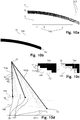
- FIGS. 10a to 10f illustrate the processing steps that the data processing unit 5 performs:
- FIG. 10a shows an illustration of unprocessed image data 14.
- image data 14 is an image of the wire 141, labels and marks 142 and image defects 143.
- Image error 143 for example, by unwanted contamination, defects in optical elements, the detector or reading the data arise.
- Labels and markers 142 may, for example, be mounted on the illumination device 9 and help to associate image data 14 with a viewing direction. Measurements of intensities, colors or lengths can also be simplified or calibrated by markings.
- an image section 15 is cut out.
- the section can preferably be chosen so that as many aberrations and artifacts are outside of the image section 15 and this nevertheless still a long piece of the wire 2 detected.
- FIG. 10b shows the result after the image section 15 has been obtained from the unprocessed image data 14 and the image data has been binarized.
- the binarization of the image data is done by having all data below or equal to a threshold receive a first value 16b and all data above the threshold associated with a second value 16a.
- FIG. 10c shows, for illustrative purposes, only a very small portion of the image data from the image section 15.
- Each pixel 17 is shown here as a box.
- the value of the individual pixel 17 is indicated by its color: white boxes have a first value 16b and black boxes have a second value 16a.
- Direct neighbors 171 of a pixel 17 are all pixels 17 which share a common page or corner with the pixel 17 in question.
- the pixels 17 here all have the same length 172.
- the length of a pixel is preferably its extension in the direction of the wire longitudinal axis of a perfectly straight wire 2 guided in the wire guide 3.
- FIG. 10d illustrates how the shell points 20 are found in known contours 18a and 18b.
- a reference point 19 far away from both contours 18a and 18b, is selected.
- the size of a test area 191 is determined, in particular its length 1911.
- the length 1911 of the test area 191 corresponds approximately to 1.75 times a regular structure of both contours 18a, 18b.
- the distance 192 or 193 to the reference point 19 is determined.
- the first contour 18a that is to say the contour 18 which is closer to the reference point 19
- the smallest distance 193a of all distances 192, 193a of pixels 17 of the contour 18a which lie within the relevant test area 191 is sought.
- the relevant pixel is a hull point 20 of the first contour 18a.
- the test area 191 is shifted by at least the length 172 of a pixel or a multiple thereof and the determination of a skin point 20 is repeated.
- the 181 is the estimated mean distance between the two contours 18a and 18b.
- the average distance between the two contours can be determined, for example, by calculating the distance between the two contours at a randomly selected but sufficiently large number of points.
- the number of pixels could also be counted, which have the second value in the binarized image section and the number divided by the, in number of pixel lengths 172 specified, length of the image section 15.
- the length of the image section 15 can in turn be determined along the longitudinal axis of an ideally straight and clamped in the wire guide 3 wire 2.
- FIG. 10e Finally, a possible result is shown when interpolating between the various envelope points.
- 18a and 18b are the original contours.
- 21a and 21b are the contour envelopes following the interpolation of the envelope points.
- FIG. 10f Three measurement windows 22 each having the same size are defined. The center of area 222 of all pixels 17 is formed, which lie both within the relevant measuring window 22 and between the contours 18a, 18b or the contour envelopes 21a, 21b. This results in a centroid 222 in each of the measurement windows 22.
- a vector 223 is determined which connects the two furthest apart centroids 222. The largest distance 23 of a centroid 222 from this vector 223 is a possible measure of the wire curvature.
- two area centroids 222 define the vector 223, so that the largest distance 23 is at the same time also the only non-trivial distance.
- the three measuring windows 22 are arranged at regular intervals 224a, 224b from each other.
- the exact execution of the wire guide is not important for the choice of the camera system.
- On lighting devices can also be dispensed with.
- the data evaluation unit can be structurally integrated into the device (for example by being inside the pedestal 8 or directly mounted thereon) or it can be a logical integration in which the data evaluation unit is arranged at a different location than the wire guide and the camera system.
- Direction element controller 12 and data evaluation unit 5 can be executed in a computer and even in their logic hardly separable connected to each other or spatially and / or logically completely separate elements.
Description
Die Erfindung betrifft eine Vorrichtung zur Erfassung einer Drahtkrümmung, welche eine Drahtführung umfasst. Ferner betrifft die Erfindung eine Drahtrichteinheit, welche eine erfindungsgemässe Vorrichtung zur Erfassung einer Drahtkrümmung umfasst. Ebenso bezieht sich die Erfindung auf ein Verfahren zur Bestimmung der Drahtkrümmung mit Hilfe einer erfindungsgemässen Vorrichtung und ein Verfahren zum Drahtrichten mit Hilfe der erfindungsgemässen Drahtrichteinheit.The invention relates to a device for detecting a wire curvature, which comprises a wire guide. Furthermore, the invention relates to a wire straightening unit, which comprises a device according to the invention for detecting a wire curvature. Likewise, the invention relates to a method for determining the wire curvature with the aid of a device according to the invention and a method for wire straightening with the aid of the wire straightening unit according to the invention.
Draht, der weiterverarbeitet oder für einen bestimmten Zweck eingesetzt werden soll, wird in der Regel auf Spulen geliefert und weist deshalb eine gewisse Krümmung auf. Diese variiert von Fall zu Fall und hängt beispielsweise auch davon ab, wie viel Draht von der Spule bereits abgewickelt wurde. Wird der Draht mit einer anderen Krümmung, insbesondere in möglichst gerader Form benötigt, so wird er vor der weiteren Verarbeitung gerichtet oder gereckt. Um dieses Verfahren zu optimieren, seinen Erfolg und/oder die Güte zu erfassen oder auch um festzustellen, ob ein Richten überhaupt notwendig ist, sind Vorrichtungen zur Erfassung der Drahtkrümmung notwendig. Dabei ermöglicht eine schnelle Messung, die in Durchmesser und Struktur unterschiedliche Drähte erfassen kann, eine flexible Nutzung einer solchen Vorrichtung.Wire that is to be further processed or used for a specific purpose is usually supplied on spools and therefore has a certain curvature. This varies from case to case and depends, for example, on how much wire has already been unwound from the bobbin. If the wire with a different curvature, in particular in the straightest possible form needed, it is directed or stretched before further processing. In order to optimize this process, to measure its success and / or quality, or to determine if straightening is necessary at all, wire curvature detection devices are necessary. In this case, a rapid measurement, which can detect different wires in diameter and structure, enables a flexible use of such a device.
Die
Fotodioden erlauben nur die Erfassung einer Lichtmenge: Die hier offenbarte Messvorrichtung verlangt also, dass Lichtquellen, Material und Empfänger derart zueinander angeordnet sind, dass aus empfangenen Lichtmengenschwankungen auf die Position des Materials geschlossen werden kann. Das wiederum impliziert, dass der Richtapperat beziehungsweise die Messvorrichtung bei jeder Materialänderung neu eingerichtet werden muss und gewellte Konturen, Lochmuster und/oder ähnliche Unregelmässigkeiten im Material die Messung erheblich stören können.Photodiodes allow only the detection of a quantity of light: The measuring device disclosed here thus requires that light sources, material and receiver are arranged relative to one another in such a way that it is possible to deduce the position of the material from received light quantity fluctuations. This in turn implies that the straightening device or the measuring device has to be newly set up with each material change and wavy contours, hole patterns and / or similar irregularities in the material can significantly interfere with the measurement.
Die
Auch die in der
Die
Eine Krümmung kann bei diesem Verfahren erst auf vielen Einzelmessungen aus vielen unterschiedlichen Richtungen gewonnen werden. Für einen langen Draht, der nicht einfach auf einen rotierbaren Tisch gelegt werden kann, ist das Verfahren daher ungeeignet.A curvature can be obtained in this method only on many individual measurements from many different directions. For a long wire that can not easily be placed on a rotatable table, the method is therefore unsuitable.
In dem Artikel von Muralikrishnan et al. "Fiber deflection probe for small hole metrology" wird vorgeschlagen eine Auslenkung einer seitlich beleuteten Faser anhand der Beobachtung ihres Schattenwurfs festzustellen. Die Faser wird dabei als zylindrische Linse genutzt.In the article by Muralikrishnan et al. "Fiber deflection test for small hole metrology" is proposed to detect a deflection of a laterally illuminated fiber by observing its shadow cast. The fiber is used as a cylindrical lens.
Ein Draht lässt sich, anders als eine optische Faser, nicht als Linse benutzen. Daher eignet sich auch dieses Verfahren nicht zur Bestimmung von Drahtkrümmung.A wire, unlike an optical fiber, can not be used as a lens. Therefore, this method is not suitable for determining wire curvature.
Die
Die Vorrichtung kann die Krümmung nur über eine fest eingestellte Messstrecke konstanter Länge bestimmen. Sollen kleinere, lokale Krümmungen erfasst werden, so muss die Messstrecke umgebaut werden.The device can determine the curvature only over a permanently set measuring path of constant length. If smaller, local curvatures are to be detected, then the test section must be rebuilt.
Aufgabe der Erfindung ist es, eine dem eingangs genannten technischen Gebiet zugehörende Vorrichtung zur Erfassung einer Drahtkrümmung zu schaffen, welche flexibel für Drähte verschiedener Dicke und/oder verschiedener Oberflächenstruktur genutzt werden kann.The object of the invention is to provide a device for detecting a wire curvature associated with the technical field mentioned above, which can be used flexibly for wires of different thickness and / or different surface structure.
Die Lösung der Aufgabe ist durch die Merkmale des Anspruchs 1 definiert. Gemäss der Erfindung umfasst eine Vorrichtung zur Erfassung einer Drahtkrümmung mit einer Drahtführung weiter
- a) ein Kamerasystem umfassend mindestens eine Kamera, wobei das Kamerasystem derart positioniert und dimensioniert ist, dass es einen in der Drahtführung geführten Draht und seine Begrenzung senkrecht zu einer Drahtlängsachse als Bilddaten erfassen kann, und
- b) eine Datenauswertungseinheit, welche die Bilddaten des Kamerasystems empfangen und daraus die Drahtkrümmung bestimmen kann.
- a) a camera system comprising at least one camera, wherein the camera system is positioned and dimensioned such that there is one in the wire guide guided wire and its boundary can detect perpendicular to a wire axis as image data, and
- b) a data evaluation unit which can receive the image data of the camera system and determine therefrom the wire curvature.
Das Kamerasystem erlaubt die optische Erfassung des geführten Drahtes. Im Gegensatz zu einfachen Lichtschranken und einzelnen Photodetektoren, erlaubt ein Kamerasystem die Erfassung von Bilddaten und stellt so kaum Anforderungen an den Draht, um dessen Geometrie überhaupt erfassen zu können: Er sollte einzig durch das Blickfeld der Kamera laufen.The camera system allows the optical detection of the guided wire. In contrast to simple light barriers and individual photodetectors, a camera system allows the acquisition of image data and thus makes little demands on the wire in order to capture its geometry at all: it should only run through the field of view of the camera.
Bilddaten, im Sinne dieser Erfindung, sind insbesondere Datenobjekte, welche mehrere, im Wesentlichen gleichzeitig empfangene Messwerte einer Lichtmenge in einem oder mehreren Wellenlängenbereichen (im folgenden als "Intensitätsdaten" bezeichnet) umfassen und dabei auch Informationen über den räumlichen Bezug der Intensitätsdaten zueinander (im Folgenden als "Lageinformation der Intensitätsdaten" bezeichnet), umfassen. Die Wellenlängenbereiche müssen nicht zwingend im sichtbaren Spektrum des Lichts liegen. Beispielsweise können auch Bereiche aus dem Infrarot oder UV-Bereich genutzt werden. Auch die Nutzung einzelner Wellenlängen von Licht ist möglich. Die Lageinformation der Intensitätsdaten kann dabei insbesondere über die Reihenfolge der Intensitätsdaten, den Speicherort, und/oder durch weitere Daten oder eine Kombination dieser Informations-Quellen gegeben sein.Image data, for the purposes of this invention, are in particular data objects which comprise a plurality of substantially simultaneously received measured values of a light quantity in one or more wavelength ranges (hereinafter referred to as "intensity data") and thereby also information about the spatial relationship of the intensity data to one another (hereinafter as "position information of the intensity data"). The wavelength ranges do not necessarily have to lie in the visible spectrum of the light. For example, areas from the infrared or UV range can also be used. The use of individual wavelengths of light is possible. The position information of the intensity data can in particular be given by the order of the intensity data, the storage location, and / or by further data or a combination of these information sources.
Die Bilddaten im Sinne der Erfindung werden insbesondere durch Pixel gebildet, welche jeweils einen Intensitätswert messen. Die Menge aller, in einer im Wesentlichen gleichen Zeitspanne, gemessenen Intensitätswerte bilden die Intensitätsdaten. Die grösste Ausdehnung eines Pixels ist dabei insbesondere grösser als der Abstand zum nächstliegenden Pixel. Bevorzugt ist die räumliche Lage der Pixel in einer Kamera zueinander fest, also zeitlich im Wesentlichen unveränderbar.The image data in the sense of the invention are formed in particular by pixels which each measure an intensity value. The amount of all the intensity values measured in a substantially equal period of time form the intensity data. The largest extent of a pixel is in particular greater than the distance to the nearest pixel. The spatial position of the pixels in a camera is preferably fixed relative to one another, that is to say essentially unalterable over time.
Bevorzugt umfasst die Kamera mehr als 100 Pixel. Bevorzugt sind die Pixel Teil eines CCD- oder eines CMOS-Detektors.Preferably, the camera comprises more than 100 pixels. Preferably, the pixels are part of a CCD or a CMOS detector.
Ein Kamerasystem kann weiter mindestens ein optisches Element wie einen Spiegel, eine Linse, eine Blende, einen Filter und/oder einen Lichtleiter umfassen und mindestens ein Ausrichtungs- und/oder Positionierungssystem, welches unverstellbar oder manuell oder durch Antriebe verstellbar sein kann. Das Ausrichtungs- und/oder Positioniersystem kann insbesondere die Positionen und/oder Ausrichtungen von optischen Elementen des Kamerasystems und/oder der Kamera zueinander festlegen. Weiter kann ein Kamerasystem eine Kamerasystemsteuerung umfassen, welche ein Ausrichtungs- und/oder Positioniersystem und insbesondere einen Antrieb steuern und/oder regeln kann, bevorzugt auch in Abhängigkeit von Messwerten und/oder durch Bilddaten, welche durch die Kamera des Kamerasystems oder eine andere Kamera oder einen anderen Detektor erfasst wurden.A camera system may further comprise at least one optical element such as a mirror, a lens, a shutter, a filter and / or a light guide, and at least one alignment and / or positioning system which may be adjustable or manually or by actuators. The alignment and / or positioning system may in particular the positions and / or orientations of optical elements of the Camera system and / or the camera to each other. Furthermore, a camera system may comprise a camera system control which can control and / or regulate an alignment and / or positioning system and in particular a drive, preferably also as a function of measured values and / or image data transmitted by the camera of the camera system or another camera or another detector was detected.
Eine Drahtführung ist im Sinne der Erfindung eine Vorrichtung, welche einen Draht an mindestens einer Stelle in einer vorgegeben Lage hält. Dabei soll es bevorzugt zulässig sein, dass sich der Draht entlang seiner Längsachse durch die Drahtführung oder Teile von ihr bewegt. Bevorzugt umfasst zumindest ein Teil der Drahtführung eine Öffnung, welche im Wesentlichen dem Aussenquerschnitt des Drahtes entspricht. Besonders bevorzugt ist diese Öffnung variabel, so dass ihre Grösse an verschiedene Aussenquerschnitte des Drahtes angepasst werden kann oder sich diesen automatisch anpasst. In einer bevorzugten Ausführungsform umfasst die Drahtführung zwei Stellen, an welchen derselbe Draht in einer vorgegebenen Lage gehalten werden kann, und das Bildfeld der Kamera umfasst insbesondere einen Abschnitt zwischen diesen beiden Stellen, so dass ein von der Drahtführung geführter Draht zwischen den beiden Stellen von der Kamera erfasst werden kann.A wire guide is in the context of the invention, a device which holds a wire at least one point in a predetermined position. In this case, it should preferably be permissible for the wire to move along its longitudinal axis through the wire guide or parts thereof. Preferably, at least part of the wire guide comprises an opening which substantially corresponds to the outer cross section of the wire. Particularly preferably, this opening is variable, so that its size can be adapted to different outer cross sections of the wire or automatically adapts to this. In a preferred embodiment, the wire guide comprises two points at which the same wire can be held in a predetermined position, and in particular the image field of the camera comprises a section between these two points, so that a guided by the wire guide wire between the two points of the Camera can be detected.
Eine Datenauswertungseinheit kann beispielsweise ein Computer mit einem Prozessor und/oder einer Graphikkarte oder eine andere Art von Rechner sein. Zumindest Teile der Datenauswertung können aber auch manuell durchgeführt werden, so dass eine Datenauswertungseinheit Darstellungsmittel, Auswahl- bzw. Eingabemittel und einen Benutzer umfassen kann.A data evaluation unit can be, for example, a computer with a processor and / or a graphics card or another type of computer. However, at least parts of the data evaluation can also be carried out manually, so that a data evaluation unit can comprise presentation means, selection or input means and a user.
Das Bildfeld einer Kamera ist bevorzugt der Raumwinkelbereich, aus welchem Licht mindestens einen Pixel oder einen Teil des Detektors der Kamera erreichen kann, und dieser Pixel einen Teil der Bilddaten liefert. Insbesondere soll das Bildfeld einer Kamera vollständig ausserhalb der Kamera und insbesondere ausserhalb des Kamerasystems liegen. Dabei soll "ausserhalb der Kamera/ des Kamerasystems" bedeuten, dass in dem Strahlengang, in Richtung vom Pixel weg, kein weiteres optisches Element der Kamera oder des Kamerasystems passiert wird.The image field of a camera is preferably the solid angle range, from which light at least one pixel or a part of the detector of the camera can reach, and this pixel supplies a part of the image data. In particular, the image field of a camera should be completely outside the camera and in particular outside the camera system. In this case, "outside the camera / of the camera system" means that no further optical element of the camera or the camera system is passed in the beam path, away from the pixel.
Die Blickrichtung einer Kamera ist bevorzugt die mittlere Richtung des Bildfeldes, also insbesondere diejenige Richtung die durch die Flächenschwerpunkte der Flächen, erreichbar durch Strahlen gleicher Länge ausgehend von den Pixeln der Kamera, gebildet wird. Bevorzugt ist die Blickrichtung gleich der Verlängerung der optischen Achse des letzten optischen Elements von Kamera oder Kamerasystem, in Richtung weg von den Pixeln der Kamera.The viewing direction of a camera is preferably the middle direction of the image field, ie in particular that direction which is formed by the centroids of the surfaces, achievable by rays of the same length starting from the pixels of the camera. The viewing direction is preferably the same as the extension of the optical axis of the last optical element of the camera or camera system, in the direction away from the pixels of the camera.
In einer Ausführungsform umfasst das Kamerasystem mindestens zwei Kameras mit jeweils einer Blickrichtung. Beide Kameras sind derart positioniert und dimensioniert, dass sie einen in der Drahtführung geführten Draht und seine Begrenzung senkrecht zur Drahtlängsachse als Bilddaten erfassen können. Die Blickrichtungen der mindestens zwei Kameras stehen in einem Winkel von grösser 0°, bevorzugt in einem Winkel zwischen 45° und 90°, insbesondere bevorzugt in einem Winkel von 90°, zueinander.In one embodiment, the camera system comprises at least two cameras, each with a viewing direction. Both cameras are positioned and dimensioned such that they can detect a guided in the wire guide wire and its boundary perpendicular to the wire axis as image data. The viewing directions of the at least two cameras are at an angle of greater than 0 °, preferably at an angle between 45 ° and 90 °, particularly preferably at an angle of 90 ° to each other.
Durch die Nutzung von Bilddaten zweier Kameras, deren Blickrichtungen in einem Winkel von grösser 0° zueinander stehen, können die Begrenzungen des Drahtes in zwei unterschiedlichen und linear unabhängigen Ebenen erfasst werden. Daher erlaubt eine solche Anordnung die Erfassung der Drahtkrümmung in drei Raumdimensionen.By using image data from two cameras whose viewing angles are at an angle greater than 0 ° to each other, the boundaries of the wire can be detected in two different and linearly independent planes. Therefore, such an arrangement allows the detection of wire curvature in three spatial dimensions.
Bei der Bestimmung des Winkels, in welchem die Blickrichtungen zueinander stehen, sollen die Blickrichtungen als Gerade angesehen werden und jeweils der spitze Winkel bestimmt werden. Nach dieser Definition können die Blickrichtungen also nur in Winkeln zwischen 0° und 90° zueinander stehen.When determining the angle in which the viewing directions are to each other, the viewing directions should be considered as a straight line and each of the acute angle to be determined. According to this definition, the viewing directions can therefore only be in angles between 0 ° and 90 ° to each other.
Bevorzugt haben die Blickrichtungen zwar eine definierte Richtung, aber keine definierte Lage und können daher, zwecks Bestimmung des eingeschlossenen Winkels mathematisch im Raum verschoben werden, bis ein Schnittpunkt entsteht. Insbesondere können die Blickrichtungen entlang oder parallel zur Längsachse des Drahtes und/oder zur Fortsetzung der Längsachse eines Drahtes, welcher in der Drahtführung geführt wird, verschoben werden, um einen Schnittpunkt zu erreichen, an welchem der eingeschlossene Winkel bestimmt werden kann.Although the viewing directions preferably have a defined direction, they do not have a defined position and can therefore be mathematically shifted in space for the purpose of determining the included angle, until an intersection point arises. In particular, the directions of view along or parallel to the longitudinal axis of the wire and / or to continue the longitudinal axis of a wire, which is guided in the wire guide can be moved to achieve an intersection at which the included angle can be determined.
Je grösser der eingeschlossene Winkel ist, desto grösser ist der Winkel zwischen den Beobachtungsebenen. Die Zuordnung einer erfassten Krümmung in senkrecht zueinander stehenden Ebenen, wie in kartesischen Koordinaten üblich, wird bei grösseren Winkeln einfacher und weniger anfällig für Messfehler. Dieser Effekt zeigt sich deutlich bei Winkeln von 45° bis 90°. Bei dem maximalen Winkel von 90° ist die Auswertung am einfachsten und am wenigsten fehleranfällig.The larger the included angle, the greater the angle between the observation planes. The assignment of a detected curvature in perpendicular to each other Standing planes, as is common in Cartesian coordinates, become easier and less prone to measurement errors at larger angles. This effect is evident at angles of 45 ° to 90 °. At the maximum angle of 90 °, the evaluation is easiest and least error-prone.
In einer Ausführungsform schliessen die Blickwinkel von zwei oder mehr Kameras eines Kamerasystems einen Winkel von im Wesentlichen 0° untereinander ein. Dies erlaubt die Erfassung einer Drahtkrümmung in einer Ebene durch zwei unabhängige Messungen. So können Messfehler reduziert werden, und zudem weisst ein solches Kamerasystem eine gewisse Redundanz auf und daher eine höhere Zuverlässigkeit.In one embodiment, the viewing angles of two or more cameras of a camera system enclose an angle of substantially 0 ° with each other. This allows the detection of a wire curvature in a plane by two independent measurements. Thus, measurement errors can be reduced, and in addition, such a camera system has a certain redundancy and therefore a higher reliability.
In einer weiteren Ausführungsform umfasst das Kamerasystem eine Kamera und eine Schwenkeinheit. Die Schwenkeinheit umfasst einen Schwenkarm und einen Grundteil. Die Kamera ist an dem Schwenkarm befestigt. Der Schwenkarm ist relativ zum Grundteil verschwenkbar. Die Kamera kann durch ein Verschwenken des Schwenkarms eine erste und eine zweite Position erreichen. In der ersten und der zweiten Position kann die Kamera einen in der Drahtführung geführten Draht und seine Begrenzungen senkrecht zur Drahtlängsachse als Bilddaten erfassen. Die Kamera hat in der ersten und zweiten Position jeweils eine unterschiedliche Blickrichtung. Die Blickrichtung der Kamera in der ersten und einer zweiten Position schliesst einen Winkel von grösser 0°, bevorzugt einen Winkel zwischen 45° und 90°, insbesondere bevorzugt einen Winkel von 90°, ein.In a further embodiment, the camera system comprises a camera and a pivoting unit. The pivot unit comprises a pivot arm and a base. The camera is attached to the swivel arm. The swivel arm is pivotable relative to the base part. The camera can achieve a first and a second position by pivoting the pivot arm. In the first and second positions, the camera can detect a wire guided in the wire guide and its boundaries perpendicular to the wire longitudinal axis as image data. The camera has a different viewing direction in the first and second position. The viewing direction of the camera in the first and a second position includes an angle greater than 0 °, preferably an angle between 45 ° and 90 °, particularly preferably an angle of 90 °.
Eine Schwenkeinheit erlaubt es, eine Kamera derart zu bewegen, dass sie in zwei Blickrichtungen einen in der Drahtführung geführten Draht erfassen kann. Anstelle oder zusätzlich zu einer Schwenkeinheit können auch Antriebe und Verstelleinheiten genutzt werden, die in linearer Richtung wirken, und/oder es kann mehrere Beobachtungspunkte geben, in welche eine Kamera gesetzt oder an welchen sie befestigt werden kann, und/oder die Kamera selbst kann ortsfest montiert sein, aber eine optische Einheit wie z.B. ein Umlenkspiegel verändert bei einem Umschalten die Blickrichtung der Kamera. Eine umschaltbare Optik und feste Beobachtungspunkte haben den Vorteil, dass der Winkel zwischen den Blickrichtungen durch die Konstruktion gegeben ist und daher keine Winkelmessung bei der Drahtkrümmungsmessung nötig ist.A swivel unit allows a camera to be moved in such a way that it can detect a wire guided in the wire guide in two viewing directions. Instead of or in addition to a pivoting unit, it is also possible to use drives and adjusting units which act in a linear direction, and / or there can be several observation points into which a camera can be set or to which it can be attached, and / or the camera itself can be stationary mounted, but an optical unit such as a deflecting mirror changes the viewing direction of the camera when switching. Switchable optics and fixed observation points have the advantage that the angle between the viewing directions is given by the construction and therefore no angle measurement is necessary in the wire bend measurement.
Ähnlich wie in der Ausführungsform mit zwei Kameras, erlaubt es eine dieser Vorrichtungen oder eine Kombination von ihnen, insbesondere die Schwenkeinheit mit der daran befestigen Kamera, Bilddaten in zwei unterschiedlichen Beobachtungsebenen zu gewinnen und so die Krümmung eines Drahtes in drei Raumdimensionen zu erfassen.Similar to the embodiment with two cameras, one of these devices or a combination of them, in particular the pivoting unit with the camera attached thereto, allows to acquire image data in two different observation planes and thus to detect the curvature of a wire in three spatial dimensions.
In einer Ausführungsform umfasst die Schwenkeinheit einen Antrieb, mittels welchem der Schwenkarm relativ zum Grundteil verschwenkbar ist.In one embodiment, the pivoting unit comprises a drive, by means of which the pivoting arm is pivotable relative to the base part.
Eine Schwenkeinheit, umfassend einen Grundkörper, einen Schwenkarm und eine an diesem Schwenkarm fest montierte Kamera, ermöglicht eine vergleichsweise einfache und präzise Bewegung und Positionierung der Kamera. Insbesondere kann der Winkel, den die Blickrichtungen einschliessen, in einem weiten Bereich durch eine Steuerung des Antriebs eingestellt werden.A pivoting unit comprising a base body, a pivoting arm and a fixedly mounted on this pivoting camera, allows a comparatively simple and precise movement and positioning of the camera. In particular, the angle, which include the viewing directions, can be adjusted in a wide range by controlling the drive.
In dem Antrieb integriert oder an dem Antrieb angeschlossen ist insbesondere auch eine Winkelmessvorrichtung, welche den Winkel zwischen der Kamerablickrichtung in der ersten und in der zweiten Position erfassen kann. So kann der Antrieb zum Beispiel durch einen Schrittmotor realisiert sein, der Daten zu seiner Position und/oder Positionsänderung liefert, oder es kann ein Sensor und eine Scheibe mit Markierungen verwendet werden, um die aktuelle Position des Schwenkarms relativ zum Grundkörper zu erfassen.Integrated in the drive or connected to the drive is in particular also an angle measuring device, which can detect the angle between the camera viewing direction in the first and in the second position. For example, the drive may be implemented by a stepper motor that provides data on its position and / or position change, or a sensor and a disc with markers may be used to detect the current position of the pivot arm relative to the body.
Bei dem Antrieb handelt es sich insbesondere um einen Elektromotor.The drive is in particular an electric motor.
Anstelle eines Antriebs oder zusätzlich zu diesem, kann die Schwenkeinheit auch eine Reihe von Raststufen oder Anschlägen umfassen, in welche der Schwenkarm durch einen äusseren Impuls, durch Herunterfallen durch sein Eigengewicht oder durch Erwärmung, Abkühlung oder Verformung eines Abstandshalters gelangt. Ist der Winkelabstand zwischen den Raststufen oder Anschlägen bekannt, so kann auf eine Messung des Winkels der Blickrichtungen verzichtet werden.Instead of a drive or in addition to this, the pivot unit may also comprise a series of detent steps or stops, in which the pivot arm passes through an external impulse, by falling by its own weight or by heating, cooling or deformation of a spacer. If the angular distance between the latching steps or stops known, it can be dispensed with a measurement of the angle of view.
In einer Ausführungsform ist eine Achse, um welche der Schwenkarm relativ zum Grundteil verschwenkbar ist, im Wesentlichen gleich der Achse, welche der Längsachse eines in der Drahtführung geführten Drahtes, insbesondere im Bereich der Drahtführung, entspricht.In one embodiment, an axis about which the pivot arm is pivotable relative to the base part, substantially equal to the axis which corresponds to the longitudinal axis of a guided in the wire guide wire, in particular in the region of the wire guide.
Das Grundteil ist insbesondere fest gegenüber der Drahtführung positioniert.The base is in particular firmly positioned opposite the wire guide.
Wenn die Achse, um welche der Schwenkarm verschwenkbar ist, im Wesentlichen der Längsachse eines in der Drahtführung geführten Drahtes entspricht, und die Kamera an dem Schwenkarm befestigt ist, so bleibt der Abstand zwischen der Längsachse des zu beobachtenden Drahtes und der Kamera im Wesentlichen konstant. Damit kann sich die Messung vereinfachen, da typische Grössen, wie z.B. die Ausdehnung des Drahtes senkrecht zu seiner Längsachse, in allen Kamerapositionen gleich oder ähnlich sind und sich auch der Fokus der Kamera, wenn überhaupt, nur wenig verschiebt. Die Bildauswertung vereinfacht sich daher.When the axis about which the pivot arm is pivotable substantially corresponds to the longitudinal axis of a wire guided in the wire guide, and the camera is mounted on the pivot arm, the distance between the longitudinal axis of the wire to be observed and the camera remains substantially constant. Thus, the measurement can be simplified since typical quantities, e.g. the extension of the wire perpendicular to its longitudinal axis, are the same or similar in all camera positions and the focus of the camera, if at all, shifts only slightly. The image evaluation is therefore simplified.
Wenn die Achse, um welche der Schwenkarm verschwenkbar ist, gegenüber der Längsachse eines in der Drahtführung geführten Drahtes parallel verschoben ist, ändert sich der Abstand zwischen beobachtetem Draht und Kamera. Dies erlaubt, den Draht in unterschiedlichen Auflösungen zu erfassen.If the axis about which the pivoting arm is pivotable is displaced parallel to the longitudinal axis of a wire guided in the wire guide, the distance between observed wire and camera changes. This allows to capture the wire in different resolutions.
Wenn die Achse, um welche der Schwenkarm verschwenkbar ist, gegenüber der Längsachse eines in der Drahtführung geführten Drahtes verkippt ist, lassen sich weitere Blickrichtungen erfassen.If the axis about which the pivoting arm is pivotable is tilted with respect to the longitudinal axis of a wire guided in the wire guide, further viewing directions can be detected.
In einer Ausführungsform umfasst die Vorrichtung zur Erfassung einer Drahtkrümmung eine Beleuchtungseinrichtung. Die Beleuchtungseinrichtung ist insbesondere so angeordnet, dass sie Licht in einer umgekehrten Blickrichtung einer Kamera des Kamerasystems aussenden kann.In one embodiment, the device for detecting a wire curvature comprises a lighting device. The illumination device is in particular arranged so that it can emit light in a reverse viewing direction of a camera of the camera system.
Ist die Umgebung, in welcher die Vorrichtung betrieben wird, hell genug bzw. die Kamera der Vorrichtung lichtempfindlich genug, so können auch ohne Beleuchtungseinrichtung von der Kamera Bilddaten gewonnen werden, welche sich zur Auswertung durch die Datenauswertungseinheit eignen.If the environment in which the device is operated is sufficiently bright or the camera of the device is light-sensitive enough, image data can also be obtained from the camera without illumination device which are suitable for evaluation by the data evaluation unit.
Umfasst die Vorrichtung selbst eine Beleuchtungseinrichtung, so kann die Beleuchtung auf optimale Betriebsbedingungen der Kamera und/oder auf eine besonders einfache und klare Datenauswertung in der Datenauswertungseinheit hin optimiert werden.If the device itself comprises a lighting device, then the lighting can be optimized for optimum operating conditions of the camera and / or for a particularly simple and clear data evaluation in the data evaluation unit.
Die Beleuchtungseinrichtung kann so angeordnet sein, dass viel von dem Licht am Draht reflektiert und gestreut wird und dieses Licht von den Pixeln der Kamera erfasst wird. Eine solche Beleuchtung erlaubt es, Details von der der Kamera zugewandten Seite des Drahtes als Bilddaten zu erfassen.The illumination device may be arranged so that much of the light is reflected and scattered on the wire and that light is detected by the pixels of the camera. Such illumination allows details of the camera-facing side of the wire to be captured as image data.
Die Beleuchtungseinheit kann aber auch so angeordnet sein, dass Licht der Beleuchtungseinheit auf dem Weg zu den Pixeln der Kamera abgedeckt wird und von der Kamera weggestreut bzw. wegreflektiert wird. Die Beleuchtungseinrichtung ist dann so angeordnet, dass sie Licht in einer umgekehrten Blickrichtung einer Kamera aussendet. Der Draht erscheint in diesem "Backlight" dann als im Wesentlichen gleichmässig dunkel, vor einem hellen Hintergrund. Um die Konturen des Drahtes zu erfassen, hat dies den Vorteil, dass die Bilddaten nicht mehr Details zeigen als von Interesse für die Erfassung der Drahtkrümmung sind. Die Auswertung ist daher weniger fehleranfällig.The lighting unit can also be arranged so that light of the lighting unit is covered on the way to the pixels of the camera and is scattered away or reflected away from the camera. The illumination device is then arranged to emit light in a reversed viewing direction of a camera. The wire then appears in this "backlight" as substantially uniformly dark, against a light background. To capture the contours of the wire, this has the advantage that the image data does not show more details than are of interest for detecting the wire curvature. The evaluation is therefore less error-prone.
In einer bevorzugten Ausführungsform ist die Beleuchtungseinrichtung derart ausgebildet, dass sie im Wesentlichen über das gesamte eine gesamte, von der Kamera erfasste Fläche, gleichmässig Licht abstrahlt.In a preferred embodiment, the illumination device is designed such that it emits light substantially uniformly over the entire entire area covered by the camera.
Ein besonders vorteilhafter und klarer Kontrast zwischen Draht und Hintergrund lässt sich auf den Bilddaten erreichen, wenn der darauf abgebildete Hintergrund gleichmässig ausgeleuchtet ist. Insbesondere ist daher die Beleuchtung im Bereich des Kamerablickfeldes im Wesentlichen gleichmässig. Bevorzugt ist eine im Wesentlichen gleichmässige Beleuchtung, die weniger als 30% in der Intensität im von der Kamera erfassten Bereich schwankt, insbesondere um weniger als 10%.A particularly advantageous and clear contrast between the wire and the background can be achieved on the image data if the background depicted on it is uniformly illuminated. In particular, therefore, the illumination in the field of camera field of view is substantially uniform. A substantially uniform illumination that fluctuates less than 30% in the intensity in the area covered by the camera is preferred, in particular by less than 10%.
Die Beleuchtungseinheit kann zum Beispiel als von hinten oder der Seite beleuchteten Box mit einer diffusen Oberfläche, wie z.B. Milchglas oder geeignetem Paper, oder mehreren hintereinander angeordneten diffusen Oberflächen gestaltet sein. Beleuchtungseinheiten, die eine im Wesentlichen gleichmässige Beleuchtung erzeugen, sind zum Beispiel zur Kalibration von Teleskopen oder als Zubehör für professionelle Fotographen erhältlich. Leuchtmittel können beispielsweise LEDs, Leuchtstoffröhren, Glühlampen, Gasentladungsröhren oder andere Leuchtmittel umfassen. Das erzeugte Licht kann auf einzelne Wellenlängen konzentriert sein oder aber ein möglichst gleichmässiges Spektrum aufweisen und ist insbesondere auf die Empfindlichkeit der Pixel der Kamera abgestimmt.The lighting unit can be designed, for example, as a back-lit or side-lit box having a diffuse surface, such as frosted glass or a suitable paper, or a plurality of diffused surfaces arranged one behind the other. Lighting units that produce substantially uniform illumination are available, for example, for telescopic calibration or as an accessory for professional photographers. Illuminants may include, for example, LEDs, fluorescent tubes, incandescent lamps, gas discharge tubes or other lamps. The generated light may be concentrated to individual wavelengths or may have as uniform a spectrum as possible and is particularly tuned to the sensitivity of the pixels of the camera.
Es ist aber auch möglich, dass eine lokale, also ungleichmässige, Lichtquelle als Backlight genutzt wird. Eine lokale Lichtquelle kann insbesondere eine oder mehrere LED's, Leuchtstoffröhren, Glühlampen, Gasentladungsröhren oder andere Leuchtmittel umfassen. Das erzeugte Licht kann auf einzelne Wellenlängen konzentriert sein oder aber ein möglichst gleichmässiges Spektrum aufweisen und ist insbesondere auf die Empfindlichkeit der Pixel der Kamera abgestimmt.But it is also possible that a local, so uneven, light source is used as a backlight. A local light source may in particular comprise one or more LEDs, fluorescent tubes, incandescent lamps, gas discharge tubes or other lighting means. The generated light may be concentrated to individual wavelengths or may have as uniform a spectrum as possible and is particularly tuned to the sensitivity of the pixels of the camera.
In einer weiteren Ausführungsform ist nur der Bereich um die erwartete Position mindestens eines Längenabschnitts eines im Wesentlichen gleichmässig beleuchtet durch die Beleuchtungseinheit. Dabei erstreckt sich der Bereich in Richtung senkrecht zur erwarteten Lage der Drahtlängsachse, bevorzugt um mindestens 0.25 der zu erwartenden Drahtdicke auf beiden Seiten dieser zu erwartenden Drahtdicke, also 0.75 der zu erwartenden Drahtdicke ausgehend von der Drahtlängsachse. Der Längenabschnitt des Drahtes erstreckt sich insbesondere über mindestens 5 zu erwartende Drahtdicken in Richtung der zu erwartenden Längsachse des Drahtes.In a further embodiment, only the area around the expected position of at least one longitudinal section of a substantially uniformly illuminated by the illumination unit. In this case, the region extends in the direction perpendicular to the expected position of the wire longitudinal axis, preferably by at least 0.25 of the expected wire thickness on both sides of this expected wire thickness, ie 0.75 of the expected wire thickness starting from the wire longitudinal axis. The length section of the wire extends in particular over at least 5 expected wire thicknesses in the direction of the expected longitudinal axis of the wire.
In einer Ausführungsform ist jede Kamera des Kamerasystems einer Beleuchtungseinrichtung zugeordnet, welche Licht in einer umgekehrten Blickrichtung der jeweiligen Kamera aussenden kann.In one embodiment, each camera of the camera system is associated with a lighting device which can emit light in a reversed viewing direction of the respective camera.
Bevorzugt erfüllt jede dieser Beleuchtungseinrichtungen wenigstens eine der oben beschriebenen möglichen Eigenschaften von Beleuchtungseinrichtungen.Each of these lighting devices preferably fulfills at least one of the possible properties of lighting devices described above.
Ist jeder Kamera des Kamerasystems eine ähnlich gestaltete Beleuchtungseinrichtung zugeordnet und handelt es sich um vergleichbar lichtempfindliche Kameras mit ähnlicher Auflösung, so können sich die Bilddaten der verschiedenen Kameras im Wesentlichen nur durch den Blickwinkel, aber nicht durch andere Eigenschaften, unterscheiden. Dies vereinfacht die Auswertung und die Vergleichbarkeit der erfassten Bilddaten.If each camera of the camera system is assigned a similarly designed illumination device and if the cameras are of comparable resolution with similar resolution, then the image data of the various cameras can essentially only be distinguished by the viewing angle, but not by other properties. This simplifies the evaluation and the comparability of the acquired image data.
In einer Ausführungsform wird eine einzige Beleuchtungseinrichtung von mehreren Kameras genutzt. Die Beleuchtungseinrichtung kann so gross sein, dass sie im Blickfeld mehrerer Kameras liegt. Eine Beleuchtungseinrichtung kann aber auch so bewegt werden, dass sie zur Erfassung erster Bilddaten von einer ersten Kamera genutzt wird und zur Erfassung zweiter Bilddaten von einer zweiten Kamera mit einer anderen Blickrichtung.In one embodiment, a single illumination device is used by multiple cameras. The illumination device can be so large that it lies in the field of view of several cameras. However, a lighting device can also be moved in such a way that it is used to acquire first image data from a first camera and to acquire second image data from a second camera with a different viewing direction.
In einer Ausführungsform ist eine Beleuchtungseinrichtung an dem Schwenkarm befestigt und zwar insbesondere derart, dass sie Licht in einer umgekehrten Blickrichtung der am Schwenkarm befestigten Kamera aussenden kann.In one embodiment, a lighting device is attached to the pivot arm and in particular such that it can emit light in a reverse viewing direction of the attached to the swivel arm camera.
Diese Anordnung erlaubt eine klare und feste Zuordnung einer Kamera zu einer Beleuchtungseinheit und erlaubt trotz der Bewegung von beiden Teilen stets eine gleichbleibende Ausrichtung von Kamera und Beleuchtungseinheit aufeinander.This arrangement allows a clear and fixed assignment of a camera to a lighting unit and despite the movement of both parts always allows a consistent alignment of camera and lighting unit to each other.
In einer Ausführungsform ist eine Kamera an einem Schwenkarm einer grossflächigen Beleuchtungseinrichtung zugeordnet, welche in einer ersten und einer zweiten Kameraposition als Beleuchtungseinrichtung dient. In einer weiteren Ausführungsform sind mehrere Beleuchtungseinrichtungen an verschiedenen, geeigneten Orten und/oder mit geeigneten Ausrichtungen platziert, um Licht in die umgekehrte Blickrichtung der Kamera oder des Kamerasystems zu senden.In one embodiment, a camera is assigned to a swivel arm of a large-area lighting device, which serves as a lighting device in a first and a second camera position. In a further embodiment, a plurality of illumination devices are placed at various suitable locations and / or with appropriate orientations to transmit light in the reverse direction of the camera or camera system.
In einer Ausführungsform umfasst die Vorrichtung zur Erfassung der Drahtkrümmung weiter eine Schutzvorrichtung für die mindestens eine Kamera des Kamerasystems und insbesondere für die Beleuchtungseinrichtung. Die Schutzvorrichtung ist insbesondere derart gestaltet, dass die mindestens eine Kamera und Beleuchtungseinrichtung in einer Parkposition vor Verschmutzung durch herumfliegende Teilchen geschützt sind. Die Schutzvorrichtung umfasst insbesondere Blenden oder einseitig oder zweiseitig offene Boxen. In der Parkposition kann die mindestens eine Kamera des Kamerasystems bevorzugt keine Bilddaten eines in der Drahtführung geführten Drahtes und seiner Begrenzungen erfassen.In one embodiment, the device for detecting the wire curvature further comprises a protective device for the at least one camera of the camera system and in particular for the illumination device. The protective device is in particular designed such that the at least one camera and lighting device are protected in a parking position from contamination by flying particles. The protective device comprises in particular panels or unilaterally or two-sided open boxes. In the parking position, the at least one camera of the camera system preferably can not detect image data of a wire guided in the wire guide and its boundaries.
Das Kamerasystem und die Beleuchtungseinheit können durch herumfliegende Teile, Staub, Öl und andere Fremdkörper leicht verschmutzt und/oder beschädigt werden. Dies erschwert oder verunmöglicht die Erfassung der Drahtkrümmung.The camera system and lighting unit may be easily contaminated and / or damaged by flying objects, dust, oil, and other foreign objects. This makes it difficult or impossible to detect the wire curvature.
Um dies zu verhindern, werden die empfindlichen Teile der Vorrichtung bevorzugt geschützt. Sowohl die Kamera als auch die Beleuchtungseinheit sind besonders an ihren lichtaufnehmenden bzw. lichtabgebenden Oberflächen empfindlich. Daher werden in einer Ausführungsform diese Flächen gezielt abgedeckt, wenn Verschmutzungen zu erwarten sind.To prevent this, the sensitive parts of the device are preferably protected. Both the camera and the illumination unit are particularly sensitive to their light-receiving or light-emitting surfaces. Therefore, in one embodiment, these surfaces are specifically covered when soiling is to be expected.
Eine solche Schutzabdeckung kann durch eine einfache Blende geschehen, welche lichtdurchlässig oder lichtundurchlässig gestaltet werden kann. Wird sie lichtdurchlässig gestaltet, können trotz Nutzung der Blende noch Bilddaten gewonnen werden.Such a protective cover can be done by a simple aperture, which can be made translucent or opaque. If it is translucent, still image data can be obtained despite the use of the aperture.
Weniger Wartungsaufwand fordern lichtundurchlässige Blenden oder lichtdurchlässige Blenden, durch welche keine Bilddaten gewonnen werden.Less maintenance calls for opaque apertures or translucent apertures through which no image data is obtained.
Für einen verbesserten Schutz vor Verschmutzung können Boxen aus stabilem Material montiert werden, in welche die Kamera und/oder die Beleuchtungseinheit gelegt oder gefahren werden können.For improved protection against contamination, boxes made of sturdy material can be mounted in which the camera and / or the lighting unit can be placed or driven.
Insbesondere wenn die Kamera und gegebenenfalls die Beleuchtungseinheit an einem Schwenkarm befestigt sind, kann der Schwenkarm in eine Parkposition gefahren werden, in welcher Kamera und/oder Beleuchtungseinheit von jeweils einer Blende oder teilweise geöffneten Box abgedeckt oder umfasst werden. Auch kann es sich um eine schliessbare Box handeln. Eine schliessbare Box ist dabei bevorzugt ein Behälter, welcher entweder durch ein passendes Deckenstück an der Kamera oder Beleuchtungseinheit verschlossen werden kann oder über einen Deckelmechanismus verfügt, der die Box, zumindest wenn sie gefüllt ist, verschliesst. Bevorzugt umfasst die Schutzvorrichtung weiter einen Reinigungsmechanismus. Der Reinigungsmechanismus erlaubt zum Beispiel ein Wegblasen von aufliegenden Verschmutzungen mit Druckluft und/oder ein Auftragen von einem Reinigungsmittel und/oder ein Aufbringen oder Abtragen eines Schutzfilmes.In particular, when the camera and optionally the illumination unit are attached to a pivoting arm, the pivoting arm can be moved to a parking position, in which camera and / or lighting unit are covered or covered by a respective aperture or partially open box. It can also be a lockable box. A lockable box is preferably a container which can be closed either by a matching blanket on the camera or lighting unit or has a lid mechanism that closes the box, at least when it is filled. Preferably, the protective device further comprises a cleaning mechanism. The cleaning mechanism allows, for example, a blowing away of overlying contaminants with compressed air and / or application of a cleaning agent and / or application or removal of a protective film.
In einer Ausführungsform umfasst die Datenauswertungseinheit mindestens eine Schnittstelle, an welche mindestens eine Benutzerschnittstelle angeschlossen werden kann. Bei der Benutzerschnittstelle handelt es sich insbesondere um einen Bildschirm, eine Tastatur und/oder eine Computermaus. Auf diese Art ist ein Datenauswertungsprogramm, welches durch die Datenauswertungseinheit ausführbar ist, über eine graphische Benutzeroberfläche kalibrierbar und personalisierbar.In one embodiment, the data evaluation unit comprises at least one interface to which at least one user interface can be connected. The user interface is in particular a screen, a keyboard and / or a computer mouse. In this way, a data evaluation program, which can be executed by the data evaluation unit, can be calibrated and personalized via a graphical user interface.
Es ist auch möglich, dass die Datenauswertungseinheit vom Hersteller bereits voll kalibriert geliefert wird und daher keine Benutzerschnittstellen zu diesem Zweck mehr aufweisen muss.It is also possible that the data evaluation unit is already supplied fully calibrated by the manufacturer and therefore no longer needs user interfaces for this purpose.
In einer Ausführungsform handelt es sich bei den Benutzerschnittstellen um Drehknöpfe oder Tasten oder einen Touchscreen, welche in der Datenauswertungseinheit selbst integriert sind.In one embodiment, the user interfaces are knobs or buttons or a touch screen, which are integrated in the data evaluation unit itself.
Bei der Schnittstelle kann es sich um einen mechanischen Stecker handeln oder auch um eine drahtlose Datenverbindung.The interface may be a mechanical connector or a wireless data connection.
In einer Ausführungsform umfasst die Vorrichtung zur Erfassung einer Drahtkrümmung eine Ethernet-Verbindung, welche eine Übertragung von Bilddaten des Kamerasystems, insbesondere der mindestens einen Kamera, an die Datenauswertungseinheit ermöglicht. Eine Ethernet-Verbindung ist eine stabile und schnelle Verbindung zur Datenübertragung. Es können aber auch andere Datenübertragungsmethoden und Mittel genutzt werden, um die Bilddaten des Kamerasystems an die Datenauswertungseinheit zu übertragen. Insbesondere sind drahtlose Verfahren und die Nutzung von Lichtleitern möglich.In one embodiment, the device for detecting a wire curvature comprises an Ethernet connection, which enables transmission of image data of the camera system, in particular of the at least one camera, to the data evaluation unit. An Ethernet connection is a stable and fast connection for data transmission. However, other data transmission methods and means can also be used to transmit the image data of the camera system to the data evaluation unit. In particular, wireless methods and the use of optical fibers are possible.
In jeder Ausführungsform ist die Datenauswertungseinheit derart gestaltet, dass sie folgende Schritte ausführen kann:
- a) bevorzugt die Bilddaten auf einen gewünschten, vordefinierten Abschnitt zuschneiden, so dass ein Bildausschnitt resultiert;
- b) die Bilddaten oder den Bildausschnitt binärisieren, indem alle Bildpunkte mit einer Helligkeit geringer oder gleich als ein Schwellenwert einen ersten Wert zugewiesen erhalten und alle Bildpunkte mit einer Helligkeit grösser als der Schwellenwert einen anderen, zweiten Wert zugewiesen erhalten;
- c) aus dem binärisierten Bildausschnitt die Konturen, insbesondere eine erste und eine zweite Kontur, ermitteln, insbesondere indem alle Bildpunkte eines Wertes bestimmt werden, bei denen mindestens einer der direkten Nachbarn einen anderen Wert aufweist als der Bildpunkt selbst.
- a) preferably to crop the image data to a desired, predefined section so that a picture detail results;
- b) binarizing the image data or image by obtaining a first value assigned to all pixels having a brightness less than or equal to a threshold, and all pixels having a brightness greater than the threshold being assigned a different, second value;
- c) determine the contours, in particular a first and a second contour, from the binarized image detail, in particular by determining all pixels of a value in which at least one of the direct neighbors has a different value than the pixel itself.
Schritt a) ermöglicht es, nur diejenigen Bilddaten weiterzuverarbeiten, welche für die Drahtkrümmung von Interesse sind. Durch das Zuschneiden der Bilder kann die Vorrichtung Kameras nutzen, deren Blickfeld grösser ist als für die aktuelle Messung nötig, ohne dass überflüssige Ressourcen für die Auswertung gebraucht werden. Auf Schritt a) zu verzichten und direkt mit Bilddaten anstelle des Bildausschnitts zu arbeiten, kann die Auswertung vereinfachen, da kein Abschnitt vordefiniert werden muss.Step a) makes it possible to process only those image data which are of interest for the wire curvature. By cropping the images, the device can use cameras whose field of view is larger than necessary for the current measurement, without using unnecessary resources for the evaluation. Go to step a) dispense with and work directly with image data instead of the image section, can simplify the evaluation, since no section must be predefined.
Durch den Schritt b) wird die Grösse der Bilddaten verringert und unerwünschte Strukturen und Artefakte können zum Verschwinden gebracht werden. Gemäß der Erfindung wird Schritt b) in Schritt c) integriert, indem alle Bildpunkte bestimmt werden, die selbst einen Wert oberhalb der Schwelle und mindestens einen Nachbarn mit einem Wert unterhalb oder gleich der Schwelle haben und/oder die selbst einen Wert unterhalb oder gleich der Schwelle und mindestens einen Nachbarn mit einem Wert oberhalb der Schwelle haben. Dies spart etwas Speicherplatz und/oder Zeit zum Schreiben der Daten aus Schritt b).The step b) reduces the size of the image data and unwanted structures and artifacts can be made to disappear. According to the invention, step b) is integrated in step c) by determining all pixels which themselves have a value above the threshold and at least one neighbor with a value below or equal to the threshold and / or which themselves have a value below or equal to Threshold and have at least one neighbor with a value above the threshold. This saves some storage space and / or time to write the data from step b).
Schritt c) ermittelt alle Bildpunkte, die zur ersten oder zweiten Kontur gehören: Zur ersten oder zweiten Kontur gehören in einer Ausführungsform alle Bildpunkte mit dem ersten Wert, bei denen mindestens einer der direkten Nachbarn den zweiten Wert hat. In einer Ausführungsform gehören zur ersten oder zweiten Kontur alle Bildpunkte mit dem zweiten Wert, bei denen mindestens einer der direkten Nachbarn den ersten Wert hat. In einer Ausführungsform gehören zur ersten oder zweiten Kontur alle Bildpunkte, bei denen mindestens einer der direkten Nachbarn einen anderen Wert hat als der untersuchte Bildpunkt selbst. Welche dieser Ausführungsformen günstig ist, kann unter anderem von dem genutzten Kamerasystem, seinen Einstellungen und den Abmessungen der Vorrichtung abhängen und lässt sich vom Fachmann in wenigen Versuchen herausfinden und wählen. Ebenso kann die Wahl der Ausführungsform dem Nutzer überlassen werden und eine der möglichen, personalisierbaren Einstellungen darstellen. Weiter kann die Datenauswertungseinheit auch alle drei Ausführungsformen ausführen und zum Beispiel anhand der Resultate eine Auswahl für die Weiterverarbeitung treffen.Step c) determines all the pixels that belong to the first or second contour: In one embodiment, the first or second contour includes all the pixels with the first value in which at least one of the direct neighbors has the second value. In one embodiment, the first or second contour includes all pixels with the second value, where at least one of the direct neighbors has the first value. In one embodiment, the first or second contour includes all pixels in which at least one of the direct neighbors has a different value than the examined pixel itself. Which of these embodiments is favorable may depend, among other things, on the camera system used, its settings, and the dimensions of the device depend and can be found out by the expert in a few experiments and choose. Likewise, the choice of embodiment can be left to the user and represent one of the possible, personalizable settings. Furthermore, the data evaluation unit can also execute all three embodiments and, for example, make a selection for the further processing on the basis of the results.
Der vordefinierte Abschnitt aus Schritt a) kann vom Hersteller vorgegeben werden, insbesondere in Abhängigkeit von erwarteten Daten für den zu untersuchenden Draht und/oder durch den Nutzer über eine Benutzerschnittstelle eingestellt oder vordefiniert werden. Die Einstellung durch den Nutzer kann auf eine einzelne Messung und/oder auf vorliegende Bilddaten angewendet werden und/oder für ganze Messreihen, bestehend aus einer zeitlichen Abfolge von Bilddaten, die nacheinander ausgewertet werden, beibehalten werden.The predefined section from step a) can be specified by the manufacturer, in particular depending on expected data for the wire to be examined and / or set or predefined by the user via a user interface. The adjustment by the user may be applied to a single measurement and / or to existing image data and / or maintained for entire series of measurements consisting of a temporal succession of image data being evaluated one after the other.
In einer Ausführungsform ist die Datenauswertungseinheit weiter dazu ausgelegt, folgende Schritte durchzuführen:
- a) Festlegen eines weit entfernten virtuellen Referenzpunktes, wobei dieser bevorzugt mehr als das zehnfache des mittleren Abstands zwischen der ersten und der zweiten Kontur von jeder der Konturen entfernt ist;
- b) ausgehend von einem Ende einer ersten Kontur, nun für alle Bildpunkte die zur ersten Kontur gehören und innerhalb eines Testbereichs mit einer vordefinierten festen Länge liegen, den Abstand zum virtuellen Referenzpunkt bestimmen;
- c) Erfassen des Bildpunktes der ersten Kontur innerhalb des Testbereiches, der den kleinsten Abstand zum virtuellen Referenzpunkt aufweist, als Hüllenpunkt;
- d) Verschieben des Testbereiches in seiner Längsrichtung, insbesondere um eine Länge, welche grösser oder gleich einer Länge eines der Bildpunkte und kleiner oder gleich der Länge des Testbereichs ist, bevorzugt um eine Länge gleich der Länge eines der Bildpunkte;
- e) Wiederholung der Punkte b), c) und d) bis die erste Kontur vollständig abgetastet ist;
- f) analoge Durchführung der Schritte b) bis e) mit der zweiten Kontur anstelle der ersten, wobei bevorzugt in Schritt c) der grösste, anstellen des kleinsten, Abstand zum virtuellen Referenzpunkt zur Erfassung eines Hüllenpunktes genutzt wird;
- g) Interpolation der Hüllenpunkte der ersten Konturen zu einer ersten Konturhülle und
- h) Interpolation der Hüllenpunkte der zweiten Kontur zu einer zweiten Konturhülle.
- a) determining a far-away virtual reference point, which is preferably more than ten times the mean distance between the first and second contours of each of the contours removed;
- b) starting from one end of a first contour, now for all pixels belonging to the first contour and within a test range with a predefined fixed length, determine the distance to the virtual reference point;
- c) detecting the pixel of the first contour within the test area, which has the smallest distance to the virtual reference point, as a hull point;
- d) shifting the test area in its longitudinal direction, in particular by a length which is greater than or equal to a length of one of the pixels and less than or equal to the length of the test area, preferably by a length equal to the length of one of the pixels;
- e) repeating points b), c) and d) until the first contour is completely scanned;
- f) analogous implementation of steps b) to e) with the second contour instead of the first, wherein preferably in step c) the largest, make use of the smallest, distance to the virtual reference point for detecting a Hüllepunktes is used;
- g) interpolation of the envelope points of the first contours to a first contour envelope and
- h) interpolation of the envelope points of the second contour to a second contour envelope.
Das Festlegen des virtuellen Referenzpunktes kann durch den Nutzer oder automatisch durch eine Software geschehen. Zum Beispiel kann ein Nutzer Koordinaten eines Referenzpunktes mit Hilfe einer Maus oder einer Tastatur auf der graphischen Benutzeroberfläche eingeben. Alternativ kann das Datenauswertungsprogramm auch den Abstand der ersten und zweiten Kontur ermitteln und deterministisch oder zufällig daraus einen Referenzpunkt bestimmen, der einen gewünschten Mindestabstand zu den Konturen aufweist. Schliesslich kann in der Datenauswertungseinheit auch ein Referenzpunkt fest gespeichert sein, der zum Beispiel derart weit ausserhalb der erfassten Bilddaten liegt, dass er in jedem Fall einen ausreichenden Abstand zu den Konturen hat.The setting of the virtual reference point can be done by the user or automatically by software. For example, a user may enter coordinates of a reference point using a mouse or keyboard on the graphical user interface. Alternatively, the data evaluation program can also determine the distance of the first and second contour and deterministic or random from it determine a reference point that has a desired minimum distance to the contours. Finally, a reference point can also be permanently stored in the data evaluation unit, which, for example, lies so far outside of the acquired image data that in each case it has a sufficient distance from the contours.
Die Wahl des Mindestabstandes wird insbesondere durch die gewünschte Sicherheit, mit der ein Punkt als Hüllenpunkt erkannt werden soll, und die Länge des Testbereiches (l) bestimmt: Der Hüllenpunkt sollte bevorzugt, auf einer lokal gekrümmten Kontur, ein Extremwert, also ein Hoch- oder Tiefpunkt sein. Dadurch, dass nun aber die Abstände zu einem Punkt und nicht zur, unbekannten, Parallele der Umhüllenden bestimmt werden, kommt aus geometrischen Gründen eine Abweichung zustande. Fordert man nun zum Beispiel, dass der Abstand der beiden Grenzpunkte des Testbereiches sich in ihrer Distanz zum Referenzpunkt (d1, d2) um weniger als 10% von l unterscheiden sollen (d.h. (d2 - d1)/l < 0.1) wenn sie tatsächlich beide auf einer Parallelen zur noch unbekannten Parallelen der Umhüllenden liegen, so ergibt sich ein Mindestabstand von ca. 5 l, soll der Unterschied kleiner als 1% von l sein, so ergibt sich ein Mindestabstand von ca. 50 l, wenn der Referenzpunkt senkrecht zur Umhüllenden ober- bzw. unterhalb eines der Grenzpunkte liegt.The choice of the minimum distance is determined, in particular, by the desired safety, with which a point is to be recognized as a hull point, and the length of the test area (l): The hull point should preferably be on a locally curved contour, an extreme value, ie an up or down Be low. However, due to the fact that now the distances to a point and not to the, unknown, parallel of the envelope are determined, a deviation comes about for geometrical reasons. For example, if we ask that the distance of the two boundary points of the test area should differ by less than 10% from 1 in their distance to the reference point (d 1 , d 2 ) (ie (d 2 -d 1 ) / l <0.1) if they are in fact on parallels to the yet unknown parallels of the envelopes, the result is a minimum distance of about 5 l, the difference should be less than 1% of l, so there is a minimum distance of about 50 l, if the Reference point is perpendicular to the envelope above or below one of the boundary points.
Wird nun zum Beispiel als Länge des Testbereiches l der doppelte Abstand der beiden Konturen voneinander gewählt, und ein Unterschied von einem Zehntel des Testbereichs (oder einem Fünftel des Abstands der Konturen) ist akzeptabel, so kann ein Mindestabstand von ca. 10mal dem Abstand der beiden Konturen gewählt werden.If, for example, the double distance of the two contours is selected as the length of the test area l, and a difference of one tenth of the test area (or one fifth of the distance of the contours) is acceptable, then a minimum distance of about 10 times the distance of the two Contours are chosen.
Ist der Draht bzw. die Konturen des Drahtes regelmässig strukturiert und zum Beispiel gewellt, so entspricht die Länge des Testbereichs bevorzugt ca. 1.5 mal der Länge der regelmässigen Struktur. So ist sichergestellt, dass sich in jedem Testbereich ein Minium und ein Maximum der regelmässigen Struktur befinden. Die Amplitude dieser regelmässigen Struktur kann nun in die Überlegung einfliessen, welcher Abstand in der Distanz zwischen Referenzpunkt und je einem von zwei Punkten auf der (noch zu bestimmenden) Umhüllenden es noch erlaubt, einen Extremwert der regelmässigem Struktur der Kontur als solchen zu erkennen.If the wire or the contours of the wire are regularly structured and, for example, corrugated, the length of the test area preferably corresponds to approximately 1.5 times the length of the regular structure. This ensures that there is a minium and a maximum of regular structure in each test area. The amplitude of this regular structure can now be considered in the consideration, which distance in the distance between the reference point and one of each two points on the (still to be determined) envelope still allows to detect an extreme value of the regular structure of the contour as such.
Im Zweifelsfall oder bei unbekannten Werten und Eigenschaften des Drahtes wird der Mindestabstand bevorzugt grosszügig gewählt.In case of doubt or unknown values and properties of the wire, the minimum distance is preferably selected generously.
Der Mindestabstand kann auch kleiner als der 10fache Abstand der Konturen voneinander sein. Ein kleinerer Mindestabstand hat den Vorteil, dass mit einer weniger hohen Genauigkeit gerechnet werden muss, um Unterschiede in den Distanzen überhaupt erfassen zu können. Ein kleiner Mindestabstand kann insbesondere bei grossen Amplituden einer regelmässigen Struktur einer Kontur vollkommen ausreichend sein.The minimum distance can also be less than 10 times the distance of the contours from each other. A smaller minimum distance has the advantage that less accuracy has to be expected in order to be able to detect differences in the distances at all. A small minimum distance can be perfectly sufficient, in particular for large amplitudes of a regular structure of a contour.
In einer weiteren Ausführungsform wird eine Referenzgerade, welche bevorzugt parallel zu der Gerade verläuft, welche durch die Longitudinalachse des Drahtes, wenn er in der Drahtführung geführt wird, definiert. Es wird dann von jedem Punkt der Kontur der Abstand zu dieser Referenzgerade bestimmt, wobei der Abstand in konstanter Distanz von einer Ebene gemessen wird, welche senkrecht zur Referenzgerade liegt und den Ausgang der Drahtführung beinhaltet.In a further embodiment, a reference straight line, which preferably runs parallel to the straight line defined by the longitudinal axis of the wire when it is guided in the wire guide, is defined. It is then determined from each point of the contour of the distance to this reference line, wherein the distance is measured at a constant distance from a plane which is perpendicular to the reference line and includes the output of the wire guide.
Um eine Umhüllende zu erfassen, in welcher der gesamte, möglicherweise strukturierte Draht liegt, sollte bei der Kontur, die als Ganzes näher am Referenzpunkt liegt, jeweils bevorzugt der Punkt mit kleinstem Abstand zum Referenzpunkt innerhalb eines Testbereichs bestimmt werden und auf der anderen Kontur der Punkt mit dem grössten Abstand zum Referenzpunkt. So werden die am weitesten aussen liegenden Punkte gesucht.In order to detect an envelope in which the entire, possibly structured wire lies, in the case of the contour, which as a whole is closer to the reference point, preferably the point with the smallest distance to the reference point should be determined within a test area and the point on the other contour with the greatest distance to the reference point. This is how the furthest outermost points are searched.
Es kann aber auch vorteilhaft sein, bei der Kontur, die als Ganzes weit weg ist vom Referenzpunkt, jeweils bevorzugt den Punkt mit dem grössten Abstand zum Referenzpunkt innerhalb des Testbereichs zu wählen und auf der anderen Kontur jeweils den Punkt mit dem kleinsten Abstand zum Referenzpunkt. Innerhalb einer derart bestimmten Umhüllenden liegt im Wesentlich nur noch Draht.However, it may also be advantageous, in the case of the contour, which as a whole is far away from the reference point, to preferably select the point with the greatest distance to the reference point within the test area and on the other contour in each case the point with the smallest distance to the reference point. Within such a certain envelope lies essentially only wire.
Die Verschiebung des Testbereichs um die Länge eines Bildpunktes tastet die Kontur in sehr feinen Schritten ab. Bei einem genügend gross gewählten Abstand zum Referenzpunkt wird dies in vielen Fällen dazu führen, dass bestimmte Punkte mehrfach als Hüllenpunkt bestimmt werden. Eine Gewichtung, in welche eingeht, wie oft ein bestimmter Punkt zum Hüllenpunkt bestimmt wurde, wird in einer Ausführungsform bei der Interpolation genutzt. Die Gewichtung kann die Qualität der Interpolation verbessern, indem vermutlich unbeabsichtigt gewählte Hüllenpunkte weniger stark berücksichtigt werden.The displacement of the test area by the length of a pixel scans the contour in very fine steps. With a sufficiently large distance to the reference point, this will in many cases lead to certain points being determined several times as a hull point. A weighting in which how often a certain point has been determined to Hüllepunkt, in one embodiment in the Used interpolation. The weighting can improve the quality of the interpolation, presumably taking less account of unintentionally chosen envelope points.
Um Fehler durch eine ungünstige Wahl eines Referenzpunktes, beziehungsweise deren Einfluss zu vermeiden, kann für die Analyse jedes Testbereichs oder kleinerer Gruppen von Testbereichen, jeweils ein anderer Referenzpunkt genutzt werden.In order to avoid errors due to an unfavorable choice of a reference point or its influence, a different reference point can be used for the analysis of each test area or smaller groups of test areas.
Eine Verschiebung des Testbereichs um die Länge des Testbereichs minimiert die Anzahl Rechnungen, da für jeden Bildpunkt der Kontur nur einmal der Abstand zum Referenzpunkt bestimmt werden muss. Ausserdem vereinfacht sich die Interpolation, da es nur eine kleine Zahl an Hüllenpunkten gibt, die als Stützstellen dienen. Die Bestimmung der Drahtkrümmung kann also schneller geschehen als bei einer Verschiebung des Testbereichs um eine kleinere Länge.A shift of the test area by the length of the test area minimizes the number of calculations, because for each pixel of the contour only once the distance to the reference point must be determined. In addition, the interpolation is simplified, since there are only a small number of Hüllpunkte that serve as nodes. The determination of the wire curvature can thus be faster than a shift of the test area by a smaller length.
In einer Ausführungsform ist die Datenauswertungseinheit derart gestaltet, dass die Interpolation der Hüllenpunkte durch Catmull-Rom Splines erfolgt.In one embodiment, the data evaluation unit is designed such that the interpolation of the envelope points is performed by Catmull-Rom splines.
Diese haben den Vorteil, dass alle erfassten Stützpunkte auch tatsächlich Teil der ermittelten Kurve sind und sich bei sog. "centripetal Catmull-Rom Splines" der Spline nicht selbst schneidet oder eine Schlaufe bildet: Dies kann auch bei einer Drahtkontur bei der Ermittlung der Krümmung wegen der Natur des vermessenen Gegenstandes ausgeschlossen werden.These have the advantage that all detected points are actually part of the determined curve and in so-called "centripetal catmull-rom splines" the spline does not cut itself or form a loop: This can also be a wire contour in the determination of the curvature be excluded from the nature of the measured object.
In anderen Ausführungsformen kann die Datenauswertungseinheit auch derart gestaltet sein, dass die Interpolation der Hüllenpunkte durch Geraden, Polynome, Bezier-Kurven oder andere Splines erfolgt.In other embodiments, the data evaluation unit may also be designed such that the interpolation of the envelope points is effected by straight lines, polynomials, Bezier curves or other splines.
In anderen Ausführungsformen kann die Datenauswertungseinheit auch derart gestaltet sein, dass sie mehrere der oben genannten Interpolationen durchführen kann und entweder auf Grund von internen oder ermittelten Daten eine der Interpolationsmethoden wählt und/oder ein Nutzer, insbesondere durch Nutzung der Benutzerschnittstelle, eine und/oder mehrere Interpolationsmethoden wählen kann, mit der anschliessend die Hüllenpunkte zu einer Umhüllenden interpoliert werden.In other embodiments, the data evaluation unit can also be designed such that it can perform several of the above-mentioned interpolations and selects either one of the interpolation methods on the basis of internal or determined data and / or one user, in particular by using the user interface, one and / or more Interpolation methods can be selected, with which then the envelope points are interpolated to an envelope.
In einer Ausführungsform ist die Datenauswertungseinheit derart gestaltet, dass sie eine Krümmung in einer Ebene feststellen kann, indem
- a) drei rechteckige Messfenster gleicher Grösse definiert werden, bei denen jeweils beide Konturen oder Konturhüllen durch alle parallel zueinander liegenden Seitenlinien verlaufen, wobei die Messfenster an drei unterschiedlichen Stellen entlang der Konturen oder Konturhüllen positioniert sind;
- b) jeweils innerhalb jedes der Messfenster der Flächenschwerpunkt aller Bildpunkte bestimmt wird, die zwischen der ersten und der zweiten Kontur oder Konturhülle liegen;
- c) ein Vektor, welcher die beiden am weitesten von einander entfernten Flächenschwerpunkte verbindet, bestimmt wird; und
- d) der grösste Abstand eines Flächenschwerpunktes von dem Vektor als ein Mass für eine Krümmung, insbesondere eine Drahtkrümmung in einer Ebene, bestimmt wird.
- a) three rectangular measuring windows of the same size are defined, in which both contours or contour envelopes run through all parallel side lines, wherein the measuring windows are positioned at three different locations along the contours or contour envelopes;
- b) in each of the measurement window, the centroid of all pixels is determined, which lie between the first and the second contour or contour envelope;
- c) a vector is determined which connects the two farthest centroids; and
- d) the greatest distance of a centroid of the vector is determined as a measure of a curvature, in particular a wire curvature in a plane.
Anstelle rechteckiger Messfenster könnten auch sechs parallele Geraden definiert werden, von denen jeweils zwei einen festen Abstand voneinander haben. Da die Bilddaten aber nur ein endliches Gebiet abdecken, wird die Ausdehnung solcher Geraden durch die Grenzen des Gebiets der Bilddaten beschränkt. Es ist daher irrelevant, ob es sich um Rechtecke handelt, von denen zwei Seiten ausserhalb des Gebietes des Bilddaten liegen oder ob es sich um durch dasselbe Gebiet beschränkte Paare von Parallelen handelt. Um nicht unnötig viele dem Hintergrund zugehörende Bildpunkte verarbeiten zu müssen, werden bevorzugt drei Rechtecke gewählt, welche genügend gross sind und derart platziert werden, dass jeweils beide Konturen oder Konturhüllen durch alle parallel liegende Seiten verlaufen. Alle drei Rechtecke sind daher bevorzugt gleich ausgerichtet: das heisst sie können allein durch eine Verschiebung, aber ohne eine Drehung, in Deckung miteinander gebracht werden.Instead of rectangular measurement windows, six parallel straight lines could also be defined, of which two each have a fixed distance from one another. However, since the image data covers only a finite area, the extent of such lines is limited by the boundaries of the area of the image data. It is therefore irrelevant whether they are rectangles, two of which are outside the area of the image data, or are pairs of parallels limited by the same area. In order not to have to unnecessarily process many pixels belonging to the background, three rectangles are preferably selected which are sufficiently large and are placed in such a way that both contours or contour envelopes run through all parallel sides. All three rectangles are therefore preferably aligned the same: that is, they can be brought together by a shift, but without a rotation, in coincidence.
Zur Bestimmung des Flächenschwerpunktes wird bevorzugt jeder Bildpunkt innerhalb des betrachteten Messfensters und zwischen der ersten und zweiten Kontur oder Konturhülle gleich gewichtet. Ein Koordinatensystem wird beliebig gewählt und entweder nur für ein Messfenster verwendet oder für mehrere Messfenster. Bevorzugt wird zur Bestimmung der Flächenschwerpunkte dasselbe Koordinatensystem verwendet, in welchem bereits die Messfenster definiert wurden. Dies verhindert Ungenauigkeiten und Fehler bei der Transformation von Daten zwischen unterschiedlichen Koordinatensystemen.To determine the area centroid, each pixel within the considered measurement window and between the first and second contour or contour envelope is preferably weighted equally. A coordinate system is chosen arbitrarily and either only for one Measurement window used or for multiple measurement windows. Preferably, the same coordinate system is used to determine the centroids in which the measurement window has already been defined. This prevents inaccuracies and errors in the transformation of data between different coordinate systems.
In einem kartesischen Koordinatensystem ist die erste Koordinate des Flächenschwerpunktes insbesondere die Summe aller Produkte von ersten Koordinaten mit den Flächen der Bildpunkte, die sowohl innerhalb des Messfensters liegen als auch zwischen der ersten und zwischen Kontur oder Konturhülle, geteilt durch die Summe aller Flächen der in der ersten Summe berücksichtigen Bildpunkte. Die zweite Koordinate des Flächenschwerpunktes wird analog mit der zweiten Koordinate der Bildpunkte berechnet.In a Cartesian coordinate system, the first coordinate of the centroid is in particular the sum of all products of first coordinates with the areas of the pixels that are both within the measurement window and between the first and between the contour or contour envelope, divided by the sum of all surfaces in the first sum take into account pixels. The second coordinate of the area centroid is calculated analogously with the second coordinate of the pixels.
Unter der Annahme, dass alle Bildpunkte dieselbe Fläche haben, kann einfach die Summe der ersten oder zweiten Koordinaten aller zu berücksichtigenden Bildpunkte durch die Anzahl der berücksichtigen Bildpunkte geteilt werden.Assuming that all pixels have the same area, the sum of the first or second coordinates of all the pixels to be considered can simply be divided by the number of pixels considered.
Der Flächenschwerpunkt wird für jedes Messfenster separat bestimmt.The centroid is determined separately for each measurement window.
Alternativ kann der Flächenschwerpunkt auch aus einem interpolierten Umriss des Gebietes bestimmt werden, in welchem alle Bildpunkte liegen, die sowohl innerhalb des Messfensters sind als auch zwischen der ersten und zweiten Kontur oder Konturhülle.Alternatively, the area centroid can also be determined from an interpolated outline of the area in which all the pixels lie which are both within the measurement window and between the first and second contour or contour envelope.
Als Mass der Krümmung wird bevorzugt der Abstand des Flächenschwerpunktes im mittleren Messfenster von einem Vektor, der die äusseren Schwerpunkte verbindet, genutzt. Da die äusseren Flächenschwerpunkte per Konstruktion auf dem Vektor liegen, ist dies bei drei Messfenstern auch der grösste Abstand. Falls mehr als drei Messfenster genutzt werden, wird bevorzugt der grösste Abstand als Mass der Krümmung angegeben.As a measure of the curvature, it is preferable to use the distance of the centroid in the middle measurement window from a vector that connects the outer centroids. Since the outer centroids are by design on the vector, this is also the largest distance for three measurement windows. If more than three measurement windows are used, the greatest distance is preferably specified as the measure of the curvature.
In einer anderen Ausführungsform kann ein Kreis durch die drei Schwerpunkte gelegt werden und der Radius dieses Kreises als Mass für die Krümmung angegeben werden.In another embodiment, a circle may be laid through the three centroids and the radius of this circle may be given as a measure of the curvature.
Auch kann ein Spline oder eine Kurve oder ein Polynom angegeben werden, welches die drei ermittelten Schwerpunkte als Stützstellen oder Punkte nutzt.Also, a spline or a curve or a polynomial can be specified, which uses the three determined focal points as support points or points.
Weitere Masse oder Darstellungen einer Krümmung sind ebenfalls möglich.Other measures or representations of a curvature are also possible.
In einer Ausführungsform sind ein Abstand zwischen einem ersten und einem zweiten Messfenster und ein Abstand zwischen einem zweiten und dritten Messfenster, in der Richtung senkrecht zu den parallel zueinander liegenden Seitenlinien, im Wesentlichen gleich.In one embodiment, a distance between a first and a second measurement window and a distance between a second and third measurement window, in the direction perpendicular to the parallel side lines, are substantially equal.
Da jeder Schwerpunkt innerhalb seines Messfensters liegen wird, wird auf diese Art erreicht, dass die ermittelten Schwerpunkte fast gleichmässig verteilt sind entlang der Richtung senkrecht zu den parallel zueinander liegenden Seitenlinien.Since each center of gravity will lie within its measuring window, it is achieved in this way that the determined centers of gravity are distributed almost uniformly along the direction perpendicular to the parallel side lines.
Insbesondere wenn die Messfenster gleichzeitig möglichst weit auseinander und gleichmässig verteilt liegen, lässt sich so die Krümmung einfach und zuverlässig bestimmen. Je nachdem wie die Krümmung allerdings dargestellt werden soll, kann auch eine andere Aufteilung entlang der Richtung zu den parallel zueinander liegenden Seitenlinien von Vorteil sein: diese ist zum Beispiel bei manchen Splines der Fall.In particular, if the measuring windows at the same time as far apart and evenly distributed, so the curvature can be determined easily and reliably. Depending on how the curvature is to be displayed, however, a different division along the direction to the side lines lying parallel to one another can also be advantageous: this is the case, for example, with some splines.
In einer Ausführungsform ist die Datenauswertungseinheit dazu geeignet,
- a) aus ersten Bilddaten, erzeugt von einer Kamera in einer ersten Position oder einer ersten Kamera,
- b) eine erste Krümmung in einer ersten Ebene, parallel zur Normalenebene der Blickrichtung der ersten Kamera oder der ersten Position der Kamera, zu bestimmen und
- c) aus zweiten Bilddaten, erzeugt von einer Kamera in einer zweiten Position oder einer zweiten Kamera,
- d) eine zweite Krümmung in einer zweiten Ebene, parallel zur Normalenebene der Blickrichtung der zweiten Kamera oder der zweiten Position der Kamera, zu bestimmen und
- e) die erste und die zweite Krümmung sowie Informationen zur Lage der Blickrichtungen zueinander und/oder insbesondere die Lage der Blickrichtungen gegenüber einem gemeinsamen Referenzraum zu nutzen, um eine Krümmung in drei Raumdimensionen und/oder insbesondere gegenüber dem Referenzraum zu bestimmen.
- a) from first image data generated by a camera in a first position or a first camera,
- b) to determine a first curvature in a first plane, parallel to the normal plane of the viewing direction of the first camera or the first position of the camera, and
- c) second image data generated by a camera in a second position or a second camera,
- d) to determine a second curvature in a second plane, parallel to the normal plane of the viewing direction of the second camera or the second position of the camera, and
- e) use the first and the second curvature and information on the position of the viewing directions to each other and / or in particular the position of the viewing directions relative to a common reference space to a curvature in three Room dimensions and / or in particular to determine the reference space.
Ist nur die Lage der Blickrichtungen zueinander, nicht aber deren Lage im Referenzraum bekannt, so kann auf den ersten und zweiten Bilddaten nur die Krümmung in Bezug auf ein durch die Blickrichtungen definierten Koordinatensystem ("Blickrichtungskoordinatensystem") bestimmt werden.If only the position of the viewing directions to each other, but not their position in the reference space known, it can be determined on the first and second image data only the curvature with respect to a coordinate system defined by the viewing directions ("gaze direction coordinate system").
Das Wissen über die Lagen der Blickrichtungen zueinander und über die Lage mindestens einer der Blickrichtungen im Referenzraum kann dazu genutzt werden, die Krümmung in Bezug auf das "Blickrichtungskoordinatensystem" in das System des Referenzraums umzurechnen.The knowledge about the positions of the viewing directions relative to one another and about the position of at least one of the viewing directions in the reference space can be used to convert the curvature with respect to the "view direction coordinate system" into the system of the reference space.
Die Lagedaten können durch Sensoren in z.B. dem Schwenkarm oder anderen Teilen der Vorrichtung ermittelt werden und an die Datenauswertungseinheit übermittelt werden oder als feste Messpositionen in der Datenauswertungseinheit gespeichert sein. Letztes bietet sich an, wenn immer wieder dieselben Positionen genutzt werden oder das Kamerasystem unbeweglich ist.The location data may be detected by sensors in e.g. the swivel arm or other parts of the device are determined and transmitted to the data evaluation unit or stored as fixed measurement positions in the data evaluation unit. The latter is useful if the same positions are used repeatedly or if the camera system is immobile.
Weiter ist es möglich, dass Lageinformationen über die Bilddaten gewonnen werden, indem z.B. eine Skala oder Referenzpunkte auf den Bilddaten erkennbar sind und die Datenauswertungseinheit diese Information geeignet erfassen und auswerten kann.Further, it is possible that position information about the image data is obtained by e.g. a scale or reference points on the image data are recognizable and the data evaluation unit can appropriately capture and evaluate this information.
Schliesslich kann auch auf eine explizite Bestimmung der Krümmung in drei Dimensionen ganz verzichtet werden: Wenn beispielsweise auf die Vorrichtung zur Erfassung der Drahtkrümmung direkt eine Richteinheit folgt, und die Richteinheit unabhängig voneinander in Richtungen senkrecht zur ersten und zweiten Blickrichtung korrigieren kann, so genügen unter Umständen die "getrennten" Krümmungsdaten.Finally, an explicit determination of the curvature in three dimensions can be dispensed with altogether: If, for example, the straightening unit follows the device for detecting the wire curvature, and the straightening unit can correct independently of one another in directions perpendicular to the first and second viewing directions, then it may suffice the "separate" curvature data.
Eine Drahtrichteinheit umfasst eine Vorrichtung zur Erfassung einer Drahtkrümmung und eine Richtelementsteuerung, die Daten über eine, von der Vorrichtung erfassten Drahtkrümmung empfängt und derart auswertet, dass sie Richtelemente in Abhängigkeit der Daten positionieren und/oder steuern kann, so dass insbesondere die durch die Vorrichtung erfasste Drahtkrümmung zumindest teilweise ausgeglichen werden kann.A wire straightening unit comprises a device for detecting a wire curvature and a straightening element controller which receives data via a wire curvature detected by the device and evaluates such that it can position and / or control straightening elements in dependence on the data, so that in particular those detected by the device Wire curvature can be at least partially compensated.
Bei den Richtelementen kann es sich um Richtrollen handeln. Es kann aber zum Beispiel auch mit Magneten eine Kraft derart auf den Draht ausgeübt werden, dass dieser sich in der gewünschten Art verformt. Oder es kann sich bei den Richtelementen um Zylinder oder andere feste Objekte handeln, über welche der Draht mit einem gewissen Anpressdruck und in eine bestimmte Richtung gezogen wird.The straightening elements can be straightening rollers. However, it is also possible, for example with magnets, to exert a force on the wire such that it deforms in the desired manner. Or the straightening elements may be cylinders or other solid objects over which the wire is pulled with a certain contact pressure and in a certain direction.
In einer Ausführungsform handelt es sich bei den Richtelementen um motorisch verstellbare Richtachsen.In one embodiment, the straightening elements are motor-adjustable straightening axes.
Dies erlaubt eine präzise Positionierung. Insbesondere kann jeweils eine Richtachse in eine Richtung senkrecht zu einer Blickrichtung wirken. Dies vereinfacht die Steuerung.This allows a precise positioning. In particular, in each case a directional axis can act in a direction perpendicular to a viewing direction. This simplifies the control.
Ein erfindungsgemässes Verfahren zur Bestimmung der Drahtkrümmung, umfasst die folgenden Schritte:
- a) Positionierung eines Drahtes in einer erfindungsgemässen Vorrichtung zur Erfassung einer Drahtkrümmung;
- b) Erfassung von Bilddaten des Drahtes durch das Kamerasystem;
- c) Übermittlung der Bilddaten an die Datenauswertungseinheit;
- d) Auswertung der Bilddaten zur Erfassung der Drahtkrümmung durch die Datenauswertungseinheit und insbesondere durch das durch die Datenauswertungseinheit ausführbare Datenauswertungsprogramm.
- a) positioning of a wire in an inventive apparatus for detecting a wire curvature;
- b) acquisition of image data of the wire by the camera system;
- c) transmission of the image data to the data evaluation unit;
- d) evaluation of the image data for detecting the wire curvature by the data evaluation unit and in particular by the data evaluation program executable by the data evaluation unit.
Bei dem Draht kann es sich um einen Draht mit einer im Wesentlichen glatten Oberfläche, mit einer regelmässig strukturierten Oberfläche oder einer rauen Oberfläche handeln.The wire may be a wire having a substantially smooth surface, a regular textured surface, or a rough surface.
Der Draht wird in die Drahtführung eingebracht und zwar in einer Weise, dass seine Begrenzungen senkrecht zur Drahtlängsachse im Bildfeld der mindestens einen Kamera liegen. Die Drahtführung kann beispielsweise eine Öse umfassen, in welche der Draht eingebracht wird. Der Draht kann dann soweit durch die Öse hindurch geschoben werden, bis er vollständig durch das Bildfeld der Kamera läuft. Die Drahtführung könnte aber alternativ oder zusätzlich eine Klemmvorrichtung umfassen: Der Draht kann zum Beispiel im Bildfeld der Kamera und auf einem Teil der Klemmvorrichtung platziert werden und dann erst durch einen zweiten Teil der Klemmvorrichtung fixiert werden.The wire is introduced into the wire guide in such a way that its boundaries are perpendicular to the wire longitudinal axis in the image field of at least one camera. The wire guide may for example comprise an eyelet into which the wire is introduced. The wire can then be pushed through the eyelet until it passes completely through the camera's field of view. However, the wire guide could alternatively or additionally comprise a clamping device: The wire can be placed, for example, in the field of view of the camera and on a part of the clamping device and then fixed by a second part of the clamping device.
Die Erfassung von Bilddaten des Drahtes durch das Kamerasystem kann beispielsweise das Auslösen einer Kamera umfassen: Dabei werden bevorzugt die Pixel der Kamera für eine definierte Zeit Licht aus dem Bildfeld ausgesetzt und anschliessend ausgelesen. Es ist aber auch möglich, dass die Pixel dem Licht für eine längere Zeit ausgesetzt sind, aber zu einem bestimmten Zeitpunkt auf einen Referenzwert gesetzt werden und nach einer definierten Zeit ausgelesen werden. Weiter ist es auch möglich, kontinuierlich die Pixel in einer bekannten Reihenfolge und Geschwindigkeit auszulesen. "Auslesen" ist hier breit und in dem Sinne zu verstehen, dass ein Zustand eines Pixels ermittelt wird, der eine Aussage zur Intensität des von diesem Pixel aufgenommenen Lichtes macht. Im Fall eines CCD- oder CMOS-Sensors werden zum Beispiel Ladungen detektiert, welche durch das Bescheinen mit Licht erzeugt werden.The detection of image data of the wire by the camera system may, for example, include the triggering of a camera. In this case, the pixels of the camera are preferably exposed to light from the image field for a defined time and subsequently read out. But it is also possible that the pixels are exposed to the light for a long time, but at a certain time to be set to a reference value and read out after a defined time. Furthermore, it is also possible to continuously read the pixels in a known order and speed. "Readout" is to be understood here broadly and in the sense that a state of a pixel is determined which makes an indication of the intensity of the light picked up by this pixel. In the case of a CCD or CMOS sensor, for example, charges generated by the light shining are detected.
Die Übermittlung der Bilddaten an die Datenauswertungseinheit kann auf unterschiedlichen Wegen geschehen: Über eine Signalleitung, drahtlos oder mit physikalischer Verbindung, können Roh-Bilddaten übertragen werden. Roh-Bilddaten sind dabei direkt die Ergebnisse des Auslesens. Alternativ oder zusätzlich, kann bereits im Kamerasystem eine erste Verarbeitung der Roh-Bilddaten geschehen: Diese können zum Beispiel in ein standardisiertes Format gebracht werden und/oder komprimiert werden. Dies kann die Übertragung beschleunigen und/oder senkt die Anforderungen an die Datenauswertungseinheit. Die Übermittlung von Roh-Bilddaten hat hingegen den Vorteil, dass das Kamerasystem selbst keine oder nur wenige Bauteile benötigt, welche Daten verarbeiten können.The transmission of the image data to the data evaluation unit can be done in different ways: Via a signal line, wireless or with physical connection, raw image data can be transmitted. Raw image data are directly the results of the readout. Alternatively or additionally, a first processing of the raw image data can already take place in the camera system: for example, these can be brought into a standardized format and / or compressed. This can speed up the transfer and / or reduce the demands on the data evaluation unit. The transmission of raw image data, on the other hand, has the advantage that the camera system itself requires no or only a few components which can process data.
Das Verfahren zum Drahtrichten umfasst das Verfahren zur Bestimmung der Drahtkrümmung, die Übermittelung der Drahtkrümmung an die Richtelementsteuerung; und die Positionierung und/oder Steuerung von Richtelementen in Abhängigkeit der übermittelten Drahtkrümmung, so dass insbesondere der gemessenen Drahtkrümmung zumindest zum Teil entgegen gewirkt wird.The method of wire straightening includes the method of determining the wire curvature, transmitting the wire curvature to the director control; and the positioning and / or control of straightening elements as a function of the transmitted wire curvature, so that in particular the measured wire curvature is at least partially counteracted.
Die Richtelementsteuerung kann auch in der Datenauswertungseinheit integriert sein. Stellt die Datenauswertungseinheit eine Krümmung in eine Richtung fest, so können Richtelemente derart gesteuert oder positioniert werden, dass sie die betroffene Stelle des Drahtes etwas in die Gegenrichtung biegen und somit der Drahtkrümmung entgegen wirken. Der Nutzer kann in einer Ausführungsform wählen, ob Drahtkrümmungen in alle Richtungen oder nur in speziellen Richtungen korrigiert werden sollen. In einer Ausführungsform kann der Nutzer einen Schwellenwert für die gemessene Krümmung festlegen, ab welchem eine Korrektur vorgenommen wird. In einer Ausführungsform wird eine gemessene Krümmung gezielt oder ungezielt nicht vollständig, sondern nur teilweise ausgeglichen: Der Draht besitzt in diesem Fall auch nach dem Durchlaufen der Richtelemente noch eine gewisse Krümmung. Unter "ungezielt" ist im vorliegenden Fall gemeint, dass eine gewisse Restkrümmung akzeptiert wird. In einer Ausführungsform erzeugen die Richtelemente eine gewünschte Drahtkrümmung, die insbesondere in mindestens einer Richtung grösser ist als Null.The directional element control can also be integrated in the data evaluation unit. If the data evaluation unit determines a curvature in one direction, then directional elements can be controlled or positioned in such a way that they bend the affected area of the wire slightly in the opposite direction and thus counteract the wire curvature. The user may, in one embodiment, choose to have wire bends in all Directions or only in specific directions should be corrected. In one embodiment, the user may set a threshold for the measured curvature from which a correction is made. In one embodiment, a measured curvature is intentionally or not completely not completely, but only partially compensated: The wire has in this case even after passing through the straightening elements still a certain curvature. By "untargeted" in the present case is meant that a certain residual curvature is accepted. In one embodiment, the straightening elements produce a desired wire curvature that is greater than zero, in particular in at least one direction.
In einer Ausführungsform umfasst das Verfahren zum Drahtrichten, dass das oben beschriebene Verfahren zum Drahtrichten mehrfach mit demselben Draht wiederholt wird.In one embodiment, the wire straightening method includes repeating the above-described wire straightening process several times with the same wire.
Auf diese Art kann die Krümmung des Drahtes noch weiter reduziert werden. So können in der Wiederholung Krümmungen in vorher noch nicht untersuchten Ebenen berücksichtigt werden. Teilweise ist es auch schwer einzuschätzen, wie weit ein Draht gebogen werden muss, um eine gewünschte Form dauerhaft zu behalten. Hier dient die Wiederholung von Messung und Richten als iteratives Herantasten an die gewünschte Krümmung des Drahtes (diese gewünschte Krümmung kann beispielsweise gleich Null sein). Ausserdem kann eine solche Wiederholung auch nützlich sein, wenn die Richtelemente aus mechanischen oder steuerungstechnischen Gründen den Draht nicht in einem Arbeitsschritt in die gewünschte Krümmung bringen können.In this way, the curvature of the wire can be further reduced. Thus, in the repetition, curvatures in previously unexamined planes can be taken into account. Sometimes it is difficult to estimate how far a wire has to be bent in order to retain a desired shape permanently. Here, the repetition of measurement and judging serves as an iterative approach to the desired curvature of the wire (this desired curvature may be, for example, zero). In addition, such a repetition may also be useful if the straightening elements can not bring the wire in a desired step in the desired curvature for mechanical or control-technical reasons.
In einer Ausführungsform des Verfahrens zur Bestimmung der Drahtkrümmung, wird das oben beschriebene Verfahren zur Bestimmung der Drahtkrümmung mehrfach mit demselben Draht wiederholt.In one embodiment of the method for determining the wire curvature, the above-described method for determining the wire curvature is repeated several times with the same wire.
Die Wiederholung erlaubt es, die Krümmung in weiteren Ebenen zu erfassen. Werden dieselben Ebenen mehrfach vermessen, so reduziert sich der Messfehler, und aus der Streuung der Messwerte lässt sich der statistische Messfehler abschätzen. Daher kann eine solche wiederholte Messung insbesondere zur Einstellung der Vorrichtung zur Bestimmung der Drahtmessung und zur Einrichtung und zum Kennenlernen der Software genutzt werden. Eine wiederholte Messung ist insbesondere auch dann empfehlenswert, wenn ein Messwert mit grosser Sicherheit gewünscht ist.The repetition makes it possible to detect the curvature in further planes. If the same levels are measured several times, the measurement error is reduced, and the scattering of the measured values can be used to estimate the statistical measurement error. Therefore, such a repeated measurement can be used in particular for setting the device for determining the wire measurement and for establishing and getting to know the software. A repeated measurement is especially recommended if a measured value is desired with great certainty.
Aus der nachfolgenden Detailbeschreibung und der Gesamtheit der Patentansprüche ergeben sich weitere vorteilhafte Ausführungsformen und Merkmalskombinationen der Erfindung.From the following detailed description and the totality of the claims, further advantageous embodiments and feature combinations of the invention result.
Die zur Erläuterung des Ausführungsbeispiels verwendeten Zeichnungen zeigen:
- Fig. 1
- Eine schematische Darstellung einer ersten Ausführungsform einer Vorrichtung zur Erfassung der Drahtkrümmung;
- Fig. 2
- eine schematische Darstellung einer zweiten Ausführungsform einer Vorrichtung zur Erfassung der Drahtkrümmung, welche einen Schwenkmechanismus nutzt;
- Fig. 3a,b,c
- drei Beispiele von Drähten, deren Krümmung mit einer erfindungsgemässen Vorrichtung erfasst werden kann;
- Fig. 4
- eine schematische Darstellung einer dritten Ausführungsform einer Vorrichtung zur Erfassung der Drahtkrümmung, welche zwei fest montierte Kameras nutzt;
- Fig. 5a, b
- eine schematische Darstellung einer Vorrichtung zur Erfassung der Drahtkrümmung mit Schwenkmechanismus in einer ersten und einer zweiten Position;
- Fig. 6a,b
- eine schematische Darstellung einer vierten Ausführungsform einer Vorrichtung zur Erfassung der Drahtkrümmung, welche eine fest montierte Kamera und teilweise bewegliche optische Elemente nutzt;
- Fig. 7
- eine schematische Darstellung einer Vorrichtung zur Erfassung der Drahtkrümmung mit Schwenkmechanismus und Schutzvorrichtung;
- Fig. 8
- eine schematische Darstellung einer Beleuchtungseinrichtung, welche Licht im Wesentlichen gleichmässig über eine gewisse Fläche abstrahlt;
- Fig. 9
- eine schematische Darstellung einer Ausführungsform einer Vorrichtung zum Drahtrichten;
- Fig. 10a
- eine Darstellung eines Beispiels von unbearbeiteten Bilddaten;
- Fig. 10b
- eine Darstellung binärisierter Bilddaten;
- Fig. 10c
- eine schematische Darstellung eines Verfahrens zur Bestimmung von Konturen;
- Fig. 10d
- eine schematische Darstellung eines Verfahrens zur Bestimmung von Hüllenpunkten;
- Fig. 10e
- eine Darstellung der Konturen und ihrer Umhüllenden; und
- Fig. 10f
- eine Darstellung der Bestimmung eines Krümmungsmasses.
- Fig. 1
- A schematic representation of a first embodiment of a device for detecting the wire curvature;
- Fig. 2
- a schematic representation of a second embodiment of a device for detecting the wire curvature, which uses a pivoting mechanism;
- Fig. 3a, b, c
- three examples of wires whose curvature can be detected with a device according to the invention;
- Fig. 4
- a schematic representation of a third embodiment of a device for detecting the wire curvature, which uses two fixed cameras;
- Fig. 5a, b
- a schematic representation of a device for detecting the wire curvature with pivot mechanism in a first and a second position;
- Fig. 6a, b
- a schematic representation of a fourth embodiment of a device for detecting the wire curvature, which uses a fixed camera and partially movable optical elements;
- Fig. 7
- a schematic representation of a device for detecting the wire curvature with pivot mechanism and protective device;
- Fig. 8
- a schematic representation of a lighting device which emits light substantially uniformly over a certain area;
- Fig. 9
- a schematic representation of an embodiment of a device for wire straightening;
- Fig. 10a
- a representation of an example of unprocessed image data;
- Fig. 10b
- a representation of binarized image data;
- Fig. 10c
- a schematic representation of a method for determining contours;
- Fig. 10d
- a schematic representation of a method for determining envelope points;
- Fig. 10e
- a representation of the contours and their envelopes; and
- Fig. 10f
- a representation of the determination of a curvature.
Grundsätzlich sind in den Figuren gleiche Teile mit gleichen Bezugszeichen versehen.Basically, the same parts are provided with the same reference numerals in the figures.
Eine Kamera 4 kann den Draht 2 als Bilddaten aufnehmen. Die Kamera 4 hat eine Blickrichtung 42. Im vorliegenden Fall ist die Kamera 4 quaderförmig und hat eine Blickrichtung 42 senkrecht zu einer Schmalseite. Die Blickrichtung 42 ist im vorliegenden Fall senkrecht zur Längsachse 21 des Drahtes 2.A
Im in der
Die Daten, Bilddaten und gegebenenfalls auch weitere Daten wie Positionsangaben, Betriebsparameter der Kamera 4 oder Umweltparameter, werden über ein Kabel 51 an die Datenauswertungseinheit 5 übertragen. Bei dem Kabel 51 kann es sich um ein Ethernet-Kabel handeln.The data, image data and possibly also other data such as position information, operating parameters of the
Ungefähr an denselben Stellen, an welcher sich die beiden Teile der Drahtführung 3.2 befinden, ist nun zusätzlich eine Schwenkeinheit 6 montiert. Diese umfasst im hier gezeigten Beispiel zwei Grundteile 61, auf welchen ein Schwenkarm 62 um die Längsachse 21 (gezeigt in
Der Schwenkarm 62 umfasst in dieser Ausführungsform senkrechte und waagerechte Träger. Die senkrechten Träger sind auf einer Seite an den Grundteilen 61 befestigt, wobei es sich bei der Befestigung um eine Verbindung handelt, welche die Bewegung des Schwenkarms 62 gegenüber dem Grundteil 61 ermöglicht. Die senkrechten Träger tragen hier zwei waagerechte Träger, die sich einander gegenüber, auf jeweils einer Seite des Drahtes 2, liegen. An einem der waagerechten Träger ist die Kamera 4.2 befestigt. Die Blickrichtung 42 dieser Kamera 4.2 ist wiederum in etwas senkrecht zur Längsachse 21 (
An dem der Kamera 4.2 gegenüberliegenden waagerechten Träger ist eine flächige Beleuchtungseinrichtung 9 befestigt. Diese strahlt in ihrem gesamten Bereich, welcher im Bildbereich der Kamera 4.2 liegt, im Wesentlichen gleichmässig Licht ab.On the horizontal support opposite the camera 4.2 is a
In dieser Ausführungsform werden die Daten der Kamera 4.2, also Bilddaten aber möglichweise auch Positionsangaben, Betriebsparameter der Kamera 4.2 oder Umweltparameter, über einen kabellosen Kanal 52 an die Datenauswertungseinheit 5.2 übertragen. Auch eine Übertragung via Kabel 51 (siehe
Die Datenauswertungseinheit 5.2 kann bei einer kabellosen Datenübertragung 52 weitgehend unabhängig von der Position der übrigen Bauteile platziert werden.The data evaluation unit 5.2 can be placed in a
Die
Den Kameras 4a und 4b gegenüber, auf der anderen Seite des Drahtes 2, liegt eine gemeinsame Beleuchtungseinrichtung 9.4. Die Beleuchtungseinrichtung 9.4 hat hier die Form eines Zylindersegments. Die Beleuchtungseinrichtung 9.4 könnte auch die Form eines Kugel- oder Quader-segments haben.Opposite the
Weiter ist im Podest 8 auch die Datenauswertungseinheit 5.4 integriert.
Weiter sind zwei Benutzerschnittstellen 7 gezeigt: Es handelt sich um ein Display 71 und ein Eingabegerät 72 in Form mehrerer Dreh- und/oder Druckknöpfe. Diese Benutzerschnittstellen 7 sind mit der Datenauswertungseinheit 5.4 verbunden und erlauben es dem Nutzer, verschiedene Einstellungen, die zur Datenauswertung gebraucht werden, einzustellen und Ergebnisse wie beispielsweise die Drahtkrümmung abzulesen.Further, two
Die Kameras 4a und 4b übertragen die gewonnenen Bilddaten über Kabel im Inneren des Podestes 8 oder kabellos an die Datenauswertungseinheit 5.4. Die Kamerahalterungen 44a und b können dazu mit geeigneten Schnittstellen ausgerüstet sein oder es können nicht gezeigte Steckdosen oder ähnliche Anschlüsse am Podest 8 oder direkt an der Datenauswertungseinheit 5.4 angebracht sein.The
An dem Podest 8 können weitere Schnittstellen zur Datenauswertungseinheit 5.4 vorliegen. An solchen weiteren Schnittstellen kann ein Benutzer weitere externe Geräte wie Computer, Messgeräte, Speicher oder Eingabegeräte anschliessen.At the
Mögliche Abwandlungen dieser Ausführungsformen könnten versetzbare Kamerahalterungen 44 a,b, umfassen. Die Datenauswertungseinheit 5.4 kann derart konstruiert sein, dass sie feststellen kann, wo eine Kamerahalterung 44a,b montiert ist. Auf diese Art kann der Datenauswertungseinheit 5.4 die Information zur Verfügung gestellt werden, in welchem Winkel die Kameras zueinander und in Bezug auf das Podest angeordnet sind.Possible modifications of these embodiments could include displaceable camera mounts 44 a, b. The data evaluation unit 5.4 may be constructed such that it can determine where a
Auch können andere Drahtführungen 3 oder Beleuchtungseinrichtungen 9.4 verwendet werden. So könnte zum Beispiel auch eine Beleuchtungseinrichtung 9.4, zusammen mit der Kamera 4a, 4b, an der Kamerahalterung 44a,b befestigt sein.Also, other wire guides 3 or lighting devices 9.4 can be used. Thus, for example, a lighting device 9.4, together with the
Weiter könnte auch eine Kamera 4a nacheinander in beiden Halterungen 44a und 44b genutzt werden.Furthermore, a
Die
Der Schwenkarm 62.5 erstreckt sich, ausgehend vom Grundteil 61.5, in zwei gegensätzliche Richtungen. Auf einer Hälfte des Schwenkarms 62.5 ist die Kamera 4.5 befestigt und zwar so, dass sie, unabhängig von der Stellung des Schwenkarms 62.5, eine Blickrichtung 42 hat, welche senkrecht auf die Längsachse 21 des Drahtes 2 in der Drahtführung 3 steht. Auf der anderen Hälfte des Schwenkarms 62.5 ist eine Beleuchtungseinrichtung 9.5 befestigt, die Licht in Richtung Kamera 4.5 aussenden kann.The pivot arm 62.5 extends, starting from the base 61.5, in two opposite directions. The camera 4.5 is fastened on one half of the pivoting arm 62.5 in such a way that, regardless of the position of the pivoting arm 62.5, it has a
Im Podest 8.5 ist auch in diesem Beispiel eine Datenauswertungseinheit 5.5 angeordnet.In the podium 8.5, a data evaluation unit 5.5 is also arranged in this example.
Bilddaten der Kamera 4.5 können über Kabel, welche entlang dem Schwenkarm 62.5 und durch das Grundteil 61.5 der Schwenkeinheit verlaufen, zur Datenauswertungseinheit 5.5 gelangen. Über ähnlich verlaufende Kabel kann auch die Energieversorgung von Kamera 4.5 und Beleuchtungseinrichtung 9.5 realisiert werden. Allerdings kann die Datenübertragung auch kabellos geschehen und die Energieversorgung induktiv oder durch Energiespeicher wie beispielsweise Batterien oder Akkus, und somit ebenfalls kabellos, erfolgen. Es ist auch möglich, dass eine Daten- und/oder Energieübertragung nur in speziellen Positionen des Schwenkarms 62.5 (z.B. in einer Parkposition) geschieht und während der übrigen Zeit Energie- und Datenspeicher Energie liefern und Daten aufnehmen.Image data of the camera 4.5 can be transmitted to the data evaluation unit 5.5 via cables which run along the swivel arm 62.5 and through the base 61.5 of the swivel unit reach. The power supply of camera 4.5 and lighting device 9.5 can also be realized by means of similarly running cables. However, the data transmission can also be wireless and the power supply inductively or by energy storage such as batteries or rechargeable batteries, and thus also wirelessly done. It is also possible that a data and / or energy transfer occurs only in special positions of the swivel arm 62.5 (eg in a parking position) and during the remaining time energy and data storage provide energy and record data.
In der gezeigten Ausführungsform ist eine Benutzerschnittstelle 7.5 zur Datenauswertungseinheit 5.5 durch eine drahtlose Verbindung 52 an die Datenauswertungseinheit 5.5 angeschlossen. Die Benutzerschnittstelle 7.5 ist hier ein PC mit einem Bildschirm 71.5 als Beispiel eines Ausgabegerätes und einer Tastatur 72.5 als Beispiel eines Eingabegerätes.In the embodiment shown, a user interface 7.5 to the data evaluation unit 5.5 is connected to the data evaluation unit 5.5 by a
Es wäre ebenfalls möglich, die Datenauswertungseinheit 5.5 in den gezeigten PC zu verlagern. Dazu könnten am Podest 8.5 auch Anschlüsse zur Datenübertragung angebracht sein. Weiter könnte auch direkt bei der Kamera 4.5 am Schwenkarm 62.5 oder im Podest 8.5 ein mobiler Datenspeicher sein, auf welchen die Bilddaten und mögliche weitere Daten gespeichert werden. Die Datenübertragung könnte durch ein Umsetzen des mobilen Datenspeichers an einen Computer geschehen, der anschliessend als Datenauswertungseinheit 5.5 genutzt wird.It would also be possible to relocate the data evaluation unit 5.5 in the PC shown. For this purpose, connections for data transmission could also be attached to the platform 8.5. Further, directly at the camera 4.5 on the swivel arm 62.5 or in the pedestal 8.5 could be a mobile data storage on which the image data and possible other data are stored. The data transmission could be done by converting the mobile data memory to a computer, which is then used as data evaluation unit 5.5.
Die
Ähnlich wie in
Similar to in
Es gibt jeweils eine Beleuchtungseinheit 9a, b für jede Blickrichtung 42a und 42b. Bei den Beleuchtungseinheiten 9a und 9b handelt es sich um flache Elemente, deren Hauptausdehnung jeweils senkrecht zur Blickrichtung 42a und 42b ausgerichtet ist.There is one
Die Drahtführung 3.6 ist hier durch zwei Klemmflächen realisiert, zwischen denen der Draht 2 eingeklemmt ist.The wire guide 3.6 is realized here by two clamping surfaces, between which the
Das Kamerasystem dieser Ausführungsform umfasst drei Spiegel 45a, b und c. Der Spiegel 45b kann dabei um eine Achse gekippt werden und zwei Stellungen einnehmen.
In der ersten Stellung, also in
In der zweiten Stellung, also in
Durch den Wechsel zwischen der ersten und zweiten Spiegelposition lässt sich der Draht 2 also aus zwei verschiedenen Blickrichtungen 42a,b betrachten, die einen Winkel von mehr als 0°, in diesem Beispiel von 60°, einschliessen.By changing between the first and second mirror position, the
Wird der Spiegel 45b auf derselben Höhe montiert wie der Draht 2 in der Drahtführung 3.6 und wenn er sich in einen Winkel von 45° gegenüber der Ausrichtung der Kamera 4.6 bringen lässt, so schliessen die beiden Blickrichtungen 42a,b einen Winkel von 90° ein.If the
Anstelle von einfachen, flachen Spiegeln können mit gekrümmten Spiegeln und/oder Linsen ähnliche optische Systeme konstruiert werden, die noch bessere Abbildungseigenschaften aufweisen. Die Nutzung von polarisiertem und/oder farbigem Licht und Strahlteilern und/oder Filtern kann es ermöglichen, beide Blickrichtungen gleichzeitig zu beobachten und vollständig auf bewegliche Elemente zu verzichten: Eine solche Ausführungsform kann
Die Schutzvorrichtung 10 besteht aus zwei dreiseitig offenen Boxen. Die Schwenkeinheit , bestehend aus Schwenkarmen 62.5 und Grundteil 61.5, kann wie in
In
Auch fest montierte Kameras oder Kamerasysteme wie beispielsweise in den
Insbesondere aus der Astronomie und der Fotografie sind weitere Methoden und Hilfsmittel bekannt, mit denen sich gleichmässig ausgeleuchtete Flächen erzeugen lassen. Diese lassen sich auch im Rahmen der vorliegenden Erfindung nutzen.In particular from astronomy and photography, other methods and tools are known, with which evenly illuminated surfaces can be generated. These can also be used in the context of the present invention.
Die Richtelementsteuerung 12 erhält Daten über die gemessene Drahtkrümmung von der Datenauswertungseinheit 5.2. Die Datenübertragung zwischen Richtelementsteuerung 12 und Datenauswertungseinheit 5.2 kann über einen drahtlosen Kanal 121 geschehen.The
Neben der hier gezeigten Ausführungsform können auch alle anderen erfindungsgemässen Vorrichtungen zur Erfassung der Drahtkrümmung den Richtelementen 13a und 13b vorgeschaltet sein. Weiter können die Richtelemente 13a und 13b auch anders gestaltet sein: Anstelle von Rollen können auch Kanten oder elektromagnetische Kräfte genutzt werden, um den Draht zu richten. Jede dem Fachmann bekannte Vorrichtung zum gesteuerten Richten von Draht kann in Verbindung mit einer erfindungsgemässen Vorrichtung zur Erfassung der Drahtkrümmung genutzt werden.In addition to the embodiment shown here, all other devices according to the invention for detecting the wire curvature can also be connected upstream of the
In
Die
Aus den unbearbeiteten Bilddaten 14 wird ein Bildausschnitt 15 ausgeschnitten. Der Ausschnitt kann bevorzugt so gewählt werden, dass möglichst viele Bildfehler und Artefakte ausserhalb des Bildausschnittes 15 liegen und dieser trotzdem noch ein möglichst langes Stück des Drahtes 2 erfasst.From the
In einem nächsten Schritt, gezeigt in
Im vorliegenden Fall wurde entschieden, die schwarzen Kästchen, also Bildpunkte 17 mit dem zweiten Wert 16a zu prüfen. Für jedes schwarze Kästchen, bzw. jeden Bildpunkt 17 mit zweitem Wert 16a, wird nun ermittelt, ob seine direkten Nachbarn 171 alle ebenfalls schwarz sind, also ebenfalls alle den zweiten Wert 16a haben. Falls dies nicht der Fall ist, soll der getestete Bildpunkt 17 zur Kontur 18 gehören. Die Bildpunkte 17, die zur Kontur 18 gehören, sind im rechten Feld der
Direkte Nachbarn 171 eines Bildpunktes 17 sind alle Bildpunkte 17, die sich mit dem betreffenden Bildpunkt 17 eine gemeinsame Seite oder eine gemeinsame Ecke teilen. Die Bildpunkte 17 haben hier alle dieselbe Länge 172. Die Länge eines Bildpunktes ist bevorzugt seine Ausdehnung in die Richtung der Drahtlängsachse eines perfekt geraden und in der Drahtführung 3 geführten Drahtes 2.
Von jedem Bildpunkt 17, der zu einer Kontur 18a oder 18b gehört, wird der Abstand 192 oder 193 zum Referenzpunkt 19 bestimmt. Bei der ersten Kontur 18a, also derjenigen Kontur 18 die näher beim Referenzpunkt 19 liegt, wird von allen Abständen 192, 193a von Bildpunkten 17 der Kontur 18a, die innerhalb des betreffenden Testbereichs 191 liegen, der kleinste Abstand 193a gesucht. Der betreffende Bildpunkt ist ein Hüllenpunkt 20 der ersten Kontur 18a. Der Testbereich 191 wird um mindestens die Länge 172 eines Bildpunktes oder um ein Vielfaches davon verschoben und die Bestimmung eines Hüllenpunktes 20 wird wiederholt.From each
Nachdem die gesamte erste Kontur 18a auf diese Art abgetastet wurde, wird das Verfahren mit der zweiten Kontur 18b wiederholt. Dabei wird nun aber der grösste Abstand 193b gesucht, um die Hüllenpunkte 20 der zweiten Kontur 18b zu bestimmen.After the entire
181 ist der geschätzte mittlere Abstand der beiden Konturen 18a und 18b. Der mittlere Abstand der beiden Konturen kann beispielsweise ermittelt werden, indem an einer zufällig ausgewählten, aber ausreichend grossen Anzahl von Stellen der Abstand der beiden Konturen berechnet wird. Alternativ könnte auch die Anzahl Bildpunkte gezählt werden, welche im binärisierten Bildausschnitt den zweiten Wert haben und die Zahl durch die, in Anzahl Bildpunktlängen 172 angegebene, Länge des Bildausschnitts 15 geteilt. Die Länge des Bildausschnitts 15 kann dabei wiederum entlang der Längsachse eines ideal geraden und in der Drahtführung 3 eingespannten Drahtes 2 ermittelt werden.181 is the estimated mean distance between the two
In
Wie aus Konturhüllen ein Krümmungsmass ermittelt werden kann, zeigt
In dem gezeigten Beispiel sind die drei Messfenster 22 in gleichmässigem Abstand 224a, 224b voneinander angeordnet.In the example shown, the three measuring
Zusammenfassend ist festzustellen, dass neben den oben beschrieben Ausführungsformen noch viele weitere Varianten möglich sind: So ist zum Beispiel die genaue Ausführung der Drahtführung nicht von Bedeutung für die Wahl des Kamerasystems. Auf Beleuchtungseinrichtungen kann auch verzichtet werden. Die Datenauswertungseinheit kann in die Vorrichtung baulich integriert sein (zum Beispiel indem sie sich im Inneren des Podestes 8 befindet oder direkt daran montiert ist) oder es kann sich um eine logische Integration handeln, bei der die Datenauswertungseinheit an einem anderen Ort angeordnet ist als die Drahtführung und das Kamerasystem. Richtelementsteuerung 12 und Datenauswertungseinheit 5 können in einem Rechner ausgeführt werden und sogar auch in ihrer Logik kaum trennbar miteinander verbunden sein oder aber räumlich und/oder logisch völlig eigenständige Elemente.In summary, it should be noted that in addition to the embodiments described above, many other variants are possible: For example, the exact execution of the wire guide is not important for the choice of the camera system. On lighting devices can also be dispensed with. The data evaluation unit can be structurally integrated into the device (for example by being inside the
Claims (15)
- Apparatus for capturing a wire curvature (1), having a wire guide (3), wherein the apparatus furthermore comprises:a) a camera system comprising at least one camera (4), wherein the camera system is positioned and dimensioned such that it can capture a wire (2), guided in the wire guide (3), and the boundary (22a, 22b) thereof perpendicular to a wire longitudinal axis (21) in the form of image data, andb) a data evaluation unit (5), which is set up to receive the image data of the camera system and to determine therefrom the wire curvature,c) characterized in that the data evaluation unit (5) is configured such that contours are ascertained by determining all image points that themselves have a value above a threshold value and have at least one neighbour having a value below or equal to the threshold value, and/or that themselves have a value below or equal to the threshold value and have at least one neighbour having a value above the threshold value.
- Apparatus according to Claim 1, wherein the camera system comprises a camera (4) and a pivot unit (6), wherein the pivot unit (6) comprises a pivot arm (62) and a main part (61) and wherein the camera (4) is attached to the pivot arm (62) which is pivotable in relation to the main part (61), and the camera (4) can achieve, by pivoting of the pivot arm (62), a first and a second position in which the camera (4) can capture a wire (2), guided in the wire guide (3), and the boundary (22a, 22b) thereof perpendicular to the wire longitudinal axis (21) in the form of image data, and the camera (4) has in each case a different viewing direction (42 a, b) in the first and second position, and the viewing direction (42 a, b) of the camera (4) in the first and a second position encloses an angle (43) of greater than 0°, preferably an angle (43) between 45° and 90°, with particular preference an angle (45) of 90°.
- Apparatus according to Claim 2, wherein an axis about which the pivot arm (62) is pivotable in relation to the main part (61) is substantially the same as the axis that corresponds to the longitudinal axis (21) of a wire (2), guided in the wire guide (3), in particular in the region of the wire guide (3).
- Apparatus according to one of Claims 1 to 3, comprising an illumination device (9), wherein the illumination device (9) is in particular arranged such that it can emit light in an opposite viewing direction (42) of a camera (4) of the camera system.
- Apparatus according to one of Claims 2 to 3, wherein an illumination device (9) is attached to the pivot arm (62), specifically in a manner such that it can emit light in an opposite viewing direction (42) of the camera (4) that is attached to the pivot arm.
- Apparatus according to one of Claims 1 to 5, characterized by a protection apparatus (10) for the at least one camera (4) of the camera system and in particular for the illumination device (9) according to Claim 4 or 5, wherein the protection apparatus (10) is in particular configured such that the at least one camera (4) and illumination device (9) are protected in a park position against soiling by flying particles, wherein the protection apparatus (10) comprises in particular screens or boxes which are open on one or two sides and, preferably in the park position, the at least one camera (4) of the camera system cannot capture image data of a wire (2) guided in the wire guide (3) and the boundaries (22a, 22b) thereof.
- Apparatus according to one of Claims 1 to 6, in which the data evaluation unit (5) is configured such that it can perform the following step:a) cropping the image data (14) to a desired, predefined portion in a manner such that an image detail (15) is obtained.
- Apparatus according to one of Claims 1-7, in which the data evaluation unit (5) is furthermore configured to perform the following steps:a) fixing a virtual reference point (19) that is located far away, wherein said reference point is preferably situated at a distance from each of the contours (18a,b) that is more than ten times the average distance (181) between the first and the second contour (18a,b);b) determining, starting from one end of a first contour (18a), for all image points that are associated with the first contour and are located within a test region (191) having a predefined fixed length (1911), the distance (192) from the virtual reference point (19);c) capturing the image point (17) of the first contour (18a) within the test region (191) that has the shortest distance (193a) from the virtual reference point (19) as an envelope point (20);d) displacing the test region (191) in the longitudinal direction thereof, in particular by a length that is greater than or equal to a length of one of the image points (172) and shorter than or equal to the length (1911) of the test region (191), preferably by a length that is equal to the length of one of the image points (172);e) repeating items b), c) and d) until the first contour (18a) has been completely scanned;f) analogously performing steps b) to e) for the second contour (18b) instead of the first one (18a), wherein preferably the greatest, not the shortest, distance (193b) from the virtual reference point (19) is used for capturing an envelope point (20) in step c);g) interpolating the envelope points (20) of the first contours (18a) to a first contour envelope (21a), andh) interpolating the envelope points (20) of the second contour (18b) to a second contour envelope (21b).
- Apparatus according to one of Claims 1 to 8, in which the data evaluation unit (5) is configured such that it can ascertain a curvature in a plane bya) defining three rectangular measurement windows (22) of identical size, in which in each case both contours (18a, b) or contour envelopes (21a, b) extend through all mutually parallel side lines and wherein the measurement windows (22) are positioned at three different locations along the contours (18a, b) or contour envelopes (21a, b);b) determining the centroid of the area (222) of all image points (221) that are located between the first and the second contour (18a,b) or contour envelope (21 a, b) in each case within each of the measurement windows;c) determining a vector (223) that connects the two centroids of the area (222) that are located the furthest from one another; andd) determining the greatest distance (23) of a centroid of the area(222) from the vector (223) as a measure of a curvature, in particular a wire curvature in a plane.
- Apparatus according to Claim 9, wherein the data evaluation unit (5) is suitable fora) determining, from first image data produced by a camera (4) in a first position or by a first camera (4a),b) a first curvature in a first plane, parallel to the normal plane of the viewing direction (42a) of the first camera (4a) or the first position of the camera (4), andc) determining, from second image data produced by a camera (4) in a second position or by a second camera (4b),d) a second curvature in a second plane, parallel to the normal plane of the viewing direction (42b) of the second camera (4b) or the second position of the camera (4), ande) using the first and the second curvature and information relating to the position of the viewing directions (42a, b) with respect to one another and/or in particular the position of the viewing directions (42a, b) with respect to a common reference space to determine a curvature in three spatial dimensions and/or in particular with respect to the reference space.
- Wire straightening unit (11), comprisinga) an apparatus (1) for capturing a wire curvature according to one of Claims 1 to 10, andb) a straightening element controller (12) that receives and evaluates the data relating to a wire curvature captured by the apparatus (1) such that it canc) position and/or control straightening elements (13a, b) in dependence on the data, such that in particular the wire curvature captured by the apparatus (1) can be at least partially corrected.
- Method for determining the wire curvature, comprising the steps of:a) positioning a wire (2) in an apparatus for capturing a wire curvature (1) according to one of Claims 1 to 10;b) capturing image data of the wire (2) by way of the camera system;c) transmitting the image data to the data evaluation unit (5);d) evaluating the image data for capturing the wire curvature by way of the data evaluation unit (5) and in particular by way of a data evaluation program that is able to be executed by the data evaluation unit (5).
- Method for wire straightening, comprisinga) the method for determining the wire curvature according to Claim 12;b) transmitting the wire curvature to a straightening element controller (12); andc) positioning and/or controlling straightening elements (13a,b) in dependence on the transmitted wire curvature, with the result that in particular the measured wire curvature is at least partially corrected.
- Method for wire straightening, wherein the method according to Claim 13 is repeated a plurality of times with the same wire (2).
- Method for determining the wire curvature, wherein the method according to Claim 12 is repeated a plurality of times with the same wire (2).
Priority Applications (1)
| Application Number | Priority Date | Filing Date | Title |
|---|---|---|---|
| EP17150289.1A EP3346230B1 (en) | 2017-01-04 | 2017-01-04 | Device and method for measuring the curvature of a wire |
Applications Claiming Priority (1)
| Application Number | Priority Date | Filing Date | Title |
|---|---|---|---|
| EP17150289.1A EP3346230B1 (en) | 2017-01-04 | 2017-01-04 | Device and method for measuring the curvature of a wire |
Publications (2)
| Publication Number | Publication Date |
|---|---|
| EP3346230A1 EP3346230A1 (en) | 2018-07-11 |
| EP3346230B1 true EP3346230B1 (en) | 2019-08-28 |
Family
ID=57749830
Family Applications (1)
| Application Number | Title | Priority Date | Filing Date |
|---|---|---|---|
| EP17150289.1A Active EP3346230B1 (en) | 2017-01-04 | 2017-01-04 | Device and method for measuring the curvature of a wire |
Country Status (1)
| Country | Link |
|---|---|
| EP (1) | EP3346230B1 (en) |
Families Citing this family (8)
| Publication number | Priority date | Publication date | Assignee | Title |
|---|---|---|---|---|
| CN109141297B (en) * | 2018-08-31 | 2020-07-24 | 淮南文峰航天电缆有限公司 | Cable detection device |
| CN109244904B (en) * | 2018-09-20 | 2020-02-11 | 国家电网公司 | Transformer substation secondary wiring straightening and bending device and wire fixing tightness debugging method |
| DE102019206619B4 (en) | 2019-05-08 | 2022-03-17 | Wafios Aktiengesellschaft | Measuring method and measuring device for measuring the straightness of round pieces of material |
| IT202000001957A1 (en) * | 2020-01-31 | 2021-07-31 | Microstudio S R L | Tool and method to characterize a shaped wire object |
| CN112080956A (en) * | 2020-08-03 | 2020-12-15 | 马鞍山市顺泰稀土新材料有限公司 | Stress relieving equipment for galvanized steel strand with thick zinc layer |
| DE102021212056A1 (en) | 2021-10-26 | 2023-04-27 | Wafios Aktiengesellschaft | Measuring unit and measuring method for measuring straightened wire or tubular goods |
| CN114942615B (en) * | 2022-05-23 | 2023-07-28 | 江南大学 | Equal-bow-height error interpolation method, device and storage medium |
| DE102022210293A1 (en) | 2022-09-28 | 2024-03-28 | Felsomat Gmbh & Co. Kg | Method and manufacturing system for producing rod ladders |
Family Cites Families (4)
| Publication number | Priority date | Publication date | Assignee | Title |
|---|---|---|---|---|
| US5685186A (en) * | 1993-12-29 | 1997-11-11 | Bausch & Lomb Incorporated | Base curve bender |
| DE19503850C1 (en) | 1995-02-06 | 1996-06-13 | Post Friedhelm Sondermasch | Non-rotating straightening unit for bending machines with an integrated measuring system |
| US7110910B1 (en) * | 2005-06-13 | 2006-09-19 | The Timken Company | Method and apparatus for determining the straightness of tubes and bars |
| DE102006028102A1 (en) | 2006-06-19 | 2007-12-20 | Siemens Ag | Abhaspeleinrichtung |
-
2017
- 2017-01-04 EP EP17150289.1A patent/EP3346230B1/en active Active
Non-Patent Citations (1)
| Title |
|---|
| None * |
Also Published As
| Publication number | Publication date |
|---|---|
| EP3346230A1 (en) | 2018-07-11 |
Similar Documents
| Publication | Publication Date | Title |
|---|---|---|
| EP3346230B1 (en) | Device and method for measuring the curvature of a wire | |
| EP1386141B1 (en) | Method and device for examining an object in a contactless manner, especially for examining the surface form of the same | |
| DE3822303C2 (en) | ||
| EP0932816B1 (en) | Method and device for measuring the course of reflective surfaces | |
| EP3557523B1 (en) | Method for generating a correcting model of a camera for correcting an imaging error | |
| EP2511648B1 (en) | Measuring assembly and method for determining at least the crimp height of one conductor crimp | |
| DE112006001820T5 (en) | Optimize the use and performance of optical systems implemented with telecentric darkfield illumination on the axis | |
| EP1864081A1 (en) | Device for optically measuring shapes of objects and surfaces | |
| DE102005013614A1 (en) | Optical measuring device e.g. for shapes of objects and surfaces, has camera, objective, diffuser, and two light sources with diffuser is nontransparent and light sources are placed inside diffuser for illuminating inside of it | |
| WO2015000898A1 (en) | Method and device for optical shape recognition and/or examination of an object | |
| EP1567827A1 (en) | Method and device for optical form measurement and/or estimation | |
| DE102008036275B4 (en) | Method for measuring profiles with optical sensors | |
| DE102015201823B4 (en) | Device and method for the automated classification of the quality of workpieces | |
| DE102015011427B4 (en) | Image acquisition system and image evaluation system | |
| DE3831267A1 (en) | OPTICAL PROBE | |
| EP0671679A1 (en) | Method and device to measure without contact tridimensional objects based on optical triangulation | |
| WO2010015459A2 (en) | Optical sensor and method for measuring profiles | |
| DE112018002883T5 (en) | METHOD FOR MEASURING GEOMETRIC PARAMETERS AND / OR PATTERN DEFORMING UNDER THE INFLUENCE OF HIGH TEMPERATURE AND A SYSTEM FOR IMPLEMENTING THE METHOD | |
| WO2021074308A1 (en) | Method and apparatus for determining a contour of a frame groove | |
| DE102011001289B4 (en) | Device for optical detection of test objects | |
| EP0848810A1 (en) | Process and device for measuring the optical properties of spectacle lenses by means of an optical detector of engravings in the spectacle lenses | |
| DE19709050A1 (en) | Flat bed scanning system for three dimensional objects | |
| DE102008031412A1 (en) | Device i.e. line scanner, for monitoring measuring points on object surface to be measured, has focus plane displaceable parallel to object surface, where object surface is displaceable lateral to focus plane | |
| DE102018101995B3 (en) | 6Device for measurement according to the light-section triangulation method | |
| DE102009009393A1 (en) | Device and method for measuring a body |
Legal Events
| Date | Code | Title | Description |
|---|---|---|---|
| PUAI | Public reference made under article 153(3) epc to a published international application that has entered the european phase |
Free format text: ORIGINAL CODE: 0009012 |
|
| STAA | Information on the status of an ep patent application or granted ep patent |
Free format text: STATUS: THE APPLICATION HAS BEEN PUBLISHED |
|
| AK | Designated contracting states |
Kind code of ref document: A1 Designated state(s): AL AT BE BG CH CY CZ DE DK EE ES FI FR GB GR HR HU IE IS IT LI LT LU LV MC MK MT NL NO PL PT RO RS SE SI SK SM TR |
|
| AX | Request for extension of the european patent |
Extension state: BA ME |
|
| STAA | Information on the status of an ep patent application or granted ep patent |
Free format text: STATUS: REQUEST FOR EXAMINATION WAS MADE |
|
| 17P | Request for examination filed |
Effective date: 20181217 |
|
| RBV | Designated contracting states (corrected) |
Designated state(s): AL AT BE BG CH CY CZ DE DK EE ES FI FR GB GR HR HU IE IS IT LI LT LU LV MC MK MT NL NO PL PT RO RS SE SI SK SM TR |
|
| GRAP | Despatch of communication of intention to grant a patent |
Free format text: ORIGINAL CODE: EPIDOSNIGR1 |
|
| STAA | Information on the status of an ep patent application or granted ep patent |
Free format text: STATUS: GRANT OF PATENT IS INTENDED |
|
| INTG | Intention to grant announced |
Effective date: 20190423 |
|
| GRAS | Grant fee paid |
Free format text: ORIGINAL CODE: EPIDOSNIGR3 |
|
| GRAA | (expected) grant |
Free format text: ORIGINAL CODE: 0009210 |
|
| STAA | Information on the status of an ep patent application or granted ep patent |
Free format text: STATUS: THE PATENT HAS BEEN GRANTED |
|
| AK | Designated contracting states |
Kind code of ref document: B1 Designated state(s): AL AT BE BG CH CY CZ DE DK EE ES FI FR GB GR HR HU IE IS IT LI LT LU LV MC MK MT NL NO PL PT RO RS SE SI SK SM TR |
|
| REG | Reference to a national code |
Ref country code: GB Ref legal event code: FG4D Free format text: NOT ENGLISH |
|
| REG | Reference to a national code |
Ref country code: CH Ref legal event code: EP |
|
| REG | Reference to a national code |
Ref country code: AT Ref legal event code: REF Ref document number: 1172958 Country of ref document: AT Kind code of ref document: T Effective date: 20190915 |
|
| REG | Reference to a national code |
Ref country code: IE Ref legal event code: FG4D Free format text: LANGUAGE OF EP DOCUMENT: GERMAN |
|
| REG | Reference to a national code |
Ref country code: DE Ref legal event code: R096 Ref document number: 502017002105 Country of ref document: DE |
|
| REG | Reference to a national code |
Ref country code: CH Ref legal event code: NV Representative=s name: KELLER AND PARTNER PATENTANWAELTE AG, CH |
|
| REG | Reference to a national code |
Ref country code: NL Ref legal event code: MP Effective date: 20190828 |
|
| REG | Reference to a national code |
Ref country code: LT Ref legal event code: MG4D |
|
| PG25 | Lapsed in a contracting state [announced via postgrant information from national office to epo] |
Ref country code: PT Free format text: LAPSE BECAUSE OF FAILURE TO SUBMIT A TRANSLATION OF THE DESCRIPTION OR TO PAY THE FEE WITHIN THE PRESCRIBED TIME-LIMIT Effective date: 20191230 Ref country code: FI Free format text: LAPSE BECAUSE OF FAILURE TO SUBMIT A TRANSLATION OF THE DESCRIPTION OR TO PAY THE FEE WITHIN THE PRESCRIBED TIME-LIMIT Effective date: 20190828 Ref country code: NO Free format text: LAPSE BECAUSE OF FAILURE TO SUBMIT A TRANSLATION OF THE DESCRIPTION OR TO PAY THE FEE WITHIN THE PRESCRIBED TIME-LIMIT Effective date: 20191128 Ref country code: SE Free format text: LAPSE BECAUSE OF FAILURE TO SUBMIT A TRANSLATION OF THE DESCRIPTION OR TO PAY THE FEE WITHIN THE PRESCRIBED TIME-LIMIT Effective date: 20190828 Ref country code: LT Free format text: LAPSE BECAUSE OF FAILURE TO SUBMIT A TRANSLATION OF THE DESCRIPTION OR TO PAY THE FEE WITHIN THE PRESCRIBED TIME-LIMIT Effective date: 20190828 Ref country code: NL Free format text: LAPSE BECAUSE OF FAILURE TO SUBMIT A TRANSLATION OF THE DESCRIPTION OR TO PAY THE FEE WITHIN THE PRESCRIBED TIME-LIMIT Effective date: 20190828 Ref country code: HR Free format text: LAPSE BECAUSE OF FAILURE TO SUBMIT A TRANSLATION OF THE DESCRIPTION OR TO PAY THE FEE WITHIN THE PRESCRIBED TIME-LIMIT Effective date: 20190828 Ref country code: BG Free format text: LAPSE BECAUSE OF FAILURE TO SUBMIT A TRANSLATION OF THE DESCRIPTION OR TO PAY THE FEE WITHIN THE PRESCRIBED TIME-LIMIT Effective date: 20191128 |
|
| PG25 | Lapsed in a contracting state [announced via postgrant information from national office to epo] |
Ref country code: AL Free format text: LAPSE BECAUSE OF FAILURE TO SUBMIT A TRANSLATION OF THE DESCRIPTION OR TO PAY THE FEE WITHIN THE PRESCRIBED TIME-LIMIT Effective date: 20190828 Ref country code: LV Free format text: LAPSE BECAUSE OF FAILURE TO SUBMIT A TRANSLATION OF THE DESCRIPTION OR TO PAY THE FEE WITHIN THE PRESCRIBED TIME-LIMIT Effective date: 20190828 Ref country code: RS Free format text: LAPSE BECAUSE OF FAILURE TO SUBMIT A TRANSLATION OF THE DESCRIPTION OR TO PAY THE FEE WITHIN THE PRESCRIBED TIME-LIMIT Effective date: 20190828 Ref country code: IS Free format text: LAPSE BECAUSE OF FAILURE TO SUBMIT A TRANSLATION OF THE DESCRIPTION OR TO PAY THE FEE WITHIN THE PRESCRIBED TIME-LIMIT Effective date: 20191228 Ref country code: GR Free format text: LAPSE BECAUSE OF FAILURE TO SUBMIT A TRANSLATION OF THE DESCRIPTION OR TO PAY THE FEE WITHIN THE PRESCRIBED TIME-LIMIT Effective date: 20191129 Ref country code: ES Free format text: LAPSE BECAUSE OF FAILURE TO SUBMIT A TRANSLATION OF THE DESCRIPTION OR TO PAY THE FEE WITHIN THE PRESCRIBED TIME-LIMIT Effective date: 20190828 |
|
| PG25 | Lapsed in a contracting state [announced via postgrant information from national office to epo] |
Ref country code: TR Free format text: LAPSE BECAUSE OF FAILURE TO SUBMIT A TRANSLATION OF THE DESCRIPTION OR TO PAY THE FEE WITHIN THE PRESCRIBED TIME-LIMIT Effective date: 20190828 |
|
| PG25 | Lapsed in a contracting state [announced via postgrant information from national office to epo] |
Ref country code: DK Free format text: LAPSE BECAUSE OF FAILURE TO SUBMIT A TRANSLATION OF THE DESCRIPTION OR TO PAY THE FEE WITHIN THE PRESCRIBED TIME-LIMIT Effective date: 20190828 Ref country code: PL Free format text: LAPSE BECAUSE OF FAILURE TO SUBMIT A TRANSLATION OF THE DESCRIPTION OR TO PAY THE FEE WITHIN THE PRESCRIBED TIME-LIMIT Effective date: 20190828 Ref country code: EE Free format text: LAPSE BECAUSE OF FAILURE TO SUBMIT A TRANSLATION OF THE DESCRIPTION OR TO PAY THE FEE WITHIN THE PRESCRIBED TIME-LIMIT Effective date: 20190828 Ref country code: RO Free format text: LAPSE BECAUSE OF FAILURE TO SUBMIT A TRANSLATION OF THE DESCRIPTION OR TO PAY THE FEE WITHIN THE PRESCRIBED TIME-LIMIT Effective date: 20190828 |
|
| REG | Reference to a national code |
Ref country code: DE Ref legal event code: R082 Ref document number: 502017002105 Country of ref document: DE Representative=s name: PATENTANWAELTE OLBRICHT, BUCHHOLD, KEULERTZ PA, DE |
|
| PG25 | Lapsed in a contracting state [announced via postgrant information from national office to epo] |
Ref country code: CZ Free format text: LAPSE BECAUSE OF FAILURE TO SUBMIT A TRANSLATION OF THE DESCRIPTION OR TO PAY THE FEE WITHIN THE PRESCRIBED TIME-LIMIT Effective date: 20190828 Ref country code: SM Free format text: LAPSE BECAUSE OF FAILURE TO SUBMIT A TRANSLATION OF THE DESCRIPTION OR TO PAY THE FEE WITHIN THE PRESCRIBED TIME-LIMIT Effective date: 20190828 Ref country code: SK Free format text: LAPSE BECAUSE OF FAILURE TO SUBMIT A TRANSLATION OF THE DESCRIPTION OR TO PAY THE FEE WITHIN THE PRESCRIBED TIME-LIMIT Effective date: 20190828 Ref country code: IS Free format text: LAPSE BECAUSE OF FAILURE TO SUBMIT A TRANSLATION OF THE DESCRIPTION OR TO PAY THE FEE WITHIN THE PRESCRIBED TIME-LIMIT Effective date: 20200224 |
|
| REG | Reference to a national code |
Ref country code: DE Ref legal event code: R097 Ref document number: 502017002105 Country of ref document: DE |
|
| PLBE | No opposition filed within time limit |
Free format text: ORIGINAL CODE: 0009261 |
|
| STAA | Information on the status of an ep patent application or granted ep patent |
Free format text: STATUS: NO OPPOSITION FILED WITHIN TIME LIMIT |
|
| PG2D | Information on lapse in contracting state deleted |
Ref country code: IS |
|
| 26N | No opposition filed |
Effective date: 20200603 |
|
| PG25 | Lapsed in a contracting state [announced via postgrant information from national office to epo] |
Ref country code: SI Free format text: LAPSE BECAUSE OF FAILURE TO SUBMIT A TRANSLATION OF THE DESCRIPTION OR TO PAY THE FEE WITHIN THE PRESCRIBED TIME-LIMIT Effective date: 20190828 Ref country code: MC Free format text: LAPSE BECAUSE OF FAILURE TO SUBMIT A TRANSLATION OF THE DESCRIPTION OR TO PAY THE FEE WITHIN THE PRESCRIBED TIME-LIMIT Effective date: 20190828 |
|
| REG | Reference to a national code |
Ref country code: CH Ref legal event code: PFA Owner name: SCHLATTER INDUSTRIES AG, CH Free format text: FORMER OWNER: SCHLATTER INDUSTRIES AG, CH |
|
| REG | Reference to a national code |
Ref country code: BE Ref legal event code: MM Effective date: 20200131 |
|
| PG25 | Lapsed in a contracting state [announced via postgrant information from national office to epo] |
Ref country code: FR Free format text: LAPSE BECAUSE OF NON-PAYMENT OF DUE FEES Effective date: 20200131 Ref country code: LU Free format text: LAPSE BECAUSE OF NON-PAYMENT OF DUE FEES Effective date: 20200104 |
|
| PG25 | Lapsed in a contracting state [announced via postgrant information from national office to epo] |
Ref country code: BE Free format text: LAPSE BECAUSE OF NON-PAYMENT OF DUE FEES Effective date: 20200131 |
|
| PG25 | Lapsed in a contracting state [announced via postgrant information from national office to epo] |
Ref country code: IE Free format text: LAPSE BECAUSE OF NON-PAYMENT OF DUE FEES Effective date: 20200104 |
|
| GBPC | Gb: european patent ceased through non-payment of renewal fee |
Effective date: 20210104 |
|
| PG25 | Lapsed in a contracting state [announced via postgrant information from national office to epo] |
Ref country code: GB Free format text: LAPSE BECAUSE OF NON-PAYMENT OF DUE FEES Effective date: 20210104 |
|
| PG25 | Lapsed in a contracting state [announced via postgrant information from national office to epo] |
Ref country code: MT Free format text: LAPSE BECAUSE OF FAILURE TO SUBMIT A TRANSLATION OF THE DESCRIPTION OR TO PAY THE FEE WITHIN THE PRESCRIBED TIME-LIMIT Effective date: 20190828 Ref country code: CY Free format text: LAPSE BECAUSE OF FAILURE TO SUBMIT A TRANSLATION OF THE DESCRIPTION OR TO PAY THE FEE WITHIN THE PRESCRIBED TIME-LIMIT Effective date: 20190828 |
|
| PG25 | Lapsed in a contracting state [announced via postgrant information from national office to epo] |
Ref country code: MK Free format text: LAPSE BECAUSE OF FAILURE TO SUBMIT A TRANSLATION OF THE DESCRIPTION OR TO PAY THE FEE WITHIN THE PRESCRIBED TIME-LIMIT Effective date: 20190828 |
|
| REG | Reference to a national code |
Ref country code: DE Ref legal event code: R082 Ref document number: 502017002105 Country of ref document: DE Representative=s name: PATENTANWAELTE OLBRICHT, BUCHHOLD, KEULERTZ PA, DE |
|
| PGFP | Annual fee paid to national office [announced via postgrant information from national office to epo] |
Ref country code: CH Payment date: 20230201 Year of fee payment: 7 Ref country code: AT Payment date: 20230120 Year of fee payment: 7 |
|
| PGFP | Annual fee paid to national office [announced via postgrant information from national office to epo] |
Ref country code: IT Payment date: 20230120 Year of fee payment: 7 Ref country code: DE Payment date: 20221212 Year of fee payment: 7 |
|
| P01 | Opt-out of the competence of the unified patent court (upc) registered |
Effective date: 20230515 |