EP3346140A1 - Fixing bolt for stationary member, and centrifugal compressor - Google Patents
Fixing bolt for stationary member, and centrifugal compressor Download PDFInfo
- Publication number
- EP3346140A1 EP3346140A1 EP15909192.5A EP15909192A EP3346140A1 EP 3346140 A1 EP3346140 A1 EP 3346140A1 EP 15909192 A EP15909192 A EP 15909192A EP 3346140 A1 EP3346140 A1 EP 3346140A1
- Authority
- EP
- European Patent Office
- Prior art keywords
- large diameter
- fixing bolt
- diameter part
- diameter parts
- small diameter
- Prior art date
- Legal status (The legal status is an assumption and is not a legal conclusion. Google has not performed a legal analysis and makes no representation as to the accuracy of the status listed.)
- Granted
Links
Images


Classifications
-
- F—MECHANICAL ENGINEERING; LIGHTING; HEATING; WEAPONS; BLASTING
- F04—POSITIVE - DISPLACEMENT MACHINES FOR LIQUIDS; PUMPS FOR LIQUIDS OR ELASTIC FLUIDS
- F04D—NON-POSITIVE-DISPLACEMENT PUMPS
- F04D17/00—Radial-flow pumps, e.g. centrifugal pumps; Helico-centrifugal pumps
- F04D17/08—Centrifugal pumps
- F04D17/10—Centrifugal pumps for compressing or evacuating
- F04D17/12—Multi-stage pumps
- F04D17/122—Multi-stage pumps the individual rotor discs being, one for each stage, on a common shaft and axially spaced, e.g. conventional centrifugal multi- stage compressors
- F04D17/125—Multi-stage pumps the individual rotor discs being, one for each stage, on a common shaft and axially spaced, e.g. conventional centrifugal multi- stage compressors the casing being vertically split
-
- F—MECHANICAL ENGINEERING; LIGHTING; HEATING; WEAPONS; BLASTING
- F04—POSITIVE - DISPLACEMENT MACHINES FOR LIQUIDS; PUMPS FOR LIQUIDS OR ELASTIC FLUIDS
- F04D—NON-POSITIVE-DISPLACEMENT PUMPS
- F04D29/00—Details, component parts, or accessories
- F04D29/40—Casings; Connections of working fluid
- F04D29/42—Casings; Connections of working fluid for radial or helico-centrifugal pumps
- F04D29/4206—Casings; Connections of working fluid for radial or helico-centrifugal pumps especially adapted for elastic fluid pumps
-
- F—MECHANICAL ENGINEERING; LIGHTING; HEATING; WEAPONS; BLASTING
- F04—POSITIVE - DISPLACEMENT MACHINES FOR LIQUIDS; PUMPS FOR LIQUIDS OR ELASTIC FLUIDS
- F04D—NON-POSITIVE-DISPLACEMENT PUMPS
- F04D29/00—Details, component parts, or accessories
- F04D29/60—Mounting; Assembling; Disassembling
- F04D29/62—Mounting; Assembling; Disassembling of radial or helico-centrifugal pumps
- F04D29/624—Mounting; Assembling; Disassembling of radial or helico-centrifugal pumps especially adapted for elastic fluid pumps
Definitions
- the present invention relates to a bolt for fixing a stationary member of a centrifugal compressor.
- a multistage centrifugal compressor 100 of a vertical division type disclosed in Patent Literature 1 a plurality of impellers 102, in this case, three impellers 102 are fixed in a vertical row to a rotary shaft 101, and partition plates 103 and 103 that define an interstage flow path 103d are provided between adjacent impellers 102.
- the partition plates 103 and 103 are independent of each other and each have a disk shape.
- the interstage flow path 103d runs from an outlet of the impeller 102 of the preceding stage toward an outer diameter direction, is then folded toward an inner diameter direction, and is connected to an inlet of the impeller 102 of the subsequent stage. Therefore, the interstage flow path 103d has a shape guiding a fluid with reduced compression loss.
- An inlet wall 105 including a suction port 105i is provided on upstream of the impeller 102 of a first stage, and an outlet wall 106 including a discharge port 106o is provided on downstream of the impeller 102 of a third stage.
- Vehicle compartment covers 107 and 107 that support the rotary shaft 101 are provided outside the inlet wall 105 and the outlet wall 106.
- holes for four assembling through bolts 108 and holes for thirty fixing bolts 109 are communicably provided on an outer periphery of each of the vehicle compartment cover 107 on left side in the drawing, the inlet wall 105, the partition plates 103 and 103, the outlet wall 106, and the vehicle compartment cover 107 on right side in the drawing.
- the through bolts 108 and the fixing bolts 109 extend through the corresponding holes and are rigidly fastened.
- a vehicle compartment 104 is provided and assembled on the outside of the partition plate 103, the inlet wall 105, the outlet wall 106, and the vehicle compartment cover 107, so as to surround and integrate these stationary members.
- Patent Literature 1 Japanese Utility Model Laid-Open No. 6-83988
- vibration still occurs due to rotation of the rotary shaft 101 and the impellers 102.
- the vibration is resultant vibration of vibration caused by rotation itself of the rotary shaft 101 and the impellers 102 and vibration caused by fluid compression associated with the rotation of the rotary shaft 101 and the impellers 102.
- the members configuring the centrifugal compressor 100 are required to have vibration resistance to the vibration of the centrifugal compressor 100.
- the through bolt 108 and the fixing bolt 109 are lower in strength than the other members. Therefore, it is demanded to secure reliability preventing damage such as crack and fracture even when the through bolt 108 and the fixing bolt 109 are used for a long term.
- an object of the present invention is to improve vibration resistance of the fixing bolt for the stationary member used in the centrifugal compressor.
- an object of the present invention is to provide the centrifugal compressor in which the stationary member is fastened with use of such a fixing bolt for the stationary member.
- a fixing bolt for a stationary member that extends through and fixes a plurality of stationary members in a multistage centrifugal compressor
- the fixing bolt for the stationary member includes a head portion, a columnar portion connected to the head portion, and a threaded portion connected to the columnar portion.
- the columnar portion according to the present invention includes one or more large diameter parts and a plurality of small diameter parts.
- the one or more large diameter parts correspond to a position of an antinode of a primary vibration mode of the fixing bolt for the stationary member, or to the position of the antinode of the primary vibration mode and positions of antinodes of a secondary vibration mode.
- Each of the plurality of small diameter parts has a diameter smaller than each of the large diameter parts.
- the fixing bolt for the stationary member of the present invention since the large diameter parts corresponding to the antinodes of the vibration mode and the small diameter parts, strength of each of which is suppressed low, are provided, it is possible to reduce deflection of the columnar portion, and to suppress stress concentration to a boundary between the head portion and the columnar portion and to a boundary between the columnar portion and the threaded portion. This improves vibration resistance of the fixing bolt for the stationary member of the present invention.
- Combinations of a plurality of large diameter parts and a plurality of small diameter parts in the columnar portion of the present invention are encompassed.
- a first form of the preferred columnar portion includes a first large diameter part and first small diameter parts that are respectively disposed on both sides of the first large diameter part, and the first large diameter part corresponds to the antinode of the primary vibration mode.
- a second form of the preferred columnar portion further includes second large diameter parts that are respectively connected to the first small diameter parts, in addition to the first form, and the second large diameter parts correspond to the antinodes of the secondary vibration mode.
- a third form of the preferred columnar portion further includes second small diameter parts that are respectively connected to the second large diameter parts, in addition to the second form, and at least one of the second small diameter parts is connected to the head portion or the threaded portion.
- a fourth form of the preferred columnar portion further includes second small diameter parts that are respectively connected to the second large diameter parts, and at least one third large diameter part that is connected to at least one of the second small diameter parts, in addition to the second form.
- the at least one third large diameter part is connected to the head portion or the threaded portion.
- the abutted portion becomes a node of the vibration mode. This makes it possible to suppress both of the primary vibration mode and the secondary vibration mode between the head portion and the first large diameter part and between the threaded portion and the first large diameter part, respectively.
- the preferred columnar portion according to the present invention includes one or more vibration dampers on an outer periphery.
- At least one of the first large diameter part and the first small diameter part may include one or more vibration dampers.
- At least one of the second large diameter parts may include one or more vibration dampers.
- at least one of the second small diameter parts may include one or more vibration dampers.
- the fixing bolt for the stationary member of the present invention since the large diameter parts corresponding to the antinodes of the vibration mode and the small diameter parts, strength of each of which is suppressed low, are provided, it is possible to reduce deflection of the columnar portion, and to suppress stress concentration to the boundary between the head portion and the columnar portion and to the boundary between the columnar portion and the threaded portion. This improves vibration resistance of the fixing bolt for the stationary member of the present invention.
- a multistage centrifugal compressor 10 has the configuration same as the configuration of the centrifugal compressor 100 described with use of FIG. 5 except that a configuration of a fixing bolt 9 extending through and fixing a stationary member is different from that of the centrifugal compressor 100. Accordingly, in the following, operation of the centrifugal compressor 10 and differences with the centrifugal compressor 100 are mainly described. Note that a rotary shaft 1 of FIG. 1 corresponds to the rotary shaft 101 of FIG. 5 , and reference numerals of other members have similar correspondence relationship.
- each of impellers 2 fixed to the rotary shaft 1 rotates together with the rotary shaft 1, and sucks a fluid such as gas from an inlet of each of the impellers 2 and discharges the fluid from an outlet.
- a fluid such as gas from an inlet of each of the impellers 2 and discharges the fluid from an outlet.
- the fluid that has been sucked into the impeller 2 in a first stage through a suction port 5i and then discharged flows through a first interstage flow path 3d to the impeller 2 in a second stage.
- pressure of the fluid flowing through the first interstage flow path 3d is higher than pressure of the fluid in the suction port 5i by an amount of energy provided by the impeller 2 in the first stage.
- pressure of the fluid that has passed through the impellers 2 in the second stage and a third stage respectively becomes higher than the previous pressure.
- the fluid, the pressure of which has been successively increased is discharged through a discharge port 6o. As described above, the fluid pressure becomes higher in order from the suction port 5i on left side in the drawing to the discharge port 6o on right side.
- the fixing bolt 9 includes a head portion 11, a columnar portion 12 connected to the head portion 11, and a threaded portion 18 connected to the columnar portion 12.
- a fixing bolt 9A is integrally fabricated by stainless steel or other metal material.
- the columnar portion 12 is longer than the threaded portion 18, and the form of the elongated columnar portion 12 has the feature of the fixing bolt 9A.
- the columnar portion 12 has the form in which a first small diameter part 13, a first large diameter part 14, and the first small diameter part 13 are arranged in order from the head portion 11 side, and the first small diameter parts 13 are respectively disposed on both sides of the first large diameter part 14.
- the first large diameter part 14 has a large diameter at a center part.
- the first small diameter part 13 has a small diameter and is constricted.
- the first small diameter part 13 has the diameter smaller than a diameter at a top of a thread of the threaded portion 18.
- the columnar portion 12 includes the first small diameter parts 13 and 13 and the first large diameter part 14 for the following reason.
- the fixing bolt 9A includes the first small diameter part 13 that has relatively low strength, at a part connected to the head portion 11 and at a part connected to the threaded portion 18.
- causing elastic deformation preferentially at the first small diameter part 13 having low strength suppresses the degree of stress concentration, which makes a structure be hardly damaged even if the stress concentration occurs at the boundary between the head portion 11 and the columnar portion 12 and the boundary between the columnar portion 12 and the threaded portion 18.
- the first large diameter part 14 is provided at a position that includes an antinode of a primary vibration mode in vibration occurred on the fixing bolt 9A, as illustrated in FIG. 4A , in addition to deflection reduction.
- deflection is reduced by the fact that the fixing bolt 9A includes the first large diameter part 14 correspondingly provided at a position at which an amplitude of the vibration in the primary mode becomes the largest.
- the primary vibration mode is illustrated by an alternate long and short dash line, and the antinode is located at a position of an upward peak.
- the fixing bolt 9A achieves the structure hard to be damaged, by deflection reduction function due to provision of the first large diameter part 14, in addition to the function of suppressing the stress concentration at the boundary between the head portion 11 and the columnar portion 12 and the boundary between the columnar portion 12 and the threaded portion 18 due to provision of the first small diameter parts 13 in the columnar portion 12.
- vibration dampers 16 or 17 are interposed between the fixing bolt 9A and the wall surface defining the bolt insertion hole, thereby attenuating the vibration applied to the fixing bolt 9A.
- an O-ring may be used for the vibration dampers 16 and 17.
- the vibration dampers 16 and 17, however, are not limited to the O-ring, and various members that exert an attenuating function to damp vibration of the fixing bolt 9A, such as an annular resin member, may be used.
- the term "vibration damper" does not mean that the damper completely suppress vibration.
- the vibration dampers 16 or 17 may be provided at any positions as long as exerting the function.
- the vibration dampers 16 may be respectively provided at the first small diameter parts 13 as illustrated in FIG. 2B
- the vibration dampers 17 may be provided at the first large diameter part 14 as illustrated in FIG. 2C
- the vibration dampers 16 and 17 may be respectively provided on the first small diameter parts 13 and the first large diameter part 14.
- the vibration dampers 16 are respectively provided on the first small diameter parts 13 one by one as illustrated in FIG. 2B , the vibration dampers 16 are preferably provided at respective positions that are equally distanced from the center of the columnar portion 12 in the axial direction, namely, at symmetrical positions about the center, in consideration of positional balance with respect to vibration.
- the first large diameter part 14 may not be disposed at the center in some cases for the structural reasons.
- a distance from the head portion 11 to the first large diameter part 14 may be different from a distance from the threaded portion 18 to the first large diameter part 14 in some cases.
- the first large diameter part 14 is not the symmetric reference.
- the vibration damper 16 is desirably provided at positions at the same ratio in each of the distance from the head portion 11 to the first large diameter part 14 and the distance from the threaded portion 18 to the first large diameter part 14.
- the damper 16 is disposed at a position of 1/2 ⁇ L1 between the head portion 11 and the first large diameter part 14, the damper 16 is disposed at a position of 1/2 ⁇ L2 between the threaded portion 18 and the first large diameter part 14.
- the vibration dampers 17 are provided on the first large diameter part 14, it is possible to dispose two vibration dampers 17 with an interval in the axial direction as illustrated in FIG. 2C . Also in this case, as with FIG. 2B , the vibration dampers 17 are preferably provided at symmetrical positions about the center in the axial direction. In the case where the vibration dampers 17 are provided on the first large diameter part 14, however, only one vibration damper 17 may be provided at the center in the axial direction.
- each of the first small diameter parts 13 and the first large diameter part 14 of the fixing bolt 9A are not uniquely determined, and are set according to the specification of the centrifugal compressor 10 in which the fixing bolt 9A is used.
- the first large diameter part 14 when the dimension in the axial direction of the first large diameter part 14 is increased, moments at the boundary between the head portion 11 and the columnar portion 12 and at the boundary between the columnar portion 12 and the threaded portion 18 are increased. Therefore, the first large diameter part 14 preferably has a minimum dimension that secures the above-described two functions of the first large diameter part 14. As an index, the dimension in the axial direction of the first large diameter part 14 is preferably about 5% to about 15% of the dimension in the axial direction of the columnar portion 12.
- the fixing bolt 9A described above includes the first large diameter part 14 correspondingly provided at the position including the antinode of the primary vibration mode; however, as illustrated in FIGS. 3A to 3C , in the present embodiment, second large diameter parts 23A and 23A may be correspondingly provided at positions including antinodes of a secondary vibration mode.
- a fixing bolt 9B includes a head portion 21, a columnar portion 22 connected to the head portion 21, and a threaded portion 28 connected to the columnar portion 22. Also in the fixing bolt 9B, the columnar portion 22 is longer than the threaded portion 28.
- first small diameter parts 24A and 24A are disposed on both sides of a first large diameter part 25, and the second large diameter parts 23A and 23A that are respectively connected to the first small diameter parts 24A and 24A are provided. As described later, the second large diameter parts 23A and 23A respectively correspond to antinodes of the secondary vibration mode.
- Second small diameter parts 24B and 24B are respectively connected to the second large diameter parts 23A and 23A, and one second small diameter part 24B (on right side in drawing) is connected to the threaded portion 28.
- the other second small diameter part 24B (on left side in the drawing) is connected to a third large diameter part 23B, and the third large diameter part 23B is connected to the head portion 21.
- each of the second large diameter parts 23A and 23A that are respectively provided on both sides of the first large diameter part 25 in the axial direction is provided at the position including the antinode of the secondary vibration mode.
- the fixing bolt 9B makes it possible to reduce vibration in both of the primary vibration mode and the secondary vibration mode.
- the secondary vibration mode is illustrated by an alternate long and short dash line, and the antinode is located at each of two positions of an upward peak and a downward peak.
- the third large diameter part 23B is connected to the head portion 21, and the fixing bolt 9B is different from the fixing bolt 9B in which the first small diameter part 13 is connected to the head portion 11.
- the second small diameter part 24B is connected to the third large diameter part 23B, which causes elastic deformation in the second small diameter part 24B to suppress stress concentration to the boundary between the head portion 21 and the third large diameter part 23B.
- vibration dampers 26 or 27 may be provided also in the fixing bolt 9B.
- one vibration damper 26 is provided at the center of the first large diameter part 25, and the vibration damper 26 is disposed corresponding to the antinode of the primary vibration mode.
- vibration dampers 26 are respectively disposed, one by one, at the centers in the axial direction of the second large diameter parts 23A and 23A that are disposed with an interval.
- FIG. 4C illustrates the vibration mode when the restriction pin 29 is provided.
- the primary vibration mode is illustrated by an alternate long and short dash line
- the secondary vibration mode is illustrated by an alternate long and two short dashes line.
- the second large diameter parts 23A and 23A and the vibration dampers 27 and 27 are respectively provided at positions that suppress each of the primary vibration mode and the secondary vibration mode on both sides of the restriction pin 29 in the axial direction.
- the fixing bolt 9A includes the first large diameter part 14 corresponding to the antinode of the primary vibration mode, and includes the first small diameter parts 13 and 13, the strength of which is suppressed low, it is possible to reduce deflection of the columnar portion 12, and to suppress stress concentration to the boundary between the head portion 11 and the columnar portion 12 and to the boundary between the columnar portion 12 and the threaded portion 18.
- the fixing bolt 9B includes the second large diameter parts 23A and 23A that respectively correspond to the antinodes of the secondary vibration mode, it is possible to further reduce deflection of the columnar portion 22, in addition to achievement of the effects similar to those by the fixing bolt 9A. Accordingly, the fixing bolt 9A and the fixing bolt 9B make it possible to reduce occurrence of crack and fracture, and to improve vibration resistance.
- the fixing bolt 9 including the vibration dampers 16 or 17 and the fixing bolt 9 including the vibration dampers 26 or 27 make it possible to further improve the vibration resistance thereof due to the vibration attenuating function by the vibration dampers 16, 17, 26, or 27.
- the fixing bolt 9 has been described.
- the small diameter part and the large diameter part may be provided in the columnar portion and the large diameter part may correspond to the antinode of the vibration mode, as with the fixing bolt 9.
- the through bolt 8 and the fixing bolt 9 have been discriminated and described in the present embodiment; however, both of the through bolt 8 and the fixing bolt 9 may include the large diameter part corresponding to the antinode of the vibration mode and the small diameter part, the strength of which is suppressed low.
- each of the large diameter parts and the small diameter parts are optional.
- the optional number and the optional arrangement are also included in the present invention as long as one or more large diameter parts that correspond to the position of the antinode of the primary vibration mode of the fixing bolt 9, or to the position of the antinode of the primary vibration mode and the positions of the antinodes of the secondary vibration mode, and a plurality of small diameter parts each having a diameter smaller than the large diameter parts are included.
- the fixing bolt 9A illustrated in FIG. 2 and the fixing bolt 9B illustrated in FIG. 3 are preferable forms of the present invention.
- vibration dampers 16, 17, 26, or 27 are also optional, and one or more vibration dampers may be provided at any positions on the outer periphery of the columnar portion.
Landscapes
- Engineering & Computer Science (AREA)
- Mechanical Engineering (AREA)
- General Engineering & Computer Science (AREA)
- Structures Of Non-Positive Displacement Pumps (AREA)
Abstract

Description
- The present invention relates to a bolt for fixing a stationary member of a centrifugal compressor.
- For example, in a multistage
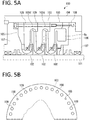
centrifugal compressor 100 of a vertical division type disclosed inPatent Literature 1, as illustrated inFIG. 5 , a plurality ofimpellers 102, in this case, threeimpellers 102 are fixed in a vertical row to arotary shaft 101, andpartition plates interstage flow path 103d are provided betweenadjacent impellers 102. Thepartition plates interstage flow path 103d runs from an outlet of theimpeller 102 of the preceding stage toward an outer diameter direction, is then folded toward an inner diameter direction, and is connected to an inlet of theimpeller 102 of the subsequent stage. Therefore, theinterstage flow path 103d has a shape guiding a fluid with reduced compression loss. - An
inlet wall 105 including a suction port 105i is provided on upstream of theimpeller 102 of a first stage, and anoutlet wall 106 including a discharge port 106o is provided on downstream of theimpeller 102 of a third stage. Vehicle compartment covers 107 and 107 that support therotary shaft 101 are provided outside theinlet wall 105 and theoutlet wall 106. - For example, holes for four assembling through
bolts 108 and holes for thirtyfixing bolts 109 are communicably provided on an outer periphery of each of thevehicle compartment cover 107 on left side in the drawing, theinlet wall 105, thepartition plates outlet wall 106, and thevehicle compartment cover 107 on right side in the drawing. The throughbolts 108 and thefixing bolts 109 extend through the corresponding holes and are rigidly fastened. - A
vehicle compartment 104 is provided and assembled on the outside of thepartition plate 103, theinlet wall 105, theoutlet wall 106, and thevehicle compartment cover 107, so as to surround and integrate these stationary members. - Patent Literature 1: Japanese Utility Model Laid-Open No.
6-83988 - According to the above-described
centrifugal compressor 100 disclosed inPatent Literature 1, outer peripheral portions of therespective partition plates fixing bolts 109. Therefore, it is said that deflection of each of thepartition plates centrifugal compressor 100 disclosed inPatent Literature 1, each of thepartition plates rotary shaft 101, which is advantageous in rotational vibration. - In the
centrifugal compressor 100, however, vibration still occurs due to rotation of therotary shaft 101 and theimpellers 102. Incidentally, the vibration is resultant vibration of vibration caused by rotation itself of therotary shaft 101 and theimpellers 102 and vibration caused by fluid compression associated with the rotation of therotary shaft 101 and theimpellers 102. - The members configuring the
centrifugal compressor 100 are required to have vibration resistance to the vibration of thecentrifugal compressor 100. Among the members, the throughbolt 108 and thefixing bolt 109 are lower in strength than the other members. Therefore, it is demanded to secure reliability preventing damage such as crack and fracture even when the throughbolt 108 and thefixing bolt 109 are used for a long term. - Accordingly, an object of the present invention is to improve vibration resistance of the fixing bolt for the stationary member used in the centrifugal compressor.
- In addition, an object of the present invention is to provide the centrifugal compressor in which the stationary member is fastened with use of such a fixing bolt for the stationary member.
- According to the present invention, there is provided a fixing bolt for a stationary member that extends through and fixes a plurality of stationary members in a multistage centrifugal compressor, and the fixing bolt for the stationary member includes a head portion, a columnar portion connected to the head portion, and a threaded portion connected to the columnar portion.
- The columnar portion according to the present invention includes one or more large diameter parts and a plurality of small diameter parts. The one or more large diameter parts correspond to a position of an antinode of a primary vibration mode of the fixing bolt for the stationary member, or to the position of the antinode of the primary vibration mode and positions of antinodes of a secondary vibration mode. Each of the plurality of small diameter parts has a diameter smaller than each of the large diameter parts.
- According to the fixing bolt for the stationary member of the present invention, since the large diameter parts corresponding to the antinodes of the vibration mode and the small diameter parts, strength of each of which is suppressed low, are provided, it is possible to reduce deflection of the columnar portion, and to suppress stress concentration to a boundary between the head portion and the columnar portion and to a boundary between the columnar portion and the threaded portion. This improves vibration resistance of the fixing bolt for the stationary member of the present invention.
- Combinations of a plurality of large diameter parts and a plurality of small diameter parts in the columnar portion of the present invention are encompassed.
- A first form of the preferred columnar portion includes a first large diameter part and first small diameter parts that are respectively disposed on both sides of the first large diameter part, and the first large diameter part corresponds to the antinode of the primary vibration mode.
- In addition, a second form of the preferred columnar portion further includes second large diameter parts that are respectively connected to the first small diameter parts, in addition to the first form, and the second large diameter parts correspond to the antinodes of the secondary vibration mode.
- Further, a third form of the preferred columnar portion further includes second small diameter parts that are respectively connected to the second large diameter parts, in addition to the second form, and at least one of the second small diameter parts is connected to the head portion or the threaded portion.
- Furthermore, a fourth form of the preferred columnar portion further includes second small diameter parts that are respectively connected to the second large diameter parts, and at least one third large diameter part that is connected to at least one of the second small diameter parts, in addition to the second form. The at least one third large diameter part is connected to the head portion or the threaded portion.
- When a restriction pin that stops displacement of the fixing bolt in an axial direction and a circumferential direction abuts on the first large diameter part to restrict the first large diameter part in a state where the fixing bolt of the present invention is used for fastening, the abutted portion becomes a node of the vibration mode. This makes it possible to suppress both of the primary vibration mode and the secondary vibration mode between the head portion and the first large diameter part and between the threaded portion and the first large diameter part, respectively.
- In addition, the preferred columnar portion according to the present invention includes one or more vibration dampers on an outer periphery.
- In this case, at least one of the first large diameter part and the first small diameter part may include one or more vibration dampers.
- Further, at least one of the second large diameter parts may include one or more vibration dampers. Moreover, at least one of the second small diameter parts may include one or more vibration dampers.
- According to the fixing bolt for the stationary member of the present invention, since the large diameter parts corresponding to the antinodes of the vibration mode and the small diameter parts, strength of each of which is suppressed low, are provided, it is possible to reduce deflection of the columnar portion, and to suppress stress concentration to the boundary between the head portion and the columnar portion and to the boundary between the columnar portion and the threaded portion. This improves vibration resistance of the fixing bolt for the stationary member of the present invention.
-
- [
FIGs. 1A and 1B] FIGs. 1A and 1B illustrate a schematic configuration of a centrifugal compressor according to an embodiment of the present invention, in whichFIG. 1A is a half vertical cross-sectional view, andFIG. 1B is a half cross-sectional view of a partition plate. - [
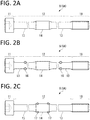
FIGs. 2A to 2C] FIGs. 2A to 2C are partial vertical cross-sectional views each illustrating a fixing bolt that fastens a stationary member of the centrifugal compressor ofFIGs. 1A and 1B , in whichFIG. 2A illustrates a basic form, andFIGs. 2B and 2C each illustrate a form in which vibration dampers are added to the form ofFIG. 2A . - [
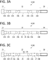
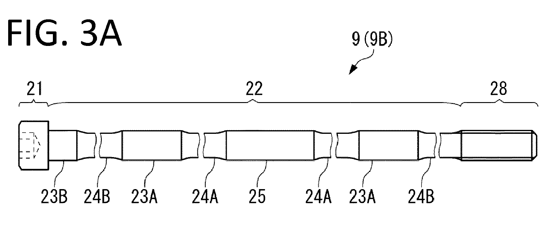
FIGs. 3A to 3C] FIGs. 3A to 3C are partial vertical cross-sectional views each illustrating another fixing bolt that fastens the stationary member of the centrifugal compressor ofFIGs. 1A and 1B , in whichFIG. 3A illustrates a basic form, andFIGs. 3B and 3C each illustrate a form in which vibration dampers are added to the form ofFIG. 3A . - [
FIGs. 4A to 4C] FIG. 4A is a diagrams illustrating the fixing bolt ofFIG. 2A and a primary vibration mode by being superposed on each other, andFIG. 4B is a diagram illustrating the fixing bolt ofFIG. 3A and a secondary vibration mode by being superposed on each other. - [
FIGs. 5A and 5B] FIGs. 5A and 5B illustrate a centrifugal compressor disclosed inPatent Literature 1, in whichFIG. 5A is a half vertical cross-sectional view, andFIG. 5B is a half cross-sectional view of a partition plate. - An embodiment of a multistage centrifugal compressor according to the present invention is described below with reference to
FIG. 1 to FIG. 4C . - A multistage
centrifugal compressor 10 according to the present embodiment has the configuration same as the configuration of thecentrifugal compressor 100 described with use ofFIG. 5 except that a configuration of a fixingbolt 9 extending through and fixing a stationary member is different from that of thecentrifugal compressor 100. Accordingly, in the following, operation of thecentrifugal compressor 10 and differences with thecentrifugal compressor 100 are mainly described. Note that arotary shaft 1 ofFIG. 1 corresponds to therotary shaft 101 ofFIG. 5 , and reference numerals of other members have similar correspondence relationship. - The operation of the
centrifugal compressor 10 illustrated inFIG. 1 is described below. - When the
rotary shaft 1 is driven by an unillustrated driver such as an electric motor coupled to therotary shaft 1 and therotary shaft 1 accordingly rotates at high speed, each ofimpellers 2 fixed to therotary shaft 1 rotates together with therotary shaft 1, and sucks a fluid such as gas from an inlet of each of theimpellers 2 and discharges the fluid from an outlet. In other words, the fluid that has been sucked into theimpeller 2 in a first stage through asuction port 5i and then discharged flows through a firstinterstage flow path 3d to theimpeller 2 in a second stage. At this time, pressure of the fluid flowing through the firstinterstage flow path 3d is higher than pressure of the fluid in thesuction port 5i by an amount of energy provided by theimpeller 2 in the first stage. Likewise, pressure of the fluid that has passed through theimpellers 2 in the second stage and a third stage respectively becomes higher than the previous pressure. Note that, in a case of compressing gas having a large molecular weight, such as carbon dioxide and butadiene, energy larger than energy of light gas is sucked to increase pressure difference even at the same rotation number by the same impellers. The fluid, the pressure of which has been successively increased, is discharged through a discharge port 6o. As described above, the fluid pressure becomes higher in order from thesuction port 5i on left side in the drawing to the discharge port 6o on right side. - When the
centrifugal compressor 10 is continuously operated, vibration is repeatedly applied to a throughbolt 8 and the fixingbolt 9. When the throughbolt 8 and the fixingbolt 9 are inserted into corresponding bolt insertion holes with no gap, deflection or runout (hereinafter, collectively referred to as deflection) caused by the vibration does not occur on the throughbolt 8 and the fixingbolt 9 even if receiving the vibration. In consideration of machining accuracy, however, it is necessary to inevitably provide a gap around the throughbolt 8 and the fixingbolt 9. Accordingly, deflection caused by the vibration occurs on the throughbolt 8 and the fixingbolt 9, and damage such as crack and fracture caused by fatigue may occur on the throughbolt 8 and the fixingbolt 9. In particular, the fixingbolt 9 is easily damaged because the fixingbolt 9 is longer in size than the throughbolt 8. The fixingbolt 9 according to the present embodiment, however, has a structure that considerably reduces occurrence of damage as described below. - As illustrated in
FIG. 2A , the fixingbolt 9 includes ahead portion 11, acolumnar portion 12 connected to thehead portion 11, and a threadedportion 18 connected to thecolumnar portion 12. A fixingbolt 9A is integrally fabricated by stainless steel or other metal material. In thefixing bolt 9A, thecolumnar portion 12 is longer than the threadedportion 18, and the form of theelongated columnar portion 12 has the feature of the fixingbolt 9A. In other words, thecolumnar portion 12 has the form in which a firstsmall diameter part 13, a firstlarge diameter part 14, and the firstsmall diameter part 13 are arranged in order from thehead portion 11 side, and the firstsmall diameter parts 13 are respectively disposed on both sides of the firstlarge diameter part 14. The firstlarge diameter part 14 has a large diameter at a center part. The firstsmall diameter part 13 has a small diameter and is constricted. The firstsmall diameter part 13 has the diameter smaller than a diameter at a top of a thread of the threadedportion 18. Thecolumnar portion 12 includes the firstsmall diameter parts large diameter part 14 for the following reason. - According to the study by the inventors, when the fixing
bolt 9A repeatedly receives vibration, a boundary between thehead portion 11 and thecolumnar portion 12 and a boundary between thecolumnar portion 12 and the threadedportion 18 are easily damaged. The easily-damaged state is not eliminated only by increasing the diameter of thecolumnar portion 12. In other words, the diameter is largely varied at the boundary between thehead portion 11 and thecolumnar portion 12, which easily causes stress concentration. In addition, at the boundary between thecolumnar portion 12 and the threadedportion 18, the threadedportion 18 engages with an unillustrated thread groove and motion thereof is restrained, whereas slight deflection may occur on thecolumnar portion 12. Therefore, the boundary between thecolumnar portion 12 and the threadedportion 18 is also easily damaged due to stress concentration. - Therefore, the fixing
bolt 9A includes the firstsmall diameter part 13 that has relatively low strength, at a part connected to thehead portion 11 and at a part connected to the threadedportion 18. In other words, causing elastic deformation preferentially at the firstsmall diameter part 13 having low strength suppresses the degree of stress concentration, which makes a structure be hardly damaged even if the stress concentration occurs at the boundary between thehead portion 11 and thecolumnar portion 12 and the boundary between thecolumnar portion 12 and the threadedportion 18. - When the
columnar portion 12 is wholly made small in diameter, however, a degree of deflection of thecolumnar portion 12 is increased. Therefore, a gap between the fixingbolt 9A and a wall surface defining the bolt insertion hole (not illustrated) is made partially small by providing the firstlarge diameter part 14 in thefixing bolt 9A, which leads to reduced deflection. - The first
large diameter part 14 is provided at a position that includes an antinode of a primary vibration mode in vibration occurred on the fixingbolt 9A, as illustrated inFIG. 4A , in addition to deflection reduction. In other words, deflection is reduced by the fact that the fixingbolt 9A includes the firstlarge diameter part 14 correspondingly provided at a position at which an amplitude of the vibration in the primary mode becomes the largest. Note that, inFIG. 4A , the primary vibration mode is illustrated by an alternate long and short dash line, and the antinode is located at a position of an upward peak. - As described above, the fixing
bolt 9A achieves the structure hard to be damaged, by deflection reduction function due to provision of the firstlarge diameter part 14, in addition to the function of suppressing the stress concentration at the boundary between thehead portion 11 and thecolumnar portion 12 and the boundary between thecolumnar portion 12 and the threadedportion 18 due to provision of the firstsmall diameter parts 13 in thecolumnar portion 12. - To make the
fixing bolt 9A hard to be damaged, as illustrated inFIG. 2B and FIG. 2C , providingvibration dampers columnar portion 12 is effective. Thevibration dampers bolt 9A and the wall surface defining the bolt insertion hole, thereby attenuating the vibration applied to the fixingbolt 9A. As illustrated inFIG. 2B and FIG. 2C , an O-ring may be used for thevibration dampers vibration dampers bolt 9A, such as an annular resin member, may be used. In addition, the term "vibration damper" does not mean that the damper completely suppress vibration. - The
vibration dampers vibration dampers 16 may be respectively provided at the firstsmall diameter parts 13 as illustrated inFIG. 2B , or thevibration dampers 17 may be provided at the firstlarge diameter part 14 as illustrated inFIG. 2C . Although not illustrated, thevibration dampers small diameter parts 13 and the firstlarge diameter part 14. - In the case where the
vibration dampers 16 are respectively provided on the firstsmall diameter parts 13 one by one as illustrated inFIG. 2B , thevibration dampers 16 are preferably provided at respective positions that are equally distanced from the center of thecolumnar portion 12 in the axial direction, namely, at symmetrical positions about the center, in consideration of positional balance with respect to vibration. - Note that the example in which the first
large diameter part 14 is disposed at the center in the axial direction is illustrated here; however, the firstlarge diameter part 14 may not be disposed at the center in some cases for the structural reasons. In other words, a distance from thehead portion 11 to the firstlarge diameter part 14 may be different from a distance from the threadedportion 18 to the firstlarge diameter part 14 in some cases. In this case, the firstlarge diameter part 14 is not the symmetric reference. Accordingly, in this case, thevibration damper 16 is desirably provided at positions at the same ratio in each of the distance from thehead portion 11 to the firstlarge diameter part 14 and the distance from the threadedportion 18 to the firstlarge diameter part 14. For example, when the distance from thehead portion 11 to the firstlarge diameter part 14 is denoted by L1, and the distance from the threadedportion 18 to the firstlarge diameter part 14 is denoted by L2, if thedamper 16 is disposed at a position of 1/2×L1 between thehead portion 11 and the firstlarge diameter part 14, thedamper 16 is disposed at a position of 1/2×L2 between the threadedportion 18 and the firstlarge diameter part 14. - Further, in the case where the
vibration dampers 17 are provided on the firstlarge diameter part 14, it is possible to dispose twovibration dampers 17 with an interval in the axial direction as illustrated inFIG. 2C . Also in this case, as withFIG. 2B , thevibration dampers 17 are preferably provided at symmetrical positions about the center in the axial direction. In the case where thevibration dampers 17 are provided on the firstlarge diameter part 14, however, only onevibration damper 17 may be provided at the center in the axial direction. - The diameter and the dimension in the axial direction of each of the first
small diameter parts 13 and the firstlarge diameter part 14 of the fixingbolt 9A are not uniquely determined, and are set according to the specification of thecentrifugal compressor 10 in which thefixing bolt 9A is used. - Among them, when the dimension in the axial direction of the first
large diameter part 14 is increased, moments at the boundary between thehead portion 11 and thecolumnar portion 12 and at the boundary between thecolumnar portion 12 and the threadedportion 18 are increased. Therefore, the firstlarge diameter part 14 preferably has a minimum dimension that secures the above-described two functions of the firstlarge diameter part 14. As an index, the dimension in the axial direction of the firstlarge diameter part 14 is preferably about 5% to about 15% of the dimension in the axial direction of thecolumnar portion 12. - The fixing
bolt 9A described above includes the firstlarge diameter part 14 correspondingly provided at the position including the antinode of the primary vibration mode; however, as illustrated inFIGS. 3A to 3C , in the present embodiment, secondlarge diameter parts - As illustrated in
FIG. 3A , a fixingbolt 9B includes ahead portion 21, acolumnar portion 22 connected to thehead portion 21, and a threadedportion 28 connected to thecolumnar portion 22. Also in the fixingbolt 9B, thecolumnar portion 22 is longer than the threadedportion 28. In thecolumnar portion 22, firstsmall diameter parts large diameter part 25, and the secondlarge diameter parts small diameter parts large diameter parts small diameter parts large diameter parts small diameter part 24B (on right side in drawing) is connected to the threadedportion 28. The other secondsmall diameter part 24B (on left side in the drawing) is connected to a thirdlarge diameter part 23B, and the thirdlarge diameter part 23B is connected to thehead portion 21. - As illustrated in
FIG. 4B , in the fixingbolt 9B, each of the secondlarge diameter parts large diameter part 25 in the axial direction is provided at the position including the antinode of the secondary vibration mode. In other words, the fixingbolt 9B makes it possible to reduce vibration in both of the primary vibration mode and the secondary vibration mode. - Note that, in
FIG. 4B , the secondary vibration mode is illustrated by an alternate long and short dash line, and the antinode is located at each of two positions of an upward peak and a downward peak. - In addition, in the fixing
bolt 9B, the thirdlarge diameter part 23B is connected to thehead portion 21, and the fixingbolt 9B is different from the fixingbolt 9B in which the firstsmall diameter part 13 is connected to thehead portion 11. This is because, even if stress concentration occurs on the boundary between thehead portion 21 and the thirdlarge diameter part 23B, providing the thirdlarge diameter part 23B enhances the strength of the boundary to avoid damage. On the other hand, the secondsmall diameter part 24B is connected to the thirdlarge diameter part 23B, which causes elastic deformation in the secondsmall diameter part 24B to suppress stress concentration to the boundary between thehead portion 21 and the thirdlarge diameter part 23B. - As illustrated in
FIG. 3B and FIG. 3C ,vibration dampers bolt 9B. InFIG. 3B , onevibration damper 26 is provided at the center of the firstlarge diameter part 25, and thevibration damper 26 is disposed corresponding to the antinode of the primary vibration mode. Further, inFIG. 3C ,vibration dampers 26 are respectively disposed, one by one, at the centers in the axial direction of the secondlarge diameter parts FIG. 3C , arestriction pin 29 that stops displacement of the fixingbolt 9B in the axial direction and a circumferential direction abuts on the center in the axial direction of the firstlarge diameter part 25, and avibration damper 27 is disposed in each of the secondlarge diameter parts restriction pin 29.FIG. 4C illustrates the vibration mode when therestriction pin 29 is provided. Note that, inFIG. 4C , the primary vibration mode is illustrated by an alternate long and short dash line, and the secondary vibration mode is illustrated by an alternate long and two short dashes line. As illustrated inFIG. 4C , the secondlarge diameter parts vibration dampers restriction pin 29 in the axial direction. - According to the above-described fixing bolt 9 (9A or 9B), the following effects are achievable.
- Since the fixing
bolt 9A includes the firstlarge diameter part 14 corresponding to the antinode of the primary vibration mode, and includes the firstsmall diameter parts columnar portion 12, and to suppress stress concentration to the boundary between thehead portion 11 and thecolumnar portion 12 and to the boundary between thecolumnar portion 12 and the threadedportion 18. Since the fixingbolt 9B includes the secondlarge diameter parts columnar portion 22, in addition to achievement of the effects similar to those by the fixingbolt 9A. Accordingly, the fixingbolt 9A and the fixingbolt 9B make it possible to reduce occurrence of crack and fracture, and to improve vibration resistance. - Further, the fixing
bolt 9 including thevibration dampers bolt 9 including thevibration dampers vibration dampers - Although the present invention is described above on the basis of the fixing
bolt 9 and the fixingbolt 9 that are preferred embodiments, the present invention is not limited to the embodiments. - In the present embodiment, out of the through
bolt 8 and the fixingbolt 9 that fasten the stationary member, the fixingbolt 9 has been described. As for the throughbolt 8, the small diameter part and the large diameter part may be provided in the columnar portion and the large diameter part may correspond to the antinode of the vibration mode, as with the fixingbolt 9. In other words, the throughbolt 8 and the fixingbolt 9 have been discriminated and described in the present embodiment; however, both of the throughbolt 8 and the fixingbolt 9 may include the large diameter part corresponding to the antinode of the vibration mode and the small diameter part, the strength of which is suppressed low. - Further, the number and the arrangement of each of the large diameter parts and the small diameter parts are optional. In other words, the optional number and the optional arrangement are also included in the present invention as long as one or more large diameter parts that correspond to the position of the antinode of the primary vibration mode of the fixing
bolt 9, or to the position of the antinode of the primary vibration mode and the positions of the antinodes of the secondary vibration mode, and a plurality of small diameter parts each having a diameter smaller than the large diameter parts are included. Among them, the fixingbolt 9A illustrated inFIG. 2 and the fixingbolt 9B illustrated inFIG. 3 are preferable forms of the present invention. - Moreover, the positions at which the
vibration dampers -
- 1
- Rotary shaft
- 2
- Impeller
- 3
- Partition plate
- 3d
- Interstage flow path
- 4
- Vehicle compartment
- 5
- Inlet wall
- 5i
- Suction port
- 6
- Outlet wall
- 6o
- Discharge port
- 7
- Vehicle compartment cover
- 8
- Bolt
- 9
- Fixing bolt
- 9A
- Fixing bolt
- 9B
- Fixing bolt
- 10
- Centrifugal compressor
- 11
- Head portion
- 12
- Columnar portion
- 13
- First small diameter part
- 14
- First large diameter part
- 18
- Threaded portion
- 21
- Head portion
- 22
- Columnar portion
- 23A
- Second large diameter part
- 23B
- Third large diameter part
- 24A
- First small diameter part
- 24B
- Second small diameter part
- 25
- First large diameter part
- 28
- Threaded portion
- 29
- Restriction pin
Claims (10)
- A fixing bolt for a stationary member, the bolt extending through and fixing a plurality of stationary members in a multistage centrifugal compressor, the bolt comprising:a head portion;a columnar portion connected to the head portion; anda threaded portion connected to the columnar portion, whereinthe columnar portion includes one or more large diameter parts and a plurality of small diameter parts, the one or more large diameter parts each corresponding to a position of an antinode of a primary vibration mode of the fixing bolt for the stationary member, or to the position of the antinode of the primary vibration mode and positions of antinodes of a secondary vibration mode, and each of the plurality of small diameter parts having a diameter smaller than each of the large diameter parts.
- The fixing bolt for the stationary member according to claim 1, wherein
the columnar portion includes a first large diameter part and first small diameter parts that are respectively disposed on both sides of the first large diameter part, and
the first large diameter part corresponds to the antinode of the primary vibration mode. - The fixing bolt for the stationary member according to claim 2, wherein
the columnar portion further includes second large diameter parts that are respectively connected to the first small diameter parts, and
the second large diameter parts correspond to the antinodes of the secondary vibration mode. - The fixing bolt for the stationary member according to claim 3, wherein
the columnar portion further includes second small diameter parts that are respectively connected to the second large diameter parts, and
at least one of the second small diameter parts is connected to the head portion or the threaded portion. - The fixing bolt for the stationary member according to claim 3, wherein
the columnar portion further includes second small diameter parts that are respectively connected to the second large diameter parts, and at least one third large diameter part that is connected to at least one of the second small diameter parts, and
the at least one third large diameter part is connected to the head portion or the threaded portion. - The fixing bolt for the stationary member according to claim 1, wherein the columnar portion includes one or more vibration dampers on an outer periphery.
- The fixing bolt for the stationary member according to claim 2, wherein at least one of the first large diameter part and the first small diameter part includes one or more vibration dampers.
- The fixing bolt for the stationary member according to claim 3, wherein at least one of the second large diameter parts includes one or more vibration dampers.
- The fixing bolt for the stationary member according to claim 4, wherein at least one of the second small diameter parts includes one or more vibration dampers.
- A centrifugal compressor, wherein the fixing bolt according to any one of claims 1 to 9 extends through and fixes the plurality of stationary members.
Applications Claiming Priority (1)
| Application Number | Priority Date | Filing Date | Title |
|---|---|---|---|
| PCT/JP2015/005927 WO2017090073A1 (en) | 2015-11-27 | 2015-11-27 | Fixing bolt for stationary member, and centrifugal compressor |
Publications (3)
| Publication Number | Publication Date |
|---|---|
| EP3346140A1 true EP3346140A1 (en) | 2018-07-11 |
| EP3346140A4 EP3346140A4 (en) | 2018-10-17 |
| EP3346140B1 EP3346140B1 (en) | 2019-11-06 |
Family
ID=58763215
Family Applications (1)
| Application Number | Title | Priority Date | Filing Date |
|---|---|---|---|
| EP15909192.5A Active EP3346140B1 (en) | 2015-11-27 | 2015-11-27 | Fixing bolt for stationary member, and centrifugal compressor |
Country Status (4)
| Country | Link |
|---|---|
| US (1) | US10801506B2 (en) |
| EP (1) | EP3346140B1 (en) |
| JP (1) | JP6626900B2 (en) |
| WO (1) | WO2017090073A1 (en) |
Family Cites Families (19)
| Publication number | Priority date | Publication date | Assignee | Title |
|---|---|---|---|---|
| US3118386A (en) * | 1964-01-21 | Multi-stage centrifugal pump | ||
| US890662A (en) * | 1907-03-19 | 1908-06-16 | Carl Lager | Multistage centrifugal pump. |
| US1516110A (en) * | 1923-01-22 | 1924-11-18 | Mackley Edward Norman | Multistage centrifugal pump |
| US2514865A (en) * | 1945-04-13 | 1950-07-11 | Ingersoll Rand Co | Pumping unit |
| CH267487A (en) * | 1945-12-19 | 1950-03-31 | Power Jets Res & Dev Ltd | Rotor for multistage axial flow machines. |
| US2650017A (en) | 1948-11-26 | 1953-08-25 | Westinghouse Electric Corp | Gas turbine apparatus |
| GB933185A (en) * | 1959-10-02 | 1963-08-08 | Klein Schanzlin & Becker Ag | Multi-stage centrifugal pump |
| US3070348A (en) | 1960-07-25 | 1962-12-25 | Gen Motors Corp | Composite rotor |
| US3051090A (en) * | 1960-08-04 | 1962-08-28 | Worthington Corp | Segmented casing for multistage centrifugal fluid machines |
| JPS63173508U (en) * | 1987-05-01 | 1988-11-10 | ||
| JPH0732683Y2 (en) * | 1987-05-06 | 1995-07-31 | 積水ハウス株式会社 | Reinforcement structure such as wall surfaces |
| US5087172A (en) * | 1989-02-13 | 1992-02-11 | Dresser-Rand Company, A General Partnership | Compressor cartridge seal method |
| JP2573181Y2 (en) * | 1993-04-07 | 1998-05-28 | 石川島播磨重工業株式会社 | Rotor vibration prevention device |
| JPH0683988U (en) * | 1993-05-18 | 1994-12-02 | 三菱重工業株式会社 | Multi-stage centrifugal compressor |
| JP3664844B2 (en) * | 1997-04-25 | 2005-06-29 | 三菱重工業株式会社 | Tie bolt structure of internal combustion engine |
| DE102008008887A1 (en) * | 2008-02-13 | 2009-08-27 | Man Turbo Ag | Multi-piece bladed rotor for a turbomachine |
| JP2009286354A (en) | 2008-05-30 | 2009-12-10 | Yamaha Motor Co Ltd | Engine suspension structure for vehicle and motorcycle equipped with it |
| JP2010223292A (en) * | 2009-03-23 | 2010-10-07 | Honda Motor Co Ltd | tightening structure |
| JP6124659B2 (en) * | 2013-04-15 | 2017-05-10 | 株式会社日立製作所 | Multistage centrifugal fluid machine |
-
2015
- 2015-11-27 EP EP15909192.5A patent/EP3346140B1/en active Active
- 2015-11-27 US US15/765,625 patent/US10801506B2/en active Active
- 2015-11-27 WO PCT/JP2015/005927 patent/WO2017090073A1/en not_active Ceased
- 2015-11-27 JP JP2017552547A patent/JP6626900B2/en active Active
Also Published As
| Publication number | Publication date |
|---|---|
| US20180306194A1 (en) | 2018-10-25 |
| JPWO2017090073A1 (en) | 2018-07-19 |
| US10801506B2 (en) | 2020-10-13 |
| EP3346140B1 (en) | 2019-11-06 |
| WO2017090073A1 (en) | 2017-06-01 |
| EP3346140A4 (en) | 2018-10-17 |
| JP6626900B2 (en) | 2019-12-25 |
Similar Documents
| Publication | Publication Date | Title |
|---|---|---|
| RU2459120C2 (en) | Gas-turbine engine fan | |
| US8147191B2 (en) | Damping device for turbomachine stator | |
| US8322991B2 (en) | Balance weight | |
| RU2683343C1 (en) | Fan for turbomachine | |
| US10408233B2 (en) | Rotor in blisk or bling design of an aircraft engine | |
| US7871243B2 (en) | Augmented vaneless diffuser containment | |
| AU2014228703B2 (en) | Vane arrangement having alternating vanes with different trailing edge profile | |
| US10458430B2 (en) | Centrifugal-compressor casing and centrifugal compressor | |
| KR20180101459A (en) | Engine cooling fan casting shroud with unobstructed outlet | |
| RU2631585C2 (en) | Compressor stator for turbomachine | |
| EP2878796A1 (en) | Engine duct and aircraft engine | |
| US11002140B2 (en) | Guide vane segment | |
| JP2009264205A (en) | Centrifugal compressor | |
| US11255345B2 (en) | Method and arrangement to minimize noise and excitation of structures due to cavity acoustic modes | |
| RU2619914C2 (en) | Sector of stator blades, axial turbomachine stator, axial turbomachine | |
| US10550720B2 (en) | Guide vane segment | |
| KR101540403B1 (en) | Centrifugal Impeller Having External Blade and Pump thereof | |
| US8632300B2 (en) | Energy absorbing apparatus in a gas turbine engine | |
| US10060275B2 (en) | Turbomachine blade arrangement with first and second guides with respective movable first and second elements to reduce vibrational response | |
| EP3346140B1 (en) | Fixing bolt for stationary member, and centrifugal compressor | |
| JP5405884B2 (en) | Turbomachine barrel type casing and head cover mounting structure | |
| JP2013505386A (en) | Axial flow centrifugal turbomachine | |
| EP3073091A1 (en) | Compressor | |
| JP2006022812A (en) | Reinforcing material for low-pressure compressors for aircraft engines | |
| JP6079041B2 (en) | Turbomolecular pump and reinforcing member for turbomolecular pump |
Legal Events
| Date | Code | Title | Description |
|---|---|---|---|
| STAA | Information on the status of an ep patent application or granted ep patent |
Free format text: STATUS: THE INTERNATIONAL PUBLICATION HAS BEEN MADE |
|
| PUAI | Public reference made under article 153(3) epc to a published international application that has entered the european phase |
Free format text: ORIGINAL CODE: 0009012 |
|
| STAA | Information on the status of an ep patent application or granted ep patent |
Free format text: STATUS: REQUEST FOR EXAMINATION WAS MADE |
|
| 17P | Request for examination filed |
Effective date: 20180403 |
|
| AK | Designated contracting states |
Kind code of ref document: A1 Designated state(s): AL AT BE BG CH CY CZ DE DK EE ES FI FR GB GR HR HU IE IS IT LI LT LU LV MC MK MT NL NO PL PT RO RS SE SI SK SM TR |
|
| AX | Request for extension of the european patent |
Extension state: BA ME |
|
| A4 | Supplementary search report drawn up and despatched |
Effective date: 20180917 |
|
| RIC1 | Information provided on ipc code assigned before grant |
Ipc: F04D 17/12 20060101ALI20180911BHEP Ipc: F04D 29/62 20060101AFI20180911BHEP |
|
| DAV | Request for validation of the european patent (deleted) | ||
| DAX | Request for extension of the european patent (deleted) | ||
| REG | Reference to a national code |
Ref country code: DE Ref legal event code: R079 Ref document number: 602015041459 Country of ref document: DE Free format text: PREVIOUS MAIN CLASS: F04D0029620000 Ipc: F04D0017120000 |
|
| GRAP | Despatch of communication of intention to grant a patent |
Free format text: ORIGINAL CODE: EPIDOSNIGR1 |
|
| STAA | Information on the status of an ep patent application or granted ep patent |
Free format text: STATUS: GRANT OF PATENT IS INTENDED |
|
| RIC1 | Information provided on ipc code assigned before grant |
Ipc: F04D 17/12 20060101AFI20190516BHEP Ipc: F04D 29/62 20060101ALI20190516BHEP Ipc: F04D 29/42 20060101ALI20190516BHEP |
|
| INTG | Intention to grant announced |
Effective date: 20190529 |
|
| GRAS | Grant fee paid |
Free format text: ORIGINAL CODE: EPIDOSNIGR3 |
|
| GRAA | (expected) grant |
Free format text: ORIGINAL CODE: 0009210 |
|
| STAA | Information on the status of an ep patent application or granted ep patent |
Free format text: STATUS: THE PATENT HAS BEEN GRANTED |
|
| AK | Designated contracting states |
Kind code of ref document: B1 Designated state(s): AL AT BE BG CH CY CZ DE DK EE ES FI FR GB GR HR HU IE IS IT LI LT LU LV MC MK MT NL NO PL PT RO RS SE SI SK SM TR |
|
| REG | Reference to a national code |
Ref country code: GB Ref legal event code: FG4D |
|
| REG | Reference to a national code |
Ref country code: CH Ref legal event code: EP Ref country code: AT Ref legal event code: REF Ref document number: 1199065 Country of ref document: AT Kind code of ref document: T Effective date: 20191115 |
|
| REG | Reference to a national code |
Ref country code: IE Ref legal event code: FG4D |
|
| REG | Reference to a national code |
Ref country code: DE Ref legal event code: R096 Ref document number: 602015041459 Country of ref document: DE |
|
| REG | Reference to a national code |
Ref country code: NL Ref legal event code: MP Effective date: 20191106 |
|
| REG | Reference to a national code |
Ref country code: LT Ref legal event code: MG4D |
|
| PG25 | Lapsed in a contracting state [announced via postgrant information from national office to epo] |
Ref country code: PT Free format text: LAPSE BECAUSE OF FAILURE TO SUBMIT A TRANSLATION OF THE DESCRIPTION OR TO PAY THE FEE WITHIN THE PRESCRIBED TIME-LIMIT Effective date: 20200306 Ref country code: NL Free format text: LAPSE BECAUSE OF FAILURE TO SUBMIT A TRANSLATION OF THE DESCRIPTION OR TO PAY THE FEE WITHIN THE PRESCRIBED TIME-LIMIT Effective date: 20191106 Ref country code: LT Free format text: LAPSE BECAUSE OF FAILURE TO SUBMIT A TRANSLATION OF THE DESCRIPTION OR TO PAY THE FEE WITHIN THE PRESCRIBED TIME-LIMIT Effective date: 20191106 Ref country code: NO Free format text: LAPSE BECAUSE OF FAILURE TO SUBMIT A TRANSLATION OF THE DESCRIPTION OR TO PAY THE FEE WITHIN THE PRESCRIBED TIME-LIMIT Effective date: 20200206 Ref country code: GR Free format text: LAPSE BECAUSE OF FAILURE TO SUBMIT A TRANSLATION OF THE DESCRIPTION OR TO PAY THE FEE WITHIN THE PRESCRIBED TIME-LIMIT Effective date: 20200207 Ref country code: PL Free format text: LAPSE BECAUSE OF FAILURE TO SUBMIT A TRANSLATION OF THE DESCRIPTION OR TO PAY THE FEE WITHIN THE PRESCRIBED TIME-LIMIT Effective date: 20191106 Ref country code: FI Free format text: LAPSE BECAUSE OF FAILURE TO SUBMIT A TRANSLATION OF THE DESCRIPTION OR TO PAY THE FEE WITHIN THE PRESCRIBED TIME-LIMIT Effective date: 20191106 Ref country code: BG Free format text: LAPSE BECAUSE OF FAILURE TO SUBMIT A TRANSLATION OF THE DESCRIPTION OR TO PAY THE FEE WITHIN THE PRESCRIBED TIME-LIMIT Effective date: 20200206 Ref country code: SE Free format text: LAPSE BECAUSE OF FAILURE TO SUBMIT A TRANSLATION OF THE DESCRIPTION OR TO PAY THE FEE WITHIN THE PRESCRIBED TIME-LIMIT Effective date: 20191106 Ref country code: LV Free format text: LAPSE BECAUSE OF FAILURE TO SUBMIT A TRANSLATION OF THE DESCRIPTION OR TO PAY THE FEE WITHIN THE PRESCRIBED TIME-LIMIT Effective date: 20191106 |
|
| PG25 | Lapsed in a contracting state [announced via postgrant information from national office to epo] |
Ref country code: RS Free format text: LAPSE BECAUSE OF FAILURE TO SUBMIT A TRANSLATION OF THE DESCRIPTION OR TO PAY THE FEE WITHIN THE PRESCRIBED TIME-LIMIT Effective date: 20191106 Ref country code: HR Free format text: LAPSE BECAUSE OF FAILURE TO SUBMIT A TRANSLATION OF THE DESCRIPTION OR TO PAY THE FEE WITHIN THE PRESCRIBED TIME-LIMIT Effective date: 20191106 Ref country code: IS Free format text: LAPSE BECAUSE OF FAILURE TO SUBMIT A TRANSLATION OF THE DESCRIPTION OR TO PAY THE FEE WITHIN THE PRESCRIBED TIME-LIMIT Effective date: 20200306 |
|
| PG25 | Lapsed in a contracting state [announced via postgrant information from national office to epo] |
Ref country code: AL Free format text: LAPSE BECAUSE OF FAILURE TO SUBMIT A TRANSLATION OF THE DESCRIPTION OR TO PAY THE FEE WITHIN THE PRESCRIBED TIME-LIMIT Effective date: 20191106 |
|
| REG | Reference to a national code |
Ref country code: CH Ref legal event code: PL |
|
| PG25 | Lapsed in a contracting state [announced via postgrant information from national office to epo] |
Ref country code: EE Free format text: LAPSE BECAUSE OF FAILURE TO SUBMIT A TRANSLATION OF THE DESCRIPTION OR TO PAY THE FEE WITHIN THE PRESCRIBED TIME-LIMIT Effective date: 20191106 Ref country code: LI Free format text: LAPSE BECAUSE OF NON-PAYMENT OF DUE FEES Effective date: 20191130 Ref country code: DK Free format text: LAPSE BECAUSE OF FAILURE TO SUBMIT A TRANSLATION OF THE DESCRIPTION OR TO PAY THE FEE WITHIN THE PRESCRIBED TIME-LIMIT Effective date: 20191106 Ref country code: LU Free format text: LAPSE BECAUSE OF NON-PAYMENT OF DUE FEES Effective date: 20191127 Ref country code: CZ Free format text: LAPSE BECAUSE OF FAILURE TO SUBMIT A TRANSLATION OF THE DESCRIPTION OR TO PAY THE FEE WITHIN THE PRESCRIBED TIME-LIMIT Effective date: 20191106 Ref country code: CH Free format text: LAPSE BECAUSE OF NON-PAYMENT OF DUE FEES Effective date: 20191130 Ref country code: RO Free format text: LAPSE BECAUSE OF FAILURE TO SUBMIT A TRANSLATION OF THE DESCRIPTION OR TO PAY THE FEE WITHIN THE PRESCRIBED TIME-LIMIT Effective date: 20191106 |
|
| REG | Reference to a national code |
Ref country code: DE Ref legal event code: R097 Ref document number: 602015041459 Country of ref document: DE |
|
| REG | Reference to a national code |
Ref country code: AT Ref legal event code: MK05 Ref document number: 1199065 Country of ref document: AT Kind code of ref document: T Effective date: 20191106 |
|
| REG | Reference to a national code |
Ref country code: BE Ref legal event code: MM Effective date: 20191130 |
|
| PG25 | Lapsed in a contracting state [announced via postgrant information from national office to epo] |
Ref country code: MC Free format text: LAPSE BECAUSE OF FAILURE TO SUBMIT A TRANSLATION OF THE DESCRIPTION OR TO PAY THE FEE WITHIN THE PRESCRIBED TIME-LIMIT Effective date: 20191106 Ref country code: SK Free format text: LAPSE BECAUSE OF FAILURE TO SUBMIT A TRANSLATION OF THE DESCRIPTION OR TO PAY THE FEE WITHIN THE PRESCRIBED TIME-LIMIT Effective date: 20191106 Ref country code: SM Free format text: LAPSE BECAUSE OF FAILURE TO SUBMIT A TRANSLATION OF THE DESCRIPTION OR TO PAY THE FEE WITHIN THE PRESCRIBED TIME-LIMIT Effective date: 20191106 |
|
| PLBE | No opposition filed within time limit |
Free format text: ORIGINAL CODE: 0009261 |
|
| STAA | Information on the status of an ep patent application or granted ep patent |
Free format text: STATUS: NO OPPOSITION FILED WITHIN TIME LIMIT |
|
| 26N | No opposition filed |
Effective date: 20200807 |
|
| GBPC | Gb: european patent ceased through non-payment of renewal fee |
Effective date: 20200206 |
|
| PG25 | Lapsed in a contracting state [announced via postgrant information from national office to epo] |
Ref country code: IE Free format text: LAPSE BECAUSE OF NON-PAYMENT OF DUE FEES Effective date: 20191127 Ref country code: ES Free format text: LAPSE BECAUSE OF FAILURE TO SUBMIT A TRANSLATION OF THE DESCRIPTION OR TO PAY THE FEE WITHIN THE PRESCRIBED TIME-LIMIT Effective date: 20191106 Ref country code: FR Free format text: LAPSE BECAUSE OF NON-PAYMENT OF DUE FEES Effective date: 20200106 |
|
| PG25 | Lapsed in a contracting state [announced via postgrant information from national office to epo] |
Ref country code: SI Free format text: LAPSE BECAUSE OF FAILURE TO SUBMIT A TRANSLATION OF THE DESCRIPTION OR TO PAY THE FEE WITHIN THE PRESCRIBED TIME-LIMIT Effective date: 20191106 Ref country code: AT Free format text: LAPSE BECAUSE OF FAILURE TO SUBMIT A TRANSLATION OF THE DESCRIPTION OR TO PAY THE FEE WITHIN THE PRESCRIBED TIME-LIMIT Effective date: 20191106 Ref country code: BE Free format text: LAPSE BECAUSE OF NON-PAYMENT OF DUE FEES Effective date: 20191130 |
|
| PG25 | Lapsed in a contracting state [announced via postgrant information from national office to epo] |
Ref country code: GB Free format text: LAPSE BECAUSE OF NON-PAYMENT OF DUE FEES Effective date: 20200206 |
|
| PG25 | Lapsed in a contracting state [announced via postgrant information from national office to epo] |
Ref country code: CY Free format text: LAPSE BECAUSE OF FAILURE TO SUBMIT A TRANSLATION OF THE DESCRIPTION OR TO PAY THE FEE WITHIN THE PRESCRIBED TIME-LIMIT Effective date: 20191106 |
|
| PG25 | Lapsed in a contracting state [announced via postgrant information from national office to epo] |
Ref country code: MT Free format text: LAPSE BECAUSE OF FAILURE TO SUBMIT A TRANSLATION OF THE DESCRIPTION OR TO PAY THE FEE WITHIN THE PRESCRIBED TIME-LIMIT Effective date: 20191106 Ref country code: HU Free format text: LAPSE BECAUSE OF FAILURE TO SUBMIT A TRANSLATION OF THE DESCRIPTION OR TO PAY THE FEE WITHIN THE PRESCRIBED TIME-LIMIT; INVALID AB INITIO Effective date: 20151127 |
|
| PG25 | Lapsed in a contracting state [announced via postgrant information from national office to epo] |
Ref country code: TR Free format text: LAPSE BECAUSE OF FAILURE TO SUBMIT A TRANSLATION OF THE DESCRIPTION OR TO PAY THE FEE WITHIN THE PRESCRIBED TIME-LIMIT Effective date: 20191106 |
|
| PG25 | Lapsed in a contracting state [announced via postgrant information from national office to epo] |
Ref country code: MK Free format text: LAPSE BECAUSE OF FAILURE TO SUBMIT A TRANSLATION OF THE DESCRIPTION OR TO PAY THE FEE WITHIN THE PRESCRIBED TIME-LIMIT Effective date: 20191106 |
|
| PGFP | Annual fee paid to national office [announced via postgrant information from national office to epo] |
Ref country code: DE Payment date: 20250930 Year of fee payment: 11 |
|
| PGFP | Annual fee paid to national office [announced via postgrant information from national office to epo] |
Ref country code: IT Payment date: 20251022 Year of fee payment: 11 |