EP3346135A1 - Compressor - Google Patents
Compressor Download PDFInfo
- Publication number
- EP3346135A1 EP3346135A1 EP16841941.4A EP16841941A EP3346135A1 EP 3346135 A1 EP3346135 A1 EP 3346135A1 EP 16841941 A EP16841941 A EP 16841941A EP 3346135 A1 EP3346135 A1 EP 3346135A1
- Authority
- EP
- European Patent Office
- Prior art keywords
- shaft
- gear
- housing
- end surface
- shafts
- Prior art date
- Legal status (The legal status is an assumption and is not a legal conclusion. Google has not performed a legal analysis and makes no representation as to the accuracy of the status listed.)
- Withdrawn
Links
Images



Classifications
-
- F—MECHANICAL ENGINEERING; LIGHTING; HEATING; WEAPONS; BLASTING
- F04—POSITIVE - DISPLACEMENT MACHINES FOR LIQUIDS; PUMPS FOR LIQUIDS OR ELASTIC FLUIDS
- F04D—NON-POSITIVE-DISPLACEMENT PUMPS
- F04D25/00—Pumping installations or systems
- F04D25/16—Combinations of two or more pumps ; Producing two or more separate gas flows
- F04D25/163—Combinations of two or more pumps ; Producing two or more separate gas flows driven by a common gearing arrangement
-
- F—MECHANICAL ENGINEERING; LIGHTING; HEATING; WEAPONS; BLASTING
- F04—POSITIVE - DISPLACEMENT MACHINES FOR LIQUIDS; PUMPS FOR LIQUIDS OR ELASTIC FLUIDS
- F04D—NON-POSITIVE-DISPLACEMENT PUMPS
- F04D17/00—Radial-flow pumps, e.g. centrifugal pumps; Helico-centrifugal pumps
- F04D17/08—Centrifugal pumps
- F04D17/10—Centrifugal pumps for compressing or evacuating
- F04D17/12—Multi-stage pumps
-
- F—MECHANICAL ENGINEERING; LIGHTING; HEATING; WEAPONS; BLASTING
- F04—POSITIVE - DISPLACEMENT MACHINES FOR LIQUIDS; PUMPS FOR LIQUIDS OR ELASTIC FLUIDS
- F04D—NON-POSITIVE-DISPLACEMENT PUMPS
- F04D25/00—Pumping installations or systems
- F04D25/16—Combinations of two or more pumps ; Producing two or more separate gas flows
-
- F—MECHANICAL ENGINEERING; LIGHTING; HEATING; WEAPONS; BLASTING
- F04—POSITIVE - DISPLACEMENT MACHINES FOR LIQUIDS; PUMPS FOR LIQUIDS OR ELASTIC FLUIDS
- F04D—NON-POSITIVE-DISPLACEMENT PUMPS
- F04D29/00—Details, component parts, or accessories
- F04D29/05—Shafts or bearings, or assemblies thereof, specially adapted for elastic fluid pumps
- F04D29/053—Shafts
-
- F—MECHANICAL ENGINEERING; LIGHTING; HEATING; WEAPONS; BLASTING
- F04—POSITIVE - DISPLACEMENT MACHINES FOR LIQUIDS; PUMPS FOR LIQUIDS OR ELASTIC FLUIDS
- F04D—NON-POSITIVE-DISPLACEMENT PUMPS
- F04D29/00—Details, component parts, or accessories
- F04D29/05—Shafts or bearings, or assemblies thereof, specially adapted for elastic fluid pumps
- F04D29/056—Bearings
-
- F—MECHANICAL ENGINEERING; LIGHTING; HEATING; WEAPONS; BLASTING
- F04—POSITIVE - DISPLACEMENT MACHINES FOR LIQUIDS; PUMPS FOR LIQUIDS OR ELASTIC FLUIDS
- F04D—NON-POSITIVE-DISPLACEMENT PUMPS
- F04D29/00—Details, component parts, or accessories
- F04D29/40—Casings; Connections of working fluid
- F04D29/42—Casings; Connections of working fluid for radial or helico-centrifugal pumps
- F04D29/4206—Casings; Connections of working fluid for radial or helico-centrifugal pumps especially adapted for elastic fluid pumps
-
- F—MECHANICAL ENGINEERING; LIGHTING; HEATING; WEAPONS; BLASTING
- F04—POSITIVE - DISPLACEMENT MACHINES FOR LIQUIDS; PUMPS FOR LIQUIDS OR ELASTIC FLUIDS
- F04D—NON-POSITIVE-DISPLACEMENT PUMPS
- F04D29/00—Details, component parts, or accessories
- F04D29/60—Mounting; Assembling; Disassembling
- F04D29/62—Mounting; Assembling; Disassembling of radial or helico-centrifugal pumps
- F04D29/624—Mounting; Assembling; Disassembling of radial or helico-centrifugal pumps especially adapted for elastic fluid pumps
-
- F—MECHANICAL ENGINEERING; LIGHTING; HEATING; WEAPONS; BLASTING
- F16—ENGINEERING ELEMENTS AND UNITS; GENERAL MEASURES FOR PRODUCING AND MAINTAINING EFFECTIVE FUNCTIONING OF MACHINES OR INSTALLATIONS; THERMAL INSULATION IN GENERAL
- F16H—GEARING
- F16H1/00—Toothed gearings for conveying rotary motion
- F16H1/02—Toothed gearings for conveying rotary motion without gears having orbital motion
- F16H1/20—Toothed gearings for conveying rotary motion without gears having orbital motion involving more than two intermeshing members
- F16H1/22—Toothed gearings for conveying rotary motion without gears having orbital motion involving more than two intermeshing members with a plurality of driving or driven shafts; with arrangements for dividing torque between two or more intermediate shafts
- F16H1/227—Toothed gearings for conveying rotary motion without gears having orbital motion involving more than two intermeshing members with a plurality of driving or driven shafts; with arrangements for dividing torque between two or more intermediate shafts comprising two or more gearwheels in mesh with the same internally toothed wheel
-
- F—MECHANICAL ENGINEERING; LIGHTING; HEATING; WEAPONS; BLASTING
- F16—ENGINEERING ELEMENTS AND UNITS; GENERAL MEASURES FOR PRODUCING AND MAINTAINING EFFECTIVE FUNCTIONING OF MACHINES OR INSTALLATIONS; THERMAL INSULATION IN GENERAL
- F16H—GEARING
- F16H57/00—General details of gearing
- F16H57/02—Gearboxes; Mounting gearing therein
- F16H57/021—Shaft support structures, e.g. partition walls, bearing eyes, casing walls or covers with bearings
- F16H57/022—Adjustment of gear shafts or bearings
-
- F—MECHANICAL ENGINEERING; LIGHTING; HEATING; WEAPONS; BLASTING
- F16—ENGINEERING ELEMENTS AND UNITS; GENERAL MEASURES FOR PRODUCING AND MAINTAINING EFFECTIVE FUNCTIONING OF MACHINES OR INSTALLATIONS; THERMAL INSULATION IN GENERAL
- F16H—GEARING
- F16H57/00—General details of gearing
- F16H57/02—Gearboxes; Mounting gearing therein
- F16H57/023—Mounting or installation of gears or shafts in the gearboxes, e.g. methods or means for assembly
-
- F—MECHANICAL ENGINEERING; LIGHTING; HEATING; WEAPONS; BLASTING
- F16—ENGINEERING ELEMENTS AND UNITS; GENERAL MEASURES FOR PRODUCING AND MAINTAINING EFFECTIVE FUNCTIONING OF MACHINES OR INSTALLATIONS; THERMAL INSULATION IN GENERAL
- F16H—GEARING
- F16H57/00—General details of gearing
- F16H57/02—Gearboxes; Mounting gearing therein
- F16H2057/02039—Gearboxes for particular applications
-
- F—MECHANICAL ENGINEERING; LIGHTING; HEATING; WEAPONS; BLASTING
- F16—ENGINEERING ELEMENTS AND UNITS; GENERAL MEASURES FOR PRODUCING AND MAINTAINING EFFECTIVE FUNCTIONING OF MACHINES OR INSTALLATIONS; THERMAL INSULATION IN GENERAL
- F16H—GEARING
- F16H57/00—General details of gearing
- F16H57/02—Gearboxes; Mounting gearing therein
- F16H57/021—Shaft support structures, e.g. partition walls, bearing eyes, casing walls or covers with bearings
- F16H57/022—Adjustment of gear shafts or bearings
- F16H2057/0222—Lateral adjustment
- F16H2057/0224—Lateral adjustment using eccentric bushes
Definitions
- the present invention relates to a compressor.
- Patent Document 1 describes a three-stage compressor.
- the compressor includes a motor, an input shaft having an input gear, a first pinion shaft having a first-second stage pinion gear, a second pinion shaft having a three stage pinion gear, a first stage impeller, a second stage impeller, a third stage impeller, and a step-up gear housing.
- the number of teeth (pitch diameter) of the input gear is set to be larger than the number of teeth (pitch diameter) of each pinion gear.
- the motor is connected to the input shaft such that the input shaft is drivable and rotatable. In other words, the input gear and the pinion gears each serve as a step-up gear.
- the first stage impeller is connected to one end of the first pinion shaft.
- the second stage impeller is connected to the other end of the first pinion shaft.
- the third stage impeller is connected to one end of the second pinion shaft.
- the step-up gear housing places the input gear, the first-second stage pinion gear, and the third stage pinion gear, and has a shape that allows the opposite ends of the input shaft, the opposite ends of the first pinion shaft, and the opposite ends of the second pinion shaft to be exposed.
- the step-up gear housing supports the input shaft, the first pinion shaft, and the second pinion shaft such that each of the first-second stage pinion gear and the third stage pinion gear is engaged with the input gear.
- the step-up gear housing includes a lower step-up gear housing and an upper step-up gear housing that are separable from and connectable to each other in an up and down direction.
- the shafts are arranged side-by-side along a division surface between the lower and upper step-up gear housings (on an upper end surface of the lower step-up gear housing). Accordingly, supporting portions for supporting the shafts are formed on the upper end surface of the lower step-up gear housing, thereby facilitating the installation of the shafts (in particular, the input shaft that has the input gear having the large pitch diameter) in the housing.
- the shafts are first placed on the supporting portions formed on the upper end surface of the lower step-up gear housing.
- the upper step-up gear housing is connected to the lower step-up gear housing from above. Accordingly, the installation of the shafts in the housing is completed.
- the first pinion shaft is rotated through the input shaft, the input gear, and the first-second stage pinion gear, and at the same time, the second pinion shaft is rotated through the input shaft, the input gear, and the third pinion gear. Accordingly, the air compressed by the first stage impeller is further compressed by the second stage impeller, and the air compressed by the second stage impeller is subsequently further compressed by the third stage impeller.
- the upper step-up gear housing will be further divided in the up and down direction, and an additional pinion shaft will be placed along a division surface of the upper step-up gear housing.
- the number of divisions of the housing is increased. Therefore, tolerance generated in assembling the housing is accumulated, whereby the poor engagement between the gears may occur.
- Patent Document 1 JP 2013-60882 A
- An object of the present invention is to provide a compressor capable of increasing the number of compression stages while preventing complicated installation of shafts in a housing, a significant increase in size of the housing, and occurrence of poor engagement between gears.
- a compressor includes: a motor having an output shaft; a plurality of shafts each having a gear; a housing placing the gears and supporting the shafts such that opposite ends of each of the shafts are exposed; and a plurality of impeller portions each fixed to at least one end of the opposite ends of each of the shafts.
- the housing includes a first housing element and a second housing element connectable to the first housing element from above and separable from the first housing element.
- a first upper end surface supporting section is formed on an upper end surface of the first housing element, the first upper end surface supporting section supporting some of the shafts.
- the housing has at least one insertion support portion at a position in height different from a position in height of the first upper end surface supporting section, the at least one insertion support portion having a shape that enables the gear to be inserted into the at least one insertion support portion and enables the shaft to be supported by the at least one insertion support portion.
- the compressor includes a motor 10 having an output shaft 12, a plurality of shafts 20 each having a gear 21, a housing 30, and a plurality of impeller portions 50.
- carbon dioxide gas is compressed by the impeller portions 50.
- the shafts 20 includes five shafts (a first shaft 20A to a fifth shaft 20E) and an input shaft 20F, shown in Fig. 7 .
- the first shaft 20A has a first pinion gear 21A as the gear 21.
- the second shaft 20B has a second pinion gear 21B as the gear 21.
- the third shaft 20C has a third pinion gear 21C as the gear 21.
- the fourth shaft 20D has a fourth pinion gear 21D as the gear 21.
- the fifth shaft 20E has a fifth pinion gear 21E as the gear 21.
- the input shaft 20F has a bull gear 21F as the gear 21.
- the number of teeth (pitch diameter) of the bull gear 21F is set to be larger than the number of teeth (pitch diameter) of each of the pinion gears 21A to 21E.
- the output shaft 12 of the motor 10 is connected to the input shaft 20F via a coupling 14.
- the output shaft 12 may be, however, connected to one of the other shafts instead of the input shaft 20F.
- the housing 30 places the gears 21 and supports the shafts 20 such that at least one ends of each of the shafts 20 are exposed.
- the housing 30 includes a first housing element 31, a second housing element 32, and a third housing element 33.
- the shafts 20 are not shown.
- the first housing element 31 includes a square tubular side wall 31A and a bottom wall 31B covering an opening at a bottom of the side wall 31A.
- a first upper end surface supporting section 41 is formed on an upper end surface of the first housing element 31 so as to support some of the shafts 20.
- the first upper end surface supporting section 41 includes a second shaft supporting portion 41B supporting the second shaft 20B, a third shaft supporting portion 41C supporting the third shaft 20C, and an input shaft supporting portion 41F supporting the input shaft 20F.
- the second shaft supporting portion 41B, the input shaft supporting portion 41F, and the third shaft supporting portion 41C are arranged side-by-side in this order. As shown in Figs.
- the second shaft supporting portion 41B is formed in such a position that allows the second shaft 20B to be supported by the second shaft supporting portion 41B such that the second pinion gear 21B is engaged with the bull gear 21F.
- the third shaft supporting portion 41C is formed in such a position that allows the third shaft 20C to be supported by the third shaft supporting portion 41C such that the third pinion gear 21C is engaged with the bull gear 21F.
- the supporting portions 41B, 41C, and 41F are formed to be recessed downwardly from the upper end surface of the side wall 31A other than the supporting portions 41B, 41C, and 41F. In the embodiment, the supporting portions 41B, 41C, and 41F are formed into a semicircular arc.
- the first housing element 31 has an insertion support portion 40A supporting the first shaft 20A.
- the insertion support portion 40A is provided in a portion of the first housing element 31, and the portion is located below a position in height of the first upper end surface supporting section 41.
- the insertion support portion 40A is formed in such a position that allows the first shaft 20A to be supported by the insertion support portion 40A such that the first pinion gear 21A is engaged with the bull gear 21F.
- the insertion support portion 40A has a shape that enables the first pinion gear 21A to be inserted into the insertion support portion 40A and enables the first shaft 20A to be supported by the insertion support portion 40A.
- the second housing element 32 is connectable to the first housing element 31 from above and is separable from the first housing element 31.
- the second housing element 32 is formed into a square tube.
- a second upper end surface supporting section 42 is formed on an upper end surface of the second housing element 32 so as to support some of the shafts 20.
- the second upper end surface supporting section 42 includes a fourth shaft supporting portion 42D supporting the fourth shaft 20D, and a fifth shaft supporting portion 42E supporting the fifth shaft 20E.
- the fourth shaft supporting portion 42D is formed in such a position that allows the fourth shaft 20D to be supported by the fourth shaft supporting portion 42D such that the fourth pinion gear 21D is engaged with the bull gear 21F.
- the fifth shaft supporting portion 42E is formed in such a position that allows the fifth shaft 20E to be supported by the fifth shaft supporting portion 42E such that the fifth pinion gear 21E is engaged with the bull gear 21F.
- the supporting portions 42D, 42E are formed to be recessed downwardly from the upper surface of the second housing element 32 other than the supporting portions 42D, 42E. In the embodiment, the supporting portions 42D, 42E are formed into a semicircular arc.
- the third housing element 33 is connectable to the second housing element 32 from above and separable from the second housing element 32.
- the third housing element 33 is formed into a square tube.
- the impeller portions 50 each are fixed to at least one end of the opposite ends of each of the first shaft 20A to the fifth shaft 20E. Accordingly, when the respective impeller portions 50 are fixed to the opposite ends of each of the shafts 20A to 20E, ten-stage compression becomes possible.
- the impeller portions 50 are covered by a casing (not shown), and the impeller portions 50 compress gas (in the embodiment, carbon dioxide) within the casing. For example, as shown in Fig. 1 , the gas compressed by an impeller portion 50B fixed to one end of the second shaft 20B is cooled by a cooler 15, and is subsequently further compressed by an impeller portion 50B fixed to the other end of the second shaft 20B.
- the gas compressed by an impeller portion 50C fixed to one end of the third shaft 20C is cooled by a cooler 16, and is subsequently further compressed by an impeller portion 50C fixed to the other end of the third shaft 20C.
- the gas is also compressed by the impeller portions 50 fixed to each of the first shaft 20A, the fourth shaft 20D, and the fifth shaft 20E, and is appropriately cooled by a cooler provided along a flow passage between the impeller portions.
- each of the shafts 20A to 20F are received by a bearing portion 70 provided in a bearing housing 60.
- the bearing housings 60 and the bearing portions 70 are not shown.
- Fig. 2 shows only the bearing housing 60 that holds the bearing portion 70 receiving the first shaft 20A.
- the bearing housings 60 and the bearing portions 70 will be described below with reference to the Figs. 3 and 4 .
- Fig. 3 shows the bearing portion 70 receiving the first shaft 20A, and the bearing housing 60 holding this bearing portion 70.
- the bearing housing 60 is formed into a ring. As shown in Fig. 3 , the bearing housing 60 is fixed to the first housing element 31 by fixing tools 62 such as bolts. Specifically, the first housing element 31 has a circular through hole (insertion support portion 40A) in which the bearing housing 60 is fitted. The bearing housing 60 is fixed to a side surface of the first housing element 31 by the fixing tools 62 with the bearing housing 60 fitted in the through hole.
- the through hole is set to have a diameter larger than a tip diameter of the first pinion gear 21A.
- the bearing portion 70 includes an inner ring 81, rolling elements (not shown), an outer ring 82, and a preventing portion 83.
- the bearing portion 70 is an eccentric bearing.
- the bearing portion 70 is, however, limited to the eccentric bearing.
- the inner ring 81 and the outer ring 82 are not shown.
- the preventing portion 83 is fixed to an outer periphery of the outer ring 82 and prevents the rotation of the outer ring 82 relative to the bearing housing 60.
- the bearing housing 60 includes a receiving portion 60a receiving the preventing portion 83, and the preventing portion 83 is disposed within the receiving portion 60a.
- the receiving portion 60a includes a contact portion 60b that is in contact with the preventing portion 83 in a circumferential direction of the outer ring 82.
- the preventing portion 83 is in contact with the contact portion 60b, thereby preventing the rotation of the outer ring 82 relative to the bearing housing 60 or the first housing element 31.
- the receiving portion 60a has a shape recessed radially outward of the bearing housing 60 from an inner periphery of the bearing housing 60.
- the receiving portion 60a also has a shape that is open in a direction parallel to the central axis of the first shaft 20A (in a thickness direction of the bearing housing 60).
- the contact portion 60b is formed into a plane that is parallel to the first housing element 31 other than the first upper end surface supporting section 41.
- the preventing portion 83 includes a protruded portion 84 and an adjusting portion 85.
- the protruded portion 84 has a shape protruded outwardly of the outer ring 82 from the outer periphery of the outer ring 82.
- the protruded portion 84 has a female screw portion.
- the adjusting portion 85 is a member that allows the position of the protruded portion 84 relative to the contact portion 60b to be adjusted with the adjusting portion 85 in contact with the contact portion 60b.
- the adjusting portion 85 has a male screw portion that is in engagement with the female screw portion with the adjusting portion 85 in contact with the contact portion 60b.
- the male screw portion is configured such that the male screw portion is rotated relative to the female screw portion, thereby displacing the protruded portion 84 between a first position and a second position.
- the first position is a position where a dimension between the protruded portion 84 and the contact portion 60b is a first dimension.
- the second position is a position where a dimension between the protruded portion 84 and the contact portion 60b is a second dimension larger than the first dimension.
- the male screw portion is rotated relative to the female screw portion, thereby displacing the position of the protruded portion 84 relative to the contact portion 60b.
- the position of the outer ring 82 relative to the first housing element 31 is displaced.
- the male screw portion is rotated relative to the female screw portion, thereby displacing the position of a central axis O of the first shaft 20A, as shown in Fig. 6 . Accordingly, the engagement between the first pinion gear 21A and the bull gear 21F is adjusted.
- the preventing portions 83 of the bearing portions 70 receiving the second shaft 20B to the fifth shaft 20E have the same configuration (adjusting function) as the preventing portion 83 of the bearing portion 70 receiving the first shaft 20A. Meanwhile, the preventing portion 83 of the bearing portion 70 receiving the input shaft 20F has no adjusting function.
- the bearing portions 70 receiving the second shaft 20B to the fifth shaft 20E and the input shaft 20F, and the bearing housings 60 holding these bearing portions 70 each are formed divisible into two in the up and down direction.
- the first shaft 20A is inserted into the insertion support portion 40A of the first housing element 33, and then, the bearing portion 70 and the bearing housing 60 are installed. Specifically, one end of the first shaft 20A is inserted into the insertion support portion 40A such that the first pinion gear 21A reaches the inside of the first housing element 31 through the insertion support portion 40A from the outside of the first housing element 31. Then, the bearing housing 60 is fixed to the first housing element 31 with the bearing portion 70 and the bearing housing 60 located around the other end of the first shaft 20A.
- three shafts that is, the input shaft 20F, the second shaft 20B, and the third shaft 20C, are placed on the first upper end surface supporting section 41.
- respective lower parts (not shown) of the bearing housings 60 and respective lower parts (not shown) of the bearing portions 70 are first placed on the second shaft supporting portion 41B, the third shaft supporting portion 41C, and the input shaft supporting portion 41F.
- the shafts 20B, 20C, and 20F are, respectively, placed on the supporting portions 41B, 41C, and 41F.
- upper parts (not shown) of the bearing housings 60 and upper parts of (not shown) the bearing portions 70 are, respectively, connected to the lower parts from above the second shaft supporting portion 41B, the third shaft supporting portion 41C, and the input shaft supporting portion 41F.
- the second housing element 32 is connected to the first housing element 31 from above. The upper parts and the second housing element 32 may be simultaneously connected to the first housing element 31.
- the two shafts that is, the fourth shaft 20D and the fifth shaft 20E, are placed on the second upper end surface supporting section 42.
- the process for placing theses shafts is the same as that for placing three shafts 20B, 20C, and 20F on the first upper end surface supporting section 41.
- the upper parts of the bearing housing 60, those of the bearing portions 70, and the third housing element 33 are connected to the second housing element 32 from above.
- the installation of the first shaft 20A in the first housing element 31 may be performed after the connection of the third housing element 33 to the second housing element 32. Furthermore, at any time after the input shaft 20F is supported by the input shaft supporting portion 41F, the output shaft 12 of the motor 10 is connected to the input shaft 20F.
- the engagement between the bull gear 21F and each of the pinion gears 21A to 21E is adjusted by the corresponding adjusting portion 85.
- the housing 30 has the insertion support portion 40A at the position in height different from the position in height of the first upper end surface supporting section 41, and the insertion support portion 40A allows the first pinion gear 21A to be inserted thereinto. Therefore, it is possible to increase the number of compression stages while preventing the significant increase in size of the housing 30 in the direction orthogonal to the central axes of the shafts 20B, 20C, and 20F which are supported by the first upper end surface supporting section 41, the complicated installation of the shafts in the housing 30, and the occurrence of the poor engagement between the gears.
- the insertion support portion 40A has a shape that enables the first pinion gear 21A to be inserted into the insertion support portion 40A and enables the first shaft 20A to be supported by the insertion support portion 40A. Accordingly, the first shaft 20A is inserted into the insertion support portion 40A such that the first pinion gear 21A reaches the inside of the housing 30 through the insertion support portion 40A from the outside of the housing 30. Thus, the first shaft 20A is installed in the housing 30.
- the first upper end surface supporting section 41 includes the input shaft supporting portion 41F that supports the input shaft 20F having the bull gear 21F.
- the output shaft 12 of the motor 10 is connected to the input shaft 20F. Therefore, the gears can serve as step-up gears, and the complicated installation of the input shaft 20F, which has the bull gear 21F having the large number of teeth (pitch diameter) in the housing 30, can be prevented.
- the housing 30 includes the third housing element 33.
- the second upper end surface supporting section 42 is formed on the upper end surface of the second housing element 32.
- the insertion support portion 40A is formed a portion of the first housing element 31, and the portion is located below the first upper end surface supporting section 41. Therefore, it is possible to effectively increase the number of compression stages (the number of shafts) while preventing the significant increase in size of the housing 30.
- the shafts 20B to 20F are supported by the first upper end surface supporting section 41 and the second upper end surface supporting section 42 located above the first upper end surface supporting section 41, and thus, the insertion support portion 40A is formed below the first upper end surface supporting section 41. Therefore, the gears 21A to 21F can be effectively disposed in a space within the housing 30.
- the housing 30 also can support the five shafts 20A to 20E. Therefore, when the opposite ends of each of the five shafts are fixed to the respective impeller portions 50, up to ten-stage compression becomes possible.
- the preventing portion 83 includes the protruded portion 84 and the adjusting portion 85.
- the preventing portion 83 has both a function of preventing the rotation of the outer ring 82 relative to the bearing housing 60 and a function of adjusting the positions of the central axes of the shafts (the engagement between the bull gear 21F and each of the pinion gears 21A to 21E), thereby simplifying the configuration.
- the adjusting portion 85 is in contact with the contact portion 60b, thereby preventing the rotation of the outer ring 82 relative to the bearing housing 60.
- the protruded portion 84 has the female screw portion
- the adjusting portion 85 has the male screw portion that is in engagement with the female screw portion with the adjusting portion 85 in contact with the contact portion 60b. Therefore, only rotating the adjusting portion 85, which has the male screw portion, relative to the protruded portion 84, which has the female screw portion, enables adjustment of the engagement between the gears.
- the receiving portion 60a has a shape that is open in the direction parallel to the central axes of the shafts 20A to 20E. Accordingly, the adjusting portion 85 provided within the receiving portion 60a can be adjusted from the side of the bearing housing 60, thereby facilitating adjustment of the central positions of the shafts 20A to 20E.
- the insertion support portion 40A may be formed in the second housing element 32 or the third housing element 33.
- the number of insertion support portions 40A is not limited to one.
- an additional insertion support portion may be formed in a portion of the first housing element 31, and the portion is located leftward of the portion where the insertion support portion 40A is formed.
- the number of shafts each having a pinion gear is limited to five.
- the second housing element 32 and the third housing element 33 may be not formed divisible but formed integrally.
- the fourth shaft supporting portion 42D and the fifth shaft supporting portion 42E each may have the same configuration as the insertion support portion 40A.
- the bearing housings 60 and the bearing portions 70 which are placed on the first upper end surface supporting section 41 are each limited to be formed divisible in the up and down direction.
- the bearing housings 60 and the bearing portions 70 which are placed on the second upper end surface supporting section 42 are each limited to be formed divisible in the up and down direction.
- the impeller portions 50 fixed to the first shaft 20A may be used as expanding portions, and the impeller portions 50 connected to the second shaft 20B to the fifth shaft 20E may be used as compressing portions.
- the compressor according to the embodiment includes: a motor having an output shaft; a plurality of shafts each having a gear; a housing placing the gears and supporting the shafts such that opposite ends of each of the shafts are exposed; and a plurality of impeller portions each fixed to at least one end of the opposite ends of each of the shafts.
- the housing includes a first housing element and a second housing element connectable to the first housing element from above and separable from the first housing element.
- a first upper end surface supporting section is formed on an upper end surface of the first housing element, the first upper end surface supporting section supporting some of the shafts.
- the housing has at least one insertion support portion at a position in height different from a position in height of the first upper end surface supporting section, the at least one insertion support portion having a shape that enables the gear to be inserted into the at least one insertion support portion and enables the shaft to be supported by the at least one insertion support portion.
- the housing has the insertion support portion at the position in height different from the position in height of the first upper end surface supporting section, and the insertion support portion allows the gear to be inserted thereinto. Therefore, it is possible to increase the number of compression stages while preventing the significant increase in size of the housing in the direction orthogonal to the central axes of the shafts supported by the first upper end surface supporting section, the complicated installation of the shafts in the housing, and the occurrence of the poor engagement between the gears.
- the insertion support portion has a shape that enables the gear to be inserted into the insertion support portion and enables the shaft to be supported by the insertion support portion.
- the shaft is inserted into the insertion support portion such that the gear reaches the inside of the housing through the insertion support portion from the outside of the housing.
- the shaft is installed in the housing. Therefore, it is possible to easily install an additional shaft in the housing (increase the number of compression stages) without increasing the number of divisions of the housing, in other words, while preventing the occurrence of the poor engagement between the gears due to accumulation of the tolerance generated in assembling the housing.
- the shafts may include an input shaft having a bull gear as the gear, the bull gear having the number of teeth that is larger than the number of teeth of each of the other gears.
- the first upper end surface supporting section may include an input shaft supporting portion that supports the input shaft such that the bull gear is engaged with each of the gears other than the bull gear.
- the output shaft of the motor may be connected to the input shaft.
- the gears can serve as step-up gears, and the complicated installation of the input shaft, which has the bull gear having the large number of teeth (pitch diameter), in the housing can be prevented.
- the housing may further include a third housing element connectable to the second housing element from above and separable from the second housing element.
- a second upper end surface supporting section may be formed on an upper end surface of the second housing element, the second upper end surface supporting section supporting some of the shafts other than the input shaft.
- the at least one insertion support portion may be formed in a portion of the first housing element, the portion located below the first upper end surface supporting section.
- the shafts are supported by the first upper end surface supporting section and the second upper end surface supporting section located above the first upper end surface supporting section, and thus, the insertion support portion is formed below the first upper end surface supporting section. Therefore, the gears can be effectively disposed in a space within the housing.
- the shafts may include: a first shaft having a first pinion gear as the gear, the first pinion gear having the number of teeth that is smaller than the number of teeth of the bull gear; a second shaft having a second pinion gear as the gear, the second pinion gear having the number of teeth that is smaller than the number of teeth of the bull gear; a third shaft having a third pinion gear as the gear, the third pinion gear having the number of teeth that is smaller than the number of teeth of the bull gear; a fourth shaft having a fourth pinion gear as the gear, the fourth pinion gear having the number of teeth that is smaller than the number of teeth of the bull gear; and a fifth shaft having a fifth pinion gear as the gear, the fifth pinion gear having the number of teeth that is smaller than the number of teeth of the bull gear.
- the at least one insertion support portion may be formed in such a position that allows the first shaft to be supported by the at least one insertion support portion such that the first pinion gear is engaged with the bull gear.
- the first upper end surface supporting section may further include a second shaft supporting portion that supports the second shaft such that the second pinion gear is engaged with the bull gear, and a third shaft supporting portion that supports the third shaft such that the third pinion gear is engaged with the bull gear.
- the second upper end surface supporting section may include a fourth shaft supporting portion that supports the fourth shaft such that the fourth pinion gear is engaged with the bull gear, and a fifth shaft supporting portion that supports the fifth shaft such that the fifth pinion gear is engaged with the bull gear.
- the compressor may further include a bearing housing fixed in the at least one insertion support portion, and a bearing portion receiving the shaft within the bearing housing.
- the bearing portion may be an eccentric bearing.
- the bearing portion may include an inner ring, an outer ring, and a preventing portion fixed to an outer periphery of the outer ring, the preventing portion preventing rotation of the outer ring relative to the bearing housing.
- the bearing housing may include a contact portion being in contact with the preventing portion in a circumferential direction of the outer ring, and a receiving portion that receives at least a portion of the preventing portion.
- the preventing portion may have a protruded portion that is protruded outwardly of the outer ring from the outer periphery of the outer ring, and an adjusting portion that enables a position of the protruded portion relative to the contact portion to be adjusted with the adjusting portion in contact with the contact portion.
- the preventing portion has both a function of preventing the rotation of the outer ring relative to the bearing housing and a function of adjusting the positions of the central axes of the shafts (the engagement between the gears), thereby simplifying the configuration.
- the adjusting portion is in contact with the contact portion, thereby preventing the rotation of the outer ring relative to the bearing housing.
- the position of the protruded portion relative to the contact portion is displaced, thereby displacing the positions of the bearing portion and the central axis of the shaft supported by this bearing portion relative to the bearing housing (housing).
- the engagement between the gears is adjusted.
- the protruded portion may have a female screw portion.
- the adjusting portion may have a male screw portion that is in engagement with the female screw portion with the adjusting portion in contact with the contact portion.
- the male screw portion may be configured such that the male screw portion is rotated relative to the female screw portion to displace the protruded portion between a first position where a dimension between the protruded portion and the contact portion is a first dimension and a second position where the dimension between the protruded portion and the contact portion is a second dimension larger than the first dimension.
- the receiving portion may have a shape that is open in a direction parallel to central axes of the shafts.
- the adjusting portion provided within the receiving portion can be adjusted from the side of the bearing housing, thereby facilitating the adjustment of the central position of the shaft.
- the impeller portions may be used as compression portions that compress gas, or some of the impeller portions that are fixed to the shafts supported by the first upper end surface supporting section may be used as compressing portions, and at least one of the impeller portions that is fixed to the shaft supported by the at least one insertion support portion may be used as an expanding portion that expands gas.
Landscapes
- Engineering & Computer Science (AREA)
- General Engineering & Computer Science (AREA)
- Mechanical Engineering (AREA)
- Structures Of Non-Positive Displacement Pumps (AREA)
Abstract
Description
- The present invention relates to a compressor.
- Centrifugal multistage compressors are conventionally known. For example, Patent Document 1 describes a three-stage compressor. The compressor includes a motor, an input shaft having an input gear, a first pinion shaft having a first-second stage pinion gear, a second pinion shaft having a three stage pinion gear, a first stage impeller, a second stage impeller, a third stage impeller, and a step-up gear housing. The number of teeth (pitch diameter) of the input gear is set to be larger than the number of teeth (pitch diameter) of each pinion gear. The motor is connected to the input shaft such that the input shaft is drivable and rotatable. In other words, the input gear and the pinion gears each serve as a step-up gear. The first stage impeller is connected to one end of the first pinion shaft. The second stage impeller is connected to the other end of the first pinion shaft. The third stage impeller is connected to one end of the second pinion shaft. The step-up gear housing places the input gear, the first-second stage pinion gear, and the third stage pinion gear, and has a shape that allows the opposite ends of the input shaft, the opposite ends of the first pinion shaft, and the opposite ends of the second pinion shaft to be exposed. The step-up gear housing supports the input shaft, the first pinion shaft, and the second pinion shaft such that each of the first-second stage pinion gear and the third stage pinion gear is engaged with the input gear. Specifically, the step-up gear housing includes a lower step-up gear housing and an upper step-up gear housing that are separable from and connectable to each other in an up and down direction. The shafts are arranged side-by-side along a division surface between the lower and upper step-up gear housings (on an upper end surface of the lower step-up gear housing). Accordingly, supporting portions for supporting the shafts are formed on the upper end surface of the lower step-up gear housing, thereby facilitating the installation of the shafts (in particular, the input shaft that has the input gear having the large pitch diameter) in the housing. Specifically, the shafts are first placed on the supporting portions formed on the upper end surface of the lower step-up gear housing. Then, the upper step-up gear housing is connected to the lower step-up gear housing from above. Accordingly, the installation of the shafts in the housing is completed.
- In the compressor described above, when the motor is driven, the first pinion shaft is rotated through the input shaft, the input gear, and the first-second stage pinion gear, and at the same time, the second pinion shaft is rotated through the input shaft, the input gear, and the third pinion gear. Accordingly, the air compressed by the first stage impeller is further compressed by the second stage impeller, and the air compressed by the second stage impeller is subsequently further compressed by the third stage impeller.
- The development of multistage compressors has been recently progressed. However, in the compressor described in Patent Document 1, it is difficult to increase the number of compression stages while preventing complicated installation of the shafts in the housing, a significant increase in size of the housing, and occurrence of poor engagement between the gears.
- For example, in the compressor described in Patent Document 1, if the number of compression stages is increased while preventing the complicated installation of the shafts in the housing, an additional pinion shaft will be disposed on the upper end surface of the lower step-up gear housing. In this case, the size of the housing in a direction orthogonal to the shafts disposed on the upper end surface is increased. This becomes prominent as the number of additional pinion shafts (the number of additional compression stages) increases.
- In addition, if the number of compression stages is increased while preventing the increase in size of the housing in the orthogonal direction, and the complicated installation of the shafts in the housing, for example, the upper step-up gear housing will be further divided in the up and down direction, and an additional pinion shaft will be placed along a division surface of the upper step-up gear housing. In this case, the number of divisions of the housing is increased. Therefore, tolerance generated in assembling the housing is accumulated, whereby the poor engagement between the gears may occur.
- Patent Document 1:
JP 2013-60882 A - An object of the present invention is to provide a compressor capable of increasing the number of compression stages while preventing complicated installation of shafts in a housing, a significant increase in size of the housing, and occurrence of poor engagement between gears.
- A compressor according to an aspect of the present invention includes: a motor having an output shaft; a plurality of shafts each having a gear; a housing placing the gears and supporting the shafts such that opposite ends of each of the shafts are exposed; and a plurality of impeller portions each fixed to at least one end of the opposite ends of each of the shafts. The housing includes a first housing element and a second housing element connectable to the first housing element from above and separable from the first housing element. A first upper end surface supporting section is formed on an upper end surface of the first housing element, the first upper end surface supporting section supporting some of the shafts. The housing has at least one insertion support portion at a position in height different from a position in height of the first upper end surface supporting section, the at least one insertion support portion having a shape that enables the gear to be inserted into the at least one insertion support portion and enables the shaft to be supported by the at least one insertion support portion.
-
- [
Fig. 1] Fig. 1 is a top view schematically showing a compressor according to an embodiment of the present invention with a second housing element and a third housing element removed. - [
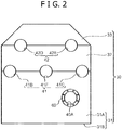
Fig. 2] Fig. 2 is a side view showing a housing of the compressor shown inFig. 1 . - [
Fig. 3] Fig. 3 is a sectional view showing an insertion bearing portion. - [
Fig. 4] Fig. 4 is an enlarged view showing the insertion bearing portion. - [
Fig. 5] Fig. 5 is a view schematically showing a range of displacement of a shaft to be adjusted by an adjusting portion. - [
Fig. 6] Fig. 6 is a view showing a state where an input shaft, a first shaft, a second shaft, and a third shaft are installed in a first housing element. - [
Fig. 7] Fig. 7 is a view showing a state where a fourth shaft and a fifth shaft are installed in a second housing element. - A compressor according to an embodiment of the present invention will be described with reference to
Figs. 1 to 7 . - As shown in
Fig. 1 , the compressor includes amotor 10 having anoutput shaft 12, a plurality ofshafts 20 each having agear 21, ahousing 30, and a plurality ofimpeller portions 50. In the embodiment, carbon dioxide gas is compressed by theimpeller portions 50. - The
shafts 20 includes five shafts (afirst shaft 20A to afifth shaft 20E) and aninput shaft 20F, shown inFig. 7 . - The
first shaft 20A has afirst pinion gear 21A as thegear 21. Thesecond shaft 20B has asecond pinion gear 21B as thegear 21. Thethird shaft 20C has athird pinion gear 21C as thegear 21. Thefourth shaft 20D has afourth pinion gear 21D as thegear 21. Thefifth shaft 20E has afifth pinion gear 21E as thegear 21. - The
input shaft 20F has abull gear 21F as thegear 21. The number of teeth (pitch diameter) of thebull gear 21F is set to be larger than the number of teeth (pitch diameter) of each of thepinion gears 21A to 21E. Theoutput shaft 12 of themotor 10 is connected to theinput shaft 20F via acoupling 14. Theoutput shaft 12 may be, however, connected to one of the other shafts instead of theinput shaft 20F. - The
housing 30 places thegears 21 and supports theshafts 20 such that at least one ends of each of theshafts 20 are exposed. As shown inFig. 2 , thehousing 30 includes afirst housing element 31, asecond housing element 32, and athird housing element 33. InFig. 2 , theshafts 20 are not shown. - The
first housing element 31 includes a squaretubular side wall 31A and abottom wall 31B covering an opening at a bottom of theside wall 31A. A first upper endsurface supporting section 41 is formed on an upper end surface of thefirst housing element 31 so as to support some of theshafts 20. Specifically, the first upper endsurface supporting section 41 includes a secondshaft supporting portion 41B supporting thesecond shaft 20B, a thirdshaft supporting portion 41C supporting thethird shaft 20C, and an inputshaft supporting portion 41F supporting theinput shaft 20F. The secondshaft supporting portion 41B, the inputshaft supporting portion 41F, and the thirdshaft supporting portion 41C are arranged side-by-side in this order. As shown inFigs. 6 and7 , the secondshaft supporting portion 41B is formed in such a position that allows thesecond shaft 20B to be supported by the secondshaft supporting portion 41B such that thesecond pinion gear 21B is engaged with thebull gear 21F. The thirdshaft supporting portion 41C is formed in such a position that allows thethird shaft 20C to be supported by the thirdshaft supporting portion 41C such that thethird pinion gear 21C is engaged with thebull gear 21F. The supportingportions side wall 31A other than the supportingportions portions - The
first housing element 31 has aninsertion support portion 40A supporting thefirst shaft 20A. As shown inFig. 2 , theinsertion support portion 40A is provided in a portion of thefirst housing element 31, and the portion is located below a position in height of the first upper endsurface supporting section 41. Specifically, as shown inFigs. 6 and7 , theinsertion support portion 40A is formed in such a position that allows thefirst shaft 20A to be supported by theinsertion support portion 40A such that thefirst pinion gear 21A is engaged with thebull gear 21F. Theinsertion support portion 40A has a shape that enables thefirst pinion gear 21A to be inserted into theinsertion support portion 40A and enables thefirst shaft 20A to be supported by theinsertion support portion 40A. - The
second housing element 32 is connectable to thefirst housing element 31 from above and is separable from thefirst housing element 31. Thesecond housing element 32 is formed into a square tube. A portion of a lower end surface of thesecond housing element 32, which is opposite the first upper endsurface supporting section 41 in the up and down direction, is formed into a semicircular arc that is recessed upwardly from the remaining portion of the lower end surface of thesecond housing element 32. - A second upper end
surface supporting section 42 is formed on an upper end surface of thesecond housing element 32 so as to support some of theshafts 20. Specifically, the second upper endsurface supporting section 42 includes a fourthshaft supporting portion 42D supporting thefourth shaft 20D, and a fifthshaft supporting portion 42E supporting thefifth shaft 20E. As shown inFig. 7 , the fourthshaft supporting portion 42D is formed in such a position that allows thefourth shaft 20D to be supported by the fourthshaft supporting portion 42D such that thefourth pinion gear 21D is engaged with thebull gear 21F. The fifthshaft supporting portion 42E is formed in such a position that allows thefifth shaft 20E to be supported by the fifthshaft supporting portion 42E such that thefifth pinion gear 21E is engaged with thebull gear 21F. The supportingportions second housing element 32 other than the supportingportions portions - The
third housing element 33 is connectable to thesecond housing element 32 from above and separable from thesecond housing element 32. Thethird housing element 33 is formed into a square tube. A portion of a lower end surface of thehousing element 33, which is opposite the second upper endsurface supporting section 42 in the up and down direction, is formed into a semicircular arc recessed upwardly from the remaining portion of the lower end surface of thethird housing element 33. - The
impeller portions 50 each are fixed to at least one end of the opposite ends of each of thefirst shaft 20A to thefifth shaft 20E. Accordingly, when therespective impeller portions 50 are fixed to the opposite ends of each of theshafts 20A to 20E, ten-stage compression becomes possible. Theimpeller portions 50 are covered by a casing (not shown), and theimpeller portions 50 compress gas (in the embodiment, carbon dioxide) within the casing. For example, as shown inFig. 1 , the gas compressed by animpeller portion 50B fixed to one end of thesecond shaft 20B is cooled by a cooler 15, and is subsequently further compressed by animpeller portion 50B fixed to the other end of thesecond shaft 20B. After that, the gas compressed by animpeller portion 50C fixed to one end of thethird shaft 20C is cooled by a cooler 16, and is subsequently further compressed by animpeller portion 50C fixed to the other end of thethird shaft 20C. The gas is also compressed by theimpeller portions 50 fixed to each of thefirst shaft 20A, thefourth shaft 20D, and thefifth shaft 20E, and is appropriately cooled by a cooler provided along a flow passage between the impeller portions. - In the embodiment, each of the
shafts 20A to 20F are received by a bearingportion 70 provided in a bearinghousing 60. InFig. 1 , the bearinghousings 60 and the bearingportions 70 are not shown.Fig. 2 shows only the bearinghousing 60 that holds the bearingportion 70 receiving thefirst shaft 20A. The bearinghousings 60 and the bearingportions 70 will be described below with reference to theFigs. 3 and4 .Fig. 3 shows the bearingportion 70 receiving thefirst shaft 20A, and the bearinghousing 60 holding this bearingportion 70. - The bearing
housing 60 is formed into a ring. As shown inFig. 3 , the bearinghousing 60 is fixed to thefirst housing element 31 by fixingtools 62 such as bolts. Specifically, thefirst housing element 31 has a circular through hole (insertion support portion 40A) in which the bearinghousing 60 is fitted. The bearinghousing 60 is fixed to a side surface of thefirst housing element 31 by thefixing tools 62 with the bearinghousing 60 fitted in the through hole. The through hole is set to have a diameter larger than a tip diameter of thefirst pinion gear 21A. - The bearing
portion 70 includes aninner ring 81, rolling elements (not shown), anouter ring 82, and a preventingportion 83. In the embodiment, the bearingportion 70 is an eccentric bearing. The bearingportion 70 is, however, limited to the eccentric bearing. InFig. 4 , theinner ring 81 and theouter ring 82 are not shown. - The preventing
portion 83 is fixed to an outer periphery of theouter ring 82 and prevents the rotation of theouter ring 82 relative to the bearinghousing 60. Specifically, the bearinghousing 60 includes a receivingportion 60a receiving the preventingportion 83, and the preventingportion 83 is disposed within the receivingportion 60a. More specifically, the receivingportion 60a includes acontact portion 60b that is in contact with the preventingportion 83 in a circumferential direction of theouter ring 82. The preventingportion 83 is in contact with thecontact portion 60b, thereby preventing the rotation of theouter ring 82 relative to the bearinghousing 60 or thefirst housing element 31. The receivingportion 60a has a shape recessed radially outward of the bearinghousing 60 from an inner periphery of the bearinghousing 60. The receivingportion 60a also has a shape that is open in a direction parallel to the central axis of thefirst shaft 20A (in a thickness direction of the bearing housing 60). Thecontact portion 60b is formed into a plane that is parallel to thefirst housing element 31 other than the first upper endsurface supporting section 41. In the embodiment, the preventingportion 83 includes a protrudedportion 84 and an adjustingportion 85. - The protruded
portion 84 has a shape protruded outwardly of theouter ring 82 from the outer periphery of theouter ring 82. The protrudedportion 84 has a female screw portion. - The adjusting
portion 85 is a member that allows the position of the protrudedportion 84 relative to thecontact portion 60b to be adjusted with the adjustingportion 85 in contact with thecontact portion 60b. The adjustingportion 85 has a male screw portion that is in engagement with the female screw portion with the adjustingportion 85 in contact with thecontact portion 60b. The male screw portion is configured such that the male screw portion is rotated relative to the female screw portion, thereby displacing the protrudedportion 84 between a first position and a second position. The first position is a position where a dimension between the protrudedportion 84 and thecontact portion 60b is a first dimension. The second position is a position where a dimension between the protrudedportion 84 and thecontact portion 60b is a second dimension larger than the first dimension. The male screw portion is rotated relative to the female screw portion, thereby displacing the position of the protrudedportion 84 relative to thecontact portion 60b. As a result, the position of theouter ring 82 relative to thefirst housing element 31 is displaced. In other words, the male screw portion is rotated relative to the female screw portion, thereby displacing the position of a central axis O of thefirst shaft 20A, as shown inFig. 6 . Accordingly, the engagement between thefirst pinion gear 21A and thebull gear 21F is adjusted. - In the embodiment, the preventing
portions 83 of the bearingportions 70 receiving thesecond shaft 20B to thefifth shaft 20E have the same configuration (adjusting function) as the preventingportion 83 of the bearingportion 70 receiving thefirst shaft 20A. Meanwhile, the preventingportion 83 of the bearingportion 70 receiving theinput shaft 20F has no adjusting function. The bearingportions 70 receiving thesecond shaft 20B to thefifth shaft 20E and theinput shaft 20F, and the bearinghousings 60 holding these bearingportions 70 each are formed divisible into two in the up and down direction. - A process for assembling the compressor according to the embodiment will be described next with reference to
Figs. 6 and7 . - First, the
first shaft 20A is inserted into theinsertion support portion 40A of thefirst housing element 33, and then, the bearingportion 70 and the bearinghousing 60 are installed. Specifically, one end of thefirst shaft 20A is inserted into theinsertion support portion 40A such that thefirst pinion gear 21A reaches the inside of thefirst housing element 31 through theinsertion support portion 40A from the outside of thefirst housing element 31. Then, the bearinghousing 60 is fixed to thefirst housing element 31 with the bearingportion 70 and the bearinghousing 60 located around the other end of thefirst shaft 20A. - Next, three shafts, that is, the
input shaft 20F, thesecond shaft 20B, and thethird shaft 20C, are placed on the first upper endsurface supporting section 41. At this time, respective lower parts (not shown) of the bearinghousings 60 and respective lower parts (not shown) of the bearingportions 70 are first placed on the secondshaft supporting portion 41B, the thirdshaft supporting portion 41C, and the inputshaft supporting portion 41F. Then, theshafts portions housings 60 and upper parts of (not shown) the bearingportions 70 are, respectively, connected to the lower parts from above the secondshaft supporting portion 41B, the thirdshaft supporting portion 41C, and the inputshaft supporting portion 41F. After that, thesecond housing element 32 is connected to thefirst housing element 31 from above. The upper parts and thesecond housing element 32 may be simultaneously connected to thefirst housing element 31. - Subsequently, as shown in
Fig. 7 , the two shafts, that is, thefourth shaft 20D and thefifth shaft 20E, are placed on the second upper endsurface supporting section 42. The process for placing theses shafts is the same as that for placing threeshafts surface supporting section 41. Lastly, the upper parts of the bearinghousing 60, those of the bearingportions 70, and thethird housing element 33 are connected to thesecond housing element 32 from above. - The installation of the
first shaft 20A in thefirst housing element 31 may be performed after the connection of thethird housing element 33 to thesecond housing element 32. Furthermore, at any time after theinput shaft 20F is supported by the inputshaft supporting portion 41F, theoutput shaft 12 of themotor 10 is connected to theinput shaft 20F. - As needed, the engagement between the
bull gear 21F and each of the pinion gears 21A to 21E is adjusted by the corresponding adjustingportion 85. - As described above, in the compressor according to the embodiment, the
housing 30 has theinsertion support portion 40A at the position in height different from the position in height of the first upper endsurface supporting section 41, and theinsertion support portion 40A allows thefirst pinion gear 21A to be inserted thereinto. Therefore, it is possible to increase the number of compression stages while preventing the significant increase in size of thehousing 30 in the direction orthogonal to the central axes of theshafts surface supporting section 41, the complicated installation of the shafts in thehousing 30, and the occurrence of the poor engagement between the gears. Specifically, theinsertion support portion 40A has a shape that enables thefirst pinion gear 21A to be inserted into theinsertion support portion 40A and enables thefirst shaft 20A to be supported by theinsertion support portion 40A. Accordingly, thefirst shaft 20A is inserted into theinsertion support portion 40A such that thefirst pinion gear 21A reaches the inside of thehousing 30 through theinsertion support portion 40A from the outside of thehousing 30. Thus, thefirst shaft 20A is installed in thehousing 30. Therefore, it is possible to easily install an additional shaft in the housing 30 (increase the number of compression stages) without increasing the number of divisions of thehousing 30, in other words, while preventing the occurrence of the poor engagement between thegears housing 30. - In addition, in the embodiment, the first upper end
surface supporting section 41 includes the inputshaft supporting portion 41F that supports theinput shaft 20F having thebull gear 21F. Theoutput shaft 12 of themotor 10 is connected to theinput shaft 20F. Therefore, the gears can serve as step-up gears, and the complicated installation of theinput shaft 20F, which has thebull gear 21F having the large number of teeth (pitch diameter) in thehousing 30, can be prevented. - Furthermore, in the embodiment, the
housing 30 includes thethird housing element 33. The second upper endsurface supporting section 42 is formed on the upper end surface of thesecond housing element 32. Theinsertion support portion 40A is formed a portion of thefirst housing element 31, and the portion is located below the first upper endsurface supporting section 41. Therefore, it is possible to effectively increase the number of compression stages (the number of shafts) while preventing the significant increase in size of thehousing 30. Specifically, theshafts 20B to 20F are supported by the first upper endsurface supporting section 41 and the second upper endsurface supporting section 42 located above the first upper endsurface supporting section 41, and thus, theinsertion support portion 40A is formed below the first upper endsurface supporting section 41. Therefore, thegears 21A to 21F can be effectively disposed in a space within thehousing 30. - In the embodiment, the
housing 30 also can support the fiveshafts 20A to 20E. Therefore, when the opposite ends of each of the five shafts are fixed to therespective impeller portions 50, up to ten-stage compression becomes possible. - In addition, in the embodiment, the preventing
portion 83 includes the protrudedportion 84 and the adjustingportion 85. In other words, the preventingportion 83 has both a function of preventing the rotation of theouter ring 82 relative to the bearinghousing 60 and a function of adjusting the positions of the central axes of the shafts (the engagement between thebull gear 21F and each of the pinion gears 21A to 21E), thereby simplifying the configuration. Specifically, the adjustingportion 85 is in contact with thecontact portion 60b, thereby preventing the rotation of theouter ring 82 relative to the bearinghousing 60. In addition, the position of the protrudedportion 84 relative to thecontact portion 60b is displaced, thereby displacing the positions of the bearingportion 70 and the central axis of the shaft supported by this bearingportion 70 relative to the bearing housing 60 (housing 30). Therefore, the engagement between the gears is adjusted. - Specifically, in the embodiment, the protruded
portion 84 has the female screw portion, and the adjustingportion 85 has the male screw portion that is in engagement with the female screw portion with the adjustingportion 85 in contact with thecontact portion 60b. Therefore, only rotating the adjustingportion 85, which has the male screw portion, relative to the protrudedportion 84, which has the female screw portion, enables adjustment of the engagement between the gears. - Furthermore, in the embodiment, the receiving
portion 60a has a shape that is open in the direction parallel to the central axes of theshafts 20A to 20E. Accordingly, the adjustingportion 85 provided within the receivingportion 60a can be adjusted from the side of the bearinghousing 60, thereby facilitating adjustment of the central positions of theshafts 20A to 20E. - The embodiment according to the present invention is described above. It should be considered that the embodiment disclosed herein is exemplary in all respects, and are not limitative. The scope of the present invention is not represented by the above description but by the scope of claims, and it is intended that connotation equivalent to the scope of claims, and all changes within the scope are included.
- For example, the
insertion support portion 40A may be formed in thesecond housing element 32 or thethird housing element 33. In addition, the number ofinsertion support portions 40A is not limited to one. For example, inFig. 2 , an additional insertion support portion may be formed in a portion of thefirst housing element 31, and the portion is located leftward of the portion where theinsertion support portion 40A is formed. - The number of shafts each having a pinion gear is limited to five.
- The
second housing element 32 and thethird housing element 33 may be not formed divisible but formed integrally. In this case, the fourthshaft supporting portion 42D and the fifthshaft supporting portion 42E each may have the same configuration as theinsertion support portion 40A. - The bearing
housings 60 and the bearingportions 70 which are placed on the first upper endsurface supporting section 41 are each limited to be formed divisible in the up and down direction. In addition, the bearinghousings 60 and the bearingportions 70 which are placed on the second upper endsurface supporting section 42 are each limited to be formed divisible in the up and down direction. - The
impeller portions 50 fixed to thefirst shaft 20A may be used as expanding portions, and theimpeller portions 50 connected to thesecond shaft 20B to thefifth shaft 20E may be used as compressing portions. - The compressor according to the above embodiment will be outlined now.
- The compressor according to the embodiment includes: a motor having an output shaft; a plurality of shafts each having a gear; a housing placing the gears and supporting the shafts such that opposite ends of each of the shafts are exposed; and a plurality of impeller portions each fixed to at least one end of the opposite ends of each of the shafts. The housing includes a first housing element and a second housing element connectable to the first housing element from above and separable from the first housing element. A first upper end surface supporting section is formed on an upper end surface of the first housing element, the first upper end surface supporting section supporting some of the shafts. The housing has at least one insertion support portion at a position in height different from a position in height of the first upper end surface supporting section, the at least one insertion support portion having a shape that enables the gear to be inserted into the at least one insertion support portion and enables the shaft to be supported by the at least one insertion support portion.
- In the compressor according to the embodiment, the housing has the insertion support portion at the position in height different from the position in height of the first upper end surface supporting section, and the insertion support portion allows the gear to be inserted thereinto. Therefore, it is possible to increase the number of compression stages while preventing the significant increase in size of the housing in the direction orthogonal to the central axes of the shafts supported by the first upper end surface supporting section, the complicated installation of the shafts in the housing, and the occurrence of the poor engagement between the gears. Specifically, the insertion support portion has a shape that enables the gear to be inserted into the insertion support portion and enables the shaft to be supported by the insertion support portion. Accordingly, the shaft is inserted into the insertion support portion such that the gear reaches the inside of the housing through the insertion support portion from the outside of the housing. Thus, the shaft is installed in the housing. Therefore, it is possible to easily install an additional shaft in the housing (increase the number of compression stages) without increasing the number of divisions of the housing, in other words, while preventing the occurrence of the poor engagement between the gears due to accumulation of the tolerance generated in assembling the housing.
- In the above compressor, the shafts may include an input shaft having a bull gear as the gear, the bull gear having the number of teeth that is larger than the number of teeth of each of the other gears. The first upper end surface supporting section may include an input shaft supporting portion that supports the input shaft such that the bull gear is engaged with each of the gears other than the bull gear. The output shaft of the motor may be connected to the input shaft.
- Accordingly, the gears can serve as step-up gears, and the complicated installation of the input shaft, which has the bull gear having the large number of teeth (pitch diameter), in the housing can be prevented.
- In the above compressor, the housing may further include a third housing element connectable to the second housing element from above and separable from the second housing element. A second upper end surface supporting section may be formed on an upper end surface of the second housing element, the second upper end surface supporting section supporting some of the shafts other than the input shaft. The at least one insertion support portion may be formed in a portion of the first housing element, the portion located below the first upper end surface supporting section.
- Accordingly, it is possible to effectively increase the number of compression stages (shafts) while preventing the significant increase in size of the housing. Specifically, the shafts are supported by the first upper end surface supporting section and the second upper end surface supporting section located above the first upper end surface supporting section, and thus, the insertion support portion is formed below the first upper end surface supporting section. Therefore, the gears can be effectively disposed in a space within the housing.
- Specifically, the shafts may include: a first shaft having a first pinion gear as the gear, the first pinion gear having the number of teeth that is smaller than the number of teeth of the bull gear; a second shaft having a second pinion gear as the gear, the second pinion gear having the number of teeth that is smaller than the number of teeth of the bull gear; a third shaft having a third pinion gear as the gear, the third pinion gear having the number of teeth that is smaller than the number of teeth of the bull gear; a fourth shaft having a fourth pinion gear as the gear, the fourth pinion gear having the number of teeth that is smaller than the number of teeth of the bull gear; and a fifth shaft having a fifth pinion gear as the gear, the fifth pinion gear having the number of teeth that is smaller than the number of teeth of the bull gear. The at least one insertion support portion may be formed in such a position that allows the first shaft to be supported by the at least one insertion support portion such that the first pinion gear is engaged with the bull gear. The first upper end surface supporting section may further include a second shaft supporting portion that supports the second shaft such that the second pinion gear is engaged with the bull gear, and a third shaft supporting portion that supports the third shaft such that the third pinion gear is engaged with the bull gear. The second upper end surface supporting section may include a fourth shaft supporting portion that supports the fourth shaft such that the fourth pinion gear is engaged with the bull gear, and a fifth shaft supporting portion that supports the fifth shaft such that the fifth pinion gear is engaged with the bull gear.
- Accordingly, when the opposite ends of each of the five shafts, that is, the first shaft to the fifth shaft are fixed to the respective impeller portions, up to ten-stage compression becomes possible.
- The compressor may further include a bearing housing fixed in the at least one insertion support portion, and a bearing portion receiving the shaft within the bearing housing. The bearing portion may be an eccentric bearing. The bearing portion may include an inner ring, an outer ring, and a preventing portion fixed to an outer periphery of the outer ring, the preventing portion preventing rotation of the outer ring relative to the bearing housing. The bearing housing may include a contact portion being in contact with the preventing portion in a circumferential direction of the outer ring, and a receiving portion that receives at least a portion of the preventing portion. The preventing portion may have a protruded portion that is protruded outwardly of the outer ring from the outer periphery of the outer ring, and an adjusting portion that enables a position of the protruded portion relative to the contact portion to be adjusted with the adjusting portion in contact with the contact portion.
- Accordingly, the preventing portion has both a function of preventing the rotation of the outer ring relative to the bearing housing and a function of adjusting the positions of the central axes of the shafts (the engagement between the gears), thereby simplifying the configuration. Specifically, the adjusting portion is in contact with the contact portion, thereby preventing the rotation of the outer ring relative to the bearing housing. In addition, the position of the protruded portion relative to the contact portion is displaced, thereby displacing the positions of the bearing portion and the central axis of the shaft supported by this bearing portion relative to the bearing housing (housing). Thus, the engagement between the gears is adjusted.
- Specifically, the protruded portion may have a female screw portion. The adjusting portion may have a male screw portion that is in engagement with the female screw portion with the adjusting portion in contact with the contact portion. The male screw portion may be configured such that the male screw portion is rotated relative to the female screw portion to displace the protruded portion between a first position where a dimension between the protruded portion and the contact portion is a first dimension and a second position where the dimension between the protruded portion and the contact portion is a second dimension larger than the first dimension.
- Accordingly, only rotating the adjusting portion, which has the male screw portion, relative to the protruded portion, which has the female screw portion, enables adjustment of the engagement between the gears.
- In the compressor, the receiving portion may have a shape that is open in a direction parallel to central axes of the shafts.
- Accordingly, the adjusting portion provided within the receiving portion can be adjusted from the side of the bearing housing, thereby facilitating the adjustment of the central position of the shaft.
- In the compressor, the impeller portions may be used as compression portions that compress gas, or some of the impeller portions that are fixed to the shafts supported by the first upper end surface supporting section may be used as compressing portions, and at least one of the impeller portions that is fixed to the shaft supported by the at least one insertion support portion may be used as an expanding portion that expands gas.
Claims (8)
- A compressor, comprising:a motor having an output shaft;a plurality of shafts each having a gear;a housing placing the gears and supporting the shafts such that opposite ends of each of the shafts are exposed; anda plurality of impeller portions each fixed to at least one end of the opposite ends of each of the shafts, whereinthe housing includes a first housing element and a second housing element connectable to the first housing element from above and separable from the first housing element,a first upper end surface supporting section is formed on an upper end surface of the first housing element, the first upper end surface supporting section supporting some of the shafts, andthe housing has at least one insertion support portion at a position in height different from a position in height of the first upper end surface supporting section, the at least one insertion support portion having a shape that enables the gear to be inserted into the at least one insertion support portion and enables the shaft to be supported by the at least one insertion support portion.
- The compressor according to claim 1, wherein
the shafts includes an input shaft having a bull gear as the gear, the bull gear having the number of teeth that is larger than the number of teeth of each of the other gears,
the first upper end surface supporting section includes an input shaft supporting portion that supports the input shaft such that the bull gear is engaged with each of the gears other than the bull gear, and
the output shaft of the motor is connected to the input shaft. - The compressor according to claim 2, wherein
the housing further includes a third housing element connectable to the second housing element from above and separable from the second housing element,
a second upper end surface supporting section is formed on an upper end surface of the second housing element, the second upper end surface supporting section supporting some of the shafts other than the input shaft, and
the at least one insertion support portion is formed in a portion of the first housing element, the portion located below the first upper end surface supporting section. - The compressor according to claim 3, wherein
the shafts includes: a first shaft having a first pinion gear as the gear, the first pinion gear having the number of teeth that is smaller than the number of teeth of the bull gear; a second shaft having a second pinion gear as the gear, the second pinion gear having the number of teeth that is smaller than the number of teeth of the bull gear; a third shaft having a third pinion gear as the gear, the third pinion gear having the number of teeth that is smaller than the number of teeth of the bull gear; a fourth shaft having a fourth pinion gear as the gear, the fourth pinion gear having the number of teeth that is smaller than the number of teeth of the bull gear; and a fifth shaft having a fifth pinion gear as the gear, the fifth pinion gear having the number of teeth that is smaller than the number of teeth of the bull gear,
the at least one insertion support portion is formed in such a position that allows the first shaft to be supported by the at least one insertion support portion such that the first pinion gear is engaged with the bull gear,
the first upper end surface supporting section further includes a second shaft supporting portion that supports the second shaft such that the second pinion gear is engaged with the bull gear, and a third shaft supporting portion that supports the third shaft such that the third pinion gear is engaged with the bull gear, and
the second upper end surface supporting section includes a fourth shaft supporting portion that supports the fourth shaft such that the fourth pinion gear is engaged with the bull gear, and a fifth shaft supporting portion that supports the fifth shaft such that the fifth pinion gear is engaged with the bull gear. - The compressor according to any one of clams 1 to 4, further comprising
a bearing housing fixed in the at least one insertion support portion, and
a bearing portion receiving the shaft within the bearing housing, wherein
the bearing portion is an eccentric bearing,
the bearing portion includes an inner ring, an outer ring, and a preventing portion fixed to an outer periphery of the outer ring, the preventing portion preventing rotation of the outer ring relative to the bearing housing,
the bearing housing includes a contact portion being in contact with the preventing portion in a circumferential direction of the outer ring, and a receiving portion that receives at least a portion of the preventing portion, and
the preventing portion has a protruded portion that is protruded outwardly of the outer ring from the outer periphery of the outer ring, and an adjusting portion that enables a position of the protruded portion relative to the contact portion to be adjusted with the adjusting portion in contact with the contact portion. - The compressor according to claim 5,
the protruded portion has a female screw portion,
the adjusting portion has a male screw portion that is in engagement with the female screw portion with the adjusting portion in contact with the contact portion, and
the male screw portion is configured such that the male screw portion is rotated relative to the female screw portion to displace the protruded portion between a first position where a dimension between the protruded portion and the contact portion is a first dimension and a second position where the dimension between the protruded portion and the contact portion is a second dimension larger than the first dimension. - The compressor according to claim 5, wherein
the receiving portion has a shape that is open in a direction parallel to central axes of the shafts. - The compressor according to claim 1, wherein
the impeller portions are used as compression portions that compress gas, or
some of the impeller portions that are fixed to the shafts supported by the first upper end surface supporting section are used as compressing portions, and at least one of the impeller portions that is fixed to the shaft supported by the at least one insertion support portion is used as an expanding portion that expands gas.
Applications Claiming Priority (2)
| Application Number | Priority Date | Filing Date | Title |
|---|---|---|---|
| JP2015172518A JP6395683B2 (en) | 2015-09-02 | 2015-09-02 | Compressor |
| PCT/JP2016/075597 WO2017038912A1 (en) | 2015-09-02 | 2016-09-01 | Compressor |
Publications (2)
| Publication Number | Publication Date |
|---|---|
| EP3346135A1 true EP3346135A1 (en) | 2018-07-11 |
| EP3346135A4 EP3346135A4 (en) | 2019-04-17 |
Family
ID=58188902
Family Applications (1)
| Application Number | Title | Priority Date | Filing Date |
|---|---|---|---|
| EP16841941.4A Withdrawn EP3346135A4 (en) | 2015-09-02 | 2016-09-01 | COMPRESSOR |
Country Status (5)
| Country | Link |
|---|---|
| US (1) | US10641275B2 (en) |
| EP (1) | EP3346135A4 (en) |
| JP (1) | JP6395683B2 (en) |
| KR (1) | KR102057692B1 (en) |
| WO (1) | WO2017038912A1 (en) |
Families Citing this family (7)
| Publication number | Priority date | Publication date | Assignee | Title |
|---|---|---|---|---|
| JP6395683B2 (en) * | 2015-09-02 | 2018-09-26 | 株式会社神戸製鋼所 | Compressor |
| JP7103312B2 (en) * | 2018-07-12 | 2022-07-20 | 株式会社デンソー | Centrifugal blower |
| US11261954B2 (en) * | 2019-02-19 | 2022-03-01 | Mid-States Oilfield Machine LLC | Gearbox case with wear sleeve |
| JP7221727B2 (en) * | 2019-02-22 | 2023-02-14 | 三菱重工コンプレッサ株式会社 | Geared Compressor Phase Adjustment System, Geared Compressor Phase Adjustment Jig, and Geared Compressor Phase Adjustment Method |
| US11592026B2 (en) * | 2020-12-22 | 2023-02-28 | Goodrich Corporation | Fan aspirator |
| US11795976B2 (en) | 2021-12-29 | 2023-10-24 | Ingersoll-Rand Industrial U.S., Inc. | Systems and methods for integrally geared centrifugal compressor to maintain rotor concentricity with differing pinion gear tooth counts |
| EP4224015A1 (en) * | 2022-02-07 | 2023-08-09 | Siemens Energy Global GmbH & Co. KG | Hydrogen compressors |
Family Cites Families (22)
| Publication number | Priority date | Publication date | Assignee | Title |
|---|---|---|---|---|
| US3150533A (en) * | 1960-06-22 | 1964-09-29 | Wallgren August Gunn Ferdinand | Gearing |
| GB967091A (en) * | 1961-04-14 | 1964-08-19 | Borsig Ag | Improvements in or relating to three-stage radial-flow compressors |
| CH569895A5 (en) * | 1973-12-19 | 1975-11-28 | Maag Zahnraeder & Maschinen Ag | |
| JPS5815677Y2 (en) * | 1976-11-04 | 1983-03-30 | 石川島播磨重工業株式会社 | turbo compressor |
| DD158489A3 (en) * | 1981-02-25 | 1983-01-19 | Helmut Paulat | GEARBOX, ESPECIALLY FOR MULTIWAVE COMPRESSORS |
| US4473754A (en) * | 1982-07-26 | 1984-09-25 | Williams International Corporation | Waste heat power generation system |
| JPS61218793A (en) * | 1985-03-25 | 1986-09-29 | Ebara Corp | Centrifugal compressor |
| US4750861A (en) * | 1985-10-15 | 1988-06-14 | Cooper Industries | Compressor components support system |
| DE4003482A1 (en) * | 1990-02-06 | 1991-08-08 | Borsig Babcock Ag | GEARBOX TURBO COMPRESSOR |
| US5402631A (en) * | 1991-05-10 | 1995-04-04 | Praxair Technology, Inc. | Integration of combustor-turbine units and integral-gear pressure processors |
| DE4241141A1 (en) * | 1992-12-07 | 1994-06-09 | Bhs Voith Getriebetechnik Gmbh | Compressor system with a gear transmission engaged in the drive train between a drive unit and a compressor area of the system |
| JP3457828B2 (en) * | 1997-03-05 | 2003-10-20 | 三菱重工業株式会社 | Compressor and gas expander device |
| US7415878B2 (en) * | 2006-08-24 | 2008-08-26 | Honeywell International, Inc. | Ball bearing turbocharger balancer |
| JP4876868B2 (en) * | 2006-11-27 | 2012-02-15 | 株式会社Ihi | Turbo compressor |
| KR100873043B1 (en) * | 2007-03-30 | 2008-12-09 | 삼성테크윈 주식회사 | Gear case assembly |
| DE102009044959A1 (en) * | 2009-09-24 | 2011-03-31 | Man Turbo Ag | Multi-stage turbo-compressor i.e. eight to ten stage turbo-compressor, for use as radial transmission compressor, has compressor stages sealed using sealing arrangement against fluid entry to pinion sections of shafts that support wheel |
| CN103180570B (en) * | 2010-10-28 | 2015-09-30 | 博格华纳公司 | There is the rolling element bearing sleeve of end thrust damping and anti-rotating assembly |
| DE102011003525A1 (en) * | 2011-02-02 | 2012-08-02 | Siemens Aktiengesellschaft | Stepped parting line on a gearbox |
| JP5616866B2 (en) | 2011-09-13 | 2014-10-29 | 株式会社神戸製鋼所 | Turbo compressor |
| DE102014207283A1 (en) * | 2013-04-30 | 2014-10-30 | Voith Patent Gmbh | Pre-assembled gear shaft unit |
| DE102013210497A1 (en) * | 2013-06-06 | 2014-12-11 | Siemens Aktiengesellschaft | geared compressors |
| JP6395683B2 (en) * | 2015-09-02 | 2018-09-26 | 株式会社神戸製鋼所 | Compressor |
-
2015
- 2015-09-02 JP JP2015172518A patent/JP6395683B2/en active Active
-
2016
- 2016-09-01 WO PCT/JP2016/075597 patent/WO2017038912A1/en not_active Ceased
- 2016-09-01 KR KR1020187005556A patent/KR102057692B1/en not_active Expired - Fee Related
- 2016-09-01 US US15/754,610 patent/US10641275B2/en active Active
- 2016-09-01 EP EP16841941.4A patent/EP3346135A4/en not_active Withdrawn
Also Published As
| Publication number | Publication date |
|---|---|
| WO2017038912A1 (en) | 2017-03-09 |
| JP6395683B2 (en) | 2018-09-26 |
| JP2017048719A (en) | 2017-03-09 |
| EP3346135A4 (en) | 2019-04-17 |
| KR102057692B1 (en) | 2019-12-19 |
| US20180283389A1 (en) | 2018-10-04 |
| US10641275B2 (en) | 2020-05-05 |
| KR20180034566A (en) | 2018-04-04 |
Similar Documents
| Publication | Publication Date | Title |
|---|---|---|
| EP3346135A1 (en) | Compressor | |
| CN103339383B (en) | The joining portion of the stepped shape on the driving mechanism housing of fluid machinery | |
| CN107148517B (en) | Separable housings and fluid machines for transmissions | |
| KR100872321B1 (en) | Method of manufacturing simple planetary gear apparatus and series of simple planetary gear apparatus | |
| EP2860402B1 (en) | Turbo machine | |
| US9657738B2 (en) | Scroll compressor | |
| CN105683584B (en) | The method for dismounting of the dismounting packing ring assemblies of stator blade segment and the stator blade segment using the component | |
| US20160348783A1 (en) | Shift range switching device for vehicle | |
| EP1882856A1 (en) | Complex dry vacuum pump having Roots and screw rotors | |
| EP2746605A2 (en) | Assembling method of bearing unit | |
| WO2013182492A1 (en) | High pressure ratio compressors with multiple intercooling and related methods | |
| EP4036415A1 (en) | Geared compressor and method of designing geared compressor | |
| EP3051131B1 (en) | Compressor and method for producing compressor | |
| CN104364474A (en) | Stator blade diaphragm ring, turbine and method | |
| EP3263905A1 (en) | Adaptor and vacuum pump | |
| RU2660731C1 (en) | Sealing component for step sewing seals of reducers housings | |
| US9546681B2 (en) | Crown shaped retainer | |
| US9869193B2 (en) | Sealing device between two axisymmetric coaxial parts | |
| JP2006009925A (en) | Planetary gear reducer of multiple stage type | |
| JP5789210B2 (en) | Centrifugal compressor assembly method and centrifugal compressor | |
| EP2685606B1 (en) | Motor's stator unit | |
| JP2014129859A (en) | Bearing device and compressor for turbo refrigerator | |
| EP4700255A1 (en) | Strain wave gear device | |
| KR20170039591A (en) | Inhibiter switch | |
| WO2014063207A1 (en) | Bearing shield and method for manufacturing a bearing shield |
Legal Events
| Date | Code | Title | Description |
|---|---|---|---|
| STAA | Information on the status of an ep patent application or granted ep patent |
Free format text: STATUS: THE INTERNATIONAL PUBLICATION HAS BEEN MADE |
|
| PUAI | Public reference made under article 153(3) epc to a published international application that has entered the european phase |
Free format text: ORIGINAL CODE: 0009012 |
|
| STAA | Information on the status of an ep patent application or granted ep patent |
Free format text: STATUS: REQUEST FOR EXAMINATION WAS MADE |
|
| 17P | Request for examination filed |
Effective date: 20180215 |
|
| AK | Designated contracting states |
Kind code of ref document: A1 Designated state(s): AL AT BE BG CH CY CZ DE DK EE ES FI FR GB GR HR HU IE IS IT LI LT LU LV MC MK MT NL NO PL PT RO RS SE SI SK SM TR |
|
| AX | Request for extension of the european patent |
Extension state: BA ME |
|
| DAV | Request for validation of the european patent (deleted) | ||
| DAX | Request for extension of the european patent (deleted) | ||
| A4 | Supplementary search report drawn up and despatched |
Effective date: 20190318 |
|
| RIC1 | Information provided on ipc code assigned before grant |
Ipc: F04D 25/16 20060101ALI20190312BHEP Ipc: F16H 1/22 20060101ALI20190312BHEP Ipc: F04D 29/053 20060101ALI20190312BHEP Ipc: F16H 57/02 20120101ALI20190312BHEP Ipc: F04D 29/056 20060101AFI20190312BHEP Ipc: F16H 57/022 20120101ALI20190312BHEP Ipc: F04D 29/42 20060101ALI20190312BHEP Ipc: F04D 17/12 20060101ALI20190312BHEP |
|
| STAA | Information on the status of an ep patent application or granted ep patent |
Free format text: STATUS: EXAMINATION IS IN PROGRESS |
|
| 17Q | First examination report despatched |
Effective date: 20201215 |
|
| REG | Reference to a national code |
Ref country code: DE Ref legal event code: R079 Free format text: PREVIOUS MAIN CLASS: F04D0029056000 Ipc: F04D0029620000 |
|
| RIC1 | Information provided on ipc code assigned before grant |
Ipc: F04D 29/62 20060101AFI20230424BHEP |
|
| GRAP | Despatch of communication of intention to grant a patent |
Free format text: ORIGINAL CODE: EPIDOSNIGR1 |
|
| STAA | Information on the status of an ep patent application or granted ep patent |
Free format text: STATUS: GRANT OF PATENT IS INTENDED |
|
| INTG | Intention to grant announced |
Effective date: 20230615 |
|
| STAA | Information on the status of an ep patent application or granted ep patent |
Free format text: STATUS: THE APPLICATION IS DEEMED TO BE WITHDRAWN |
|
| 18D | Application deemed to be withdrawn |
Effective date: 20231026 |