EP3346020A1 - Steel wire for springs, and spring - Google Patents
Steel wire for springs, and spring Download PDFInfo
- Publication number
- EP3346020A1 EP3346020A1 EP16842041.2A EP16842041A EP3346020A1 EP 3346020 A1 EP3346020 A1 EP 3346020A1 EP 16842041 A EP16842041 A EP 16842041A EP 3346020 A1 EP3346020 A1 EP 3346020A1
- Authority
- EP
- European Patent Office
- Prior art keywords
- steel wire
- spring
- iron
- spring steel
- content
- Prior art date
- Legal status (The legal status is an assumption and is not a legal conclusion. Google has not performed a legal analysis and makes no representation as to the accuracy of the status listed.)
- Granted
Links
Images
Classifications
-
- C—CHEMISTRY; METALLURGY
- C22—METALLURGY; FERROUS OR NON-FERROUS ALLOYS; TREATMENT OF ALLOYS OR NON-FERROUS METALS
- C22C—ALLOYS
- C22C38/00—Ferrous alloys, e.g. steel alloys
- C22C38/18—Ferrous alloys, e.g. steel alloys containing chromium
-
- C—CHEMISTRY; METALLURGY
- C21—METALLURGY OF IRON
- C21D—MODIFYING THE PHYSICAL STRUCTURE OF FERROUS METALS; GENERAL DEVICES FOR HEAT TREATMENT OF FERROUS OR NON-FERROUS METALS OR ALLOYS; MAKING METAL MALLEABLE, e.g. BY DECARBURISATION OR TEMPERING
- C21D1/00—General methods or devices for heat treatment, e.g. annealing, hardening, quenching or tempering
- C21D1/18—Hardening; Quenching with or without subsequent tempering
- C21D1/25—Hardening, combined with annealing between 300 degrees Celsius and 600 degrees Celsius, i.e. heat refining ("Vergüten")
-
- C—CHEMISTRY; METALLURGY
- C21—METALLURGY OF IRON
- C21D—MODIFYING THE PHYSICAL STRUCTURE OF FERROUS METALS; GENERAL DEVICES FOR HEAT TREATMENT OF FERROUS OR NON-FERROUS METALS OR ALLOYS; MAKING METAL MALLEABLE, e.g. BY DECARBURISATION OR TEMPERING
- C21D1/00—General methods or devices for heat treatment, e.g. annealing, hardening, quenching or tempering
- C21D1/34—Methods of heating
- C21D1/44—Methods of heating in heat-treatment baths
- C21D1/48—Metal baths
-
- C—CHEMISTRY; METALLURGY
- C21—METALLURGY OF IRON
- C21D—MODIFYING THE PHYSICAL STRUCTURE OF FERROUS METALS; GENERAL DEVICES FOR HEAT TREATMENT OF FERROUS OR NON-FERROUS METALS OR ALLOYS; MAKING METAL MALLEABLE, e.g. BY DECARBURISATION OR TEMPERING
- C21D6/00—Heat treatment of ferrous alloys
- C21D6/002—Heat treatment of ferrous alloys containing Cr
-
- C—CHEMISTRY; METALLURGY
- C21—METALLURGY OF IRON
- C21D—MODIFYING THE PHYSICAL STRUCTURE OF FERROUS METALS; GENERAL DEVICES FOR HEAT TREATMENT OF FERROUS OR NON-FERROUS METALS OR ALLOYS; MAKING METAL MALLEABLE, e.g. BY DECARBURISATION OR TEMPERING
- C21D6/00—Heat treatment of ferrous alloys
- C21D6/008—Heat treatment of ferrous alloys containing Si
-
- C—CHEMISTRY; METALLURGY
- C21—METALLURGY OF IRON
- C21D—MODIFYING THE PHYSICAL STRUCTURE OF FERROUS METALS; GENERAL DEVICES FOR HEAT TREATMENT OF FERROUS OR NON-FERROUS METALS OR ALLOYS; MAKING METAL MALLEABLE, e.g. BY DECARBURISATION OR TEMPERING
- C21D8/00—Modifying the physical properties of ferrous metals or ferrous alloys by deformation combined with, or followed by, heat treatment
- C21D8/06—Modifying the physical properties of ferrous metals or ferrous alloys by deformation combined with, or followed by, heat treatment during manufacturing of rods or wires
-
- C—CHEMISTRY; METALLURGY
- C21—METALLURGY OF IRON
- C21D—MODIFYING THE PHYSICAL STRUCTURE OF FERROUS METALS; GENERAL DEVICES FOR HEAT TREATMENT OF FERROUS OR NON-FERROUS METALS OR ALLOYS; MAKING METAL MALLEABLE, e.g. BY DECARBURISATION OR TEMPERING
- C21D9/00—Heat treatment, e.g. annealing, hardening, quenching or tempering, adapted for particular articles; Furnaces therefor
- C21D9/02—Heat treatment, e.g. annealing, hardening, quenching or tempering, adapted for particular articles; Furnaces therefor for springs
-
- C—CHEMISTRY; METALLURGY
- C21—METALLURGY OF IRON
- C21D—MODIFYING THE PHYSICAL STRUCTURE OF FERROUS METALS; GENERAL DEVICES FOR HEAT TREATMENT OF FERROUS OR NON-FERROUS METALS OR ALLOYS; MAKING METAL MALLEABLE, e.g. BY DECARBURISATION OR TEMPERING
- C21D9/00—Heat treatment, e.g. annealing, hardening, quenching or tempering, adapted for particular articles; Furnaces therefor
- C21D9/52—Heat treatment, e.g. annealing, hardening, quenching or tempering, adapted for particular articles; Furnaces therefor for wires; for strips ; for rods of unlimited length
- C21D9/525—Heat treatment, e.g. annealing, hardening, quenching or tempering, adapted for particular articles; Furnaces therefor for wires; for strips ; for rods of unlimited length for wire, for rods
-
- C—CHEMISTRY; METALLURGY
- C22—METALLURGY; FERROUS OR NON-FERROUS ALLOYS; TREATMENT OF ALLOYS OR NON-FERROUS METALS
- C22C—ALLOYS
- C22C38/00—Ferrous alloys, e.g. steel alloys
- C22C38/001—Ferrous alloys, e.g. steel alloys containing N
-
- C—CHEMISTRY; METALLURGY
- C22—METALLURGY; FERROUS OR NON-FERROUS ALLOYS; TREATMENT OF ALLOYS OR NON-FERROUS METALS
- C22C—ALLOYS
- C22C38/00—Ferrous alloys, e.g. steel alloys
- C22C38/002—Ferrous alloys, e.g. steel alloys containing In, Mg, or other elements not provided for in one single group C22C38/001 - C22C38/60
-
- C—CHEMISTRY; METALLURGY
- C22—METALLURGY; FERROUS OR NON-FERROUS ALLOYS; TREATMENT OF ALLOYS OR NON-FERROUS METALS
- C22C—ALLOYS
- C22C38/00—Ferrous alloys, e.g. steel alloys
- C22C38/02—Ferrous alloys, e.g. steel alloys containing silicon
-
- C—CHEMISTRY; METALLURGY
- C22—METALLURGY; FERROUS OR NON-FERROUS ALLOYS; TREATMENT OF ALLOYS OR NON-FERROUS METALS
- C22C—ALLOYS
- C22C38/00—Ferrous alloys, e.g. steel alloys
- C22C38/04—Ferrous alloys, e.g. steel alloys containing manganese
-
- C—CHEMISTRY; METALLURGY
- C22—METALLURGY; FERROUS OR NON-FERROUS ALLOYS; TREATMENT OF ALLOYS OR NON-FERROUS METALS
- C22C—ALLOYS
- C22C38/00—Ferrous alloys, e.g. steel alloys
- C22C38/06—Ferrous alloys, e.g. steel alloys containing aluminium
-
- C—CHEMISTRY; METALLURGY
- C22—METALLURGY; FERROUS OR NON-FERROUS ALLOYS; TREATMENT OF ALLOYS OR NON-FERROUS METALS
- C22C—ALLOYS
- C22C38/00—Ferrous alloys, e.g. steel alloys
- C22C38/18—Ferrous alloys, e.g. steel alloys containing chromium
- C22C38/20—Ferrous alloys, e.g. steel alloys containing chromium with copper
-
- C—CHEMISTRY; METALLURGY
- C22—METALLURGY; FERROUS OR NON-FERROUS ALLOYS; TREATMENT OF ALLOYS OR NON-FERROUS METALS
- C22C—ALLOYS
- C22C38/00—Ferrous alloys, e.g. steel alloys
- C22C38/18—Ferrous alloys, e.g. steel alloys containing chromium
- C22C38/22—Ferrous alloys, e.g. steel alloys containing chromium with molybdenum or tungsten
-
- C—CHEMISTRY; METALLURGY
- C22—METALLURGY; FERROUS OR NON-FERROUS ALLOYS; TREATMENT OF ALLOYS OR NON-FERROUS METALS
- C22C—ALLOYS
- C22C38/00—Ferrous alloys, e.g. steel alloys
- C22C38/18—Ferrous alloys, e.g. steel alloys containing chromium
- C22C38/24—Ferrous alloys, e.g. steel alloys containing chromium with vanadium
-
- C—CHEMISTRY; METALLURGY
- C22—METALLURGY; FERROUS OR NON-FERROUS ALLOYS; TREATMENT OF ALLOYS OR NON-FERROUS METALS
- C22C—ALLOYS
- C22C38/00—Ferrous alloys, e.g. steel alloys
- C22C38/18—Ferrous alloys, e.g. steel alloys containing chromium
- C22C38/26—Ferrous alloys, e.g. steel alloys containing chromium with niobium or tantalum
-
- C—CHEMISTRY; METALLURGY
- C22—METALLURGY; FERROUS OR NON-FERROUS ALLOYS; TREATMENT OF ALLOYS OR NON-FERROUS METALS
- C22C—ALLOYS
- C22C38/00—Ferrous alloys, e.g. steel alloys
- C22C38/18—Ferrous alloys, e.g. steel alloys containing chromium
- C22C38/28—Ferrous alloys, e.g. steel alloys containing chromium with titanium or zirconium
-
- C—CHEMISTRY; METALLURGY
- C22—METALLURGY; FERROUS OR NON-FERROUS ALLOYS; TREATMENT OF ALLOYS OR NON-FERROUS METALS
- C22C—ALLOYS
- C22C38/00—Ferrous alloys, e.g. steel alloys
- C22C38/18—Ferrous alloys, e.g. steel alloys containing chromium
- C22C38/32—Ferrous alloys, e.g. steel alloys containing chromium with boron
-
- C—CHEMISTRY; METALLURGY
- C22—METALLURGY; FERROUS OR NON-FERROUS ALLOYS; TREATMENT OF ALLOYS OR NON-FERROUS METALS
- C22C—ALLOYS
- C22C38/00—Ferrous alloys, e.g. steel alloys
- C22C38/18—Ferrous alloys, e.g. steel alloys containing chromium
- C22C38/34—Ferrous alloys, e.g. steel alloys containing chromium with more than 1.5% by weight of silicon
-
- C—CHEMISTRY; METALLURGY
- C22—METALLURGY; FERROUS OR NON-FERROUS ALLOYS; TREATMENT OF ALLOYS OR NON-FERROUS METALS
- C22C—ALLOYS
- C22C38/00—Ferrous alloys, e.g. steel alloys
- C22C38/60—Ferrous alloys, e.g. steel alloys containing lead, selenium, tellurium, or antimony, or more than 0.04% by weight of sulfur
-
- F—MECHANICAL ENGINEERING; LIGHTING; HEATING; WEAPONS; BLASTING
- F16—ENGINEERING ELEMENTS AND UNITS; GENERAL MEASURES FOR PRODUCING AND MAINTAINING EFFECTIVE FUNCTIONING OF MACHINES OR INSTALLATIONS; THERMAL INSULATION IN GENERAL
- F16F—SPRINGS; SHOCK-ABSORBERS; MEANS FOR DAMPING VIBRATION
- F16F1/00—Springs
- F16F1/02—Springs made of steel or other material having low internal friction; Wound, torsion, leaf, cup, ring or the like springs, the material of the spring not being relevant
-
- C—CHEMISTRY; METALLURGY
- C21—METALLURGY OF IRON
- C21D—MODIFYING THE PHYSICAL STRUCTURE OF FERROUS METALS; GENERAL DEVICES FOR HEAT TREATMENT OF FERROUS OR NON-FERROUS METALS OR ALLOYS; MAKING METAL MALLEABLE, e.g. BY DECARBURISATION OR TEMPERING
- C21D2211/00—Microstructure comprising significant phases
- C21D2211/004—Dispersions; Precipitations
-
- C—CHEMISTRY; METALLURGY
- C21—METALLURGY OF IRON
- C21D—MODIFYING THE PHYSICAL STRUCTURE OF FERROUS METALS; GENERAL DEVICES FOR HEAT TREATMENT OF FERROUS OR NON-FERROUS METALS OR ALLOYS; MAKING METAL MALLEABLE, e.g. BY DECARBURISATION OR TEMPERING
- C21D2211/00—Microstructure comprising significant phases
- C21D2211/008—Martensite
-
- C—CHEMISTRY; METALLURGY
- C21—METALLURGY OF IRON
- C21D—MODIFYING THE PHYSICAL STRUCTURE OF FERROUS METALS; GENERAL DEVICES FOR HEAT TREATMENT OF FERROUS OR NON-FERROUS METALS OR ALLOYS; MAKING METAL MALLEABLE, e.g. BY DECARBURISATION OR TEMPERING
- C21D9/00—Heat treatment, e.g. annealing, hardening, quenching or tempering, adapted for particular articles; Furnaces therefor
- C21D9/52—Heat treatment, e.g. annealing, hardening, quenching or tempering, adapted for particular articles; Furnaces therefor for wires; for strips ; for rods of unlimited length
Definitions
- the present invention relates to a spring steel wire used for high strength springs such as valve springs, clutch damper springs, and suspension springs which are mainly used for automobiles, and particularly relates to a high strength spring steel wire having excellent settling resistance after coiliing, and a spring including the steel wire.
- cold formed springs are mainly employed.
- the cold formed springs are manufactured by carrying out cold coiliing with high strength steel wires in which steel has been subjected to quenching and tempering in advance.
- the measure, in which tensile strength after quenching and tempering is enhanced is well known.
- Patent Documents 1 and 2 technologies of improving fatigue strength and settling resistance have been proposed.
- tensile strength of a steel wire is enhanced by containing a large amount of an alloying element as a chemical composition such as Si.
- an alloying element as a chemical composition such as Si.
- ductility and toughness are remarkably degraded such that coiliing cannot be carried out, or an obtained spring cannot bear use as a spring.
- Patent Document 3 proposes a technology of improving settling resistance of a spring by causing fine cementite of 100 nm or smaller to be dispersed in steel.
- Patent Document 3 in order to restrain this fine cementite from decomposing and dissipating during heat treatment, there is a need to cause Cr and V to be concentrated in the cementite such that the concentration of Cr and the concentration of V reach a predetermined concentration or higher.
- the fine cementite in which alloying elements such as Cr and V are concentrated has remarkably low ductility and toughness. Therefore, in the technology of Patent Document 3, there is concern that coiliing for obtaining a spring from a steel wire cannot be carried out, or an obtained spring cannot bear use as a spring.
- Patent Document 4 has proposed a technology of improving settling resistance of a suspension spring.
- steel mainly including a structure of martensite and bainite is subjected to cold working. Thereafter, quenching and tempering are performed. Then, prior austenite grains are refined, and undissolved carbide is reduced as much as possible.
- spring steel mainly including the structure of martensite and bainite.
- the structure of martensite and bainite in high carbon steel such as spring steel is brittle so that it is difficult to carry out cold working.
- Patent Documents 5 to 8 have also proposed technologies of improving fatigue properties or settling resistance by reducing the amount of undissolved carbide (cementite). However, in such technologies, the effect of improving fatigue properties or settling resistance is small.
- An object of the present invention is to provide a high strength spring steel wire which has favorable workability, in which the amount of plastic deformation is small even when being used under a high-stress load after coiliing, and which has excellent settling resistance to the extent of being able to sufficiently cope with recent demands for high strengthening, and a spring including the spring steel wire.
- the inventors Based on the knowledge described above as in (a) to (e), the inventors have found that settling resistance after coiliing can be reliably and sufficiently improved without impairing workability, when a structure of a steel wire includes, by area ratio, tempered martensite of 90% or more, when at the same time, the prior austenite grain size number is No. 12.5 or higher, and when furthermore, the presence density of iron-based carbide having an equivalent circle diameter ranging from 0.15 ⁇ m to 0.50 ⁇ m ranges from 0.40 pieces/ ⁇ m 2 to 2.00 pieces/ ⁇ m 2 , and have attained the present invention.
- the gist of the present invention is as follows.
- a spring steel wire according to an embodiment of the present invention (hereinafter, a spring steel wire according to the present embodiment) and a spring according to an embodiment of the present invention (hereinafter, according to a spring of the present embodiment) will be described.
- the lower limit is set to 0.40%, is preferably set to 0.45% or more, and is more preferably set to 0.50% or more. Since the alloying cost of C is low compared to other strengthening elements, if a large amount of C can be contained, high strength can be obtained at a low alloying cost. However, when C is excessively contained, the ductility and toughness are degraded so that the workability is remarkably degraded. Therefore, the upper limit for the C content is set to 0.75%. The C content is preferably set to 0.67% or less and is more preferably set to 0.65% or less.
- Si is an element having deoxidizing action.
- Si since Si is element which significantly suppresses softening of steel after heat treatment, Si is an element effective in improving settling resistance.
- the lower limit is set to 1.00%.
- the Si content is preferably set to 1.20% or more. Meanwhile, when Si is excessively contained, ductility and toughness of steel are degraded so that workability is remarkably degraded. Therefore, the upper limit for the Si content is set to 5.00%.
- the Si content is preferably set to 3.50% or less.
- Mn is an element which fixes S in steel as MnS and is effective in enhancing hardenability such that hardness after heat treatment is sufficiently improved.
- the Mn content is set to 0.20% or more, is preferably set to 0.25% or more, and is more preferably set to 0.30% or more.
- the Mn content is set to 2.00% or less.
- the Mn content is preferably set to 1.50% or less and is more preferably set to 1.20% or less.
- P is included in steel by 0.0001% or more as impurities. Therefore, the lower limit is set to 0.0001%.
- P is an element being segregated in prior austenite grain boundaries and the like, so that steel becomes prominently brittle and workability is remarkably degraded.
- the upper limit for the P content is set to 0.0500%.
- the P content is preferably 0.0300% or less, is more preferably set to 0.0200% or less, and is still more preferably set to 0.0150% or less.
- the lower limit for the S content is set to 0.0001%.
- S is an element causing steel to be brittle. Accordingly, it is desirable that the S content is reduced as much as possible. Particularly, when the S content exceeds 0.0500%, the adverse influence becomes prominent. Therefore, the upper limit for the S content is set to 0.0500%.
- the amount of S is preferably set to 0.0300% or less, is more preferably set to 0.0200% or less, and is still more preferably set to 0.0150% or less.
- the Cr content is set to 0.50% or more, is preferably set to 0.60% or more, and is more preferably set to 0.70% or more.
- Cr is solid-solubilized in iron-based carbide and stabilizes the carbide. Therefore, when there is an excessive amount of Cr, iron-based undissolved carbide increases more than necessary, so that strength after heat treatment is degraded. In this case, settling resistance is degraded, on the contrary. When there is an excessive amount of Cr, ductility is degraded, and the workability is remarkably degraded. From these viewpoint, the Cr content is set to 3.50% or less, is preferably set to 3.00% or less, and is more preferably set to 2.75% or less.
- Al is included in steel by 0.0005% or more as impurities. Therefore, the lower limit for the Al content is set to 0.0005%.
- Al is an element forming oxide such as Al 2 O 3 , such that ductility and toughness of steel are degraded and workability is remarkably degraded. Therefore, the Al content is set to 0.0500% or less. It is desirable that the Al content is reduced as much as possible.
- the Al content is preferably set to 0.0100% or less.
- N is an element which combines with Al, V, Ti, and/or Nb in steel and forms nitride.
- This nitride has an effect of refining prior austenite grains.
- the N content is set to 0.0020% or more and is preferably set to 0.0030% or more. Meanwhile, when there is an excessive amount of N, the nitride is coarsened. As a result, ductility of steel is degraded and workability is remarkably degraded. Therefore, the N content is set to 0.0100% or less and is preferably set to 0.0070% or less.
- the spring steel wire according to the present embodiment includes the elements described above, and the remainder includes Fe and impurities.
- all of Mo, V, W, Nb, Ti, Ca, Mg, Zr, B, Cu, and Ni are not necessarily contained, and their lower limits are 0%.
- Mo, V, W, Nb, and Ti are elements contributing to improvement of settling resistance by suppressing softening after heat treatment.
- the amounts of Mo, V, and W are preferably set to 0.01% or more.
- the amount of Nb is preferably set to 0.005% or more.
- the amount of Ti is preferably set to 0.001% or more.
- the upper limit for the Mo content is set to 2.00%
- the upper limit for the V content is set to 0.50%
- the upper limit for the W content is set to 0.50%
- the upper limit for the Nb content is set to 0.100%
- the upper limit for the Ti content is set to 0.100%. It is more preferable that the Mo content ranges from 0.05% to 0.60%
- the V content ranges from 0.05% to 0.35%
- the W content ranges from 0.05% to 0.35%
- the Nb content ranges from 0.005% to 0.050%
- the Ti content ranges from 0.010% to 0.080%.
- All of Ca, Mg, and Zr are elements having an effect of improving hardness of steel after heat treatment by forming oxide, becoming crystallized nuclei of MnS, causing the MnS to be finely dispersed in a uniform manner, and enhancing hardenability by means of the MnS.
- all of B, Cu, and Ni are elements having an effect of improving hardness after heat treatment by being solid-solubilized in steel and enhancing hardenability.
- the lower limits for the amounts of Ca and Mg are set to 0.0002%, the lower limit for the amount of Zr is set to 0.0005%, the lower limit for the amount of B is set to 0.0005%, the lower limit for the amount of Cu is set to 0.05%, and the lower limit for the amount of Ni is set to 0.05%. Meanwhile, if the Ca content and the Mg content exceed 0.0100% and if the Zr content exceeds 0.1000%, hard inclusions such as oxide, sulfide, and the like are excessively formed, so that ductility of steel is degraded and workability is remarkably degraded.
- the upper limits for the Ca content and the Mg content are set to 0.0100%, the upper limit for the Zr content is set to 0.1000%, the upper limit for the B content is set to 0.0100%, the upper limit for the Cu content is set to 1.00%, and the upper limit for the Ni content is set to 3.00%.
- the spring steel wire according to the present embodiment includes a chemical composition containing the essential elements and a remainder including Fe and impurities, or a chemical composition containing the optional elements described above in addition to the essential elements, and a remainder of Fe and impurities.
- impurities other than those described above O and the like are considered, and their amounts are preferably set to 0.05% or less in total.
- the structure of the spring steel wire is a structure having tempered martensite as a main constituent, excellent settling resistance can be obtained.
- phases other than the tempered martensite there are ferrite, pearlite, bainite, residual austenite, and the like.
- settling resistance is degraded.
- remainder structures are further reduced, settling resistance is further improved.
- the remainder structures are set to less than 10% by total area ratio. That is, the area ratio of the tempered martensite is regulated to 90% or higher.
- the residual shear strain amount that is an index value for settling resistance can be set to 0.029% or less by setting the area ratio of the tempered martensite to 90% or more and controlling the prior austenite grain size, the iron-based carbide size, and the distribution state, which will be described below.
- the area ratio of the tempered martensite may be 100%.
- the area ratio of the tempered martensite needs only to be 90% or more by average area ratio when a cross section (C-cross section) of a spring steel wire orthogonal to the length direction after quenching and tempering is observed and image analysis is performed.
- the area ratio of the tempered martensite may be represented by a value measured at a 1/4 position of a diameter D from a location on the outer circumferential surface of a steel wire in the C-cross section of the steel wire.
- the area ratio of martensite may be obtained by collecting a sample from a 1/4 portion of the diameter D from the outer circumferential surface in the C-cross section of the steel wire, performing etching using a nital etching solution, capturing five photographs of the structure of 1,000-fold using an optical microscope, and performing image analysis.
- the prior austenite grain size number is set to No. 12.5 or higher.
- the prior austenite grain size number is preferably set to No. 13.5 or higher, is more preferably set to No. 14.0 or higher, and is still more preferably set to No. 14.5 or higher. Since it is preferable for the prior austenite grain size to be small, there is no need to provide an upper limit for the grain size number.
- the prior austenite grain size number needs only to be measured by observing prior austenite grain boundaries which are revealed through etching using an appropriate etching solution such as a picric acid saturated aqueous solution using an optical microscope or the like. Representatively, the measurement may be performed in accordance with JIS G 0551. In addition, the prior austenite grain size needs only to be measured in a cross section (C-cross section) of a spring steel wire orthogonal to the length direction after quenching and tempering.
- the prior austenite grain size number may be represented by a value measured at a 1/4 position of the diameter D from a location on the outer circumferential surface of a steel wire in the C-cross section of the steel wire after quenching and tempering.
- the equivalent circle diameter is less than 0.15 ⁇ m or exceeds 0.50 ⁇ m, or when the presence density of precipitates is less than 0.40 pieces/ ⁇ m 2 , the pinning effect of grain growth of austenite is small and sufficient refinement of austenite grains cannot be obtained. Therefore, the effect of improving settling resistance cannot be sufficiently obtained.
- the prior austenite grain size number increases and settling resistance are improved.
- the presence density of precipitates exceeds 2.00 pieces/ ⁇ m 2 , strength after quenching and tempering is degraded, so that settling resistance is degraded, on the contrary.
- ductility is also degraded, workability is remarkably degraded. Therefore, there is a need for precipitates having an equivalent circle diameter ranging from 0.15 ⁇ m to 0.50 ⁇ m to be dispersed at a density ranging from 0.40 pieces/ ⁇ m 2 to 2.00 pieces/um 2 .
- the prior austenite grain size number becomes No. 13.5 or higher, which is more preferable.
- precipitates having the size and the amount as described above, it is necessary that precipitates is iron-based carbide such as cementite (Fe 3 C).
- iron-based carbide such as cementite (Fe 3 C).
- iron-based carbide precipitated during tempering is fine, and the foregoing conditions are not often satisfied. Therefore, it is preferable that iron-based carbide satisfying the foregoing conditions has comparatively large iron-based undissolved carbide as a main constituent which has remained undissolved during heating before quenching.
- nitride and the like are drastically smaller than the size described above, a sufficient pinning effect cannot be obtained compared to iron-based carbide.
- the spring steel wire according to the present embodiment simultaneously satisfies three conditions, such as the spring steel wire includes, as a structure, by area ratio, a structure of tempered martensite of 90% or more, the prior austenite grain size number is No. 12.5 or higher, and the presence density of iron-based carbide having an equivalent circle diameter ranging from 0.15 ⁇ m to 0.50 ⁇ m is 0.40 pieces/ ⁇ m 2 to 2.00 pieces/ ⁇ m 2 , excellent settling resistance can be obtained without impairing workability.
- the spring according to the present embodiment includes the spring steel wire according to the present embodiment.
- the spring according to the present embodiment is obtained by carrying out cold coiliing with the spring steel wire according to the present embodiment. Even though coiliing is carried out, there is no change in the chemical composition and the presence state of carbide. Therefore, the chemical composition and the presence state of carbide in the spring according to the present embodiment including the spring steel wire according to the present embodiment are the same as those in the spring steel wire according to the present embodiment.
- the spring steel wire according to the present embodiment can achieve the foregoing effects as long as the spring steel wire has the features described above. Therefore, the manufacturing method is not particularly limited. However, for example, when pearlitic transformation treatment such as lead patenting is performed with respect to a steel wire rod obtained through casting and hot rolling in accordance with the routine procedure, at a temperature higher than a general temperature range (patenting process), then, cold drawing is performed to a predetermined diameter, and thereafter, the heating temperature before quenching is controlled and quenching and tempering are performed (quenching and tempering process), the spring steel wire can be stably obtained, which is preferable.
- patterning process a general temperature range
- Pearlitic transformation treatment such as lead patenting is performed with respect to a steel wire rod obtained through casting and hot rolling.
- pearlitic transformation treatment is performed at a temperature (approximately from 550°C to 600°C) in the vicinity of a pearlite nose in an isothermal transformation diagram (TTT curve).
- TTT curve isothermal transformation diagram
- patenting is performed within a range from 650°C to 750°C.
- the patenting temperature is set to 650°C or higher, Cr and Mn are concentrated in cementite, so that iron-based carbide is unlikely to be dissolved during quenching and tempering.
- the main constituent of iron-based carbide becomes undissolved carbide, so that iron-based carbide having desired size and presence density can be obtained.
- Quenching and tempering are performed with respect to a steel wire rod which has been subjected to cold drawing to a predetermined diameter after pearlitic transformation treatment such as patenting is performed.
- the heating temperature before quenching is 870°C or higher.
- the heating temperature before quenching has been set near the temperature at which cementite (iron-based carbide) formed through pearlitic transformation treatment is solid-solubilized completely.
- the heating temperature before quenching is set lower than that in the related art, specifically lower than a temperature at which iron-based carbide is solid-solubilized completely, by a range approximately from 10°C to 40°C.
- the temperature at which iron-based carbide is solid-solubilized completely varies depending on the chemical composition of steel. Therefore, the temperature at which iron-based carbide is solid-solubilized completely can be obtained in advance using a sample having a similar chemical composition, and a temperature lower than the obtained temperature by a range from 10°C to 40°C may be set as the heating temperature before quenching.
- tempering may be performed under known conditions.
- the spring according to the present embodiment is manufactured using the spring steel wire according to the present embodiment obtained as described above, its manufacturing conditions and the like are not particularly limited and need only to follow the routine procedure.
- annealing or nitriding may be performed as necessary.
- Pieces of ingot steel melted in converter having compositions indicated as kinds of steel A to Z in Table 1 and kinds of steel AA to AV in Table 2 were continuously cast and were made into 162 mm-square rolling materials via a soaking process and a blooming process as necessary. Thereafter, the rolling materials were heated to 1,150°C and were made into steel wire rods of ⁇ 8.0 mm through hot rolling. The steel wire rods were subjected to surface scalping to ⁇ 7.4 mm and were heated to 950°C. Thereafter, lead patenting treatment was performed at temperatures indicated in Tables 3 and 4. After cold wire-drawing was performed to ⁇ 4.0 mm, quenching and tempering were performed.
- the iron-based carbide size and the presence density in each steel wire were changed by varying the heating temperature before quenching within the ranges indicated in Tables 3 to 4.
- the structures were changed by adjusting the degree of agitation (0 cm/sec to 50 cm/sec) using a water soluble quenching solution (solution temperature of 40°C) and varying the cooling rate. Thereafter, tempering was performed for 90 seconds within a temperature range from 430°C to 500°C.
- Table 3 and Table 4 shows the conditions for quenching and tempering which are performed with respect to each kind of steel.
- a sample was collected from a 1/4 portion of the diameter D from the outer circumferential surface in the C-cross section of each of the quenched and tempered steel wires, and etching was performed using a nital etching solution. Then, ten photographs of the structure of 10,000-fold were captured using an electronic scanning microscope, and the presence density of iron-based carbide having an equivalent circle diameter ranging from 0.15 ⁇ m to 0.50 ⁇ m was obtained through image analysis (Luzex). In addition, five photographs of the structure of 1,000-fold were captured using an optical microscope, and the area ratio of martensite was obtained through image analysis (Luzex).
- the prior austenite grain size was measured by performing etching with a picric acid saturated aqueous solution in accordance with JIS G 0551, causing prior austenite grain boundaries to be revealed, and observing the result using an optical microscope.
- JIS No. 2 tensile test pieces were prepared using the quenched and tempered steel wires, and tensile tests were executed in accordance with JIS Z 2241 and tensile strength, yield strength, and reduction in area were measured.
- annealing treatment was performed at 400°C for 30 min. Both ends were subjected to end polishing, and shot-peening treatment was performed. Thereafter, low-temperature annealing treatment was performed at 230°C for 20 min.
- cold setting was performed, and springs for settling resistance evaluation were prepared. The springs prepared under the conditions described above were heated to 120°C and were fastened at 1,300 MPa for 50 hours. Thereafter, the residual shear strain amounts were measured in order to evaluate the settling resistance. A spring having a residual shear strain amount of 0.029% or less was evaluated as a spring having excellent settling resistance.
- Table 5 and Table 6 indicate the area ratio of the tempered martensite, the prior austenite grain size number, the presence density of iron-based carbide having an equivalent circle diameter ranging from 0.15 ⁇ m to 0.50 ⁇ m, and the results of the tensile tests and the settling resistance evaluation tests.
- the remainder structure was at least one of ferrite, pearlite, bainite, and residual austenite.
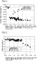
- FIG. 1 shows a relationship between the presence density of iron-based carbide having an equivalent circle diameter ranging from 0.15 ⁇ m to 0.50 ⁇ m and the residual shear strain amount
- FIG. 1 shows a relationship between the presence density of iron-based carbide having an equivalent circle diameter ranging from 0.15 ⁇ m to 0.50 ⁇ m and the residual shear strain amount
- test No. 1 to 47 were Examples of the present invention satisfying the requirements regulated in the present invention. In these examples, it had been found that excellent settling resistance such as the residual shear strain amount of 0.029% or less were obtained while workability of reduction in area of 50% or more was maintained.
- the prior austenite grain size or the presence density of iron-based carbide satisfied the range of the regulation of the present invention.
- the area ratio of the tempered martensite was less than 90%, the residual shear strain amount was large and the settling resistance was low.
- the prior austenite grain size number was less than 12.5.
- the residual shear strain amount was large and the settling resistance was low.
- the area ratio of the tempered martensite satisfied the range of the regulation of the present invention.
- the prior austenite grain size number was less than 12.5
- the presence density of iron-based carbide having an equivalent circle diameter ranging from 0.15 ⁇ m to 0.50 ⁇ m was less than 0.40 pieces/ ⁇ m 2 .
- the residual shear strain amount was large and the settling resistance was low.
- the area ratio of the tempered martensite and the prior austenite grain size satisfied the range of the regulation of the present invention.
- the presence density of iron-based carbide having an equivalent circle diameter ranging from 0.15 ⁇ m to 0.50 ⁇ m exceeded 2.00 pieces/ ⁇ m 2 .
- the reduction in area, that is, the workability was low.
Landscapes
- Chemical & Material Sciences (AREA)
- Engineering & Computer Science (AREA)
- Mechanical Engineering (AREA)
- Organic Chemistry (AREA)
- Materials Engineering (AREA)
- Metallurgy (AREA)
- Thermal Sciences (AREA)
- Crystallography & Structural Chemistry (AREA)
- Physics & Mathematics (AREA)
- General Engineering & Computer Science (AREA)
- Manufacturing & Machinery (AREA)
- Heat Treatment Of Steel (AREA)
- Heat Treatment Of Strip Materials And Filament Materials (AREA)
- Springs (AREA)
Abstract
Description
- The present invention relates to a spring steel wire used for high strength springs such as valve springs, clutch damper springs, and suspension springs which are mainly used for automobiles, and particularly relates to a high strength spring steel wire having excellent settling resistance after coiliing, and a spring including the steel wire.
- Priority is claimed on Japanese Patent Application No.
2015-174730, filed on September 4, 2015 - As automobiles progress in weight reduction and high performance, increase of design stress for springs used for various purposes as described above are also aimed at. In this case, since spring load stress increases, springs having excellent fatigue strength and settling resistance is required. Settling denotes plastic deformation under a stress load. Therefore, in a case where the settling resistance is low, there is a problem that the settling amount of a spring increases under a high-stress load and restoring force of the spring is degraded.
- As the springs used for various purposes as described above, cold formed springs are mainly employed. The cold formed springs are manufactured by carrying out cold coiliing with high strength steel wires in which steel has been subjected to quenching and tempering in advance. Generally, as a technique of improving fatigue strength and settling resistance of such springs, the measure, in which tensile strength after quenching and tempering is enhanced, is well known.
- In addition, as disclosed in Patent Documents 1 and 2, technologies of improving fatigue strength and settling resistance have been proposed. In the technologies, tensile strength of a steel wire is enhanced by containing a large amount of an alloying element as a chemical composition such as Si. However, when tensile strength of a steel wire is enhanced using such a technique, there is concern that ductility and toughness are remarkably degraded such that coiliing cannot be carried out, or an obtained spring cannot bear use as a spring.
- In addition to that described above, in the related art, various techniques of improving settling resistance have been proposed. For example, Patent Document 3 proposes a technology of improving settling resistance of a spring by causing fine cementite of 100 nm or smaller to be dispersed in steel. However, in Patent Document 3, in order to restrain this fine cementite from decomposing and dissipating during heat treatment, there is a need to cause Cr and V to be concentrated in the cementite such that the concentration of Cr and the concentration of V reach a predetermined concentration or higher. The fine cementite in which alloying elements such as Cr and V are concentrated has remarkably low ductility and toughness. Therefore, in the technology of Patent Document 3, there is concern that coiliing for obtaining a spring from a steel wire cannot be carried out, or an obtained spring cannot bear use as a spring.
- In addition, Patent Document 4 has proposed a technology of improving settling resistance of a suspension spring. In the technology, steel mainly including a structure of martensite and bainite is subjected to cold working. Thereafter, quenching and tempering are performed. Then, prior austenite grains are refined, and undissolved carbide is reduced as much as possible. However, in the technology of Patent Document 4, there is a need to carry out cold working for spring steel mainly including the structure of martensite and bainite. The structure of martensite and bainite in high carbon steel such as spring steel is brittle so that it is difficult to carry out cold working.
- Furthermore, Patent Documents 5 to 8 have also proposed technologies of improving fatigue properties or settling resistance by reducing the amount of undissolved carbide (cementite). However, in such technologies, the effect of improving fatigue properties or settling resistance is small.
- As described above, the technologies of improving settling resistance which have been proposed in the related art are still insufficient and high strength spring steel wires which can cope with recent demands for high strengthening of springs and can improve settling resistance of springs have not been realized at present.
-
- [Patent Document 1] Japanese Patent No.
2613601 - [Patent Document 2] Japanese Unexamined Patent Application, First Publication No.
H2-57637 - [Patent Document 3] Japanese Patent No.
4868935 - [Patent Document 4] Japanese Patent No.
3764715 - [Patent Document 5] Japanese Patent No.
3233188 - [Patent Document 6] Japanese Unexamined Patent Application, First Publication No.
H11-246943 - [Patent Document 7] Japanese Patent No.
3971571 - [Patent Document 8] Japanese Patent No.
3851095 - The present invention has been made based on the foregoing circumstances. An object of the present invention is to provide a high strength spring steel wire which has favorable workability, in which the amount of plastic deformation is small even when being used under a high-stress load after coiliing, and which has excellent settling resistance to the extent of being able to sufficiently cope with recent demands for high strengthening, and a spring including the spring steel wire.
- In order to achieve the object, the inventors have intensively examined measures for realizing a high strength spring steel wire having excellent settling resistance after coiliing. The following (a) to (e) are results of the acquired knowledge.
- (a) In order to improve settling resistance, it is effective to cause the structure of a spring steel wire (metallographic structure) to be a structure having tempered martensite as a main constituent (specifically, a structure, by area ratio, having tempered martensite of 90% or more), and at the same time to refine the structure, particularly to refine prior austenite grains. Generally, in a process of manufacturing a spring steel wire, pearlitic transformation treatment such as lead patenting is performed with respect to steel having a structure including austenite after hot rolling. Thereafter, cold wire-drawing is performed, and then quenching and tempering are performed. If the structure after quenching and tempering is a structure having tempered martensite as a main constituent, particularly, a structure, by area ratio, having tempered martensite of 90% or more, excellent settling resistance can be ensured.
- (b) In order to improve settling resistance, it is effective to refine the structure, particularly to refine prior austenite grains. If austenite grains before transformation are refined, the size of martensite blocks in a structure having tempered martensite as a main constituent is refined. In addition, due to the refined martensite block size, yield strength is improved and settling resistance is improved. These effects are particularly maximized when the size of prior austenite grains matches that of No. 12.5 or higher in the grain size numbers regulated by JIS G 0551.
- (c) In order to achieve refinement of prior austenite grains, it is effective to cause a large amount of iron-based carbide represented by cementite (Fe3C), particularly comparatively large iron-based carbide (iron-based carbide having undissolved iron-based carbide as a main constituent, as described below) having a grain size of a certain degree or larger to be dispersed. In the related art, it has been considered that it is favorable to have no coarse carbide. However, when a large amount of comparatively large iron-based carbide is dispersed, austenite grains before transformation can be refined due to the pinning effect of the iron-based carbide. When the austenite grains before transformation are refined, martensite, which has been formed by transformation in a cooling process thereafter, is refined, so that yield strength is improved without having workability degraded. Therefore, settling resistance is improved.
- (d) In the iron-based carbide described above, its grain size is important. It is difficult to sufficiently exhibit the effects described above in fine iron-based carbide having an equivalent circle diameter less than 0.15 µm and coarse iron-based carbide having an equivalent circle diameter exceeding 0.50 µm. Therefore, in order to achieve the effect, there is a need to cause a predetermined amount or more of iron-based carbide having an equivalent circle diameter ranging from 0.15 µm to 0.50 µm to be present. In the process of manufacturing a spring steel wire, there are cases where a part of carbide such as cementite generated through pearlitic transformation treatment such as lead patenting after hot rolling remains undissolved without being completely dissolved even after quenching and tempering thereafter. Such undissolved iron-based carbide is often present as carbide having an equivalent circle diameter of approximately 0.15 µm or larger. Meanwhile, iron-based carbide is precipitated even during tempering after quenching. However, carbide which is precipitated during tempering is fine, and the equivalent circle diameter is less than 0.15 µm, particularly, the equivalent circle diameter is mostly less than 0.10 µm. Therefore, in order to refine austenite grains before transformation and to improve settling resistance, it is effective to utilize iron-based carbide which remains undissolved even after quenching and tempering.
- (e) In order to improve settling resistance, controlling the presence density of iron-based carbide is also important. That is, if an amount of iron-based undissolved carbide having an equivalent circle diameter ranging from 0.15 µm to 0.50 µm is small, since the effect of refining grains is not sufficient, settling resistance is not improved. Particularly, when its presence density is less than 0.40 pieces/µm2, the effect of improving settling resistance is scarcely recognized. Meanwhile, in a case where iron-based carbide having an equivalent circle diameter ranging from 0.15 µm to 0.50 µm is excessively present, since strength after quenching and tempering is degraded, settling resistance is degraded, on the contrary. In addition, in this case, since ductility is also degraded, workability is remarkably degraded. Particularly, when its presence density exceeds 2.00 pieces/µm2, these problems are likely to occur. Therefore, in order to reliably improve settling resistance without impairing workability, the presence density of iron-based carbide having an equivalent circle diameter ranging from 0.15 µm to 0.50 µm needs to be within a range of 0.40 pieces/µm2 to 2.00 pieces/µm2.
- Based on the knowledge described above as in (a) to (e), the inventors have found that settling resistance after coiliing can be reliably and sufficiently improved without impairing workability, when a structure of a steel wire includes, by area ratio, tempered martensite of 90% or more, when at the same time, the prior austenite grain size number is No. 12.5 or higher, and when furthermore, the presence density of iron-based carbide having an equivalent circle diameter ranging from 0.15 µm to 0.50 µm ranges from 0.40 pieces/µm2 to 2.00 pieces/µm2, and have attained the present invention.
- The gist of the present invention is as follows.
- (1) According to an aspect of the present invention, there is provided a spring steel wire including, by mass%, C: 0.40% to 0.75%, Si: 1.00% to 5.00%, Mn: 0.20% to 2.00%, P: 0.0001% to 0.0500%, S: 0.0001% to 0.0500%, Cr: 0.50% to 3.50%, Al: 0.0005% to 0.0500%, N: 0.0020% to 0.0100%, Mo: 0% to 2.00%, V: 0% to 0.50%, W: 0% to 0.50%, Nb: 0% to 0.100%, Ti: 0% to 0.100%, Ca: 0% to 0.0100%, Mg: 0% to 0.0100%, Zr: 0% to 0.1000%, B: 0% to 0.0100%, Cu: 0% to 1.00%, Ni: 0% to 3.00%, and a remainder of Fe and impurities. A structure includes, by area ratio, a tempered martensite of 90% or more. The prior austenite grain size number is No. 12.5 or higher. The presence density of iron-based carbide having an equivalent circle diameter ranging from 0.15 µm to 0.50 µm is 0.40 pieces/µm2 to 2.00 pieces/µm2.
- (2) In the spring steel wire according to (1), the spring steel wire may include, by mass%, at least one of Mo: 0.01% to 2.00%, V: 0.01% to 0.50%, W: 0.01% to 0.50%, Nb: 0.005% to 0.100%, and Ti: 0.001% to 0.100%.
- (3) In the spring steel wire according to (1) or (2), the spring steel wire may include, by mass%, at least one of Ca: 0.0002% to 0.0100%, Mg: 0.0002% to 0.0100%, Zr: 0.0005% to 0.1000%, B: 0.0005% to 0.0100%, Cu: 0.05% to 1.00%, and Ni: 0.05% to 3.00%.
- (4) According to another aspect of the present invention, there is provided a spring including the spring steel wire according to any one of (1) to (3).
- According to the present invention, it is possible to provide a high strength spring steel wire having excellent settling resistance after coiliing while favorable workability is ensured, and a spring including the spring steel wire.
-
-
FIG. 1 is a graph showing a relationship between presence density of iron-based carbide having an equivalent circle diameter ranging from 0.15 µm to 0.50 µm, and a residual shear strain amount which is an index for settling resistance. -
FIG. 2 is a graph showing a relationship between presence density of iron-based carbide having an equivalent circle diameter ranging from 0.15 µm to 0.50 µm, and reduction in area which is an index for workability. - Hereinafter, a spring steel wire according to an embodiment of the present invention (hereinafter, a spring steel wire according to the present embodiment) and a spring according to an embodiment of the present invention (hereinafter, according to a spring of the present embodiment) will be described.
- First, the reasons for limiting the chemical composition of the spring steel wire in the present invention will be described. Hereinafter, the percentage sign "%" of the amount of each component indicates "mass%".
- C is an important element determining strength of steel. In order to obtain sufficient strength, the lower limit is set to 0.40%, is preferably set to 0.45% or more, and is more preferably set to 0.50% or more. Since the alloying cost of C is low compared to other strengthening elements, if a large amount of C can be contained, high strength can be obtained at a low alloying cost. However, when C is excessively contained, the ductility and toughness are degraded so that the workability is remarkably degraded. Therefore, the upper limit for the C content is set to 0.75%. The C content is preferably set to 0.67% or less and is more preferably set to 0.65% or less.
- Si is an element having deoxidizing action. In addition, since Si is element which significantly suppresses softening of steel after heat treatment, Si is an element effective in improving settling resistance. In order to sufficiently obtain such an effect, the lower limit is set to 1.00%. The Si content is preferably set to 1.20% or more. Meanwhile, when Si is excessively contained, ductility and toughness of steel are degraded so that workability is remarkably degraded. Therefore, the upper limit for the Si content is set to 5.00%. The Si content is preferably set to 3.50% or less.
- Mn is an element which fixes S in steel as MnS and is effective in enhancing hardenability such that hardness after heat treatment is sufficiently improved. In order to achieve these effects, the Mn content is set to 0.20% or more, is preferably set to 0.25% or more, and is more preferably set to 0.30% or more. Meanwhile, when Mn content exceeds 2.00%, hardness of the base (matrix) increases and steel becomes brittle, so that workability is remarkably degraded. Therefore, the Mn content is set to 2.00% or less. The Mn content is preferably set to 1.50% or less and is more preferably set to 1.20% or less.
- Generally, P is included in steel by 0.0001% or more as impurities. Therefore, the lower limit is set to 0.0001%. P is an element being segregated in prior austenite grain boundaries and the like, so that steel becomes prominently brittle and workability is remarkably degraded. When the P content exceeds 0.0500%, the adverse influence becomes prominent. Therefore, the upper limit for the P content is set to 0.0500%. The P content is preferably 0.0300% or less, is more preferably set to 0.0200% or less, and is still more preferably set to 0.0150% or less.
- Generally, similar to P, S is also included in steel by 0.0001% or more as impurities. Therefore, the lower limit for the S content is set to 0.0001%. S is an element causing steel to be brittle. Accordingly, it is desirable that the S content is reduced as much as possible. Particularly, when the S content exceeds 0.0500%, the adverse influence becomes prominent. Therefore, the upper limit for the S content is set to 0.0500%. The amount of S is preferably set to 0.0300% or less, is more preferably set to 0.0200% or less, and is still more preferably set to 0.0150% or less.
- Cr is an element effective in improving settling resistance due to its effect of suppressing softening after heat treatment. In order to reliably obtain this effect, the Cr content is set to 0.50% or more, is preferably set to 0.60% or more, and is more preferably set to 0.70% or more. However, Cr is solid-solubilized in iron-based carbide and stabilizes the carbide. Therefore, when there is an excessive amount of Cr, iron-based undissolved carbide increases more than necessary, so that strength after heat treatment is degraded. In this case, settling resistance is degraded, on the contrary. When there is an excessive amount of Cr, ductility is degraded, and the workability is remarkably degraded. From these viewpoint, the Cr content is set to 3.50% or less, is preferably set to 3.00% or less, and is more preferably set to 2.75% or less.
- Generally, Al is included in steel by 0.0005% or more as impurities. Therefore, the lower limit for the Al content is set to 0.0005%. Al is an element forming oxide such as Al2O3, such that ductility and toughness of steel are degraded and workability is remarkably degraded. Therefore, the Al content is set to 0.0500% or less. It is desirable that the Al content is reduced as much as possible. The Al content is preferably set to 0.0100% or less.
- N is an element which combines with Al, V, Ti, and/or Nb in steel and forms nitride. This nitride has an effect of refining prior austenite grains. In order to achieve this effect, the N content is set to 0.0020% or more and is preferably set to 0.0030% or more. Meanwhile, when there is an excessive amount of N, the nitride is coarsened. As a result, ductility of steel is degraded and workability is remarkably degraded. Therefore, the N content is set to 0.0100% or less and is preferably set to 0.0070% or less.
- Basically, the spring steel wire according to the present embodiment includes the elements described above, and the remainder includes Fe and impurities. However, in order to further improve the characteristics, in place of a part of Fe, at least one of Mo: 0.01% to 2.00%, V: 0.01% to 0.50%, W: 0.01% to 0.50%, Nb: 0.005% to 0.100%, and Ti: 0.001% to 0.100%; and/or at least one of Ca: 0.0002% to 0.0100%, Mg: 0.0002% to 0.0100%, Zr: 0.0005% to 0.1000%, B: 0.0005% to 0.0100%, Cu: 0.05% to 1.00%, and Ni: 0.05% to 3.00% may be contained. However, all of Mo, V, W, Nb, Ti, Ca, Mg, Zr, B, Cu, and Ni are not necessarily contained, and their lower limits are 0%.
- Mo, V, W, Nb, and Ti are elements contributing to improvement of settling resistance by suppressing softening after heat treatment. In order to achieve this effect, the amounts of Mo, V, and W are preferably set to 0.01% or more. The amount of Nb is preferably set to 0.005% or more. In addition, the amount of Ti is preferably set to 0.001% or more. Meanwhile, when there are excessive amounts of these elements, metal carbonitride increases and strength after heat treatment is degraded. Accordingly, settling resistance is degraded, on the contrary. In addition, since ductility is degraded, workability is remarkably degraded. Therefore, even in a case where these elements are contained, it is preferable that the upper limit for the Mo content is set to 2.00%, the upper limit for the V content is set to 0.50%, the upper limit for the W content is set to 0.50%, the upper limit for the Nb content is set to 0.100%, and the upper limit for the Ti content is set to 0.100%. It is more preferable that the Mo content ranges from 0.05% to 0.60%, the V content ranges from 0.05% to 0.35%, the W content ranges from 0.05% to 0.35%, the Nb content ranges from 0.005% to 0.050%, and the Ti content ranges from 0.010% to 0.080%.
- All of Ca, Mg, and Zr are elements having an effect of improving hardness of steel after heat treatment by forming oxide, becoming crystallized nuclei of MnS, causing the MnS to be finely dispersed in a uniform manner, and enhancing hardenability by means of the MnS. In addition, all of B, Cu, and Ni are elements having an effect of improving hardness after heat treatment by being solid-solubilized in steel and enhancing hardenability. In order to exhibit these effects, it is preferable that the lower limits for the amounts of Ca and Mg are set to 0.0002%, the lower limit for the amount of Zr is set to 0.0005%, the lower limit for the amount of B is set to 0.0005%, the lower limit for the amount of Cu is set to 0.05%, and the lower limit for the amount of Ni is set to 0.05%. Meanwhile, if the Ca content and the Mg content exceed 0.0100% and if the Zr content exceeds 0.1000%, hard inclusions such as oxide, sulfide, and the like are excessively formed, so that ductility of steel is degraded and workability is remarkably degraded. In addition, when the B content exceeds 0.0100%, when the Cu content exceeds 1.00%, and the Ni content exceeds 3.00%, ductility of steel is degraded and workability is remarkably degraded. Therefore, even in a case where these elements are contained, it is preferable that the upper limits for the Ca content and the Mg content are set to 0.0100%, the upper limit for the Zr content is set to 0.1000%, the upper limit for the B content is set to 0.0100%, the upper limit for the Cu content is set to 1.00%, and the upper limit for the Ni content is set to 3.00%.
- The spring steel wire according to the present embodiment includes a chemical composition containing the essential elements and a remainder including Fe and impurities, or a chemical composition containing the optional elements described above in addition to the essential elements, and a remainder of Fe and impurities. As impurities other than those described above, O and the like are considered, and their amounts are preferably set to 0.05% or less in total.
- Next, the reasons for limiting the structure of the spring steel wire according to the present embodiment will be described.
- When the structure of the spring steel wire is a structure having tempered martensite as a main constituent, excellent settling resistance can be obtained. As phases other than the tempered martensite (remainder structures), there are ferrite, pearlite, bainite, residual austenite, and the like. When the total area ratio of these structures (remainder structures) increases, settling resistance is degraded. On the contrary, when the remainder structures are further reduced, settling resistance is further improved.
- Particularly, when the total area ratio of the remainder structures exceeds 10%, settling resistance is remarkably degraded. Therefore, the remainder structures are set to less than 10% by total area ratio. That is, the area ratio of the tempered martensite is regulated to 90% or higher. The residual shear strain amount that is an index value for settling resistance can be set to 0.029% or less by setting the area ratio of the tempered martensite to 90% or more and controlling the prior austenite grain size, the iron-based carbide size, and the distribution state, which will be described below. The area ratio of the tempered martensite may be 100%.
- The area ratio of the tempered martensite needs only to be 90% or more by average area ratio when a cross section (C-cross section) of a spring steel wire orthogonal to the length direction after quenching and tempering is observed and image analysis is performed. Actually, for example, as seen in Examples described below, the area ratio of the tempered martensite may be represented by a value measured at a 1/4 position of a diameter D from a location on the outer circumferential surface of a steel wire in the C-cross section of the steel wire. For example, the area ratio of martensite may be obtained by collecting a sample from a 1/4 portion of the diameter D from the outer circumferential surface in the C-cross section of the steel wire, performing etching using a nital etching solution, capturing five photographs of the structure of 1,000-fold using an optical microscope, and performing image analysis.
- When prior austenite grains are refined, the size of martensite blocks is refined. Accordingly, yield strength is improved. As a result, settling resistance is improved. These effects get larger particularly through refinement in which the prior austenite grain size number is No. 12.5 or higher. Therefore, the prior austenite grain size number is set to No. 12.5 or higher. The prior austenite grain size number is preferably set to No. 13.5 or higher, is more preferably set to No. 14.0 or higher, and is still more preferably set to No. 14.5 or higher. Since it is preferable for the prior austenite grain size to be small, there is no need to provide an upper limit for the grain size number.
- The prior austenite grain size number needs only to be measured by observing prior austenite grain boundaries which are revealed through etching using an appropriate etching solution such as a picric acid saturated aqueous solution using an optical microscope or the like. Representatively, the measurement may be performed in accordance with JIS G 0551. In addition, the prior austenite grain size needs only to be measured in a cross section (C-cross section) of a spring steel wire orthogonal to the length direction after quenching and tempering. Actually, for example, as seen in Examples described below, the prior austenite grain size number may be represented by a value measured at a 1/4 position of the diameter D from a location on the outer circumferential surface of a steel wire in the C-cross section of the steel wire after quenching and tempering.
- In order to refine the prior austenite grains, it is effective to suppress grain growth of austenite before martensite transformation by means of an pinning effect of precipitates. In order to refine austenite before transformation such that the prior austenite grain size number becomes No. 12.5 or higher, without impairing workability, it is effective when precipitates having an equivalent circle diameter ranging from 0.10 µm to 0.50 µm, particularly among thereof, precipitates having an equivalent circle diameter ranging from 0.15 µm to 0.50 µm are present in a dispersed manner at a density ranging from 0.40 pieces/µm2 to 2.00 pieces/µm2.
- Here, when the equivalent circle diameter is less than 0.15 µm or exceeds 0.50 µm, or when the presence density of precipitates is less than 0.40 pieces/µm2, the pinning effect of grain growth of austenite is small and sufficient refinement of austenite grains cannot be obtained. Therefore, the effect of improving settling resistance cannot be sufficiently obtained. In accordance with an increase of the presence density of precipitates, the prior austenite grain size number increases and settling resistance are improved. However, when the presence density of precipitates exceeds 2.00 pieces/µm2, strength after quenching and tempering is degraded, so that settling resistance is degraded, on the contrary. In addition, since ductility is also degraded, workability is remarkably degraded. Therefore, there is a need for precipitates having an equivalent circle diameter ranging from 0.15 µm to 0.50 µm to be dispersed at a density ranging from 0.40 pieces/µm2 to 2.00 pieces/um2.
- Furthermore, when there are 0.50 pieces/µm2 or more of precipitates having equivalent circle diameters ranging from 0.15 µm to 0.50 µm, the prior austenite grain size number becomes No. 13.5 or higher, which is more preferable.
- In order to obtain precipitates having the size and the amount as described above, it is necessary that precipitates is iron-based carbide such as cementite (Fe3C). However, even though precipitates are iron-based carbide, iron-based carbide precipitated during tempering is fine, and the foregoing conditions are not often satisfied. Therefore, it is preferable that iron-based carbide satisfying the foregoing conditions has comparatively large iron-based undissolved carbide as a main constituent which has remained undissolved during heating before quenching. In addition, for example, since nitride and the like are drastically smaller than the size described above, a sufficient pinning effect cannot be obtained compared to iron-based carbide.
- As described above, when the spring steel wire according to the present embodiment simultaneously satisfies three conditions, such as the spring steel wire includes, as a structure, by area ratio, a structure of tempered martensite of 90% or more, the prior austenite grain size number is No. 12.5 or higher, and the presence density of iron-based carbide having an equivalent circle diameter ranging from 0.15 µm to 0.50 µm is 0.40 pieces/µm2 to 2.00 pieces/µm2, excellent settling resistance can be obtained without impairing workability.
- The spring according to the present embodiment includes the spring steel wire according to the present embodiment. Specifically, the spring according to the present embodiment is obtained by carrying out cold coiliing with the spring steel wire according to the present embodiment. Even though coiliing is carried out, there is no change in the chemical composition and the presence state of carbide. Therefore, the chemical composition and the presence state of carbide in the spring according to the present embodiment including the spring steel wire according to the present embodiment are the same as those in the spring steel wire according to the present embodiment.
- Next, preferable methods of manufacturing the spring steel wire according to the present embodiment and the spring according to the present embodiment will be described.
- The spring steel wire according to the present embodiment can achieve the foregoing effects as long as the spring steel wire has the features described above. Therefore, the manufacturing method is not particularly limited. However, for example, when pearlitic transformation treatment such as lead patenting is performed with respect to a steel wire rod obtained through casting and hot rolling in accordance with the routine procedure, at a temperature higher than a general temperature range (patenting process), then, cold drawing is performed to a predetermined diameter, and thereafter, the heating temperature before quenching is controlled and quenching and tempering are performed (quenching and tempering process), the spring steel wire can be stably obtained, which is preferable.
- Hereinafter, preferable conditions for the patenting process and the quenching and tempering process will be described.
- Pearlitic transformation treatment such as lead patenting is performed with respect to a steel wire rod obtained through casting and hot rolling. Generally, in consideration of productivity and the like, pearlitic transformation treatment is performed at a temperature (approximately from 550°C to 600°C) in the vicinity of a pearlite nose in an isothermal transformation diagram (TTT curve). However, in a case where the spring steel wire according to the present embodiment is manufactured, it is preferable that patenting is performed within a range from 650°C to 750°C. When the patenting temperature is set to 650°C or higher, Cr and Mn are concentrated in cementite, so that iron-based carbide is unlikely to be dissolved during quenching and tempering. As a result, the main constituent of iron-based carbide becomes undissolved carbide, so that iron-based carbide having desired size and presence density can be obtained.
- Quenching and tempering are performed with respect to a steel wire rod which has been subjected to cold drawing to a predetermined diameter after pearlitic transformation treatment such as patenting is performed. In order to realize the structure as described above, it is preferable to appropriately control the heating temperature before quenching. In order to have tempered martensite of 90% or more after quenching and tempering, it is preferable that the heating temperature before quenching is 870°C or higher.
- In addition, in the related art, since undissolved carbide has been considered to cause deterioration of characteristics, the heating temperature before quenching has been set near the temperature at which cementite (iron-based carbide) formed through pearlitic transformation treatment is solid-solubilized completely. However, in the spring steel according to the present embodiment, it is preferable that undissolved carbide remains. In order to satisfy the structure conditions as described above, it is preferable that the heating temperature before quenching is set lower than that in the related art, specifically lower than a temperature at which iron-based carbide is solid-solubilized completely, by a range approximately from 10°C to 40°C.
- The temperature at which iron-based carbide is solid-solubilized completely varies depending on the chemical composition of steel. Therefore, the temperature at which iron-based carbide is solid-solubilized completely can be obtained in advance using a sample having a similar chemical composition, and a temperature lower than the obtained temperature by a range from 10°C to 40°C may be set as the heating temperature before quenching.
- In addition, tempering may be performed under known conditions.
- Next, the method of manufacturing the spring according to the present embodiment will be described.
- As long as the spring according to the present embodiment is manufactured using the spring steel wire according to the present embodiment obtained as described above, its manufacturing conditions and the like are not particularly limited and need only to follow the routine procedure. For example, after cold spring forming is performed with a spring steel wire which is obtained through quenching and tempering as described above, annealing or nitriding may be performed as necessary.
- The present invention will be described below in detail with reference to Examples. These Examples are for describing the technical significance and the effects of the present invention and do not limit the scope of the present invention.
- Pieces of ingot steel melted in converter having compositions indicated as kinds of steel A to Z in Table 1 and kinds of steel AA to AV in Table 2 were continuously cast and were made into 162 mm-square rolling materials via a soaking process and a blooming process as necessary. Thereafter, the rolling materials were heated to 1,150°C and were made into steel wire rods of φ8.0 mm through hot rolling. The steel wire rods were subjected to surface scalping to φ7.4 mm and were heated to 950°C. Thereafter, lead patenting treatment was performed at temperatures indicated in Tables 3 and 4. After cold wire-drawing was performed to φ4.0 mm, quenching and tempering were performed. The iron-based carbide size and the presence density in each steel wire were changed by varying the heating temperature before quenching within the ranges indicated in Tables 3 to 4. In addition, the structures were changed by adjusting the degree of agitation (0 cm/sec to 50 cm/sec) using a water soluble quenching solution (solution temperature of 40°C) and varying the cooling rate. Thereafter, tempering was performed for 90 seconds within a temperature range from 430°C to 500°C. Table 3 and Table 4 shows the conditions for quenching and tempering which are performed with respect to each kind of steel.
[Table 1] Kind of steel Chemical composition (mass%) *Remainder of Fe and impurities C Si Mn P S Cr Al Mo V W Nb Ti Ca Mg Zr B Cu Ni N A 0.61 2.75 0.89 0.003 0.004 1.32 0.0029 - - - - - - - - - - - 0.0045 B 0.64 2.10 0.67 0.004 0.003 2.73 0.0023 - - - - - - - - - - - 0.0052 C 0.43 1.24 0.77 0.003 0.004 2.11 0.0041 0.57 - - - - - - - - - - 0.0040 D 0.58 2.23 0.85 0.005 0.004 1.02 0.0023 - 0.28 - - - - - - - - - 0.0069 E 0.61 2.08 0.92 0.003 0.005 1.23 0.0028 - - 0.45 - - - - - - - - 0.0032 F 0.61 1.98 0.87 0.004 0.006 1.19 0.0019 - - - 0.042 - - - - - - - 0.0057 G 0.63 2.24 0.75 0.005 0.005 1.16 0.0032 - - - - 0.04 - - - - - - 0.0056 H 0.58 3.42 0.65 0.005 0.003 1.25 0.0031 0.15 0.12 - - - - - - - - - 0.0064 I 0.55 2.14 1.02 0.003 0.005 0.98 0.0024 0.17 - 0.14 - - - - - - - - 0.0041 J 0.62 2.08 0.84 0.007 0.007 1.37 0.0010 0.18 - - 0.011 - - - - - - - 0.0048 K 0.61 2.12 1.12 0.006 0.004 1.10 0.0021 0.21 - - - 0.05 - - - - - - 0.0058 L 0.58 2.54 1.17 0.006 0.006 1.14 0.0026 - 0.19 0.17 - - - - - - - - 0.0046 M 0.60 2.18 0.53 0.003 0.004 1.27 0.0019 - 0.23 - 0.023 - - - - - - - 0.0046 N 0.60 1.98 0.87 0.005 0.005 1.28 0.0028 - 0.21 - - 0.05 - - - - - - 0.0042 O 0.57 1.94 0.83 0.005 0.005 1.31 0.0021 - - 0.22 0.018 - - - - - - - 0.0058 P 0.58 2.31 0.95 0.004 0.003 1.34 0.0024 - - 0.19 - 0.04 - - - - - - 0.0061 Q 0.57 2.12 0.91 0.006 0.005 1.27 0.0038 - - - 0.021 0.06 - - - - - - 0.0052 R 0.54 2.26 0.74 0.006 0.004 1.57 0.0023 - - - - - 0.0012 - - - - - 0.0037 S 0.61 2.06 0.93 0.005 0.004 1.97 0.0037 - - - - - - 0.0011 - - - - 0.0042 T 0.63 2.00 0.86 0.005 0.003 1.43 0.0011 - - - - - - - 0.0027 - - - 0.0051 U 0.58 2.08 0.76 0.005 0.006 1.19 0.0020 - - - - - - - - 0.0022 - - 0.0054 V 0.59 2.18 0.94 0.006 0.004 1.27 0.0033 - - - - - - - - - 0.12 0.27 0.0043 W 0.60 1.97 1.12 0.006 0.005 0.75 0.0028 - - - - - 0.0031 0.0022 - - - - 0.0037 X 0.59 1.91 0.94 0.004 0.003 1.35 0.0022 - - - - - 0.0018 - 0.0021 - - - 0.0061 Y 0.60 2.23 0.78 0.005 0.006 1.34 0.0032 - - - - - 0.0024 - - 0.0034 - - 0.0038 Z 0.61 2.37 0.88 0.005 0.005 1.21 0.0038 - - - - - 0.0028 - - - 10.18 0.21 0.0054 [Table 2] Kind of steel Chemical composition (mass%) *Remainder of Fe and impurities C Si Mn P S Cr Al Mo V W Nb Ti Ca Mg Zr B Cu Ni N AA 0.54 2.34 0.72 0.003 0.004 1.52 0.0017 - - - - - - 0.0013 0.0014 - - - 0.0052 AB 0.57 2.11 0.94 0.004 0.006 1.08 0.0022 - - - - - - 0.0018 - 0.0041 - - 0.0049 AC 0.59 1.95 0.87 0.006 0.005 1.24 0.0040 - - - - - - 0.0021 - - 0.23 0.54 0.0034 AD 0.62 2.07 1.03 0.006 0.004 1.28 0.0034 - - - - - - - 0.0048 0.0028 - - 0.0046 AE 0.61 2.16 0.94 0.007 0.003 1.34 0.0028 - - - - - - - 0.0024 - 0.31 0.37 0.0054 AF 0.59 2.07 0.87 0.003 0.006 1.02 0.0029 - - - - - - - - 0.0031 0.27 0.44 0.0046 AG 0.62 2.17 0.98 0.005 0.005 1.24 0.0019 - - - - - 0.0016 0.0018 0.0031 - - - 0.0032 AH 0.60 2.40 0.75 0.004 0.003 1.15 0.0042 0.12 - - - - 0.0021 - 0.0057 0.0025 - - 0.0067 AI 0.62 1.94 1.18 0.003 0.006 0.94 0.0033 - 0.25 - - - 0.0025 0.0009 - - 0.28 0.52 0.0054 AJ 0.54 1.87 0.74 0.007 0.003 1.25 0.0011 - - 0.16 - - - 0.0014 0.0016 - - - 0.0040 AK 0.58 2.23 0.62 0.005 0.005 1.31 0.0020 - - - 0.017 - - - 0.0018 0.0038 - - 0.0048 AL 0.58 2.06 0.97 0.003 0.005 0.87 0.0017 0.22 0.15 - - - 0.0014 - - - - - 0.0044 AM 0.75 2.21 0.86 0.006 0.004 1.21 0.0012 - - - - - - - - - - - 0.0052 AN 0.59 2.32 0.81 0.005 0.003 3.48 0.0018 - - - - - - - - - - - 0.0054 AO 0.58 1.03 0.84 0.006 0.005 1.05 0.0020 - - - - - - - - - - - 0.0046 AP 0.60 4.97 0.84 0.005 0.004 1.30 0.0026 - - - - - - - - - - - 0.0060 AQ 0.58 2.17 0.21 0.006 0.005 1.25 0.0023 - - - - - - - - - - - 0.0057 AR 0.59 2 22 0.80 0.005 0.004 0.51 0.0017 - - - - - - - - - - - 0.0055 AS 0.59 2.14 0.83 0.005 0.004 1.32 0.0495 - - - - - - - - - - - 0.004 7 AT 0.58 2.08 0.83 0.004 0.005 1.28 0.0025 - - - - - - - - - - - 0.0097 AU 0.60 2.26 1.98 0.005 0.006 1.18 0.0028 - - - - - - - - - - - 0.0054 AV 0.59 2.17 0.87 0.005 0.004 4.02 0.0015 - - - - - - - - - - - 0.0049 [Table 3] Test No. Kind of steel Patenting conditions Quenching and tempering conditions Temperature for complete solid-solution of cementite (°C) Temperature (°C) Heating temperature (°C) Agitation of quenching solution (cm/sec) Tempering temperature (°C) 1 A 710 890 50 455 920 2 B 710 940 50 475 970 3 C 710 910 50 455 940 4 D 710 880 50 455 910 5 E 710 890 50 450 920 6 F 710 890 50 440 920 7 G 710 890 50 440 920 8 H 710 890 50 480 920 9 I 710 880 50 445 910 10 J 710 895 50 450 925 11 K 710 880 50 450 910 12 L 710 890 50 465 920 13 M 710 890 50 455 920 14 N 710 890 50 455 920 15 O 710 895 50 440 925 16 P 710 890 50 445 920 17 Q 710 890 50 440 920 18 R 710 900 50 445 930 19 S 710 910 50 455 940 20 T 710 895 50 445 925 21 U 710 890 50 435 920 22 V 710 890 50 440 920 23 W 710 880 50 430 910 24 X 710 895 50 440 925 25 Y 710 890 50 445 920 26 Z 710 890 50 445 920 27 AA 710 900 50 445 930 28 AB 710 885 50 435 915 29 AC 710 890 50 435 920 30 AD 710 890 50 445 920 31 AE 710 890 50 445 920 32 AF 710 885 50 435 915 33 AG 710 890 50 445 920 [Table 4] Test No. Kind steel Patenting conditions Quenching and tempering conditions Temperature for complete solid-solution of cementite (°C) Temperature (°C) Heating temperature (°C) Agitation of quenching solution (cm/sec) Tempering temperature (°C) 34 AH 710 885 50 450 915 35 AI 710 880 50 450 910 36 AJ 710 890 50 435 920 37 AK 710 895 50 440 925 38 AL 710 880 50 450 910 39 AM 710 890 50 445 920 40 AN 710 970 50 490 1000 41 AO 710 885 50 430 915 42 AP 710 890 50 490 920 43 AQ 710 890 50 440 920 44 AR 710 875 50 435 905 45 AS 710 890 50 445 920 46 AT 710 890 50 440 920 47 AU 710 890 50 445 920 48 AV 710 1010 50 500 1040 49 A 630 890 50 455 900 50 A 710 890 0 455 920 51 H 710 890 0 480 920 52 M 710 890 0 455 920 53 W 710 885 0 430 910 54 AK 710 895 0 440 925 55 B 710 970 50 475 970 56 C 710 935 50 455 940 57 I 710 905 50 445 910 58 AA 710 925 50 445 930 59 AH 710 910 50 450 915 60 A 710 875 50 455 920 61 H 710 870 50 480 920 62 M 710 870 50 455 920 63 W 710 875 50 430 910 64 AK 710 870 50 440 925 - A sample was collected from a 1/4 portion of the diameter D from the outer circumferential surface in the C-cross section of each of the quenched and tempered steel wires, and etching was performed using a nital etching solution. Then, ten photographs of the structure of 10,000-fold were captured using an electronic scanning microscope, and the presence density of iron-based carbide having an equivalent circle diameter ranging from 0.15 µm to 0.50 µm was obtained through image analysis (Luzex). In addition, five photographs of the structure of 1,000-fold were captured using an optical microscope, and the area ratio of martensite was obtained through image analysis (Luzex). The prior austenite grain size was measured by performing etching with a picric acid saturated aqueous solution in accordance with JIS G 0551, causing prior austenite grain boundaries to be revealed, and observing the result using an optical microscope. JIS No. 2 tensile test pieces were prepared using the quenched and tempered steel wires, and tensile tests were executed in accordance with JIS Z 2241 and tensile strength, yield strength, and reduction in area were measured.
- In addition, after the quenched and tempered steel wires were subjected to cold spring forming (coil having an average diameter of 20.2 mm, and effective number of winding of 5.0), annealing treatment was performed at 400°C for 30 min. Both ends were subjected to end polishing, and shot-peening treatment was performed. Thereafter, low-temperature annealing treatment was performed at 230°C for 20 min. Lastly, cold setting was performed, and springs for settling resistance evaluation were prepared. The springs prepared under the conditions described above were heated to 120°C and were fastened at 1,300 MPa for 50 hours. Thereafter, the residual shear strain amounts were measured in order to evaluate the settling resistance. A spring having a residual shear strain amount of 0.029% or less was evaluated as a spring having excellent settling resistance.
- Table 5 and Table 6 indicate the area ratio of the tempered martensite, the prior austenite grain size number, the presence density of iron-based carbide having an equivalent circle diameter ranging from 0.15 µm to 0.50 µm, and the results of the tensile tests and the settling resistance evaluation tests. The remainder structure was at least one of ferrite, pearlite, bainite, and residual austenite. In addition, based on the results,
FIG. 1 shows a relationship between the presence density of iron-based carbide having an equivalent circle diameter ranging from 0.15 µm to 0.50 µm and the residual shear strain amount, andFIG. 2 shows a relationship between the presence density of iron-based carbide having an equivalent circle diameter ranging from 0.15 µm to 0.50 µm and a reduction in area.[Table 5] Test No. classification Area ratio of tempered martensite (%) Prior austenite grain size number Presence density of iron-based carbide having equivalent circle diameter ranging from 0.15 µm to 0.50 µm (pieces/µm2) Tensile strength (MPa) Yield strength (MPa) Reduction in area (%) Residual shear strain amount (%) 1 92 13.7 0.56 2253 2031 57 0.025 2 91 14.0 0.97 2232 2021 56 0.023 3 97 15.1 1.95 2248 2045 56 0.018 4 94 14.1 1.03 2249 2034 58 0.027 5 93 14.6 1.53 2221 2018 55 0.018 6 91 15.1 1.87 2263 2059 53 0.018 7 91 14.3 1.51 2255 2042 52 0.024 8 94 14.0 0.42 2210 2007 59 0.028 9 93 14.5 1.24 2219 2008 53 0.022 10 92 13.8 0.75 2237 2017 57 0.026 11 93 14.6 1.50 2204 2001 58 0.028 12 92 14.2 1.34 2241 2024 55 0.020 13 95 14.1 1.57 2230 2013 53 0.018 14 92 14.2 0.78 2267 2047 60 0.023 15 92 14.6 1.71 2254 2041 53 0.018 16 94 13.7 0.55 2234 2012 61 0.024 17 95 14.8 1.43 2239 2034 56 0.024 18 Examples of Invention 92 14.3 1.16 2263 2053 52 0.018 19 93 14.7 1.63 2231 2020 58 0.017 20 91 14.3 1.41 2220 2007 58 0.025 21 94 14.5 1.26 2269 2059 57 0.018 22 93 14.1 1.08 2254 2038 56 0.022 23 95 14.5 1.54 2208 1994 58 0.021 24 93 14.8 1.78 2214 2010 55 0.021 25 93 13.9 0.87 2231 2014 57 0.026 26 92 14.4 1.19 2258 2046 54 0.025 27 94 14.5 1.41 2262 2049 56 0.023 28 93 14.6 1.37 2241 2029 52 0.020 29 93 13.8 0.67 2227 2008 58 0.028 30 94 14.6 1.08 2260 2043 54 0.019 31 92 14.0 1.28 2250 2034 52 0.021 32 93 13.8 0.67 2271 2047 56 0.027 33 92 14.8 1.84 2247 2043 52 0.016 34 95 14.2 1.48 2271 2064 55 0.024 35 93 14.2 1.08 2258 2044 54 0.025 [Table 6] Test No. classification Area ratio of tempered martensite (%) Prior austenite grain size number Presence density of iron-based carbide having equivalent circle diameter ranging from 0.15 µm to 0.50 µm (pieces/µm2) Tensile strength (MPa) Yield strength (MPa) Reduction in area (%) Residual shear strain amount (%) 36 Examples of Invention 92 14.4 1.42 2239 2027 58 0.021 37 92 14.2 0.94 2224 2011 59 0.027 38 91 14.6 1.04 2256 2050 57 0.023 39 91 14.2 1.06 2222 2010 56 0.024 40 92 14.0 1.03 2228 2014 58 0.023 41 96 14.9 1.88 2252 2033 58 0.016 42 94 14.2 0.51 2233 2022 53 0.026 43 95 13.9 0.55 2241 2038 55 0.022 44 92 14.1 1.23 2245 2029 54 0.020 45 93 13.7 0.61 2238 2017 56 0.025 46 95 14.3 1.28 2249 2034 52 0.018 47 94 14.5 1.26 2238 2026 55 0.014 48 92 11.7 1.48 2220 1905 53 0.066 49 93 11.0 0.08 2238 1924 60 0.075 50 88 13.7 0.87 2209 1951 61 0.042 51 85 14.2 0.95 2227 1944 55 0.054 52 82 14.5 1.51 2156 1874 51 0.060 53 87 13.8 1.10 2184 1899 58 0.048 54 81 14.4 1.43 2176 1843 52 0.053 55 91 11.0 0.00 2287 1933 58 0.073 56 Comparative Examples 97 12.1 0.37 2253 1950 57 0.071 57 94 11.5 0.23 2223 1901 58 0.065 58 92 11.3 0.13 2267 1935 57 0.070 59 92 11.4 0.28 2217 1942 63 0.068 60 94 14.3 2.12 2264 2037 43 0.016 61 92 15.0 2.97 2211 2027 28 0.015 62 95 14.8 2.64 2220 2023 37 0.017 63 94 14.8 2.40 2197 1981 37 0.017 64 92 14.9 2.72 2204 2014 34 0.015 - As is clear from Table 5 and Table 6, the test No. 1 to 47 were Examples of the present invention satisfying the requirements regulated in the present invention. In these examples, it had been found that excellent settling resistance such as the residual shear strain amount of 0.029% or less were obtained while workability of reduction in area of 50% or more was maintained.
- In contrast, in the test No.48 to 64 which were Comparative Examples, either workability or settling resistance was not sufficient.
- In the test No.50 to 54, the prior austenite grain size or the presence density of iron-based carbide satisfied the range of the regulation of the present invention. However, since the area ratio of the tempered martensite was less than 90%, the residual shear strain amount was large and the settling resistance was low.
- In addition, in the test No.48, the prior austenite grain size number was less than 12.5. As a result, the residual shear strain amount was large and the settling resistance was low.
- In addition, in the test No.49 and 55 to 59, the area ratio of the tempered martensite satisfied the range of the regulation of the present invention. However, since the prior austenite grain size number was less than 12.5, the presence density of iron-based carbide having an equivalent circle diameter ranging from 0.15 µm to 0.50 µm was less than 0.40 pieces/µm2. As a result, the residual shear strain amount was large and the settling resistance was low.
- Furthermore, in the test No.60 to 64, the area ratio of the tempered martensite and the prior austenite grain size satisfied the range of the regulation of the present invention. However, the presence density of iron-based carbide having an equivalent circle diameter ranging from 0.15 µm to 0.50 µm exceeded 2.00 pieces/µm2. As a result, the reduction in area, that is, the workability was low.
- Accordingly, from Examples described above, it is clear that while favorable workability is maintained, excellent settling resistance can be ensured by satisfying the conditions regulated in the present invention, particularly the structure conditions.
- Hereinabove, a preferable embodiment and Examples of the present invention have been described. Each of the embodiment and Examples is merely an example within the scope of the gist of the present invention, and addition, replacement and other changes of the configuration can be made within a range not departing from the gist of the present invention. That is, the present invention is not limited by the description above and is only limited by the accompanying Claims. Naturally, the present invention can be suitably changed within the scope thereof.
- According to the present invention, it is possible to provide a high strength spring steel wire having excellent settling resistance after coiliing while favorable workability is ensured, and a spring including the spring steel wire.
Claims (4)
- A spring steel wire comprising, by mass%,
C: 0.40% to 0.75%,
Si: 1.00% to 5.00%,
Mn: 0.20% to 2.00%,
P: 0.0001% to 0.0500%,
S: 0.0001% to 0.0500%,
Cr: 0.50% to 3.50%,
Al: 0.0005% to 0.0500%,
N: 0.0020% to 0.0100%,
Mo: 0% to 2.00%,
V: 0% to 0.50%,
W: 0% to 0.50%,
Nb: 0% to 0.100%,
Ti: 0% to 0.100%,
Ca: 0% to 0.0100%,
Mg: 0% to 0.0100%,
Zr: 0% to 0.1000%,
B: 0% to 0.0100%,
Cu: 0% to 1.00%,
Ni: 0% to 3.00%, and
a remainder of Fe and impurities,
wherein a structure includes, by area ratio, a tempered martensite of 90% or more,
wherein a prior austenite grain size number is No. 12.5 or higher, and
wherein a presence density of iron-based carbide having an equivalent circle diameter ranging from 0.15 µm to 0.50 µm is 0.40 pieces/µm2 to 2.00 pieces/µm2. - The spring steel wire according to Claim 1,
wherein the spring steel wire includes, by mass%, at least one of
Mo: 0.01% to 2.00%,
V: 0.01% to 0.50%,
W: 0.01% to 0.50%,
Nb: 0.005% to 0.100%, and
Ti: 0.001% to 0.100%. - The spring steel wire according to Claim 1 or 2,
wherein the spring steel wire includes, by mass%, at least one of
Ca: 0.0002% to 0.0100%,
Mg: 0.0002% to 0.0100%,
Zr: 0.0005% to 0.1000%,
B: 0.0005% to 0.0100%,
Cu: 0.05% to 1.00%, and
Ni: 0.05% to 3.00%. - A spring including the spring steel wire according to any one of Claims 1 to 3.
Applications Claiming Priority (2)
| Application Number | Priority Date | Filing Date | Title |
|---|---|---|---|
| JP2015174730 | 2015-09-04 | ||
| PCT/JP2016/075961 WO2017039012A1 (en) | 2015-09-04 | 2016-09-05 | Steel wire for springs, and spring |
Publications (3)
| Publication Number | Publication Date |
|---|---|
| EP3346020A1 true EP3346020A1 (en) | 2018-07-11 |
| EP3346020A4 EP3346020A4 (en) | 2019-05-08 |
| EP3346020B1 EP3346020B1 (en) | 2020-07-29 |
Family
ID=58188955
Family Applications (1)
| Application Number | Title | Priority Date | Filing Date |
|---|---|---|---|
| EP16842041.2A Active EP3346020B1 (en) | 2015-09-04 | 2016-09-05 | Spring steel wire and spring |
Country Status (6)
| Country | Link |
|---|---|
| US (1) | US10844920B2 (en) |
| EP (1) | EP3346020B1 (en) |
| JP (1) | JP6461360B2 (en) |
| KR (1) | KR102122280B1 (en) |
| CN (1) | CN108350537B (en) |
| WO (1) | WO2017039012A1 (en) |
Cited By (5)
| Publication number | Priority date | Publication date | Assignee | Title |
|---|---|---|---|---|
| WO2023075660A1 (en) * | 2021-10-28 | 2023-05-04 | Suzuki Garphyttan Ab | Flat wire and method for production thereof |
| SE545842C2 (en) * | 2020-02-21 | 2024-02-20 | Nippon Steel Corp | Steel wire |
| WO2025210377A1 (en) * | 2024-04-02 | 2025-10-09 | Arcelormittal | Steel for coil springs of automobiles and a method of manufacturing of a coil thereof |
| EP4265778A4 (en) * | 2020-12-17 | 2025-10-15 | Posco Co Ltd | Wire rod and steel wire for springs, springs with improved fatigue resistance and nitrification properties, and methods for producing the same |
| EP4332265A4 (en) * | 2021-06-02 | 2025-11-12 | Posco Co Ltd | Rolled wire and steel wire for spring, spring with improved strength and fatigue limit and method for manufacturing theretherin |
Families Citing this family (16)
| Publication number | Priority date | Publication date | Assignee | Title |
|---|---|---|---|---|
| EP3640357A4 (en) * | 2017-06-15 | 2020-09-30 | Nippon Steel Corporation | ROLLED WIRE FOR SPRING STEEL |
| CN110462083B (en) * | 2017-08-18 | 2021-06-01 | 国立大学法人大阪大学 | Steel with high hardness and excellent toughness |
| CN111334707B (en) * | 2018-12-18 | 2021-12-14 | 南京工程学院 | A kind of variable-section spring piece with uniform structure and grain refinement and its manufacturing method |
| DK3674425T3 (en) * | 2018-12-31 | 2022-05-23 | Baker Hughes Energy Technology UK Ltd | Stålwire |
| JP7388360B2 (en) * | 2019-07-01 | 2023-11-29 | 住友電気工業株式会社 | steel wire and spring |
| DE112020005011B4 (en) * | 2019-10-16 | 2024-07-25 | Nhk Spring Co., Ltd. | VALVE SPRING |
| CN114555850B (en) * | 2019-10-16 | 2022-11-01 | 日本制铁株式会社 | Shock absorber spring |
| CN111118398A (en) * | 2020-01-19 | 2020-05-08 | 石家庄钢铁有限责任公司 | High-hardenability high-strength low-temperature-toughness spring steel and production method thereof |
| BR112023003724A2 (en) * | 2020-09-23 | 2023-04-04 | Arcelormittal | STEEL FOR LEADER SPRING, METHOD OF PRODUCING A BLADE FROM A STEEL LEADER SPRING, USE OF A STEEL AND VEHICLE |
| CN112853220A (en) * | 2021-01-08 | 2021-05-28 | 江苏省沙钢钢铁研究院有限公司 | Wire rod for 2000MPa grade spring and production method thereof |
| CN113136525A (en) * | 2021-03-06 | 2021-07-20 | 浙江荣鑫带钢有限公司 | Fatigue-resistant spring steel |
| WO2022201381A1 (en) * | 2021-03-24 | 2022-09-29 | 日本製鉄株式会社 | Steel material |
| JP7297808B2 (en) * | 2021-04-12 | 2023-06-26 | トクセン工業株式会社 | Wire for oil ring |
| CN114134431B (en) * | 2021-05-10 | 2022-12-30 | 江阴兴澄特种钢铁有限公司 | 2000 Mpa-grade high-strength high-toughness high-hardenability spring steel by square billet continuous casting and rolling and manufacturing method thereof |
| CN117363969A (en) * | 2022-06-30 | 2024-01-09 | 宝山钢铁股份有限公司 | Chain steel and manufacturing method thereof |
| CN115323276B (en) * | 2022-10-11 | 2023-01-06 | 联峰钢铁(张家港)有限公司 | Bearing steel with high strength and high plasticity and production process thereof |
Family Cites Families (19)
| Publication number | Priority date | Publication date | Assignee | Title |
|---|---|---|---|---|
| JP2613601B2 (en) | 1987-09-25 | 1997-05-28 | 日産自動車株式会社 | High strength spring |
| JPH0257637A (en) | 1988-08-23 | 1990-02-27 | Nippon Steel Corp | Manufacture of spring with high fatigue strength and steel wire for spring for use therein |
| JP3233188B2 (en) | 1995-09-01 | 2001-11-26 | 住友電気工業株式会社 | Oil-tempered wire for high toughness spring and method of manufacturing the same |
| JP3403913B2 (en) | 1997-03-12 | 2003-05-06 | 新日本製鐵株式会社 | High strength spring steel |
| JPH11246943A (en) | 1998-02-27 | 1999-09-14 | Chuo Spring Co Ltd | High strength valve spring and manufacturing method thereof |
| JP3971571B2 (en) | 2000-12-20 | 2007-09-05 | 新日本製鐵株式会社 | Steel wire for high strength spring |
| JP3851095B2 (en) | 2001-02-07 | 2006-11-29 | 新日本製鐵株式会社 | Heat-treated steel wire for high-strength springs |
| JP2003213372A (en) | 2002-01-25 | 2003-07-30 | Sumitomo Denko Steel Wire Kk | Steel wire for spring and spring |
| JP3764715B2 (en) * | 2002-10-22 | 2006-04-12 | 新日本製鐵株式会社 | Steel wire for high-strength cold forming spring and its manufacturing method |
| JP4357977B2 (en) | 2004-02-04 | 2009-11-04 | 住友電工スチールワイヤー株式会社 | Steel wire for spring |
| JP4347786B2 (en) | 2004-11-24 | 2009-10-21 | 株式会社神戸製鋼所 | High cleanliness spring steel |
| JP4555768B2 (en) * | 2004-11-30 | 2010-10-06 | 新日本製鐵株式会社 | Steel wire for high strength spring |
| JP4868935B2 (en) | 2006-05-11 | 2012-02-01 | 株式会社神戸製鋼所 | High strength spring steel wire with excellent sag resistance |
| KR100968938B1 (en) | 2006-11-09 | 2010-07-14 | 신닛뽄세이테쯔 카부시키카이샤 | High strength spring steel and heat treated steel wire for high strength spring |
| US20100028196A1 (en) * | 2006-11-09 | 2010-02-04 | Masayuki Hashimura | High Strength Spring Steel and High Strength Heat Treated Steel Wire for Spring |
| KR100985357B1 (en) | 2007-06-19 | 2010-10-04 | 주식회사 포스코 | High strength, high toughness springs with excellent fatigue life, steel wires and steel wires for springs and methods of manufacturing the steel wires and springs |
| EP2453033B1 (en) | 2009-07-09 | 2015-09-09 | Nippon Steel & Sumitomo Metal Corporation | Steel wire for high-strength spring |
| CN102301024B (en) | 2010-02-01 | 2014-03-05 | 新日铁住金株式会社 | Wire material, steel wire, and processes for production of those products |
| JP2011214118A (en) | 2010-04-01 | 2011-10-27 | Sumitomo Denko Steel Wire Kk | Spring steel wire having excellent durability and settling resistance, and spring using the same |
-
2016
- 2016-09-05 CN CN201680050894.2A patent/CN108350537B/en active Active
- 2016-09-05 EP EP16842041.2A patent/EP3346020B1/en active Active
- 2016-09-05 KR KR1020187008582A patent/KR102122280B1/en active Active
- 2016-09-05 JP JP2017538147A patent/JP6461360B2/en active Active
- 2016-09-05 WO PCT/JP2016/075961 patent/WO2017039012A1/en not_active Ceased
- 2016-09-05 US US15/755,961 patent/US10844920B2/en active Active
Cited By (5)
| Publication number | Priority date | Publication date | Assignee | Title |
|---|---|---|---|---|
| SE545842C2 (en) * | 2020-02-21 | 2024-02-20 | Nippon Steel Corp | Steel wire |
| EP4265778A4 (en) * | 2020-12-17 | 2025-10-15 | Posco Co Ltd | Wire rod and steel wire for springs, springs with improved fatigue resistance and nitrification properties, and methods for producing the same |
| EP4332265A4 (en) * | 2021-06-02 | 2025-11-12 | Posco Co Ltd | Rolled wire and steel wire for spring, spring with improved strength and fatigue limit and method for manufacturing theretherin |
| WO2023075660A1 (en) * | 2021-10-28 | 2023-05-04 | Suzuki Garphyttan Ab | Flat wire and method for production thereof |
| WO2025210377A1 (en) * | 2024-04-02 | 2025-10-09 | Arcelormittal | Steel for coil springs of automobiles and a method of manufacturing of a coil thereof |
Also Published As
| Publication number | Publication date |
|---|---|
| EP3346020A4 (en) | 2019-05-08 |
| KR102122280B1 (en) | 2020-06-15 |
| EP3346020B1 (en) | 2020-07-29 |
| US20180259022A1 (en) | 2018-09-13 |
| KR20180043826A (en) | 2018-04-30 |
| US10844920B2 (en) | 2020-11-24 |
| CN108350537B (en) | 2021-01-08 |
| JP6461360B2 (en) | 2019-01-30 |
| JPWO2017039012A1 (en) | 2018-08-02 |
| WO2017039012A1 (en) | 2017-03-09 |
| CN108350537A (en) | 2018-07-31 |
Similar Documents
| Publication | Publication Date | Title |
|---|---|---|
| EP3346020B1 (en) | Spring steel wire and spring | |
| JP4423254B2 (en) | High strength spring steel wire with excellent coiling and hydrogen embrittlement resistance | |
| JP4476846B2 (en) | High strength spring steel with excellent cold workability and quality stability | |
| JP5177323B2 (en) | High-strength steel material and high-strength bolt excellent in delayed fracture resistance | |
| KR101599163B1 (en) | Wire material for non-refined machine component steel wire for non-refined machine component non-refined machine component and method for manufacturing wire material for non-refined machine component steel wire for non-refined machine component and non-refined machine component | |
| CN101208445B (en) | High-strength wire rod with excellent drawing performance and manufacturing method thereof | |
| KR20200004407A (en) | Rolled Wire for Spring Steel | |
| CN102482747B (en) | Drawn and heat-treated steel wire for high-strength spring, and undrawn steel wire for high-strength spring | |
| CN104321454B (en) | High-strength spring steel wire excellent in coilability and hydrogen embrittlement resistance, and manufacturing method thereof | |
| JP5195009B2 (en) | Steel wire rod excellent in cold forgeability after annealing and manufacturing method thereof | |
| US7597768B2 (en) | Steel wire for hard drawn spring excellent in fatigue strength and resistance to settling, and hard drawn spring and method of making thereof | |
| JP3851095B2 (en) | Heat-treated steel wire for high-strength springs | |
| CN104797729A (en) | High-strength spring steel wire excellent in hydrogen embrittlement resistance, method for producing same, and high-strength spring | |
| EP3124638B1 (en) | Stabilizer steel having high strength and excellent corrosion resistance, vehicle stabilizer employing same, and method for manufacturing same | |
| CN108315637B (en) | High carbon hot-rolled steel sheet and method for producing same | |
| KR20140033235A (en) | Spring steel and spring | |
| JP4868935B2 (en) | High strength spring steel wire with excellent sag resistance | |
| JP6798557B2 (en) | steel | |
| JP4267375B2 (en) | Wire material for high-strength steel wire, high-strength steel wire, and production method thereof | |
| JP4994932B2 (en) | Oil tempered wire and method for producing oil tempered wire | |
| JP6208611B2 (en) | High strength steel with excellent fatigue properties | |
| JP4062612B2 (en) | Steel wire for hard springs and hard springs with excellent fatigue strength and sag resistance | |
| JP2002146480A (en) | Wire rod/steel bar having excellent cold workability, and manufacturing method | |
| JP4515347B2 (en) | Method for determining fatigue resistance of spring steel wires and spring steel wires | |
| JP2022122482A (en) | Hot rolled steel sheet and method for producing the same |
Legal Events
| Date | Code | Title | Description |
|---|---|---|---|
| STAA | Information on the status of an ep patent application or granted ep patent |
Free format text: STATUS: THE INTERNATIONAL PUBLICATION HAS BEEN MADE |
|
| PUAI | Public reference made under article 153(3) epc to a published international application that has entered the european phase |
Free format text: ORIGINAL CODE: 0009012 |
|
| STAA | Information on the status of an ep patent application or granted ep patent |
Free format text: STATUS: REQUEST FOR EXAMINATION WAS MADE |
|
| 17P | Request for examination filed |
Effective date: 20180329 |
|
| AK | Designated contracting states |
Kind code of ref document: A1 Designated state(s): AL AT BE BG CH CY CZ DE DK EE ES FI FR GB GR HR HU IE IS IT LI LT LU LV MC MK MT NL NO PL PT RO RS SE SI SK SM TR |
|
| AX | Request for extension of the european patent |
Extension state: BA ME |
|
| DAV | Request for validation of the european patent (deleted) | ||
| DAX | Request for extension of the european patent (deleted) | ||
| A4 | Supplementary search report drawn up and despatched |
Effective date: 20190405 |
|
| RAP1 | Party data changed (applicant data changed or rights of an application transferred) |
Owner name: NIPPON STEEL CORPORATION |
|
| GRAP | Despatch of communication of intention to grant a patent |
Free format text: ORIGINAL CODE: EPIDOSNIGR1 |
|
| STAA | Information on the status of an ep patent application or granted ep patent |
Free format text: STATUS: GRANT OF PATENT IS INTENDED |
|
| RIC1 | Information provided on ipc code assigned before grant |
Ipc: C22C 38/02 20060101ALI20191213BHEP Ipc: C22C 38/18 20060101ALI20191213BHEP Ipc: C21D 1/48 20060101ALI20191213BHEP Ipc: C22C 38/28 20060101ALI20191213BHEP Ipc: C22C 38/60 20060101AFI20191213BHEP Ipc: C21D 9/02 20060101ALI20191213BHEP Ipc: C21D 1/25 20060101ALI20191213BHEP Ipc: C22C 38/26 20060101ALI20191213BHEP Ipc: F16F 1/02 20060101ALI20191213BHEP Ipc: C22C 38/04 20060101ALI20191213BHEP Ipc: C22C 38/22 20060101ALI20191213BHEP Ipc: C22C 38/20 20060101ALI20191213BHEP Ipc: C22C 38/34 20060101ALI20191213BHEP Ipc: C22C 38/32 20060101ALI20191213BHEP Ipc: C21D 8/06 20060101ALI20191213BHEP Ipc: C21D 9/52 20060101ALI20191213BHEP Ipc: C22C 38/24 20060101ALI20191213BHEP Ipc: C22C 38/06 20060101ALI20191213BHEP |
|
| INTG | Intention to grant announced |
Effective date: 20200122 |
|
| GRAS | Grant fee paid |
Free format text: ORIGINAL CODE: EPIDOSNIGR3 |
|
| GRAJ | Information related to disapproval of communication of intention to grant by the applicant or resumption of examination proceedings by the epo deleted |
Free format text: ORIGINAL CODE: EPIDOSDIGR1 |
|
| GRAL | Information related to payment of fee for publishing/printing deleted |
Free format text: ORIGINAL CODE: EPIDOSDIGR3 |
|
| STAA | Information on the status of an ep patent application or granted ep patent |
Free format text: STATUS: REQUEST FOR EXAMINATION WAS MADE |
|
| REG | Reference to a national code |
Ref country code: DE Ref legal event code: R079 Ref document number: 602016041023 Country of ref document: DE Free format text: PREVIOUS MAIN CLASS: C22C0038000000 Ipc: C22C0038600000 |
|
| GRAR | Information related to intention to grant a patent recorded |
Free format text: ORIGINAL CODE: EPIDOSNIGR71 |
|
| STAA | Information on the status of an ep patent application or granted ep patent |
Free format text: STATUS: GRANT OF PATENT IS INTENDED |
|
| GRAA | (expected) grant |
Free format text: ORIGINAL CODE: 0009210 |
|
| STAA | Information on the status of an ep patent application or granted ep patent |
Free format text: STATUS: THE PATENT HAS BEEN GRANTED |
|
| INTC | Intention to grant announced (deleted) | ||
| INTG | Intention to grant announced |
Effective date: 20200610 |
|
| RIC1 | Information provided on ipc code assigned before grant |
Ipc: C22C 38/34 20060101ALI20200608BHEP Ipc: F16F 1/02 20060101ALI20200608BHEP Ipc: C21D 9/02 20060101ALI20200608BHEP Ipc: C21D 1/48 20060101ALI20200608BHEP Ipc: C21D 1/25 20060101ALI20200608BHEP Ipc: C22C 38/02 20060101ALI20200608BHEP Ipc: C21D 6/00 20060101ALI20200608BHEP Ipc: C22C 38/00 20060101ALI20200608BHEP Ipc: C22C 38/60 20060101AFI20200608BHEP Ipc: C21D 8/06 20060101ALI20200608BHEP Ipc: C22C 38/24 20060101ALI20200608BHEP Ipc: C21D 9/52 20060101ALI20200608BHEP Ipc: C22C 38/18 20060101ALI20200608BHEP Ipc: C22C 38/32 20060101ALI20200608BHEP Ipc: C22C 38/26 20060101ALI20200608BHEP Ipc: C22C 38/04 20060101ALI20200608BHEP Ipc: C22C 38/22 20060101ALI20200608BHEP Ipc: C22C 38/28 20060101ALI20200608BHEP Ipc: C22C 38/06 20060101ALI20200608BHEP Ipc: C22C 38/20 20060101ALI20200608BHEP |
|
| AK | Designated contracting states |
Kind code of ref document: B1 Designated state(s): AL AT BE BG CH CY CZ DE DK EE ES FI FR GB GR HR HU IE IS IT LI LT LU LV MC MK MT NL NO PL PT RO RS SE SI SK SM TR |
|
| REG | Reference to a national code |
Ref country code: CH Ref legal event code: EP |
|
| REG | Reference to a national code |
Ref country code: AT Ref legal event code: REF Ref document number: 1295872 Country of ref document: AT Kind code of ref document: T Effective date: 20200815 |
|
| REG | Reference to a national code |
Ref country code: IE Ref legal event code: FG4D |
|
| REG | Reference to a national code |
Ref country code: DE Ref legal event code: R096 Ref document number: 602016041023 Country of ref document: DE |
|
| REG | Reference to a national code |
Ref country code: SE Ref legal event code: TRGR |
|
| REG | Reference to a national code |
Ref country code: LT Ref legal event code: MG4D |
|
| REG | Reference to a national code |
Ref country code: NL Ref legal event code: MP Effective date: 20200729 |
|
| REG | Reference to a national code |
Ref country code: AT Ref legal event code: MK05 Ref document number: 1295872 Country of ref document: AT Kind code of ref document: T Effective date: 20200729 |
|
| PG25 | Lapsed in a contracting state [announced via postgrant information from national office to epo] |
Ref country code: BG Free format text: LAPSE BECAUSE OF FAILURE TO SUBMIT A TRANSLATION OF THE DESCRIPTION OR TO PAY THE FEE WITHIN THE PRESCRIBED TIME-LIMIT Effective date: 20201029 Ref country code: LT Free format text: LAPSE BECAUSE OF FAILURE TO SUBMIT A TRANSLATION OF THE DESCRIPTION OR TO PAY THE FEE WITHIN THE PRESCRIBED TIME-LIMIT Effective date: 20200729 Ref country code: ES Free format text: LAPSE BECAUSE OF FAILURE TO SUBMIT A TRANSLATION OF THE DESCRIPTION OR TO PAY THE FEE WITHIN THE PRESCRIBED TIME-LIMIT Effective date: 20200729 Ref country code: NO Free format text: LAPSE BECAUSE OF FAILURE TO SUBMIT A TRANSLATION OF THE DESCRIPTION OR TO PAY THE FEE WITHIN THE PRESCRIBED TIME-LIMIT Effective date: 20201029 Ref country code: AT Free format text: LAPSE BECAUSE OF FAILURE TO SUBMIT A TRANSLATION OF THE DESCRIPTION OR TO PAY THE FEE WITHIN THE PRESCRIBED TIME-LIMIT Effective date: 20200729 Ref country code: PT Free format text: LAPSE BECAUSE OF FAILURE TO SUBMIT A TRANSLATION OF THE DESCRIPTION OR TO PAY THE FEE WITHIN THE PRESCRIBED TIME-LIMIT Effective date: 20201130 Ref country code: GR Free format text: LAPSE BECAUSE OF FAILURE TO SUBMIT A TRANSLATION OF THE DESCRIPTION OR TO PAY THE FEE WITHIN THE PRESCRIBED TIME-LIMIT Effective date: 20201030 Ref country code: FI Free format text: LAPSE BECAUSE OF FAILURE TO SUBMIT A TRANSLATION OF THE DESCRIPTION OR TO PAY THE FEE WITHIN THE PRESCRIBED TIME-LIMIT Effective date: 20200729 Ref country code: HR Free format text: LAPSE BECAUSE OF FAILURE TO SUBMIT A TRANSLATION OF THE DESCRIPTION OR TO PAY THE FEE WITHIN THE PRESCRIBED TIME-LIMIT Effective date: 20200729 |
|
| PG25 | Lapsed in a contracting state [announced via postgrant information from national office to epo] |
Ref country code: RS Free format text: LAPSE BECAUSE OF FAILURE TO SUBMIT A TRANSLATION OF THE DESCRIPTION OR TO PAY THE FEE WITHIN THE PRESCRIBED TIME-LIMIT Effective date: 20200729 Ref country code: PL Free format text: LAPSE BECAUSE OF FAILURE TO SUBMIT A TRANSLATION OF THE DESCRIPTION OR TO PAY THE FEE WITHIN THE PRESCRIBED TIME-LIMIT Effective date: 20200729 Ref country code: LV Free format text: LAPSE BECAUSE OF FAILURE TO SUBMIT A TRANSLATION OF THE DESCRIPTION OR TO PAY THE FEE WITHIN THE PRESCRIBED TIME-LIMIT Effective date: 20200729 Ref country code: IS Free format text: LAPSE BECAUSE OF FAILURE TO SUBMIT A TRANSLATION OF THE DESCRIPTION OR TO PAY THE FEE WITHIN THE PRESCRIBED TIME-LIMIT Effective date: 20201129 |
|
| PG25 | Lapsed in a contracting state [announced via postgrant information from national office to epo] |
Ref country code: NL Free format text: LAPSE BECAUSE OF FAILURE TO SUBMIT A TRANSLATION OF THE DESCRIPTION OR TO PAY THE FEE WITHIN THE PRESCRIBED TIME-LIMIT Effective date: 20200729 |
|
| PG25 | Lapsed in a contracting state [announced via postgrant information from national office to epo] |
Ref country code: RO Free format text: LAPSE BECAUSE OF FAILURE TO SUBMIT A TRANSLATION OF THE DESCRIPTION OR TO PAY THE FEE WITHIN THE PRESCRIBED TIME-LIMIT Effective date: 20200729 Ref country code: DK Free format text: LAPSE BECAUSE OF FAILURE TO SUBMIT A TRANSLATION OF THE DESCRIPTION OR TO PAY THE FEE WITHIN THE PRESCRIBED TIME-LIMIT Effective date: 20200729 Ref country code: CZ Free format text: LAPSE BECAUSE OF FAILURE TO SUBMIT A TRANSLATION OF THE DESCRIPTION OR TO PAY THE FEE WITHIN THE PRESCRIBED TIME-LIMIT Effective date: 20200729 Ref country code: IT Free format text: LAPSE BECAUSE OF FAILURE TO SUBMIT A TRANSLATION OF THE DESCRIPTION OR TO PAY THE FEE WITHIN THE PRESCRIBED TIME-LIMIT Effective date: 20200729 Ref country code: EE Free format text: LAPSE BECAUSE OF FAILURE TO SUBMIT A TRANSLATION OF THE DESCRIPTION OR TO PAY THE FEE WITHIN THE PRESCRIBED TIME-LIMIT Effective date: 20200729 Ref country code: SM Free format text: LAPSE BECAUSE OF FAILURE TO SUBMIT A TRANSLATION OF THE DESCRIPTION OR TO PAY THE FEE WITHIN THE PRESCRIBED TIME-LIMIT Effective date: 20200729 |
|
| REG | Reference to a national code |
Ref country code: CH Ref legal event code: PL Ref country code: DE Ref legal event code: R097 Ref document number: 602016041023 Country of ref document: DE |
|
| PG25 | Lapsed in a contracting state [announced via postgrant information from national office to epo] |
Ref country code: AL Free format text: LAPSE BECAUSE OF FAILURE TO SUBMIT A TRANSLATION OF THE DESCRIPTION OR TO PAY THE FEE WITHIN THE PRESCRIBED TIME-LIMIT Effective date: 20200729 |
|
| PLBE | No opposition filed within time limit |
Free format text: ORIGINAL CODE: 0009261 |
|
| STAA | Information on the status of an ep patent application or granted ep patent |
Free format text: STATUS: NO OPPOSITION FILED WITHIN TIME LIMIT |
|
| REG | Reference to a national code |
Ref country code: BE Ref legal event code: MM Effective date: 20200930 |
|
| GBPC | Gb: european patent ceased through non-payment of renewal fee |
Effective date: 20201029 |
|
| PG25 | Lapsed in a contracting state [announced via postgrant information from national office to epo] |
Ref country code: SK Free format text: LAPSE BECAUSE OF FAILURE TO SUBMIT A TRANSLATION OF THE DESCRIPTION OR TO PAY THE FEE WITHIN THE PRESCRIBED TIME-LIMIT Effective date: 20200729 Ref country code: LU Free format text: LAPSE BECAUSE OF NON-PAYMENT OF DUE FEES Effective date: 20200905 |
|
| 26N | No opposition filed |
Effective date: 20210430 |
|
| PG25 | Lapsed in a contracting state [announced via postgrant information from national office to epo] |
Ref country code: FR Free format text: LAPSE BECAUSE OF NON-PAYMENT OF DUE FEES Effective date: 20200929 |
|
| PG25 | Lapsed in a contracting state [announced via postgrant information from national office to epo] |
Ref country code: SI Free format text: LAPSE BECAUSE OF FAILURE TO SUBMIT A TRANSLATION OF THE DESCRIPTION OR TO PAY THE FEE WITHIN THE PRESCRIBED TIME-LIMIT Effective date: 20200729 Ref country code: IE Free format text: LAPSE BECAUSE OF NON-PAYMENT OF DUE FEES Effective date: 20200905 Ref country code: LI Free format text: LAPSE BECAUSE OF NON-PAYMENT OF DUE FEES Effective date: 20200930 Ref country code: GB Free format text: LAPSE BECAUSE OF NON-PAYMENT OF DUE FEES Effective date: 20201029 Ref country code: CH Free format text: LAPSE BECAUSE OF NON-PAYMENT OF DUE FEES Effective date: 20200930 Ref country code: BE Free format text: LAPSE BECAUSE OF NON-PAYMENT OF DUE FEES Effective date: 20200930 |
|
| PG25 | Lapsed in a contracting state [announced via postgrant information from national office to epo] |
Ref country code: TR Free format text: LAPSE BECAUSE OF FAILURE TO SUBMIT A TRANSLATION OF THE DESCRIPTION OR TO PAY THE FEE WITHIN THE PRESCRIBED TIME-LIMIT Effective date: 20200729 Ref country code: MT Free format text: LAPSE BECAUSE OF FAILURE TO SUBMIT A TRANSLATION OF THE DESCRIPTION OR TO PAY THE FEE WITHIN THE PRESCRIBED TIME-LIMIT Effective date: 20200729 Ref country code: CY Free format text: LAPSE BECAUSE OF FAILURE TO SUBMIT A TRANSLATION OF THE DESCRIPTION OR TO PAY THE FEE WITHIN THE PRESCRIBED TIME-LIMIT Effective date: 20200729 |
|
| PG25 | Lapsed in a contracting state [announced via postgrant information from national office to epo] |
Ref country code: MK Free format text: LAPSE BECAUSE OF FAILURE TO SUBMIT A TRANSLATION OF THE DESCRIPTION OR TO PAY THE FEE WITHIN THE PRESCRIBED TIME-LIMIT Effective date: 20200729 Ref country code: MC Free format text: LAPSE BECAUSE OF FAILURE TO SUBMIT A TRANSLATION OF THE DESCRIPTION OR TO PAY THE FEE WITHIN THE PRESCRIBED TIME-LIMIT Effective date: 20200729 |
|
| PGFP | Annual fee paid to national office [announced via postgrant information from national office to epo] |
Ref country code: DE Payment date: 20250730 Year of fee payment: 10 |
|
| PGFP | Annual fee paid to national office [announced via postgrant information from national office to epo] |
Ref country code: SE Payment date: 20250728 Year of fee payment: 10 |