EP3345841A1 - Erfassungseinrichtung - Google Patents
Erfassungseinrichtung Download PDFInfo
- Publication number
- EP3345841A1 EP3345841A1 EP17208322.2A EP17208322A EP3345841A1 EP 3345841 A1 EP3345841 A1 EP 3345841A1 EP 17208322 A EP17208322 A EP 17208322A EP 3345841 A1 EP3345841 A1 EP 3345841A1
- Authority
- EP
- European Patent Office
- Prior art keywords
- space debris
- conductive layer
- planar antenna
- detection device
- detection
- Prior art date
- Legal status (The legal status is an assumption and is not a legal conclusion. Google has not performed a legal analysis and makes no representation as to the accuracy of the status listed.)
- Granted
Links
Images
Classifications
-
- B—PERFORMING OPERATIONS; TRANSPORTING
- B64—AIRCRAFT; AVIATION; COSMONAUTICS
- B64G—COSMONAUTICS; VEHICLES OR EQUIPMENT THEREFOR
- B64G1/00—Cosmonautic vehicles
- B64G1/22—Parts of, or equipment specially adapted for fitting in or to, cosmonautic vehicles
- B64G1/66—Arrangements or adaptations of apparatus or instruments, not otherwise provided for
-
- B—PERFORMING OPERATIONS; TRANSPORTING
- B64—AIRCRAFT; AVIATION; COSMONAUTICS
- B64G—COSMONAUTICS; VEHICLES OR EQUIPMENT THEREFOR
- B64G1/00—Cosmonautic vehicles
- B64G1/22—Parts of, or equipment specially adapted for fitting in or to, cosmonautic vehicles
- B64G1/66—Arrangements or adaptations of apparatus or instruments, not otherwise provided for
- B64G1/68—Arrangements or adaptations of apparatus or instruments, not otherwise provided for of meteoroid or space debris detectors
Definitions
- the invention relates to a detection device for space debris, in particular a transmitting and receiving antenna, which is usable as a detection device for space debris.
- Non-destructive methods are characterized by remote sensing of the space debris object by means of a measuring device (active interaction).
- ground-based radar and telescope systems can be mentioned here, which are used inter alia for measuring the space debris objects and thus for early warnings.
- space debris objects with a diameter of approx. 10 cm in the LEO and approx. 1 m in geostationary orbit (GEO) can be operationally measured.
- GEO geostationary orbit
- Smaller space debris objects e.g. with 5 cm diameter in the LEO or 10 cm diameter in the GEO, are sporadically detectable.
- Space debris objects smaller than 2 cm in diameter are undetectable in the LEO.
- the detection of space debris using ground-based radar and telescope systems is currently the most widely used method. Radar and telescopic systems for the detection of space debris can be both ground-based and space-based. Currently, most space debris detection equipment is ground based.
- a space debris object to be measured strikes the meter “intentionally”.
- Destructive methods act as "in situ” instruments directly in orbit and provide measurements of small space debris objects (diameter in the range of microns to cm) that can not be detected by radar and telescope equipment.
- the SOLID system developed at DLR Bremen which uses the subsystems of a satellite (solar panels and attitude control system), can be mentioned here.
- a summary of existing in situ detectors can be found in the work "Bauer, Waldemar, Space Debris Detection for the Validation of Simulation Models, DLR Research Report, 2015-08".
- Space debris objects with a diameter of about 1 cm are critical for unmanned satellites, as these space debris objects end a mission in the event of a collision with high probability.
- Small space junk objects in the millimeter range can limit a mission.
- These space debris objects can penetrate the wall of a satellite and vulnerable components inside of a satellite.
- Space debris objects in the ⁇ m range are critical, for example, for sensitive instruments (eg optical telescopes).
- the European disclosure EP 2 236 422 A1 discloses a spaceborne object detection apparatus comprising a sensing plate member which, in a predetermined array pitch, holds a plurality of conductive sensing lines on a non-conductive thin film that can be exposed in a space environment. Further, the detection device includes a detection circuit connected to each detection line, wherein detection of the space-flying object collided with the detection plate element is enabled by the detection circuit when a detection line is impacted on the detection plate element by collision with a space-flying object Subject is interrupted.
- the space platform has an outer structure comprising a plurality of layers, wherein the layers alternately form detection and insulation layers and are interconnected by a three-dimensional conductive grid structure.
- the detection layers are electrically conductive.
- the detection of damage is based on a change in electrical properties caused by damage to one or more detection or detection layers or the grid structure, wherein a controller is provided that is configured to deactivate one or more layers or parts of the grid structure.
- the damage detection system comprises a first layer having electrically conductive conductors on a non-conductive substrate, wherein an electromagnetic signal from an input coupling point to an output coupling point can be conducted through the electrically conductive conductors. A damage is detected by the comparison of the electromagnetic signal from the input coupling point to the output coupling point.
- the object of the invention is to provide a detectable on an artificial spacecraft detection device for the detection of space debris objects that is able to detect the smallest particles down to the micron range, is inexpensive and no additional load to an object flying in space adds.
- a detection device has at least one planar antenna, wherein planar antenna is understood to mean any two-dimensional antenna. It is not necessary that the flat antenna is absolutely flat. Also, essentially planar antennas with a surface structure are understood by the term planar antenna.
- the planar antenna has a surface on its surface Sandwich structure of two conductive layers, which are separated by a non-conductive layer, wherein on the two conductive layers, electrical voltages can be applied and at least the outer conductive layer by the impact of a space debris object is mechanically changeable.
- the outer conductive layer of the planar antenna is deformable by the impact of a space debris object.
- At least one electrical parameter of the planar antenna changes, wherein this parameter can be measured and its change can be inferred from the impact of a space debris object and the size of the impacting space debris object.
- the sandwich structure of two conductive layers separated by a non-conductive layer constitutes a capacitor.
- the changing electrical parameter may be, for example, the capacitance of the capacitor.
- the mechanical change of at least the outer conductive layer changes the capacitance of the capacitor.
- the changing electrical parameter can also be, for example, the impedance of the planar antenna.
- the mechanical change of at least the outer conductive layer also changes the impedance of the planar antenna.
- the sandwich structure of the planar antenna acting as a capacitor can be connected to a coil to form an electrical resonant circuit.
- energy between the magnetic field of the coil and the electric field of the capacitor is periodically exchanged at a certain frequency, whereby there is alternately high current or high voltage.
- a resonant circuit is triggered by a pulse periodically, then it performs periodic forced oscillations whose frequency is identical to the exciter frequency. In the process, resonance phenomena occur. The resonance phenomena can be detected, and from the change in the detected resonance phenomena, it is possible to deduce the impact of a space debris object and the magnitude of the impact of the space debris object on the planar antenna.
- a space debris object hits the surface of the planar antenna, then at least the uppermost conductive layer of the Sandwich structure mechanically changed, for example, deformed. Due to the thus changed distance of the two serving as electrodes conductive layers of the sandwich structure, the capacitance changes. Furthermore, the resonant frequency of the resonant circuit changes. From the magnitude of these changes, for example, in the time or frequency domain, the size of the incident space debris object can be inferred using an inverse Fourier analysis.
- the impedance of the planar antenna can also be detected.
- its impedance also changes. From the change in the detected impedances, it is also possible to deduce the impact of a space debris object and the magnitude of the impact of the space debris object on the planar antenna.
- the operation of the at least one planar antenna can be switched between the functions transmit and receive on the one hand and the detection of space debris objects on the other hand.
- the planar antenna fulfills the two functions of transmitting and receiving on the one hand and the detection of space debris objects on the other hand.
- a separate detection device for the detection of space debris objects is not required, but the satellite antenna anyway existing planar antenna can be used for the detection of space debris objects.
- no additional load needs to be attached to a satellite to detect space debris objects. The detection is thus possible at low cost.
- the at least one planar antenna has only one port, ie only one input or output.
- the planar antenna can be a planar patch antenna, which consists for example of a rectangular metal surface. This metal surface can act as a resonator.
- the at least one planar antenna can have at least two ports, with all ports except one being terminated with a terminating resistor.
- the at least one planar antenna may be a traveling-wave antenna, in which the radio-frequency current generating the radio waves is only in one direction through the antenna moves.
- at least two ports are connected to a measurement / transmission system.
- the detection device has a plurality of planar antennas, which are combined as an array.
- the fields radiated by the individual radiators overlap and form a common antenna diagram by constructive interference.
- the smallest particles of a few ⁇ m of space debris objects can be detected with the aid of planar antennas mounted on satellites, without limiting the main functions of these antennas.
- the detection device it is possible, in addition to the actual task of the antenna to receive signals and send to gain additional knowledge about space debris objects.
- this "dual-use" principle low-cost research on even the smallest space debris objects can be realized without having to integrate a space-intensive primary payload on a satellite or spacecraft.
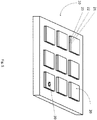
- Fig. 1 shows a schematic diagram of an embodiment of the detection device according to the invention 10.
- the detection device 10 may be installed on a satellite.
- the detection device 10 has nine planar antennas 20.
- the planar antennas 20 have on their surface a sandwich structure of two conductive layers 21, 23, which are separated by a non-conductive layer 22, on, to the two conductive layers 21, 23 electrical voltages can be applied.
- This sandwich structure represents a capacitor.
- the mechanical change of at least the outer conductive layer 21 changes the capacitance of the capacitor.
- the changing electrical parameter can also be, for example, the impedance of the planar antenna 20.
- the mechanical change of at least the outer conductive layer 21 also changes the impedance of the planar antenna 21.
- Both the capacitance changed by the impact point 30 or the resulting resonance properties of the planar antenna 20 and its impedance changed by the impact point 30 can be measured.
- By evaluating these changing electrical parameters it is possible to deduce the presence of a point of impact 30 and its size, which makes it possible to draw conclusions about the size of a space debris object and its size.
- the operation of the at least one planar antenna 20 can be switched between the functions transmit and receive on the one hand and the detection of space debris objects on the other hand.
- the planar antenna 20 fulfills the two functions of transmitting and receiving on the one hand and the detection of space debris objects on the other hand.
- a separate detection device for the detection of space debris objects is not required, but the satellite antenna anyway existing 20 can be used for the detection of space debris objects. Thus, no additional load needs to be attached to a satellite to detect space debris objects. The detection is thus possible at low cost.
Landscapes
- Engineering & Computer Science (AREA)
- Remote Sensing (AREA)
- Aviation & Aerospace Engineering (AREA)
- Geophysics And Detection Of Objects (AREA)
Abstract
Description
- Die Erfindung betrifft eine Erfassungseinrichtung für Weltraummüll, insbesondere eine Sende- und Empfangsantenne, die als Erfassungseinrichtung für Weltraummüll nutzbar ist.
- Seit Beginn der operationellen Raumfahrt mit dem Start des ersten künstlichen Erdsatelliten Sputnik 1 im Oktober 1957 wurden etliche Raketen, Satelliten, Sonden und Raumfähren in die Erdumlaufbahn geschossen. Bei jedem einzelnen Start wird Müll produziert, z.B. durch missionsbedingte Weltraummüll-Objekte, wobei der Müll in der Erdumlaufbahn auf der Höhe verbleibt, in der er mit der dort vorherrschenden Relativgeschwindigkeit fliegt. Dieser Weltraummüll gefährdet in allen Erdumlaufbahnen die Raumfahrt. Deshalb ist eine Erfassung mit allen möglichen Methoden notwendig. Am 10. Februar 2009 sind zum ersten Mal in der Geschichte der Menschheit zwei Satelliten in der Erdumlaufbahn kollidiert. Bei der Kollision handelte es sich um die beiden Kommunikationssatelliten Iridium 33 sowie den russischen Kosmos 2251, die sich über Sibirien in einer Höhe von 789 km über der Erdoberfläche befanden. Durch den gegenseitigen Aufprall, welcher mit einer Relativgeschwindigkeit von 11,6 km/s (= 41.760 km/h) erfolgte, resultierte ein Trümmerfeld, bestehend aus einer Vielzahl neu erzeugter Weltraummüll-Objekte, die größtenteils auch heute noch als Weltraummüll die Erde umkreisen.
- Teile mit einer Größe geringer als 5 cm können im Low Earth Orbit (LEO) vom Boden aus kaum geortet werden. Kollisionen von Satelliten mit Weltraummüll-Objekten mit einem Durchmesser von mehr als ca. 1 cm Durchmesser führen in der Regel zu einem vollständigen Verlust der Mission. Die Anzahl der Weltraummüll-Objekte in den Umlaufbahnen nimmt mit abnehmendem Durchmesser exponentiell zu.
- Für eine Vermessung der Weltraummüll-Objekte im Weltraum gibt es unterschiedliche Ansätze. Diese lassen sich in zerstörende und zerstörungsfreie Verfahren einteilen. Zerstörungsfreie Verfahren zeichnen sich dadurch aus, dass eine Fernerkundung des Weltraummüll-Objektes mittels eines Meßgerätes (aktive Interaktion) erfolgt. Beispielhaft können hier bodengestützte Radar- und Teleskopanlagen genannt werden, die unter anderem für eine Bahnvermessung der Weltraummüll-Objekte und somit zur Frühwarnungen eingesetzt werden. Mittels bodengestützten Anlagen lassen sich Weltraummüll-Objekte mit einem Durchmesser von ca. 10 cm im LEO und ca. 1 m im geostationären Orbit (GEO) operationell vermessen. Kleinere Weltraummüll-Objekte, z.B. mit 5 cm Durchmesser im LEO oder mit 10 cm Durchmesser im GEO, sind sporadisch detektierbar. Weltraummüll-Objekte mit einem Durchmesser kleiner 2 cm sind im LEO nicht nachweisbar. Die Erfassung von Weltraummüll mittels bodengestützter Radar- und Teleskopanlagen ist derzeit die meistgenutzte Methode. Radar- und Teleskopanlagen für die Detektion von Weltraummüll können sowohl bodengestützt als auch weltraumgestützt sein. Aktuell sind die meisten Geräte für die Detektion von Weltraummüll jedoch bodengestützt.
- Bei zerstörenden Verfahren schlägt ein zu messendes Weltraummüll-Objekt auf das Meßgerät "gewollt" ein. Zerstörende Verfahren fungieren als "In-Situ"-Meßinstrumente direkt im Orbit und liefern Meßwerte bezüglich kleiner Weltraummüll-Objekte (Durchmesser im Bereich von µm bis cm), die mittels Radar- und Teleskopanlagen nicht erfaßt werden können. Beispielhaft kann hier das am DLR-Bremen entwickelte SOLID-System genannt werden, dass die Subsysteme eines Satelliten (Solarpaneele und Lageregelungssystem) nutzt. Eine Zusammenfassung existierender In-Situ-Detektoren kann z.B. der Arbeit "Bauer, Waldemar, Space-Debris-Detektion zur Validierung von Simulations-Modellen, DLR-Forschungsbericht, 2015-08" entnommen werden. Weltraummüll-Objekte mit einem Durchmesser von ca. 1 cm sind für unbemannte Satelliten kritisch, da diese Weltraummüll-Objekte eine Mission im Falle einer Kollision mit hoher Wahrscheinlichkeit beenden. Kleinere Weltraummüll-Objekte im Millimeter-Bereich können eine Mission einschränken. Diese Weltraummüll-Objekte können die Wandung eines Satelliten durchschlagen und verwundbare Komponenten im Inneren eines Satelliten beschädigen. Weltraummüll-Objekte im Bereich µm sind beispielsweise für empfindliche Instrumente (z.B. optische Teleskope) kritisch.
- Die europäische Offenlegungsschrift
EP 2 236 422 A1 offenbart eine Erfassungsvorrichtung für einen im Weltraum fliegenden Gegenstand, die ein Erfassungsplattenelement umfasst, das in einer vorbestimmten Anordnungsteilung mehrere leitfähige Erfassungsleitungen auf einer nicht-leitfähigen Dünnschicht hält, die in einer Weltraumumgebung freigelegt werden kann. Weiterhin umfasst die Erfassungsvorrichtung eine Erfassungsschaltung, die mit jeder Erfassungsleitung verbunden ist, wobei eine Erfassung des im Weltraum fliegenden Gegenstandes, der mit dem Erfassungsplattenelement zusammengestoßen ist, durch die Erfassungsschaltung ermöglicht wird, wenn eine Erfassungsleitung auf dem Erfassungsplattenelement durch einen Zusammenstoß mit einem im Weltraum fliegenden Gegenstand unterbrochen wird. - Aus der US-amerikanischen Offenlegungsschrift
US 2012 / 0318 925 A1 ist ein Verfahren und System zur multidimensionalen Detektion einer Beschädigung einer aufblasbaren Raumplattform bekannt. Die Raumplattform weist eine äußere Struktur auf, die eine Mehrzahl von Schichten aufweist, wobei die Schichten abwechselnd Detektions- und Isolationsschichten bilden und durch eine dreidimensionale leitende Gitterstruktur miteinander verbunden sind. Die Detektionsschichten sind elektrisch leitend ausgebildet. Die Detektion einer Beschädigung basiert auf einer Änderung von durch eine Beschädigung einer oder mehreren Detektionsschicht oder Detektionsschichten oder der Gitterstruktur hervorgerufenen elektrischen Eigenschaften, wobei ein Kontrollgerät vorgesehen ist, dass dazu ausgebildet ist, eine oder mehrere Schichten oder Teile der Gitterstruktur zu deaktivieren. - Aus der US-amerikanischen Offenlegungsschrift
US 2012 / 0188078 A1 ist ein Schadenserkennungs- und -sanierungssystem für ein Objekt bekannt. Zur Schadenserkennung weist das Schadenserkennungssystem eine erste Schicht auf, die elektrisch leitfähige Leiter auf einem nichtleitenden Substrat aufweist, wobei durch die elektrisch leitfähigen Leiter ein elektromagnetisches Signal von einem Eingangskopplungspunkt zu einem Ausgangskopplungspunkt leitbar ist. Ein Schaden wird durch den Vergleich des elektromagnetischen Signals von dem Eingangskopplungspunkt zu dem Ausgangskopplungspunkt erkannt. - Aus der japanischen Offenlegungsschrift
JP 2012 - 116349 A - Aus der internationalen Anmeldung
2016 / 164 758 A1 - Allen bekannten System ist gemeinsam, dass sie hohe Kosten verursachen und größtenteils nicht in der Lage sind, kleinste Partikel zu erfassen. Heutige Vorhersagen basieren auf Simulations-Modellen, die kaum Meßwerte zur Validierung verwenden.
- Aufgabe der Erfindung ist es, eine auf einem künstlichen Weltraumflugkörper installierbare Erfassungseinrichtung für die Erfassung von Weltraummüll-Objekten anzugeben, dass in der Lage ist, kleinste Partikel bis in den µm-Bereich zu erfassen, kostengünstig ist und keine zusätzliche Last einem im Weltraum fliegenden Objekts hinzufügt.
- Erfindungsgemäß wird diese Aufgabe durch eine Erfassungseinrichtung mit den Merkmalen des unabhängigen Anspruches 1 gelöst. Vorteilhafte Weiterbildungen der Erfassungseinrichtung ergeben sich aus den Unteransprüchen 2 bis 7.
- Eine erfindungsgemäße Erfassungseinrichtung weist mindestens eine Planarantenne auf, wobei unter Planarantenne jede flächige Antenne verstanden wird. Es ist nicht erforderlich, dass die flächige Antenne absolut eben ist. Auch werden im Wesentlichen flächige Antennen mit einer Oberflächenstruktur unter dem Begriff Planarantenne verstanden. Die Planarantenne weist an ihrer Oberfläche eine Sandwichstruktur aus zwei leitfähigen Schichten, die durch eine nicht leitfähige Schicht getrennt sind, auf, wobei an die zwei leitfähigen Schichten elektrische Spannungen anlegbar sind und zumindest die äußere leitfähige Schicht durch den Aufprall eines Weltraummüll-Objekts mechanisch veränderbar ist. In einer vorteilhaften Ausführungsform ist die äußere leitfähige Schicht der Planarantenne durch den Aufprall eines Weltraummüll-Objekts deformierbar. Durch die mechanischen Veränderung zumindest der äußeren leitfähigen Schicht verändert sich zumindest ein elektrischer Parameter der Planarantenne, wobei dieser Parameter messbar ist und aus dessen Veränderung auf das Auftreffen eines Weltraummüll-Objektes und auf die Größe des aufprallenden Weltraummüll-Objektes geschlossen werden kann.
- Die Sandwichstruktur aus zwei leitfähigen Schichten, die durch eine nicht leitfähige Schicht getrennt sind, stellt einen Kondensator dar. Der sich ändernde elektrische Parameter kann beispielsweise die Kapazität des Kondensators sein. Durch die mechanischen Veränderung zumindest der äußeren leitfähigen Schicht ändert sich die Kapazität des Kondensators. Der sich ändernde elektrische Parameter kann beispielsweise auch die Impedanz der Planarantenne sein. Durch die mechanische Veränderung zumindest der äußeren leitfähigen Schicht ändert sich auch die Impedanz der Planarantenne.
- Die als Kondensator wirkende Sandwichstruktur der Planarantenne kann mit einer Spule zu einem elektrischen Schwingkreis verbunden werden. Bei diesem Schwingkreis wird Energie zwischen dem magnetischen Feld der Spule und dem elektrischen Feld des Kondensators periodisch mit einer bestimmten Frequenz ausgetauscht, wodurch abwechselnd hohe Stromstärke oder hohe Spannung vorliegen. Wird ein solcher Schwingkreis durch einen Impuls periodisch angestoßen, dann führt er periodische erzwungene Schwingungen aus, deren Frequenz identisch mit der Erregerfrequenz ist. Dabei treten Resonanzerscheinungen auf. Die Resonanzerscheinungen können erfaßt werden und aus der Veränderung der erfassten Resonanzerscheinungen kann auf das Auftreffen eines Weltraummüll-Objekts und auf die Stärke des Aufpralls des Weltraummüll-Objekts auf die Planarantenne geschlossen werden. Trifft ein Weltraummüll-Objekt auf die Oberfläche der Planarantenne, so wird zumindest die oberste leitfähige Schicht der Sandwichstruktur mechanisch verändert, beispielsweise deformiert. Durch den damit veränderten Abstand der beiden als Elektroden dienenden leitfähigen Schichten der Sandwichstruktur ändert sich die Kapazität. Weiterhin ändert sich die Resonanzfrequenz des Schwingkreises. Aus der Größe dieser Änderungen lässt sich beispielsweise über eine inverse Fourieranalyse beispielsweise im Zeit- oder Frequenzbereich auf die Größe des auftreffenden Weltraummüll-Objekts schließen.
- Alternativ oder zusätzlich kann auch die Impedanz der Planarantenne erfaßt werden. Durch die mechanische Veränderung, beispielsweise eine Deformation, zumindest der äußeren leitfähigen Schicht der Planarantenne ändert sich auch deren Impedanz. Aus der Veränderung der erfassten Impedanzen kann ebenfalls auf das Auftreffen eines Weltraummüll-Objekts und auf die Stärke des Aufpralls des Weltraummüll-Objekts auf die Planarantenne geschlossen werden.
- Der Betrieb der mindestens einen Planarantenne kann zwischen den Funktionen Senden und Empfangen einerseits und der Detektion von Weltraummüll-Objekten andererseits umgeschaltet werden. Dadurch erfüllt die Planarantenne die beiden Funktionen Senden und Empfangen einerseits und der Detektion von Weltraummüll-Objekten andererseits. Eine eigene Erfassungseinrichtung für die Erfassung von Weltraummüll-Objekten ist nicht erforderlich, sondern die an Satelliten ohnehin vorhandene Planarantenne kann für die Erfassung von Weltraummüll-Objekten genutzt werden. Somit braucht keine zusätzliche Last an einem Satelliten angebracht werden, um Weltraummüll-Objekte zu erfassen. Die Erfassung ist somit kostengünstig möglich.
- In einer vorteilhaften Ausführungsform weist die mindestens eine Planarantenne nur einen Port, also nur einen Ein- beziehungsweise Ausgang, auf. Beispielsweise kann die Planarantenne eine planare Patchantenne sein, die beispielsweise aus einer rechteckigen Metallfläche besteht. Diese Metallfläche kann als Resonator wirken.
- Alternativ kann die mindestens eine Planarantenne mindestens zwei Ports aufweisen, wobei alle Ports bis auf einen mit einem Abschlusswiderstand terminiert sind. Beispielsweise kann die mindestens eine Planarantenne eine travelling-wave Antenne sein, bei der sich der die Funkwellen erzeugende Hochfrequenzstrom nur in einer Richtung durch die Antenne bewegt. Dabei sind in einer Ausführungsform mindestens zwei Ports mit einem Mess-/Sendesystem verbunden.
- Es hat sich als vorteilhaft erwiesen, wenn die Erfassungseinrichtung mehrere Planarantennen aufweist, die als Array zusammengefasst sind. In einem aus einer Anzahl von Einzelstrahlern konstruierten Antennenarray überlagern sich die von den Einzelstrahlern abgestrahlten Felder und formen durch konstruktive Interferenz ein gemeinsames Antennendiagramm.
- Mit der erfinderischen Erfassungseinrichtung können kleinste Partikel von wenigen µm von Weltraummüll-Objekten mit Hilfe von an Satelliten angebrachten Planarantennen detektiert werden, ohne dass die Hauptfunktionen dieser Antennen eingeschränkt wird. Mit der Erfassungseinrichtung ist es möglich, neben der eigentlichen Aufgabe der Antenne, Signale zu empfangen und zu senden, zusätzliche Erkenntnisse über Weltraummüll-Objekte zu gewinnen. Mit diesem "Dual-use"-Prinzip ist eine kostengünstige Forschung über auch kleinste Weltraummüll-Objekte realisierbar, ohne dass eine flächenintensive Primärnutzlast auf einem Satelliten oder Raumfahrzeug integriert werden muss.
- Weitere Vorteile, Besonderheiten und zweckmäßige Weiterbildungen der Erfindung ergeben sich aus den Unteransprüchen und der nachfolgenden Darstellung eines bevorzugten Ausführungsbeispiels anhand der Abbildung.
- Die Abbildung zeigt:
-
Fig. 1 Prinzipskizze einer Ausführungsform der erfindungsgemäßen Erfassungseinrichtung 10 -
Fig. 1 zeigt eine Prinzipskizze einer Ausführungsform der erfindungsgemäßen Erfassungseinrichtung 10. Die Erfassungseinrichtung 10 kann auf einem Satelliten installiert sein. Die Erfassungseinrichtung 10 weist neun Planarantennen 20 auf. Die Planarantennen 20 weisen an ihrer Oberfläche eine Sandwichstruktur aus zwei leitfähigen Schichten 21, 23, die durch eine nicht leitfähige Schicht 22 getrennt sind, auf, wobei an die zwei leitfähigen Schichten 21, 23 elektrische Spannungen anlegbar sind. Diese Sandwichstruktur stellt einen Kondensator dar. Trifft ein Weltraummüll-Objekt auf die äußere leitfähige Schicht 21, so wird diese an der Einschlagstelle 30 mechanisch deformiert. Durch die Deformation zumindest der äußeren leitfähigen Schicht 21 verändert sich zumindest ein elektrischer Parameter der Planarantenne 20. Der sich ändernde elektrische Parameter kann beispielsweise die Kapazität des Kondensators sein. Durch die mechanischen Veränderung zumindest der äußeren leitfähigen Schicht 21 ändert sich die Kapazität des Kondensators. Der sich ändernde elektrische Parameter kann beispielsweise auch die Impedanz der Planarantenne 20 sein. Durch die mechanische Veränderung zumindest der äußeren leitfähigen Schicht 21 ändert sich auch die Impedanz der Planarantenne 21. - Sowohl die sich durch die Einschlagstelle 30 veränderte Kapazität beziehungsweise die dadurch sich ändernden Resonanzeigenschaften der Planarantenne 20 als auch ihre sich durch die Einschlagstelle 30 veränderte Impedanz kann gemessen werden. Durch eine Auswertung dieser sich ändernden elektrischen Parameter kann auf das Vorhandensein einer Einschlagstelle 30 und ihre Größe geschlossen werden, wodurch ein Rückschluss auf das Auftreffen eines Weltraummüll-Objekts und dessen Größe möglich ist.
- Der Betrieb der mindestens einen Planarantenne 20 kann zwischen den Funktionen Senden und Empfangen einerseits und der Detektion von Weltraummüll-Objekten andererseits umgeschaltet werden. Dadurch erfüllt die Planarantenne 20 die beiden Funktionen Senden und Empfangen einerseits und der Detektion von Weltraummüll-Objekten andererseits. Eine eigene Erfassungseinrichtung für die Erfassung von Weltraummüll-Objekten ist nicht erforderlich, sondern die an Satelliten ohnehin vorhandene Planarantenne 20 kann für die Erfassung von Weltraummüll-Objekten genutzt werden. Somit braucht keine zusätzliche Last an einem Satelliten angebracht werden, um Weltraummüll-Objekte zu erfassen. Die Erfassung ist somit kostengünstig möglich.
- Die hier gezeigten Ausführungsformen stellen nur Beispiele für die vorliegende Erfindung dar und dürfen daher nicht einschränkend verstanden werden. Alternative durch den Fachmann in Erwägung gezogene Ausführungsformen sind gleichermaßen vom Schutzbereich der vorliegenden Erfindung umfasst.
-
- 10
- Erfassungseinrichtung, Antennenarray
- 20
- Planarantenne
- 21
- äußere leitfähige Schicht
- 22
- nicht leitfähige Schicht
- 23
- innere leitfähige Schicht
- 30
- Einschlagstelle
Claims (7)
- Erfassungseinrichtung (10) für die Erfassung von Weltraummüll-Objekten im Weltraum, wobei der Aufprall eines Weltraummüll-Objekts auf der Erfassungseinrichtung (10) detektierbar ist,
dadurch gekennzeichnet,
dass die Erfassungseinrichtung (10) mindestens eine Planarantenne (20) aufweist, wobei die Planarantenne (20) an ihrer Oberfläche eine Sandwichstruktur aus zwei leitfähigen Schichten (21, 23), die durch eine nicht leitfähige Schicht (22) getrennt sind, aufweist, wobei an die zwei leitfähigen Schichten (21, 23) elektrische Spannungen anlegbar sind und zumindest die äußere leitfähige Schicht (21) durch den Aufprall eines Weltraummüll-Objekts mechanisch veränderbar ist, wobei sich durch die mechanische Veränderung zumindest der äußeren leitfähigen Schicht zumindest einer ihrer elektrischen Parameter verändert, wobei diese Veränderung messbar ist und wobei aus dieser Veränderung auf das Auftreffen eines Weltraummüll-Objekts schließbar ist. - Erfassungseinrichtung (10) gemäß Anspruch 1,
dadurch gekennzeichnet,
dass zumindest die äußere leitfähige Schicht (21) durch den Aufprall eines Weltraummüll-Objekts deformierbar ist. - Erfassungseinrichtung (10) gemäß Anspruch 1 oder 2,
dadurch gekennzeichnet,
dass mindestens ein elektrischer Parameter mit der mechanischen Veränderung der äußeren leitfähigen Schicht (21) veränderbar ist. - Erfassungseinrichtung (10) gemäß einem der vorherigen Ansprüche,
dadurch gekennzeichnet,
dass die mindestens eine Planarantenne (20) nur einen Port aufweist. - Erfassungseinrichtung (10) gemäß einem der Ansprüche 1 bis 3,
dadurch gekennzeichnet,
dass die mindestens eine Planarantenne (20) mindestens zwei Ports aufweist, wobei alle Ports bis auf einen mit einem Abschlusswiderstand terminiert sind. - Erfassungseinrichtung (10) gemäß Anspruch 5,
dadurch gekennzeichnet,
dass mindestens zwei Ports mit einem Mess-/Sendesystem verbunden sind. - Erfassungseinrichtung (10) gemäß einem der vorherigen Ansprüche,
dadurch gekennzeichnet,
dass die Erfassungseinrichtung (10) mehrere Planarantennen (20) aufweist, wobei die mehreren Planarantennen (20) als Array zusammengefasst sind.
Applications Claiming Priority (1)
| Application Number | Priority Date | Filing Date | Title |
|---|---|---|---|
| DE102016125874.1A DE102016125874B3 (de) | 2016-12-29 | 2016-12-29 | Erfassungseinrichtung |
Publications (2)
| Publication Number | Publication Date |
|---|---|
| EP3345841A1 true EP3345841A1 (de) | 2018-07-11 |
| EP3345841B1 EP3345841B1 (de) | 2019-10-09 |
Family
ID=60781711
Family Applications (1)
| Application Number | Title | Priority Date | Filing Date |
|---|---|---|---|
| EP17208322.2A Active EP3345841B1 (de) | 2016-12-29 | 2017-12-19 | Erfassungseinrichtung |
Country Status (2)
| Country | Link |
|---|---|
| EP (1) | EP3345841B1 (de) |
| DE (1) | DE102016125874B3 (de) |
Cited By (1)
| Publication number | Priority date | Publication date | Assignee | Title |
|---|---|---|---|---|
| CN111595738A (zh) * | 2020-06-03 | 2020-08-28 | 北京卫星环境工程研究所 | 超高速颗粒直径分布探测装置 |
Citations (7)
| Publication number | Priority date | Publication date | Assignee | Title |
|---|---|---|---|---|
| US5608414A (en) * | 1995-06-30 | 1997-03-04 | Martin Marietta Corp. | Heat rejecting spacecraft array antenna |
| JPH11227699A (ja) * | 1998-02-17 | 1999-08-24 | Ishikawajima Harima Heavy Ind Co Ltd | 宇宙漂流物体の捕獲装置 |
| EP2236422A1 (de) | 2008-01-17 | 2010-10-06 | IHI Corporation | Vorrichtung zur erkennung von im raum schwebenden stoffen |
| JP2012116349A (ja) | 2010-12-01 | 2012-06-21 | Ihi Corp | 宇宙浮遊物体検出装置 |
| US20120188078A1 (en) | 2011-01-21 | 2012-07-26 | Soles Alexander M | Damage detection and remediation system and methods thereof |
| US20120318925A1 (en) | 2011-06-16 | 2012-12-20 | Space Administration | Multi-Dimensional Damage Detection |
| WO2016164758A1 (en) | 2015-04-08 | 2016-10-13 | Sri International | 1d phased array antenna for radar and communications |
-
2016
- 2016-12-29 DE DE102016125874.1A patent/DE102016125874B3/de active Active
-
2017
- 2017-12-19 EP EP17208322.2A patent/EP3345841B1/de active Active
Patent Citations (7)
| Publication number | Priority date | Publication date | Assignee | Title |
|---|---|---|---|---|
| US5608414A (en) * | 1995-06-30 | 1997-03-04 | Martin Marietta Corp. | Heat rejecting spacecraft array antenna |
| JPH11227699A (ja) * | 1998-02-17 | 1999-08-24 | Ishikawajima Harima Heavy Ind Co Ltd | 宇宙漂流物体の捕獲装置 |
| EP2236422A1 (de) | 2008-01-17 | 2010-10-06 | IHI Corporation | Vorrichtung zur erkennung von im raum schwebenden stoffen |
| JP2012116349A (ja) | 2010-12-01 | 2012-06-21 | Ihi Corp | 宇宙浮遊物体検出装置 |
| US20120188078A1 (en) | 2011-01-21 | 2012-07-26 | Soles Alexander M | Damage detection and remediation system and methods thereof |
| US20120318925A1 (en) | 2011-06-16 | 2012-12-20 | Space Administration | Multi-Dimensional Damage Detection |
| WO2016164758A1 (en) | 2015-04-08 | 2016-10-13 | Sri International | 1d phased array antenna for radar and communications |
Non-Patent Citations (2)
| Title |
|---|
| BAUER WALDEMAR ET AL: "Development of in-situ Space Debris Detector", ADVANCES IN SPACE RESEARCH, ELSEVIER, AMSTERDAM, NL, vol. 54, no. 9, 7 August 2014 (2014-08-07), pages 1858 - 1869, XP029049115, ISSN: 0273-1177, DOI: 10.1016/J.ASR.2014.07.035 * |
| KASSEL P C ET AL: "METAL-OXIDE SILICON CAPACITOR DETECTORS FOR MEASURING MICROMETEROROID AND SPACE-DEBRIS FLUX", JOURNAL OF SPACECRAFT AND ROCKETS, AMERICAN INSTITUTE OF AERONAUTICS AND ASTRONAUTICS,REASTON,VA, US, vol. 32, no. 4, 1 July 1995 (1995-07-01), pages 710 - 718, XP000523499, ISSN: 0022-4650 * |
Cited By (2)
| Publication number | Priority date | Publication date | Assignee | Title |
|---|---|---|---|---|
| CN111595738A (zh) * | 2020-06-03 | 2020-08-28 | 北京卫星环境工程研究所 | 超高速颗粒直径分布探测装置 |
| CN111595738B (zh) * | 2020-06-03 | 2022-08-23 | 北京卫星环境工程研究所 | 超高速颗粒直径分布探测装置 |
Also Published As
| Publication number | Publication date |
|---|---|
| EP3345841B1 (de) | 2019-10-09 |
| DE102016125874B3 (de) | 2018-02-15 |
Similar Documents
| Publication | Publication Date | Title |
|---|---|---|
| EP3345840B1 (de) | Erfassungssystem | |
| DE3222869C1 (de) | Vorrichtung zur Erzeugung kuenstlicher Zielmarken in der Abbildung eines Radars mit synthetischer Apertur | |
| DE69713897T2 (de) | Impedanzmessgerät für resonanzstruktur | |
| DE10120536C2 (de) | Radarsystem zur aktiven Hinderniswarnung und Abbildung der Erdoberfläche | |
| EP3345841B1 (de) | Erfassungseinrichtung | |
| DE102012006155A1 (de) | Sensoreinrichtung und Verfahren zur Detektierung und Lokalisierung von Rissen in Bauteilen | |
| EP1145038B1 (de) | Anordnung zur interferometrischen radarmessung nach dem rosar-prinzip | |
| DE102020126431A1 (de) | Verfahren zur Detektion eines mit Flächenelementen aus Metamaterial oder "frequency selective surfaces" - Materialien ausgestatteten Flugkörpers | |
| US6154167A (en) | Excitation method and ultra-wide bandwidth antenna for ground penetrating radar systems | |
| EP2983008B1 (de) | Sensorvorrichtung mit kombiniertem ultraschallsensor und radarsensor zum erfassen eines objekts in einem umfeld eines kraftfahrzeugs und kraftfahrzeug | |
| EP3277060B1 (de) | Mikroelektronisches modul zur veränderung der elektromagnetischen signatur einer oberfläche, modularray und verfahren zur veränderung der elektromagnetischen signatur einer oberfläche | |
| EP2133710B1 (de) | Verfahren zum Testen eines Transponders für den Flugfunk und Messsystem | |
| DE102010034065A1 (de) | Verfahren und System zum Nachführen zweier Kommunikationsteilnehmer eines optischen Satelliten-Kommunikationssystems | |
| DE102023209060A1 (de) | Ultraschall-Phasenarray-Sensor | |
| EP2656528B1 (de) | Verfahren zum betreiben eines elektronischen aufklärungssystems in einer durch einen störsender geschützten umgebung | |
| DE102021203826A1 (de) | HPEM-Detektor | |
| Brookner | Never ending saga of phased array breakthroughs | |
| DE3315499C2 (de) | ||
| DE102021212390A1 (de) | Radarvorrichtung und Radarverfahren | |
| EP3529862B1 (de) | Vorrichtung und verfahren zur niederschlagsmessung | |
| Hu et al. | Insect speed extraction method based on a high resolution and full polarisation radar with vertical‐looking mode | |
| DE102016224962B3 (de) | Synthetik-Apertur-Radarverfahren und Synthetik-Apertur-Radarsystem | |
| EP2124405B1 (de) | Anordnung und verfahren zur drahtlosen übertragung von phasenkritischen signalen bei variabler längenänderung der übertragungsstrecke | |
| DE102013013123A1 (de) | Vorrichtung und Verfahren zur Ortung von Funksignalen mittels Doppler-Effekt an Bord von fliegenden Plattformen | |
| Varadan et al. | Smart electronics and sensors for IVHS and automobile collision warning antenna systems |
Legal Events
| Date | Code | Title | Description |
|---|---|---|---|
| PUAI | Public reference made under article 153(3) epc to a published international application that has entered the european phase |
Free format text: ORIGINAL CODE: 0009012 |
|
| STAA | Information on the status of an ep patent application or granted ep patent |
Free format text: STATUS: THE APPLICATION HAS BEEN PUBLISHED |
|
| AK | Designated contracting states |
Kind code of ref document: A1 Designated state(s): AL AT BE BG CH CY CZ DE DK EE ES FI FR GB GR HR HU IE IS IT LI LT LU LV MC MK MT NL NO PL PT RO RS SE SI SK SM TR |
|
| AX | Request for extension of the european patent |
Extension state: BA ME |
|
| STAA | Information on the status of an ep patent application or granted ep patent |
Free format text: STATUS: REQUEST FOR EXAMINATION WAS MADE |
|
| 17P | Request for examination filed |
Effective date: 20190107 |
|
| RBV | Designated contracting states (corrected) |
Designated state(s): AL AT BE BG CH CY CZ DE DK EE ES FI FR GB GR HR HU IE IS IT LI LT LU LV MC MK MT NL NO PL PT RO RS SE SI SK SM TR |
|
| GRAP | Despatch of communication of intention to grant a patent |
Free format text: ORIGINAL CODE: EPIDOSNIGR1 |
|
| STAA | Information on the status of an ep patent application or granted ep patent |
Free format text: STATUS: GRANT OF PATENT IS INTENDED |
|
| INTG | Intention to grant announced |
Effective date: 20190423 |
|
| GRAS | Grant fee paid |
Free format text: ORIGINAL CODE: EPIDOSNIGR3 |
|
| GRAA | (expected) grant |
Free format text: ORIGINAL CODE: 0009210 |
|
| STAA | Information on the status of an ep patent application or granted ep patent |
Free format text: STATUS: THE PATENT HAS BEEN GRANTED |
|
| AK | Designated contracting states |
Kind code of ref document: B1 Designated state(s): AL AT BE BG CH CY CZ DE DK EE ES FI FR GB GR HR HU IE IS IT LI LT LU LV MC MK MT NL NO PL PT RO RS SE SI SK SM TR |
|
| REG | Reference to a national code |
Ref country code: GB Ref legal event code: FG4D Free format text: NOT ENGLISH |
|
| REG | Reference to a national code |
Ref country code: CH Ref legal event code: EP |
|
| REG | Reference to a national code |
Ref country code: DE Ref legal event code: R096 Ref document number: 502017002519 Country of ref document: DE |
|
| REG | Reference to a national code |
Ref country code: IE Ref legal event code: FG4D Free format text: LANGUAGE OF EP DOCUMENT: GERMAN |
|
| REG | Reference to a national code |
Ref country code: AT Ref legal event code: REF Ref document number: 1188520 Country of ref document: AT Kind code of ref document: T Effective date: 20191115 |
|
| REG | Reference to a national code |
Ref country code: NL Ref legal event code: MP Effective date: 20191009 |
|
| REG | Reference to a national code |
Ref country code: LT Ref legal event code: MG4D |
|
| PG25 | Lapsed in a contracting state [announced via postgrant information from national office to epo] |
Ref country code: PT Free format text: LAPSE BECAUSE OF FAILURE TO SUBMIT A TRANSLATION OF THE DESCRIPTION OR TO PAY THE FEE WITHIN THE PRESCRIBED TIME-LIMIT Effective date: 20200210 Ref country code: ES Free format text: LAPSE BECAUSE OF FAILURE TO SUBMIT A TRANSLATION OF THE DESCRIPTION OR TO PAY THE FEE WITHIN THE PRESCRIBED TIME-LIMIT Effective date: 20191009 Ref country code: LV Free format text: LAPSE BECAUSE OF FAILURE TO SUBMIT A TRANSLATION OF THE DESCRIPTION OR TO PAY THE FEE WITHIN THE PRESCRIBED TIME-LIMIT Effective date: 20191009 Ref country code: SE Free format text: LAPSE BECAUSE OF FAILURE TO SUBMIT A TRANSLATION OF THE DESCRIPTION OR TO PAY THE FEE WITHIN THE PRESCRIBED TIME-LIMIT Effective date: 20191009 Ref country code: NL Free format text: LAPSE BECAUSE OF FAILURE TO SUBMIT A TRANSLATION OF THE DESCRIPTION OR TO PAY THE FEE WITHIN THE PRESCRIBED TIME-LIMIT Effective date: 20191009 Ref country code: GR Free format text: LAPSE BECAUSE OF FAILURE TO SUBMIT A TRANSLATION OF THE DESCRIPTION OR TO PAY THE FEE WITHIN THE PRESCRIBED TIME-LIMIT Effective date: 20200110 Ref country code: BG Free format text: LAPSE BECAUSE OF FAILURE TO SUBMIT A TRANSLATION OF THE DESCRIPTION OR TO PAY THE FEE WITHIN THE PRESCRIBED TIME-LIMIT Effective date: 20200109 Ref country code: FI Free format text: LAPSE BECAUSE OF FAILURE TO SUBMIT A TRANSLATION OF THE DESCRIPTION OR TO PAY THE FEE WITHIN THE PRESCRIBED TIME-LIMIT Effective date: 20191009 Ref country code: LT Free format text: LAPSE BECAUSE OF FAILURE TO SUBMIT A TRANSLATION OF THE DESCRIPTION OR TO PAY THE FEE WITHIN THE PRESCRIBED TIME-LIMIT Effective date: 20191009 Ref country code: NO Free format text: LAPSE BECAUSE OF FAILURE TO SUBMIT A TRANSLATION OF THE DESCRIPTION OR TO PAY THE FEE WITHIN THE PRESCRIBED TIME-LIMIT Effective date: 20200109 Ref country code: PL Free format text: LAPSE BECAUSE OF FAILURE TO SUBMIT A TRANSLATION OF THE DESCRIPTION OR TO PAY THE FEE WITHIN THE PRESCRIBED TIME-LIMIT Effective date: 20191009 |
|
| PG25 | Lapsed in a contracting state [announced via postgrant information from national office to epo] |
Ref country code: RS Free format text: LAPSE BECAUSE OF FAILURE TO SUBMIT A TRANSLATION OF THE DESCRIPTION OR TO PAY THE FEE WITHIN THE PRESCRIBED TIME-LIMIT Effective date: 20191009 Ref country code: HR Free format text: LAPSE BECAUSE OF FAILURE TO SUBMIT A TRANSLATION OF THE DESCRIPTION OR TO PAY THE FEE WITHIN THE PRESCRIBED TIME-LIMIT Effective date: 20191009 Ref country code: IS Free format text: LAPSE BECAUSE OF FAILURE TO SUBMIT A TRANSLATION OF THE DESCRIPTION OR TO PAY THE FEE WITHIN THE PRESCRIBED TIME-LIMIT Effective date: 20200224 |
|
| PG25 | Lapsed in a contracting state [announced via postgrant information from national office to epo] |
Ref country code: AL Free format text: LAPSE BECAUSE OF FAILURE TO SUBMIT A TRANSLATION OF THE DESCRIPTION OR TO PAY THE FEE WITHIN THE PRESCRIBED TIME-LIMIT Effective date: 20191009 |
|
| REG | Reference to a national code |
Ref country code: DE Ref legal event code: R119 Ref document number: 502017002519 Country of ref document: DE |
|
| PG2D | Information on lapse in contracting state deleted |
Ref country code: IS |
|
| PG25 | Lapsed in a contracting state [announced via postgrant information from national office to epo] |
Ref country code: RO Free format text: LAPSE BECAUSE OF FAILURE TO SUBMIT A TRANSLATION OF THE DESCRIPTION OR TO PAY THE FEE WITHIN THE PRESCRIBED TIME-LIMIT Effective date: 20191009 Ref country code: CZ Free format text: LAPSE BECAUSE OF FAILURE TO SUBMIT A TRANSLATION OF THE DESCRIPTION OR TO PAY THE FEE WITHIN THE PRESCRIBED TIME-LIMIT Effective date: 20191009 Ref country code: EE Free format text: LAPSE BECAUSE OF FAILURE TO SUBMIT A TRANSLATION OF THE DESCRIPTION OR TO PAY THE FEE WITHIN THE PRESCRIBED TIME-LIMIT Effective date: 20191009 Ref country code: DK Free format text: LAPSE BECAUSE OF FAILURE TO SUBMIT A TRANSLATION OF THE DESCRIPTION OR TO PAY THE FEE WITHIN THE PRESCRIBED TIME-LIMIT Effective date: 20191009 Ref country code: IS Free format text: LAPSE BECAUSE OF FAILURE TO SUBMIT A TRANSLATION OF THE DESCRIPTION OR TO PAY THE FEE WITHIN THE PRESCRIBED TIME-LIMIT Effective date: 20200209 |
|
| PLBE | No opposition filed within time limit |
Free format text: ORIGINAL CODE: 0009261 |
|
| STAA | Information on the status of an ep patent application or granted ep patent |
Free format text: STATUS: NO OPPOSITION FILED WITHIN TIME LIMIT |
|
| REG | Reference to a national code |
Ref country code: BE Ref legal event code: MM Effective date: 20191231 |
|
| PG25 | Lapsed in a contracting state [announced via postgrant information from national office to epo] |
Ref country code: SM Free format text: LAPSE BECAUSE OF FAILURE TO SUBMIT A TRANSLATION OF THE DESCRIPTION OR TO PAY THE FEE WITHIN THE PRESCRIBED TIME-LIMIT Effective date: 20191009 Ref country code: SK Free format text: LAPSE BECAUSE OF FAILURE TO SUBMIT A TRANSLATION OF THE DESCRIPTION OR TO PAY THE FEE WITHIN THE PRESCRIBED TIME-LIMIT Effective date: 20191009 Ref country code: MC Free format text: LAPSE BECAUSE OF FAILURE TO SUBMIT A TRANSLATION OF THE DESCRIPTION OR TO PAY THE FEE WITHIN THE PRESCRIBED TIME-LIMIT Effective date: 20191009 Ref country code: IT Free format text: LAPSE BECAUSE OF FAILURE TO SUBMIT A TRANSLATION OF THE DESCRIPTION OR TO PAY THE FEE WITHIN THE PRESCRIBED TIME-LIMIT Effective date: 20191009 |
|
| 26N | No opposition filed |
Effective date: 20200710 |
|
| PG25 | Lapsed in a contracting state [announced via postgrant information from national office to epo] |
Ref country code: IE Free format text: LAPSE BECAUSE OF NON-PAYMENT OF DUE FEES Effective date: 20191219 Ref country code: DE Free format text: LAPSE BECAUSE OF NON-PAYMENT OF DUE FEES Effective date: 20200701 |
|
| PG25 | Lapsed in a contracting state [announced via postgrant information from national office to epo] |
Ref country code: SI Free format text: LAPSE BECAUSE OF FAILURE TO SUBMIT A TRANSLATION OF THE DESCRIPTION OR TO PAY THE FEE WITHIN THE PRESCRIBED TIME-LIMIT Effective date: 20191009 Ref country code: BE Free format text: LAPSE BECAUSE OF NON-PAYMENT OF DUE FEES Effective date: 20191231 |
|
| PG25 | Lapsed in a contracting state [announced via postgrant information from national office to epo] |
Ref country code: CY Free format text: LAPSE BECAUSE OF FAILURE TO SUBMIT A TRANSLATION OF THE DESCRIPTION OR TO PAY THE FEE WITHIN THE PRESCRIBED TIME-LIMIT Effective date: 20191009 |
|
| PG25 | Lapsed in a contracting state [announced via postgrant information from national office to epo] |
Ref country code: MT Free format text: LAPSE BECAUSE OF FAILURE TO SUBMIT A TRANSLATION OF THE DESCRIPTION OR TO PAY THE FEE WITHIN THE PRESCRIBED TIME-LIMIT Effective date: 20191009 Ref country code: HU Free format text: LAPSE BECAUSE OF FAILURE TO SUBMIT A TRANSLATION OF THE DESCRIPTION OR TO PAY THE FEE WITHIN THE PRESCRIBED TIME-LIMIT; INVALID AB INITIO Effective date: 20171219 |
|
| REG | Reference to a national code |
Ref country code: CH Ref legal event code: PL |
|
| PG25 | Lapsed in a contracting state [announced via postgrant information from national office to epo] |
Ref country code: CH Free format text: LAPSE BECAUSE OF NON-PAYMENT OF DUE FEES Effective date: 20201231 Ref country code: LI Free format text: LAPSE BECAUSE OF NON-PAYMENT OF DUE FEES Effective date: 20201231 |
|
| PG25 | Lapsed in a contracting state [announced via postgrant information from national office to epo] |
Ref country code: TR Free format text: LAPSE BECAUSE OF FAILURE TO SUBMIT A TRANSLATION OF THE DESCRIPTION OR TO PAY THE FEE WITHIN THE PRESCRIBED TIME-LIMIT Effective date: 20191009 |
|
| PG25 | Lapsed in a contracting state [announced via postgrant information from national office to epo] |
Ref country code: MK Free format text: LAPSE BECAUSE OF FAILURE TO SUBMIT A TRANSLATION OF THE DESCRIPTION OR TO PAY THE FEE WITHIN THE PRESCRIBED TIME-LIMIT Effective date: 20191009 |
|
| REG | Reference to a national code |
Ref country code: AT Ref legal event code: MM01 Ref document number: 1188520 Country of ref document: AT Kind code of ref document: T Effective date: 20221219 |
|
| PG25 | Lapsed in a contracting state [announced via postgrant information from national office to epo] |
Ref country code: AT Free format text: LAPSE BECAUSE OF NON-PAYMENT OF DUE FEES Effective date: 20221219 |
|
| PG25 | Lapsed in a contracting state [announced via postgrant information from national office to epo] |
Ref country code: AT Free format text: LAPSE BECAUSE OF NON-PAYMENT OF DUE FEES Effective date: 20221219 |
|
| PGFP | Annual fee paid to national office [announced via postgrant information from national office to epo] |
Ref country code: LU Payment date: 20251112 Year of fee payment: 9 |
|
| PGFP | Annual fee paid to national office [announced via postgrant information from national office to epo] |
Ref country code: GB Payment date: 20251113 Year of fee payment: 9 |
|
| PGFP | Annual fee paid to national office [announced via postgrant information from national office to epo] |
Ref country code: FR Payment date: 20251111 Year of fee payment: 9 |
|
| PGFP | Annual fee paid to national office [announced via postgrant information from national office to epo] |
Ref country code: AT Payment date: 20260410 Year of fee payment: 5 |