EP3345794B1 - Airbag arrangement and method for manufacturing the same - Google Patents
Airbag arrangement and method for manufacturing the same Download PDFInfo
- Publication number
- EP3345794B1 EP3345794B1 EP17209724.8A EP17209724A EP3345794B1 EP 3345794 B1 EP3345794 B1 EP 3345794B1 EP 17209724 A EP17209724 A EP 17209724A EP 3345794 B1 EP3345794 B1 EP 3345794B1
- Authority
- EP
- European Patent Office
- Prior art keywords
- wall
- material web
- airbag
- chute
- flap
- Prior art date
- Legal status (The legal status is an assumption and is not a legal conclusion. Google has not performed a legal analysis and makes no representation as to the accuracy of the status listed.)
- Active
Links
Images


Classifications
-
- B—PERFORMING OPERATIONS; TRANSPORTING
- B60—VEHICLES IN GENERAL
- B60R—VEHICLES, VEHICLE FITTINGS, OR VEHICLE PARTS, NOT OTHERWISE PROVIDED FOR
- B60R21/00—Arrangements or fittings on vehicles for protecting or preventing injuries to occupants or pedestrians in case of accidents or other traffic risks
- B60R21/02—Occupant safety arrangements or fittings, e.g. crash pads
- B60R21/16—Inflatable occupant restraints or confinements designed to inflate upon impact or impending impact, e.g. air bags
- B60R21/20—Arrangements for storing inflatable members in their non-use or deflated condition; Arrangement or mounting of air bag modules or components
- B60R21/215—Arrangements for storing inflatable members in their non-use or deflated condition; Arrangement or mounting of air bag modules or components characterised by the covers for the inflatable member
-
- B—PERFORMING OPERATIONS; TRANSPORTING
- B29—WORKING OF PLASTICS; WORKING OF SUBSTANCES IN A PLASTIC STATE IN GENERAL
- B29C—SHAPING OR JOINING OF PLASTICS; SHAPING OF MATERIAL IN A PLASTIC STATE, NOT OTHERWISE PROVIDED FOR; AFTER-TREATMENT OF THE SHAPED PRODUCTS, e.g. REPAIRING
- B29C45/00—Injection moulding, i.e. forcing the required volume of moulding material through a nozzle into a closed mould; Apparatus therefor
- B29C45/14—Injection moulding, i.e. forcing the required volume of moulding material through a nozzle into a closed mould; Apparatus therefor incorporating preformed parts or layers, e.g. injection moulding around inserts or for coating articles
- B29C45/14778—Injection moulding, i.e. forcing the required volume of moulding material through a nozzle into a closed mould; Apparatus therefor incorporating preformed parts or layers, e.g. injection moulding around inserts or for coating articles the article consisting of a material with particular properties, e.g. porous, brittle
- B29C45/14786—Fibrous material or fibre containing material, e.g. fibre mats or fibre reinforced material
-
- B—PERFORMING OPERATIONS; TRANSPORTING
- B60—VEHICLES IN GENERAL
- B60R—VEHICLES, VEHICLE FITTINGS, OR VEHICLE PARTS, NOT OTHERWISE PROVIDED FOR
- B60R21/00—Arrangements or fittings on vehicles for protecting or preventing injuries to occupants or pedestrians in case of accidents or other traffic risks
- B60R21/02—Occupant safety arrangements or fittings, e.g. crash pads
- B60R21/16—Inflatable occupant restraints or confinements designed to inflate upon impact or impending impact, e.g. air bags
- B60R21/23—Inflatable members
- B60R21/235—Inflatable members characterised by their material
-
- B—PERFORMING OPERATIONS; TRANSPORTING
- B29—WORKING OF PLASTICS; WORKING OF SUBSTANCES IN A PLASTIC STATE IN GENERAL
- B29C—SHAPING OR JOINING OF PLASTICS; SHAPING OF MATERIAL IN A PLASTIC STATE, NOT OTHERWISE PROVIDED FOR; AFTER-TREATMENT OF THE SHAPED PRODUCTS, e.g. REPAIRING
- B29C45/00—Injection moulding, i.e. forcing the required volume of moulding material through a nozzle into a closed mould; Apparatus therefor
- B29C45/14—Injection moulding, i.e. forcing the required volume of moulding material through a nozzle into a closed mould; Apparatus therefor incorporating preformed parts or layers, e.g. injection moulding around inserts or for coating articles
- B29C2045/1486—Details, accessories and auxiliary operations
- B29C2045/14901—Coating a sheet-like insert smaller than the dimensions of the adjacent mould wall
-
- B—PERFORMING OPERATIONS; TRANSPORTING
- B29—WORKING OF PLASTICS; WORKING OF SUBSTANCES IN A PLASTIC STATE IN GENERAL
- B29C—SHAPING OR JOINING OF PLASTICS; SHAPING OF MATERIAL IN A PLASTIC STATE, NOT OTHERWISE PROVIDED FOR; AFTER-TREATMENT OF THE SHAPED PRODUCTS, e.g. REPAIRING
- B29C45/00—Injection moulding, i.e. forcing the required volume of moulding material through a nozzle into a closed mould; Apparatus therefor
- B29C45/0081—Injection moulding, i.e. forcing the required volume of moulding material through a nozzle into a closed mould; Apparatus therefor of objects with parts connected by a thin section, e.g. hinge, tear line
-
- B—PERFORMING OPERATIONS; TRANSPORTING
- B29—WORKING OF PLASTICS; WORKING OF SUBSTANCES IN A PLASTIC STATE IN GENERAL
- B29L—INDEXING SCHEME ASSOCIATED WITH SUBCLASS B29C, RELATING TO PARTICULAR ARTICLES
- B29L2031/00—Other particular articles
- B29L2031/30—Vehicles, e.g. ships or aircraft, or body parts thereof
- B29L2031/3005—Body finishings
- B29L2031/3038—Air bag covers
-
- B—PERFORMING OPERATIONS; TRANSPORTING
- B60—VEHICLES IN GENERAL
- B60R—VEHICLES, VEHICLE FITTINGS, OR VEHICLE PARTS, NOT OTHERWISE PROVIDED FOR
- B60R21/00—Arrangements or fittings on vehicles for protecting or preventing injuries to occupants or pedestrians in case of accidents or other traffic risks
- B60R21/02—Occupant safety arrangements or fittings, e.g. crash pads
- B60R21/16—Inflatable occupant restraints or confinements designed to inflate upon impact or impending impact, e.g. air bags
- B60R2021/161—Inflatable occupant restraints or confinements designed to inflate upon impact or impending impact, e.g. air bags characterised by additional means for controlling deployment trajectory
-
- B—PERFORMING OPERATIONS; TRANSPORTING
- B60—VEHICLES IN GENERAL
- B60R—VEHICLES, VEHICLE FITTINGS, OR VEHICLE PARTS, NOT OTHERWISE PROVIDED FOR
- B60R21/00—Arrangements or fittings on vehicles for protecting or preventing injuries to occupants or pedestrians in case of accidents or other traffic risks
- B60R21/02—Occupant safety arrangements or fittings, e.g. crash pads
- B60R21/16—Inflatable occupant restraints or confinements designed to inflate upon impact or impending impact, e.g. air bags
- B60R21/20—Arrangements for storing inflatable members in their non-use or deflated condition; Arrangement or mounting of air bag modules or components
- B60R21/215—Arrangements for storing inflatable members in their non-use or deflated condition; Arrangement or mounting of air bag modules or components characterised by the covers for the inflatable member
- B60R2021/21537—Arrangements for storing inflatable members in their non-use or deflated condition; Arrangement or mounting of air bag modules or components characterised by the covers for the inflatable member characterised by hinges
-
- B—PERFORMING OPERATIONS; TRANSPORTING
- B60—VEHICLES IN GENERAL
- B60R—VEHICLES, VEHICLE FITTINGS, OR VEHICLE PARTS, NOT OTHERWISE PROVIDED FOR
- B60R21/00—Arrangements or fittings on vehicles for protecting or preventing injuries to occupants or pedestrians in case of accidents or other traffic risks
- B60R21/02—Occupant safety arrangements or fittings, e.g. crash pads
- B60R21/16—Inflatable occupant restraints or confinements designed to inflate upon impact or impending impact, e.g. air bags
- B60R21/23—Inflatable members
- B60R21/235—Inflatable members characterised by their material
- B60R2021/23504—Inflatable members characterised by their material characterised by material
- B60R2021/23509—Fabric
-
- B—PERFORMING OPERATIONS; TRANSPORTING
- B60—VEHICLES IN GENERAL
- B60R—VEHICLES, VEHICLE FITTINGS, OR VEHICLE PARTS, NOT OTHERWISE PROVIDED FOR
- B60R21/00—Arrangements or fittings on vehicles for protecting or preventing injuries to occupants or pedestrians in case of accidents or other traffic risks
- B60R21/02—Occupant safety arrangements or fittings, e.g. crash pads
- B60R21/16—Inflatable occupant restraints or confinements designed to inflate upon impact or impending impact, e.g. air bags
- B60R21/23—Inflatable members
- B60R21/235—Inflatable members characterised by their material
- B60R2021/23504—Inflatable members characterised by their material characterised by material
- B60R2021/23523—Composite
-
- B—PERFORMING OPERATIONS; TRANSPORTING
- B60—VEHICLES IN GENERAL
- B60R—VEHICLES, VEHICLE FITTINGS, OR VEHICLE PARTS, NOT OTHERWISE PROVIDED FOR
- B60R21/00—Arrangements or fittings on vehicles for protecting or preventing injuries to occupants or pedestrians in case of accidents or other traffic risks
- B60R21/02—Occupant safety arrangements or fittings, e.g. crash pads
- B60R21/16—Inflatable occupant restraints or confinements designed to inflate upon impact or impending impact, e.g. air bags
- B60R21/23—Inflatable members
- B60R21/235—Inflatable members characterised by their material
- B60R2021/23533—Inflatable members characterised by their material characterised by the manufacturing process
- B60R2021/23557—Molding
Definitions
- the invention relates to an airbag arrangement according to the preamble of claim 1 and to a method for manufacturing the same.
- An airbag arrangement of this type is known from EP 2 193 960 A1 .
- Another prior art airbag arrangement is described in US 2014/0375029 A1 .
- An airbag arrangement for a motor vehicle comprises an airbag cover, which closes a passage opening for the airbag, and which can be integrated into a vehicle trim part, for example into the support of a dashboard.
- the airbag cover is integrated into an opening in the dashboard and is fastened to the dashboard by means of an arrestor strap.
- the dashboard and the airbag cover are manufactured by means of injection molding, whereby one end of the arrestor strap is embedded into the support of the dashboard during a first injection molding process, and the other end of the arrestor strap is subsequently embedded into the airbag cover in a second injection molding process, so as to connect the dashboard and the airbag cover to one another.
- a similar method for manufacturing an airbag arrangement is described in EP 3 034 361 A1 , wherein the airbag cover and the support of the dashboard are made of one piece and a hinge section is formed between them by means of a material weakening.
- a reinforcing net spans the airbag cover, the hinge area and an adjacent area of the support and is attached or molded to said airbag cover in a generally planar manner.
- the reinforcing net extends through a part of a reinforcing rib in an arc, so as to prevent that the reinforcing net is released from the surface of the airbag cover or of the support in response to the triggering of the airbag.
- An ejection chute is attached to the support below the airbag cover.
- the airbag arrangement according to the invention is defined in claim 1.
- the chute component is a part of the chute, which is located below the flap and which controls the passage of the airbag, and comprises a wall of the airbag chute, in particular a boundary wall, reinforcing wall, guide wall or positioning wall.
- the chute component extends at an angle relative to the plane, in which the flap is located, for example at an angle of 90° or approximately 90°.
- the flap in turn, can be located in the plane of a support of an interior trim part, for example of a support of a dashboard, when the airbag arrangement is inserted into the interior trim part.
- the material web stabilizes the hinge section, controls the opening of the flap in response to the triggering of the airbag, and prevents that the flap is partially or completely released in response to triggering of the airbag.
- the material web is partially arranged on the inner side of the wall and partially on the outer side of the wall of the chute component, whereby the inner side of the wall faces the airbag chute and the outer side of the wall faces away from it.
- the material web can have an edgefolding, e.g., which is embedded into the chute component in such a way that the material web abuts on the inner side of the wall and on the outer side of the wall on both sides of the edgefolding.
- the two layers of the material web can be connected to one another adjoining the edgefolding on both sides of the edgefolding.
- the material web is arranged on the inner side of the wall from the hinge section across a first distance, and on the outer side of the wall across a second distance, wherein the material web penetrates the wall between the first distance and the second distance.
- the first distance should also be at least 1 mm, but it can also be longer, for example at least 2 mm, at least 3 mm, at least 4 mm, at least 5 mm, at least 10 mm, or at least 20 mm.
- U-shaped and H-shaped airbag flaps are known.
- a hinge section is located along one side of the airbag flap, and a U-shaped weakening line or tear line defines the outline of the flap along the remaining sides of the airbag flap.
- the material web extends from the flap across the hinge section in the chute component.
- two hinge sections are located along two opposite sides of the airbag flap, and an H-shaped weakening line or tear line defines the outline of a double flap along the remaining sides.
- the material web extends from the double flap across both hinge sections in opposite chute components and is embedded into the two opposite chute components and is anchored therein.
- the weakening line or tear line is thus located between the two hinge sections, so that the flap is divided into two flap halves, which can be pivoted open via the assigned hinge sections.
- the wall or the walls of the chute components do not need to enclose an angle of exactly 90° with the flap, the angle can for example also be in the range of between 30° and 150° or in the range of between 45° and 135°, or can be approximately 90°.
- the material web is preferably also molded into the flap.
- the flap, the hinge section and the chute component are formed as an injection molded part.
- the material web can comprise a net or a fabric.
- a suitable material is described in DE 10 20150 01 103 A1 .
- the material web can also comprise a knitted fabric, a film, a metal layer or a combination thereof, wherein the material web can include natural and/or synthetic fibers.
- the material web can be capable of being expanded at least in a first direction, which extends perpendicular or approximately perpendicular to the hinge section.
- the invention also provides a vehicle interior trim part comprising an airbag arrangement of the above-described type.
- vehicle interior trim part can for example be a dashboard, an A column or B column lining, a door lining or part of a steering wheel lining.
- the invention further provides a method for manufacturing an airbag arrangement of the type described above.
- the method is defined in claim 13.
- the material web which is placed into the mold, has an edgefolding between the second and the third part of the material web, so that the plastic material can penetrate into the edgefolding, when it expands in the mold, wherein the penetrating plastic material pushes the second and the third part of the material web apart and against the opposite surface sections of the mold.
- the edgefolding can be preformed and fixed prior to placing the material web into the mold.
- Fig. 1a shows a schematic sectional view through an airbag arrangement 10 according to one example.
- the airbag arrangement comprises a flap 12, which closes a passage opening for an airbag (not shown).
- the flap 12 is located in a support 14, which can be connected for example to a dashboard or another interior trim part or interior lining part of a motor vehicle, when the airbag arrangement is inserted into the interior trim part.
- the flap 12 is connected to a part of an ejection chute 18 of the airbag arrangement via a hinge section 16.
- the chute 18 is illustrated schematically in Figure 1 by means of two walls 182, 184. These walls 182, 184 can for example comprise a boundary wall, a reinforcing wall, a guide wall or a positioning wall.
- the flap 12 abuts on the wall 182, wherein the hinge section 16 is located on the boundary surface between the flap 12 and the wall 182.
- a weakening line or predetermined breaking line 20, along which the flap 12 can be released from the support 14, is embodied on the opposite edges of the flap 12, in order to pivot open via the hinge section 16, when the airbag is triggered. Further walls and reinforcing ribs of the chute are illustrated at 22 and 24.
- the airbag arrangement is illustrated in an orientation, in which the flap 12 points downwards and the chute 18 extends upwards from the flap 12. This corresponds to a view, in which the airbag arrangement is viewed from below or inside the interior trim part. Surfaces located on the inside are defined as surfaces, which face the chute 18, and surfaces located on the outside are defined as surfaces, which face away from the chute 18.
- a material web 30 extends from the flap 12 across the hinge section 16 into the wall 182 of the chute. Close to the surfaces of the flap 12 and of the wall 182, which face the chute 18, the material web 30 is embedded therein. For example when forming the flap and the chute, the material web can be injected into these. In the example of Figure 1 , the material web 30 has an edgefolding, so that a part of the material web 30 abuts on the inner side of the wall and another part abuts on the outer side of the wall 182. The material web 30 is thus anchored in the wall 182.
- Figures 1b and 1c show a sectional view and a top view onto the material web 30.
- the material web 30 can be folded ahead of time, so that it has a first section 302, which in the completed airbag arrangement comes to rest along the flap 12, a second section 304, which comes to rest along the inner side of the wall 182, and a third section 306, which comes to rest along the outer side of the wall 182.
- an angle of approximately 90° is formed between the first section 302 and the second section 304, when the wall 182 and the flap 3o enclose an angle of approximately 90°.
- the invention is not limited to a certain angle between the flap and the wall.
- the edgefolding can also be unfixed in the bend area, thus be folded over without fixation.
- the material web 30 follows the inner contour on the inner surface of the flap 12 and the wall 182, and is embedded therein in such a way that a thin material layer of the flap 12 and of the wall 182 surrounds the material web 30. Only the third section 306 of the material web is located on the surface of the wall 182, which faces the outside, wherein the material of the wall 182 has penetrated the edgefolding 308 between the second section 304 and the third section 306 of the material web 30 and thus fixes the material web 30 in the wall 182. Thanks to this fixation it can be prevented that the material web 30 is pulled out of the wall 182 in response to the triggering of the airbag and thus in response to the opening of the flap 12.
- FIGS. 2 and 3 schematically show different alternatives of the airbag arrangement, which are identified with A to E. Reference is made accordingly to the individual views as Figs. 2-A, 2-B etc..
- the views of Figure 2 show airbag arrangements comprising an H-shaped flap
- the views of Figure 3 show airbag arrangements comprising a U-shaped flap.
- the hinge section is located along one side of the airbag flap, and the material web thus extends from the flap across the hinge section into the chute component.
- the flap has a predetermined breaking line, so that the flap can pivot open via the hinge section.
- the flap and the material web of this H-shaped example have a predetermined breaking line, which separates the flap into two flap halves, so that these flap halves can pivot open via the assigned hinge sections.
- the predetermined breaking line can also be arranged in such a way that the flap is divided at a different ratio, e.g. 30:70 or 40:60.
- Figure 2-A shows an example of an H-shaped airbag flap comprising a material web 30 (illustrated by a thicker line), which has two opposite second sections 304, which extend along the inner sides of opposite walls 182, 184. On its opposite ends, the material web 30 in each case has an edgefolding, which is fixed in a bend area 310.
- the material web 30 extends from the inner side of the wall 182, via a first hinge section 162, the two flap halves 122, 124, and a second hinge section 164, to the inner side of the wall 184.
- the edgefolding of the material web 30 is arranged and fixed in the walls 182, 184 at a distance to the hinge sections 162, 164, wherein this distance should be at least 1 mm and can be between 1 mm and several centimeters, depending on the length of the walls 182, 184.
- the material web 30 is embedded into the flap halves 122, 124 and the walls 182, 184 and is located close to the inner sides thereof, which face the chute 18.
- the two flap halves 122, 124 are separated by a predetermined breaking line 126, wherein the predetermined breaking line can be formed by means of a material weakening, which extends through the material web 30.
- Via the hinge sections 162, 164 they are further connected to a support 14, which can be used for mounting the airbag arrangement to an interior trim part.
- the chute with integrated flap part(s) and injected material web also can be attached to the support in a separate process step, e.g. by welding.
- the chute then is not integrated into the support, but forms an independent component, which is connected to the support or directly to an interior trim part. This variation is possible in all examples.
- Figures 2-B to 2-E show modifications of the airbag arrangement of Figure 2-A and are described below only insofar as they differ from Figure 2-A .
- Figure 2-A For the sake of clarity, not all components are provided with reference numerals.
- the statements made above with reference to Figure 2-A applies for the examples of Figures 2-B to 2-E .
- the hinge areas 162, 164 and the predetermined breaking line 126 are only illustrated in the example of Figure 2-A ; however, they can also be provided in the examples of Figures 2-B to 2-E .
- the material web 30 extends across the entire inner side of the walls 182, 184, so that the edgefolding in each case comes to rest on the distal ends of the walls 184, 182.
- the bend area 310 is located on the end of the walls 182, 184, the third section 306 of the material web, however, is embedded into the material of the walls 182, 184 on the outer side thereof.
- Figure 2-C is similar to the example of Figure 2-A , but differs in that the material web 30 in each case does not have a prefixed bend area in the area of the edgefolding 308.
- the material web 30 is folded from the second section 304 to the third section 306 in an arch or bend, and penetrates the walls 182, 184, so that the second section 304 comes to rest on the inner side, and the third section 306 comes to rest on the opposite outer side of the walls 182, 184.
- Figure 2-D is similar to the example of 2-C, wherein the material web 30 extends to the distal ends of the walls 182, 184, and the edgefolding 308 is thus located at these ends.
- the material web 30 is embedded into the surface of the walls 182, 184 as well. Apart from that, reference is made to the description above.
- the anchoring of the material web 30 in the walls 182, 184 is not formed by an edgefolding. Instead of an edgefolding, a deflecting section 312 is formed between the second section 304 and the third section 306 of the material web 30.
- the material web 304 abuts on the inner sides of the walls 182, 184 and is guided through the walls 182, 184 at the deflection section 312, wherein the third section 306 extend on the outer sides of the walls 182, 184 in the direction of the distal ends of the walls.
- An approximately S-shaped or Z-shaped or -shaped deflection of the material web is thus created, by means of which the material web is anchored in the walls 182, 184.
- Figures 3-A to 3-E correspond substantially to the examples of Figures 2-A to 2-E , wherein the airbag flap 12 is made from one piece and U-shaped.
- the airbag flap 12 thus only has one hinge section 16 and one opposite predetermined breaking line 20.
- the hinge section 16 and the predetermined breaking line 20 is only shown in Figure 3-A ; however, they can also be provided in the examples of Figures 3-B to 3-E .
- the material web 30 extends along the inner side of the airbag flap 12, across the hinge section 16 and along the inner side or a part of the inner side of the wall 182.
- the material web 30 is anchored in the wall 182, as described with reference to Figures 2-A to 2-E , to which reference is made.
- Figures 2 and 3 show sectional views through the airbag arrangement and illustrate how the material web extends across the airbag flap(s) and the one or the two side walls. In a direction perpendicular to the drawing plane, the material web can extend across the entire width of the chute 18 or only across a part of the width of the chute.
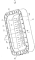
- Figure 4 shows a perspective view of a further example of an airbag arrangement
- Figure 5 shows a sectional view through the airbag arrangement of Figure 4 along line A-A.
- the view of Figure 4 is a view into the chute of the airbag arrangement, quasi from the perspective of the airbag.
- the opposite walls 182, 184 can be seen, which, together with the opposite walls 186, 188, enclose the chute.
- the airbag flap 12 closes the chute and, in the example of Figures 4 and 5 , is illustrated to include ribs 128 and recesses for stabilizing the airbag flap 12.
- the material web 30 extends on the inner side of the chute wall 182 and along the inner side of the flap 12, wherein the reinforcing ribs 128 of the flap 12 are at least partially formed above the material web 30, so that the material web 30 is located between the main body of the flap 12 and the ribs 128, as can be best seen in Figure 5 .
- the hinge area 16 and the predetermined breaking line 20 can also be seen in Figure 5 .
- the material web 30 extends with its first section 302 across the inner side of the flap 12, across the hinge area 16, and with its second section 304 along the inner side of the wall 182.
- the edgefolding 308 inside the wall 182 as well as the third section 306 of the material web 30 can be seen as well.
- Mold halves of an injection mold for manufacturing the airbag arrangement are schematically shown in Figure 5 by means of the hatchings S1 and S2.
- the nozzle side or molding side of an injection molding tool can be located on the side of the flap 12 and the wall 182 facing away from the material web (in the hatching S1), so that the material web 30 is pushed against the opposite surface of the injection mold by means of the injected material, and is thus embedded in the corresponding surfaces of the flap 12 and of the wall 182.
- the injected material inside the mold cavity, in which the wall 182 is formed thereby penetrates between the sections 304 and 306 of the material web, on both sides of the edgefolding 308, so that the material web 30 comes to rest on the two opposite surfaces of the wall 182 and is anchored in the wall 182 by means of the injected material.
- the ejector side of the injection mold is located on the opposite side of the mold, which is suggested by the hatching S2.
- the edgefolding 308 can be prefixed.
- a mold comprising a first mold shell and a second mold shell can thus be used to manufacture the airbag arrangement, the mold shells configured to integrally mold a flap, which closes a passage opening for an airbag, a hinge section along a side of the flap and a chute, which is connected to the flap via the hinge section.
- the material web is placed into the mold in such a way that a first part of the material web comes to rest on a first surface section of the mold, which is configured to form a surface of the flap facing the airbag, a second part of the material web comes to rest on a second surface section of the mold, which is configured to form an adjoining surface of the chute component, and a third part of the material web comes to rest on a third surface section of the mold, which is configured to form an opposite surface of the chute wall.
- plastic material is introduced into the closed mold, e.g. injected, wherein the first, the second, and the third part of the material web are pushed against the first, the second and the third surface section.
- the material web comprise a textile or a fabric, a knitted fabric, a film, a metal layer or a combination thereof, wherein the material web can further include natural and/or synthetic fibers.
- the material web can be expandable at least in a first direction, which extends perpendicular or approximately perpendicular to the hinge section.
Landscapes
- Engineering & Computer Science (AREA)
- Mechanical Engineering (AREA)
- Manufacturing & Machinery (AREA)
- Air Bags (AREA)
Description
- The invention relates to an airbag arrangement according to the preamble of
claim 1 and to a method for manufacturing the same. An airbag arrangement of this type is known fromEP 2 193 960 A1 . Another prior art airbag arrangement is described inUS 2014/0375029 A1 . - An airbag arrangement for a motor vehicle comprises an airbag cover, which closes a passage opening for the airbag, and which can be integrated into a vehicle trim part, for example into the support of a dashboard. Such an airbag arrangement is described for example in
DE 10 2007 053 995 A1 . The airbag cover is integrated into an opening in the dashboard and is fastened to the dashboard by means of an arrestor strap. The dashboard and the airbag cover are manufactured by means of injection molding, whereby one end of the arrestor strap is embedded into the support of the dashboard during a first injection molding process, and the other end of the arrestor strap is subsequently embedded into the airbag cover in a second injection molding process, so as to connect the dashboard and the airbag cover to one another. - A similar method for manufacturing an airbag arrangement is described in
EP 3 034 361 A1 , wherein the airbag cover and the support of the dashboard are made of one piece and a hinge section is formed between them by means of a material weakening. A reinforcing net spans the airbag cover, the hinge area and an adjacent area of the support and is attached or molded to said airbag cover in a generally planar manner. The reinforcing net extends through a part of a reinforcing rib in an arc, so as to prevent that the reinforcing net is released from the surface of the airbag cover or of the support in response to the triggering of the airbag. An ejection chute is attached to the support below the airbag cover. - It is an object of the invention to provide an airbag arrangement, which can be manufactured easily and the operation of which is safe. This object is solved by means of an airbag arrangement according to
claim 1 and by means of a method for the manufacture thereof according to claim 13. - The airbag arrangement according to the invention is defined in
claim 1. - The chute component is a part of the chute, which is located below the flap and which controls the passage of the airbag, and comprises a wall of the airbag chute, in particular a boundary wall, reinforcing wall, guide wall or positioning wall. The chute component extends at an angle relative to the plane, in which the flap is located, for example at an angle of 90° or approximately 90°. The flap, in turn, can be located in the plane of a support of an interior trim part, for example of a support of a dashboard, when the airbag arrangement is inserted into the interior trim part. The material web stabilizes the hinge section, controls the opening of the flap in response to the triggering of the airbag, and prevents that the flap is partially or completely released in response to triggering of the airbag.
- In the described airbag arrangement, if the material web between the flap and the chute component extends at an angle of 90° or approximately 90°, there is the risk that, due to the very strong forces acting on the flap, the material web is pulled out of the chute component in response to the opening of the flap, even if the material web is molded into the chute component. This can lead to an uncontrolled opening or even detaching of the flap. According to the invention, this problem is solved in that the material web is anchored in the chute component.
- For anchoring, the material web is partially arranged on the inner side of the wall and partially on the outer side of the wall of the chute component, whereby the inner side of the wall faces the airbag chute and the outer side of the wall faces away from it. The material web can have an edgefolding, e.g., which is embedded into the chute component in such a way that the material web abuts on the inner side of the wall and on the outer side of the wall on both sides of the edgefolding. To produce and fix the edgefolding, the two layers of the material web can be connected to one another adjoining the edgefolding on both sides of the edgefolding.
- The material web is arranged on the inner side of the wall from the hinge section across a first distance, and on the outer side of the wall across a second distance, wherein the material web penetrates the wall between the first distance and the second distance. In this example, the first distance should also be at least 1 mm, but it can also be longer, for example at least 2 mm, at least 3 mm, at least 4 mm, at least 5 mm, at least 10 mm, or at least 20 mm.
- Generally, U-shaped and H-shaped airbag flaps are known. In the U-shaped airbag flap, a hinge section is located along one side of the airbag flap, and a U-shaped weakening line or tear line defines the outline of the flap along the remaining sides of the airbag flap. Accordingly, the material web extends from the flap across the hinge section in the chute component. In the H-shaped airbag flap, two hinge sections are located along two opposite sides of the airbag flap, and an H-shaped weakening line or tear line defines the outline of a double flap along the remaining sides. The material web extends from the double flap across both hinge sections in opposite chute components and is embedded into the two opposite chute components and is anchored therein. The weakening line or tear line is thus located between the two hinge sections, so that the flap is divided into two flap halves, which can be pivoted open via the assigned hinge sections.
- The wall or the walls of the chute components do not need to enclose an angle of exactly 90° with the flap, the angle can for example also be in the range of between 30° and 150° or in the range of between 45° and 135°, or can be approximately 90°.
- The material web is preferably also molded into the flap.
- In one example, the flap, the hinge section and the chute component are formed as an injection molded part.
- The material web can comprise a net or a fabric. One example for a suitable material is described in
DE 10 20150 01 103 A1 . Other than a net or a fabric, the material web can also comprise a knitted fabric, a film, a metal layer or a combination thereof, wherein the material web can include natural and/or synthetic fibers. The material web can be capable of being expanded at least in a first direction, which extends perpendicular or approximately perpendicular to the hinge section. - The invention also provides a vehicle interior trim part comprising an airbag arrangement of the above-described type. The vehicle interior trim part can for example be a dashboard, an A column or B column lining, a door lining or part of a steering wheel lining.
- The invention further provides a method for manufacturing an airbag arrangement of the type described above. The method is defined in claim 13.
- The material web, which is placed into the mold, has an edgefolding between the second and the third part of the material web, so that the plastic material can penetrate into the edgefolding, when it expands in the mold, wherein the penetrating plastic material pushes the second and the third part of the material web apart and against the opposite surface sections of the mold. The edgefolding can be preformed and fixed prior to placing the material web into the mold.
- The invention will be explained below in view of different examples with reference to the drawings.
- Fig. 1a
- shows a schematic sectional view through an airbag arrangement according to one example;
- Fig. 1b
- shows a schematic sectional view through a material web of the airbag arrangement according to one example;
- Fig. 1c
- shows a top view onto the material web of
Figure 1b ; - Fig. 2
- shows schematic sectional views of five examples of an airbag arrangement, identified with A to E;
- Fig. 3
- shows schematic sectional views of five further examples of an airbag arrangement, identified with A to E;
- Fig. 4
- shows a perspective view of a further example of an airbag arrangement; and
- Fig. 5
- shows a sectional view through the airbag arrangement of
Figure 4 , along line A-A. -
Fig. 1a shows a schematic sectional view through anairbag arrangement 10 according to one example. The airbag arrangement comprises aflap 12, which closes a passage opening for an airbag (not shown). Theflap 12 is located in asupport 14, which can be connected for example to a dashboard or another interior trim part or interior lining part of a motor vehicle, when the airbag arrangement is inserted into the interior trim part. Theflap 12 is connected to a part of anejection chute 18 of the airbag arrangement via ahinge section 16. Thechute 18 is illustrated schematically inFigure 1 by means of twowalls walls flap 12 abuts on thewall 182, wherein thehinge section 16 is located on the boundary surface between theflap 12 and thewall 182. A weakening line orpredetermined breaking line 20, along which theflap 12 can be released from thesupport 14, is embodied on the opposite edges of theflap 12, in order to pivot open via thehinge section 16, when the airbag is triggered. Further walls and reinforcing ribs of the chute are illustrated at 22 and 24. - In this as well as in the other figures, the airbag arrangement is illustrated in an orientation, in which the
flap 12 points downwards and thechute 18 extends upwards from theflap 12. This corresponds to a view, in which the airbag arrangement is viewed from below or inside the interior trim part. Surfaces located on the inside are defined as surfaces, which face thechute 18, and surfaces located on the outside are defined as surfaces, which face away from thechute 18. - A
material web 30 extends from theflap 12 across thehinge section 16 into thewall 182 of the chute. Close to the surfaces of theflap 12 and of thewall 182, which face thechute 18, thematerial web 30 is embedded therein. For example when forming the flap and the chute, the material web can be injected into these. In the example ofFigure 1 , thematerial web 30 has an edgefolding, so that a part of thematerial web 30 abuts on the inner side of the wall and another part abuts on the outer side of thewall 182. Thematerial web 30 is thus anchored in thewall 182. -
Figures 1b and 1c show a sectional view and a top view onto thematerial web 30. For the manufacture of the airbag arrangement, thematerial web 30 can be folded ahead of time, so that it has afirst section 302, which in the completed airbag arrangement comes to rest along theflap 12, asecond section 304, which comes to rest along the inner side of thewall 182, and athird section 306, which comes to rest along the outer side of thewall 182. In the completed airbag arrangement, an angle of approximately 90° is formed between thefirst section 302 and thesecond section 304, when thewall 182 and the flap 3o enclose an angle of approximately 90°. However, the invention is not limited to a certain angle between the flap and the wall. Anedgefolding 308, which can be fixed in abend area 310, for example adhered, welded, sewn, riveted, stapled, or prefixed in a different way, is formed between thesecond section 304 and thethird section 306. The edgefolding can also be unfixed in the bend area, thus be folded over without fixation. - The
material web 30 follows the inner contour on the inner surface of theflap 12 and thewall 182, and is embedded therein in such a way that a thin material layer of theflap 12 and of thewall 182 surrounds thematerial web 30. Only thethird section 306 of the material web is located on the surface of thewall 182, which faces the outside, wherein the material of thewall 182 has penetrated theedgefolding 308 between thesecond section 304 and thethird section 306 of thematerial web 30 and thus fixes thematerial web 30 in thewall 182. Thanks to this fixation it can be prevented that thematerial web 30 is pulled out of thewall 182 in response to the triggering of the airbag and thus in response to the opening of theflap 12. -
Figures 2 and 3 schematically show different alternatives of the airbag arrangement, which are identified with A to E. Reference is made accordingly to the individual views asFigs. 2-A, 2-B etc.. The views ofFigure 2 show airbag arrangements comprising an H-shaped flap, and the views ofFigure 3 show airbag arrangements comprising a U-shaped flap. In the U-shaped airbag flap, the hinge section is located along one side of the airbag flap, and the material web thus extends from the flap across the hinge section into the chute component. With respect to the hinge section, the flap has a predetermined breaking line, so that the flap can pivot open via the hinge section. In the H-shaped airbag flap, two hinge sections are located along two opposite sides of the airbag flap, and the material web accordingly extends from the flap across both hinge sections into opposite chute components and is embedded into the two opposite chute components and is anchored therein. In the example shown, in the center or approximately in the center between the two hinge sections, the flap and the material web of this H-shaped example have a predetermined breaking line, which separates the flap into two flap halves, so that these flap halves can pivot open via the assigned hinge sections. The predetermined breaking line can also be arranged in such a way that the flap is divided at a different ratio, e.g. 30:70 or 40:60. -
Figure 2-A shows an example of an H-shaped airbag flap comprising a material web 30 (illustrated by a thicker line), which has two oppositesecond sections 304, which extend along the inner sides ofopposite walls material web 30 in each case has an edgefolding, which is fixed in abend area 310. Thematerial web 30 extends from the inner side of thewall 182, via afirst hinge section 162, the twoflap halves second hinge section 164, to the inner side of thewall 184. The edgefolding of thematerial web 30 is arranged and fixed in thewalls hinge sections walls material web 30 is embedded into the flap halves 122, 124 and thewalls chute 18. The twoflap halves predetermined breaking line 126, wherein the predetermined breaking line can be formed by means of a material weakening, which extends through thematerial web 30. Via thehinge sections support 14, which can be used for mounting the airbag arrangement to an interior trim part. - In a slightly different configuration, the chute with integrated flap part(s) and injected material web also can be attached to the support in a separate process step, e.g. by welding. The chute then is not integrated into the support, but forms an independent component, which is connected to the support or directly to an interior trim part. This variation is possible in all examples.
-
Figures 2-B to 2-E show modifications of the airbag arrangement ofFigure 2-A and are described below only insofar as they differ fromFigure 2-A . For the sake of clarity, not all components are provided with reference numerals. Unless otherwise specified below, the statements made above with reference toFigure 2-A applies for the examples ofFigures 2-B to 2-E . For example, thehinge areas predetermined breaking line 126 are only illustrated in the example ofFigure 2-A ; however, they can also be provided in the examples ofFigures 2-B to 2-E . - In the example of
Figure 2-B , thematerial web 30 extends across the entire inner side of thewalls walls bend area 310 is located on the end of thewalls third section 306 of the material web, however, is embedded into the material of thewalls - The example of
Figure 2-C is similar to the example ofFigure 2-A , but differs in that thematerial web 30 in each case does not have a prefixed bend area in the area of theedgefolding 308. In the area of theedgefolding 308, thematerial web 30 is folded from thesecond section 304 to thethird section 306 in an arch or bend, and penetrates thewalls second section 304 comes to rest on the inner side, and thethird section 306 comes to rest on the opposite outer side of thewalls - The example of
Figure 2-D is similar to the example of 2-C, wherein thematerial web 30 extends to the distal ends of thewalls edgefolding 308 is thus located at these ends. In this example, thematerial web 30 is embedded into the surface of thewalls - In the example of
Figure 2-E , the anchoring of thematerial web 30 in thewalls deflecting section 312 is formed between thesecond section 304 and thethird section 306 of thematerial web 30. Thematerial web 304 abuts on the inner sides of thewalls walls deflection section 312, wherein thethird section 306 extend on the outer sides of thewalls -shaped deflection of the material web is thus created, by means of which the material web is anchored in the
walls - The examples of
Figures 3-A to 3-E correspond substantially to the examples ofFigures 2-A to 2-E , wherein theairbag flap 12 is made from one piece and U-shaped. Theairbag flap 12 thus only has onehinge section 16 and one oppositepredetermined breaking line 20. Similarly as in the previous figures, thehinge section 16 and thepredetermined breaking line 20 is only shown inFigure 3-A ; however, they can also be provided in the examples ofFigures 3-B to 3-E . Thematerial web 30 extends along the inner side of theairbag flap 12, across thehinge section 16 and along the inner side or a part of the inner side of thewall 182. Thematerial web 30 is anchored in thewall 182, as described with reference toFigures 2-A to 2-E , to which reference is made. -
Figures 2 and 3 show sectional views through the airbag arrangement and illustrate how the material web extends across the airbag flap(s) and the one or the two side walls. In a direction perpendicular to the drawing plane, the material web can extend across the entire width of thechute 18 or only across a part of the width of the chute. -
Figure 4 shows a perspective view of a further example of an airbag arrangement; andFigure 5 shows a sectional view through the airbag arrangement ofFigure 4 along line A-A. The view ofFigure 4 is a view into the chute of the airbag arrangement, quasi from the perspective of the airbag. Theopposite walls opposite walls airbag flap 12 closes the chute and, in the example ofFigures 4 and5 , is illustrated to includeribs 128 and recesses for stabilizing theairbag flap 12. In the example ofFigure 4 , thematerial web 30 extends on the inner side of thechute wall 182 and along the inner side of theflap 12, wherein the reinforcingribs 128 of theflap 12 are at least partially formed above thematerial web 30, so that thematerial web 30 is located between the main body of theflap 12 and theribs 128, as can be best seen inFigure 5 . Thehinge area 16 and thepredetermined breaking line 20 can also be seen inFigure 5 . Thematerial web 30 extends with itsfirst section 302 across the inner side of theflap 12, across thehinge area 16, and with itssecond section 304 along the inner side of thewall 182. InFigure 5 , theedgefolding 308 inside thewall 182 as well as thethird section 306 of thematerial web 30 can be seen as well. - Mold halves of an injection mold for manufacturing the airbag arrangement are schematically shown in
Figure 5 by means of the hatchings S1 and S2. To manufacture the arrangement shown inFigure 5 , the nozzle side or molding side of an injection molding tool can be located on the side of theflap 12 and thewall 182 facing away from the material web (in the hatching S1), so that thematerial web 30 is pushed against the opposite surface of the injection mold by means of the injected material, and is thus embedded in the corresponding surfaces of theflap 12 and of thewall 182. As illustrated inFigure 5 , the injected material inside the mold cavity, in which thewall 182 is formed, thereby penetrates between thesections edgefolding 308, so that thematerial web 30 comes to rest on the two opposite surfaces of thewall 182 and is anchored in thewall 182 by means of the injected material. In this case, the ejector side of the injection mold is located on the opposite side of the mold, which is suggested by the hatching S2. In contrast to the view ofFigure 5 , theedgefolding 308 can be prefixed. - As suggested by the hatchings S1 and S2, a mold comprising a first mold shell and a second mold shell can thus be used to manufacture the airbag arrangement, the mold shells configured to integrally mold a flap, which closes a passage opening for an airbag, a hinge section along a side of the flap and a chute, which is connected to the flap via the hinge section. The material web is placed into the mold in such a way that a first part of the material web comes to rest on a first surface section of the mold, which is configured to form a surface of the flap facing the airbag, a second part of the material web comes to rest on a second surface section of the mold, which is configured to form an adjoining surface of the chute component, and a third part of the material web comes to rest on a third surface section of the mold, which is configured to form an opposite surface of the chute wall. After closing the mold, plastic material is introduced into the closed mold, e.g. injected, wherein the first, the second, and the third part of the material web are pushed against the first, the second and the third surface section.
- The material web comprise a textile or a fabric, a knitted fabric, a film, a metal layer or a combination thereof, wherein the material web can further include natural and/or synthetic fibers. The material web can be expandable at least in a first direction, which extends perpendicular or approximately perpendicular to the hinge section.
Claims (15)
- An airbag arrangement comprising:a flap component (12), which closes a passage opening for an airbag;a hinge section (16) along one side of the flap component (12);a chute component, which is connected to the flap component (12) via the hinge section (16); anda material web (30), which is partially arranged in the flap component (12) and partially in the chute component, and transverses the hinge section (16);wherein the material web (30) is molded into the chute component and is anchored in the material of the chute component;wherein the chute component forms a wall (182, 184) of an airbag chute 18,characterized in that the material web (30) is arranged on the inner side of the wall (182, 184) from the hinge section across a first distance, and on the outer side of the wall across a second distance, and wherein the material web (30) penetrates the wall (182, 184) between the first distance and the second distance.
- The airbag arrangement according to claim 1, wherein the chute component forms a boundary wall, reinforcing wall, guide wall or positioning wall of the airbag chute.
- The airbag arrangement according to claim 1 or 2, wherein the wall (182, 184) has an inner side of the wall, which faces the airbag chute 18, and an outer side of the wall, which faces away therefrom, and the material web (30) is embedded into the wall (182, 184) in such a way that the material web (30) is partially arranged on the inner side of the wall and partially on the outer side of the wall.
- The airbag arrangement according to claim 3, wherein the material web (30) has an edgefolding (308, 310, 312) and extends along the inner side of the wall to the edgefolding (308, 310, 312) across a distance of at least 1 mm, at least 2 mm, at least 3 mm, at least 4 mm or at least 5 mm.
- The airbag arrangement according to one of the preceding claims, wherein the material web (30) has an edgefolding (308, 310, 312), which is embedded into the wall (182, 184) in such a way that the material web (30) abuts on the inner side of the wall and on the outer side of the wall on both sides of the edgefolding (308, 310, 312).
- The airbag arrangement according to one of the preceding claims, wherein the material web (30) has an edgefolding (308, 310, 312), and wherein, at a distal end of the wall (182, 184) or at a distance to the distal end of the wall (182, 184) of the airbag chute 18, the edgefolding (308, 310, 312) is positioned in and embedded into said wall (182, 184).
- The airbag arrangement according to one of the preceding claims, wherein the material web (30) has an edgefolding (308, 310, 312), wherein the two layers of the material web are connected to one another adjoining the edgefolding (308, 310, 312) on both sides of the edgefolding.
- The airbag arrangement according to one of the preceding claims, wherein the wall (182, 184) and the flap component (12) enclose an angle of between 30° and 150° or an angle of between 45° and 135° or an angle of exactly or approximately 90°.
- The airbag arrangement according to one of the preceding claims, wherein the chute component comprises a first wall (182, 184) and an opposite second wall (184) of the airbag chute (18), wherein the material web (30) is embedded into the first and into the second wall (182, 184), 184.
- The airbag arrangement according to one of the preceding claims, wherein the material web (30) is also integrated into the flap component (12).
- The airbag arrangement according to one of the preceding claims, wherein the flap component (12), the hinge section (16) and the chute component (18) are embodied as an injection molded part.
- The airbag arrangement according to one of the preceding claims, wherein the material web (30) comprises a net, a fabric, a knitted fabric, a film, a metal layer or a combination thereof, wherein the material web (30) can include natural and/or synthetic fibers; and/or;
wherein the material web (30) is expandable at least in a first direction, which extends perpendicular or approximately perpendicular to the hinge section. - A method for manufacturing an airbag arrangement, comprising:providing a mold comprising a first mold shell and a second mold shell, which are configured to integrally form a flap component (12), which closes a passage opening for an airbag, a hinge section along a side of the flap component (12), and a chute component, which is connected to the flap component (12) via the hinge section (16);placing a material web (30) into the mold in such a way that a first part of the material web (30) comes to rest on a first surface section of the mold, which is configured to form a surface of the flap component (12), which faces the airbag, a second part of the material web (30) comes to rest on a second surface section of the mold, which is configured to form an adjoining surface of the chute component, and a third part of the material web (30) comes to rest on a third surface section of the mold, which is configured to form an opposite surface of the chute component;closing the mold;introducing plastic material into the closed mold, wherein the first, the second, and the third part of the material web (30) are pressed against the first, the second, and the third surface section;wherein the material web (30), placed into the mold, has an edgefolding (308, 310, 312) between the second and the third part of the material web, into which the plastic material penetrates, when it expands in the mold, wherein the penetrating plastic material pushes apart the second and the third part of the material web and against the opposite surfaces of the mold.
- The method according to claim 13, wherein the edgefolding (308, 310, 312) is preformed and fixed prior to placing the material web into the mold.
- The method according to claim 13 or 14, wherein the chute component is an airbag chute wall and, at a distal end of the wall or at a distance to the distal end of the wall of the airbag chute, the edgefolding is positioned in and embedded into said wall.
Applications Claiming Priority (1)
| Application Number | Priority Date | Filing Date | Title |
|---|---|---|---|
| DE102017100330.4A DE102017100330A1 (en) | 2017-01-10 | 2017-01-10 | Airbag assembly and method for its manufacture |
Publications (3)
| Publication Number | Publication Date |
|---|---|
| EP3345794A1 EP3345794A1 (en) | 2018-07-11 |
| EP3345794B1 true EP3345794B1 (en) | 2019-06-12 |
| EP3345794B2 EP3345794B2 (en) | 2026-01-14 |
Family
ID=60781949
Family Applications (1)
| Application Number | Title | Priority Date | Filing Date |
|---|---|---|---|
| EP17209724.8A Active EP3345794B2 (en) | 2017-01-10 | 2017-12-21 | Airbag arrangement and method for manufacturing the same |
Country Status (3)
| Country | Link |
|---|---|
| US (1) | US11117541B2 (en) |
| EP (1) | EP3345794B2 (en) |
| DE (1) | DE102017100330A1 (en) |
Families Citing this family (14)
| Publication number | Priority date | Publication date | Assignee | Title |
|---|---|---|---|---|
| CN108725371B (en) * | 2017-04-19 | 2021-07-13 | 福特环球技术公司 | Passenger airbag chute channel with radial rib pattern |
| DE102018006706A1 (en) * | 2018-08-24 | 2020-02-27 | K.L. Kaschier- Und Laminier Gmbh | Airbag cover assembly |
| DE102018006703A1 (en) * | 2018-08-24 | 2020-02-27 | K.L. Kaschier- Und Laminier Gmbh | An air bag assembly |
| DE102018006702A1 (en) * | 2018-08-24 | 2020-02-27 | K. L. Kaschier- Und Laminier Gmbh | Covering an airbag |
| KR102638696B1 (en) * | 2018-09-06 | 2024-02-21 | 현대모비스 주식회사 | Chute of passenger air bag |
| ES2927600T3 (en) | 2019-04-24 | 2022-11-08 | Faurecia Interieur Ind | Airbag system for a vehicle and method for manufacturing the airbag system |
| CN111267302A (en) * | 2020-02-10 | 2020-06-12 | 宁波方正汽车模具股份有限公司 | Ejection mechanism for automobile airbag cover |
| DE102020104716A1 (en) | 2020-02-24 | 2021-08-26 | K. L. Kaschier- Und Laminier Gmbh | Cover of an airbag firing channel |
| KR102452475B1 (en) * | 2020-08-26 | 2022-10-11 | 현대모비스 주식회사 | Driver air bag apparatus for vehicle |
| KR102928635B1 (en) * | 2020-12-29 | 2026-02-19 | 현대모비스 주식회사 | Airbag apparatus for vehicle |
| DE102022110150A1 (en) | 2022-04-27 | 2023-11-02 | Bayerische Motoren Werke Aktiengesellschaft | Tool and method for producing an airbag assembly |
| CN115285060B (en) * | 2022-08-04 | 2023-06-23 | 上海延锋金桥汽车饰件系统有限公司 | Airbag door structure |
| EP4527697A1 (en) * | 2023-09-21 | 2025-03-26 | Faurecia Intérieur Industrie | Trim element comprising a guiding device for an airbag, said guiding device comprising an overmolded structure |
| US20250242526A1 (en) * | 2024-01-26 | 2025-07-31 | Faurecia Interior Systems, Inc. | Vehicle interior panel with reinforcing layer and related method |
Citations (8)
| Publication number | Priority date | Publication date | Assignee | Title |
|---|---|---|---|---|
| US5901976A (en) | 1996-04-27 | 1999-05-11 | Trw Automotive Safety Systems Gmbh | Airbag lid |
| EP1752341A1 (en) | 2005-08-11 | 2007-02-14 | Peguform Bohemia k.s. | Airbag cover in instrument panel |
| WO2008087014A1 (en) | 2007-01-16 | 2008-07-24 | Johnson Controls Interiors Gmbh & Co. Kg | Vehicle fixture with airbag outlet cover |
| EP2193960A1 (en) | 2008-12-05 | 2010-06-09 | Peguform GmbH | Modular structured internal cladding component with a bullet channel module for an airbag |
| US20120126514A1 (en) | 2010-11-22 | 2012-05-24 | Hyundai Mobis Co., Ltd. | Passenger air-bag door |
| EP2727775A1 (en) | 2012-10-31 | 2014-05-07 | K.L. Kaschier- und Laminier GmbH | Air bag cover with at least one flap |
| US20140375029A1 (en) | 2013-06-24 | 2014-12-25 | Faurecia Interieur Industrie | Safety Device for Vehicle |
| EP3034361A1 (en) | 2014-12-16 | 2016-06-22 | Volvo Car Corporation | Airbag cover and manufacturing method for airbag cover |
Family Cites Families (9)
| Publication number | Priority date | Publication date | Assignee | Title |
|---|---|---|---|---|
| FR2838682B1 (en) * | 2002-04-18 | 2004-05-28 | Faurecia Interieur Ind | METHOD FOR MANUFACTURING A DASHBOARD PART PROVIDED WITH AN INFLATABLE CUSHION |
| US9889813B2 (en) * | 2006-12-07 | 2018-02-13 | Inoac Usa, Inc. | Apparatus for pressure bonding of a covering on an automotive interior component and a method for pressure bonding thereof |
| DE102007035073A1 (en) * | 2007-07-26 | 2009-02-12 | Lisa Dräxlmaier GmbH | Knitted fabrics with airbag flap inlays |
| DE102007053995B4 (en) | 2007-11-13 | 2016-12-22 | Volkswagen Ag | Method for producing an instrument panel of a motor vehicle |
| WO2013032371A1 (en) † | 2011-08-30 | 2013-03-07 | Volvo Technology Corporation | Vehicle security system and method for using the same |
| KR101382329B1 (en) * | 2012-09-19 | 2014-04-08 | 현대자동차 주식회사 | Air bag housing for vehicle and manufacturing method thereof |
| FR3007347B1 (en) * | 2013-06-24 | 2017-02-24 | Faurecia Interieur Ind | METHOD FOR INJECTION MOLDING AN INFLATABLE SAFETY CUSHION CASE. |
| FR3007350B1 (en) * | 2013-06-24 | 2015-06-05 | Faurecia Interieur Ind | SAFETY DEVICE FOR VEHICLE. |
| DE102015001103A1 (en) | 2015-01-30 | 2016-08-04 | K.L. Kaschier- Und Laminier Gmbh | Composite material for an airbag cover |
-
2017
- 2017-01-10 DE DE102017100330.4A patent/DE102017100330A1/en active Pending
- 2017-12-21 EP EP17209724.8A patent/EP3345794B2/en active Active
-
2018
- 2018-01-05 US US15/863,629 patent/US11117541B2/en active Active
Patent Citations (8)
| Publication number | Priority date | Publication date | Assignee | Title |
|---|---|---|---|---|
| US5901976A (en) | 1996-04-27 | 1999-05-11 | Trw Automotive Safety Systems Gmbh | Airbag lid |
| EP1752341A1 (en) | 2005-08-11 | 2007-02-14 | Peguform Bohemia k.s. | Airbag cover in instrument panel |
| WO2008087014A1 (en) | 2007-01-16 | 2008-07-24 | Johnson Controls Interiors Gmbh & Co. Kg | Vehicle fixture with airbag outlet cover |
| EP2193960A1 (en) | 2008-12-05 | 2010-06-09 | Peguform GmbH | Modular structured internal cladding component with a bullet channel module for an airbag |
| US20120126514A1 (en) | 2010-11-22 | 2012-05-24 | Hyundai Mobis Co., Ltd. | Passenger air-bag door |
| EP2727775A1 (en) | 2012-10-31 | 2014-05-07 | K.L. Kaschier- und Laminier GmbH | Air bag cover with at least one flap |
| US20140375029A1 (en) | 2013-06-24 | 2014-12-25 | Faurecia Interieur Industrie | Safety Device for Vehicle |
| EP3034361A1 (en) | 2014-12-16 | 2016-06-22 | Volvo Car Corporation | Airbag cover and manufacturing method for airbag cover |
Also Published As
| Publication number | Publication date |
|---|---|
| US11117541B2 (en) | 2021-09-14 |
| DE102017100330A1 (en) | 2018-07-12 |
| US20180194319A1 (en) | 2018-07-12 |
| EP3345794A1 (en) | 2018-07-11 |
| EP3345794B2 (en) | 2026-01-14 |
Similar Documents
| Publication | Publication Date | Title |
|---|---|---|
| EP3345794B1 (en) | Airbag arrangement and method for manufacturing the same | |
| US9045106B2 (en) | Safety device for vehicle | |
| US9669791B2 (en) | Airbag cover and manufacturing method for airbag cover | |
| US9010799B2 (en) | Molding in airbag door features in a vehicle interior panel using a movable mold member | |
| CN101959724B (en) | Internal panel component with integrated airbag cover, manufacture method and device therefor | |
| US9022419B2 (en) | Safety device for vehicle | |
| US9333936B2 (en) | Method for injection molding of an airbag case | |
| US11351944B2 (en) | Airbag system for a vehicle and method for manufacturing the airbag system | |
| EP2703232B1 (en) | Cladding component with insert section for covering an airbag and method for producing the interior cladding component | |
| KR101776465B1 (en) | Integrated crashpad and manufacturing method of the same | |
| US11485310B2 (en) | Airbag system for a vehicle and method for manufacturing the airbag system | |
| US20130249196A1 (en) | Instrument panel with an airbag flap | |
| JP3840897B2 (en) | Automotive interior parts with airbag cover | |
| KR100439920B1 (en) | Apparatus for deploying an air bag through a hard panel | |
| EP3401086B1 (en) | Passenger side airbag housing, manufacturing method therefor, and passenger side airbag for vehicle | |
| EP1754635A1 (en) | Instrument panel with integrated airbag cover and method of its manufacturing | |
| CN211918604U (en) | Vehicle interior panel | |
| JP6433816B2 (en) | Cover body of airbag device | |
| EP4527697A1 (en) | Trim element comprising a guiding device for an airbag, said guiding device comprising an overmolded structure | |
| JP2014100962A (en) | Air bag cover and its manufacturing method | |
| KR100710454B1 (en) | Invisible Airbag Door Structure and Manufacturing Method Thereof | |
| JP6482340B2 (en) | Vehicle interior parts | |
| JPH0733039B2 (en) | Method of manufacturing cover body for gas bag | |
| CZ2007523A3 (en) | Airbag cover stiffener | |
| JP2000211464A (en) | Interior parts for vehicles with integrated airbag door |
Legal Events
| Date | Code | Title | Description |
|---|---|---|---|
| PUAI | Public reference made under article 153(3) epc to a published international application that has entered the european phase |
Free format text: ORIGINAL CODE: 0009012 |
|
| STAA | Information on the status of an ep patent application or granted ep patent |
Free format text: STATUS: THE APPLICATION HAS BEEN PUBLISHED |
|
| AK | Designated contracting states |
Kind code of ref document: A1 Designated state(s): AL AT BE BG CH CY CZ DE DK EE ES FI FR GB GR HR HU IE IS IT LI LT LU LV MC MK MT NL NO PL PT RO RS SE SI SK SM TR |
|
| AX | Request for extension of the european patent |
Extension state: BA ME |
|
| STAA | Information on the status of an ep patent application or granted ep patent |
Free format text: STATUS: REQUEST FOR EXAMINATION WAS MADE |
|
| 17P | Request for examination filed |
Effective date: 20181221 |
|
| RBV | Designated contracting states (corrected) |
Designated state(s): AL AT BE BG CH CY CZ DE DK EE ES FI FR GB GR HR HU IE IS IT LI LT LU LV MC MK MT NL NO PL PT RO RS SE SI SK SM TR |
|
| GRAP | Despatch of communication of intention to grant a patent |
Free format text: ORIGINAL CODE: EPIDOSNIGR1 |
|
| STAA | Information on the status of an ep patent application or granted ep patent |
Free format text: STATUS: GRANT OF PATENT IS INTENDED |
|
| RIC1 | Information provided on ipc code assigned before grant |
Ipc: B60R 21/215 20110101AFI20190118BHEP Ipc: B29C 45/14 20060101ALI20190118BHEP Ipc: B29C 45/16 20060101ALI20190118BHEP |
|
| INTG | Intention to grant announced |
Effective date: 20190211 |
|
| GRAS | Grant fee paid |
Free format text: ORIGINAL CODE: EPIDOSNIGR3 |
|
| GRAA | (expected) grant |
Free format text: ORIGINAL CODE: 0009210 |
|
| STAA | Information on the status of an ep patent application or granted ep patent |
Free format text: STATUS: THE PATENT HAS BEEN GRANTED |
|
| AK | Designated contracting states |
Kind code of ref document: B1 Designated state(s): AL AT BE BG CH CY CZ DE DK EE ES FI FR GB GR HR HU IE IS IT LI LT LU LV MC MK MT NL NO PL PT RO RS SE SI SK SM TR |
|
| REG | Reference to a national code |
Ref country code: GB Ref legal event code: FG4D |
|
| REG | Reference to a national code |
Ref country code: CH Ref legal event code: EP |
|
| REG | Reference to a national code |
Ref country code: AT Ref legal event code: REF Ref document number: 1142144 Country of ref document: AT Kind code of ref document: T Effective date: 20190615 |
|
| REG | Reference to a national code |
Ref country code: DE Ref legal event code: R096 Ref document number: 602017004494 Country of ref document: DE |
|
| REG | Reference to a national code |
Ref country code: IE Ref legal event code: FG4D |
|
| REG | Reference to a national code |
Ref country code: NL Ref legal event code: MP Effective date: 20190612 |
|
| REG | Reference to a national code |
Ref country code: LT Ref legal event code: MG4D |
|
| PG25 | Lapsed in a contracting state [announced via postgrant information from national office to epo] |
Ref country code: SE Free format text: LAPSE BECAUSE OF FAILURE TO SUBMIT A TRANSLATION OF THE DESCRIPTION OR TO PAY THE FEE WITHIN THE PRESCRIBED TIME-LIMIT Effective date: 20190612 Ref country code: LT Free format text: LAPSE BECAUSE OF FAILURE TO SUBMIT A TRANSLATION OF THE DESCRIPTION OR TO PAY THE FEE WITHIN THE PRESCRIBED TIME-LIMIT Effective date: 20190612 Ref country code: FI Free format text: LAPSE BECAUSE OF FAILURE TO SUBMIT A TRANSLATION OF THE DESCRIPTION OR TO PAY THE FEE WITHIN THE PRESCRIBED TIME-LIMIT Effective date: 20190612 Ref country code: AL Free format text: LAPSE BECAUSE OF FAILURE TO SUBMIT A TRANSLATION OF THE DESCRIPTION OR TO PAY THE FEE WITHIN THE PRESCRIBED TIME-LIMIT Effective date: 20190612 Ref country code: NO Free format text: LAPSE BECAUSE OF FAILURE TO SUBMIT A TRANSLATION OF THE DESCRIPTION OR TO PAY THE FEE WITHIN THE PRESCRIBED TIME-LIMIT Effective date: 20190912 Ref country code: HR Free format text: LAPSE BECAUSE OF FAILURE TO SUBMIT A TRANSLATION OF THE DESCRIPTION OR TO PAY THE FEE WITHIN THE PRESCRIBED TIME-LIMIT Effective date: 20190612 |
|
| PG25 | Lapsed in a contracting state [announced via postgrant information from national office to epo] |
Ref country code: GR Free format text: LAPSE BECAUSE OF FAILURE TO SUBMIT A TRANSLATION OF THE DESCRIPTION OR TO PAY THE FEE WITHIN THE PRESCRIBED TIME-LIMIT Effective date: 20190913 Ref country code: LV Free format text: LAPSE BECAUSE OF FAILURE TO SUBMIT A TRANSLATION OF THE DESCRIPTION OR TO PAY THE FEE WITHIN THE PRESCRIBED TIME-LIMIT Effective date: 20190612 Ref country code: RS Free format text: LAPSE BECAUSE OF FAILURE TO SUBMIT A TRANSLATION OF THE DESCRIPTION OR TO PAY THE FEE WITHIN THE PRESCRIBED TIME-LIMIT Effective date: 20190612 Ref country code: BG Free format text: LAPSE BECAUSE OF FAILURE TO SUBMIT A TRANSLATION OF THE DESCRIPTION OR TO PAY THE FEE WITHIN THE PRESCRIBED TIME-LIMIT Effective date: 20190912 |
|
| REG | Reference to a national code |
Ref country code: AT Ref legal event code: MK05 Ref document number: 1142144 Country of ref document: AT Kind code of ref document: T Effective date: 20190612 |
|
| PG25 | Lapsed in a contracting state [announced via postgrant information from national office to epo] |
Ref country code: NL Free format text: LAPSE BECAUSE OF FAILURE TO SUBMIT A TRANSLATION OF THE DESCRIPTION OR TO PAY THE FEE WITHIN THE PRESCRIBED TIME-LIMIT Effective date: 20190612 Ref country code: AT Free format text: LAPSE BECAUSE OF FAILURE TO SUBMIT A TRANSLATION OF THE DESCRIPTION OR TO PAY THE FEE WITHIN THE PRESCRIBED TIME-LIMIT Effective date: 20190612 Ref country code: EE Free format text: LAPSE BECAUSE OF FAILURE TO SUBMIT A TRANSLATION OF THE DESCRIPTION OR TO PAY THE FEE WITHIN THE PRESCRIBED TIME-LIMIT Effective date: 20190612 Ref country code: PT Free format text: LAPSE BECAUSE OF FAILURE TO SUBMIT A TRANSLATION OF THE DESCRIPTION OR TO PAY THE FEE WITHIN THE PRESCRIBED TIME-LIMIT Effective date: 20191014 Ref country code: CZ Free format text: LAPSE BECAUSE OF FAILURE TO SUBMIT A TRANSLATION OF THE DESCRIPTION OR TO PAY THE FEE WITHIN THE PRESCRIBED TIME-LIMIT Effective date: 20190612 Ref country code: RO Free format text: LAPSE BECAUSE OF FAILURE TO SUBMIT A TRANSLATION OF THE DESCRIPTION OR TO PAY THE FEE WITHIN THE PRESCRIBED TIME-LIMIT Effective date: 20190612 Ref country code: SK Free format text: LAPSE BECAUSE OF FAILURE TO SUBMIT A TRANSLATION OF THE DESCRIPTION OR TO PAY THE FEE WITHIN THE PRESCRIBED TIME-LIMIT Effective date: 20190612 |
|
| PG25 | Lapsed in a contracting state [announced via postgrant information from national office to epo] |
Ref country code: ES Free format text: LAPSE BECAUSE OF FAILURE TO SUBMIT A TRANSLATION OF THE DESCRIPTION OR TO PAY THE FEE WITHIN THE PRESCRIBED TIME-LIMIT Effective date: 20190612 Ref country code: SM Free format text: LAPSE BECAUSE OF FAILURE TO SUBMIT A TRANSLATION OF THE DESCRIPTION OR TO PAY THE FEE WITHIN THE PRESCRIBED TIME-LIMIT Effective date: 20190612 Ref country code: IS Free format text: LAPSE BECAUSE OF FAILURE TO SUBMIT A TRANSLATION OF THE DESCRIPTION OR TO PAY THE FEE WITHIN THE PRESCRIBED TIME-LIMIT Effective date: 20191012 Ref country code: IT Free format text: LAPSE BECAUSE OF FAILURE TO SUBMIT A TRANSLATION OF THE DESCRIPTION OR TO PAY THE FEE WITHIN THE PRESCRIBED TIME-LIMIT Effective date: 20190612 |
|
| REG | Reference to a national code |
Ref country code: DE Ref legal event code: R026 Ref document number: 602017004494 Country of ref document: DE |
|
| PLBI | Opposition filed |
Free format text: ORIGINAL CODE: 0009260 |
|
| PG25 | Lapsed in a contracting state [announced via postgrant information from national office to epo] |
Ref country code: TR Free format text: LAPSE BECAUSE OF FAILURE TO SUBMIT A TRANSLATION OF THE DESCRIPTION OR TO PAY THE FEE WITHIN THE PRESCRIBED TIME-LIMIT Effective date: 20190612 |
|
| 26 | Opposition filed |
Opponent name: K.L. KASCHIER- UND LAMINIER GMBH Effective date: 20200312 |
|
| PLAX | Notice of opposition and request to file observation + time limit sent |
Free format text: ORIGINAL CODE: EPIDOSNOBS2 |
|
| PG25 | Lapsed in a contracting state [announced via postgrant information from national office to epo] |
Ref country code: DK Free format text: LAPSE BECAUSE OF FAILURE TO SUBMIT A TRANSLATION OF THE DESCRIPTION OR TO PAY THE FEE WITHIN THE PRESCRIBED TIME-LIMIT Effective date: 20190612 Ref country code: PL Free format text: LAPSE BECAUSE OF FAILURE TO SUBMIT A TRANSLATION OF THE DESCRIPTION OR TO PAY THE FEE WITHIN THE PRESCRIBED TIME-LIMIT Effective date: 20190612 |
|
| PLAF | Information modified related to communication of a notice of opposition and request to file observations + time limit |
Free format text: ORIGINAL CODE: EPIDOSCOBS2 |
|
| PG25 | Lapsed in a contracting state [announced via postgrant information from national office to epo] |
Ref country code: IS Free format text: LAPSE BECAUSE OF FAILURE TO SUBMIT A TRANSLATION OF THE DESCRIPTION OR TO PAY THE FEE WITHIN THE PRESCRIBED TIME-LIMIT Effective date: 20200224 |
|
| PG2D | Information on lapse in contracting state deleted |
Ref country code: IS |
|
| REG | Reference to a national code |
Ref country code: BE Ref legal event code: MM Effective date: 20191231 |
|
| PG25 | Lapsed in a contracting state [announced via postgrant information from national office to epo] |
Ref country code: MC Free format text: LAPSE BECAUSE OF FAILURE TO SUBMIT A TRANSLATION OF THE DESCRIPTION OR TO PAY THE FEE WITHIN THE PRESCRIBED TIME-LIMIT Effective date: 20190612 |
|
| PLBB | Reply of patent proprietor to notice(s) of opposition received |
Free format text: ORIGINAL CODE: EPIDOSNOBS3 |
|
| PG25 | Lapsed in a contracting state [announced via postgrant information from national office to epo] |
Ref country code: FR Free format text: LAPSE BECAUSE OF NON-PAYMENT OF DUE FEES Effective date: 20191231 Ref country code: LU Free format text: LAPSE BECAUSE OF NON-PAYMENT OF DUE FEES Effective date: 20191221 Ref country code: IE Free format text: LAPSE BECAUSE OF NON-PAYMENT OF DUE FEES Effective date: 20191221 |
|
| PG25 | Lapsed in a contracting state [announced via postgrant information from national office to epo] |
Ref country code: BE Free format text: LAPSE BECAUSE OF NON-PAYMENT OF DUE FEES Effective date: 20191231 |
|
| PG25 | Lapsed in a contracting state [announced via postgrant information from national office to epo] |
Ref country code: CY Free format text: LAPSE BECAUSE OF FAILURE TO SUBMIT A TRANSLATION OF THE DESCRIPTION OR TO PAY THE FEE WITHIN THE PRESCRIBED TIME-LIMIT Effective date: 20190612 |
|
| PG25 | Lapsed in a contracting state [announced via postgrant information from national office to epo] |
Ref country code: HU Free format text: LAPSE BECAUSE OF FAILURE TO SUBMIT A TRANSLATION OF THE DESCRIPTION OR TO PAY THE FEE WITHIN THE PRESCRIBED TIME-LIMIT; INVALID AB INITIO Effective date: 20171221 Ref country code: MT Free format text: LAPSE BECAUSE OF FAILURE TO SUBMIT A TRANSLATION OF THE DESCRIPTION OR TO PAY THE FEE WITHIN THE PRESCRIBED TIME-LIMIT Effective date: 20190612 |
|
| REG | Reference to a national code |
Ref country code: CH Ref legal event code: PL |
|
| PG25 | Lapsed in a contracting state [announced via postgrant information from national office to epo] |
Ref country code: SI Free format text: LAPSE BECAUSE OF FAILURE TO SUBMIT A TRANSLATION OF THE DESCRIPTION OR TO PAY THE FEE WITHIN THE PRESCRIBED TIME-LIMIT Effective date: 20190612 |
|
| PG25 | Lapsed in a contracting state [announced via postgrant information from national office to epo] |
Ref country code: CH Free format text: LAPSE BECAUSE OF NON-PAYMENT OF DUE FEES Effective date: 20201231 Ref country code: LI Free format text: LAPSE BECAUSE OF NON-PAYMENT OF DUE FEES Effective date: 20201231 |
|
| APBM | Appeal reference recorded |
Free format text: ORIGINAL CODE: EPIDOSNREFNO |
|
| APBP | Date of receipt of notice of appeal recorded |
Free format text: ORIGINAL CODE: EPIDOSNNOA2O |
|
| APAH | Appeal reference modified |
Free format text: ORIGINAL CODE: EPIDOSCREFNO |
|
| APBM | Appeal reference recorded |
Free format text: ORIGINAL CODE: EPIDOSNREFNO |
|
| APBP | Date of receipt of notice of appeal recorded |
Free format text: ORIGINAL CODE: EPIDOSNNOA2O |
|
| PG25 | Lapsed in a contracting state [announced via postgrant information from national office to epo] |
Ref country code: MK Free format text: LAPSE BECAUSE OF FAILURE TO SUBMIT A TRANSLATION OF THE DESCRIPTION OR TO PAY THE FEE WITHIN THE PRESCRIBED TIME-LIMIT Effective date: 20190612 |
|
| APBQ | Date of receipt of statement of grounds of appeal recorded |
Free format text: ORIGINAL CODE: EPIDOSNNOA3O |
|
| GBPC | Gb: european patent ceased through non-payment of renewal fee |
Effective date: 20211221 |
|
| PG25 | Lapsed in a contracting state [announced via postgrant information from national office to epo] |
Ref country code: GB Free format text: LAPSE BECAUSE OF NON-PAYMENT OF DUE FEES Effective date: 20211221 |
|
| APBU | Appeal procedure closed |
Free format text: ORIGINAL CODE: EPIDOSNNOA9O |
|
| PLAY | Examination report in opposition despatched + time limit |
Free format text: ORIGINAL CODE: EPIDOSNORE2 |
|
| PLBC | Reply to examination report in opposition received |
Free format text: ORIGINAL CODE: EPIDOSNORE3 |
|
| REG | Reference to a national code |
Ref country code: DE Ref legal event code: R081 Ref document number: 602017004494 Country of ref document: DE Owner name: INTERNATIONAL AUTOMOTIVE COMPONENTS GROUP NORT, US Free format text: FORMER OWNER: INTERNATIONAL AUTOMOTIVE COMPONENTS GROUP GMBH, 40472 DUESSELDORF, DE |
|
| PLAB | Opposition data, opponent's data or that of the opponent's representative modified |
Free format text: ORIGINAL CODE: 0009299OPPO |
|
| R26 | Opposition filed (corrected) |
Opponent name: K.L. KASCHIER- UND LAMINIER GMBH Effective date: 20200312 |
|
| PLAY | Examination report in opposition despatched + time limit |
Free format text: ORIGINAL CODE: EPIDOSNORE2 |
|
| PGFP | Annual fee paid to national office [announced via postgrant information from national office to epo] |
Ref country code: DE Payment date: 20241227 Year of fee payment: 8 |
|
| PLBC | Reply to examination report in opposition received |
Free format text: ORIGINAL CODE: EPIDOSNORE3 |
|
| PUAH | Patent maintained in amended form |
Free format text: ORIGINAL CODE: 0009272 |
|
| STAA | Information on the status of an ep patent application or granted ep patent |
Free format text: STATUS: PATENT MAINTAINED AS AMENDED |
|
| REG | Reference to a national code |
Ref country code: CH Ref legal event code: M12 Free format text: ST27 STATUS EVENT CODE: U-0-0-M10-M12 (AS PROVIDED BY THE NATIONAL OFFICE) Effective date: 20251217 |
|
| 27A | Patent maintained in amended form |
Effective date: 20260114 |
|
| AK | Designated contracting states |
Kind code of ref document: B2 Designated state(s): AL AT BE BG CH CY CZ DE DK EE ES FI FR GB GR HR HU IE IS IT LI LT LU LV MC MK MT NL NO PL PT RO RS SE SI SK SM TR |
|
| REG | Reference to a national code |
Ref country code: DE Ref legal event code: R102 Ref document number: 602017004494 Country of ref document: DE |