EP3345646A1 - Befeuchter für beatmungsgerät - Google Patents
Befeuchter für beatmungsgerät Download PDFInfo
- Publication number
- EP3345646A1 EP3345646A1 EP17196870.4A EP17196870A EP3345646A1 EP 3345646 A1 EP3345646 A1 EP 3345646A1 EP 17196870 A EP17196870 A EP 17196870A EP 3345646 A1 EP3345646 A1 EP 3345646A1
- Authority
- EP
- European Patent Office
- Prior art keywords
- metal plate
- humidifier
- heating element
- tank
- housing
- Prior art date
- Legal status (The legal status is an assumption and is not a legal conclusion. Google has not performed a legal analysis and makes no representation as to the accuracy of the status listed.)
- Granted
Links
Images


Classifications
-
- A—HUMAN NECESSITIES
- A61—MEDICAL OR VETERINARY SCIENCE; HYGIENE
- A61M—DEVICES FOR INTRODUCING MEDIA INTO, OR ONTO, THE BODY; DEVICES FOR TRANSDUCING BODY MEDIA OR FOR TAKING MEDIA FROM THE BODY; DEVICES FOR PRODUCING OR ENDING SLEEP OR STUPOR
- A61M16/00—Devices for influencing the respiratory system of patients by gas treatment, e.g. ventilators; Tracheal tubes
- A61M16/10—Preparation of respiratory gases or vapours
- A61M16/1075—Preparation of respiratory gases or vapours by influencing the temperature
- A61M16/109—Preparation of respiratory gases or vapours by influencing the temperature the humidifying liquid or the beneficial agent
-
- A—HUMAN NECESSITIES
- A61—MEDICAL OR VETERINARY SCIENCE; HYGIENE
- A61M—DEVICES FOR INTRODUCING MEDIA INTO, OR ONTO, THE BODY; DEVICES FOR TRANSDUCING BODY MEDIA OR FOR TAKING MEDIA FROM THE BODY; DEVICES FOR PRODUCING OR ENDING SLEEP OR STUPOR
- A61M16/00—Devices for influencing the respiratory system of patients by gas treatment, e.g. ventilators; Tracheal tubes
- A61M16/10—Preparation of respiratory gases or vapours
- A61M16/14—Preparation of respiratory gases or vapours by mixing different fluids, one of them being in a liquid phase
- A61M16/16—Devices to humidify the respiration air
-
- H—ELECTRICITY
- H05—ELECTRIC TECHNIQUES NOT OTHERWISE PROVIDED FOR
- H05B—ELECTRIC HEATING; ELECTRIC LIGHT SOURCES NOT OTHERWISE PROVIDED FOR; CIRCUIT ARRANGEMENTS FOR ELECTRIC LIGHT SOURCES, IN GENERAL
- H05B3/00—Ohmic-resistance heating
- H05B3/20—Heating elements having extended surface area substantially in a two-dimensional [2D] plane, e.g. plate-heater
- H05B3/22—Heating elements having extended surface area substantially in a two-dimensional [2D] plane, e.g. plate-heater non-flexible
- H05B3/28—Heating elements having extended surface area substantially in a two-dimensional [2D] plane, e.g. plate-heater non-flexible heating conductor embedded in insulating material
-
- A—HUMAN NECESSITIES
- A61—MEDICAL OR VETERINARY SCIENCE; HYGIENE
- A61M—DEVICES FOR INTRODUCING MEDIA INTO, OR ONTO, THE BODY; DEVICES FOR TRANSDUCING BODY MEDIA OR FOR TAKING MEDIA FROM THE BODY; DEVICES FOR PRODUCING OR ENDING SLEEP OR STUPOR
- A61M2205/00—General characteristics of the apparatus
- A61M2205/33—Controlling, regulating or measuring
- A61M2205/3368—Temperature
-
- A—HUMAN NECESSITIES
- A61—MEDICAL OR VETERINARY SCIENCE; HYGIENE
- A61M—DEVICES FOR INTRODUCING MEDIA INTO, OR ONTO, THE BODY; DEVICES FOR TRANSDUCING BODY MEDIA OR FOR TAKING MEDIA FROM THE BODY; DEVICES FOR PRODUCING OR ENDING SLEEP OR STUPOR
- A61M2205/00—General characteristics of the apparatus
- A61M2205/33—Controlling, regulating or measuring
- A61M2205/3379—Masses, volumes, levels of fluids in reservoirs, flow rates
- A61M2205/3389—Continuous level detection
-
- A—HUMAN NECESSITIES
- A61—MEDICAL OR VETERINARY SCIENCE; HYGIENE
- A61M—DEVICES FOR INTRODUCING MEDIA INTO, OR ONTO, THE BODY; DEVICES FOR TRANSDUCING BODY MEDIA OR FOR TAKING MEDIA FROM THE BODY; DEVICES FOR PRODUCING OR ENDING SLEEP OR STUPOR
- A61M2205/00—General characteristics of the apparatus
- A61M2205/36—General characteristics of the apparatus related to heating or cooling
- A61M2205/3653—General characteristics of the apparatus related to heating or cooling by Joule effect, i.e. electric resistance
-
- H—ELECTRICITY
- H05—ELECTRIC TECHNIQUES NOT OTHERWISE PROVIDED FOR
- H05B—ELECTRIC HEATING; ELECTRIC LIGHT SOURCES NOT OTHERWISE PROVIDED FOR; CIRCUIT ARRANGEMENTS FOR ELECTRIC LIGHT SOURCES, IN GENERAL
- H05B2203/00—Aspects relating to Ohmic resistive heating covered by group H05B3/00
- H05B2203/021—Heaters specially adapted for heating liquids
Definitions
- the invention relates to a gas humidifier for a respiratory assistance device, that is to say a medical ventilator, used for the treatment of patients at home, in particular a patient suffering from a respiratory disease of the sleep apnea type, syndrome obesity hypoventilation, chronic obstructive pulmonary disease (COPD) or acute respiratory distress syndrome (ARDS), and such a fan incorporating such a gas humidifier, in particular air.
- a medical ventilator used for the treatment of patients at home, in particular a patient suffering from a respiratory disease of the sleep apnea type, syndrome obesity hypoventilation, chronic obstructive pulmonary disease (COPD) or acute respiratory distress syndrome (ARDS), and such a fan incorporating such a gas humidifier, in particular air.
- COPD chronic obstructive pulmonary disease
- ARDS acute respiratory distress syndrome
- Some respiratory assistance devices also known as ventilators, that can be used for the treatment of home patients, include a heated humidifier for humidifying the gas supplied to patients, which humidifier heater generally comprises a reservoir and a housing in which the reservoir is housed. .
- the reservoir is adapted to hold a volume of water and is adapted to allow flow of air flow between an inlet port and an outlet port.
- the bottom of the tank comprises a heating metal plate for transmitting heat to the water, ie heating the water to vaporize it and thereby charging the air stream with water vapor so as to to moisten it.
- the case is designed to receive and house the tank.
- the bottom of the housing comprises a heating structure comprising a heating element and a metal plate for transmitting the heat produced by the heating element to the metal heating plate of the tank.
- the control of the humidification of the gas is done via the heating element of the box whose heating is controlled according to, among other things, temperature data.
- a heating element comprises in particular a resistive element, typically a resistive track which dissipates heat when it is traversed by an electric current, and one or more temperature sensor (s) for measuring the temperature of the plate.
- the heating elements are generally provided with a component playing the role of thermal fuse, which cuts the current flowing in the resistive track when the temperature exceeds a given threshold.
- the value it measures is representative of the temperature of the heating element, that is to say the temperature resulting from the heating generated by the resistive track.
- the temperature probe is in contact with the metal plate because, due to the thermal conductivity properties of the plate, its temperature results both from the heat produced by the heating element and elements on the other side of the plate.
- the temperature measured by the temperature probe in contact with the plate will be greatly reduced by the large thermal capacity represented by the volume of water contained in the reservoir.
- WO2012 / 171072 discloses a humidifier for a breathing apparatus comprising a housing, a water tank to be heated, a metal plate, a heating element and a thermal sensor.
- US-2009/0107980 and US-2012/0248636 teach similar humidifiers.
- the problem that arises is therefore to improve the control of the humidifier so that it meets the requirements of performance and safety.
- the solution according to the present invention relates to a humidifier for breathing apparatus comprising a housing adapted to receive, that is to say, to house, a water tank to be heated, said housing comprising a heating structure arranged in the bottom said housing, said heating structure comprising a first metal plate and at least one heating element arranged to transmit heat generated by said at least one heating element to said first metal plate, and a first temperature sensor in direct contact with the first metal plate, characterized in that the housing further comprises a second temperature probe in contact or near-contact of the heating element and thermally insulated from the first metal plate.
- the parts accessible to the user in particular a patient, in particular the metal plates, are kept in a range.
- temperature that does not present a risk of burn injury and, secondly, that the components that are brought to high temperatures are not likely to degrade under the effect of heat.
- This temperature measurement of the heating element is delivered by the second temperature probe which is not in contact with the first metal heating plate but which measures the temperature of the heating element, while being in contact or quasi-contact with this one.
- the second temperature sensor measures the temperature in the immediate vicinity of this heating element, such as a resistive track.
- the second probe makes it possible to measure the temperature of the hottest zones of the heating structure.
- the present invention proposes to use these temperature measurements operated by the first and second temperature probes to conduct a control, for example via a dedicated algorithm, of the current flowing through the heating element, in particular a resistive track, so as to guarantee the integrity of the various components of the heating structure with respect to the temperature.
- the adhesive layer allowing contact between the heating element and the metal plate can be sensitive to high temperatures and controlling the intrinsic temperature of the heating element avoids the degradation of this layer.
- all or part of these temperature measurements can also be used to ensure a thermal fuse function and thus a cut-off of the power supply of the heating element in the event of detection of an excessive temperature, that is, that is above a predefined security threshold.
- the invention also relates to a respiratory assistance apparatus comprising a humidifier according to the invention, in particular as described in the present description and illustrated in the figures, the respiratory assistance device connected to the humidifier according to the invention.
- the invention forms a ventilation assembly that can be used to implement home-care treatment, particularly for patients suffering from a respiratory disease such as sleep apnea, obesity hypoventilation syndrome, chronic obstructive pulmonary disease (COPD) or syndrome. acute respiratory distress (ARDS).
- a respiratory disease such as sleep apnea, obesity hypoventilation syndrome, chronic obstructive pulmonary disease (COPD) or syndrome.
- COPD chronic obstructive pulmonary disease
- ARDS acute respiratory distress
- the invention also relates to a ventilation assembly comprising a humidifier according to the invention fluidly connected to the gas outlet of a respiratory assistance apparatus, such as a medical ventilator, so as to ensure humidification of the gas delivered by the ventilator, such as air.
- a respiratory assistance apparatus such as a medical ventilator
- the humidifier is fluidly connected to a patient interface, such as a mask, nasal cannula or the like, via a gas conduit, such as a flexible hose, so as to be able to convey the humidified gas from the outlet of the humidifier. humidifier to the patient's airway.
- a patient interface such as a mask, nasal cannula or the like
- a gas conduit such as a flexible hose
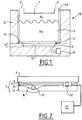
- the Figure 1 represents the principle of operation of a humidifier 18 for a breathing apparatus 19, that is to say a medical ventilator, according to the present invention, as illustrated in FIG. Figure 6 .
- the humidifier 18 comprises a housing 14 in which is housed a reservoir 1 of water 4d to be heated, as shown schematically in FIG. Figure 1 .
- the tank 1 is typically composed of a water tank 4d comprising a tray bottom 4a incorporating a metal plate 5, hereinafter called "second metal plate 5", and extending through a peripheral wall 4b integral with the bottom 4a.
- the water contained in the tank 4 is in contact with the bottom 4a, the peripheral wall 4b and the second metal plate 5 of the tank 1.
- the second metal plate 5 preferably occupies the majority of the bottom surface 4a of the tank 4.
- the tray 4 may be of plastic material and the second metal plate 5 aluminum or aluminum alloy.
- the housing 14 of the humidifier 18 comprises a heating structure 7 arranged in the bottom 15 of said housing 14, which comprises a first metal plate 6 and one (or more) heating element 10 arranged to transmit the heat produced by the heating element 10 to the first metal plate 6.
- the second metal plate 5 of the tank 1 comes into direct contact with the first metal plate 6 of the heating structure 7 of the housing 14 when the tank is housed in the housing 14 so as to transmit the heat emitted by the metal plate 6 from the heating structure 7 to the second metal plate 5 of the tank 1, then to the water 4d in contact with the second metal plate 5 of the tank 1.
- the tank 1 comprises an air inlet 2 and an outlet 3 of air so that the air can enter the internal volume 4c of the tank 4 and be charged with water vapor from the vaporization of a tank. part of the water 4d contained in the tray 4.
- the humidified air can then be discharged from the tank 4 through the outlet 3 of air, and then be directed to the airways of the patient.
- a first temperature sensor 12 is arranged to be in direct contact with the first metal plate 6 and thus be able to measure the temperature of the first metal plate 6 of the heating structure 7, and the housing 14 of the humidifier further comprises a second temperature probe 13 which comes into contact or quasi-contact with the heating element 10 while being thermally insulated from the first metal plate 6.
- the Figure 2 represents a cross-sectional view of an embodiment of the heating structure 7 of the humidifier 18 of the Figure 1 .
- this heating structure 7 comprises the first metal plate 6, for example made of aluminum or aluminum alloy, an adhesive layer 8, a first electrically insulating layer 9 providing electrical insulation, the heating element 10, such as a track resistive 10 which dissipates heat when traversed by an electric current, and a second insulating layer electrically and thermally 11.
- the adhesive layer 8 is sandwiched between the first metal plate 6 and the first electrically insulating layer 9, while the electrically insulating layer 9 is sandwiched between the adhesive layer 8 and the resistive track 10, and the resistive track 10 is sandwiched between the first electrically insulating layer 9 and the second electrically and thermally insulating layer 11.
- the first temperature sensor 12 is arranged so as to be in direct contact with the first metal plate 6, while the second temperature sensor 13 is arranged so as to be in contact with an area close to the resistive track 10 forming the heating element 10, while being thermally insulated from the first metal plate 6.
- Figure 3 represents a schematic view from above of the heating structure 7 of the Figure 2 .
- the second electrically and thermally insulating layer 11 provides electrical and thermal insulation, in particular to direct the heat flow, that is to say the heat, coming from the heating element 10 towards the metal plate 6.
- the first electrically insulating layer 9 and / or the second electrically and thermally insulating layer 11 are formed of silicone, polyimide, such as a polyimide film, or the like.
- the adhesive layer 8 may be formed of glue. It serves to ensure adhesion of the electrically insulating layer 9 to the metal plate 6.
- Such an architecture with positioning of the first and second temperature probes 12, 13 according to the present invention improves the control of the heating of the humidifier 18 while ensuring the aforementioned performance and safety requirements.
- this particular arrangement of the first and second temperature probes 12, 13 makes it possible to obtain two different temperature measurements, the difference of which varies according to what is on the other side of the heating plate. that of the quantity of residual water in the tank 4.
- This variability of the temperature difference between the measurements made by the two probes 12, 13 can be used to estimate, for example using an algorithm appropriate, the water level 4d remaining in the tank 4 of the tank 1 and detect when the tank 4 of the tank 1 is empty for example to interrupt the heating. This then makes it possible to limit unnecessary electrical consumption while reducing the risk of burns for the patient by a plate that is too hot and / or a gas that is too hot.
- the Figure 4 represents the evolution over time (in seconds: "s") of the temperature measurement (T P ) of the plate 6, given by the temperature probe 12 in contact with the metal plate 6, and the evolution of the temperature measurement (T EC ) of the heating element 10, given by the thermally insulated probe 13 of the metal plate 6, in the case where the tank 4 of the tank 3 is filled with a volume of water 4c, then that the Figure 5 represents the same changes in temperature in the case where the tank 4 of the tank 3 is empty. Temperatures are in ° C.
- control of the heating element 10 by control means which collect and process the measurement signals of the probes 12, 13 makes it possible to maintain a constant temperature at the level of the first metal plate 6 by means of a servocontrol based on the temperature measurement delivered by the first probe 12.
- a servocontrol based on the temperature measurement delivered by the first probe 12.
- this property is used to detect the absence of water 4d in the tank 1, by comparing the difference between the temperatures measured by the first and second probes 12, 13 to a reference threshold, for example a pre-recorded threshold accessible to the control software of the heating element 10.
- a reference threshold for example a pre-recorded threshold accessible to the control software of the heating element 10.
- the heating element 10 ceases to be supplied with electric current, which makes it possible, on the one hand, to reduce the power consumption when it is not possible. not useful and, secondly, to limit the heating of the first and first metal plates 6, 5 when the heat can not be dissipated in the water 4d, so as to avoid or minimize the risk of burn when the patient handles humidifier.
- the humidifier 18 of the invention can be housed in or in fluid communication with a respiratory assistance apparatus 19 adapted to receive such a humidifier 18, as illustrated in the embodiment of the invention.
- Figure 6 This represents an embodiment in which a humidifier 18 according to the invention is fluidly connected to the gas outlet of a medical fan 19 so as to humidify the gas, such as air, delivered by said fan 19 and thus obtaining humidified air which can then be administered to the airways of an individual, typically a patient suffering from a disease or respiratory insufficiency, by means of a suitable patient interface, such as a respiratory mask, cannulas nasal or the like, fed with humidified gas via a gas conduit, such as a hose.
- a gas conduit such as a hose.
- the ventilation assembly thus formed which comprises the humidifier 18 according to the invention and a medical ventilator 19, that is to say a respiratory assistance device, is well suited to treating patients at home. , including patients with sleep apnea-like respiratory disease, obesity hypoventilation syndrome, chronic obstructive pulmonary disease (COPD) or acute respiratory distress syndrome (ARDS).
- a medical ventilator 19 that is to say a respiratory assistance device
Landscapes
- Health & Medical Sciences (AREA)
- Emergency Medicine (AREA)
- Pulmonology (AREA)
- Engineering & Computer Science (AREA)
- Anesthesiology (AREA)
- Biomedical Technology (AREA)
- Heart & Thoracic Surgery (AREA)
- Hematology (AREA)
- Life Sciences & Earth Sciences (AREA)
- Animal Behavior & Ethology (AREA)
- General Health & Medical Sciences (AREA)
- Public Health (AREA)
- Veterinary Medicine (AREA)
- Air Humidification (AREA)
- Respiratory Apparatuses And Protective Means (AREA)
Applications Claiming Priority (1)
| Application Number | Priority Date | Filing Date | Title |
|---|---|---|---|
| FR1750098A FR3061437B1 (fr) | 2017-01-05 | 2017-01-05 | Humidificateur pour appareil d'assistance respiratoire |
Publications (2)
| Publication Number | Publication Date |
|---|---|
| EP3345646A1 true EP3345646A1 (de) | 2018-07-11 |
| EP3345646B1 EP3345646B1 (de) | 2019-05-29 |
Family
ID=58779130
Family Applications (1)
| Application Number | Title | Priority Date | Filing Date |
|---|---|---|---|
| EP17196870.4A Active EP3345646B1 (de) | 2017-01-05 | 2017-10-17 | Befeuchter für beatmungsgerät |
Country Status (3)
| Country | Link |
|---|---|
| EP (1) | EP3345646B1 (de) |
| ES (1) | ES2732667T3 (de) |
| FR (1) | FR3061437B1 (de) |
Cited By (2)
| Publication number | Priority date | Publication date | Assignee | Title |
|---|---|---|---|---|
| WO2020243955A1 (en) * | 2019-06-06 | 2020-12-10 | Vincent Medical (Dong Guan) Manufacturing Co., Ltd. | An improved heater plate |
| US11980714B2 (en) | 2018-08-10 | 2024-05-14 | Fisher & Paykel Healthcare Limited | Heater plate assembly in humidifier systems for medical use |
Citations (6)
| Publication number | Priority date | Publication date | Assignee | Title |
|---|---|---|---|---|
| WO2008148154A1 (en) * | 2007-06-05 | 2008-12-11 | Resmed Ltd | Electrical heater with particular application to humidification and fluid warming |
| US20090107980A1 (en) | 2007-10-29 | 2009-04-30 | Smiths Medical Asd, Inc. | Hot plate heater for a respiratory system |
| WO2010140903A1 (en) * | 2009-06-05 | 2010-12-09 | Fisher & Paykel Healthcare Limited | Humidifier heater base |
| US20120248636A1 (en) | 2011-03-29 | 2012-10-04 | Smiths Medical Asd, Inc. | Heater unit humidification chamber monitor |
| WO2012171072A1 (en) | 2011-06-16 | 2012-12-20 | Resmed Limited | Humifier and layered heating element |
| EP2848277A1 (de) * | 2013-09-12 | 2015-03-18 | Air Liquide Medical Systems | Flüssigkeitstank für medizinische Gasbefeuchtungsvorrichtung |
-
2017
- 2017-01-05 FR FR1750098A patent/FR3061437B1/fr not_active Expired - Fee Related
- 2017-10-17 ES ES17196870T patent/ES2732667T3/es active Active
- 2017-10-17 EP EP17196870.4A patent/EP3345646B1/de active Active
Patent Citations (6)
| Publication number | Priority date | Publication date | Assignee | Title |
|---|---|---|---|---|
| WO2008148154A1 (en) * | 2007-06-05 | 2008-12-11 | Resmed Ltd | Electrical heater with particular application to humidification and fluid warming |
| US20090107980A1 (en) | 2007-10-29 | 2009-04-30 | Smiths Medical Asd, Inc. | Hot plate heater for a respiratory system |
| WO2010140903A1 (en) * | 2009-06-05 | 2010-12-09 | Fisher & Paykel Healthcare Limited | Humidifier heater base |
| US20120248636A1 (en) | 2011-03-29 | 2012-10-04 | Smiths Medical Asd, Inc. | Heater unit humidification chamber monitor |
| WO2012171072A1 (en) | 2011-06-16 | 2012-12-20 | Resmed Limited | Humifier and layered heating element |
| EP2848277A1 (de) * | 2013-09-12 | 2015-03-18 | Air Liquide Medical Systems | Flüssigkeitstank für medizinische Gasbefeuchtungsvorrichtung |
Cited By (7)
| Publication number | Priority date | Publication date | Assignee | Title |
|---|---|---|---|---|
| US11980714B2 (en) | 2018-08-10 | 2024-05-14 | Fisher & Paykel Healthcare Limited | Heater plate assembly in humidifier systems for medical use |
| US20240358949A1 (en) * | 2018-08-10 | 2024-10-31 | Fisher & Paykel Healthcare Limited | Heater plate assembly in humidifier systems for medical use |
| WO2020243955A1 (en) * | 2019-06-06 | 2020-12-10 | Vincent Medical (Dong Guan) Manufacturing Co., Ltd. | An improved heater plate |
| CN113728206A (zh) * | 2019-06-06 | 2021-11-30 | 东莞永胜医疗制品有限公司 | 一种改进的加热器板 |
| JP2022534855A (ja) * | 2019-06-06 | 2022-08-04 | ヴィンセント メディカル(ドングアン)マニュファクチャリング シーオー.,エルティーディー. | 改良されたヒータープレート |
| EP3980697A4 (de) * | 2019-06-06 | 2023-01-18 | Vincent Medical (Dong Guan) Manufacturing Co., Ltd. | Verbesserte heizplatte |
| US12280217B2 (en) | 2019-06-06 | 2025-04-22 | Vincent Medical (Dong Guan) Manufacturing Co., Ltd. | Heater plate |
Also Published As
| Publication number | Publication date |
|---|---|
| FR3061437A1 (fr) | 2018-07-06 |
| FR3061437B1 (fr) | 2019-01-25 |
| ES2732667T3 (es) | 2019-11-25 |
| EP3345646B1 (de) | 2019-05-29 |
Similar Documents
| Publication | Publication Date | Title |
|---|---|---|
| US11779719B2 (en) | Wire heated tube with temperature control system for humidifier for respiratory apparatus | |
| KR102124636B1 (ko) | 에어로졸 생성 장치용 히터 | |
| RU2738556C2 (ru) | Устройство для генерирования аэрозоля с нагревателем | |
| US11732910B2 (en) | Humidifier arrangements and control systems | |
| FR2875138A1 (fr) | Procede de regulation pour un humidificateur chauffant | |
| JP6050509B2 (ja) | 電子蒸気供給装置 | |
| EP3345646B1 (de) | Befeuchter für beatmungsgerät | |
| KR20240101852A (ko) | 에어로졸 발생 디바이스의 온도 센서의 동작의 검증 | |
| US12280217B2 (en) | Heater plate | |
| EP4117471B1 (de) | Aerosolerzeugungsvorrichtung, verfahren und steuerschaltung dafür | |
| FR2570280A1 (fr) | Appareil inhalateur destine a la guerison des rhumes | |
| RU2851082C2 (ru) | Устройство, генерирующее аэрозоль, и способ управления нагревательным элементом устройства, генерирующего аэрозоль | |
| FR3064921A1 (fr) | Detection de reservoir vide dans un humidificateur chauffant | |
| NZ620523B (en) | Wire heated tube with temperature control system for humidifier for respiratory apparatus | |
| FR2985190A1 (fr) | Dispositif anti-condensation respiratoire pour installation de ventilation de patient | |
| TWM513982U (zh) | 液體加熱式電暖器 |
Legal Events
| Date | Code | Title | Description |
|---|---|---|---|
| PUAI | Public reference made under article 153(3) epc to a published international application that has entered the european phase |
Free format text: ORIGINAL CODE: 0009012 |
|
| STAA | Information on the status of an ep patent application or granted ep patent |
Free format text: STATUS: THE APPLICATION HAS BEEN PUBLISHED |
|
| AK | Designated contracting states |
Kind code of ref document: A1 Designated state(s): AL AT BE BG CH CY CZ DE DK EE ES FI FR GB GR HR HU IE IS IT LI LT LU LV MC MK MT NL NO PL PT RO RS SE SI SK SM TR |
|
| AX | Request for extension of the european patent |
Extension state: BA ME |
|
| STAA | Information on the status of an ep patent application or granted ep patent |
Free format text: STATUS: REQUEST FOR EXAMINATION WAS MADE |
|
| 17P | Request for examination filed |
Effective date: 20190111 |
|
| RBV | Designated contracting states (corrected) |
Designated state(s): AL AT BE BG CH CY CZ DE DK EE ES FI FR GB GR HR HU IE IS IT LI LT LU LV MC MK MT NL NO PL PT RO RS SE SI SK SM TR |
|
| GRAP | Despatch of communication of intention to grant a patent |
Free format text: ORIGINAL CODE: EPIDOSNIGR1 |
|
| STAA | Information on the status of an ep patent application or granted ep patent |
Free format text: STATUS: GRANT OF PATENT IS INTENDED |
|
| INTG | Intention to grant announced |
Effective date: 20190301 |
|
| GRAS | Grant fee paid |
Free format text: ORIGINAL CODE: EPIDOSNIGR3 |
|
| GRAA | (expected) grant |
Free format text: ORIGINAL CODE: 0009210 |
|
| STAA | Information on the status of an ep patent application or granted ep patent |
Free format text: STATUS: THE PATENT HAS BEEN GRANTED |
|
| AK | Designated contracting states |
Kind code of ref document: B1 Designated state(s): AL AT BE BG CH CY CZ DE DK EE ES FI FR GB GR HR HU IE IS IT LI LT LU LV MC MK MT NL NO PL PT RO RS SE SI SK SM TR |
|
| REG | Reference to a national code |
Ref country code: GB Ref legal event code: FG4D Free format text: NOT ENGLISH |
|
| REG | Reference to a national code |
Ref country code: CH Ref legal event code: EP |
|
| REG | Reference to a national code |
Ref country code: AT Ref legal event code: REF Ref document number: 1137913 Country of ref document: AT Kind code of ref document: T Effective date: 20190615 |
|
| REG | Reference to a national code |
Ref country code: DE Ref legal event code: R096 Ref document number: 602017004206 Country of ref document: DE |
|
| REG | Reference to a national code |
Ref country code: IE Ref legal event code: FG4D Free format text: LANGUAGE OF EP DOCUMENT: FRENCH |
|
| REG | Reference to a national code |
Ref country code: NL Ref legal event code: MP Effective date: 20190529 |
|
| REG | Reference to a national code |
Ref country code: LT Ref legal event code: MG4D |
|
| PG25 | Lapsed in a contracting state [announced via postgrant information from national office to epo] |
Ref country code: SE Free format text: LAPSE BECAUSE OF FAILURE TO SUBMIT A TRANSLATION OF THE DESCRIPTION OR TO PAY THE FEE WITHIN THE PRESCRIBED TIME-LIMIT Effective date: 20190529 Ref country code: HR Free format text: LAPSE BECAUSE OF FAILURE TO SUBMIT A TRANSLATION OF THE DESCRIPTION OR TO PAY THE FEE WITHIN THE PRESCRIBED TIME-LIMIT Effective date: 20190529 Ref country code: NO Free format text: LAPSE BECAUSE OF FAILURE TO SUBMIT A TRANSLATION OF THE DESCRIPTION OR TO PAY THE FEE WITHIN THE PRESCRIBED TIME-LIMIT Effective date: 20190829 Ref country code: AL Free format text: LAPSE BECAUSE OF FAILURE TO SUBMIT A TRANSLATION OF THE DESCRIPTION OR TO PAY THE FEE WITHIN THE PRESCRIBED TIME-LIMIT Effective date: 20190529 Ref country code: FI Free format text: LAPSE BECAUSE OF FAILURE TO SUBMIT A TRANSLATION OF THE DESCRIPTION OR TO PAY THE FEE WITHIN THE PRESCRIBED TIME-LIMIT Effective date: 20190529 Ref country code: PT Free format text: LAPSE BECAUSE OF FAILURE TO SUBMIT A TRANSLATION OF THE DESCRIPTION OR TO PAY THE FEE WITHIN THE PRESCRIBED TIME-LIMIT Effective date: 20190930 Ref country code: LT Free format text: LAPSE BECAUSE OF FAILURE TO SUBMIT A TRANSLATION OF THE DESCRIPTION OR TO PAY THE FEE WITHIN THE PRESCRIBED TIME-LIMIT Effective date: 20190529 |
|
| REG | Reference to a national code |
Ref country code: ES Ref legal event code: FG2A Ref document number: 2732667 Country of ref document: ES Kind code of ref document: T3 Effective date: 20191125 |
|
| PG25 | Lapsed in a contracting state [announced via postgrant information from national office to epo] |
Ref country code: BG Free format text: LAPSE BECAUSE OF FAILURE TO SUBMIT A TRANSLATION OF THE DESCRIPTION OR TO PAY THE FEE WITHIN THE PRESCRIBED TIME-LIMIT Effective date: 20190829 Ref country code: RS Free format text: LAPSE BECAUSE OF FAILURE TO SUBMIT A TRANSLATION OF THE DESCRIPTION OR TO PAY THE FEE WITHIN THE PRESCRIBED TIME-LIMIT Effective date: 20190529 Ref country code: GR Free format text: LAPSE BECAUSE OF FAILURE TO SUBMIT A TRANSLATION OF THE DESCRIPTION OR TO PAY THE FEE WITHIN THE PRESCRIBED TIME-LIMIT Effective date: 20190830 Ref country code: LV Free format text: LAPSE BECAUSE OF FAILURE TO SUBMIT A TRANSLATION OF THE DESCRIPTION OR TO PAY THE FEE WITHIN THE PRESCRIBED TIME-LIMIT Effective date: 20190529 |
|
| REG | Reference to a national code |
Ref country code: AT Ref legal event code: MK05 Ref document number: 1137913 Country of ref document: AT Kind code of ref document: T Effective date: 20190529 |
|
| PG25 | Lapsed in a contracting state [announced via postgrant information from national office to epo] |
Ref country code: DK Free format text: LAPSE BECAUSE OF FAILURE TO SUBMIT A TRANSLATION OF THE DESCRIPTION OR TO PAY THE FEE WITHIN THE PRESCRIBED TIME-LIMIT Effective date: 20190529 Ref country code: NL Free format text: LAPSE BECAUSE OF FAILURE TO SUBMIT A TRANSLATION OF THE DESCRIPTION OR TO PAY THE FEE WITHIN THE PRESCRIBED TIME-LIMIT Effective date: 20190529 Ref country code: AT Free format text: LAPSE BECAUSE OF FAILURE TO SUBMIT A TRANSLATION OF THE DESCRIPTION OR TO PAY THE FEE WITHIN THE PRESCRIBED TIME-LIMIT Effective date: 20190529 Ref country code: EE Free format text: LAPSE BECAUSE OF FAILURE TO SUBMIT A TRANSLATION OF THE DESCRIPTION OR TO PAY THE FEE WITHIN THE PRESCRIBED TIME-LIMIT Effective date: 20190529 Ref country code: RO Free format text: LAPSE BECAUSE OF FAILURE TO SUBMIT A TRANSLATION OF THE DESCRIPTION OR TO PAY THE FEE WITHIN THE PRESCRIBED TIME-LIMIT Effective date: 20190529 Ref country code: CZ Free format text: LAPSE BECAUSE OF FAILURE TO SUBMIT A TRANSLATION OF THE DESCRIPTION OR TO PAY THE FEE WITHIN THE PRESCRIBED TIME-LIMIT Effective date: 20190529 Ref country code: SK Free format text: LAPSE BECAUSE OF FAILURE TO SUBMIT A TRANSLATION OF THE DESCRIPTION OR TO PAY THE FEE WITHIN THE PRESCRIBED TIME-LIMIT Effective date: 20190529 |
|
| PG25 | Lapsed in a contracting state [announced via postgrant information from national office to epo] |
Ref country code: SM Free format text: LAPSE BECAUSE OF FAILURE TO SUBMIT A TRANSLATION OF THE DESCRIPTION OR TO PAY THE FEE WITHIN THE PRESCRIBED TIME-LIMIT Effective date: 20190529 |
|
| REG | Reference to a national code |
Ref country code: DE Ref legal event code: R097 Ref document number: 602017004206 Country of ref document: DE |
|
| PG25 | Lapsed in a contracting state [announced via postgrant information from national office to epo] |
Ref country code: TR Free format text: LAPSE BECAUSE OF FAILURE TO SUBMIT A TRANSLATION OF THE DESCRIPTION OR TO PAY THE FEE WITHIN THE PRESCRIBED TIME-LIMIT Effective date: 20190529 |
|
| PLBE | No opposition filed within time limit |
Free format text: ORIGINAL CODE: 0009261 |
|
| STAA | Information on the status of an ep patent application or granted ep patent |
Free format text: STATUS: NO OPPOSITION FILED WITHIN TIME LIMIT |
|
| PG25 | Lapsed in a contracting state [announced via postgrant information from national office to epo] |
Ref country code: PL Free format text: LAPSE BECAUSE OF FAILURE TO SUBMIT A TRANSLATION OF THE DESCRIPTION OR TO PAY THE FEE WITHIN THE PRESCRIBED TIME-LIMIT Effective date: 20190529 |
|
| 26N | No opposition filed |
Effective date: 20200303 |
|
| PG25 | Lapsed in a contracting state [announced via postgrant information from national office to epo] |
Ref country code: MC Free format text: LAPSE BECAUSE OF FAILURE TO SUBMIT A TRANSLATION OF THE DESCRIPTION OR TO PAY THE FEE WITHIN THE PRESCRIBED TIME-LIMIT Effective date: 20190529 |
|
| PG25 | Lapsed in a contracting state [announced via postgrant information from national office to epo] |
Ref country code: LU Free format text: LAPSE BECAUSE OF NON-PAYMENT OF DUE FEES Effective date: 20191017 |
|
| REG | Reference to a national code |
Ref country code: BE Ref legal event code: MM Effective date: 20191031 |
|
| PG25 | Lapsed in a contracting state [announced via postgrant information from national office to epo] |
Ref country code: BE Free format text: LAPSE BECAUSE OF NON-PAYMENT OF DUE FEES Effective date: 20191031 |
|
| PG25 | Lapsed in a contracting state [announced via postgrant information from national office to epo] |
Ref country code: IE Free format text: LAPSE BECAUSE OF NON-PAYMENT OF DUE FEES Effective date: 20191017 |
|
| PG25 | Lapsed in a contracting state [announced via postgrant information from national office to epo] |
Ref country code: CY Free format text: LAPSE BECAUSE OF FAILURE TO SUBMIT A TRANSLATION OF THE DESCRIPTION OR TO PAY THE FEE WITHIN THE PRESCRIBED TIME-LIMIT Effective date: 20190529 |
|
| REG | Reference to a national code |
Ref country code: CH Ref legal event code: PL |
|
| PG25 | Lapsed in a contracting state [announced via postgrant information from national office to epo] |
Ref country code: IS Free format text: LAPSE BECAUSE OF FAILURE TO SUBMIT A TRANSLATION OF THE DESCRIPTION OR TO PAY THE FEE WITHIN THE PRESCRIBED TIME-LIMIT Effective date: 20190929 Ref country code: LI Free format text: LAPSE BECAUSE OF FAILURE TO SUBMIT A TRANSLATION OF THE DESCRIPTION OR TO PAY THE FEE WITHIN THE PRESCRIBED TIME-LIMIT Effective date: 20201031 Ref country code: CH Free format text: LAPSE BECAUSE OF FAILURE TO SUBMIT A TRANSLATION OF THE DESCRIPTION OR TO PAY THE FEE WITHIN THE PRESCRIBED TIME-LIMIT Effective date: 20201031 |
|
| PG25 | Lapsed in a contracting state [announced via postgrant information from national office to epo] |
Ref country code: HU Free format text: LAPSE BECAUSE OF FAILURE TO SUBMIT A TRANSLATION OF THE DESCRIPTION OR TO PAY THE FEE WITHIN THE PRESCRIBED TIME-LIMIT; INVALID AB INITIO Effective date: 20171017 Ref country code: MT Free format text: LAPSE BECAUSE OF FAILURE TO SUBMIT A TRANSLATION OF THE DESCRIPTION OR TO PAY THE FEE WITHIN THE PRESCRIBED TIME-LIMIT Effective date: 20190529 |
|
| PG25 | Lapsed in a contracting state [announced via postgrant information from national office to epo] |
Ref country code: SI Free format text: LAPSE BECAUSE OF FAILURE TO SUBMIT A TRANSLATION OF THE DESCRIPTION OR TO PAY THE FEE WITHIN THE PRESCRIBED TIME-LIMIT Effective date: 20190529 |
|
| GBPC | Gb: european patent ceased through non-payment of renewal fee |
Effective date: 20211017 |
|
| PG25 | Lapsed in a contracting state [announced via postgrant information from national office to epo] |
Ref country code: MK Free format text: LAPSE BECAUSE OF FAILURE TO SUBMIT A TRANSLATION OF THE DESCRIPTION OR TO PAY THE FEE WITHIN THE PRESCRIBED TIME-LIMIT Effective date: 20190529 |
|
| PG25 | Lapsed in a contracting state [announced via postgrant information from national office to epo] |
Ref country code: GB Free format text: LAPSE BECAUSE OF NON-PAYMENT OF DUE FEES Effective date: 20211017 |
|
| PGFP | Annual fee paid to national office [announced via postgrant information from national office to epo] |
Ref country code: DE Payment date: 20251021 Year of fee payment: 9 |
|
| PGFP | Annual fee paid to national office [announced via postgrant information from national office to epo] |
Ref country code: IT Payment date: 20251021 Year of fee payment: 9 |
|
| PGFP | Annual fee paid to national office [announced via postgrant information from national office to epo] |
Ref country code: FR Payment date: 20251030 Year of fee payment: 9 |
|
| PGFP | Annual fee paid to national office [announced via postgrant information from national office to epo] |
Ref country code: ES Payment date: 20251216 Year of fee payment: 9 |