EP3345643B1 - Inhalatorabstandshalter und aufbewahrungsvorrichtung - Google Patents
Inhalatorabstandshalter und aufbewahrungsvorrichtung Download PDFInfo
- Publication number
- EP3345643B1 EP3345643B1 EP17208275.2A EP17208275A EP3345643B1 EP 3345643 B1 EP3345643 B1 EP 3345643B1 EP 17208275 A EP17208275 A EP 17208275A EP 3345643 B1 EP3345643 B1 EP 3345643B1
- Authority
- EP
- European Patent Office
- Prior art keywords
- spacer
- inhaler
- housing
- medication
- user
- Prior art date
- Legal status (The legal status is an assumption and is not a legal conclusion. Google has not performed a legal analysis and makes no representation as to the accuracy of the status listed.)
- Active
Links
Images


Classifications
-
- A—HUMAN NECESSITIES
- A61—MEDICAL OR VETERINARY SCIENCE; HYGIENE
- A61M—DEVICES FOR INTRODUCING MEDIA INTO, OR ONTO, THE BODY; DEVICES FOR TRANSDUCING BODY MEDIA OR FOR TAKING MEDIA FROM THE BODY; DEVICES FOR PRODUCING OR ENDING SLEEP OR STUPOR
- A61M15/00—Inhalators
- A61M15/0086—Inhalation chambers
-
- A—HUMAN NECESSITIES
- A61—MEDICAL OR VETERINARY SCIENCE; HYGIENE
- A61M—DEVICES FOR INTRODUCING MEDIA INTO, OR ONTO, THE BODY; DEVICES FOR TRANSDUCING BODY MEDIA OR FOR TAKING MEDIA FROM THE BODY; DEVICES FOR PRODUCING OR ENDING SLEEP OR STUPOR
- A61M15/00—Inhalators
- A61M15/009—Inhalators using medicine packages with incorporated spraying means, e.g. aerosol cans
-
- A—HUMAN NECESSITIES
- A61—MEDICAL OR VETERINARY SCIENCE; HYGIENE
- A61M—DEVICES FOR INTRODUCING MEDIA INTO, OR ONTO, THE BODY; DEVICES FOR TRANSDUCING BODY MEDIA OR FOR TAKING MEDIA FROM THE BODY; DEVICES FOR PRODUCING OR ENDING SLEEP OR STUPOR
- A61M15/00—Inhalators
- A61M15/0001—Details of inhalators; Constructional features thereof
- A61M15/0021—Mouthpieces therefor
-
- A—HUMAN NECESSITIES
- A61—MEDICAL OR VETERINARY SCIENCE; HYGIENE
- A61M—DEVICES FOR INTRODUCING MEDIA INTO, OR ONTO, THE BODY; DEVICES FOR TRANSDUCING BODY MEDIA OR FOR TAKING MEDIA FROM THE BODY; DEVICES FOR PRODUCING OR ENDING SLEEP OR STUPOR
- A61M2205/00—General characteristics of the apparatus
- A61M2205/35—Communication
- A61M2205/3576—Communication with non implanted data transmission devices, e.g. using external transmitter or receiver
- A61M2205/3584—Communication with non implanted data transmission devices, e.g. using external transmitter or receiver using modem, internet or Bluetooth®
Definitions
- This disclosure relates to an inhaler spacer that is able to store an inhaler.
- US2002/0073992 discloses an actuator for an inhaler for delivering medicament by inhalation, particularly a breath-actuated inhaler.
- Inhalers such as pressurized metered-dose inhalers (pMDIs), propellant-free soft mist inhalers (SMIs), and the like, may be used to direct medication to a person's airway in order to manage and/or treat diseases, such as asthma and COPD. When used alone, these inhalers are very inefficient and may provide an average deposition of medication to the lower airway target as low as 20% or less.
- Deposition in the lower airway target may be improved by using a spacer. While a spacer may markedly increase lung and/or lower airway drug deposition, it may suffer the shortcoming of being too large and bulky for practical daily use outside the home. Furthermore, conventional spacers fail to integrate the spacer and inhaler for improved storage and use. Therefore, there is a need for a spacer that is both extremely portable and easy to use.
- the number of patients who self-administer inhalable drugs is set to increase significantly in the coming years as many medications, such as insulin for diabetics and cancer therapy drugs, are being developed in an inhalable form. Accordingly, a device that will garner high patient compliance is critically needed.
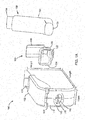
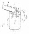
- FIGS. 1A-1E are perspective and cross-section views of an embodiment of a spacer 100 configured to store an inhaler 150.
- the spacer 100 may include a spacer housing 110 that defines a spacer chamber 115.
- the spacer chamber 115 may receive medication discharged by the inhaler 150 and may slow the delivery of the medication so more of the medication can reach the lower airway of the user when the user inhales.
- the spacer chamber 115 may slow the delivery of the medication by providing additional distance between the inhaler and the user's mouth, which may allow air friction to slow the velocity of the medication.
- the spacer housing 110 may constrain the medication from dispersing and hold the medication until it can be inhaled by the user.
- the spacer chamber 115 may be elongated along a longitudinal axis.
- the medication may be discharged substantially along the elongated longitudinal axis, and the medication may have space to slow before impacting the spacer housing 110.
- the length of the spacer housing 110 along the longitudinal axis may be selected to be short enough for the spacer 100 to fit in a pants pocket (e.g., the length may be selected to be less than or equal to the length of a selected pants pocket and/or to completely conceal the spacer in the selected pants pocket) but long enough to slow medication without substantial deposition of the medication on the spacer housing.
- a cross-section of the spacer chamber 115 normal to the longitudinal axis may be any of various shapes, such as a circle, an oval, a square with or without rounded corners, a rectangle with or without rounded corners, a hybrid between shapes, etc., and/or the size and/or shape of the cross-section may vary at different points along the longitudinal axis.
- the spacer housing 110 forms a rectangular prism with rounded edges, which has a rectangular cross-section with rounded corners.
- a height of the cross-section along a vertical axis may be larger than a width along a lateral axis. The additional height may provide space for manipulating the inhaler 150, as discussed in further detail below.
- the height of the cross-section may be selected to be short enough for the spacer 100 to fit in a pants pocket (e.g., the height of the cross-section may be selected to be less than the width of a selected pants pocket) but tall enough to permit manipulation of the inhaler 150.
- the width of the cross-section may be selected to be wide enough for an inhaler 150 to fit in the spacer chamber 115 (e.g., the width of the cross-section may be greater than or equal to the width of the inhaler 150) but otherwise may be selected to be as narrow as possible (e.g., as close to the width of the inhaler 150 as possible without restricting manipulation).
- the width may affect what height can fit in a pants pocket, so the width plus height may be selected to be less than the width of the selected pants pocket.
- the spacer housing 110 may include a concave wall 112 configured to reflect medication received from the inhaler 150 back into the spacer chamber 115. More medication may be deposited on corners, edges, flat surfaces, and the like than concave surfaces, which may direct the medication back into the spacer chamber 115 with minimal deposition.
- the concave wall 112 may be located at an edge opposite the inhaler 150, which may maximize the distance between the inhaler 150 and the concave wall 112.
- the inhaler 150 may be slightly angled relative to the longitudinal axis to aim at the concave wall 112.
- the concave wall 112 and/or the spacer housing 110 may be made of a material selected to minimize deposition of the medication, such as a non-adhesive material (e.g., polytetrafluoroethylene).
- a non-adhesive material e.g., polytetrafluoroethylene
- the spacer housing 110 may be made of a light-weight material that is resistant to deformation, such as aluminum, anti-static coated aluminum, a polymer (e.g., polycarbonate), carbon fiber, carbon-fiber-reinforced polymer, and/or the like.
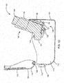
- the spacer 100 may include a retaining device 120 configured to receive the inhaler 150.
- the retaining device 120 may restrict movement of the inhaler 150 and may allow the inhaler 150 to be manipulated into predetermined positions and/or orientations.
- the retaining device 120 may include a ring 122 configured to rotatably couple with a rod 121 protruding from and/or coupled to the spacer housing 110.
- the rod 121 may define a coincident pivot point about which the retaining device 120 rotates.
- the retaining device 120 may include a rod (not shown) and the spacer housing 110 may include a cavity (not shown) that allows the rod to rotate and/or move translationally.
- the retaining device 120 may include a restraining band 124 configured to encircle an inhaler mouthpiece 151 on the inhaler 150.
- the restraining band 124 may include one or more stiff wires encircling the inhaler 150.
- the retaining device 120 may also include a backing 126 and a base 128. The restraining band 124, backing 126, and base 128 may hold the inhaler 150 sufficiently snugly to prevent excessive movement and/or inadvertent dislodgement by the inhaler but loose enough for the inhaler 150 to be inserted and removed from the retaining device 120 by the user.
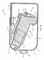
- the retaining device 120 may allow the user to move the inhaler 150 into a predetermined stored position, shown in FIG. 1E , and a predetermined active position, shown in FIGS. 1B-1D , for example, by rotating the inhaler 150 and the retaining device 120.
- the inhaler 150 may remain coupled to the retaining device 120, and the retaining device 120 may remain coupled to the spacer housing 110 during transition between the stored position and the active position. In the stored position, the inhaler 150 may be completely contained in the spacer housing 110.
- the inhaler 150 may occupy the spacer chamber 115, which may allow the spacer 100 and inhaler 150 to be more compact than they would be if they were separated and/or the inhaler 150 did not occupy the spacer chamber 115 when in the stored position.
- the inhaler mouthpiece 151 may be aimed directly at the spacer housing 110 with little or no gap between them. Thus, the inhaler 150 may not be able to effectively deliver medication to the user in the stored position.
- the inhaler 150 may be positioned to effectively deliver medication to the spacer chamber 115 and the user.
- the inhaler mouthpiece 151 may be aimed into the spacer chamber 115 and have sufficient distance between the inhaler mouthpiece 151 and the portion of the spacer housing 110 at which the mouthpiece is aimed for the medication to slow and disperse in the spacer chamber 115.
- the inhaler 150 may protrude from the spacer housing 110 in the active position, which may provide access to the inhaler 150 by the user.
- the user may be able to depress the canister 154 to release medication into the spacer chamber.
- the spacer housing 110 may be telescoping to allow the user to further increase the usable space.
- the spacer housing 110 may include a cover 130.
- the cover 130 may be rotatably coupled to the spacer housing 110 (e.g., by a hinge 132), which may allow the cover 130 to be opened without decoupling from the spacer housing 110.
- the cover 130 may rotate in any direction, such as vertically, horizontally, and/or the like.
- the cover 130 may include a sliding door 135 that can be adjusted to increase or decrease the length of the cover 130. In a closed position with the sliding door 135 extended, the cover 130 may completely conceal the inhaler 150 and the spacer chamber 115.
- the inhaler 150 may need to be in the stored position for the cover 130 to close completely with the sliding door 135 extended.
- a locking mechanism (not shown), such as a latch, hook, clip, ridge and channel, nub and dimple, magnet, friction coupling, and/or the like, may secure the cover 130 in the closed position.
- the cover 130 may automatically move to the open position when the locking mechanism is released (e.g., a spring element may rotate the cover 130 to the open position).
- the cover 130 may be opened to provide access to the inhaler 150 and allow the user to change the inhaler 150 from the stored position to the active position or vice versa.
- the cover 130 may be closed with the sliding door 135 fully retracted or partially extended when the inhaler 150 is in the active position.
- the sliding door 135 may be unable to extend completely to a closed position when the inhaler 150 is in the active position but may frictionally engage the inhaler 150 to provide additional stability. Accordingly, the user may have easy access the top of the inhaler 150 for actuating the inhaler 150.
- a plug or flexible material (not shown) may cover the top of the inhaler 150 but still allow the user to actuate the inhaler 150.
- the plug or flexible material may be made of silicone, rubber, polymer, and/or the like.
- the cover 130 may substantially seal the spacer chamber 115 when the cover 130 is closed and the inhaler 150 is in the active position. Much of the air exchange between the spacer chamber 115 and the outside may occur due to holes in the inhaler 150 between the canister 154 and the inhaler actuator/housing 152. Accordingly, the advantages of completely sealing the spacer chamber 115 may be minimal.
- the spacer chamber 115 may be substantially sealed if the area of any gaps in the spacer housing 110, not including the mouthpiece 140 and any intake valves (not shown), is no more than 0.5, 1, 2, 3, 4, 5, 10, etc. times larger than the area of the holes in the inhaler 150.
- the cover 130 may touch the inhaler 150 when the cover 130 is closed and the inhaler 150 is in the active position, but the cover 130 may not be shaped to conform to the inhaler 150. In another embodiment, the cover 130 may be shaped to conform to the inhaler 150 when the inhaler 150 is in the active position.
- the spacer housing 110 may include an air intake valve (not shown) in addition to and/or instead of gaps in the spacer housing 110.
- the air intake valve may include a one-way valve (not shown) configured to let air into the spacer chamber 115 but not out. Insufficient medication may reach the lower airway target if the user inhales too quickly, so the intake valve may alert the user if the user's inhalation rate is above a predetermined threshold.
- the intake valve may be configured to make a high-pitch whistling sound above the predetermined threshold, and/or an electronic switch may be triggered, which may light an indicator and/or produce a noise using a speaker.
- the predetermined threshold may be between 25 and 30 liters per minute in some embodiments.
- the spacer housing 110 may include a mouthpiece 140 that allows the user to inhale the medication contained in the spacer chamber 115.
- the mouthpiece 140 may be configured to switch between an active position in which the medication can be retrieved from the spacer chamber 115 and a stored position in which the mouthpiece 140 is concealed.
- the mouthpiece 140 may include a flap (not shown) that rotates between an open position that provides an opening 142 to the spacer chamber 115 through which medication can be inhaled and a closed position that covers the opening 142.
- a locking mechanism (not shown), such as a latch, hook, clip, ridge and channel, nub and dimple, magnet, friction coupling, and/or the like, may secure the flap in the closed position.
- a spring, gravity, and/or the like may automatically rotate the flap to the active position when the locking mechanism is released.
- the mouthpiece 140 may rotate to hide the opening 142, the mouthpiece 140 may be telescoping, the mouthpiece 140 may slide on a track (not shown), the opening 142 may be covered by a sliding door (not shown), the mouthpiece 140 may be made of a flexible material and may invert into the spacer chamber 115, the mouthpiece 140 may be covered by a cap (not shown), and/or the like to switch between the active and stored positions.
- the mouthpiece 140 may not protrude from the spacer housing 110 while in the stored position, and/or the cap may be flush with the spacer housing 110 in some embodiments.
- the mouthpiece 140 may include one or more exhaust ports (not shown) and/or a one-way valve (not shown) coupled to the spacer chamber 115 to prevent the user from exhaling into the spacer chamber 115, which may dispel the medication from the spacer chamber 115.
- the exhaust ports may be positioned so the user's lips do not cover the exhaust ports.
- the exhaust ports may each include a one-way exhaust valve (not shown) that prevent medication from escaping during inhalation.
- the one-way valve coupled to the spacer chamber 115 may allow air and medication from the spacer chamber 115 to travel out the mouthpiece 140 but may prevent air from entering the spacer chamber 115 through the mouthpiece 140.
- the one-way valve may include a duckbill valve, a flat valve supported by ribbing that may include any number of sections or no sections, and/or the like.
- the retaining device 120 may be configured to receive an inhaler 150 that includes a canister 154 and an inhaler actuator/housing 152.
- the retaining device 120 may secure the inhaler actuator/housing 152 in a desired position, and the inhaler actuator/housing 152 may secure the canister 154.
- the retaining device 120 may be configured to receive an inhaler including a canister 154 but without an inhaler actuator/housing 152.
- the retaining device 120 may include a nozzle block (not shown) and/or a nozzle (not shown) configured to disperse medication from the canister 154 into the spacer chamber 115.
- the restraining band 124 may be configured to encircle the canister 154, and/or the nozzle block may provide sufficient friction to hold the canister 154.
- the spacer 100 may include a dose-counting mechanism (not shown) that is visible to the user (e.g., through a window, gap, or the like) so the number of doses used and/or remaining can be seen by the user.
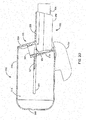
- FIGS. 2A-2E are perspective and cross-section views of another embodiment of a spacer 200 configured to store an inhaler 250.
- the spacer 200 may include a spacer housing 210 that defines a spacer chamber 215 for receiving medication discharged by the inhaler 250.
- the spacer chamber 215 may include an elongated longitudinal axis and a cross-section normal to the longitudinal axis that is oval shaped, a hybrid between a rectangle and an ellipse, and/or the like.
- the inhaler 250 may include a canister 254 and an inhaler actuator/housing 252, or the inhaler 250 may include a canister 254 only.
- the spacer 200 may include an inhaler container 220 to which the inhaler 250 may be removeably coupled.
- the inhaler container 220 may frictionally engage with the inhaler 250 to secure the inhaler 250.
- the inhaler container 220 may include a cuff 224 into which the inhaler mouthpiece 251 may be inserted.
- the user may need to apply a force greater than a predetermined threshold (e.g., gravity, a predetermined multiple of gravity, etc.) to remove the inhaler mouthpiece 251 from the cuff 224. Otherwise, the inhaler 250 may not move and/or may move minimally relative to the inhaler container 220.
- a base 228 and an upper sealing member 226 may further support and constrain movement of the inhaler 250.
- the inhaler container 220 may include one or more nubs 222 configured to move along corresponding tracks 221 in the spacer housing 210.
- the inhaler container 220 may include two nubs 222 on opposite sides of the inhaler container 220, and the spacer housing 210 may include corresponding tracks on opposite sides of the spacer housing 210 (e.g., parallel tracks in a plane normal to the vertical axis).
- the user may slide the nubs 222 along the tracks 221 to transition the inhaler container 220 and the inhaler 250 from the stored position, shown in FIG. 2C , to the active position, shown in FIGS. 2A , 2B , and 2E .
- the inhaler 250 may be completely contained in the spacer housing 210, and the inhaler mouthpiece 251 may be aimed directly at the spacer housing 210 with little or no gap between them.
- the inhaler 250 may be pointed at or substantially at the mouth piece 240 with sufficient distance between the inhaler mouthpiece 251 and the portion of the spacer housing 210 at which the inhaler mouthpiece 251 is aimed for the medication to slow and disperse in the spacer chamber 215.
- the inhaler 250 may remain secured by the inhaler container 220, and the inhaler container 220 may remain coupled to the inhaler housing 210 during transition between the stored position and the active position.
- the tracks 221 may constrain the movement of the inhaler container 220 and the inhaler 250 so the stored position and the active position are consistent between uses. For example, the tracks 221 may terminate at the appropriate locations for each position.
- the inhaler container 220 and the inhaler 250 may also need to be rotated to transition from the stored position to the active position, so the nubs 222 may be able to rotate relative to the track 221.
- the user may slide the nubs 222 to the end of the track 221 and then rotate the inhaler container 220 and the inhaler 250.
- the track 221 may end and/or include stops (not shown) to prevent excessive movement of the inhaler controller 220.
- the spacer housing 210 may include a rotation inducing mechanism (not shown), such as a hook configured to interface with a rod on the inhaler container 220 or the inhaler actuator/housing 252 or vice versa, a ball configured to interface with a socket on the inhaler container 220 or the inhaler actuator/housing 252 or vice versa, and/or the like.
- the tracks 221 may hook at the end to induce rotation.
- the inhaler container 220 may include tracks (not shown) and the spacer housing 210 may include nubs (not shown).
- the inhaler 250 may be secured in the spacer housing 210 by friction without the tracks 221 or nubs 222.
- the spacer chamber 215 may be completely sealed and/or almost completely sealed other than the mouthpiece 240, any intake valves (not shown), and holes in the inhaler 250.
- the inhaler container 220 may include an upper sealing member 226 and a lower sealing member 227 that seal the back of the spacer chamber 215.
- the upper and lower sealing members 226, 227 may be shaped like the spacer housing 210 to block the back of the spacer housing 210.
- the spacer housing 210, the upper sealing member 226, and/or the lower sealing member 227 may include a stabilizing and/or locking mechanism (not shown), such as a latch, hook, clip, ridge and channel, nub and dimple, magnet, friction coupling, and/or the like, configured to secure the inhaler container 220 and the inhaler 250 in the active position and/or the stored position.
- a stabilizing and/or locking mechanism such as a latch, hook, clip, ridge and channel, nub and dimple, magnet, friction coupling, and/or the like, configured to secure the inhaler container 220 and the inhaler 250 in the active position and/or the stored position.
- the lower sealing member 227 and/or the upper sealing member 226 may include an intake valve (not shown) and/or one or more holes (not shown) to improve air flow when the user inhales.
- the spacer housing 210 may be rotatably coupled to a cover 230, for example, by a pivot 232.
- the cover 230 may be configured to completely conceal the inhaler 250 when the cover 230 is in a closed position and the inhaler 250 is in the stored position.
- the cover 230 may be rotated by the user to an open position to provide access to the inhaler container 220 and the inhaler 250 so that the user can manipulate the inhaler container 220 and the inhaler 250 from the stored position to the active position.
- a locking mechanism (not shown), such as a latch, hook, clip, ridge and channel, nub and dimple, magnet, friction coupling, and/or the like, may be configured to secure the cover 230 in the open position and/or the closed position.
- the cover 230 may be coupled to the spacer housing 210 by a hinge (not shown); the spacer housing 210 may be configured to break apart into two parts that pivot relative to each other (e.g., at a hinge); the cover 230 may retractably slide on a track system (not shown) to open and closed positions; the inhaler container 220 may include a top portion (not shown) that seals the spacer chamber 115 when the inhaler container 220 is in the stored position; and/or the like.
- the cover 230 may not be continuous so the cover 230 can clear the spacer housing 210
- the spacer 100, 200 may include a traction element (not shown), such as finger grooves, finger grips, a grip pad on the bottom of the spacer housing 110, 120 and/or inhaler 150, 250, and/or the like, which may be made using over molded rubber, silicon, and/or the like.
- the traction element may improve the user's grasp on and/or the stability of the spacer 100, 200, for example, when the user is actuating the inhaler 150, 250.
- a carabiner hole and/or key-ring hole may allow the user to secure the spacer 100, 200 to their person and improve portability.
- a sleeve (not shown), such as a silicon wrap, may slide over the device to protect the spacer 100, 200, personalize the spacer 100, 200, provide traction, provide a hole for a carabiner and/or key ring, and/or the like.
- the spacer 100, 200 may include and/or be configured to receive a system to wirelessly transmit data on use of the spacer 100, 200.
- the system may include a GPS component configured to record the day, time, location, etc. of each actuation.
- the system may transmit the recorded information to a smartphone app., doctor's office, server, etc. manually and/or automatically using a wired and/or wireless communication device (e.g., Bluetooth).
- the system may transmit an indication of the actuation to a smartphone app., and the smartphone may record the day, time, location, etc. of the actuation.
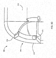
- FIGS. 3A-3D are perspective and cross-section views of a concealable mouthpiece 340 on a spacer 300.
- a user may be able to transition the mouthpiece 340 between an active position, shown in FIGS. 3A and 3C , and a stored position, shown in FIGS. 3B and 3D .
- the mouthpiece 340 may allow the user to inhale medication from a spacer chamber 315 through a mouthpiece opening 342.
- the mouthpiece 340 may completely or substantially seal the spacer chamber 315 so medication in the spacer chamber 315 cannot exit through the mouthpiece 340.
- the mouthpiece 340 may also be configured to be flush with the spacer housing 310, which may improve portability and/or storage of the spacer 300 when not in use.
- the mouthpiece 340 may include a door 344 configured to rotate about a pivot point to switch between the active and stored positions.
- the pivot point may be coincident with a pin 345 to which the door 344 is rotatably coupled.
- the user may rotate the door 344 between the active and stored positions to expose or conceal the mouthpiece opening 342.
- the mouthpiece 340 may be spring loaded and/or gravitationally loaded, and the user may push the door 344 and/or a button to release the mouthpiece 340 from the stored position.
- the mouthpiece 340 may include a tab (not shown) to allow the user to shift the mouthpiece 340 between the active and stored positions.
Landscapes
- Health & Medical Sciences (AREA)
- Engineering & Computer Science (AREA)
- Bioinformatics & Cheminformatics (AREA)
- Pulmonology (AREA)
- Anesthesiology (AREA)
- Biomedical Technology (AREA)
- Heart & Thoracic Surgery (AREA)
- Hematology (AREA)
- Life Sciences & Earth Sciences (AREA)
- Animal Behavior & Ethology (AREA)
- General Health & Medical Sciences (AREA)
- Public Health (AREA)
- Veterinary Medicine (AREA)
- Medical Preparation Storing Or Oral Administration Devices (AREA)
- Infusion, Injection, And Reservoir Apparatuses (AREA)
Claims (13)
- Abstandshaltervorrichtung (100) zum Verlangsamen der Abgabe von Medikamenten, die von einem Inhalator (150) freigesetzt werden, wobei die Abstandshaltervorrichtung (100) Folgendes umfasst:ein Abstandshaltergehäuse (110), das eine Abstandshalterkammer (115) definiert;eine Haltevorrichtung (120), die mit dem Abstandshaltergehäuse gekoppelt und dafür konfiguriert ist, den Inhalator (150) aufzunehmen;wobei die Haltevorrichtung (120) dafür konfiguriert ist, den Inhalator (150) von einer gespeicherten Position in eine aktive Position zu verschieben, in der der Inhalator (150) das Medikament an die Abstandshalterkammer (115) abgeben kann;und wobei in der geschlossenen Position der Inhalator (150) vollständig in dem Abstandshaltergehäuse (110) enthalten ist; dadurch gekennzeichnet, dass die Abstandshaltervorrichtung (100) dafür konfiguriert ist, ein Kommunikationssystem zu empfangen, um Daten über die Verwendung des Abstandshalters zu übertragen.
- Abstandshaltervorrichtung (100) nach Anspruch 1, wobei das Abstandshaltergehäuse (110) dafür konfiguriert ist, den Inhalator (150) in einer geschlossenen Position vollständig zu verbergen, wobei die Haltevorrichtung (120) dafür konfiguriert ist, den Inhalator (150) von der geschlossenen Position in eine aktive Position zu verschieben, in der der Inhalator (150) das Medikament an die Abstandshalterkammer (115) abgeben kann, und das Kommunikationssystem dafür konfiguriert ist, die aufgezeichneten Informationen manuell und/oder automatisch über eine drahtgebundene und/oder drahtlose Kommunikation zu übertragen.
- Abstandshaltervorrichtung (100) nach Anspruch 1, wobei die Daten über die Verwendung des Abstandshalters eine Betätigung des Inhalators (150) anzeigen.
- Abstandshaltervorrichtung (100) nach Anspruch 1, wobei das Kommunikationssystem dafür konfiguriert ist, die Daten über die Verwendung des Abstandshalters an ein Smartphone, eine Arztpraxis und/oder einen Server zu übertragen.
- Abstandshaltervorrichtung (100) nach einem der vorhergehenden Ansprüche, die ferner eine GPS-Komponente (Globales Positionierungssystem) umfasst, die dafür konfiguriert ist, mindestens einen Tag, eine Uhrzeit und einen Ort jeder Betätigung des Inhalators (150) aufzuzeichnen.
- Abstandshaltervorrichtung (100) nach einem der vorhergehenden Ansprüche, wobei das Kommunikationssystem ferner dafür konfiguriert ist, die Daten über die Verwendung des Abstandshalters an eine Smartphone-Anwendung zu übertragen, die dafür konfiguriert ist, mindestens einen Tag, eine Uhrzeit und einen Ort einer Betätigung des Inhalators (150) aufzuzeichnen.
- Abstandshaltervorrichtung (100) nach einem der vorhergehenden Ansprüche, wobei das Kommunikationssystem eine drahtgebundene und/oder drahtlose Kommunikationsvorrichtung umfasst.
- Abstandshaltervorrichtung (100) nach einem der vorhergehenden Ansprüche, wobei das Abstandshaltergehäuse (110) eine Abdeckung (130) umfasst, die dafür konfiguriert ist, dem Benutzer Zugang zum Inhalator (150) zu gewähren, und wobei das Abstandshaltergehäuse (110) dafür konfiguriert ist, den Inhalator (150) vollständig zu verbergen, wenn sich die Abdeckung (130) in einer geschlossenen Position befindet.
- Abstandshaltervorrichtung (100) nach einem der vorhergehenden Ansprüche, wobei die Haltevorrichtung (120) drehbar mit dem Abstandshaltergehäuse (110) gekoppelt ist und sich um einen Drehpunkt dreht, wobei sich der Drehpunkt im Abstandshaltergehäuse (110) befindet und wobei der Drehpunkt so konfiguriert ist, dass er sich relativ zum Abstandshaltergehäuse (110) bewegt.
- Abstandshaltervorrichtung (100) nach einem der vorhergehenden Ansprüche, wobei die Haltevorrichtung (120) dafür konfiguriert ist, Folgendes aufzunehmen: einen Kanister (154), der unter Druck stehende Medikamente enthält, oder einen Inhalationsaktuator (152), der dafür konfiguriert ist, freigesetzte Medikamente zu verteilen und den Kanister unterzubringen.
- Abstandshaltervorrichtung (100) nach einem der vorhergehenden Ansprüche, die ferner ein Einlassventil umfasst, das dafür konfiguriert ist, den Benutzer zu warnen, wenn die Inhalationsrate des Benutzers über einem vorbestimmten Schwellenwert liegt.
- Abstandshaltervorrichtung (100) nach Anspruch 11, wobei das Einlassventil einen elektronischen Schalter umfasst, der dafür konfiguriert ist, ausgelöst zu werden, wenn die Inhalationsrate des Benutzers über einem vorbestimmten Schwellenwert liegt.
- Abstandshaltervorrichtung (100) nach Anspruch 12, wobei der elektronische Schalter dafür konfiguriert ist, eine Anzeige zu beleuchten und/oder ein Geräusch unter Verwendung eines Lautsprechers zu erzeugen.
Applications Claiming Priority (4)
| Application Number | Priority Date | Filing Date | Title |
|---|---|---|---|
| US201361798817P | 2013-03-15 | 2013-03-15 | |
| US201361798488P | 2013-03-15 | 2013-03-15 | |
| PCT/US2013/064156 WO2014143173A1 (en) | 2013-03-15 | 2013-10-09 | Inhaler spacer and storage apparatus |
| EP13878486.3A EP2968800B1 (de) | 2013-03-15 | 2013-10-09 | Inhalator-abstandshalter und speichervorrichtung |
Related Parent Applications (1)
| Application Number | Title | Priority Date | Filing Date |
|---|---|---|---|
| EP13878486.3A Division EP2968800B1 (de) | 2013-03-15 | 2013-10-09 | Inhalator-abstandshalter und speichervorrichtung |
Publications (2)
| Publication Number | Publication Date |
|---|---|
| EP3345643A1 EP3345643A1 (de) | 2018-07-11 |
| EP3345643B1 true EP3345643B1 (de) | 2021-01-06 |
Family
ID=51537430
Family Applications (2)
| Application Number | Title | Priority Date | Filing Date |
|---|---|---|---|
| EP17208275.2A Active EP3345643B1 (de) | 2013-03-15 | 2013-10-09 | Inhalatorabstandshalter und aufbewahrungsvorrichtung |
| EP13878486.3A Active EP2968800B1 (de) | 2013-03-15 | 2013-10-09 | Inhalator-abstandshalter und speichervorrichtung |
Family Applications After (1)
| Application Number | Title | Priority Date | Filing Date |
|---|---|---|---|
| EP13878486.3A Active EP2968800B1 (de) | 2013-03-15 | 2013-10-09 | Inhalator-abstandshalter und speichervorrichtung |
Country Status (4)
| Country | Link |
|---|---|
| US (2) | US10286162B2 (de) |
| EP (2) | EP3345643B1 (de) |
| CA (1) | CA2904997C (de) |
| WO (1) | WO2014143173A1 (de) |
Families Citing this family (24)
| Publication number | Priority date | Publication date | Assignee | Title |
|---|---|---|---|---|
| US20140339213A1 (en) * | 2010-10-21 | 2014-11-20 | Fan Bao | LED Torch |
| EP3345643B1 (de) * | 2013-03-15 | 2021-01-06 | Chris V. Ciancone | Inhalatorabstandshalter und aufbewahrungsvorrichtung |
| US9994292B2 (en) * | 2015-04-22 | 2018-06-12 | Clayton Gregory Bowman | Emergency underwater miniaturized breathing device |
| CN205865984U (zh) * | 2016-08-01 | 2017-01-11 | 卓尔悦欧洲控股有限公司 | 可伸缩式烟嘴及其电子烟 |
| JP2019529012A (ja) * | 2016-09-02 | 2019-10-17 | インスピリックス,インコーポレーテッド | 呼吸増強ジェットネブライザ |
| WO2018102870A1 (en) | 2016-12-06 | 2018-06-14 | Heath Rainbow | Inhaler housing |
| CN108567168B (zh) * | 2017-03-13 | 2020-10-30 | 深圳市康尔科技有限公司 | 带有隐藏式烟嘴的电子烟及其使用方法 |
| US11504488B2 (en) | 2017-07-07 | 2022-11-22 | Paul G. Andrus | Dilution spacer and method for metered-dose inhaler |
| US10052445B1 (en) * | 2017-07-07 | 2018-08-21 | Paul G. Andrus | Dilution spacer and method for metered-dose inhaler |
| EP3649647A4 (de) | 2017-07-11 | 2021-01-27 | Cipla Limited | Einhaltungsverfolgungs- und -überwachungsvorrichtung für einen inhalator mit abgemessener dosis |
| EP4734125A2 (de) | 2018-06-04 | 2026-04-29 | Trudell Medical International Inc. | Intelligente ventilhaltekammer |
| CA3106151A1 (en) * | 2018-07-10 | 2020-01-16 | Christopher V. Ciancone | Breath measurement device |
| WO2020053878A1 (en) | 2018-09-10 | 2020-03-19 | Cipla Limited | Single blister-strip based dispenser |
| US11638802B2 (en) * | 2019-01-30 | 2023-05-02 | David Vasconcelos | Chilled-air inhaler device and methods of using a chilled-air inhaler device for the alleviation of respiratory symptoms |
| US12194229B2 (en) * | 2019-07-24 | 2025-01-14 | Trudell Medical International Inc. | Portable holding chamber |
| US11779717B2 (en) | 2019-10-12 | 2023-10-10 | Prickly Pear Innovations, LLC | Collapsible spacer for metered-dose inhalers |
| US11464923B2 (en) * | 2020-06-19 | 2022-10-11 | Norton (Waterford) Limited | Inhaler system |
| WO2022047522A1 (en) * | 2020-09-03 | 2022-03-10 | Spaceair Pty Ltd | Collapsible inhaler spacer |
| USD1010101S1 (en) | 2020-09-18 | 2024-01-02 | Trudell Medical International | Holding chamber |
| US20220347420A1 (en) * | 2021-05-03 | 2022-11-03 | Hill-Rom Services Pte. Ltd. | Funneled t-connector with nebulizer for use with a positive pressure ventilator |
| US20260069798A1 (en) * | 2022-08-10 | 2026-03-12 | Mdi Plus Limited | Metered dose inhaler storage container |
| US20250375581A1 (en) * | 2024-06-07 | 2025-12-11 | Metopi LLC | Apparatus for dispensing inhalant medicament |
| USD1089627S1 (en) * | 2025-01-30 | 2025-08-19 | Dongguan Shengzhi Technology Co., Ltd | Inhaler spacer |
| USD1092719S1 (en) * | 2025-02-05 | 2025-09-09 | Dongguan Yueming Technology Co., Ltd | Inhaler spacer with exhalation valve |
Family Cites Families (65)
| Publication number | Priority date | Publication date | Assignee | Title |
|---|---|---|---|---|
| USRE26304E (en) * | 1962-05-07 | 1967-11-21 | Aerosol dispensing package | |
| US3994421A (en) | 1975-09-29 | 1976-11-30 | American Cyanamid Company | Unitary therapeutic aerosol dispenser |
| US4509515A (en) * | 1982-02-23 | 1985-04-09 | Fisons Plc | Inhalation device |
| EP0235333B1 (de) | 1986-03-04 | 1989-05-03 | Carl Schenck Ag | Bezugsplattform für eine arretierbare Aufstellung |
| US4706663A (en) | 1986-04-25 | 1987-11-17 | Makiej Paul A | Particle catcher for inhalation devices |
| US4796614A (en) * | 1987-02-26 | 1989-01-10 | Trutek Research, Inc. | Collapsible inhalation valve |
| US4852561A (en) * | 1988-07-27 | 1989-08-01 | Sperry C R | Inhalation device |
| DE69430303T2 (de) * | 1991-03-05 | 2002-11-28 | Aradigm Corp | Verfahren und vorrichtung zur korrektur eines nullsignals eines drucksensors fur einen durchflussmesser |
| WO1993000951A1 (en) | 1991-07-02 | 1993-01-21 | Inhale, Inc. | Method and device for delivering aerosolized medicaments |
| US5284133A (en) * | 1992-07-23 | 1994-02-08 | Armstrong Pharmaceuticals, Inc. | Inhalation device with a dose-timer, an actuator mechanism, and patient compliance monitoring means |
| US5505194A (en) * | 1994-03-23 | 1996-04-09 | Abbott Laboratories | Aerosol inhalation device having slideably and rotatably connected elliptical cylinder portions |
| US5839429A (en) * | 1994-03-25 | 1998-11-24 | Astra Aktiebolag | Method and apparatus in connection with an inhaler |
| US5809997A (en) * | 1995-05-18 | 1998-09-22 | Medtrac Technologies, Inc. | Electronic medication chronolog device |
| SE9503344D0 (sv) | 1995-09-27 | 1995-09-27 | Astra Ab | Inhalation device |
| US5724986A (en) | 1995-11-06 | 1998-03-10 | Jones Medical Instrument Co. | Casing and spirometer for metered dose inhaler |
| US5904139A (en) * | 1997-03-28 | 1999-05-18 | Hauser; Stephen G. | Breath coordinated inhaler |
| IL138194A0 (en) | 1998-03-04 | 2001-10-31 | Delsys Pharmaceutical Corp | Medicament dry powder inhaler dispensing device |
| SE9801078D0 (sv) * | 1998-03-27 | 1998-03-27 | Shl Medical Ab | Inhalator |
| SE9801077D0 (sv) * | 1998-03-27 | 1998-03-27 | Shl Medical Ab | Inhalator |
| US6146685A (en) | 1998-11-05 | 2000-11-14 | Delsys Pharmaceutical Corporation | Method of deposition a dry powder and dispensing device |
| US6752148B1 (en) | 1999-02-10 | 2004-06-22 | Delsys Pharmaceutical Company | Medicament dry powder inhaler dispensing device |
| CA2377566C (en) | 1999-05-20 | 2007-08-07 | Iep Pharmaceutical Devices, Inc. | Low spray force, low retention atomization system |
| GB0002798D0 (en) | 2000-02-09 | 2000-03-29 | Glaxo Group Ltd | Actuator nozzle for metered dose inhaler |
| US6595204B2 (en) * | 2001-03-01 | 2003-07-22 | Iep Pharmaceutical Devices Inc. | Spacer for an inhaler |
| US6698422B2 (en) * | 2001-03-12 | 2004-03-02 | Birdsong Medical Devices, Inc. | Canister inhaler having a spacer and easy to operate lever mechanism and a flexible, elastic mouthpiece |
| US7225807B2 (en) | 2001-03-15 | 2007-06-05 | Creare Incorporated | Systems and methods for aerosol delivery of agents |
| AUPR387701A0 (en) | 2001-03-21 | 2001-04-12 | Infamed Limited | Improved spacer device |
| CA2444729A1 (en) | 2001-05-10 | 2002-11-14 | Vectura Delivery Devices Limited | Inhalers |
| US6595206B2 (en) | 2001-07-13 | 2003-07-22 | John Vito | Extendable spacer device and metered dose inhaler |
| DK1446172T3 (da) | 2001-09-06 | 2010-08-02 | Microdose Therapeutx Inc | Tilpasningsstykker til inhalationsapparater og som tjener til at forbedre sidstnævntes ydelse |
| US6684880B2 (en) | 2001-12-04 | 2004-02-03 | Hewlett-Packard Development Company, L.P. | Applicator for dispensing bioactive compositions and methods for using the same |
| DE50205230D1 (de) | 2002-02-14 | 2006-01-12 | Atmed Ag | Inhalationshilfsgerät |
| US6932082B2 (en) | 2002-04-19 | 2005-08-23 | 3M Innovative Properties Company | Spacer or actuator for inertial removal of the non-respirable fraction of medicinal aerosols |
| US7284553B2 (en) | 2002-12-12 | 2007-10-23 | Boehringer Ingelheim Pharma Gmbh & Co. Kg | Powder inhaler comprising a chamber for a capsule for taking up a non-returnable capsule being filled with an active ingredient |
| WO2004060260A2 (en) | 2002-12-18 | 2004-07-22 | Glaxo Group Limited | Drug delivery system with vented mouthpiece |
| US7878193B2 (en) | 2003-01-14 | 2011-02-01 | Boehringer Ingelheim International Gmbh | Capsule for taking an active substance which can be inhaled |
| US7360537B2 (en) | 2003-04-16 | 2008-04-22 | Trudell Medical International | Antistatic medication delivery apparatus |
| GB2407042B (en) | 2003-10-17 | 2007-10-24 | Vectura Ltd | Inhaler |
| US7107987B2 (en) | 2004-02-10 | 2006-09-19 | Cfd Research Corporation | Spacer for delivery of medications from an inhaler to children and breathing impaired patients |
| DE102004012093A1 (de) | 2004-03-05 | 2005-09-22 | Boehringer Ingelheim Pharma Gmbh & Co. Kg | Pulverinhalator mit Merkanaldüse |
| US20060130838A1 (en) | 2004-12-20 | 2006-06-22 | Lee Yong Y | Data logger for monitoring asthmatic conditions |
| US8226610B2 (en) * | 2005-02-01 | 2012-07-24 | Intelliject, Inc. | Medical injector with compliance tracking and monitoring |
| US7624731B2 (en) | 2005-03-16 | 2009-12-01 | Dennis R Walstrom | HME/MDI apparatus having MDI in parallel to HME |
| DE502005001542D1 (de) | 2005-07-06 | 2007-10-31 | Activaero Gmbh | Regelbares Ventil und Inhalationsvorrichtung |
| WO2007022573A1 (en) | 2005-08-22 | 2007-03-01 | Medi-Stream Pty Ltd | Medication dispenser and carrier therefor |
| WO2007041669A2 (en) | 2005-10-04 | 2007-04-12 | Sp Medical Llc | Metered dose inhaler having spacing device |
| US7861713B2 (en) | 2006-06-08 | 2011-01-04 | Sunil Kumar Dhuper | Adapter for use in an aerosol delivery system |
| US20080087279A1 (en) * | 2006-10-11 | 2008-04-17 | Tieck Catharine Laureen Johnso | Metered dose inhaler |
| GB0621957D0 (en) | 2006-11-03 | 2006-12-13 | Vectura Group Plc | Inhaler devices and bespoke pharmaceutical compositions |
| US20080178872A1 (en) * | 2006-12-01 | 2008-07-31 | Perry Genova | Dose selective breath actuated inhaler |
| WO2008097645A1 (en) * | 2007-02-08 | 2008-08-14 | Aerovectrx Corporation | Aerosol delivery systems and methods |
| MX2009009061A (es) | 2007-02-28 | 2009-11-12 | Abbott Respiratory Llc | Sistema de atomizacion a base de boquilla. |
| US20080210225A1 (en) | 2007-03-01 | 2008-09-04 | Rapha Institute For Health | Disposable antistatic spacer |
| EP2134396A2 (de) | 2007-04-06 | 2009-12-23 | Becton, Dickinson and Company, Wagner, Jaconda | Einwegabstandsstück zur inhalatorischen verabreichung zerstäubter medikamente und impfstoffe |
| US7832393B2 (en) | 2007-07-03 | 2010-11-16 | John Vito | Spacer/holding chamber for pressurized metered dose inhaler |
| WO2009018397A1 (en) | 2007-07-30 | 2009-02-05 | Green Eric M | One-piece foldable mask and holding chamber for use with aerosolized medications |
| US20090064996A1 (en) | 2007-09-10 | 2009-03-12 | Rosh Melvin S | Duo chamber |
| CN102264421B (zh) | 2008-12-23 | 2014-02-12 | 皇家飞利浦电子股份有限公司 | 用于气雾剂药物输送的方法和包括台阶式吹口的装置 |
| US9302060B2 (en) | 2009-12-04 | 2016-04-05 | Koninklijke Philips N.V. | Apparatus and method comprising adjustable stepped mouthpiece for aerosol drug delivery |
| US20110253139A1 (en) | 2010-04-15 | 2011-10-20 | Spectrum Health Innovations, LLC | Inhaler module and related system |
| US9861772B2 (en) | 2010-05-15 | 2018-01-09 | Rai Strategic Holdings, Inc. | Personal vaporizing inhaler cartridge |
| WO2012026963A2 (en) * | 2010-08-23 | 2012-03-01 | Darren Rubin | Systems and methods of aerosol delivery with airflow regulation |
| WO2012114322A1 (en) | 2011-02-24 | 2012-08-30 | Oglesby & Butler Research & Development Limited | A vaporising device |
| US10046123B2 (en) * | 2012-10-31 | 2018-08-14 | Inhaletech Llc | Systems and methods for administering pulmonary medications |
| EP3345643B1 (de) * | 2013-03-15 | 2021-01-06 | Chris V. Ciancone | Inhalatorabstandshalter und aufbewahrungsvorrichtung |
-
2013
- 2013-10-09 EP EP17208275.2A patent/EP3345643B1/de active Active
- 2013-10-09 US US14/776,041 patent/US10286162B2/en active Active
- 2013-10-09 EP EP13878486.3A patent/EP2968800B1/de active Active
- 2013-10-09 CA CA2904997A patent/CA2904997C/en active Active
- 2013-10-09 WO PCT/US2013/064156 patent/WO2014143173A1/en not_active Ceased
-
2019
- 2019-05-10 US US16/409,572 patent/US10814078B2/en active Active
Non-Patent Citations (1)
| Title |
|---|
| None * |
Also Published As
| Publication number | Publication date |
|---|---|
| EP2968800A1 (de) | 2016-01-20 |
| US20190262556A1 (en) | 2019-08-29 |
| EP2968800A4 (de) | 2016-11-16 |
| CA2904997A1 (en) | 2014-09-18 |
| EP2968800B1 (de) | 2017-12-20 |
| EP3345643A1 (de) | 2018-07-11 |
| CA2904997C (en) | 2022-12-06 |
| US10286162B2 (en) | 2019-05-14 |
| US20160022933A1 (en) | 2016-01-28 |
| WO2014143173A1 (en) | 2014-09-18 |
| US10814078B2 (en) | 2020-10-27 |
Similar Documents
| Publication | Publication Date | Title |
|---|---|---|
| US10814078B2 (en) | Inhaler spacer and storage apparatus | |
| US8109267B2 (en) | Simple inhaler | |
| US20080087279A1 (en) | Metered dose inhaler | |
| DK1051212T3 (da) | Inhalationsapparat til pulverformige medikamenter | |
| TNSN06367A1 (en) | Inhaler device | |
| NZ592675A (en) | Inhaler with a rotatable cap for sequentially moving blisters into alignment with a blister piercing member | |
| US20130037021A1 (en) | Inhaler | |
| US20190388632A1 (en) | Inhaler devices for monitoring airflow | |
| US20230233417A1 (en) | Pacifier | |
| US20240424231A1 (en) | Inhalation and exhalation devices | |
| US12569630B2 (en) | Metered dose inhaler with mouthpiece extension | |
| RU2803388C2 (ru) | Ингаляционная камера | |
| US20240075219A1 (en) | Nebulizer with flutter valve | |
| SE2251382A1 (en) | Pacifier | |
| Pearce | Teaching technique: Part 1 |
Legal Events
| Date | Code | Title | Description |
|---|---|---|---|
| PUAI | Public reference made under article 153(3) epc to a published international application that has entered the european phase |
Free format text: ORIGINAL CODE: 0009012 |
|
| STAA | Information on the status of an ep patent application or granted ep patent |
Free format text: STATUS: THE APPLICATION HAS BEEN PUBLISHED |
|
| AC | Divisional application: reference to earlier application |
Ref document number: 2968800 Country of ref document: EP Kind code of ref document: P |
|
| AK | Designated contracting states |
Kind code of ref document: A1 Designated state(s): AL AT BE BG CH CY CZ DE DK EE ES FI FR GB GR HR HU IE IS IT LI LT LU LV MC MK MT NL NO PL PT RO RS SE SI SK SM TR |
|
| STAA | Information on the status of an ep patent application or granted ep patent |
Free format text: STATUS: REQUEST FOR EXAMINATION WAS MADE |
|
| 17P | Request for examination filed |
Effective date: 20190110 |
|
| RBV | Designated contracting states (corrected) |
Designated state(s): AL AT BE BG CH CY CZ DE DK EE ES FI FR GB GR HR HU IE IS IT LI LT LU LV MC MK MT NL NO PL PT RO RS SE SI SK SM TR |
|
| GRAP | Despatch of communication of intention to grant a patent |
Free format text: ORIGINAL CODE: EPIDOSNIGR1 |
|
| STAA | Information on the status of an ep patent application or granted ep patent |
Free format text: STATUS: GRANT OF PATENT IS INTENDED |
|
| INTG | Intention to grant announced |
Effective date: 20200610 |
|
| GRAS | Grant fee paid |
Free format text: ORIGINAL CODE: EPIDOSNIGR3 |
|
| GRAJ | Information related to disapproval of communication of intention to grant by the applicant or resumption of examination proceedings by the epo deleted |
Free format text: ORIGINAL CODE: EPIDOSDIGR1 |
|
| GRAL | Information related to payment of fee for publishing/printing deleted |
Free format text: ORIGINAL CODE: EPIDOSDIGR3 |
|
| STAA | Information on the status of an ep patent application or granted ep patent |
Free format text: STATUS: REQUEST FOR EXAMINATION WAS MADE |
|
| GRAR | Information related to intention to grant a patent recorded |
Free format text: ORIGINAL CODE: EPIDOSNIGR71 |
|
| STAA | Information on the status of an ep patent application or granted ep patent |
Free format text: STATUS: GRANT OF PATENT IS INTENDED |
|
| INTC | Intention to grant announced (deleted) | ||
| GRAA | (expected) grant |
Free format text: ORIGINAL CODE: 0009210 |
|
| STAA | Information on the status of an ep patent application or granted ep patent |
Free format text: STATUS: THE PATENT HAS BEEN GRANTED |
|
| AC | Divisional application: reference to earlier application |
Ref document number: 2968800 Country of ref document: EP Kind code of ref document: P |
|
| AK | Designated contracting states |
Kind code of ref document: B1 Designated state(s): AL AT BE BG CH CY CZ DE DK EE ES FI FR GB GR HR HU IE IS IT LI LT LU LV MC MK MT NL NO PL PT RO RS SE SI SK SM TR |
|
| INTG | Intention to grant announced |
Effective date: 20201127 |
|
| REG | Reference to a national code |
Ref country code: GB Ref legal event code: FG4D |
|
| REG | Reference to a national code |
Ref country code: AT Ref legal event code: REF Ref document number: 1351670 Country of ref document: AT Kind code of ref document: T Effective date: 20210115 Ref country code: CH Ref legal event code: EP |
|
| REG | Reference to a national code |
Ref country code: DE Ref legal event code: R096 Ref document number: 602013075248 Country of ref document: DE |
|
| REG | Reference to a national code |
Ref country code: IE Ref legal event code: FG4D |
|
| REG | Reference to a national code |
Ref country code: NL Ref legal event code: FP |
|
| REG | Reference to a national code |
Ref country code: SE Ref legal event code: TRGR |
|
| REG | Reference to a national code |
Ref country code: CH Ref legal event code: NV Representative=s name: BOVARD AG PATENT- UND MARKENANWAELTE, CH |
|
| REG | Reference to a national code |
Ref country code: AT Ref legal event code: MK05 Ref document number: 1351670 Country of ref document: AT Kind code of ref document: T Effective date: 20210106 |
|
| REG | Reference to a national code |
Ref country code: LT Ref legal event code: MG9D |
|
| PG25 | Lapsed in a contracting state [announced via postgrant information from national office to epo] |
Ref country code: NO Free format text: LAPSE BECAUSE OF FAILURE TO SUBMIT A TRANSLATION OF THE DESCRIPTION OR TO PAY THE FEE WITHIN THE PRESCRIBED TIME-LIMIT Effective date: 20210406 Ref country code: PT Free format text: LAPSE BECAUSE OF FAILURE TO SUBMIT A TRANSLATION OF THE DESCRIPTION OR TO PAY THE FEE WITHIN THE PRESCRIBED TIME-LIMIT Effective date: 20210506 Ref country code: HR Free format text: LAPSE BECAUSE OF FAILURE TO SUBMIT A TRANSLATION OF THE DESCRIPTION OR TO PAY THE FEE WITHIN THE PRESCRIBED TIME-LIMIT Effective date: 20210106 Ref country code: GR Free format text: LAPSE BECAUSE OF FAILURE TO SUBMIT A TRANSLATION OF THE DESCRIPTION OR TO PAY THE FEE WITHIN THE PRESCRIBED TIME-LIMIT Effective date: 20210407 Ref country code: FI Free format text: LAPSE BECAUSE OF FAILURE TO SUBMIT A TRANSLATION OF THE DESCRIPTION OR TO PAY THE FEE WITHIN THE PRESCRIBED TIME-LIMIT Effective date: 20210106 Ref country code: BG Free format text: LAPSE BECAUSE OF FAILURE TO SUBMIT A TRANSLATION OF THE DESCRIPTION OR TO PAY THE FEE WITHIN THE PRESCRIBED TIME-LIMIT Effective date: 20210406 Ref country code: LT Free format text: LAPSE BECAUSE OF FAILURE TO SUBMIT A TRANSLATION OF THE DESCRIPTION OR TO PAY THE FEE WITHIN THE PRESCRIBED TIME-LIMIT Effective date: 20210106 |
|
| PG25 | Lapsed in a contracting state [announced via postgrant information from national office to epo] |
Ref country code: AT Free format text: LAPSE BECAUSE OF FAILURE TO SUBMIT A TRANSLATION OF THE DESCRIPTION OR TO PAY THE FEE WITHIN THE PRESCRIBED TIME-LIMIT Effective date: 20210106 Ref country code: RS Free format text: LAPSE BECAUSE OF FAILURE TO SUBMIT A TRANSLATION OF THE DESCRIPTION OR TO PAY THE FEE WITHIN THE PRESCRIBED TIME-LIMIT Effective date: 20210106 Ref country code: LV Free format text: LAPSE BECAUSE OF FAILURE TO SUBMIT A TRANSLATION OF THE DESCRIPTION OR TO PAY THE FEE WITHIN THE PRESCRIBED TIME-LIMIT Effective date: 20210106 Ref country code: PL Free format text: LAPSE BECAUSE OF FAILURE TO SUBMIT A TRANSLATION OF THE DESCRIPTION OR TO PAY THE FEE WITHIN THE PRESCRIBED TIME-LIMIT Effective date: 20210106 |
|
| PG25 | Lapsed in a contracting state [announced via postgrant information from national office to epo] |
Ref country code: IS Free format text: LAPSE BECAUSE OF FAILURE TO SUBMIT A TRANSLATION OF THE DESCRIPTION OR TO PAY THE FEE WITHIN THE PRESCRIBED TIME-LIMIT Effective date: 20210506 |
|
| REG | Reference to a national code |
Ref country code: DE Ref legal event code: R097 Ref document number: 602013075248 Country of ref document: DE |
|
| PG25 | Lapsed in a contracting state [announced via postgrant information from national office to epo] |
Ref country code: EE Free format text: LAPSE BECAUSE OF FAILURE TO SUBMIT A TRANSLATION OF THE DESCRIPTION OR TO PAY THE FEE WITHIN THE PRESCRIBED TIME-LIMIT Effective date: 20210106 Ref country code: CZ Free format text: LAPSE BECAUSE OF FAILURE TO SUBMIT A TRANSLATION OF THE DESCRIPTION OR TO PAY THE FEE WITHIN THE PRESCRIBED TIME-LIMIT Effective date: 20210106 Ref country code: SM Free format text: LAPSE BECAUSE OF FAILURE TO SUBMIT A TRANSLATION OF THE DESCRIPTION OR TO PAY THE FEE WITHIN THE PRESCRIBED TIME-LIMIT Effective date: 20210106 |
|
| PLBE | No opposition filed within time limit |
Free format text: ORIGINAL CODE: 0009261 |
|
| STAA | Information on the status of an ep patent application or granted ep patent |
Free format text: STATUS: NO OPPOSITION FILED WITHIN TIME LIMIT |
|
| PG25 | Lapsed in a contracting state [announced via postgrant information from national office to epo] |
Ref country code: RO Free format text: LAPSE BECAUSE OF FAILURE TO SUBMIT A TRANSLATION OF THE DESCRIPTION OR TO PAY THE FEE WITHIN THE PRESCRIBED TIME-LIMIT Effective date: 20210106 Ref country code: SK Free format text: LAPSE BECAUSE OF FAILURE TO SUBMIT A TRANSLATION OF THE DESCRIPTION OR TO PAY THE FEE WITHIN THE PRESCRIBED TIME-LIMIT Effective date: 20210106 Ref country code: DK Free format text: LAPSE BECAUSE OF FAILURE TO SUBMIT A TRANSLATION OF THE DESCRIPTION OR TO PAY THE FEE WITHIN THE PRESCRIBED TIME-LIMIT Effective date: 20210106 |
|
| 26N | No opposition filed |
Effective date: 20211007 |
|
| PG25 | Lapsed in a contracting state [announced via postgrant information from national office to epo] |
Ref country code: ES Free format text: LAPSE BECAUSE OF FAILURE TO SUBMIT A TRANSLATION OF THE DESCRIPTION OR TO PAY THE FEE WITHIN THE PRESCRIBED TIME-LIMIT Effective date: 20210106 Ref country code: AL Free format text: LAPSE BECAUSE OF FAILURE TO SUBMIT A TRANSLATION OF THE DESCRIPTION OR TO PAY THE FEE WITHIN THE PRESCRIBED TIME-LIMIT Effective date: 20210106 |
|
| PG25 | Lapsed in a contracting state [announced via postgrant information from national office to epo] |
Ref country code: SI Free format text: LAPSE BECAUSE OF FAILURE TO SUBMIT A TRANSLATION OF THE DESCRIPTION OR TO PAY THE FEE WITHIN THE PRESCRIBED TIME-LIMIT Effective date: 20210106 |
|
| PG25 | Lapsed in a contracting state [announced via postgrant information from national office to epo] |
Ref country code: IT Free format text: LAPSE BECAUSE OF FAILURE TO SUBMIT A TRANSLATION OF THE DESCRIPTION OR TO PAY THE FEE WITHIN THE PRESCRIBED TIME-LIMIT Effective date: 20210106 |
|
| PG25 | Lapsed in a contracting state [announced via postgrant information from national office to epo] |
Ref country code: IS Free format text: LAPSE BECAUSE OF FAILURE TO SUBMIT A TRANSLATION OF THE DESCRIPTION OR TO PAY THE FEE WITHIN THE PRESCRIBED TIME-LIMIT Effective date: 20210506 |
|
| PG25 | Lapsed in a contracting state [announced via postgrant information from national office to epo] |
Ref country code: MC Free format text: LAPSE BECAUSE OF FAILURE TO SUBMIT A TRANSLATION OF THE DESCRIPTION OR TO PAY THE FEE WITHIN THE PRESCRIBED TIME-LIMIT Effective date: 20210106 |
|
| PG25 | Lapsed in a contracting state [announced via postgrant information from national office to epo] |
Ref country code: LU Free format text: LAPSE BECAUSE OF NON-PAYMENT OF DUE FEES Effective date: 20211009 |
|
| PG25 | Lapsed in a contracting state [announced via postgrant information from national office to epo] |
Ref country code: HU Free format text: LAPSE BECAUSE OF FAILURE TO SUBMIT A TRANSLATION OF THE DESCRIPTION OR TO PAY THE FEE WITHIN THE PRESCRIBED TIME-LIMIT; INVALID AB INITIO Effective date: 20131009 |
|
| PG25 | Lapsed in a contracting state [announced via postgrant information from national office to epo] |
Ref country code: CY Free format text: LAPSE BECAUSE OF FAILURE TO SUBMIT A TRANSLATION OF THE DESCRIPTION OR TO PAY THE FEE WITHIN THE PRESCRIBED TIME-LIMIT Effective date: 20210106 |
|
| PG25 | Lapsed in a contracting state [announced via postgrant information from national office to epo] |
Ref country code: MK Free format text: LAPSE BECAUSE OF FAILURE TO SUBMIT A TRANSLATION OF THE DESCRIPTION OR TO PAY THE FEE WITHIN THE PRESCRIBED TIME-LIMIT Effective date: 20210106 |
|
| PG25 | Lapsed in a contracting state [announced via postgrant information from national office to epo] |
Ref country code: MT Free format text: LAPSE BECAUSE OF FAILURE TO SUBMIT A TRANSLATION OF THE DESCRIPTION OR TO PAY THE FEE WITHIN THE PRESCRIBED TIME-LIMIT Effective date: 20210106 |
|
| REG | Reference to a national code |
Ref country code: CH Ref legal event code: U11 Free format text: ST27 STATUS EVENT CODE: U-0-0-U10-U11 (AS PROVIDED BY THE NATIONAL OFFICE) Effective date: 20251115 |
|
| PGFP | Annual fee paid to national office [announced via postgrant information from national office to epo] |
Ref country code: NL Payment date: 20251024 Year of fee payment: 13 |
|
| PG25 | Lapsed in a contracting state [announced via postgrant information from national office to epo] |
Ref country code: TR Free format text: LAPSE BECAUSE OF FAILURE TO SUBMIT A TRANSLATION OF THE DESCRIPTION OR TO PAY THE FEE WITHIN THE PRESCRIBED TIME-LIMIT Effective date: 20210106 |
|
| PGFP | Annual fee paid to national office [announced via postgrant information from national office to epo] |
Ref country code: DE Payment date: 20251028 Year of fee payment: 13 |
|
| PGFP | Annual fee paid to national office [announced via postgrant information from national office to epo] |
Ref country code: GB Payment date: 20251030 Year of fee payment: 13 |
|
| PGFP | Annual fee paid to national office [announced via postgrant information from national office to epo] |
Ref country code: FR Payment date: 20251023 Year of fee payment: 13 |
|
| PGFP | Annual fee paid to national office [announced via postgrant information from national office to epo] |
Ref country code: BE Payment date: 20251024 Year of fee payment: 13 |
|
| PGFP | Annual fee paid to national office [announced via postgrant information from national office to epo] |
Ref country code: CH Payment date: 20251115 Year of fee payment: 13 Ref country code: SE Payment date: 20251028 Year of fee payment: 13 |
|
| PGFP | Annual fee paid to national office [announced via postgrant information from national office to epo] |
Ref country code: IE Payment date: 20251111 Year of fee payment: 13 |