EP3345546A1 - Microaspiration-based lung window apparatus for obtaining microscopic image of in vivo lung tissue and method for obtaining image using same - Google Patents
Microaspiration-based lung window apparatus for obtaining microscopic image of in vivo lung tissue and method for obtaining image using same Download PDFInfo
- Publication number
- EP3345546A1 EP3345546A1 EP16842282.2A EP16842282A EP3345546A1 EP 3345546 A1 EP3345546 A1 EP 3345546A1 EP 16842282 A EP16842282 A EP 16842282A EP 3345546 A1 EP3345546 A1 EP 3345546A1
- Authority
- EP
- European Patent Office
- Prior art keywords
- window
- open window
- lung
- open
- lung tissue
- Prior art date
- Legal status (The legal status is an assumption and is not a legal conclusion. Google has not performed a legal analysis and makes no representation as to the accuracy of the status listed.)
- Granted
Links
Images





Classifications
-
- G—PHYSICS
- G02—OPTICS
- G02B—OPTICAL ELEMENTS, SYSTEMS OR APPARATUS
- G02B21/00—Microscopes
- G02B21/36—Microscopes arranged for photographic purposes or projection purposes or digital imaging or video purposes including associated control and data processing arrangements
- G02B21/362—Mechanical details, e.g. mountings for the camera or image sensor, housings
-
- A—HUMAN NECESSITIES
- A61—MEDICAL OR VETERINARY SCIENCE; HYGIENE
- A61B—DIAGNOSIS; SURGERY; IDENTIFICATION
- A61B5/00—Measuring for diagnostic purposes; Identification of persons
-
- A—HUMAN NECESSITIES
- A61—MEDICAL OR VETERINARY SCIENCE; HYGIENE
- A61B—DIAGNOSIS; SURGERY; IDENTIFICATION
- A61B5/00—Measuring for diagnostic purposes; Identification of persons
- A61B5/0059—Measuring for diagnostic purposes; Identification of persons using light, e.g. diagnosis by transillumination, diascopy, fluorescence
- A61B5/0082—Measuring for diagnostic purposes; Identification of persons using light, e.g. diagnosis by transillumination, diascopy, fluorescence adapted for particular medical purposes
- A61B5/0084—Measuring for diagnostic purposes; Identification of persons using light, e.g. diagnosis by transillumination, diascopy, fluorescence adapted for particular medical purposes for introduction into the body, e.g. by catheters
-
- A—HUMAN NECESSITIES
- A61—MEDICAL OR VETERINARY SCIENCE; HYGIENE
- A61B—DIAGNOSIS; SURGERY; IDENTIFICATION
- A61B5/00—Measuring for diagnostic purposes; Identification of persons
- A61B5/08—Measuring devices for evaluating the respiratory organs
-
- A—HUMAN NECESSITIES
- A61—MEDICAL OR VETERINARY SCIENCE; HYGIENE
- A61B—DIAGNOSIS; SURGERY; IDENTIFICATION
- A61B5/00—Measuring for diagnostic purposes; Identification of persons
- A61B5/08—Measuring devices for evaluating the respiratory organs
- A61B5/0803—Recording apparatus specially adapted therefor
-
- A—HUMAN NECESSITIES
- A61—MEDICAL OR VETERINARY SCIENCE; HYGIENE
- A61B—DIAGNOSIS; SURGERY; IDENTIFICATION
- A61B5/00—Measuring for diagnostic purposes; Identification of persons
- A61B5/68—Arrangements of detecting, measuring or recording means, e.g. sensors, in relation to patient
- A61B5/6846—Arrangements of detecting, measuring or recording means, e.g. sensors, in relation to patient specially adapted to be brought in contact with an internal body part, i.e. invasive
- A61B5/6886—Monitoring or controlling distance between sensor and tissue
-
- G—PHYSICS
- G02—OPTICS
- G02B—OPTICAL ELEMENTS, SYSTEMS OR APPARATUS
- G02B21/00—Microscopes
-
- G—PHYSICS
- G02—OPTICS
- G02B—OPTICAL ELEMENTS, SYSTEMS OR APPARATUS
- G02B21/00—Microscopes
- G02B21/0004—Microscopes specially adapted for specific applications
- G02B21/0012—Surgical microscopes
-
- G—PHYSICS
- G02—OPTICS
- G02B—OPTICAL ELEMENTS, SYSTEMS OR APPARATUS
- G02B21/00—Microscopes
- G02B21/36—Microscopes arranged for photographic purposes or projection purposes or digital imaging or video purposes including associated control and data processing arrangements
-
- A—HUMAN NECESSITIES
- A61—MEDICAL OR VETERINARY SCIENCE; HYGIENE
- A61B—DIAGNOSIS; SURGERY; IDENTIFICATION
- A61B5/00—Measuring for diagnostic purposes; Identification of persons
- A61B5/0059—Measuring for diagnostic purposes; Identification of persons using light, e.g. diagnosis by transillumination, diascopy, fluorescence
- A61B5/0071—Measuring for diagnostic purposes; Identification of persons using light, e.g. diagnosis by transillumination, diascopy, fluorescence by measuring fluorescence emission
-
- G—PHYSICS
- G02—OPTICS
- G02B—OPTICAL ELEMENTS, SYSTEMS OR APPARATUS
- G02B21/00—Microscopes
- G02B21/36—Microscopes arranged for photographic purposes or projection purposes or digital imaging or video purposes including associated control and data processing arrangements
- G02B21/361—Optical details, e.g. image relay to the camera or image sensor
Definitions
- the present disclosure relates to a microaspiration-based lung window apparatus for obtaining a microscopic image of a lung tissue in vivo and a method for obtaining an image using the same.
- a confocal laser scanning microscope using fluorescent signals is used to observe cellular-level and molecular-level phenomenon.
- the pulmonary system Unlike other tissues, the pulmonary system periodically moves due to the respiration process and the beating of the heart close to it, thus due to such motion artifacts it is difficult to obtain accurate images when wishing to obtain microscopic images.
- the present disclosure provides a microaspiration-based lung window apparatus for obtaining a microscopic image of an in vivo lung tissue and a method for obtaining an image using the same, the apparatus and method being able to stably obtain cellular-level and molecular-level microscopic images of a lung tissue in vivo while physiologically maintaining and not interfering with respiration and circulation of an animal.
- a microaspiration-based lung window apparatus for obtaining a microscopic image of a lung tissue in vivo, the apparatus comprising: an open window configured to open in upper and lower parts thereof, have a cover glass placed on the upper part thereof, and have a lung tissue brought in contact with the lower part thereof; a suction tube configured to extend to a suction device from a side of the open window and make the inside of the open window vacuum; and a tilting mount seat, configured to extend from a side of the open window, in which a tilting mount is placed to maintain the cover glass and an objective lens of a confocal microscope system in parallel.
- a microaspiration-based lung window apparatus for obtaining a microscopic image of a lung tissue in vivo, the apparatus consisting of: an open window configured to open in upper and lower parts thereof, have a cover glass placed on the upper part thereof, and have a lung tissue brought in contact with the lower part thereof; a suction tube configured to extend to a suction device from a side of the open window and make the inside of the open window vacuum; and a tilting mount seat, configured to extend from a side of the open window, in which a tilting mount is placed to maintain the cover glass and an objective lens of a confocal microscope system in parallel.
- a microaspiration-based lung window apparatus for obtaining a microscopic image of a lung tissue in vivo, the apparatus essentially consisting of: an open window configured to open in upper and lower parts thereof, have a cover glass placed on the upper part thereof, and have a lung tissue brought in contact with the lower part thereof; a suction tube configured to extend to a suction device from a side of the open window and make the inside of the open window vacuum; and a tilting mount seat, configured to extend from a side of the open window, in which a tilting mount is placed to maintain the cover glass and an objective lens of a confocal microscope system in parallel.
- the open window may have a conical shape of which a diameter is increased from its upper part to its lower part.
- the tilting mount seat may have a plurality of fastening holes for coupling the tilting mount.
- the open window and the suction tube are formed in a first plate which has a first body and first protrusions having a step with respect to the first body and protrudes from sides of the first body, and the tilting mount seat is formed in a second plate which has a second body and second protrusions having a step with respect to the second body and joining with the first protrusions.
- a microaspiration-based lung window apparatus for obtaining a microscopic image of an lung tissue in vivo, the apparatus comprising: a first plate in which an open window and a suction tube are formed, wherein the open window is configured to open in upper and lower parts thereof, have a cover glass placed on the upper part thereof, and have a lung tissue brought in contact with the lower part thereof, wherein the suction tube is configured to extend to a suction device from a side of the open window and make the inside of the open window vacuum; and a second plate, which is configured to join with the first plate, where there is formed a tilting mount seat in which a tilting mount is placed to maintain the cover glass and an objective lens of a confocal microscope system in parallel.
- a microaspiration-based lung window apparatus for obtaining a microscopic image of an lung tissue in vivo, the apparatus consisting of: a first plate in which an open window and a suction tube are formed, wherein the open window is configured to open in upper and lower parts thereof, have a cover glass placed on the upper part thereof, and have a lung tissue brought in contact with the lower part thereof, wherein the suction tube is configured to extend to a suction device from a side of the open window and make the inside of the open window vacuum; and a second plate, which is configured to join with the first plate, where there is formed a tilting mount seat in which a tilting mount is placed to maintain the cover glass and an objective lens of a confocal microscope system in parallel.
- a microaspiration-based lung window apparatus for obtaining a microscopic image of an lung tissue in vivo, the apparatus essentially consisting of: a first plate in which an open window and a suction tube are formed, wherein the open window is configured to open in upper and lower parts thereof, have a cover glass placed on the upper part thereof, and have a lung tissue brought in contact with the lower part thereof, wherein the suction tube is configured to extend to a suction device from a side of the open window and make the inside of the open window vacuum; and a second plate, which is configured to join with the first plate, where there is formed a tilting mount seat in which a tilting mount is placed to maintain the cover glass and an objective lens of a confocal microscope system in parallel.
- a method of obtaining an image using a confocal microscope system and a microscopic aspiration-based lung window apparatus comprising: adjusting the angle of the lung window apparatus by using a tilting mount placed on a tilting mount seat of the lung window apparatus; radiating laser beams having a plurality of wavelengths to a lung tissue through an open window of the lung window apparatus, wherein a cover glass is placed over the upper part of the open window, the lung tissue is brought in contact with the lower part of the open window, a suction tube extending to a suction device is formed on a side of the open window, so as to keep the inside of the open window vacuum; and detecting a fluorescent signal excited in the lung tissue, wherein the cover glass placed over the open window and an objective lens of the confocal microscope system are maintained in parallel in a respiration or circulation process by adjusting the angle of the tilting mount.
- a method of obtaining an image using a confocal microscope system and a microscopic aspiration-based lung window apparatus consisting of: adjusting the angle of the lung window apparatus by using a tilting mount placed on a tilting mount seat of the lung window apparatus; radiating laser beams having a plurality of wavelengths to a lung tissue through an open window of the lung window apparatus, wherein a cover glass is placed over the upper part of the open window, the lung tissue is brought in contact with the lower part of the open window, a suction tube extending to a suction device is formed on a side of the open window, so as to keep the inside of the open window vacuum; and detecting a fluorescent signal excited in the lung tissue, wherein the cover glass placed over the open window and an objective lens of the confocal microscope system are maintained in parallel in a respiration or circulation process by adjusting the angle of the tilting mount.
- a method of obtaining an image using a confocal microscope system and a microscopic aspiration-based lung window apparatus the method essentially consisting of: adjusting the angle of the lung window apparatus by using a tilting mount placed on a tilting mount seat of the lung window apparatus; radiating laser beams having a plurality of wavelengths to a lung tissue through an open window of the lung window apparatus, wherein a cover glass is placed over the upper part of the open window, the lung tissue is brought in contact with the lower part of the open window, a suction tube extending to a suction device is formed on a side of the open window, so as to keep the inside of the open window vacuum; and detecting a fluorescent signal excited in the lung tissue, wherein the cover glass placed over the open window and an objective lens of the confocal microscope system are maintained in parallel in a respiration or circulation process by adjusting the angle of the tilting mount.
- an open window that is attached to a lung tissue and placed close to an object lens and a seat that extends from the open window and on which a tilting mount is mounted are provided, and the open window and the objective lens can be maintained in parallel during respiration and circulation on an animal, so it is possible to obtain stable images.
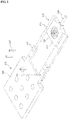
- FIG. 1 is a perspective view showing a long window apparatus according to an embodiment
- FIG. 2 is a view showing the lung window apparatus according to an embodiment when it is separated
- FIG. 3 shows a front view and a bottom view of the lung window apparatus according to an embodiment
- FIG. 4 shows a vertical cross-sectional view of the lung window apparatus according to an embodiment.
- a lung window apparatus may include an open window 100, a suction tube 102, and a tilting mount seat 104.
- the open window has a conical shape with open top and bottom and a diameter is increased from its upper part to its lower part.
- the open window 100 is brought in contact with a lung tissue on the bottom and a cover glass seat 106 is placed over the open window 100.
- a cover glass 110 is placed on the cover glass seat 106 and an objective lens 120 is placed over the cover glass 110.
- the suction tube 102 extends to a suction device (not shown) from a side of the open window 100.
- a cross-section of a lung tissue is brought in contact with the bottom of the open window 100, the cover glass 110 is placed over the open window 100, and the suction tube 102 is placed on a side of the open window 100, so it is possible to keep the inside of the open window 100 vacuum when obtaining an image.
- the tilting mount seat 104 extends from a side of the open window 100 and has a plurality of fastening holes 130, and a tilting mount 140 is coupled through at least some of the fastening holes 130.
- the tilting mount 140 is a kinematic tilting mount and maintains the lung window apparatus and the objective lens 120 in parallel by adjusting the angle of the lung window apparatus.
- the lung window apparatus may be provided by combining first plate 200 and a second plate 202, which are individual parts, with each other.
- the lung window apparatus comprising the tilting mount seat 104 and the open window 100 by putting the first plate 200 and the second plate 220 such that first protrusions 212 formed on a side of a first body 210 of the first plate 200 and second protrusions 222 formed on a side of a second body 220 of the second plate overlap each other, and then fastening the plates with bolts 230.
- the open window 100 is formed in the first body 210 and the tilting mount seat 104 is formed in the second body 220.
- the first protrusions 212 are smaller in thickness than the first body 220 and the second protrusions 222 are smaller in thickness than the second body 220.
- the first body 210 and the second body 220 may be the same in thickness, and the entire thickness when the first protrusions 212 and the second protrusions 222 overlap each other may be the same as the thickness of the first body 210 and the second body 220.
- the first plate 200 and the second plate 202 have steps, and when the first protrusions 212 and the second protrusion 222 overlap each other, the entire thickness is uniform.
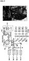
- FIG. 5 is a view showing the configuration of a confocal microscope system and arrangement of the lung window apparatus and the objective lens according to an embodiment.
- a process of obtaining an image according to the embodiment is as follows.
- the angle of the lung window apparatus is adjusted using the tilting mount 140 placed on the tilting mount seat 104 of the lung window apparatus.
- laser beams having a plurality of wavelengths are radiated to a lung tissue through the open window 100 of the lung window apparatus.
- a fluorescent signal excited in the lung tissue is detected through a detector.
- the confocal microscopic system includes four laser sources 500-1 to 500-4 respectively four wavelengths of 405nm, 488nm, 561nm, and 640nm within the visible light band, a polygonal rotation mirror 502, and a galvanometer mirror 504, and generates an XY raster scanning pattern, using these components.
- the confocal microscopic system may comprise a plurality of neutral density filters ND, mirrors M, and Dichroic beam splitters DBS, and beam pass filters BPF and photomultiplier tubes for detecting a fluorescent signal excited in a lung tissue.
- An optical system was designed to have an observation view of 250 ⁇ 250 ⁇ m 2 at the focus when using a ⁇ 40 objective lens (LUCPlanFL, NA0.6; Olympus) and a fluorescent signal was detected and processed by photomultiplier tubes individually and frame grabbers (Matrox, SOLIOS) that are provided for wavelengths such that 2D images having cellular-level resolution and being able to be sectioned in the Z-axial direction could be obtained at a speed of 30 sheets per second.
- LOCPlanFL ⁇ 40 objective lens
- NA0.6 opticallympus
- the lung window apparatus By attaching the lung window apparatus according to an embodiment to the confocal microscope system and radiating laser beams to a lung tissue through an objective lens, it is possible to obtaining cellular-level images in real time through excited fluorescent signals.
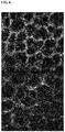
- FIG. 6 is a view showing a lung tissue image obtained using a microaspiration-based lung window apparatus and a confocal microscope system according to an embodiment.
- a lung tissue has a pulmonary alveolus and a capillary vessel surrounding the pulmonary alveolus and the capillary vessel has a vascular endothelial cell and a basement membrane covering the vascular endothelial cell.
- a black circular pulmonary alveoli and a capillary vessel (red in FIG. 6A and green in FIG. 6B ) composed of vascular endothelial cells surrounding the lungs are found.
- nuclei green in FIG. 6B .
- type I pulmonary cells type II pulmonary alveoli
- nuclei of macrophages around the pulmonary cells could be found.
- FIG. 7 is a view showing an image obtained by continuously imaging movement of erythrocyte after injecting FITC-Dextran into a C57BL6/J mouse obtained using a microaspiration-based lung window apparatus and a confocal microscope system according to an embodiment.
- An image for observing movement of erythrocyte and leukocyte was checked in consideration of influence on cells in a lung tissue due to microaspiration.
- An image of erythrocyte contrasted by black was obtained by injecting FITC-Dextran into a blood vessel of the C57BL6/J mouse, and as in FIG. 7 , it was found that movement of the erythrocyte was continued and was not influenced by microaspiration.
- FIG. 8 is a view showing an image obtained by continuously imaging movement of leukocyte in the LysM-GFP mouse obtained using a microaspiration-based lung window apparatus and a confocal microscope system according to an embodiment.
- the apparatus was useful for low-invasive and microscopic access to a lung tissue of an animal model without interfering with physiological circulation. Further, it was found that the apparatus was suitable for securing stable images of lung parenchyma and blood vessels and obtaining images for finding out interaction of cells and single cellular-level movement.
Landscapes
- Health & Medical Sciences (AREA)
- Life Sciences & Earth Sciences (AREA)
- Physics & Mathematics (AREA)
- Engineering & Computer Science (AREA)
- General Health & Medical Sciences (AREA)
- Surgery (AREA)
- Biomedical Technology (AREA)
- Heart & Thoracic Surgery (AREA)
- Medical Informatics (AREA)
- Molecular Biology (AREA)
- Pathology (AREA)
- Animal Behavior & Ethology (AREA)
- Biophysics (AREA)
- Public Health (AREA)
- Veterinary Medicine (AREA)
- Optics & Photonics (AREA)
- Chemical & Material Sciences (AREA)
- Analytical Chemistry (AREA)
- General Physics & Mathematics (AREA)
- Multimedia (AREA)
- Physiology (AREA)
- Pulmonology (AREA)
- Microscoopes, Condenser (AREA)
- Nuclear Medicine, Radiotherapy & Molecular Imaging (AREA)
- Radiology & Medical Imaging (AREA)
- Investigating, Analyzing Materials By Fluorescence Or Luminescence (AREA)
Abstract
Description
- This application claims priority from Korean Patent Application No.
10-2015-0123216, filed on August 31, 2015 - The present disclosure relates to a microaspiration-based lung window apparatus for obtaining a microscopic image of a lung tissue in vivo and a method for obtaining an image using the same.
- A confocal laser scanning microscope using fluorescent signals is used to observe cellular-level and molecular-level phenomenon.
- Unlike other tissues, the pulmonary system periodically moves due to the respiration process and the beating of the heart close to it, thus due to such motion artifacts it is difficult to obtain accurate images when wishing to obtain microscopic images.
- Due to this limit, most molecular biological studies are performed in the process of extracting, fixing, and then observing tissues. However, it is difficult to find out, in living animals, changes in blood vessels, or changes or interaction of blood vessels, tissue cells in lung parenchyma, and circulating cells including erythrocytes, leukocytes, and thrombocyte.
- Accordingly, it became an important subject to find out interaction between cells and molecular-level structures while physiologically maintaining respiration and circulation of living animals.
- To this end, it is required to develop an imaging window that allows for observing a molecular biological mechanism that occurs in a lung system and blood vessels in vivo, and can overcome a motion-artifact of microscopic images obtained through a confocal microscope.
- In order to solve these problems in the related art, the present disclosure provides a microaspiration-based lung window apparatus for obtaining a microscopic image of an in vivo lung tissue and a method for obtaining an image using the same, the apparatus and method being able to stably obtain cellular-level and molecular-level microscopic images of a lung tissue in vivo while physiologically maintaining and not interfering with respiration and circulation of an animal.
- According to an embodiment, there is provided a microaspiration-based lung window apparatus for obtaining a microscopic image of a lung tissue in vivo, the apparatus comprising: an open window configured to open in upper and lower parts thereof, have a cover glass placed on the upper part thereof, and have a lung tissue brought in contact with the lower part thereof;
a suction tube configured to extend to a suction device from a side of the open window and make the inside of the open window vacuum; and a tilting mount seat, configured to extend from a side of the open window, in which a tilting mount is placed to maintain the cover glass and an objective lens of a confocal microscope system in parallel. - According to an embodiment, there is provided a microaspiration-based lung window apparatus for obtaining a microscopic image of a lung tissue in vivo, the apparatus consisting of: an open window configured to open in upper and lower parts thereof, have a cover glass placed on the upper part thereof, and have a lung tissue brought in contact with the lower part thereof;
a suction tube configured to extend to a suction device from a side of the open window and make the inside of the open window vacuum; and a tilting mount seat, configured to extend from a side of the open window, in which a tilting mount is placed to maintain the cover glass and an objective lens of a confocal microscope system in parallel. - According to an embodiment, there is provided a microaspiration-based lung window apparatus for obtaining a microscopic image of a lung tissue in vivo, the apparatus essentially consisting of: an open window configured to open in upper and lower parts thereof, have a cover glass placed on the upper part thereof, and have a lung tissue brought in contact with the lower part thereof;
a suction tube configured to extend to a suction device from a side of the open window and make the inside of the open window vacuum; and a tilting mount seat, configured to extend from a side of the open window, in which a tilting mount is placed to maintain the cover glass and an objective lens of a confocal microscope system in parallel. - The open window may have a conical shape of which a diameter is increased from its upper part to its lower part.
- The tilting mount seat may have a plurality of fastening holes for coupling the tilting mount.
- The open window and the suction tube are formed in a first plate which has a first body and first protrusions having a step with respect to the first body and protrudes from sides of the first body, and
the tilting mount seat is formed in a second plate which has a second body and second protrusions having a step with respect to the second body and joining with the first protrusions. - According to another aspect, there is provided a microaspiration-based lung window apparatus for obtaining a microscopic image of an lung tissue in vivo, the apparatus comprising: a first plate in which an open window and a suction tube are formed, wherein the open window is configured to open in upper and lower parts thereof, have a cover glass placed on the upper part thereof, and have a lung tissue brought in contact with the lower part thereof, wherein the suction tube is configured to extend to a suction device from a side of the open window and make the inside of the open window vacuum; and a second plate, which is configured to join with the first plate, where there is formed a tilting mount seat in which a tilting mount is placed to maintain the cover glass and an objective lens of a confocal microscope system in parallel.
- According to another aspect, there is provided a microaspiration-based lung window apparatus for obtaining a microscopic image of an lung tissue in vivo, the apparatus consisting of: a first plate in which an open window and a suction tube are formed, wherein the open window is configured to open in upper and lower parts thereof, have a cover glass placed on the upper part thereof, and have a lung tissue brought in contact with the lower part thereof, wherein the suction tube is configured to extend to a suction device from a side of the open window and make the inside of the open window vacuum; and a second plate, which is configured to join with the first plate, where there is formed a tilting mount seat in which a tilting mount is placed to maintain the cover glass and an objective lens of a confocal microscope system in parallel.
- According to another aspect, there is provided a microaspiration-based lung window apparatus for obtaining a microscopic image of an lung tissue in vivo, the apparatus essentially consisting of: a first plate in which an open window and a suction tube are formed, wherein the open window is configured to open in upper and lower parts thereof, have a cover glass placed on the upper part thereof, and have a lung tissue brought in contact with the lower part thereof, wherein the suction tube is configured to extend to a suction device from a side of the open window and make the inside of the open window vacuum; and a second plate, which is configured to join with the first plate, where there is formed a tilting mount seat in which a tilting mount is placed to maintain the cover glass and an objective lens of a confocal microscope system in parallel.
- According to another aspect, there is provided a method of obtaining an image using a confocal microscope system and a microscopic aspiration-based lung window apparatus, the method comprising: adjusting the angle of the lung window apparatus by using a tilting mount placed on a tilting mount seat of the lung window apparatus; radiating laser beams having a plurality of wavelengths to a lung tissue through an open window of the lung window apparatus, wherein a cover glass is placed over the upper part of the open window, the lung tissue is brought in contact with the lower part of the open window, a suction tube extending to a suction device is formed on a side of the open window, so as to keep the inside of the open window vacuum; and detecting a fluorescent signal excited in the lung tissue, wherein the cover glass placed over the open window and an objective lens of the confocal microscope system are maintained in parallel in a respiration or circulation process by adjusting the angle of the tilting mount.
- According to another aspect, there is provided a method of obtaining an image using a confocal microscope system and a microscopic aspiration-based lung window apparatus, the method consisting of: adjusting the angle of the lung window apparatus by using a tilting mount placed on a tilting mount seat of the lung window apparatus; radiating laser beams having a plurality of wavelengths to a lung tissue through an open window of the lung window apparatus, wherein a cover glass is placed over the upper part of the open window, the lung tissue is brought in contact with the lower part of the open window, a suction tube extending to a suction device is formed on a side of the open window, so as to keep the inside of the open window vacuum; and detecting a fluorescent signal excited in the lung tissue, wherein the cover glass placed over the open window and an objective lens of the confocal microscope system are maintained in parallel in a respiration or circulation process by adjusting the angle of the tilting mount.
- According to another aspect, there is provided a method of obtaining an image using a confocal microscope system and a microscopic aspiration-based lung window apparatus, the method essentially consisting of: adjusting the angle of the lung window apparatus by using a tilting mount placed on a tilting mount seat of the lung window apparatus; radiating laser beams having a plurality of wavelengths to a lung tissue through an open window of the lung window apparatus, wherein a cover glass is placed over the upper part of the open window, the lung tissue is brought in contact with the lower part of the open window, a suction tube extending to a suction device is formed on a side of the open window, so as to keep the inside of the open window vacuum; and detecting a fluorescent signal excited in the lung tissue, wherein the cover glass placed over the open window and an objective lens of the confocal microscope system are maintained in parallel in a respiration or circulation process by adjusting the angle of the tilting mount.
- The term 'comprising' used herein have the same meaning as terms 'including' or 'characterized by', not excluding additional non-stated apparatuses, components, or steps in an apparatus or a method. The term 'consisting of' excludes additional elements, steps, or components not specifically stated. The term 'essentially consisting of' means including elements, components, or steps that do not actually influence basic characteristics in addition to stated elements, components, or steps in an apparatus or a method.
- According to the present disclosure, an open window that is attached to a lung tissue and placed close to an object lens and a seat that extends from the open window and on which a tilting mount is mounted are provided, and the open window and the objective lens can be maintained in parallel during respiration and circulation on an animal, so it is possible to obtain stable images.
-
-
FIG. 1 is a perspective view showing a lung window apparatus according to a preferred embodiment of the present invention, -
FIG. 2 is a view showing the lung window apparatus according to an embodiment of the present invention when it is separated, -
FIG. 3 shows a front view and a bottom view of the lung window apparatus according to an embodiment, -
FIG. 4 shows a vertical cross-sectional view of the lung window apparatus according to an embodiment, -
FIG. 5 is a view showing arrangement of a confocal microscope system, the lung window apparatus, and an objective lens according to an embodiment, -
FIG. 6 is a view showing a lung tissue image obtained using a microaspiration-based lung window apparatus and a confocal microscope system according to an embodiment, -
FIG. 7 is a view showing an image obtained by continuously imaging movement of erythrocyte after injecting FITC-Dextran into a C57BL6/J mouse obtained using a microaspiration-based lung window apparatus and a confocal microscope system according to an embodiment, and -
FIG. 8 is a view showing an image obtained by continuously imaging movement of leukocyte in the C57BL6/J mouse obtained using a microaspiration-based lung window apparatus and a confocal microscope system according to an embodiment. - The present disclosure may be modified in various ways and implemented by various exemplary embodiments, so that specific exemplary embodiments are shown in the drawings and will be described in detail.
- However, it is to be understood that the present disclosure is not limited to the specific exemplary embodiments, but includes all modifications, equivalents, and substitutions included in the spirit and the scope of the present disclosure. Reference numerals are assigned to reference components in the following description of drawings.
- Hereinafter, exemplary embodiments will be described in detail with reference to the accompanying drawings.
-
FIG. 1 is a perspective view showing a long window apparatus according to an embodiment,FIG. 2 is a view showing the lung window apparatus according to an embodiment when it is separated,FIG. 3 shows a front view and a bottom view of the lung window apparatus according to an embodiment, andFIG. 4 shows a vertical cross-sectional view of the lung window apparatus according to an embodiment. - Referring to
FIGS. 1 to 4 , a lung window apparatus according to an embodiment may include anopen window 100, asuction tube 102, and atilting mount seat 104. - The open window has a conical shape with open top and bottom and a diameter is increased from its upper part to its lower part.
- The
open window 100 is brought in contact with a lung tissue on the bottom and acover glass seat 106 is placed over theopen window 100. - When an image is obtained, a
cover glass 110 is placed on thecover glass seat 106 and anobjective lens 120 is placed over thecover glass 110. - The
suction tube 102 extends to a suction device (not shown) from a side of theopen window 100. - A cross-section of a lung tissue is brought in contact with the bottom of the
open window 100, thecover glass 110 is placed over theopen window 100, and thesuction tube 102 is placed on a side of theopen window 100, so it is possible to keep the inside of theopen window 100 vacuum when obtaining an image. - The
tilting mount seat 104 extends from a side of theopen window 100 and has a plurality offastening holes 130, and atilting mount 140 is coupled through at least some of thefastening holes 130. - In the embodiment, the
tilting mount 140 is a kinematic tilting mount and maintains the lung window apparatus and theobjective lens 120 in parallel by adjusting the angle of the lung window apparatus. - When the
objective lent 120 and thecover glass 110 placed over theopen window 100 are maintained in parallel by adjusting the angle of the lung window apparatus through thekinematic tilting mount 140, movement of the lung window apparatus can be restricted even with respiration and circulation physiologically maintained, so images can be stably obtained. - According to an embodiment, the lung window apparatus may be provided by combining
first plate 200 and asecond plate 202, which are individual parts, with each other. - Referring to
FIG. 2 , it is possible to provide the lung window apparatus comprising thetilting mount seat 104 and theopen window 100 by putting thefirst plate 200 and thesecond plate 220 such thatfirst protrusions 212 formed on a side of afirst body 210 of thefirst plate 200 andsecond protrusions 222 formed on a side of asecond body 220 of the second plate overlap each other, and then fastening the plates withbolts 230. - The
open window 100 is formed in thefirst body 210 and thetilting mount seat 104 is formed in thesecond body 220. - According to the embodiment, the
first protrusions 212 are smaller in thickness than thefirst body 220 and thesecond protrusions 222 are smaller in thickness than thesecond body 220. - Preferably, the
first body 210 and thesecond body 220 may be the same in thickness, and the entire thickness when thefirst protrusions 212 and thesecond protrusions 222 overlap each other may be the same as the thickness of thefirst body 210 and thesecond body 220. - The
first plate 200 and thesecond plate 202 have steps, and when thefirst protrusions 212 and thesecond protrusion 222 overlap each other, the entire thickness is uniform. -
FIG. 5 is a view showing the configuration of a confocal microscope system and arrangement of the lung window apparatus and the objective lens according to an embodiment. - A process of obtaining an image according to the embodiment is as follows.
- The angle of the lung window apparatus is adjusted using the tilting
mount 140 placed on the tiltingmount seat 104 of the lung window apparatus. - As in
FIG. 5 , laser beams having a plurality of wavelengths are radiated to a lung tissue through theopen window 100 of the lung window apparatus. - A fluorescent signal excited in the lung tissue is detected through a detector.
- Referring to
FIG. 5 , the confocal microscopic system according to the embodiment includes four laser sources 500-1 to 500-4 respectively four wavelengths of 405nm, 488nm, 561nm, and 640nm within the visible light band, apolygonal rotation mirror 502, and agalvanometer mirror 504, and generates an XY raster scanning pattern, using these components. - The confocal microscopic system may comprise a plurality of neutral density filters ND, mirrors M, and Dichroic beam splitters DBS, and beam pass filters BPF and photomultiplier tubes for detecting a fluorescent signal excited in a lung tissue.
- Images of a lung tissue were obtained from an actual animal model, using the confocal optical microscope using the microaspiration-based lung window apparatus of the present disclosure.
- An optical system was designed to have an observation view of 250×250 µm2 at the focus when using a ×40 objective lens (LUCPlanFL, NA0.6; Olympus) and a fluorescent signal was detected and processed by photomultiplier tubes individually and frame grabbers (Matrox, SOLIOS) that are provided for wavelengths such that 2D images having cellular-level resolution and being able to be sectioned in the Z-axial direction could be obtained at a speed of 30 sheets per second.
- By attaching the lung window apparatus according to an embodiment to the confocal microscope system and radiating laser beams to a lung tissue through an objective lens, it is possible to obtaining cellular-level images in real time through excited fluorescent signals.
-
FIG. 6 is a view showing a lung tissue image obtained using a microaspiration-based lung window apparatus and a confocal microscope system according to an embodiment. - A lung tissue has a pulmonary alveolus and a capillary vessel surrounding the pulmonary alveolus and the capillary vessel has a vascular endothelial cell and a basement membrane covering the vascular endothelial cell.
- In order to check first the structure of such a lung, observation was performed on the lungs of a Tie2-GFP mouse having a green fluorescent signal expressed in a Tie2 receptor and an Actin-DsRed & Histone-GFP having a red fluorescent signal expressed in an Actin filament and a green fluorescent signal expressed in Histone, using a confocal microscope system and the lung window apparatus according to the embodiment.
- As described above, a black circular pulmonary alveoli and a capillary vessel (red in
FIG. 6A and green inFIG. 6B ) composed of vascular endothelial cells surrounding the lungs are found. - Further, in a lung tissue, nuclei (green in
FIG. 6B ) of type I pulmonary cells, type II pulmonary alveoli, and nuclei of macrophages around the pulmonary cells could be found. -
FIG. 7 is a view showing an image obtained by continuously imaging movement of erythrocyte after injecting FITC-Dextran into a C57BL6/J mouse obtained using a microaspiration-based lung window apparatus and a confocal microscope system according to an embodiment. - An image for observing movement of erythrocyte and leukocyte was checked in consideration of influence on cells in a lung tissue due to microaspiration. An image of erythrocyte contrasted by black was obtained by injecting FITC-Dextran into a blood vessel of the C57BL6/J mouse, and as in
FIG. 7 , it was found that movement of the erythrocyte was continued and was not influenced by microaspiration. -
FIG. 8 is a view showing an image obtained by continuously imaging movement of leukocyte in the LysM-GFP mouse obtained using a microaspiration-based lung window apparatus and a confocal microscope system according to an embodiment. - In order to observe movement of leukocyte, injecting TMR-Dextran into a LysM-GFP mouse in which a green fluorescent signal was expressed in LysM protein to show blood vessels with red was performed and then tracing the movement path of the LysM in the blood vessels was performed. As shown in
FIG. 8 , it was found that movement of leukocyte was also continued and was not influenced by microaspiration. - As described above, by using the lung window apparatus according to the embodiment, it was found that the apparatus was useful for low-invasive and microscopic access to a lung tissue of an animal model without interfering with physiological circulation. Further, it was found that the apparatus was suitable for securing stable images of lung parenchyma and blood vessels and obtaining images for finding out interaction of cells and single cellular-level movement.
- Hereinabove, although the present disclosure is described by specific matters such as concrete components, and the like, embodiments, and drawings, they are provided only for assisting in the entire understanding of the present disclosure. Therefore, the present disclosure is not limited to the embodiments. Various modifications and changes may be made by those skilled in the art to which the present disclosure pertains from this description. Therefore, the sprit of the present disclosure should not be limited to the above-described embodiments, and the following claims as well as all modified equally or equivalently to the claims are intended to fall within the scope and spirit of the disclosure.
Claims (7)
- A microaspiration-based lung window apparatus for obtaining a microscopic image of a lung tissue in vivo, the apparatus comprising:an open window configured to open in upper and lower parts thereof, have a cover glass placed on the upper part thereof, and have a lung tissue brought in contact with the lower part thereof;a suction tube configured to extend to a suction device from a side of the open window and make the inside of the open window vacuum; anda tilting mount seat, configured to extend from a side of the open window, in which a tilting mount is placed to maintain the cover glass and an objective lens of a confocal microscope system in parallel.
- The apparatus of claim 1, wherein the open window has a conical shape of which a diameter is increased from its upper part to its lower part.
- The apparatus of claim 1, wherein the tilting mount seat has a plurality of fastening holes for coupling the tilting mount.
- The apparatus of claim 1, wherein the open window and the suction tube are formed in a first plate which has a first body and first protrusions having a step with respect to the first body and protrudes from sides of the first body, and
the tilting mount seat is formed in a second plate which has a second body and second protrusions having a step with respect to the second body and joining with the first protrusions. - A microaspiration-based lung window apparatus for obtaining a microscopic image of a lung tissue in vivo, the apparatus comprising:a first plate in which an open window and a suction tube are formed, wherein the open window is configured to open in upper and lower parts thereof, have a cover glass placed on the upper part thereof, and have a lung tissue brought in contact with the lower part thereof, wherein the suction tube is configured to extend to a suction device from a side of the open window and make the inside of the open window vacuum; anda second plate, which is configured to join with the first plate, where there is formed a tilting mount seat in which a tilting mount is placed to maintain the cover glass and an objective lens of a confocal microscope system in parallel.
- The apparatus of claim 5, wherein the first plate has a first body where the open window and the suction tube are formed and first protrusions having a step with respect to the first body and protruding from sides of the first body, and
the second plate has a second body where the tilting mount seat is formed and second protrusions having a step with respect to the second body and joining with the first protrusions. - A method of obtaining an image using a confocal microscope system and a microscopic aspiration-based lung window apparatus, the method comprising:adjusting the angle of the lung window apparatus by using a tilting mount placed on a tilting mount seat of the lung window apparatus;radiating laser beams having a plurality of wavelengths to a lung tissue through an open window of the lung window apparatus, wherein a cover glass is placed over the upper part of the open window, the lung tissue is brought in contact with the lower part of the open window, a suction tube extending to a suction device is formed on a side of the open window, so as to keep the inside of the open window vacuum; anddetecting a fluorescent signal excited in the lung tissue,wherein the cover glass placed over the open window and an objective lens of the confocal microscope system are maintained in parallel in a respiration or circulation process by adjusting the angle of the tilting mount.
Applications Claiming Priority (2)
| Application Number | Priority Date | Filing Date | Title |
|---|---|---|---|
| KR1020150123216A KR101743283B1 (en) | 2015-08-31 | 2015-08-31 | Lung window apparatus based on micro-suction for in vivo microscopic imaging of lung tissue and method for obtaining image using the same |
| PCT/KR2016/009720 WO2017039316A1 (en) | 2015-08-31 | 2016-08-31 | Microaspiration-based lung window apparatus for obtaining microscopic image of in vivo lung tissue and method for obtaining image using same |
Publications (4)
| Publication Number | Publication Date |
|---|---|
| EP3345546A1 true EP3345546A1 (en) | 2018-07-11 |
| EP3345546A4 EP3345546A4 (en) | 2019-05-29 |
| EP3345546B1 EP3345546B1 (en) | 2023-10-04 |
| EP3345546C0 EP3345546C0 (en) | 2023-10-04 |
Family
ID=58188002
Family Applications (1)
| Application Number | Title | Priority Date | Filing Date |
|---|---|---|---|
| EP16842282.2A Active EP3345546B1 (en) | 2015-08-31 | 2016-08-31 | Microaspiration-based lung window apparatus for obtaining microscopic image of in vivo lung tissue |
Country Status (6)
| Country | Link |
|---|---|
| US (1) | US10437035B2 (en) |
| EP (1) | EP3345546B1 (en) |
| JP (1) | JP6630831B2 (en) |
| KR (1) | KR101743283B1 (en) |
| CN (1) | CN108601555B (en) |
| WO (1) | WO2017039316A1 (en) |
Families Citing this family (2)
| Publication number | Priority date | Publication date | Assignee | Title |
|---|---|---|---|---|
| HK1254295A1 (en) | 2015-11-23 | 2019-07-19 | 默克专利股份有限公司 | Anti-alpha-v integrin antibody for the treatment of fibrosis and/or fibrotic disorders |
| CN109030438A (en) * | 2018-07-06 | 2018-12-18 | 广州蓝勃生物科技有限公司 | A kind of optical path mould group for multi-wavelength fluorescence detection |
Family Cites Families (26)
| Publication number | Priority date | Publication date | Assignee | Title |
|---|---|---|---|---|
| JPS5421752A (en) * | 1977-07-19 | 1979-02-19 | Toshiba Corp | Stage device for microscopes |
| JP3214805B2 (en) * | 1995-07-17 | 2001-10-02 | シャープ株式会社 | Objective lens adjustment mechanism |
| US5907425A (en) * | 1995-12-19 | 1999-05-25 | The Board Of Trustees Of The Leland Stanford Junior University | Miniature scanning confocal microscope |
| JP4564664B2 (en) * | 1999-02-17 | 2010-10-20 | ルーシド インコーポレーテッド | Cassette for forming optical thin sections of retained tissue specimens |
| US20060100666A1 (en) * | 2000-04-20 | 2006-05-11 | Pulmosonix Pty. Ltd. | Apparatus and method for lung analysis |
| US6414779B1 (en) * | 2000-11-30 | 2002-07-02 | Opeical Biopsy Technologies, Inc. | Integrated angled-dual-axis confocal scanning endoscopes |
| US6898006B2 (en) * | 2001-12-26 | 2005-05-24 | Olympus Optical Co., Ltd. | Microscope |
| CN1439878A (en) * | 2003-01-17 | 2003-09-03 | 陕西超英生物医学研究开发有限公司 | Autoantibody detection tissue chip |
| CN1253716C (en) * | 2004-01-08 | 2006-04-26 | 中南大学湘雅医学院肿瘤研究所 | Tissue chip used for tumour early stage diagnosis and preparation device |
| WO2005107579A1 (en) | 2004-05-11 | 2005-11-17 | Koninklijke Philips Electronics N.V. | Measurement head for non-invasive blood analysis |
| US7945077B2 (en) * | 2005-11-30 | 2011-05-17 | Lawrence Livermore National Security, Llc | Hyperspectral microscope for in vivo imaging of microstructures and cells in tissues |
| JP5268282B2 (en) * | 2007-05-15 | 2013-08-21 | 有限会社 楠屋 | Method for observing and acquiring histological image inside the individual |
| JP4996977B2 (en) * | 2007-05-25 | 2012-08-08 | オリンパス株式会社 | Stabilizer and biological observation apparatus |
| US7906076B2 (en) * | 2007-07-02 | 2011-03-15 | University Of Massachusetts | Method and apparatus for biopsy sample processing |
| US8206315B2 (en) * | 2008-09-30 | 2012-06-26 | Suros Surgical Systems, Inc. | Real-time pathology |
| KR101042505B1 (en) * | 2008-11-27 | 2011-06-16 | 현대제철 주식회사 | Specimen Holder of Scanning Electron Microscope |
| CN101872064B (en) * | 2009-04-24 | 2012-07-04 | 陈亮嘉 | Linear multi-wavelength confocal microscope module and its confocal microscopy method and system |
| CN102297873A (en) * | 2011-05-03 | 2011-12-28 | 杭州一二八医院 | Method for identifying cancer cell images by soft X-ray microscopic imaging |
| CN202075487U (en) * | 2011-06-03 | 2011-12-14 | 江南大学 | Self parallel reading microscope |
| JP5930364B2 (en) * | 2011-11-28 | 2016-06-08 | 国立大学法人京都大学 | Biological sample fixator |
| WO2013109624A2 (en) * | 2012-01-17 | 2013-07-25 | Mayo Foundation For Medical Education And Research | Probe-based confocal laser endomicroscopy |
| JP6037732B2 (en) * | 2012-09-03 | 2016-12-07 | オリンパス株式会社 | Immersion holder, observation site fixing device, and microscope |
| CN103202696B (en) * | 2013-03-06 | 2014-12-17 | 王胜昱 | Modeling method for detecting lung diseases through expiratory air on basis of aerosol |
| US10007102B2 (en) * | 2013-12-23 | 2018-06-26 | Sakura Finetek U.S.A., Inc. | Microscope with slide clamping assembly |
| US20160095532A1 (en) * | 2014-10-03 | 2016-04-07 | Weinberg Medical Physics Llc | Method and components for in vivo determination of malignancy |
| WO2016200985A1 (en) * | 2015-06-08 | 2016-12-15 | Trustees Of Tufts College | Imaging system to characterize dynamic changes in cell and particle characteristics |
-
2015
- 2015-08-31 KR KR1020150123216A patent/KR101743283B1/en active Active
-
2016
- 2016-08-31 US US15/756,478 patent/US10437035B2/en active Active
- 2016-08-31 WO PCT/KR2016/009720 patent/WO2017039316A1/en not_active Ceased
- 2016-08-31 CN CN201680062597.XA patent/CN108601555B/en active Active
- 2016-08-31 JP JP2018530459A patent/JP6630831B2/en active Active
- 2016-08-31 EP EP16842282.2A patent/EP3345546B1/en active Active
Also Published As
| Publication number | Publication date |
|---|---|
| WO2017039316A1 (en) | 2017-03-09 |
| EP3345546A4 (en) | 2019-05-29 |
| EP3345546B1 (en) | 2023-10-04 |
| EP3345546C0 (en) | 2023-10-04 |
| CN108601555A (en) | 2018-09-28 |
| KR20170025998A (en) | 2017-03-08 |
| US20180246311A1 (en) | 2018-08-30 |
| JP2018526688A (en) | 2018-09-13 |
| JP6630831B2 (en) | 2020-01-15 |
| KR101743283B1 (en) | 2017-06-02 |
| WO2017039316A8 (en) | 2018-03-22 |
| CN108601555B (en) | 2021-01-29 |
| US10437035B2 (en) | 2019-10-08 |
Similar Documents
| Publication | Publication Date | Title |
|---|---|---|
| EP2770899B1 (en) | Tissue and cellular imaging | |
| JP6346096B2 (en) | Cell observation apparatus and cell observation method | |
| US20190072562A1 (en) | System and method for determination of ligand-target binding by multi-photon fluorescence anisotropy microscopy | |
| US10437035B2 (en) | Microaspiration-based lung window apparatus for obtaining microscopic image of in vivo lung tissue and method for obtaining image using same | |
| US11029504B2 (en) | Window apparatus for obtaining microscopic image of in vivo breast tissue and method for obtaining image using same | |
| EP3868282A1 (en) | Microscopic image acquisition system of in-vivo deep tissue and microscopic image providing method therefor | |
| KR101767339B1 (en) | Window apparatus and method for in vivo microscopic imaging of pancreatic tissue for obtaining image using the same | |
| Conci et al. | In vivo label-free tissue histology through a microstructured imaging window | |
| CN209847146U (en) | Multi-modal imaging system | |
| JP2005301065A (en) | Observation device | |
| WO2025184629A1 (en) | Kilohertz volumetric imaging of in vivo dynamics using squeezed light field microscopy | |
| KR101022803B1 (en) | Small animal imaging device for fluorescence and gamma ray imaging | |
| JP6722620B2 (en) | Cell state analyzer and analysis method | |
| Shao et al. | 3D myofibril imaging in live cardiomyocytes via hybrid SHG-TPEF microscopy | |
| Wood | Engineering Studies towards Simultaneous Imaging of Membrane Potential and Calcium Transients in Beating Hearts | |
| JP2008286883A (en) | Method for observing and acquiring histological image inside individual | |
| WO2008067525A2 (en) | Method and apparatus for measuring quantity of a fluorochrome in a biological environment | |
| Ramos-Gomes et al. | An Alternative Technique for Monitoring the Live Interaction of Monocytes and Tumor Cells with Nanoparticles in the Mouse Lung | |
| Almasian et al. | Axially swept dithered light-sheet microscope to reveal cardiac morphology | |
| Jung et al. | Intravital Imaging of Tumors | |
| CN104887318A (en) | Mini-type confocal microscope | |
| Singh et al. | Confocal imaging of intracellular calcium cycling in the intact heart | |
| KR20250109667A (en) | Systems and methods for rapid label-free imaging of biological tissues based on microscopy with ultraviolet single-plane illumination | |
| Yang et al. | In situ imaging of the mouse cochlea using two-photon microscopy | |
| Stender et al. | Motion compensation of optical mapping signals from rat heart slices |
Legal Events
| Date | Code | Title | Description |
|---|---|---|---|
| STAA | Information on the status of an ep patent application or granted ep patent |
Free format text: STATUS: THE INTERNATIONAL PUBLICATION HAS BEEN MADE |
|
| PUAI | Public reference made under article 153(3) epc to a published international application that has entered the european phase |
Free format text: ORIGINAL CODE: 0009012 |
|
| STAA | Information on the status of an ep patent application or granted ep patent |
Free format text: STATUS: REQUEST FOR EXAMINATION WAS MADE |
|
| 17P | Request for examination filed |
Effective date: 20180312 |
|
| AK | Designated contracting states |
Kind code of ref document: A1 Designated state(s): AL AT BE BG CH CY CZ DE DK EE ES FI FR GB GR HR HU IE IS IT LI LT LU LV MC MK MT NL NO PL PT RO RS SE SI SK SM TR |
|
| AX | Request for extension of the european patent |
Extension state: BA ME |
|
| DAV | Request for validation of the european patent (deleted) | ||
| DAX | Request for extension of the european patent (deleted) | ||
| A4 | Supplementary search report drawn up and despatched |
Effective date: 20190502 |
|
| RIC1 | Information provided on ipc code assigned before grant |
Ipc: A61B 5/00 20060101ALI20190425BHEP Ipc: G02B 21/00 20060101ALI20190425BHEP Ipc: A61B 5/08 20060101AFI20190425BHEP Ipc: G02B 21/36 20060101ALI20190425BHEP |
|
| STAA | Information on the status of an ep patent application or granted ep patent |
Free format text: STATUS: EXAMINATION IS IN PROGRESS |
|
| 17Q | First examination report despatched |
Effective date: 20220517 |
|
| GRAP | Despatch of communication of intention to grant a patent |
Free format text: ORIGINAL CODE: EPIDOSNIGR1 |
|
| STAA | Information on the status of an ep patent application or granted ep patent |
Free format text: STATUS: GRANT OF PATENT IS INTENDED |
|
| INTG | Intention to grant announced |
Effective date: 20230419 |
|
| GRAS | Grant fee paid |
Free format text: ORIGINAL CODE: EPIDOSNIGR3 |
|
| GRAA | (expected) grant |
Free format text: ORIGINAL CODE: 0009210 |
|
| STAA | Information on the status of an ep patent application or granted ep patent |
Free format text: STATUS: THE PATENT HAS BEEN GRANTED |
|
| AK | Designated contracting states |
Kind code of ref document: B1 Designated state(s): AL AT BE BG CH CY CZ DE DK EE ES FI FR GB GR HR HU IE IS IT LI LT LU LV MC MK MT NL NO PL PT RO RS SE SI SK SM TR |
|
| REG | Reference to a national code |
Ref country code: GB Ref legal event code: FG4D |
|
| REG | Reference to a national code |
Ref country code: CH Ref legal event code: EP |
|
| REG | Reference to a national code |
Ref country code: IE Ref legal event code: FG4D |
|
| REG | Reference to a national code |
Ref country code: DE Ref legal event code: R096 Ref document number: 602016083257 Country of ref document: DE |
|
| U01 | Request for unitary effect filed |
Effective date: 20231012 |
|
| U07 | Unitary effect registered |
Designated state(s): AT BE BG DE DK EE FI FR IT LT LU LV MT NL PT SE SI Effective date: 20231023 |
|
| PG25 | Lapsed in a contracting state [announced via postgrant information from national office to epo] |
Ref country code: GR Free format text: LAPSE BECAUSE OF FAILURE TO SUBMIT A TRANSLATION OF THE DESCRIPTION OR TO PAY THE FEE WITHIN THE PRESCRIBED TIME-LIMIT Effective date: 20240105 |
|
| PG25 | Lapsed in a contracting state [announced via postgrant information from national office to epo] |
Ref country code: IS Free format text: LAPSE BECAUSE OF FAILURE TO SUBMIT A TRANSLATION OF THE DESCRIPTION OR TO PAY THE FEE WITHIN THE PRESCRIBED TIME-LIMIT Effective date: 20240204 |
|
| PG25 | Lapsed in a contracting state [announced via postgrant information from national office to epo] |
Ref country code: ES Free format text: LAPSE BECAUSE OF FAILURE TO SUBMIT A TRANSLATION OF THE DESCRIPTION OR TO PAY THE FEE WITHIN THE PRESCRIBED TIME-LIMIT Effective date: 20231004 |
|
| PG25 | Lapsed in a contracting state [announced via postgrant information from national office to epo] |
Ref country code: IS Free format text: LAPSE BECAUSE OF FAILURE TO SUBMIT A TRANSLATION OF THE DESCRIPTION OR TO PAY THE FEE WITHIN THE PRESCRIBED TIME-LIMIT Effective date: 20240204 Ref country code: GR Free format text: LAPSE BECAUSE OF FAILURE TO SUBMIT A TRANSLATION OF THE DESCRIPTION OR TO PAY THE FEE WITHIN THE PRESCRIBED TIME-LIMIT Effective date: 20240105 Ref country code: ES Free format text: LAPSE BECAUSE OF FAILURE TO SUBMIT A TRANSLATION OF THE DESCRIPTION OR TO PAY THE FEE WITHIN THE PRESCRIBED TIME-LIMIT Effective date: 20231004 |
|
| PG25 | Lapsed in a contracting state [announced via postgrant information from national office to epo] |
Ref country code: RS Free format text: LAPSE BECAUSE OF FAILURE TO SUBMIT A TRANSLATION OF THE DESCRIPTION OR TO PAY THE FEE WITHIN THE PRESCRIBED TIME-LIMIT Effective date: 20231004 Ref country code: PL Free format text: LAPSE BECAUSE OF FAILURE TO SUBMIT A TRANSLATION OF THE DESCRIPTION OR TO PAY THE FEE WITHIN THE PRESCRIBED TIME-LIMIT Effective date: 20231004 Ref country code: NO Free format text: LAPSE BECAUSE OF FAILURE TO SUBMIT A TRANSLATION OF THE DESCRIPTION OR TO PAY THE FEE WITHIN THE PRESCRIBED TIME-LIMIT Effective date: 20240104 Ref country code: HR Free format text: LAPSE BECAUSE OF FAILURE TO SUBMIT A TRANSLATION OF THE DESCRIPTION OR TO PAY THE FEE WITHIN THE PRESCRIBED TIME-LIMIT Effective date: 20231004 |
|
| REG | Reference to a national code |
Ref country code: DE Ref legal event code: R097 Ref document number: 602016083257 Country of ref document: DE |
|
| PG25 | Lapsed in a contracting state [announced via postgrant information from national office to epo] |
Ref country code: CZ Free format text: LAPSE BECAUSE OF FAILURE TO SUBMIT A TRANSLATION OF THE DESCRIPTION OR TO PAY THE FEE WITHIN THE PRESCRIBED TIME-LIMIT Effective date: 20231004 |
|
| PG25 | Lapsed in a contracting state [announced via postgrant information from national office to epo] |
Ref country code: SK Free format text: LAPSE BECAUSE OF FAILURE TO SUBMIT A TRANSLATION OF THE DESCRIPTION OR TO PAY THE FEE WITHIN THE PRESCRIBED TIME-LIMIT Effective date: 20231004 |
|
| PG25 | Lapsed in a contracting state [announced via postgrant information from national office to epo] |
Ref country code: SM Free format text: LAPSE BECAUSE OF FAILURE TO SUBMIT A TRANSLATION OF THE DESCRIPTION OR TO PAY THE FEE WITHIN THE PRESCRIBED TIME-LIMIT Effective date: 20231004 Ref country code: SK Free format text: LAPSE BECAUSE OF FAILURE TO SUBMIT A TRANSLATION OF THE DESCRIPTION OR TO PAY THE FEE WITHIN THE PRESCRIBED TIME-LIMIT Effective date: 20231004 Ref country code: RO Free format text: LAPSE BECAUSE OF FAILURE TO SUBMIT A TRANSLATION OF THE DESCRIPTION OR TO PAY THE FEE WITHIN THE PRESCRIBED TIME-LIMIT Effective date: 20231004 Ref country code: CZ Free format text: LAPSE BECAUSE OF FAILURE TO SUBMIT A TRANSLATION OF THE DESCRIPTION OR TO PAY THE FEE WITHIN THE PRESCRIBED TIME-LIMIT Effective date: 20231004 |
|
| PLBE | No opposition filed within time limit |
Free format text: ORIGINAL CODE: 0009261 |
|
| STAA | Information on the status of an ep patent application or granted ep patent |
Free format text: STATUS: NO OPPOSITION FILED WITHIN TIME LIMIT |
|
| 26N | No opposition filed |
Effective date: 20240705 |
|
| U20 | Renewal fee for the european patent with unitary effect paid |
Year of fee payment: 9 Effective date: 20240829 |
|
| PG25 | Lapsed in a contracting state [announced via postgrant information from national office to epo] |
Ref country code: MC Free format text: LAPSE BECAUSE OF FAILURE TO SUBMIT A TRANSLATION OF THE DESCRIPTION OR TO PAY THE FEE WITHIN THE PRESCRIBED TIME-LIMIT Effective date: 20231004 |
|
| PG25 | Lapsed in a contracting state [announced via postgrant information from national office to epo] |
Ref country code: IE Free format text: LAPSE BECAUSE OF NON-PAYMENT OF DUE FEES Effective date: 20240831 |
|
| U20 | Renewal fee for the european patent with unitary effect paid |
Year of fee payment: 10 Effective date: 20250709 |
|
| PGFP | Annual fee paid to national office [announced via postgrant information from national office to epo] |
Ref country code: GB Payment date: 20250703 Year of fee payment: 10 |
|
| PGFP | Annual fee paid to national office [announced via postgrant information from national office to epo] |
Ref country code: CH Payment date: 20250901 Year of fee payment: 10 |
|
| PG25 | Lapsed in a contracting state [announced via postgrant information from national office to epo] |
Ref country code: CY Free format text: LAPSE BECAUSE OF FAILURE TO SUBMIT A TRANSLATION OF THE DESCRIPTION OR TO PAY THE FEE WITHIN THE PRESCRIBED TIME-LIMIT; INVALID AB INITIO Effective date: 20160831 |
|
| PG25 | Lapsed in a contracting state [announced via postgrant information from national office to epo] |
Ref country code: HU Free format text: LAPSE BECAUSE OF FAILURE TO SUBMIT A TRANSLATION OF THE DESCRIPTION OR TO PAY THE FEE WITHIN THE PRESCRIBED TIME-LIMIT; INVALID AB INITIO Effective date: 20160831 |