EP3345534B1 - User terminal and sleep management method - Google Patents
User terminal and sleep management method Download PDFInfo
- Publication number
- EP3345534B1 EP3345534B1 EP16842230.1A EP16842230A EP3345534B1 EP 3345534 B1 EP3345534 B1 EP 3345534B1 EP 16842230 A EP16842230 A EP 16842230A EP 3345534 B1 EP3345534 B1 EP 3345534B1
- Authority
- EP
- European Patent Office
- Prior art keywords
- user
- sleep
- home appliance
- state
- user terminal
- Prior art date
- Legal status (The legal status is an assumption and is not a legal conclusion. Google has not performed a legal analysis and makes no representation as to the accuracy of the status listed.)
- Active
Links
- 230000007958 sleep Effects 0.000 title claims description 744
- 238000007726 management method Methods 0.000 title claims description 124
- 230000029058 respiratory gaseous exchange Effects 0.000 claims description 50
- 238000012423 maintenance Methods 0.000 claims description 29
- 230000006698 induction Effects 0.000 claims description 28
- 230000004622 sleep time Effects 0.000 claims description 21
- 230000036385 rapid eye movement (rem) sleep Effects 0.000 claims description 13
- 230000004044 response Effects 0.000 claims description 8
- 230000001939 inductive effect Effects 0.000 claims description 5
- 238000004891 communication Methods 0.000 description 51
- 230000008667 sleep stage Effects 0.000 description 19
- 238000000034 method Methods 0.000 description 17
- 230000008569 process Effects 0.000 description 15
- 230000002618 waking effect Effects 0.000 description 13
- 230000007423 decrease Effects 0.000 description 11
- 230000008859 change Effects 0.000 description 9
- 230000001133 acceleration Effects 0.000 description 6
- 230000003247 decreasing effect Effects 0.000 description 5
- 230000008452 non REM sleep Effects 0.000 description 5
- 230000006870 function Effects 0.000 description 3
- 238000010295 mobile communication Methods 0.000 description 3
- 206010049816 Muscle tightness Diseases 0.000 description 2
- 206010062519 Poor quality sleep Diseases 0.000 description 2
- 230000002159 abnormal effect Effects 0.000 description 2
- 238000004458 analytical method Methods 0.000 description 2
- 239000013078 crystal Substances 0.000 description 2
- 230000000694 effects Effects 0.000 description 2
- 230000001815 facial effect Effects 0.000 description 2
- 238000005259 measurement Methods 0.000 description 2
- 238000012544 monitoring process Methods 0.000 description 2
- 230000004962 physiological condition Effects 0.000 description 2
- 230000003860 sleep quality Effects 0.000 description 2
- 201000010099 disease Diseases 0.000 description 1
- 208000037265 diseases, disorders, signs and symptoms Diseases 0.000 description 1
- 230000008451 emotion Effects 0.000 description 1
- 238000005516 engineering process Methods 0.000 description 1
- 230000007774 longterm Effects 0.000 description 1
- 238000012986 modification Methods 0.000 description 1
- 230000004048 modification Effects 0.000 description 1
- 230000010287 polarization Effects 0.000 description 1
- 238000012545 processing Methods 0.000 description 1
- 230000004461 rapid eye movement Effects 0.000 description 1
- 238000011160 research Methods 0.000 description 1
- 230000003068 static effect Effects 0.000 description 1
Images


Classifications
-
- H—ELECTRICITY
- H04—ELECTRIC COMMUNICATION TECHNIQUE
- H04L—TRANSMISSION OF DIGITAL INFORMATION, e.g. TELEGRAPHIC COMMUNICATION
- H04L12/00—Data switching networks
- H04L12/28—Data switching networks characterised by path configuration, e.g. LAN [Local Area Networks] or WAN [Wide Area Networks]
- H04L12/2803—Home automation networks
- H04L12/2816—Controlling appliance services of a home automation network by calling their functionalities
- H04L12/282—Controlling appliance services of a home automation network by calling their functionalities based on user interaction within the home
-
- A—HUMAN NECESSITIES
- A61—MEDICAL OR VETERINARY SCIENCE; HYGIENE
- A61B—DIAGNOSIS; SURGERY; IDENTIFICATION
- A61B5/00—Measuring for diagnostic purposes; Identification of persons
- A61B5/0002—Remote monitoring of patients using telemetry, e.g. transmission of vital signals via a communication network
- A61B5/0004—Remote monitoring of patients using telemetry, e.g. transmission of vital signals via a communication network characterised by the type of physiological signal transmitted
-
- A—HUMAN NECESSITIES
- A61—MEDICAL OR VETERINARY SCIENCE; HYGIENE
- A61B—DIAGNOSIS; SURGERY; IDENTIFICATION
- A61B5/00—Measuring for diagnostic purposes; Identification of persons
- A61B5/02—Detecting, measuring or recording pulse, heart rate, blood pressure or blood flow; Combined pulse/heart-rate/blood pressure determination; Evaluating a cardiovascular condition not otherwise provided for, e.g. using combinations of techniques provided for in this group with electrocardiography or electroauscultation; Heart catheters for measuring blood pressure
- A61B5/024—Detecting, measuring or recording pulse rate or heart rate
-
- A—HUMAN NECESSITIES
- A61—MEDICAL OR VETERINARY SCIENCE; HYGIENE
- A61B—DIAGNOSIS; SURGERY; IDENTIFICATION
- A61B5/00—Measuring for diagnostic purposes; Identification of persons
- A61B5/08—Detecting, measuring or recording devices for evaluating the respiratory organs
- A61B5/0816—Measuring devices for examining respiratory frequency
-
- A—HUMAN NECESSITIES
- A61—MEDICAL OR VETERINARY SCIENCE; HYGIENE
- A61B—DIAGNOSIS; SURGERY; IDENTIFICATION
- A61B5/00—Measuring for diagnostic purposes; Identification of persons
- A61B5/103—Detecting, measuring or recording devices for testing the shape, pattern, colour, size or movement of the body or parts thereof, for diagnostic purposes
- A61B5/11—Measuring movement of the entire body or parts thereof, e.g. head or hand tremor, mobility of a limb
- A61B5/1118—Determining activity level
-
- A—HUMAN NECESSITIES
- A61—MEDICAL OR VETERINARY SCIENCE; HYGIENE
- A61B—DIAGNOSIS; SURGERY; IDENTIFICATION
- A61B5/00—Measuring for diagnostic purposes; Identification of persons
- A61B5/48—Other medical applications
- A61B5/4806—Sleep evaluation
- A61B5/4809—Sleep detection, i.e. determining whether a subject is asleep or not
-
- A—HUMAN NECESSITIES
- A61—MEDICAL OR VETERINARY SCIENCE; HYGIENE
- A61B—DIAGNOSIS; SURGERY; IDENTIFICATION
- A61B5/00—Measuring for diagnostic purposes; Identification of persons
- A61B5/68—Arrangements of detecting, measuring or recording means, e.g. sensors, in relation to patient
- A61B5/6887—Arrangements of detecting, measuring or recording means, e.g. sensors, in relation to patient mounted on external non-worn devices, e.g. non-medical devices
- A61B5/6891—Furniture
-
- A—HUMAN NECESSITIES
- A61—MEDICAL OR VETERINARY SCIENCE; HYGIENE
- A61B—DIAGNOSIS; SURGERY; IDENTIFICATION
- A61B5/00—Measuring for diagnostic purposes; Identification of persons
- A61B5/68—Arrangements of detecting, measuring or recording means, e.g. sensors, in relation to patient
- A61B5/6887—Arrangements of detecting, measuring or recording means, e.g. sensors, in relation to patient mounted on external non-worn devices, e.g. non-medical devices
- A61B5/6892—Mats
-
- A—HUMAN NECESSITIES
- A61—MEDICAL OR VETERINARY SCIENCE; HYGIENE
- A61B—DIAGNOSIS; SURGERY; IDENTIFICATION
- A61B5/00—Measuring for diagnostic purposes; Identification of persons
- A61B5/48—Other medical applications
- A61B5/4806—Sleep evaluation
- A61B5/4812—Detecting sleep stages or cycles
-
- A—HUMAN NECESSITIES
- A61—MEDICAL OR VETERINARY SCIENCE; HYGIENE
- A61B—DIAGNOSIS; SURGERY; IDENTIFICATION
- A61B5/00—Measuring for diagnostic purposes; Identification of persons
- A61B5/48—Other medical applications
- A61B5/4806—Sleep evaluation
- A61B5/4815—Sleep quality
Definitions
- the present disclosure relates to a user terminal and a sleep management method, and more particularly, to a user terminal and a sleep management method that obtains sleep information of a user in a non-contact manner.
- home network systems detect a state or operation of a user and control operation of various electronic devices depending on the state or operation of the user.
- electronic devices of home network systems generally include various sensors.
- some electronic devices may obtain a facial image of a user using a camera, process the user's facial image, and estimate an emotion of the user.
- other electronic devices may obtain movement of a user and then operate depending on the user's movement.
- An aspect of the present disclosure is directed to providing a user terminal and a sleep management method that are capable of determining a sleep state of a user.
- Another aspect of the present disclosure is directed to providing a user terminal and a sleep management method that are capable of providing sleep information of a user.
- US 20140371635 A1 relates to methods and apparatus for predicting and monitoring abnormal physiological conditions by non-contact measurement and analysis of characteristics of physiological and/or physical parameters.
- US 20130267791 A1 relates to methods and apparatus for predicting and monitoring abnormal physiological conditions by non-contact measurement and analysis of characteristics of physiological and/or physical parameters.
- JP 2012202659 A relates to an air conditioner.
- a user terminal and a sleep management method that are capable of determining a sleep state of a user.
- a user terminal and a sleep management method that are capable of providing sleep information of a user to the user.
- a user terminal and a sleep management method that are capable of controlling operation of a home appliance according to a sleep state of a user.
- units may represent a unit which processes at least one function or operation.
- the terms may represent hardware such as a field-programmable gate array (FPGA) or an application specific integrated circuit (ASIC), software stored in a memory, or one or more processes processed by a processor.
- FPGA field-programmable gate array
- ASIC application specific integrated circuit
- FIG. 1 shows an example of a configuration of a sleep management system according to an embodiment
- FIG. 2 shows another example of a configuration of a sleep management system according to an embodiment.
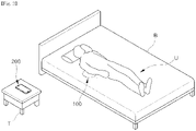
- a sleep management system 1 may include a sleep data acquisition apparatus 100 configured to obtain sleep-related data SD (hereinafter referred to as sleep data) of a user, and a user terminal 200 configured to obtain sleep-related information (hereinafter referred to as sleep information) of the user on the basis of the sleep data SD.
- the sleep information may include sleep time information related to a sleep time of a user U, and sleep summary information to be displayed to the user U.
- the sleep data acquisition apparatus 100 may collect the sleep data SD of the user while the user is sleeping, falling asleep, or waking up. Also, the sleep data acquisition apparatus 100 may transmit the sleep data SD of the user to the user terminal 200.
- the sleep data acquisition apparatus 100 may detect a heart rate, respiration rate, and movement of the user and generate sleep data SD corresponding to the user's heart rate, respiration rate, and movement.
- the sleep data acquisition apparatus 100 may detect a vibration caused by the user's heart rate, respiration rate, and movement and generate sleep data SD corresponding to the detected vibration.
- the sleep data acquisition apparatus 100 may transmit pieces of sleep data SD generated every predetermined time interval to the user terminal 200 in a wireless manner.
- the user terminal 200 may receive the sleep data SD of the user from the sleep data acquisition apparatus 100, and may obtain a sleep state SS of the user or sleep information SI of the user on the basis of the received sleep data SD.
- the user terminal 200 may obtain the sleep state SS of the user U.
- the user terminal 200 may determine whether the user U is lying on a bed B, whether the user U is sleeping, in which sleep stage the user U is, whether the user U wakes up briefly while sleeping, whether the user U is falling asleep again, whether the user U completely wakes up, whether the user U gets out of the bed B, and the like.
- the user terminal 200 may obtain sleep time information such as a time at which the user U lies on the bed B, a time at which the user U falls asleep, a time at which the sleep stage of the user U changes, a time at which the user U wakes up briefly while sleeping, a time at which the user U falls asleep again, a time at which the user U wakes up, and a time at which the user U gets out of the bed B on the basis of the sleep state SS of the user U.
- sleep time information such as a time at which the user U lies on the bed B, a time at which the user U falls asleep, a time at which the sleep stage of the user U changes, a time at which the user U wakes up briefly while sleeping, a time at which the user U falls asleep again, a time at which the user U wakes up, and a time at which the user U gets out of the bed B on the basis of the sleep state SS of the user U.
- the user terminal 200 may process the sleep time information of the user U, generate sleep summary information, and display the sleep summary information to the user U. For example, the user terminal 200 may display a total sleep time, a time it takes the user to fall asleep, the number of times the user wakes up while sleeping, sleep efficiency, a deep sleep time, a rapid eye movement (REM) sleep time, or the like of the user on the basis of the sleep data SD of the user.
- REM rapid eye movement
- the configuration of the sleep management system 1 is not limited to that shown in FIG. 1 .
- the sleep management system 1 may further include a sleep management server SV in addition to the sleep data acquisition apparatus 100 and the user terminal 200.
- the sleep management server SV may receive the sleep data SD from the user terminal 200, process the received sleep data SD, and generate the sleep state SS or the sleep information SI of the user U. Also, the sleep management server SV may transmit the sleep state SS or the sleep information SI of the user U to the user terminal 200.
- the user terminal 200 may transmit the obtained sleep data SD to the sleep management server SV over a wide area network (WAN) and receive the sleep state SS or the sleep information SI of the user U from the sleep management server SV. Also, when the sleep state SS of the user U is received from the sleep management server SV, the user terminal 200 may generate the sleep information SI of the user U on the basis of the sleep state SS of the user U.
- WAN wide area network
- the sleep management server SV may obtain sleep data of a plurality of users from a plurality of user terminals, process the sleep data, and generate sleep information of the plurality of users. In this case, the sleep management server SV may manage the sleep information of the plurality of users on a user basis.
- the sleep management server SV may manage the sleep information SI of the plurality of users on a group basis, wherein the groups are set by the users. For example, when the plurality of users are set as family members, the sleep management server SV may transmit sleep information of the family members (the plurality of users) to user terminals of the family members so that the family members can share the sleep information.
- FIG. 3 shows an example of operation of a sleep management system according to an embodiment
- FIG. 4 shows an example of a user's sleep cycle shown in FIG. 3 .
- the sleep data acquisition apparatus 100 may be placed near a user U who is lying on a bed B.
- the sleep data acquisition apparatus 100 may be placed under the bed B of the user U.
- the placement of the sleep data acquisition apparatus 100 is not limited to that shown in FIG. 3 , and the sleep data acquisition apparatus 100 may be placed wherever a heart rate, respiration rate, and movement of the user U can be detected.
- the user terminal 200 may be placed near the sleep data acquisition apparatus 100.
- the user terminal 200 may be placed on a table T provided near the bed B of the user U.
- the placement of the user terminal 200 is not limited to that shown in FIG. 3 , and the user terminal 200 may be placed wherever the sleep data SD can be received from the sleep data acquisition apparatus 100.
- the sleep data acquisition apparatus 100 may detect a heart rate, respiration rate, and movement of the user U who is lying on the bed B and transmit sleep data SD corresponding to the user U's heart rate, respiration rate, and movement to the user terminal 200. Also, the user terminal 200 may determine a time at which the user U lies on the bed B on the basis of the sleep data SD or by using the sleep management server SV.
- the sleep data acquisition apparatus 100 can detect an amount of vibration less than a reference value, which is caused in daily life of the user U, before the user U lies on the bed B. However, the sleep data acquisition apparatus 100 may interpret the amount of vibration less than the reference value as meaningless noise and not transmit data corresponding to the amount of vibration less than the reference value to the user terminal 100. As a result, the user terminal 200 may not receive sleep data from the sleep data acquisition apparatus 100 before the user U lies on the bed B.
- the user terminal 200 may detect an amount of vibration greater than or equal to the reference value when the user U lies on the bed B.
- the sleep data acquisition apparatus 100 may transmit sleep data corresponding to the amount of vibration greater than or equal to the reference value to the user terminal 200.
- the user terminal 200 or the sleep management server SV may determine that the user U is lying on the bed B and determine a start time of the reception of the sleep data as a time at which the user U lies on the bed B.
- the sleep data acquisition apparatus 100 may detect a heart rate, respiration rate, and movement of the user U who is sleeping and transmit sleep data SD corresponding to the user U's heart rate, respiration rate, and movement to the user terminal 200. Also, the user terminal 200 may determine a time at which the user U falls asleep on the basis of the sleep data SD or by using the sleep management server SV.
- the user U may not fall asleep as soon as the user U lies on the bed B and may not fall asleep for a short period of several minutes or for several hours. Accordingly, the time at which the user U lies on the bed B may be different from the time at which the user falls asleep.
- the user U has a different heart rate, respiration rate, and movement when he or she is awake than when he or she is asleep.
- respiration rate a different heart rate
- respiration rate a different respiratory rate
- movement when he or she is awake than when he or she is asleep.
- respiration rate a decreased heart rate and respiration rate while sleeping.
- the user terminal 200 or the sleep management server SV may determine whether the user U is awake or asleep on the basis of the user U's heart rate, respiration rate, and movement and determine the time at which the user falls asleep on the basis of a result of the determination of whether the user U is awake or asleep.
- the sleep data acquisition apparatus 100 may detect the user U's heart rate, respiration rate, and movement every predetermined time interval and transmit sleep data SD corresponding to the user U's heart rate, respiration rate, and movement to the user terminal 200.
- the user terminal 200 or the sleep management server SV may determine a sleep stage of the user U and determine whether the user U consciously or unconsciously wakes up.
- human sleep It is well known that a person does not suddenly fall asleep, maintain deep sleep, and then suddenly wake up, but that human sleep includes certain stages and cycles. For example, as shown in FIG. 4 , human sleep gradually proceeds to a deep sleep stage after falling sleep. Subsequently, human sleep repeatedly alternates between a light sleep stage and the deep sleep stage.
- human sleep may be largely divided into REM sleep and non-REM sleep, and REM sleep may be divided into a total of four stages.
- REM sleep makes up about 20% to 25% of the entire sleep, and during REM sleep, a characteristic electroencephalogram (EEG) exists, muscle tension is reduced to the lowest level and characteristic REM is observed.
- EEG electroencephalogram
- non-REM sleep may be divided into a first stage, a second stage, a third stage, and a fourth stage, as described above.
- Sleep in the third stage and the fourth stage is typically referred to as deep sleep
- sleep in the first stage and the second stage is typically referred to as light sleep.
- the deep sleep makes up about 15 to 20% of the entire sleep.
- a heart rate and a respiration rate during non-REM sleep are decreased further than during waking and are relatively regular.
- human sleep exhibits a characteristic heart rate, respiration rate, and movement in each of the stages.
- the user terminal 200 or the sleep management server SV may determine a sleep stage of the user U on the basis of the sleep data SD indicating the user U's heart rate, respiration rate, and movement during sleep.
- the user terminal 200 or the sleep management server SV may determine whether the sleep of the user U enters or exits a REM sleep stage, and may determine and/or store a time at which the REM sleep stage is entered and a time at which the REM sleep stage is exited.
- the user terminal 200 or the sleep management server SV may determine whether the sleep of the user U enters or exits deep sleep stages (the third and fourth stages) of non-REM sleep, and may determine and/or store a time at which the deep sleep stage is entered and a time at which the deep sleep stage is exited.
- a sleeping person consciously or unconsciously wakes up. For example, as shown in FIG. 4 , a person enters a waking stage during REM sleep. Also, in the waking stage, a person may consciously or unconsciously wake up, and, while waking, his or her heart rate and respiration rate increase, and his or her movement becomes active.
- the user terminal 200 or the sleep management server SV may determine whether the user U wakes from sleep on the basis of the sleep data SD indicating the user U's heart rate, respiration rate, and movement during sleep.
- the user terminal 200 or the sleep management server SV may determine whether the user U wakes from the sleep, and may determine and/or store a time at which the user U wakes up. Also, when the user U falls asleep again within a reference time (e.g., 30 minutes) after waking up, the user terminal 200 or the sleep management server SV may determine that the user U continues to sleep, and may determine and/or store a time at which the user U falls asleep again.
- a reference time e.g. 30 minutes
- the user U may wake up and then get out of the bed B.
- the user terminal 200 or the sleep management server SV may determine whether the user U wakes up and whether the user U gets out of the bed B on the basis of the sleep data SD received from the sleep data acquisition apparatus 100. Also, the user terminal 200 or the sleep management server SV may determine and/or store a time at which the user U wakes up and a time at which the user U gets out of the bed B.
- the user terminal 200 or the sleep management server SV may obtain the sleep information SI of the user U on the basis of the sleep data SD.
- the user terminal 200 or the sleep management server SV may obtain sleep time information such as a time at which the user U lies on the bed B, a time at which the user U falls asleep, a time at which the sleep stage of the user U changes, a time at which the user U wakes up briefly while sleeping, a time at which the user U falls asleep again, a time at which the user U wakes up, and a time at which the user U gets out of the bed B.
- the user terminal 200 or the sleep management server SV may generate sleep summary information of the user U on the basis of the sleep time information of the user U.
- the user terminal 200 or the sleep management server SV may obtain sleep summary information such as a total sleep time, a time it takes the user to fall asleep, the number of times the user wakes up while sleeping, sleep efficiency, a deep sleep time, and a REM sleep time on the basis of the sleep time information of the user U.
- the user terminal 200 may display the sleep summary information to the user according to input of the user.
- FIG. 5 shows a configuration of a sleep data acquisition apparatus included in a sleep management system according to an embodiment.
- the sleep data acquisition apparatus 100 may include a sleep sensor 120, a sensor communicator 130, and a sensor controller 110.
- the sleep sensor 120 may detect a heart rate, a respiration rate, and a movement of a user who is lying on a bed and output an electrical signal corresponding to the detected heart rate, respiration rate, and movement of the user to the sensor controller 110.
- the sleep sensor 120 may include a piezoelectric sensor 121 configured to detect pressure caused by the heart rate, respiration rate, and movement of the user and output an electrical signal corresponding to the detected pressure.
- the piezoelectric sensor 121 uses a piezoelectric effect in which electric polarization occurs on a surface of a crystal when a force is applied to the crystal.
- the piezoelectric sensor 121 generates an alternating current (AC) voltage when pressure is applied thereto, and generates a vibration when the AC voltage is applied thereto.
- AC alternating current
- the piezoelectric sensor 121 may output an electrical signal corresponding to the pressure applied thereto.
- the sleep sensor 120 may include an acceleration sensor 123 configured to detect a vibration caused by the heart rate, respiration rate, and movement of the user and output an electrical signal corresponding to the detected vibration.
- the acceleration sensor 123 is a sensor configured to measure a change in speed per unit time. When the acceleration sensor 123 is moved or vibrated by the heart rate, respiration rate, and movement of the user, the acceleration sensor 123 may output an electrical signal corresponding to the movement or vibration.
- the sleep sensor 120 does not have to include both of the piezoelectric sensor 121 and the acceleration sensor 123. Depending on a designer's selection, the sleep sensor 120 may include either the piezoelectric sensor 121 or the acceleration sensor 123.
- the sensor communicator 130 may include a short-range communication module 131 configured to transmit and/or receive data to and/or from the user terminal 200.
- the short-range communication module 131 may communicate with a communication partner through various communication schemes.
- the short-range communication module 131 may communicate with a communication partner through a WiFi communication scheme (IEEE 802.11), a Bluetooth communication scheme (IEEE 802.15.1), a Zigbee communication scheme (IEEE 802.15.4), or the like.
- the short-range communication module 131 does not employ all of the WiFi communication scheme, the Bluetooth communication scheme, and the Zigbee communication scheme, and may employ at least one of the WiFi communication scheme, the Bluetooth communication scheme, and the Zigbee communication scheme.
- the sensor controller 110 may include a memory 113 configured to store and/or recall programs and data, and a processor 111 configured to process the data according to the programs stored in the memory 113 and control the sleep sensor 120 and the sensor communicator 130.
- the memory 113 may store a control program and control data for controlling operation of the sleep data acquisition apparatus 100, or may recall sleep data SD obtained through the sleep sensor 120.
- the memory 113 may include a volatile memory such as a static random access memory (S-RAM) and a dynamic RAM (D-RAM) and a non-volatile memory such as a read-only memory (ROM), an erasable programmable ROM (EPROM), an electrically erasable programmable ROM (EEPROM), and a flash memory.
- a volatile memory such as a static random access memory (S-RAM) and a dynamic RAM (D-RAM)
- a non-volatile memory such as a read-only memory (ROM), an erasable programmable ROM (EPROM), an electrically erasable programmable ROM (EEPROM), and a flash memory.
- the volatile memory which is a memory that loses data recalled therein when power is cut off, may temporarily recall programs and data.
- the volatile memory may recall a control program and control data or recall the sleep data SD obtained by the sleep sensor 120.
- the non-volatile memory which is a memory that maintains data stored therein even though power is cut off, may semi-permanently store programs and data.
- the non-volatile memory may store a control program and control data for controlling operation of the sleep data acquisition apparatus 100.
- the processor 111 may process the sleep data SD input from the sleep sensor 120 according to the control program and control data stored in the memory 113 and transmit the sleep data to the user terminal 200 through the sensor communicator 130.
- the processor 111 may obtain an electrical signal output by the sleep sensor 120 every predetermined time interval and generate the sleep data SD by digitalizing the obtained electrical signal. Also, the processor 111 may output the sleep data SD and a control signal to the sensor communicator 130 so that the sensor communicator 130 can transmit the sleep data SD to the user terminal 200.
- the sensor controller 110 may control operation of the sleep sensor 120 and the sensor communicator 130 included in the sleep data acquisition apparatus 100.
- An operation of the sleep data acquisition apparatus 100 which will be described below, may be interpreted as being controlled by the sensor controller 110.
- FIG. 6 shows a configuration of a user terminal included in a sleep management system according to an embodiment.
- the user terminal 200 may include a user input/output unit 220, a terminal communicator 230, a terminal storage 240, and a terminal controller 210.
- the user input/output unit 220 may receive a user input from a user and output information corresponding to the user input.
- the user input/output unit 220 may include a touch screen module 221 configured to receive a touch input from a user and display information corresponding to the received touch input, a button module 223 configured to receive a predetermined user input from the user, a microphone 225 configured to receive a voice input from the user, and a speaker 227 configured to output sounds.
- a touch screen module 221 configured to receive a touch input from a user and display information corresponding to the received touch input
- a button module 223 configured to receive a predetermined user input from the user
- a microphone 225 configured to receive a voice input from the user
- a speaker 227 configured to output sounds.
- the touch screen module 221 may receive a touch input from a user and display image information corresponding to the received touch input.
- the touch screen module 221 may receive at least one touch or a continuous touch movement through the user's body (e.g., his or her finger) or a touchable input means (e.g., a stylus pen).
- a touchable input means e.g., a stylus pen
- the touch screen module 221 may convert the touch input of the user into a digital signal corresponding to the touch input (e.g., an x coordinate and a y coordinate) and output the digital signal to the terminal controller 210.
- a digital signal corresponding to the touch input e.g., an x coordinate and a y coordinate
- the touch screen module 221 may be implemented as a resistive-type module, a capacitive-type module, an infrared-type module, or an acoustic-wave-type module.
- the button module 223 may be provided on a front surface, a side surface, or a rear surface of a housing of the user terminal 200, and may include a plurality of buttons capable of receiving a predetermined user input.
- the button module 223 may include at least one of a power/lock button, a volume button, a menu button, a home button, and a return button.
- the terminal communicator 230 may transmit and/or receive data to and/or from the sleep data acquisition apparatus 100 and the sleep management server SV, which have been described above. In addition, the terminal communicator 230 may transmit and/or receive data to and/or from other user terminals.
- the terminal communicator 230 may include a short-range communication module 231 configured to transmit and/or receive data to and/or from a communication partner at a location that is relatively near the communication partner, and a mobile communication module 233 configured to transmit and/or receive data to and/or from a communication partner regardless of a distance from the communication partner.
- a short-range communication module 231 configured to transmit and/or receive data to and/or from a communication partner at a location that is relatively near the communication partner
- a mobile communication module 233 configured to transmit and/or receive data to and/or from a communication partner regardless of a distance from the communication partner.
- the short-range communication module 231 may communicate with a communication partner through various communication schemes.
- the short-range communication module 231 may communicate with a communication partner through a WiFi communication scheme (IEEE 802.11), a Bluetooth communication scheme (IEEE 802.15.1), a Zigbee communication scheme (IEEE 802.15.4), or the like
- the short-range communication module 231 does not employ all of the WiFi communication scheme, the Bluetooth communication scheme, and the Zigbee communication scheme, and may employ at least one of the WiFi communication scheme, the Bluetooth communication scheme, and the Zigbee communication scheme.
- the mobile communication module 233 may communicate with a communication partner through various communication schemes.
- the mobile communication module 233 may communicate with the communication partner by using a second generation communication scheme such as time division multiple access (TDMA) and code division multiple access (CDMA), a third generation communication scheme such as wideband code division multiple access (WCDMA), code division multiple access 2000 (CDMA2000), wireless broadband (Wibro), and world interoperability for microwave access (WiMAX), a fourth generation communication scheme such as long term evolution (LTE) and wireless broadband evolution, or the like.
- TDMA time division multiple access
- CDMA code division multiple access
- WCDMA wideband code division multiple access
- CDMA2000 code division multiple access 2000
- Wibro wireless broadband
- WiMAX world interoperability for microwave access
- LTE long term evolution
- LTE long term evolution
- Various application programs and data for performing various functions may be stored in the terminal storage 240 according to a user input received through the user input/output unit 220.
- an operating system (OS) program for managing configurations and resources (software and hardware) included in the user terminal 200
- a video playback program for playing a video and displaying a picture
- a word processor program for creating and editing a document
- a browser for accessing a WAN such as the Internet, and the like
- a browser for accessing a WAN such as the Internet, and the like
- the terminal storage 240 may include a non-volatile memory in which no program or data is lost even when power is cut off.
- the terminal storage 240 may include a flash memory for easily writing and erasing data or the like.
- the terminal controller 210 may include a memory 213 configured to store and/or recall programs and data, and a processor 211 configured to process data according to the program stored in the memory 213 and control the user input/output unit 220, the terminal communicator 230, and the terminal storage 240.
- the memory 213 may store a control program and control data for controlling operation of the user terminal 200, or may recall a user input received through the user input/output unit 220, communication data received through the terminal communicator 230, an application program loaded from the terminal storage 240, and the like.
- the memory 213 may include a volatile memory such as an S-RAM and a D-RAM and a non-volatile memory such as a ROM, an EPROM, an EEPROM, and a flash memory.
- a volatile memory such as an S-RAM and a D-RAM
- a non-volatile memory such as a ROM, an EPROM, an EEPROM, and a flash memory.
- the volatile memory which is a memory that loses data stored therein when power is cut off, may temporarily store programs and data.
- the volatile memory may recall an application program or may recall the sleep data SD received from the sleep data acquisition apparatus 100.
- the non-volatile memory which is a memory capable of maintaining data stored therein even though power is cut off, may semi-permanently store programs and data.
- the non-volatile memory may store a booting program and data for booting the user terminal 200 and the sleep data SD received from the sleep data acquisition apparatus 100.
- the processor 211 may process data according to a program recalled in the memory 213 and control the user input/output unit 220, the terminal communicator 230, and the terminal storage 240 according to the processed data.
- the processor 211 may process the sleep data SD received through the terminal communicator 230 to generate sleep time information of the user. Also, the processor 211 may process the sleep time information of the user to generate sleep summary information of the user. Also, the processor 211 may output the sleep summary information of the user and a control signal to the user input/output unit 220 so that the sleep summary information can be displayed through the touch screen module 221.
- the processor 211 may output the sleep data SD and a control signal to the terminal communicator 230 so that the sleep data SD can be transmitted to the sleep management server SV. Also, when the sleep information SI is received from the sleep management server SV, the processor 211 may obtain the sleep summary information from the sleep information SI. Also, the processor 211 may output the sleep summary information and a control signal to the user input/output unit 220 so that the sleep summary information can be displayed through the touch screen module 221.
- the terminal controller 210 may control operation of the user input/output unit 220, the terminal communicator 230, and the terminal storage 240 included in the user terminal 200.
- An operation of the user terminal 200 which will be described below, may be interpreted as being controlled by the terminal controller 210.
- control operation of the terminal controller 210 may be implemented as a sleep management application program.
- the user may download an application program through a WAN or a local area network (LAN).
- LAN local area network
- the terminal controller 210 may execute a control operation that will be described below.
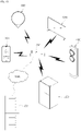
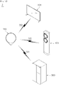
- FIG. 7 shows an example of communication between a sleep management system and home appliances according to an embodiment
- FIG. 8 shows another example of communication between a sleep management system and home appliances according to an embodiment.
- the sleep data acquisition apparatus 100 may transmit sleep data SD obtained from a user to the user terminal 200 in a non-contact manner.
- the user terminal 200 may process the sleep data SD to determine a sleep state SS.
- the user terminal 200 may transmit controls signals CS1, CS2, and CS3 for controlling home appliances 300, 400, and 500 to the home appliances 300, 400, and 500 on the basis of the sleep state SS.
- the user terminal 200 may transmit a control signal for decreasing a volume of a sound output by an image display apparatus 300 or stopping operation of the image display apparatus 300 to the image display apparatus 300. Also, the user terminal 200 may transmit a control signal for changing an operation mode of an air conditioner 400 or changing a target temperature of the air conditioner 400 to the air conditioner 400. Also, the user terminal 200 may transmit a control signal for delaying operation of a refrigerator 500 to the refrigerator 500.
- the sleep data acquisition apparatus 100 and the user terminal 200 may communicate with each other on a one-to-one basis, and the user terminal 200 and the home appliances 300, 400, and 500 may communicate with each other on a one-to-one basis.
- the sleep data acquisition apparatus 100, the user terminal 200, and the home appliances 300, 400, and 500 may form a LAN through an access point AP.
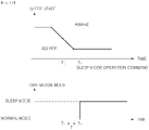
- FIG. 9 shows an example of interoperation between a sleep management system and an image display apparatus according to an embodiment
- FIG. 10 shows operation of an image display apparatus during the interoperation shown in FIG. 9 .
- the user terminal 200 receives the sleep data SD from the sleep data acquisition apparatus 100 (1005).
- the sleep data acquisition apparatus 100 may detect a user's heart rate, respiration rate, and movement every predetermined time interval and transmit sleep data SD corresponding to the user's heart rate, respiration rate, and movement to the user terminal 200.
- the sleep data acquisition apparatus 100 may transmit the sleep data SD to the user terminal 200 whenever the user's heart rate, respiration rate, and movement are detected or whenever a request for the sleep data SD is received from the user terminal 200 in addition to every predetermined time interval.
- the user terminal 200 obtains a sleep state SS of the user on the basis of the sleep data SD (1010).
- the user terminal 200 may directly determine the sleep state SS of the user on the basis of the sleep data SD or may receive the sleep state SS through the sleep management server SV.
- the user terminal 200 may obtain the user's heart rate, respiration rate, and movement from the sleep data SD and determine whether the user lies on a bed, whether the user falls asleep, in which sleep stage the user is, whether the user wakes up briefly while sleeping, whether the user falls asleep again, whether the user completely wakes up, whether the user gets out of bed, and the like on the basis of the obtained heart rate, respiration rate, and movement.
- the user terminal 200 may transmit the sleep data SD to the sleep management server SV and may receive the sleep state SS, such as whether the user lies on a bed, whether the user falls asleep, in which sleep stage the user is, whether the user wakes up briefly while sleeping, whether the user falls asleep again, whether the user completely wakes up, and whether the user gets out of bed, from the sleep management server SV.
- the sleep state SS such as whether the user lies on a bed, whether the user falls asleep, in which sleep stage the user is, whether the user wakes up briefly while sleeping, whether the user falls asleep again, whether the user completely wakes up, and whether the user gets out of bed, from the sleep management server SV.
- the user terminal 200 determines whether the user falls asleep on the basis of the sleep state SS of the user (1020).
- the user terminal 200 may obtain the sleep state SS of the user. In this case, the user terminal 200 may determine whether the sleep state SS of the user is changed from an awake state to an asleep state.
- the user terminal 200 When the user is not asleep (no in 1020), the user terminal 200 repeatedly receives the sleep data SD and determines the sleep state of the user.
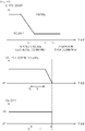
- the user terminal 200 determines whether a first time T1 passes (1030).
- the user terminal 200 may determine whether the first time T1 passes after the user is detected as falling asleep (T0).
- the user terminal 200 waits for the first time T1 to pass.
- Sleep of the user may be disturbed by an external stimulus immediately after the user falls asleep. For example, when a volume of a sound output by the image display apparatus 300 changes immediately after the user falls asleep, the user may not fall asleep but may wake up due to the change in the sound volume.
- the user terminal 200 may wait for the first time T1 after the user is detected as falling asleep (T0).
- the user terminal 200 transmits a sound volume decrease command to the image display apparatus 300 (1035).
- the user terminal 200 may transmit the sound volume decrease command to the image display apparatus 300 to decrease the volume of the sound output by the image display apparatus 300.
- the image display apparatus 300 decreases the volume of the output sound (1037).
- the image display apparatus 300 may decrease the volume of the output sound to a predetermined volume level (a value of "0" or higher) at once or step by step.
- the user terminal 200 may transmit the sound volume decrease command to the image display apparatus 300, and the image display apparatus 300 may decrease the volume of the output sound.
- the image display apparatus 300 may decrease a brightness of an image output by the image display apparatus 300 in addition to decreasing the volume of the output sound.
- the user terminal 200 determines whether a second time T2 passes (1040).
- the user terminal 200 may determine whether the second time T2 passes after the user is detected as falling asleep (T0).
- the user terminal 200 waits for the second time T2 to pass.
- the sleep of the user may be disturbed by an external stimulus immediately after the user falls asleep. For example, when the image display apparatus 300 is turned off immediately after the user falls asleep, the user may not fall asleep but may be woken up by the image display apparatus 300 being turned off.
- the user terminal 200 may wait for the second time T2 after the user is detected as falling asleep (T0).
- the user terminal 200 transmits an operation stop command to the image display apparatus 300 (1045).
- the user terminal 200 may transmit the operation stop command to the image display apparatus 300 to turn off the image display apparatus 300.
- the image display apparatus 300 stops operating (1047). That is, the image display apparatus 300 is turned off.
- the user terminal 200 may transmit the operation stop command to the image display apparatus 300, and the image display apparatus 300 may be turned off.
- FIG. 11 shows another example of interoperation between a sleep management system and an image display apparatus according to an embodiment
- FIG. 12 shows operation of an image display apparatus during the interoperation shown in FIG. 11 .
- the user terminal 200 receives the sleep data SD from the sleep data acquisition apparatus 100 (1105).
- the sleep data acquisition apparatus 100 may detect a user's heart rate, respiration rate, and movement every predetermined time interval and transmit sleep data SD corresponding to the user's heart rate, respiration rate, and movement to the user terminal 200.
- the user terminal 200 obtains a sleep state SS of the user on the basis of the sleep data SD (1110).
- the user terminal 200 may directly determine the sleep state SS of the user on the basis of the sleep data SD, or may receive the sleep state SS through the sleep management server SV.
- the user terminal 200 may obtain a sleep state, such as whether the user lies on a bed, whether the user falls asleep, in which sleep stage the user is, whether the user wakes up briefly while sleeping, whether the user falls asleep again, whether the user completely wakes up, and whether the user gets out of bed, on the basis of the sleep data SD.
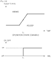
- the user terminal 200 determines whether the user wakes on the basis of the sleep state SS of the user (1120).
- the user terminal 200 may obtain the sleep state SS of the user on the basis of the sleep data SD of the user. In this case, the user terminal 200 may determine whether the sleep state SS of the user is changed from the asleep state to the awake state.
- the user terminal 200 may determine whether the user wakes on the basis of a wake-up time preset by the user in conjunction with the sleep state SS of the user.
- the user terminal 200 may determine that the user is awake.
- the user terminal 200 determines whether the sleep state SS of the user is maintained as the awake state for a predetermined reference time or longer. When the sleep state SS of the user is maintained as the awake state for the predetermined reference time or longer, the user terminal 200 may determine that the user is awake. This is to provide a sufficient sleep time to the user before the wake-up time preset by the user.
- the user terminal 200 When the user is not awake (no in 1120), the user terminal 200 repeatedly receives the sleep data SD and determines the sleep state of the user.
- the user terminal 200 When the user is awake (yes in 1120), the user terminal 200 transmits an operation start command to the image display apparatus 300 (1125).
- the user terminal 200 may transmit the operation start command to the image display apparatus 300 to turn on the image display apparatus 300.
- the image display apparatus 300 starts to operate (1127). That is, the image display apparatus 300 is turned on.
- the user terminal 200 transmits the operation start command to the image display apparatus 300 and turns on the image display apparatus 300.
- the user terminal 200 may determine the sleep state of the user or receive the sleep state of the user, and may control operation of the image display apparatus 300 according to the sleep state of the user.
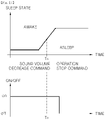
- FIG. 13 shows an example of interoperation between a sleep management system and an air conditioner according to an embodiment
- FIG. 14 shows an example of operation of the air conditioner during the interoperation shown in FIG. 13
- FIG. 15 shows an example of operation of the air conditioner in a sleep mode.
- the user terminal 200 receives the sleep data SD from the sleep data acquisition apparatus 100 (1205).
- the sleep data acquisition apparatus 100 may detect a user's heart rate, respiration rate, and movement every predetermined time interval and transmit sleep data SD corresponding to the user's heart rate, respiration rate, and movement to the user terminal 200.
- the user terminal 200 obtains a sleep state SS of the user on the basis of the sleep data SD (1210).
- the user terminal 200 may directly determine the sleep state SS of the user on the basis of the sleep data SD, or may receive the sleep state SS through the sleep management server SV.
- the user terminal 200 may obtain a sleep state, such as whether the user lies on a bed, whether the user falls asleep, in which sleep stage the user is, whether the user wakes up briefly while sleeping, whether the user falls asleep again, whether the user completely wakes up, and whether the user gets out of bed, on the basis of the sleep data SD.
- the user terminal 200 determines whether the user falls asleep on the basis of the sleep state SS of the user (1220).
- the user terminal 200 may obtain the sleep state SS of the user on the basis of the sleep data SD of the user. In this case, the user terminal 200 may determine whether the sleep state SS of the user is changed from the awake state to the asleep state.
- the user terminal 200 When the user is not asleep (no in 1220), the user terminal 200 repeatedly receives the sleep data SD and determines the sleep state of the user.
- the user terminal 200 determines whether a first time T1 passes (1230).
- the user terminal 200 waits for the first time T1 to pass.
- Sleep of the user may be disturbed by an external stimulus immediately after the user falls asleep.
- the air conditioner 400 operates immediately after the user falls asleep, the user may not fall asleep but may wake due to the sudden operation of the air conditioner 400.
- the user terminal 200 may wait for the first time T1 after the user is detected as falling asleep (T0).
- the user terminal 200 transmits a sleep mode operation command to the air conditioner 400 (1235).
- the user terminal 200 may control the air conditioner 400.
- the user terminal 200 may control the air conditioner 400 so that the air conditioner 400 operates in a predetermined sleep mode.
- the sleep mode of the air conditioner 400 will be described in detail below.
- the air conditioner 400 operates in the sleep mode (1237).
- the user terminal 200 may transmit the sleep mode operation command to the air conditioner 400, and the air conditioner 400 may operate in the sleep mode.
- the sleep mode is an operation mode of the air conditioner 400 in which an indoor temperature is properly adjusted while the user sleeps.
- a target temperature of the air conditioner 400 may change according to a predetermined profile in the sleep mode, and the sleep mode may be divided into a plurality of stages according to a profile of the target temperature.
- the sleep mode may include a sleep induction stage in which sleep of the user is induced, a sleep maintenance step in which the sleep of the user is maintained, and a wake-up inducing stage in which waking of the user is induced.
- the air conditioner 400 may quickly lower the indoor temperature to a predetermined sleep induction temperature in the sleep induction stage.
- the air conditioner 400 may slowly increase the indoor temperature and maintain the indoor temperature at a predetermined sleep maintenance temperature when the indoor temperature reaches the sleep maintenance temperature. Also, in order to prevent the user from waking up briefly during sleep in the sleep maintenance stage, the air conditioner 400 may temporarily lower the indoor temperature.
- the air conditioner 400 may increase the indoor temperature to a sleep stop temperature to induce waking of the user.
- the sleep induction temperature, the sleep maintenance temperature, and the sleep stop temperature may be set by the user through the user terminal 200.
- the air conditioner 400 may properly adjust the indoor temperature at the wake-up time preset by the user for comfortable sleep of the user.
- the wake-up time may be set through the user terminal 200, and when the user falls asleep, the user terminal 200 may transmit the wake-up time preset by the user to the air conditioner 400 together with the sleep mode operation command.
- FIG. 16 shows another example of interoperation between a sleep management system and an air conditioner according to an embodiment
- FIG. 17 shows operation of the air conditioner during the interoperation shown in FIG. 16 .
- the user terminal 200 receives the sleep data SD from the sleep data acquisition apparatus 100 (1305).
- the sleep data acquisition apparatus 100 may detect a user's heart rate, respiration rate, and movement every predetermined time interval and transmit sleep data SD corresponding to the user's heart rate, respiration rate, and movement to the user terminal 200.
- the user terminal 200 obtains a sleep state SS of the user on the basis of the sleep data SD (1310).
- the user terminal 200 may directly determine the sleep state SS of the user on the basis of the sleep data SD, or may receive the sleep state SS through the sleep management server SV.
- the user terminal 200 may obtain a sleep state, such as whether the user lies on a bed, whether the user falls asleep, in which sleep stage the user is, whether the user wakes up briefly while sleeping, whether the user falls asleep again, whether the user completely wakes up, and whether the user gets out of bed, on the basis of the sleep data SD.
- the user terminal 200 determines whether the user wakes on the basis of the sleep state SS of the user (1320).
- the user terminal 200 may determine whether the user wakes on the basis of a wake-up time preset by the user in conjunction with the sleep state SS of the user.
- the user terminal 200 may determine that the user is awake.
- the user terminal 200 determines whether the sleep state SS of the user is maintained as the awake state for a predetermined reference time or longer. When the sleep state SS of the user is maintained as the awake state for the predetermined reference time or longer, the user terminal 200 determines that the user is awake. This is to provide a sufficient sleep time to the user before the wake-up time preset by the user.
- the user terminal 200 When the user is not awake (no in 1320), the user terminal 200 repeatedly receives the sleep data SD and determines the sleep state of the user.
- the user terminal 200 When the user is awake (yes in 1320), the user terminal 200 transmits a normal mode operation command to the air conditioner 400 (1325).
- the user terminal 200 may transmit the normal mode operation command to the air conditioner 400 so that the operation mode of the air conditioner 400 is changed to the normal mode.
- the air conditioner 400 changes the operation mode from the sleep mode to the normal mode (1327).
- the user terminal 200 transmits the normal mode operation command to the air conditioner 400, and the air conditioner 400 operates in the normal mode.
- the user terminal 200 determines whether the user gets out of bed (1330).
- the user terminal 200 may receive the sleep data SD from the sleep data acquisition apparatus 100 and obtain the sleep state SS of the user on the basis of the received sleep data SD.
- the user terminal 200 may determine whether the user gets out of bed on the basis of the sleep state SS of the user.
- the user terminal 200 transmits an operation stop command to the air conditioner 400 (1335).
- the user terminal 200 may determine that the user no longer wants to continue sleeping, and thus may stop the operation of the air conditioner 400. Accordingly, the user terminal 200 may transmit the operation stop command to the air conditioner 400 to turn off the air conditioner 400.
- the air conditioner 400 stops operating (1337). That is, the air conditioner 400 is turned off.
- the user terminal 200 transmits the operation stop command to the air conditioner 400, and the air conditioner 400 is turned off.
- the user terminal 200 may determine the sleep state of the user or receive the sleep state of the user, and may control operation of the air conditioner 400 according to the sleep state of the user.
- the user terminal 200 may display the sleep information SI (more particularly, sleep summary information) of the user according to a user input, and may preset operation of the home appliances 300, 400, and 500 to be performed during sleep.
- SI more particularly, sleep summary information
- the user terminal 200 may display a graphic user interface for displaying the sleep information SI of the user and presetting the operation of the home appliances 300, 400, and 500.
- the graphic user interface displayed on the user terminal 200 will be described below.
- FIG. 18 shows an example of a sleep information display screen displayed on a user terminal according to an embodiment.
- a sleep information display screen 2001 shown in FIG. 18 may be displayed on the user terminal 200 according to a user input.
- a plurality of menus 2100, 2200, 2300, and 2400 for selecting information displayed on the user terminal 200 may be displayed at one side of the sleep information display screen 2001.
- the plurality of menus 2100, 2200, 2300, and 2400 include a sleep summary menu 2100 for displaying sleep summary information, a daily sleep summary menu 2200 for displaying sleep summary information associated with the current date, a monthly sleep summary menu 2300 for displaying sleep summary information associated with a month of the current date, and a home appliance menu 2400 for setting operation of a home appliance.
- a sleep summary menu 2100 for displaying sleep summary information
- a daily sleep summary menu 2200 for displaying sleep summary information associated with the current date
- a monthly sleep summary menu 2300 for displaying sleep summary information associated with a month of the current date
- a home appliance menu 2400 for setting operation of a home appliance.
- the sleep summary information 2120 may be displayed at the one side of the sleep information display screen 2001.
- the sleep summary information 2120 is generated by processing some of the sleep information so that the user can check his or her sleep quality.
- the sleep summary information 2120 may include a total sleep time, a time it takes the user to fall asleep, the number of times the user wakes-up while sleeping, sleep efficiency, a deep sleep time, an REM sleep time, or the like of the user.
- a sleep score 2110 may be displayed at the one side of the sleep information display screen 2001.
- the sleep score 2110 represents the sleep summary information 2120 in numerical form.
- the user terminal 200 may represent items included in the sleep summary information 2120 in numerical form as numbers, weight the numbers, and then sum the weighted numbers.
- the user may quantitatively confirm his or her sleep quality through the sleep score 2110.
- an alarm time setting menu 2500 for setting a wake-up time and a sleep environment setting menu 2600 for generally setting a sleep environment may be displayed at the one side of the sleep information display screen 2001.
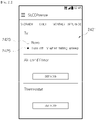
- FIG. 19 shows an example of a home appliance setting screen displayed on a user terminal according to an embodiment.
- FIG. 20 shows an example of an air conditioner setting screen displayed on a user terminal according to an embodiment
- FIG. 21 shows an example of an image display apparatus setting screen display on a user terminal according to an embodiment.
- the user terminal 200 may display a home appliance setting screen 2401 shown in FIG. 19 .
- An air conditioner setting menu 2410 for setting operation of an air conditioner, an image display apparatus setting menu 2420 for setting operation of an image display apparatus, and a thermostat setting menu 2430 for setting operation of a thermostat may be displayed at one side of the home appliance setting screen 2401.
- the user terminal 200 displays an air conditioner setting screen 2411 shown in FIG. 20 .
- the user sets an indoor temperature and an air volume to be applied during sleep through the air conditioner setting screen 2411.
- the air conditioner setting screen 2411 may include a temperature setting region 2413 for setting an indoor temperature during sleep of the user, an air volume setting region 2415 for setting an air volume during the user's sleep, and a storage command region 2417 for storing the set indoor temperature and the set air volume.
- a target indoor temperature set by the user is displayed in the temperature setting region 2413, and the user terminal 200 may raise or lower the target indoor temperature according to a touch input of the user that is input through the temperature setting region 2413.
- an air volume set by the user is displayed in the air volume setting region 2415, and the user terminal 200 may raise or lower the air volume according to a touch input of the user that is input through the air volume setting region 2415.
- the user terminal 200 may store the indoor temperature and the air volume that are set by the user according to a touch input of the user that is input through the storage command region 2417.
- the indoor temperature and the air volume that are set by the user may be transmitted to the air conditioner in the sleep state SS of the user.
- the user terminal 200 may transmit the indoor temperature and the air volume that are set by the user to the air conditioner, and the air conditioner may operate according to the received indoor temperature and air volume.
- the user terminal 200 may display an image display apparatus setting screen 2421 shown in FIG. 21 .
- the user may set operation of the image display apparatus to be performed during sleep.
- a turn-off setting menu 2423 for turning off the image display apparatus while the user sleeps and a turn-off cancellation menu 2421 for preventing the image display apparatus from being turned off while the user sleeps may be displayed in the image display apparatus setting screen 2411, and the user may select one of the turn-off setting menu 2423 and the turn-off cancellation menu 2421.
- the user terminal 200 may transmit an operation stop command for turning off the image display apparatus to the image display apparatus while the user sleeps.
- the user terminal 200 may not transmit the operation stop command to the image display apparatus even though the user is sleeping.
- the user may individually set operation of a home appliance through a graphic user interface displayed on the user terminal 200.
- the user may collectively set operations of a plurality of home appliances through the graphic user interface displayed on the user terminal 200.
- FIG. 22 shows an example of a sleep environment setting screen displayed on a user terminal according to an embodiment
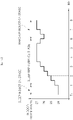
- FIG. 23 shows an example of an indoor temperature setting screen displayed on a user terminal according to an embodiment
- FIG. 24 shows a change in indoor temperature caused by the indoor temperature setting screen shown in FIG. 23 .
- the user terminal 200 may display a sleep environment setting screen 2601 shown in FIG. 22 .
- An image display apparatus setting region 2610 for setting operation of an image display apparatus during sleep of the user, an air conditioner setting region 2620 for setting operation of an air conditioner during the user's sleep, and a thermostat setting region 2630 for setting operation of a thermostat during the user's sleep may be displayed in the sleep environment setting screen 2601.
- a turn-off setting menu 2613 for turning off the image display apparatus while the user sleeps and a turn-off cancellation menu 2611 for preventing the image display apparatus from being turned off while the user sleeps may be displayed in the image display apparatus setting region 2610, and the user may select one of the turn-off setting menu 2613 and the turn-off cancellation menu 2611.
- the user terminal 200 may transmit an operation stop command for turning off the image display apparatus to the image display apparatus while the user sleeps. Also, when the turn-off cancellation menu 2611 is selected, the user terminal 200 may not transmit the operation stop command to the image display apparatus even though the user is sleeping.
- a sleep mode cancellation menu 2621 for canceling sleep mode operation of the air conditioner while the user sleeps may be displayed in the air conditioner setting region 2620. Also, the user may select any one of the sleep mode cancellation menu 2621, the automatic sleep mode menu 2623, and the user sleep mode menu 2625.
- the user terminal 200 When the sleep mode cancellation menu 2621 is selected, the user terminal 200 does not control operation of the air conditioner even though the user's sleep is detected. In other words, the air conditioner continues operating even though the user falls asleep.
- the user terminal 200 may transmit a sleep mode operation command to the air conditioner in response to the user falling asleep. Also, the air conditioner may operate in the sleep mode according to the sleep mode operation command of the user terminal 200. In this case, the air conditioner may operate in the sleep mode according to a predetermined sleep induction temperature, sleep maintenance temperature, and sleep stop temperature.
- the user terminal 200 displays a sleep temperature setting screen 2640 for setting the sleep induction temperature, the sleep maintenance temperature, and the sleep stop temperature for the sleep mode, as shown in FIG. 23 .
- the sleep temperature setting screen 2640 includes a sleep induction setting region 2641 for setting an indoor temperature (the sleep induction temperature) and an air volume (a sleep induction air volume) in the sleep induction stage of the sleep mode, a sleep maintenance setting region 2643 for setting an indoor temperature (the sleep maintenance temperature) and an air volume (a sleep maintenance air volume) in the sleep maintenance stage of the sleep mode, and a sleep stop setting region 2645 for setting an indoor temperature (the sleep stop temperature) and an air volume (a sleep stop air volume) in a sleep stop stage of the sleep mode.
- the sleep induction setting region 2641 may include an induction temperature setting region 2641a for setting an indoor temperature in the sleep induction stage, and an induction air volume setting region 2641b for setting an air volume in the sleep induction stage.
- the sleep induction temperature set by the user may be displayed in the induction temperature setting region 2641a, and the user terminal 200 may raise or lower the sleep induction temperature according to a touch input of the user that is input through the induction temperature setting region 2641a.
- an air volume set by the user is displayed in the induction air volume setting region 2641b, and the user terminal 200 may raise or lower the sleep induction air volume according to a touch input of the user that is input through the induction air volume setting region 2641b.
- the sleep maintenance setting region 2643 may include a maintenance temperature setting region 2643a for setting an indoor temperature in the sleep maintenance stage, and a maintenance air volume setting region 2643b for setting an air volume in the sleep maintenance stage.
- the sleep maintenance temperature set by the user may be displayed in the maintenance temperature setting region 2643a, and the user terminal 200 may raise or lower the sleep maintenance temperature according to a touch input of the user that is input through the maintenance temperature setting region 2643a.
- an air volume set by the user is displayed in the maintenance air volume setting region 2643b, and the user terminal 200 may raise or lower the sleep maintenance air volume according to a touch input of the user that is input through the maintenance air volume setting region 2643b.
- the sleep stop setting region 2645 may include a stop temperature setting region 2645a for setting an indoor temperature in the sleep stop stage, and a stop air volume setting region 2645b for setting an air volume in the sleep stop stage.
- the sleep stop temperature set by the user is displayed in the stop temperature setting region 2645a, and the user terminal 200 may raise or lower the sleep stop temperature according to a touch input of the user that is input through the stop temperature setting region 2645a.
- an air volume set by the user is displayed in the stop air volume setting region 2645b, and the user terminal 200 may raise or lower the sleep stop air volume according to a touch input of the user that is input through the stop air volume setting region 2645b.
- the user may set the sleep induction temperature, the sleep maintenance temperature, and the sleep stop temperature to be 23°C, 25°C, and 24°C, respectively.
- the indoor temperature may change while the user sleeps, as shown in FIG. 24 .
- the indoor temperature may be maintained at 23°C, which is set by the user, in the sleep induction stage, and the indoor temperature may be slowly increased and maintained at 25°C, which is set by the user, in the sleep maintenance stage.
- the indoor temperature may be 24°C, which is set by the user, in the sleep stop stage.
- the user terminal 200 may receive a user input for setting operation of the home appliances 300, 400, and 500 from the user, and may control the operation of the home appliances 300, 400, and 500 according to the user input.
- the sleep management system 1 including the sleep data acquisition apparatus 100 and the user terminal 200 according to an embodiment has been described above.
- a sleep management system according to another embodiment will be described below.
- FIG. 25 shows an example of communication between a sleep management system and home appliances according to another embodiment
- FIG. 26 shows another example of communication between a sleep management system and home appliances according to another embodiment.
- a sleep management system 2 may include a sleep data acquisition apparatus 100 and at least one home appliance 300, 400, or 500.
- the sleep data acquisition apparatus 100 may collect sleep data SD of a user while the user is sleeping, falling asleep, or waking up, as described above. Also, the sleep data acquisition apparatus 100 may transmit the sleep data SD of the user to the at least one home appliance 300, 400, or 500.
- the at least one home appliance 300, 400, or 500 may receive the sleep data SD of the user from the sleep data acquisition apparatus 100 and may obtain a sleep state SS of the user on the basis of the received sleep data SD.
- the at least one home appliance 300, 400, or 500 may obtain a sleep state SS of a user U.
- the user terminal 200 may determine whether the user U is lying on a bed B, whether the user U falls asleep, in which sleep stage the user U is, whether the user U wakes up briefly while sleeping, whether the user U falls asleep again, whether the user U completely wakes up, whether the user U gets out of the bed B, and the like.
- the at least one home appliance 300, 400, or 500 may perform a predetermined operation according to the sleep state SS of the user.
- the configuration of the sleep management system 2 is not limited to that shown in FIG. 25 .
- the sleep management system 2 may further include a sleep management server SV in addition to the sleep data acquisition apparatus 100 and the at least one home appliance 300, 400, or 500.
- a sleep management server SV in addition to the sleep data acquisition apparatus 100 and the at least one home appliance 300, 400, or 500.
- the sleep data acquisition apparatus 100 and the at least one home appliance 300, 400, or 500 may form a LAN through an access point AP.
- the access point AP may be connected to the sleep management server SV via a WAN.
- the sleep management server SV may receive the sleep data SD from the sleep data acquisition apparatus 100, process the received sleep data SD, and generate the sleep state SS or sleep information SI of the user U. Also, the sleep management server SV may transmit the sleep state SS or the sleep information SI of the user U to the at least one home appliance 300, 400, or 500.
- the sleep data acquisition apparatus 100 may transmit the obtained sleep data SD to the sleep management server SV, and the at least one home appliance 300, 400, or 500 may receive the sleep state SS or the sleep information SI of the user U from the sleep management server SV.
- the sleep management server SV may obtain sleep data of a plurality of users from a plurality of sleep data acquisition apparatuses, process the sleep data, and generate sleep information of the plurality of users. In this case, the sleep management server SV may manage the sleep information of the plurality of users on a user basis.
- the sleep management server SV may manage the sleep information SI of the plurality of users on a group basis, wherein the groups are set by the users. For example, when the plurality of users are set as family members, the sleep management server SV may transmit sleep information of the family members (the plurality of users) to user terminals of the family members so that the family members can share the sleep information.
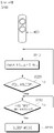
- FIG. 27 shows an example of operation of an image display apparatus included in a sleep management system according to another embodiment.
- the image display apparatus 300 obtains a sleep state SS of a user (3010).
- the sleep data acquisition apparatus 100 may detect a heart rate, respiration rate, and movement of the user every predetermined time interval and transmit sleep data SD corresponding to the user's heart rate, respiration rate, and movement to the image display apparatus 300 or the sleep management server SV.
- the image display apparatus 300 may directly determine the sleep state SS, or may obtain the sleep state SS from the sleep management server SV.
- the image display apparatus 300 may obtain the user's heart rate, respiration rate, and movement from the sleep data SD and determine whether the user lies on a bed, whether the user falls asleep, in which sleep stage the user is, whether the user wakes up briefly while sleeping, whether the user falls asleep again, whether the user completely wakes up, whether the user gets out of the bed, and the like on the basis of the obtained heart rate, respiration rate, and movement,.
- the image display apparatus 300 may receive a sleep state SS, such as whether the user lies on a bed, whether the user falls asleep, in which sleep stage the user is, whether the user wakes up briefly while sleeping, whether the user falls asleep again, whether the user completely wakes up, whether the user gets out of the bed, and the like from the sleep management server SV.
- a sleep state SS such as whether the user lies on a bed, whether the user falls asleep, in which sleep stage the user is, whether the user wakes up briefly while sleeping, whether the user falls asleep again, whether the user completely wakes up, whether the user gets out of the bed, and the like from the sleep management server SV.
- the image display apparatus 300 determines whether the user falls asleep on the basis of the sleep state SS of the user (3020).
- the image display apparatus 300 may obtain the sleep state SS of the user. In this case, the image display apparatus 300 may determine whether the sleep state SS of the user is changed from an awake state to an asleep state.
- the image display apparatus 300 When the user does not fall asleep (no in 3020), the image display apparatus 300 repeatedly determines the sleep state SS of the user.
- the image display apparatus 300 determines whether a first time passes (3030).
- the image display apparatus 300 may determine whether the first time passes after the user is detected as falling asleep.
- the image display apparatus 300 waits for the first time to pass.
- Sleep of the user may be disturbed by an external stimulus immediately after the user falls asleep. For example, when a volume of a sound output by the image display apparatus 300 changes immediately after the user falls asleep, the user may not fall asleep but may wake due to the change in the sound volume.
- the image display apparatus 300 may wait for the first time after the user is detected as falling asleep.
- the image display apparatus 300 lowers the volume (3035).
- the image display apparatus 300 may decrease the volume of the output sound to a predetermined volume level (a value of "0" or higher) at once or step by step.
- the image display apparatus 300 may decrease a brightness of an image output by the image display apparatus 300 as well as decreasing the volume of the output sound.
- the image display apparatus 300 determines whether a second time passes (3040).
- the image display apparatus 300 may determine whether the second time passes after the user is detected as falling asleep.
- the image display apparatus 300 waits for the second time to pass.
- the sleep of the user may be disturbed by an external stimulus immediately after the user falls asleep. For example, when the image display apparatus 300 is turned off immediately after the user falls asleep, the user may not fall asleep but may wake due to the image display apparatus 300 being turned off.
- the image display apparatus 300 may wait for the second time after the user is detected as falling asleep.
- the image display apparatus 300 stops operating (3045). That is, the image display apparatus 300 is turned off.
- FIG. 28 shows another example of operation of an image display apparatus included in a sleep management system according to another embodiment.
- the image display apparatus 300 obtains a sleep state SS of a user (3110).
- the sleep data acquisition apparatus 100 may detect a heart rate, respiration rate, and movement of the user every predetermined time interval and transmit sleep data SD corresponding to the user's heart rate, respiration rate, and movement to the image display apparatus 300 or the sleep management server SV.
- the image display apparatus 300 may directly determine the sleep state SS, or may obtain the sleep state SS from the sleep management server SV.
- the image display apparatus 300 determines whether the user wakes on the basis of the sleep state SS of the user (3120).
- the image display apparatus 300 may obtain the sleep state SS of the user. In this case, the image display apparatus 300 may determine whether the sleep state SS of the user is changed from the asleep state to the awake state.
- the image display apparatus 300 may determine whether the user wakes on the basis of a wake-up time preset by the user in conjunction with the sleep state SS of the user.
- the image display apparatus 300 may determine that the user is awake.
- the image display apparatus 300 determines whether the sleep state SS of the user is maintained as the awake state for a predetermined reference time or longer. When the sleep state SS of the user is maintained as the awake state for the predetermined reference time or longer, the image display apparatus 300 may determine that the user is awake. This is to provide a sufficient sleep time to the user before the wake-up time preset by the user.
- the image display apparatus 300 When the user does not wake up (no in 3120), the image display apparatus 300 repeatedly determines the sleep state SS of the user.
- the image display apparatus 300 When the user wakes up (yes in 3120), the image display apparatus 300 starts to operate (3125). That is, the image display apparatus 300 is turned on.
- an external stimulus may facilitate waking of the user. Accordingly, the image display apparatus 300 is turned on.
- the image display apparatus 300 may determine the sleep state of the user or receive the sleep state of the user and may operate according to the sleep state of the user.
- FIG. 29 shows an example of operation of an air conditioner included in a sleep management system according to another embodiment.
- the air conditioner 400 obtains a sleep state SS of a user (3210).
- the sleep data acquisition apparatus 100 may detect a heart rate, respiration rate, and movement of the user every predetermined time interval and transmit sleep data SD corresponding to the user's heart rate, respiration rate, and movement to the air conditioner 400 or the sleep management server SV.
- the air conditioner 400 may directly determine the sleep state SS, or may obtain the sleep state SS from the sleep management server SV.
- the air conditioner 400 determines whether the user falls asleep on the basis of the sleep state SS of the user (3220).
- the air conditioner 400 may obtain the sleep state SS of the user. In this case, the air conditioner 400 may determine whether the sleep state SS of the user is changed from the awake state to the asleep state.
- the air conditioner 400 When the user does not fall asleep (no in 3220), the air conditioner 400 repeatedly determines the sleep state SS of the user.
- the air conditioner 400 determines whether a first time passes (3230).
- the air conditioner 400 may determine whether the first time passes after the user is detected as falling asleep.
- the air conditioner 400 waits for the first time to pass.
- Sleep of the user may be disturbed by an external stimulus immediately after the user falls asleep.
- the air conditioner 400 operates immediately after the user falls asleep, the user may not fall asleep but may wake due to the sudden operation of the air conditioner 400.
- the air conditioner 400 may wait for the first time after the user is detected as falling asleep.
- the air conditioner 400 When the first time passes after the user falls asleep (yes in 3230), the air conditioner 400 operates in a sleep mode (3235).
- the air conditioner 400 may operate in a predetermined sleep mode.
- the sleep mode is an operation mode of the air conditioner 400 in which the indoor temperature is properly adjusted while the user sleeps.
- a target temperature of the air conditioner 400 may change according to a predetermined profile in the sleep mode, and the sleep mode may be divided into a plurality of stages according to a profile of the target temperature.
- the sleep mode may include a sleep induction stage in which sleep of the user is induced, a sleep maintenance step in which the sleep of the user is maintained, and a wake-up induction stage in which waking of the user is induced.
- FIG. 30 shows another example of operation of an air conditioner included in a sleep management system according to another embodiment.
- Operation 3300 of an image display apparatus 300 will be described with reference to FIG. 30 .
- An air conditioner 400 obtains a sleep state SS of a user (3310).
- a sleep data acquisition apparatus 100 may detect a heart rate, respiration rate, and movement of the user every predetermined time interval and transmit sleep data SD corresponding to the user's heart rate, respiration rate, and movement to the image display apparatus 300 or a sleep management server SV.
- the air conditioner 400 may directly determine the sleep state SS, or may receive the sleep state SS from the sleep management server SV.
- the air conditioner 400 determines whether the user wakes on the basis of the sleep state SS of the user (3320).
- the air conditioner 400 may obtain the sleep state SS of the user. In this case, the air conditioner 400 may determine whether the sleep state SS of the user is changed from an asleep state to an awake state.
- the air conditioner 400 may determine whether the user wakes on the basis of a wake-up time preset by the user in conjunction with the sleep state SS of the user.
- the air conditioner 400 may determine that the user is awake.
- the air conditioner 400 determines whether the sleep state SS of the user is maintained as the awake state for a predetermined reference time or longer. When the sleep state SS of the user is maintained as the awake state for the predetermined reference time or longer, the air conditioner 400 may determine that the user is awake. This is to provide a sufficient sleep time to the user before the wake-up time preset by the user.
- the air conditioner 400 When the user does not wake up (no in 3320), the air conditioner 400 repeatedly determines the sleep state SS of the user.
- the air conditioner 400 switches an operation mode from a sleep mode to a normal mode (3325).
- the air conditioner 400 may be switched to the normal mode.
- the air conditioner 400 determines whether the user gets out of bed (3330).
- the air conditioner 400 may directly determine the sleep state SS, or may receive the sleep state SS from the sleep management server SV. Also, the air conditioner 400 may determine whether the user gets out of bed on the basis of the sleep state SS of the user.
- the air conditioner 400 stops operating (3335). That is, the air conditioner 400 is turned off.
- the user terminal 200 may determine that the user no longer wants to continue sleeping, and thus may stop the operation of the air conditioner 400. Accordingly, the air conditioner 400 is turned off.
- the air conditioner 400 may determine or receive the sleep state of the user, and operate according to the sleep state of the user.
Description
- The present disclosure relates to a user terminal and a sleep management method, and more particularly, to a user terminal and a sleep management method that obtains sleep information of a user in a non-contact manner.
- Generally, home network systems detect a state or operation of a user and control operation of various electronic devices depending on the state or operation of the user.
- To this end, electronic devices of home network systems generally include various sensors.
- For example, some electronic devices may obtain a facial image of a user using a camera, process the user's facial image, and estimate an emotion of the user.
- Also, other electronic devices may obtain movement of a user and then operate depending on the user's movement.
- In particular, recently, research is being actively conducted on sensor technology for detecting whether a user is sleeping.
- An aspect of the present disclosure is directed to providing a user terminal and a sleep management method that are capable of determining a sleep state of a user.
- Another aspect of the present disclosure is directed to providing a user terminal and a sleep management method that are capable of providing sleep information of a user.
- Another aspect of the present disclosure is directed to providing a user terminal and a sleep management method that are capable of controlling operation of a home appliance according to a sleep state of a user.
US 20140371635 A1 relates to methods and apparatus for predicting and monitoring abnormal physiological conditions by non-contact measurement and analysis of characteristics of physiological and/or physical parameters.US 20130267791 A1 relates to methods and apparatus for predicting and monitoring abnormal physiological conditions by non-contact measurement and analysis of characteristics of physiological and/or physical parameters.JP 2012202659 A - The invention is set out in the appended set of claims.
- According to an aspect of the present disclosure, it is possible to provide a user terminal and a sleep management method that are capable of determining a sleep state of a user.
- According to another aspect of the present disclosure, it is possible to provide a user terminal and a sleep management method that are capable of providing sleep information of a user to the user.
- According to another aspect of the present disclosure, it is possible to provide a user terminal and a sleep management method that are capable of controlling operation of a home appliance according to a sleep state of a user.
-
-
FIG. 1 shows an example of a configuration of a sleep management system according to an embodiment. -
FIG. 2 shows another example of a configuration of a sleep management system according to an embodiment. -
FIG. 3 shows an example of operation of a sleep management system according to an embodiment. -
FIG. 4 shows an example of a user's sleep cycle shown inFIG. 3 . -
FIG. 5 shows a configuration of a sleep data acquisition apparatus included in a sleep management system according to an embodiment. -
FIG. 6 shows a configuration of a user terminal included in a sleep management system according to an embodiment. -
FIG. 7 shows an example of communication between a sleep management system and home appliances according to an embodiment. -
FIG. 8 shows another example of communication between a sleep management system and home appliances according to an embodiment. -
FIG. 9 shows an example of interoperation between a sleep management system and an image display apparatus according to an embodiment. -
FIG. 10 shows operation of an image display apparatus during the interoperation shown inFIG. 9 . -
FIG. 11 shows another example of interoperation between a sleep management system and an image display apparatus according to an embodiment. -
FIG. 12 shows operation of an image display apparatus during the interoperation shown inFIG. 11 . -
FIG. 13 shows an example of interoperation between a sleep management system and an air conditioner according to an embodiment. -
FIG. 14 shows an example of operation of the air conditioner during the interoperation shown inFIG. 13 . -
FIG. 15 shows an example of operation of the air conditioner in a sleep mode. -
FIG. 16 shows another example of interoperation between a sleep management system and an air conditioner according to an embodiment. -
FIG. 17 shows operation of the air conditioner during the interoperation shown inFIG. 16 . -
FIG. 18 shows an example of a sleep information display screen displayed on a user terminal according to an embodiment. -
FIG. 19 shows an example of a home appliance setting screen displayed on a user terminal according to an embodiment. -
FIG. 20 shows an example of an air conditioner setting screen displayed on a user terminal according to an embodiment. -
FIG. 21 shows an example of an image display apparatus setting screen display on a user terminal according to an embodiment. -
FIG. 22 shows an example of a sleep environment setting screen displayed on a user terminal according to an embodiment. -
FIG. 23 shows an example of an indoor temperature setting screen displayed on a user terminal according to an embodiment. -
FIG. 24 shows a change in indoor temperature caused by the indoor temperature setting screen shown inFIG. 23 . -
FIG. 25 shows an example of communication between a sleep management system and home appliances according to another embodiment. -
FIG. 26 shows another example of communication between a sleep management system and home appliances according to another embodiment. -
FIG. 27 shows an example of operation of an image display apparatus included in a sleep management system according to another embodiment. -
FIG. 28 shows another example of operation of an image display apparatus included in a sleep management system according to another embodiment. -
FIG. 29 shows an example of operation of an air conditioner included in a sleep management system according to another embodiment. -
FIG. 30 shows another example of operation of an air conditioner included in a sleep management system according to another embodiment. - The configurations shown in the embodiments and drawings described herein are merely examples of preferred embodiments of the present disclosure, and there may be various modifications at the time of filing of the present application that replace the embodiments and drawings.
- The terminology used herein is for the purpose of describing particular embodiments only and is not intended to limit the scope of the present disclosure.
- Specifically, the singular forms "a," "an," and "the" include the plural forms as well, unless the context clearly dictates otherwise.
- Also, the terms "comprises," "includes," or "has," when used herein, should be understood as specifying the presence of stated features, integers, steps, operations, elements, components, or combinations thereof and not precluding the presence or addition of one or more other features, integers, steps, operations, elements, components, or combinations thereof.
- In addition, terms including ordinals such as "first," "second," and the like used in the present specification may be used to describe various elements, but these elements are not limited by the terms. These terms are used to only distinguish one element from another element.
- Also, terms such as "unit," "-er," "-or," "block," "member," "module," and the like used in the present specification may represent a unit which processes at least one function or operation. For example, the terms may represent hardware such as a field-programmable gate array (FPGA) or an application specific integrated circuit (ASIC), software stored in a memory, or one or more processes processed by a processor.
- Hereinafter, an embodiment of the present disclosure will be described in detail with reference to the accompanying drawings. The same reference numeral or symbol shown in the accompanying drawings may represent a part or an element for performing substantially the same function.
-
FIG. 1 shows an example of a configuration of a sleep management system according to an embodiment, andFIG. 2 shows another example of a configuration of a sleep management system according to an embodiment. - As shown in
FIG. 1 , asleep management system 1 according to an embodiment may include a sleepdata acquisition apparatus 100 configured to obtain sleep-related data SD (hereinafter referred to as sleep data) of a user, and auser terminal 200 configured to obtain sleep-related information (hereinafter referred to as sleep information) of the user on the basis of the sleep data SD. In this case, the sleep information may include sleep time information related to a sleep time of a user U, and sleep summary information to be displayed to the user U. - The sleep
data acquisition apparatus 100 may collect the sleep data SD of the user while the user is sleeping, falling asleep, or waking up. Also, the sleepdata acquisition apparatus 100 may transmit the sleep data SD of the user to theuser terminal 200. - In detail, the sleep
data acquisition apparatus 100 may detect a heart rate, respiration rate, and movement of the user and generate sleep data SD corresponding to the user's heart rate, respiration rate, and movement. For example, the sleepdata acquisition apparatus 100 may detect a vibration caused by the user's heart rate, respiration rate, and movement and generate sleep data SD corresponding to the detected vibration. - Also, the sleep
data acquisition apparatus 100 may transmit pieces of sleep data SD generated every predetermined time interval to theuser terminal 200 in a wireless manner. - The
user terminal 200 may receive the sleep data SD of the user from the sleepdata acquisition apparatus 100, and may obtain a sleep state SS of the user or sleep information SI of the user on the basis of the received sleep data SD. - For example, the
user terminal 200 may obtain the sleep state SS of the user U. In detail, theuser terminal 200 may determine whether the user U is lying on a bed B, whether the user U is sleeping, in which sleep stage the user U is, whether the user U wakes up briefly while sleeping, whether the user U is falling asleep again, whether the user U completely wakes up, whether the user U gets out of the bed B, and the like. - Also, the
user terminal 200 may obtain sleep time information such as a time at which the user U lies on the bed B, a time at which the user U falls asleep, a time at which the sleep stage of the user U changes, a time at which the user U wakes up briefly while sleeping, a time at which the user U falls asleep again, a time at which the user U wakes up, and a time at which the user U gets out of the bed B on the basis of the sleep state SS of the user U. - Also, the
user terminal 200 may process the sleep time information of the user U, generate sleep summary information, and display the sleep summary information to the user U. For example, theuser terminal 200 may display a total sleep time, a time it takes the user to fall asleep, the number of times the user wakes up while sleeping, sleep efficiency, a deep sleep time, a rapid eye movement (REM) sleep time, or the like of the user on the basis of the sleep data SD of the user. - However, the configuration of the
sleep management system 1 is not limited to that shown inFIG. 1 . - For example, as shown in
FIG. 2 , thesleep management system 1 may further include a sleep management server SV in addition to the sleepdata acquisition apparatus 100 and theuser terminal 200. - The sleep management server SV may receive the sleep data SD from the
user terminal 200, process the received sleep data SD, and generate the sleep state SS or the sleep information SI of the user U. Also, the sleep management server SV may transmit the sleep state SS or the sleep information SI of the user U to theuser terminal 200. - In other words, when the sleep data SD is obtained from the sleep
data acquisition apparatus 100, theuser terminal 200 may transmit the obtained sleep data SD to the sleep management server SV over a wide area network (WAN) and receive the sleep state SS or the sleep information SI of the user U from the sleep management server SV. Also, when the sleep state SS of the user U is received from the sleep management server SV, theuser terminal 200 may generate the sleep information SI of the user U on the basis of the sleep state SS of the user U. - In particular, the sleep management server SV may obtain sleep data of a plurality of users from a plurality of user terminals, process the sleep data, and generate sleep information of the plurality of users. In this case, the sleep management server SV may manage the sleep information of the plurality of users on a user basis.
- In addition, the sleep management server SV may manage the sleep information SI of the plurality of users on a group basis, wherein the groups are set by the users. For example, when the plurality of users are set as family members, the sleep management server SV may transmit sleep information of the family members (the plurality of users) to user terminals of the family members so that the family members can share the sleep information.
- Operation of the
sleep management system 1 will be described in detail below with reference to the following example. -
FIG. 3 shows an example of operation of a sleep management system according to an embodiment, andFIG. 4 shows an example of a user's sleep cycle shown inFIG. 3 . - As shown in
FIG. 3 , the sleepdata acquisition apparatus 100 may be placed near a user U who is lying on a bed B. For example, as shown inFIG. 3 , the sleepdata acquisition apparatus 100 may be placed under the bed B of the user U. However, the placement of the sleepdata acquisition apparatus 100 is not limited to that shown inFIG. 3 , and the sleepdata acquisition apparatus 100 may be placed wherever a heart rate, respiration rate, and movement of the user U can be detected. - Also, the
user terminal 200 may be placed near the sleepdata acquisition apparatus 100. For example, as shown inFIG. 3 , theuser terminal 200 may be placed on a table T provided near the bed B of the user U. However, the placement of theuser terminal 200 is not limited to that shown inFIG. 3 , and theuser terminal 200 may be placed wherever the sleep data SD can be received from the sleepdata acquisition apparatus 100. - As shown in
FIG. 3 , when the user U lies on the bed B, the sleepdata acquisition apparatus 100 may detect a heart rate, respiration rate, and movement of the user U who is lying on the bed B and transmit sleep data SD corresponding to the user U's heart rate, respiration rate, and movement to theuser terminal 200. Also, theuser terminal 200 may determine a time at which the user U lies on the bed B on the basis of the sleep data SD or by using the sleep management server SV. - For example, the sleep
data acquisition apparatus 100 can detect an amount of vibration less than a reference value, which is caused in daily life of the user U, before the user U lies on the bed B. However, the sleepdata acquisition apparatus 100 may interpret the amount of vibration less than the reference value as meaningless noise and not transmit data corresponding to the amount of vibration less than the reference value to theuser terminal 100. As a result, theuser terminal 200 may not receive sleep data from the sleepdata acquisition apparatus 100 before the user U lies on the bed B. - On the other hand, the
user terminal 200 may detect an amount of vibration greater than or equal to the reference value when the user U lies on the bed B. The sleepdata acquisition apparatus 100 may transmit sleep data corresponding to the amount of vibration greater than or equal to the reference value to theuser terminal 200. - When the sleep data is received from the sleep
data acquisition apparatus 100, theuser terminal 200 or the sleep management server SV may determine that the user U is lying on the bed B and determine a start time of the reception of the sleep data as a time at which the user U lies on the bed B. - Also, when the user U falls asleep, the sleep
data acquisition apparatus 100 may detect a heart rate, respiration rate, and movement of the user U who is sleeping and transmit sleep data SD corresponding to the user U's heart rate, respiration rate, and movement to theuser terminal 200. Also, theuser terminal 200 may determine a time at which the user U falls asleep on the basis of the sleep data SD or by using the sleep management server SV. - In detail, the user U may not fall asleep as soon as the user U lies on the bed B and may not fall asleep for a short period of several minutes or for several hours. Accordingly, the time at which the user U lies on the bed B may be different from the time at which the user falls asleep.
- Also, the user U has a different heart rate, respiration rate, and movement when he or she is awake than when he or she is asleep. In detail, it is well known that a person has a decreased heart rate and respiration rate while sleeping.
- Accordingly, when the sleep data is received from the sleep
data acquisition apparatus 100, theuser terminal 200 or the sleep management server SV may determine whether the user U is awake or asleep on the basis of the user U's heart rate, respiration rate, and movement and determine the time at which the user falls asleep on the basis of a result of the determination of whether the user U is awake or asleep. - Also, while the user U is sleeping, the sleep
data acquisition apparatus 100 may detect the user U's heart rate, respiration rate, and movement every predetermined time interval and transmit sleep data SD corresponding to the user U's heart rate, respiration rate, and movement to theuser terminal 200. - On the basis of the sleep data SD of the user U during sleep, the
user terminal 200 or the sleep management server SV may determine a sleep stage of the user U and determine whether the user U consciously or unconsciously wakes up. - It is well known that a person does not suddenly fall asleep, maintain deep sleep, and then suddenly wake up, but that human sleep includes certain stages and cycles. For example, as shown in
FIG. 4 , human sleep gradually proceeds to a deep sleep stage after falling sleep. Subsequently, human sleep repeatedly alternates between a light sleep stage and the deep sleep stage. - As is already well known, human sleep may be largely divided into REM sleep and non-REM sleep, and REM sleep may be divided into a total of four stages.
- It is well known that REM sleep makes up about 20% to 25% of the entire sleep, and during REM sleep, a characteristic electroencephalogram (EEG) exists, muscle tension is reduced to the lowest level and characteristic REM is observed.
- In particular, a significant change occurs in heart rate and respiration rate during REM sleep.
- Also, non-REM sleep may be divided into a first stage, a second stage, a third stage, and a fourth stage, as described above. Sleep in the third stage and the fourth stage is typically referred to as deep sleep, and sleep in the first stage and the second stage is typically referred to as light sleep. Here, it is known that the deep sleep makes up about 15 to 20% of the entire sleep.
- During non-REM sleep, muscle tension is reduced and human movement is also reduced.
- In particular, it is known that a heart rate and a respiration rate during non-REM sleep are decreased further than during waking and are relatively regular.
- As described above, human sleep exhibits a characteristic heart rate, respiration rate, and movement in each of the stages. Thus, the
user terminal 200 or the sleep management server SV may determine a sleep stage of the user U on the basis of the sleep data SD indicating the user U's heart rate, respiration rate, and movement during sleep. - For example, the
user terminal 200 or the sleep management server SV may determine whether the sleep of the user U enters or exits a REM sleep stage, and may determine and/or store a time at which the REM sleep stage is entered and a time at which the REM sleep stage is exited. - As another example, the
user terminal 200 or the sleep management server SV may determine whether the sleep of the user U enters or exits deep sleep stages (the third and fourth stages) of non-REM sleep, and may determine and/or store a time at which the deep sleep stage is entered and a time at which the deep sleep stage is exited. - Also, it is known that a sleeping person consciously or unconsciously wakes up. For example, as shown in
FIG. 4 , a person enters a waking stage during REM sleep. Also, in the waking stage, a person may consciously or unconsciously wake up, and, while waking, his or her heart rate and respiration rate increase, and his or her movement becomes active. - Accordingly, the
user terminal 200 or the sleep management server SV may determine whether the user U wakes from sleep on the basis of the sleep data SD indicating the user U's heart rate, respiration rate, and movement during sleep. - For example, the
user terminal 200 or the sleep management server SV may determine whether the user U wakes from the sleep, and may determine and/or store a time at which the user U wakes up. Also, when the user U falls asleep again within a reference time (e.g., 30 minutes) after waking up, theuser terminal 200 or the sleep management server SV may determine that the user U continues to sleep, and may determine and/or store a time at which the user U falls asleep again. - Also, when sleep is completed, the user U may wake up and then get out of the bed B. When the user U wakes up and gets out of the bed B, the
user terminal 200 or the sleep management server SV may determine whether the user U wakes up and whether the user U gets out of the bed B on the basis of the sleep data SD received from the sleepdata acquisition apparatus 100. Also, theuser terminal 200 or the sleep management server SV may determine and/or store a time at which the user U wakes up and a time at which the user U gets out of the bed B. - As described above, the
user terminal 200 or the sleep management server SV may obtain the sleep information SI of the user U on the basis of the sleep data SD. In detail, theuser terminal 200 or the sleep management server SV may obtain sleep time information such as a time at which the user U lies on the bed B, a time at which the user U falls asleep, a time at which the sleep stage of the user U changes, a time at which the user U wakes up briefly while sleeping, a time at which the user U falls asleep again, a time at which the user U wakes up, and a time at which the user U gets out of the bed B. - Also, the
user terminal 200 or the sleep management server SV may generate sleep summary information of the user U on the basis of the sleep time information of the user U. For example, theuser terminal 200 or the sleep management server SV may obtain sleep summary information such as a total sleep time, a time it takes the user to fall asleep, the number of times the user wakes up while sleeping, sleep efficiency, a deep sleep time, and a REM sleep time on the basis of the sleep time information of the user U. - Also, the
user terminal 200 may display the sleep summary information to the user according to input of the user. - Configurations of the sleep
data acquisition apparatus 100 and theuser terminal 200 included in thesleep management system 1 will be described below. -
FIG. 5 shows a configuration of a sleep data acquisition apparatus included in a sleep management system according to an embodiment. - As shown in
FIG. 5 , the sleepdata acquisition apparatus 100 may include asleep sensor 120, asensor communicator 130, and asensor controller 110. - The
sleep sensor 120 may detect a heart rate, a respiration rate, and a movement of a user who is lying on a bed and output an electrical signal corresponding to the detected heart rate, respiration rate, and movement of the user to thesensor controller 110. - For example, the
sleep sensor 120 may include apiezoelectric sensor 121 configured to detect pressure caused by the heart rate, respiration rate, and movement of the user and output an electrical signal corresponding to the detected pressure. Thepiezoelectric sensor 121 uses a piezoelectric effect in which electric polarization occurs on a surface of a crystal when a force is applied to the crystal. Thepiezoelectric sensor 121 generates an alternating current (AC) voltage when pressure is applied thereto, and generates a vibration when the AC voltage is applied thereto. - In detail, when pressure is applied to the
piezoelectric sensor 121 by the heart rate, respiration rate, and movement of the user, thepiezoelectric sensor 121 may output an electrical signal corresponding to the pressure applied thereto. - As another example, the
sleep sensor 120 may include anacceleration sensor 123 configured to detect a vibration caused by the heart rate, respiration rate, and movement of the user and output an electrical signal corresponding to the detected vibration. - The
acceleration sensor 123 is a sensor configured to measure a change in speed per unit time. When theacceleration sensor 123 is moved or vibrated by the heart rate, respiration rate, and movement of the user, theacceleration sensor 123 may output an electrical signal corresponding to the movement or vibration. - However, the
sleep sensor 120 does not have to include both of thepiezoelectric sensor 121 and theacceleration sensor 123. Depending on a designer's selection, thesleep sensor 120 may include either thepiezoelectric sensor 121 or theacceleration sensor 123. - The
sensor communicator 130 may include a short-range communication module 131 configured to transmit and/or receive data to and/or from theuser terminal 200. - The short-
range communication module 131 may communicate with a communication partner through various communication schemes. For example, the short-range communication module 131 may communicate with a communication partner through a WiFi communication scheme (IEEE 802.11), a Bluetooth communication scheme (IEEE 802.15.1), a Zigbee communication scheme (IEEE 802.15.4), or the like. - However, the short-
range communication module 131 does not employ all of the WiFi communication scheme, the Bluetooth communication scheme, and the Zigbee communication scheme, and may employ at least one of the WiFi communication scheme, the Bluetooth communication scheme, and the Zigbee communication scheme. - The
sensor controller 110 may include amemory 113 configured to store and/or recall programs and data, and aprocessor 111 configured to process the data according to the programs stored in thememory 113 and control thesleep sensor 120 and thesensor communicator 130. - The
memory 113 may store a control program and control data for controlling operation of the sleepdata acquisition apparatus 100, or may recall sleep data SD obtained through thesleep sensor 120. - The
memory 113 may include a volatile memory such as a static random access memory (S-RAM) and a dynamic RAM (D-RAM) and a non-volatile memory such as a read-only memory (ROM), an erasable programmable ROM (EPROM), an electrically erasable programmable ROM (EEPROM), and a flash memory. - The volatile memory, which is a memory that loses data recalled therein when power is cut off, may temporarily recall programs and data. For example, the volatile memory may recall a control program and control data or recall the sleep data SD obtained by the
sleep sensor 120. - The non-volatile memory, which is a memory that maintains data stored therein even though power is cut off, may semi-permanently store programs and data. For example, the non-volatile memory may store a control program and control data for controlling operation of the sleep
data acquisition apparatus 100. - The
processor 111 may process the sleep data SD input from thesleep sensor 120 according to the control program and control data stored in thememory 113 and transmit the sleep data to theuser terminal 200 through thesensor communicator 130. - For example, the
processor 111 may obtain an electrical signal output by thesleep sensor 120 every predetermined time interval and generate the sleep data SD by digitalizing the obtained electrical signal. Also, theprocessor 111 may output the sleep data SD and a control signal to thesensor communicator 130 so that thesensor communicator 130 can transmit the sleep data SD to theuser terminal 200. - As described above, the
sensor controller 110 may control operation of thesleep sensor 120 and thesensor communicator 130 included in the sleepdata acquisition apparatus 100. An operation of the sleepdata acquisition apparatus 100, which will be described below, may be interpreted as being controlled by thesensor controller 110. -
FIG. 6 shows a configuration of a user terminal included in a sleep management system according to an embodiment. - As shown in
FIG. 6 , theuser terminal 200 may include a user input/output unit 220, aterminal communicator 230, aterminal storage 240, and aterminal controller 210. - The user input/
output unit 220 may receive a user input from a user and output information corresponding to the user input. - For example, the user input/
output unit 220 may include atouch screen module 221 configured to receive a touch input from a user and display information corresponding to the received touch input, abutton module 223 configured to receive a predetermined user input from the user, amicrophone 225 configured to receive a voice input from the user, and aspeaker 227 configured to output sounds. - The
touch screen module 221 may receive a touch input from a user and display image information corresponding to the received touch input. - In detail, the
touch screen module 221 may receive at least one touch or a continuous touch movement through the user's body (e.g., his or her finger) or a touchable input means (e.g., a stylus pen). - The
touch screen module 221 may convert the touch input of the user into a digital signal corresponding to the touch input (e.g., an x coordinate and a y coordinate) and output the digital signal to theterminal controller 210. - The
touch screen module 221 may be implemented as a resistive-type module, a capacitive-type module, an infrared-type module, or an acoustic-wave-type module. - The
button module 223 may be provided on a front surface, a side surface, or a rear surface of a housing of theuser terminal 200, and may include a plurality of buttons capable of receiving a predetermined user input. Thebutton module 223 may include at least one of a power/lock button, a volume button, a menu button, a home button, and a return button. - The
terminal communicator 230 may transmit and/or receive data to and/or from the sleepdata acquisition apparatus 100 and the sleep management server SV, which have been described above. In addition, theterminal communicator 230 may transmit and/or receive data to and/or from other user terminals. - The
terminal communicator 230 may include a short-range communication module 231 configured to transmit and/or receive data to and/or from a communication partner at a location that is relatively near the communication partner, and amobile communication module 233 configured to transmit and/or receive data to and/or from a communication partner regardless of a distance from the communication partner. - The short-
range communication module 231 may communicate with a communication partner through various communication schemes. For example, the short-range communication module 231 may communicate with a communication partner through a WiFi communication scheme (IEEE 802.11), a Bluetooth communication scheme (IEEE 802.15.1), a Zigbee communication scheme (IEEE 802.15.4), or the like - However, the short-
range communication module 231 does not employ all of the WiFi communication scheme, the Bluetooth communication scheme, and the Zigbee communication scheme, and may employ at least one of the WiFi communication scheme, the Bluetooth communication scheme, and the Zigbee communication scheme. - The
mobile communication module 233 may communicate with a communication partner through various communication schemes. For example, themobile communication module 233 may communicate with the communication partner by using a second generation communication scheme such as time division multiple access (TDMA) and code division multiple access (CDMA), a third generation communication scheme such as wideband code division multiple access (WCDMA), code division multiple access 2000 (CDMA2000), wireless broadband (Wibro), and world interoperability for microwave access (WiMAX), a fourth generation communication scheme such as long term evolution (LTE) and wireless broadband evolution, or the like. - Various application programs and data for performing various functions may be stored in the
terminal storage 240 according to a user input received through the user input/output unit 220. For example, an operating system (OS) program for managing configurations and resources (software and hardware) included in theuser terminal 200, a video playback program for playing a video and displaying a picture, a word processor program for creating and editing a document, a browser for accessing a WAN such as the Internet, and the like may be stored in theterminal storage 240. - The
terminal storage 240 may include a non-volatile memory in which no program or data is lost even when power is cut off. For example, theterminal storage 240 may include a flash memory for easily writing and erasing data or the like. - The
terminal controller 210 may include amemory 213 configured to store and/or recall programs and data, and aprocessor 211 configured to process data according to the program stored in thememory 213 and control the user input/output unit 220, theterminal communicator 230, and theterminal storage 240. - The
memory 213 may store a control program and control data for controlling operation of theuser terminal 200, or may recall a user input received through the user input/output unit 220, communication data received through theterminal communicator 230, an application program loaded from theterminal storage 240, and the like. - The
memory 213 may include a volatile memory such as an S-RAM and a D-RAM and a non-volatile memory such as a ROM, an EPROM, an EEPROM, and a flash memory. - The volatile memory, which is a memory that loses data stored therein when power is cut off, may temporarily store programs and data. The volatile memory may recall an application program or may recall the sleep data SD received from the sleep
data acquisition apparatus 100. - The non-volatile memory, which is a memory capable of maintaining data stored therein even though power is cut off, may semi-permanently store programs and data. For example, the non-volatile memory may store a booting program and data for booting the
user terminal 200 and the sleep data SD received from the sleepdata acquisition apparatus 100. - The
processor 211 may process data according to a program recalled in thememory 213 and control the user input/output unit 220, theterminal communicator 230, and theterminal storage 240 according to the processed data. - For example, the
processor 211 may process the sleep data SD received through theterminal communicator 230 to generate sleep time information of the user. Also, theprocessor 211 may process the sleep time information of the user to generate sleep summary information of the user. Also, theprocessor 211 may output the sleep summary information of the user and a control signal to the user input/output unit 220 so that the sleep summary information can be displayed through thetouch screen module 221. - As another example, the
processor 211 may output the sleep data SD and a control signal to theterminal communicator 230 so that the sleep data SD can be transmitted to the sleep management server SV. Also, when the sleep information SI is received from the sleep management server SV, theprocessor 211 may obtain the sleep summary information from the sleep information SI. Also, theprocessor 211 may output the sleep summary information and a control signal to the user input/output unit 220 so that the sleep summary information can be displayed through thetouch screen module 221. - As described above, the
terminal controller 210 may control operation of the user input/output unit 220, theterminal communicator 230, and theterminal storage 240 included in theuser terminal 200. - An operation of the
user terminal 200, which will be described below, may be interpreted as being controlled by theterminal controller 210. - In particular, the control operation of the
terminal controller 210 may be implemented as a sleep management application program. The user may download an application program through a WAN or a local area network (LAN). When the user executes the sleep management application program, theterminal controller 210 may execute a control operation that will be described below. - Configurations and operations of the sleep
data acquisition apparatus 100 and theuser terminal 200 included in thesleep management system 1 have been described above. - Interoperation between the
sleep management system 1 and a home appliance will be described below. -
FIG. 7 shows an example of communication between a sleep management system and home appliances according to an embodiment, andFIG. 8 shows another example of communication between a sleep management system and home appliances according to an embodiment. - As shown in
FIGS. 7 and8 , the sleepdata acquisition apparatus 100 may transmit sleep data SD obtained from a user to theuser terminal 200 in a non-contact manner. - When the sleep data SD is received, the
user terminal 200 may process the sleep data SD to determine a sleep state SS. - Also, the
user terminal 200 may transmit controls signals CS1, CS2, and CS3 for controllinghome appliances home appliances - For example, the
user terminal 200 may transmit a control signal for decreasing a volume of a sound output by animage display apparatus 300 or stopping operation of theimage display apparatus 300 to theimage display apparatus 300. Also, theuser terminal 200 may transmit a control signal for changing an operation mode of anair conditioner 400 or changing a target temperature of theair conditioner 400 to theair conditioner 400. Also, theuser terminal 200 may transmit a control signal for delaying operation of arefrigerator 500 to therefrigerator 500. - In this case, as shown in
FIG. 7 , the sleepdata acquisition apparatus 100 and theuser terminal 200 may communicate with each other on a one-to-one basis, and theuser terminal 200 and thehome appliances - Also, as shown in
FIG. 8 , the sleepdata acquisition apparatus 100, theuser terminal 200, and thehome appliances - A detailed example of the interoperation between the sleep
data acquisition apparatus 100, theuser terminal 200, and thehome appliances -
FIG. 9 shows an example of interoperation between a sleep management system and an image display apparatus according to an embodiment, andFIG. 10 shows operation of an image display apparatus during the interoperation shown inFIG. 9 . -
Interoperation 1000 between the sleepdata acquisition apparatus 100, theuser terminal 200, and theimage display apparatus 300 will be described with reference toFIGS. 9 and10 . - The
user terminal 200 receives the sleep data SD from the sleep data acquisition apparatus 100 (1005). - The sleep
data acquisition apparatus 100 may detect a user's heart rate, respiration rate, and movement every predetermined time interval and transmit sleep data SD corresponding to the user's heart rate, respiration rate, and movement to theuser terminal 200. - The sleep
data acquisition apparatus 100 may transmit the sleep data SD to theuser terminal 200 whenever the user's heart rate, respiration rate, and movement are detected or whenever a request for the sleep data SD is received from theuser terminal 200 in addition to every predetermined time interval. - The
user terminal 200 obtains a sleep state SS of the user on the basis of the sleep data SD (1010). - Also, the
user terminal 200 may directly determine the sleep state SS of the user on the basis of the sleep data SD or may receive the sleep state SS through the sleep management server SV. - For example, the
user terminal 200 may obtain the user's heart rate, respiration rate, and movement from the sleep data SD and determine whether the user lies on a bed, whether the user falls asleep, in which sleep stage the user is, whether the user wakes up briefly while sleeping, whether the user falls asleep again, whether the user completely wakes up, whether the user gets out of bed, and the like on the basis of the obtained heart rate, respiration rate, and movement. - As another example, the
user terminal 200 may transmit the sleep data SD to the sleep management server SV and may receive the sleep state SS, such as whether the user lies on a bed, whether the user falls asleep, in which sleep stage the user is, whether the user wakes up briefly while sleeping, whether the user falls asleep again, whether the user completely wakes up, and whether the user gets out of bed, from the sleep management server SV. - The
user terminal 200 determines whether the user falls asleep on the basis of the sleep state SS of the user (1020). - As described above, the
user terminal 200 may obtain the sleep state SS of the user. In this case, theuser terminal 200 may determine whether the sleep state SS of the user is changed from an awake state to an asleep state. - When the user is not asleep (no in 1020), the
user terminal 200 repeatedly receives the sleep data SD and determines the sleep state of the user. - When the user is asleep (yes in 1020), the
user terminal 200 determines whether a first time T1 passes (1030). - In detail, the
user terminal 200 may determine whether the first time T1 passes after the user is detected as falling asleep (T0). - When the first time T1 does not pass (no in 1030), the
user terminal 200 waits for the first time T1 to pass. - Sleep of the user may be disturbed by an external stimulus immediately after the user falls asleep. For example, when a volume of a sound output by the
image display apparatus 300 changes immediately after the user falls asleep, the user may not fall asleep but may wake up due to the change in the sound volume. - In order to prevent the sleep of the user from being disturbed by an external stimulus, the
user terminal 200 may wait for the first time T1 after the user is detected as falling asleep (T0). - When the first time T1 passes after the user falls asleep (yes in 1030), the
user terminal 200 transmits a sound volume decrease command to the image display apparatus 300 (1035). - When a certain time (e.g., about five minutes) passes after the user falls asleep, the possibility of the sleep of the user being disturbed by a small external stimulus is low. Rather, there is a concern that the user may be interrupted from entering deep sleep by sounds output by the
image display apparatus 300. - Accordingly, the
user terminal 200 may transmit the sound volume decrease command to theimage display apparatus 300 to decrease the volume of the sound output by theimage display apparatus 300. - According to the sound volume decrease command of the
user terminal 200, theimage display apparatus 300 decreases the volume of the output sound (1037). - The
image display apparatus 300 may decrease the volume of the output sound to a predetermined volume level (a value of "0" or higher) at once or step by step. - For example, as shown in
FIG. 10 , when the first time T1 passes after the user is detected as falling asleep (T0), theuser terminal 200 may transmit the sound volume decrease command to theimage display apparatus 300, and theimage display apparatus 300 may decrease the volume of the output sound. - In addition, depending on the case, the
image display apparatus 300 may decrease a brightness of an image output by theimage display apparatus 300 in addition to decreasing the volume of the output sound. - Subsequently, the
user terminal 200 determines whether a second time T2 passes (1040). - In detail, the
user terminal 200 may determine whether the second time T2 passes after the user is detected as falling asleep (T0). - When the second time T2 does not pass (no in 1040), the
user terminal 200 waits for the second time T2 to pass. - The sleep of the user may be disturbed by an external stimulus immediately after the user falls asleep. For example, when the
image display apparatus 300 is turned off immediately after the user falls asleep, the user may not fall asleep but may be woken up by theimage display apparatus 300 being turned off. - In order to prevent the sleep of the user from being disturbed by an external stimulus, the
user terminal 200 may wait for the second time T2 after the user is detected as falling asleep (T0). - When the second time T2 passes after the user falls asleep (yes in 1040), the
user terminal 200 transmits an operation stop command to the image display apparatus 300 (1045). - When a sufficient time (e.g., about 20 minutes) passes after the user falls asleep, the possibility of the sleep of the user being disturbed by a small external stimulus is low. Rather, there is a concern that the user may be interrupted from entering deep sleep by images and sounds output by the
image display apparatus 300. - Accordingly, the
user terminal 200 may transmit the operation stop command to theimage display apparatus 300 to turn off theimage display apparatus 300. - According to the operation stop command of the
user terminal 200, theimage display apparatus 300 stops operating (1047). That is, theimage display apparatus 300 is turned off. - For example, as shown in
FIG. 10 , when the first time T2 passes after the user is detected as falling asleep (T0), theuser terminal 200 may transmit the operation stop command to theimage display apparatus 300, and theimage display apparatus 300 may be turned off. -
FIG. 11 shows another example of interoperation between a sleep management system and an image display apparatus according to an embodiment, andFIG. 12 shows operation of an image display apparatus during the interoperation shown inFIG. 11 . -
Interoperation 1100 between the sleepdata acquisition apparatus 100, theuser terminal 200, and theimage display apparatus 300 will be described with reference toFIGS. 11 and12 . - The
user terminal 200 receives the sleep data SD from the sleep data acquisition apparatus 100 (1105). - The sleep
data acquisition apparatus 100 may detect a user's heart rate, respiration rate, and movement every predetermined time interval and transmit sleep data SD corresponding to the user's heart rate, respiration rate, and movement to theuser terminal 200. - The
user terminal 200 obtains a sleep state SS of the user on the basis of the sleep data SD (1110). - Also, the
user terminal 200 may directly determine the sleep state SS of the user on the basis of the sleep data SD, or may receive the sleep state SS through the sleep management server SV. In detail, theuser terminal 200 may obtain a sleep state, such as whether the user lies on a bed, whether the user falls asleep, in which sleep stage the user is, whether the user wakes up briefly while sleeping, whether the user falls asleep again, whether the user completely wakes up, and whether the user gets out of bed, on the basis of the sleep data SD. - The
user terminal 200 determines whether the user wakes on the basis of the sleep state SS of the user (1120). - As described above, the
user terminal 200 may obtain the sleep state SS of the user on the basis of the sleep data SD of the user. In this case, theuser terminal 200 may determine whether the sleep state SS of the user is changed from the asleep state to the awake state. - Also, the
user terminal 200 may determine whether the user wakes on the basis of a wake-up time preset by the user in conjunction with the sleep state SS of the user. - For example, when it is determined that the sleep state SS of the user is the awake state after the wake-up time preset by the user, the
user terminal 200 may determine that the user is awake. - Also, when it is determined that the sleep state SS of the user is the awake state before the wake-up time preset by the user, the
user terminal 200 determines whether the sleep state SS of the user is maintained as the awake state for a predetermined reference time or longer. When the sleep state SS of the user is maintained as the awake state for the predetermined reference time or longer, theuser terminal 200 may determine that the user is awake. This is to provide a sufficient sleep time to the user before the wake-up time preset by the user. - When the user is not awake (no in 1120), the
user terminal 200 repeatedly receives the sleep data SD and determines the sleep state of the user. - When the user is awake (yes in 1120), the
user terminal 200 transmits an operation start command to the image display apparatus 300 (1125). - When the user wakes, an external stimulus may facilitate the waking of the user. Accordingly, the
user terminal 200 may transmit the operation start command to theimage display apparatus 300 to turn on theimage display apparatus 300. - According to the operation start command of the
user terminal 200, theimage display apparatus 300 starts to operate (1127). That is, theimage display apparatus 300 is turned on. - For example, as shown in
FIG. 12 , when the user wakes up, theuser terminal 200 transmits the operation start command to theimage display apparatus 300 and turns on theimage display apparatus 300. - As described above, the
user terminal 200 may determine the sleep state of the user or receive the sleep state of the user, and may control operation of theimage display apparatus 300 according to the sleep state of the user. -
FIG. 13 shows an example of interoperation between a sleep management system and an air conditioner according to an embodiment, andFIG. 14 shows an example of operation of the air conditioner during the interoperation shown inFIG. 13 . Also,FIG. 15 shows an example of operation of the air conditioner in a sleep mode. -
Interoperation 1200 between the sleepdata acquisition apparatus 100, theuser terminal 200, and theair conditioner 400 will be described with reference toFIGS. 13 ,14 , and15 . - The
user terminal 200 receives the sleep data SD from the sleep data acquisition apparatus 100 (1205). - The sleep
data acquisition apparatus 100 may detect a user's heart rate, respiration rate, and movement every predetermined time interval and transmit sleep data SD corresponding to the user's heart rate, respiration rate, and movement to theuser terminal 200. - The
user terminal 200 obtains a sleep state SS of the user on the basis of the sleep data SD (1210). - Also, the
user terminal 200 may directly determine the sleep state SS of the user on the basis of the sleep data SD, or may receive the sleep state SS through the sleep management server SV. In detail, theuser terminal 200 may obtain a sleep state, such as whether the user lies on a bed, whether the user falls asleep, in which sleep stage the user is, whether the user wakes up briefly while sleeping, whether the user falls asleep again, whether the user completely wakes up, and whether the user gets out of bed, on the basis of the sleep data SD. - The
user terminal 200 determines whether the user falls asleep on the basis of the sleep state SS of the user (1220). - As described above, the
user terminal 200 may obtain the sleep state SS of the user on the basis of the sleep data SD of the user. In this case, theuser terminal 200 may determine whether the sleep state SS of the user is changed from the awake state to the asleep state. - When the user is not asleep (no in 1220), the
user terminal 200 repeatedly receives the sleep data SD and determines the sleep state of the user. - When the user is asleep (yes in 1220), the
user terminal 200 determines whether a first time T1 passes (1230). - When the first time T1 does not pass (no in 1230), the
user terminal 200 waits for the first time T1 to pass. - Sleep of the user may be disturbed by an external stimulus immediately after the user falls asleep. For example, when the
air conditioner 400 operates immediately after the user falls asleep, the user may not fall asleep but may wake due to the sudden operation of theair conditioner 400. - In order to prevent the sleep of the user from being disturbed by an external stimulus, the
user terminal 200 may wait for the first time T1 after the user is detected as falling asleep (T0). - When the first time T1 passes after the user falls asleep (yes in 1230), the
user terminal 200 transmits a sleep mode operation command to the air conditioner 400 (1235). - Properly adjusting an indoor temperature during sleep helps people sleep well. In order to properly adjust an indoor temperature while the user sleeps, the
user terminal 200 may control theair conditioner 400. In detail, theuser terminal 200 may control theair conditioner 400 so that theair conditioner 400 operates in a predetermined sleep mode. The sleep mode of theair conditioner 400 will be described in detail below. - According to the sleep mode operation command of the
user terminal 300, theair conditioner 400 operates in the sleep mode (1237). - For example, as shown in
FIG. 14 , when the first time T1 passes after the user is detected as falling asleep (T0), theuser terminal 200 may transmit the sleep mode operation command to theair conditioner 400, and theair conditioner 400 may operate in the sleep mode. - Here, the sleep mode is an operation mode of the
air conditioner 400 in which an indoor temperature is properly adjusted while the user sleeps. - In particular, a target temperature of the
air conditioner 400 may change according to a predetermined profile in the sleep mode, and the sleep mode may be divided into a plurality of stages according to a profile of the target temperature. - For example, as shown in
FIG. 15 , the sleep mode may include a sleep induction stage in which sleep of the user is induced, a sleep maintenance step in which the sleep of the user is maintained, and a wake-up inducing stage in which waking of the user is induced. - It is well known that people can easily fall asleep when an indoor temperature is low. Accordingly, in order to induce sleep of the user, the
air conditioner 400 may quickly lower the indoor temperature to a predetermined sleep induction temperature in the sleep induction stage. - When the indoor temperature is too low during sleep, there is a concern that sleep of a person may be disturbed or the person may get a disease such as a cold. Accordingly, in order to maintain comfortable sleep of the user in a sleep maintenance stage, the
air conditioner 400 may slowly increase the indoor temperature and maintain the indoor temperature at a predetermined sleep maintenance temperature when the indoor temperature reaches the sleep maintenance temperature. Also, in order to prevent the user from waking up briefly during sleep in the sleep maintenance stage, theair conditioner 400 may temporarily lower the indoor temperature. - When the wake-up time preset by the user is reached, the
air conditioner 400 may increase the indoor temperature to a sleep stop temperature to induce waking of the user. - In this case, the sleep induction temperature, the sleep maintenance temperature, and the sleep stop temperature may be set by the user through the
user terminal 200. - Like this, the
air conditioner 400 may properly adjust the indoor temperature at the wake-up time preset by the user for comfortable sleep of the user. - In this case, the wake-up time may be set through the
user terminal 200, and when the user falls asleep, theuser terminal 200 may transmit the wake-up time preset by the user to theair conditioner 400 together with the sleep mode operation command. -
FIG. 16 shows another example of interoperation between a sleep management system and an air conditioner according to an embodiment, andFIG. 17 shows operation of the air conditioner during the interoperation shown inFIG. 16 . -
Interoperation 1300 between the sleepdata acquisition apparatus 100, theuser terminal 200, and theair conditioner 400 will be described with reference toFIGS. 16 and17 . - The
user terminal 200 receives the sleep data SD from the sleep data acquisition apparatus 100 (1305). - The sleep
data acquisition apparatus 100 may detect a user's heart rate, respiration rate, and movement every predetermined time interval and transmit sleep data SD corresponding to the user's heart rate, respiration rate, and movement to theuser terminal 200. - The
user terminal 200 obtains a sleep state SS of the user on the basis of the sleep data SD (1310). - Also, the
user terminal 200 may directly determine the sleep state SS of the user on the basis of the sleep data SD, or may receive the sleep state SS through the sleep management server SV. In detail, theuser terminal 200 may obtain a sleep state, such as whether the user lies on a bed, whether the user falls asleep, in which sleep stage the user is, whether the user wakes up briefly while sleeping, whether the user falls asleep again, whether the user completely wakes up, and whether the user gets out of bed, on the basis of the sleep data SD. - The
user terminal 200 determines whether the user wakes on the basis of the sleep state SS of the user (1320). - In this case, the
user terminal 200 may determine whether the user wakes on the basis of a wake-up time preset by the user in conjunction with the sleep state SS of the user. - For example, when it is determined that the sleep state SS of the user is the awake state after the wake-up time preset by the user, the
user terminal 200 may determine that the user is awake. - Also, when it is determined that the sleep state SS of the user is the awake state before the wake-up time preset by the user, the
user terminal 200 determines whether the sleep state SS of the user is maintained as the awake state for a predetermined reference time or longer. When the sleep state SS of the user is maintained as the awake state for the predetermined reference time or longer, theuser terminal 200 determines that the user is awake. This is to provide a sufficient sleep time to the user before the wake-up time preset by the user. - When the user is not awake (no in 1320), the
user terminal 200 repeatedly receives the sleep data SD and determines the sleep state of the user. - When the user is awake (yes in 1320), the
user terminal 200 transmits a normal mode operation command to the air conditioner 400 (1325). - When the user wakes, it is necessary to switch the operation mode of the
air conditioner 400 from a sleep mode to a normal mode to provide a comfortable indoor temperature to the user who is awake. Accordingly, theuser terminal 200 may transmit the normal mode operation command to theair conditioner 400 so that the operation mode of theair conditioner 400 is changed to the normal mode. - According to the normal mode operation command of the
user terminal 200, theair conditioner 400 changes the operation mode from the sleep mode to the normal mode (1327). - For example, as shown in
FIG. 17 , when the user wakes, theuser terminal 200 transmits the normal mode operation command to theair conditioner 400, and theair conditioner 400 operates in the normal mode. - Subsequently, the
user terminal 200 determines whether the user gets out of bed (1330). - In detail, the
user terminal 200 may receive the sleep data SD from the sleepdata acquisition apparatus 100 and obtain the sleep state SS of the user on the basis of the received sleep data SD. - Also, the
user terminal 200 may determine whether the user gets out of bed on the basis of the sleep state SS of the user. - When the user gets out of bed (yes in 1330), the
user terminal 200 transmits an operation stop command to the air conditioner 400 (1335). - When the user gets out of bed, the
user terminal 200 may determine that the user no longer wants to continue sleeping, and thus may stop the operation of theair conditioner 400. Accordingly, theuser terminal 200 may transmit the operation stop command to theair conditioner 400 to turn off theair conditioner 400. - According to the operation stop command of the
user terminal 200, theair conditioner 400 stops operating (1337). That is, theair conditioner 400 is turned off. - For example, as shown in
FIG. 17 , when the user wakes up, theuser terminal 200 transmits the operation stop command to theair conditioner 400, and theair conditioner 400 is turned off. - As described above, the
user terminal 200 may determine the sleep state of the user or receive the sleep state of the user, and may control operation of theair conditioner 400 according to the sleep state of the user. - As described above, the
user terminal 200 may display the sleep information SI (more particularly, sleep summary information) of the user according to a user input, and may preset operation of thehome appliances - Also, the
user terminal 200 may display a graphic user interface for displaying the sleep information SI of the user and presetting the operation of thehome appliances - The graphic user interface displayed on the
user terminal 200 will be described below. -
FIG. 18 shows an example of a sleep information display screen displayed on a user terminal according to an embodiment. - A sleep
information display screen 2001 shown inFIG. 18 may be displayed on theuser terminal 200 according to a user input. - A plurality of
menus user terminal 200 may be displayed at one side of the sleepinformation display screen 2001. - In detail, the plurality of
menus sleep summary menu 2100 for displaying sleep summary information, a dailysleep summary menu 2200 for displaying sleep summary information associated with the current date, a monthlysleep summary menu 2300 for displaying sleep summary information associated with a month of the current date, and ahome appliance menu 2400 for setting operation of a home appliance. When the user touches one of themenus - Also, the
sleep summary information 2120 may be displayed at the one side of the sleepinformation display screen 2001. - The
sleep summary information 2120 is generated by processing some of the sleep information so that the user can check his or her sleep quality. For example, thesleep summary information 2120 may include a total sleep time, a time it takes the user to fall asleep, the number of times the user wakes-up while sleeping, sleep efficiency, a deep sleep time, an REM sleep time, or the like of the user. - Also, a sleep score 2110 may be displayed at the one side of the sleep
information display screen 2001. - The sleep score 2110 represents the
sleep summary information 2120 in numerical form. In detail, in order to calculate the sleep score 2110, theuser terminal 200 may represent items included in thesleep summary information 2120 in numerical form as numbers, weight the numbers, and then sum the weighted numbers. - The user may quantitatively confirm his or her sleep quality through the sleep score 2110.
- Also, an alarm
time setting menu 2500 for setting a wake-up time and a sleepenvironment setting menu 2600 for generally setting a sleep environment may be displayed at the one side of the sleepinformation display screen 2001. -
FIG. 19 shows an example of a home appliance setting screen displayed on a user terminal according to an embodiment. Also,FIG. 20 shows an example of an air conditioner setting screen displayed on a user terminal according to an embodiment, andFIG. 21 shows an example of an image display apparatus setting screen display on a user terminal according to an embodiment. - When a user touches the home appliance setting menu 2400 (see
FIG. 18 ) displayed in the sleep information display screen 2001 (seeFIG. 18 ), theuser terminal 200 may display a homeappliance setting screen 2401 shown inFIG. 19 . - An air
conditioner setting menu 2410 for setting operation of an air conditioner, an image displayapparatus setting menu 2420 for setting operation of an image display apparatus, and athermostat setting menu 2430 for setting operation of a thermostat may be displayed at one side of the homeappliance setting screen 2401. - When a user touches the air
conditioner setting menu 2410, theuser terminal 200 displays an airconditioner setting screen 2411 shown inFIG. 20 . - The user sets an indoor temperature and an air volume to be applied during sleep through the air
conditioner setting screen 2411. - In detail, the air
conditioner setting screen 2411 may include atemperature setting region 2413 for setting an indoor temperature during sleep of the user, an airvolume setting region 2415 for setting an air volume during the user's sleep, and astorage command region 2417 for storing the set indoor temperature and the set air volume. - A target indoor temperature set by the user is displayed in the
temperature setting region 2413, and theuser terminal 200 may raise or lower the target indoor temperature according to a touch input of the user that is input through thetemperature setting region 2413. - Also, an air volume set by the user is displayed in the air
volume setting region 2415, and theuser terminal 200 may raise or lower the air volume according to a touch input of the user that is input through the airvolume setting region 2415. - Also, the
user terminal 200 may store the indoor temperature and the air volume that are set by the user according to a touch input of the user that is input through thestorage command region 2417. - The indoor temperature and the air volume that are set by the user may be transmitted to the air conditioner in the sleep state SS of the user.
- For example, when the user falls asleep, the
user terminal 200 may transmit the indoor temperature and the air volume that are set by the user to the air conditioner, and the air conditioner may operate according to the received indoor temperature and air volume. - When the user touches the image display
apparatus setting menu 2420, theuser terminal 200 may display an image displayapparatus setting screen 2421 shown inFIG. 21 . - Through the image display
apparatus setting screen 2421, the user may set operation of the image display apparatus to be performed during sleep. - In detail, a turn-
off setting menu 2423 for turning off the image display apparatus while the user sleeps and a turn-off cancellation menu 2421 for preventing the image display apparatus from being turned off while the user sleeps may be displayed in the image displayapparatus setting screen 2411, and the user may select one of the turn-off setting menu 2423 and the turn-off cancellation menu 2421. - When the turn-
off setting menu 2423 is selected, theuser terminal 200 may transmit an operation stop command for turning off the image display apparatus to the image display apparatus while the user sleeps. - Also, when the turn-
off cancellation menu 2421 is selected, theuser terminal 200 may not transmit the operation stop command to the image display apparatus even though the user is sleeping. - As described above, the user may individually set operation of a home appliance through a graphic user interface displayed on the
user terminal 200. - In addition, the user may collectively set operations of a plurality of home appliances through the graphic user interface displayed on the
user terminal 200. -
FIG. 22 shows an example of a sleep environment setting screen displayed on a user terminal according to an embodiment, andFIG. 23 shows an example of an indoor temperature setting screen displayed on a user terminal according to an embodiment. Also,FIG. 24 shows a change in indoor temperature caused by the indoor temperature setting screen shown inFIG. 23 . - When a user touches the sleep environment setting menu 2600 (see
FIG. 18 ) displayed in the sleep information display screen 2001 (seeFIG. 18 ), theuser terminal 200 may display a sleepenvironment setting screen 2601 shown inFIG. 22 . - An image display
apparatus setting region 2610 for setting operation of an image display apparatus during sleep of the user, an airconditioner setting region 2620 for setting operation of an air conditioner during the user's sleep, and athermostat setting region 2630 for setting operation of a thermostat during the user's sleep may be displayed in the sleepenvironment setting screen 2601. - A turn-
off setting menu 2613 for turning off the image display apparatus while the user sleeps and a turn-off cancellation menu 2611 for preventing the image display apparatus from being turned off while the user sleeps may be displayed in the image displayapparatus setting region 2610, and the user may select one of the turn-off setting menu 2613 and the turn-off cancellation menu 2611. - When the turn-
off setting menu 2613 is selected, theuser terminal 200 may transmit an operation stop command for turning off the image display apparatus to the image display apparatus while the user sleeps. Also, when the turn-off cancellation menu 2611 is selected, theuser terminal 200 may not transmit the operation stop command to the image display apparatus even though the user is sleeping. - Also, a sleep
mode cancellation menu 2621 for canceling sleep mode operation of the air conditioner while the user sleeps, an automaticsleep mode menu 2623 for enabling the air conditioner to operate in a predetermined sleep mode while the user sleeps, and a usersleep mode menu 2625 for enabling the air conditioner to operate in a sleep mode set by the user while the user sleeps may be displayed in the airconditioner setting region 2620. Also, the user may select any one of the sleepmode cancellation menu 2621, the automaticsleep mode menu 2623, and the usersleep mode menu 2625. - When the sleep
mode cancellation menu 2621 is selected, theuser terminal 200 does not control operation of the air conditioner even though the user's sleep is detected. In other words, the air conditioner continues operating even though the user falls asleep. - When the automatic
sleep mode menu 2623 is selected, theuser terminal 200 may transmit a sleep mode operation command to the air conditioner in response to the user falling asleep. Also, the air conditioner may operate in the sleep mode according to the sleep mode operation command of theuser terminal 200. In this case, the air conditioner may operate in the sleep mode according to a predetermined sleep induction temperature, sleep maintenance temperature, and sleep stop temperature. - When the user
sleep mode menu 2625 is selected, theuser terminal 200 displays a sleeptemperature setting screen 2640 for setting the sleep induction temperature, the sleep maintenance temperature, and the sleep stop temperature for the sleep mode, as shown inFIG. 23 . - The sleep
temperature setting screen 2640 includes a sleep induction setting region 2641 for setting an indoor temperature (the sleep induction temperature) and an air volume (a sleep induction air volume) in the sleep induction stage of the sleep mode, a sleep maintenance setting region 2643 for setting an indoor temperature (the sleep maintenance temperature) and an air volume (a sleep maintenance air volume) in the sleep maintenance stage of the sleep mode, and a sleep stop setting region 2645 for setting an indoor temperature (the sleep stop temperature) and an air volume (a sleep stop air volume) in a sleep stop stage of the sleep mode. - The sleep induction setting region 2641 may include an induction
temperature setting region 2641a for setting an indoor temperature in the sleep induction stage, and an induction airvolume setting region 2641b for setting an air volume in the sleep induction stage. - The sleep induction temperature set by the user may be displayed in the induction
temperature setting region 2641a, and theuser terminal 200 may raise or lower the sleep induction temperature according to a touch input of the user that is input through the inductiontemperature setting region 2641a. Also, an air volume set by the user is displayed in the induction airvolume setting region 2641b, and theuser terminal 200 may raise or lower the sleep induction air volume according to a touch input of the user that is input through the induction airvolume setting region 2641b. - The sleep maintenance setting region 2643 may include a maintenance
temperature setting region 2643a for setting an indoor temperature in the sleep maintenance stage, and a maintenance airvolume setting region 2643b for setting an air volume in the sleep maintenance stage. - The sleep maintenance temperature set by the user may be displayed in the maintenance
temperature setting region 2643a, and theuser terminal 200 may raise or lower the sleep maintenance temperature according to a touch input of the user that is input through the maintenancetemperature setting region 2643a. Also, an air volume set by the user is displayed in the maintenance airvolume setting region 2643b, and theuser terminal 200 may raise or lower the sleep maintenance air volume according to a touch input of the user that is input through the maintenance airvolume setting region 2643b. - The sleep stop setting region 2645 may include a stop
temperature setting region 2645a for setting an indoor temperature in the sleep stop stage, and a stop airvolume setting region 2645b for setting an air volume in the sleep stop stage. - The sleep stop temperature set by the user is displayed in the stop
temperature setting region 2645a, and theuser terminal 200 may raise or lower the sleep stop temperature according to a touch input of the user that is input through the stoptemperature setting region 2645a. Also, an air volume set by the user is displayed in the stop airvolume setting region 2645b, and theuser terminal 200 may raise or lower the sleep stop air volume according to a touch input of the user that is input through the stop airvolume setting region 2645b. - For example, as shown in
FIG. 23 , the user may set the sleep induction temperature, the sleep maintenance temperature, and the sleep stop temperature to be 23°C, 25°C, and 24°C, respectively. - As a result, the indoor temperature may change while the user sleeps, as shown in
FIG. 24 . In detail, the indoor temperature may be maintained at 23°C, which is set by the user, in the sleep induction stage, and the indoor temperature may be slowly increased and maintained at 25°C, which is set by the user, in the sleep maintenance stage. Also, the indoor temperature may be 24°C, which is set by the user, in the sleep stop stage. - As described above, the
user terminal 200 may receive a user input for setting operation of thehome appliances home appliances - The
sleep management system 1 including the sleepdata acquisition apparatus 100 and theuser terminal 200 according to an embodiment has been described above. - A sleep management system according to another embodiment will be described below.
-
FIG. 25 shows an example of communication between a sleep management system and home appliances according to another embodiment, andFIG. 26 shows another example of communication between a sleep management system and home appliances according to another embodiment. - As shown in
FIGS. 25 and26 , asleep management system 2 according to another embodiment may include a sleepdata acquisition apparatus 100 and at least onehome appliance - The sleep
data acquisition apparatus 100 may collect sleep data SD of a user while the user is sleeping, falling asleep, or waking up, as described above. Also, the sleepdata acquisition apparatus 100 may transmit the sleep data SD of the user to the at least onehome appliance - In detail, the at least one
home appliance data acquisition apparatus 100 and may obtain a sleep state SS of the user on the basis of the received sleep data SD. - For example, the at least one
home appliance user terminal 200 may determine whether the user U is lying on a bed B, whether the user U falls asleep, in which sleep stage the user U is, whether the user U wakes up briefly while sleeping, whether the user U falls asleep again, whether the user U completely wakes up, whether the user U gets out of the bed B, and the like. - Also, the at least one
home appliance - However, the configuration of the
sleep management system 2 is not limited to that shown inFIG. 25 . - For example, as shown in
FIG. 26 , thesleep management system 2 may further include a sleep management server SV in addition to the sleepdata acquisition apparatus 100 and the at least onehome appliance - In detail, the sleep
data acquisition apparatus 100 and the at least onehome appliance - The sleep management server SV may receive the sleep data SD from the sleep
data acquisition apparatus 100, process the received sleep data SD, and generate the sleep state SS or sleep information SI of the user U. Also, the sleep management server SV may transmit the sleep state SS or the sleep information SI of the user U to the at least onehome appliance - In other words, when the sleep data SD is obtained, the sleep
data acquisition apparatus 100 may transmit the obtained sleep data SD to the sleep management server SV, and the at least onehome appliance - In particular, the sleep management server SV may obtain sleep data of a plurality of users from a plurality of sleep data acquisition apparatuses, process the sleep data, and generate sleep information of the plurality of users. In this case, the sleep management server SV may manage the sleep information of the plurality of users on a user basis.
- In addition, the sleep management server SV may manage the sleep information SI of the plurality of users on a group basis, wherein the groups are set by the users. For example, when the plurality of users are set as family members, the sleep management server SV may transmit sleep information of the family members (the plurality of users) to user terminals of the family members so that the family members can share the sleep information.
- A detailed example of interoperation between the sleep
data acquisition apparatus 100 and thehome appliances -
FIG. 27 shows an example of operation of an image display apparatus included in a sleep management system according to another embodiment. - Operation 3000 of an
image display apparatus 300 will be described with reference toFIG. 27 . - The
image display apparatus 300 obtains a sleep state SS of a user (3010). - The sleep
data acquisition apparatus 100 may detect a heart rate, respiration rate, and movement of the user every predetermined time interval and transmit sleep data SD corresponding to the user's heart rate, respiration rate, and movement to theimage display apparatus 300 or the sleep management server SV. - In this case, the
image display apparatus 300 may directly determine the sleep state SS, or may obtain the sleep state SS from the sleep management server SV. - When the sleep
data acquisition apparatus 100 transmits the sleep data SD to theimage display apparatus 300, theimage display apparatus 300 may obtain the user's heart rate, respiration rate, and movement from the sleep data SD and determine whether the user lies on a bed, whether the user falls asleep, in which sleep stage the user is, whether the user wakes up briefly while sleeping, whether the user falls asleep again, whether the user completely wakes up, whether the user gets out of the bed, and the like on the basis of the obtained heart rate, respiration rate, and movement,. - When the sleep
data acquisition apparatus 100 transmits the sleep data SD to the sleep management server SV, theimage display apparatus 300 may receive a sleep state SS, such as whether the user lies on a bed, whether the user falls asleep, in which sleep stage the user is, whether the user wakes up briefly while sleeping, whether the user falls asleep again, whether the user completely wakes up, whether the user gets out of the bed, and the like from the sleep management server SV. - The
image display apparatus 300 determines whether the user falls asleep on the basis of the sleep state SS of the user (3020). - As described above, the
image display apparatus 300 may obtain the sleep state SS of the user. In this case, theimage display apparatus 300 may determine whether the sleep state SS of the user is changed from an awake state to an asleep state. - When the user does not fall asleep (no in 3020), the
image display apparatus 300 repeatedly determines the sleep state SS of the user. - When the user falls asleep (yes in 3020), the
image display apparatus 300 determines whether a first time passes (3030). - In detail, the
image display apparatus 300 may determine whether the first time passes after the user is detected as falling asleep. - When the first time does not pass (no in 3030), the
image display apparatus 300 waits for the first time to pass. - Sleep of the user may be disturbed by an external stimulus immediately after the user falls asleep. For example, when a volume of a sound output by the
image display apparatus 300 changes immediately after the user falls asleep, the user may not fall asleep but may wake due to the change in the sound volume. - In order to prevent the sleep of the user from being disturbed by an external stimulus, the
image display apparatus 300 may wait for the first time after the user is detected as falling asleep. - When the first time passes after the user falls asleep (yes in 3030), the
image display apparatus 300 lowers the volume (3035). - When a certain time (e.g., about five minutes) passes after the user falls asleep, the possibility of the sleep of the user being disturbed by a small external stimulus is low. Rather, there is a concern that the user may be interrupted from entering deep sleep by sounds output by the
image display apparatus 300. - Accordingly, the
image display apparatus 300 may decrease the volume of the output sound to a predetermined volume level (a value of "0" or higher) at once or step by step. - In addition, depending on the case, the
image display apparatus 300 may decrease a brightness of an image output by theimage display apparatus 300 as well as decreasing the volume of the output sound. - Subsequently, the
image display apparatus 300 determines whether a second time passes (3040). - In detail, the
image display apparatus 300 may determine whether the second time passes after the user is detected as falling asleep. - When the second time does not pass (no in 3040), the
image display apparatus 300 waits for the second time to pass. - The sleep of the user may be disturbed by an external stimulus immediately after the user falls asleep. For example, when the
image display apparatus 300 is turned off immediately after the user falls asleep, the user may not fall asleep but may wake due to theimage display apparatus 300 being turned off. - In order to prevent the sleep of the user from being disturbed by an external stimulus, the
image display apparatus 300 may wait for the second time after the user is detected as falling asleep. - When the second time passes after the user falls asleep (yes in 3040), the
image display apparatus 300 stops operating (3045). That is, theimage display apparatus 300 is turned off. - When a sufficient time (e.g., about 20 minutes) passes after the user falls asleep, the possibility of the sleep of the user being disturbed by a small external stimulus is low. Rather, there is a concern that the user may be interrupted from entering deep sleep by images and sounds output by the
image display apparatus 300. Accordingly, theimage display apparatus 300 is turned off. -
FIG. 28 shows another example of operation of an image display apparatus included in a sleep management system according to another embodiment. - Operation 3100 of the
image display apparatus 300 will be described with reference toFIG. 28 . - The
image display apparatus 300 obtains a sleep state SS of a user (3110). - The sleep
data acquisition apparatus 100 may detect a heart rate, respiration rate, and movement of the user every predetermined time interval and transmit sleep data SD corresponding to the user's heart rate, respiration rate, and movement to theimage display apparatus 300 or the sleep management server SV. - In this case, the
image display apparatus 300 may directly determine the sleep state SS, or may obtain the sleep state SS from the sleep management server SV. - The
image display apparatus 300 determines whether the user wakes on the basis of the sleep state SS of the user (3120). - As described above, the
image display apparatus 300 may obtain the sleep state SS of the user. In this case, theimage display apparatus 300 may determine whether the sleep state SS of the user is changed from the asleep state to the awake state. - Also, the
image display apparatus 300 may determine whether the user wakes on the basis of a wake-up time preset by the user in conjunction with the sleep state SS of the user. - For example, when it is determined that the sleep state SS of the user is the awake state after the wake-up time preset by the user, the
image display apparatus 300 may determine that the user is awake. - Also, when it is determined that the sleep state SS of the user is the awake state before the wake-up time preset by the user, the
image display apparatus 300 determines whether the sleep state SS of the user is maintained as the awake state for a predetermined reference time or longer. When the sleep state SS of the user is maintained as the awake state for the predetermined reference time or longer, theimage display apparatus 300 may determine that the user is awake. This is to provide a sufficient sleep time to the user before the wake-up time preset by the user. - When the user does not wake up (no in 3120), the
image display apparatus 300 repeatedly determines the sleep state SS of the user. - When the user wakes up (yes in 3120), the
image display apparatus 300 starts to operate (3125). That is, theimage display apparatus 300 is turned on. - When the user wakes, an external stimulus may facilitate waking of the user. Accordingly, the
image display apparatus 300 is turned on. - As described above, the
image display apparatus 300 may determine the sleep state of the user or receive the sleep state of the user and may operate according to the sleep state of the user. -
FIG. 29 shows an example of operation of an air conditioner included in a sleep management system according to another embodiment. - Operation 3200 of an
air conditioner 400 will be described with reference toFIG. 29 . - The
air conditioner 400 obtains a sleep state SS of a user (3210). - The sleep
data acquisition apparatus 100 may detect a heart rate, respiration rate, and movement of the user every predetermined time interval and transmit sleep data SD corresponding to the user's heart rate, respiration rate, and movement to theair conditioner 400 or the sleep management server SV. - In this case, the
air conditioner 400 may directly determine the sleep state SS, or may obtain the sleep state SS from the sleep management server SV. - The
air conditioner 400 determines whether the user falls asleep on the basis of the sleep state SS of the user (3220). - As described above, the
air conditioner 400 may obtain the sleep state SS of the user. In this case, theair conditioner 400 may determine whether the sleep state SS of the user is changed from the awake state to the asleep state. - When the user does not fall asleep (no in 3220), the
air conditioner 400 repeatedly determines the sleep state SS of the user. - When the user falls asleep (yes in 3220), the
air conditioner 400 determines whether a first time passes (3230). - In detail, the
air conditioner 400 may determine whether the first time passes after the user is detected as falling asleep. - When the first time does not pass (no in 3230), the
air conditioner 400 waits for the first time to pass. - Sleep of the user may be disturbed by an external stimulus immediately after the user falls asleep. For example, when the
air conditioner 400 operates immediately after the user falls asleep, the user may not fall asleep but may wake due to the sudden operation of theair conditioner 400. - In order to prevent the sleep of the user from being disturbed by an external stimulus, the
air conditioner 400 may wait for the first time after the user is detected as falling asleep. - When the first time passes after the user falls asleep (yes in 3230), the
air conditioner 400 operates in a sleep mode (3235). - Properly adjusting an indoor temperature during sleep helps people sleep well. In order to properly adjust an indoor temperature while the user sleeps, the
air conditioner 400 may operate in a predetermined sleep mode. - Here, the sleep mode is an operation mode of the
air conditioner 400 in which the indoor temperature is properly adjusted while the user sleeps. - In particular, a target temperature of the
air conditioner 400 may change according to a predetermined profile in the sleep mode, and the sleep mode may be divided into a plurality of stages according to a profile of the target temperature. For example, the sleep mode may include a sleep induction stage in which sleep of the user is induced, a sleep maintenance step in which the sleep of the user is maintained, and a wake-up induction stage in which waking of the user is induced. -
FIG. 30 shows another example of operation of an air conditioner included in a sleep management system according to another embodiment. - Operation 3300 of an
image display apparatus 300 will be described with reference toFIG. 30 . - An
air conditioner 400 obtains a sleep state SS of a user (3310). - A sleep
data acquisition apparatus 100 may detect a heart rate, respiration rate, and movement of the user every predetermined time interval and transmit sleep data SD corresponding to the user's heart rate, respiration rate, and movement to theimage display apparatus 300 or a sleep management server SV. - In this case, the
air conditioner 400 may directly determine the sleep state SS, or may receive the sleep state SS from the sleep management server SV. - The
air conditioner 400 determines whether the user wakes on the basis of the sleep state SS of the user (3320). - As described above, the
air conditioner 400 may obtain the sleep state SS of the user. In this case, theair conditioner 400 may determine whether the sleep state SS of the user is changed from an asleep state to an awake state. - Also, the
air conditioner 400 may determine whether the user wakes on the basis of a wake-up time preset by the user in conjunction with the sleep state SS of the user. - For example, when it is determined that the sleep state SS of the user is the awake state after the wake-up time preset by the user, the
air conditioner 400 may determine that the user is awake. - Also, when it is determined that the sleep state SS of the user is the awake state before the wake-up time preset by the user, the
air conditioner 400 determines whether the sleep state SS of the user is maintained as the awake state for a predetermined reference time or longer. When the sleep state SS of the user is maintained as the awake state for the predetermined reference time or longer, theair conditioner 400 may determine that the user is awake. This is to provide a sufficient sleep time to the user before the wake-up time preset by the user. - When the user does not wake up (no in 3320), the
air conditioner 400 repeatedly determines the sleep state SS of the user. - When the user wakes up (yes in 3320), the
air conditioner 400 switches an operation mode from a sleep mode to a normal mode (3325). - When the user wakes up, it is necessary to switch the operation mode of the
air conditioner 400 from the sleep mode to the normal mode to provide a comfortable indoor temperature to the user who is awake. Accordingly, theair conditioner 400 may be switched to the normal mode. - Subsequently, the
air conditioner 400 determines whether the user gets out of bed (3330). - In detail, the
air conditioner 400 may directly determine the sleep state SS, or may receive the sleep state SS from the sleep management server SV. Also, theair conditioner 400 may determine whether the user gets out of bed on the basis of the sleep state SS of the user. - When the user gets out of bed (yes in 3330), the
air conditioner 400 stops operating (3335). That is, theair conditioner 400 is turned off. - When the user gets out of bed, the
user terminal 200 may determine that the user no longer wants to continue sleeping, and thus may stop the operation of theair conditioner 400. Accordingly, theair conditioner 400 is turned off. - As described above, the
air conditioner 400 may determine or receive the sleep state of the user, and operate according to the sleep state of the user.
Claims (13)
- Asleep management method comprising:obtaining sleep data of a user;obtaining a sleep state of the user on the basis of the sleep data;in response to the sleep state of the user being an awake state before a predetermined wake-up time, determining whether the awake state has been maintained by the user for at least a predetermined time duration, and confirming the sleep state of the user as the awake state when the awake state has been maintained by the user for at least the predetermined time duration; andcontrolling at least one home appliance on the basis of the sleep state of the user,wherein the sleep data includes signals corresponding to a heart rate, respiration rate, and movement of the user detected by a piezoelectric sensor,wherein the controlling of at least one home appliance on the basis of the sleep state of the user comprises:providing a graphic user interface for controlling operation of the at least one home appliance to the user;receiving a user input from the user through the graphic user interface; andstoring setting information for controlling the operation of the at least one home appliance according to the user input, andwherein the providing of the graphic user interface for controlling operation of the at least one home appliance to the user comprises:
displaying a sleep environment setting screen for setting, by the user, a temperature for a sleep induction stage for inducing the user's sleep, a temperature for a sleep maintenance stage for maintaining the user's sleep, and a temperature for a sleep stop stage for stopping the user's sleep. - The sleep management method of claim 1, wherein the obtaining of a sleep state of the user on the basis of the sleep data comprises:obtaining a first signal corresponding to the user's heart rate, a second signal corresponding to the user's respiration rate, and a third signal corresponding to the user's movement, from the sleep data; andidentifying the sleep state of the user on the basis of the obtained first signal, second signal, and third signal.
- The sleep management method of claim 1, wherein the obtaining of a sleep state of the user on the basis of the sleep data comprises:transmitting the sleep data to a sleep management server; andreceiving the sleep state of the user from the sleep management server.
- The sleep management method of claim 1,
wherein the controlling of at least one home appliance comprises transmitting an indoor temperature set through the sleep environment setting screen to the home appliance and switching an operation mode of the at least one home appliance in response to detecting the user's sleep. - The sleep management method of claim 1,
wherein the controlling of at least one home appliance comprises transmitting the temperature for inducing the user's sleep, the temperature for maintaining the user's sleep, and the temperature for stopping the user's sleep set through the sleep environment setting screen to the home appliance and switching an operation mode of the at least one home appliance in response to detecting the user's sleep. - The sleep management method of claim 1,wherein the providing of a graphic user interface comprises displaying a sleep environment setting screen for selecting whether to turn off the at least one home appliance while the user sleeps, andwherein the controlling of at least one home appliance comprises transmitting an operation stop command for turning off the at least one home appliance to the at least one home appliance in response to detecting the user's sleep.
- A user terminal (200) comprising:a communicator (230) configured to communicate with a sleep data acquisition apparatus and at least one home appliance; anda controller (210) configured to, in response to receiving sleep data from the sleep data acquisition apparatus through the communicator (230):obtain a sleep state of a user on the basis of the sleep data,in response to the sleep state of the user being an awake state before a predetermined wake-up time, determine whether the awake state has been maintained by the user for at least a predetermined time duration, and confirm the sleep state of the user as the awake state when the awake state has been maintained by the user for at least the predetermined time duration, andtransmit a control signal based on the sleep state of the user to the at least one home appliance through the communicator (230),a display configured to display a graphic user interface for controlling operation of the at least one home appliancewherein the sleep data includes signals corresponding to a heart rate, respiration rate, and movement of the user detected by a piezoelectric sensor,wherein the controller is further configured to receive a user input from the user through the graphic user interface and stores setting information for controlling the operation of the at least one home appliance according to the user input,wherein the display is further configured to display a sleep environment setting screen for setting, by the user, a temperature for a sleep induction stage for inducing the user's sleep, a temperature for a sleep maintenance stage for maintaining the user's sleep, and a temperature for a sleep stop stage for stopping the user's sleep.
- The user terminal (200) of claim 7, wherein the controller (210) is further configured to obtain a first signal corresponding to the user's heart rate, a second signal corresponding to the user's respiration rate, and a third signal corresponding to the user's movement from the sleep data and identify the sleep state of the user on the basis of the obtained first signal, second signal, and third signal.
- The user terminal (200) of claim 7, wherein the controller (210) is further configured to transmit the sleep data to a sleep management server by using the communicator, and receive the sleep state of the user from the sleep management server by using the communicator.
- The user terminal (200) of claim 7, wherein the graphic user interface includes a sleep information display screen for displaying at least one of a total sleep time, a time it takes the user to fall asleep, the number of times the user wakes up while sleeping, sleep efficiency, a deep sleep time, and a rapid eye movement sleep time of the user.
- The user terminal (200) of claim 7,
wherein in response to detecting the user's sleep, the controller transmits the indoor temperature set through the sleep environment setting screen to the home appliance by using the communicator, and switches an operation mode of the at least one home appliance. - The user terminal (200) of claim 7,
wherein when the user's sleep is detected, the controller transmits the temperature for inducing the user's sleep, the temperature for maintaining the user's sleep, and the temperature for stopping the user's sleep set through the sleep environment setting screen to the home appliance, and switches an operation mode of the at least one home appliance. - The user terminal (200) of claim 7,
wherein the graphic user interface includes a sleep environment setting screen for selecting whether to turn off the at least one home appliance while the user sleeps, and wherein when the user's sleep is detected, the controller transmits an operation stop command for turning off the at least one home appliance to the at least one home appliance.
Applications Claiming Priority (2)
| Application Number | Priority Date | Filing Date | Title |
|---|---|---|---|
| KR1020150124571A KR102406157B1 (en) | 2015-09-03 | 2015-09-03 | User equipment and sleep managing method |
| PCT/KR2016/009594 WO2017039264A1 (en) | 2015-09-03 | 2016-08-29 | User terminal and sleep management method |
Publications (3)
| Publication Number | Publication Date |
|---|---|
| EP3345534A1 EP3345534A1 (en) | 2018-07-11 |
| EP3345534A4 EP3345534A4 (en) | 2018-09-26 |
| EP3345534B1 true EP3345534B1 (en) | 2022-10-19 |
Family
ID=58189035
Family Applications (1)
| Application Number | Title | Priority Date | Filing Date |
|---|---|---|---|
| EP16842230.1A Active EP3345534B1 (en) | 2015-09-03 | 2016-08-29 | User terminal and sleep management method |
Country Status (5)
| Country | Link |
|---|---|
| US (1) | US11381417B2 (en) |
| EP (1) | EP3345534B1 (en) |
| KR (1) | KR102406157B1 (en) |
| CN (1) | CN107949316A (en) |
| WO (1) | WO2017039264A1 (en) |
Families Citing this family (6)
| Publication number | Priority date | Publication date | Assignee | Title |
|---|---|---|---|---|
| CN107203310B (en) * | 2017-05-26 | 2023-10-17 | 上海传英信息技术有限公司 | Sleep reminding method, device and terminal |
| GB2578322A (en) * | 2018-10-23 | 2020-05-06 | Centrica Plc | Systems and methods for smart home control |
| CN110051329A (en) * | 2019-04-26 | 2019-07-26 | 广东工业大学 | A kind of sleep monitor method, apparatus, system and readable storage medium storing program for executing |
| US20210186399A1 (en) * | 2019-12-19 | 2021-06-24 | Medtronic, Inc. | Urinary tract infection determination |
| EP4064970A1 (en) * | 2020-03-02 | 2022-10-05 | Sleep Number Corporation | Bed having user context sensing features |
| KR102427964B1 (en) * | 2021-12-16 | 2022-08-02 | 조현경 | Interactive Responsive Web Drama Playback system |
Family Cites Families (24)
| Publication number | Priority date | Publication date | Assignee | Title |
|---|---|---|---|---|
| ES2562933T3 (en) * | 2002-10-09 | 2016-03-09 | Bodymedia, Inc. | Apparatus for detecting, receiving, obtaining and presenting human physiological and contextual information |
| JP4466654B2 (en) | 2004-10-04 | 2010-05-26 | ダイキン工業株式会社 | Sleep state improvement system |
| KR100791371B1 (en) * | 2005-10-07 | 2008-01-07 | 삼성전자주식회사 | Apparatus and method for inducing sound sleep and wake-up |
| US8146833B2 (en) * | 2007-05-29 | 2012-04-03 | Samsung Electronics Co., Ltd. | Method to control sleep operation of air conditioner |
| US8882684B2 (en) | 2008-05-12 | 2014-11-11 | Earlysense Ltd. | Monitoring, predicting and treating clinical episodes |
| KR20110032605A (en) * | 2009-09-23 | 2011-03-30 | 아주대학교산학협력단 | Apparatus and method for controlling peripheral devices in wireless communication system |
| CN102043385A (en) * | 2010-10-09 | 2011-05-04 | 浙江大学 | User sleeping state-based household appliance control device and control method |
| KR20120044593A (en) | 2010-10-28 | 2012-05-08 | 엘지전자 주식회사 | Air conditioning device and control method of the same |
| KR101218629B1 (en) * | 2010-10-29 | 2013-01-09 | 아주대학교산학협력단 | Arraratus and method determining quality of sleep by measuring heart beat in real time |
| US10292625B2 (en) * | 2010-12-07 | 2019-05-21 | Earlysense Ltd. | Monitoring a sleeping subject |
| JP5496137B2 (en) * | 2011-03-28 | 2014-05-21 | 三菱電機株式会社 | Sleep state detection device, air conditioner using the same, sleep state detection method, and air conditioner control method |
| KR20120131253A (en) * | 2011-05-25 | 2012-12-05 | 주식회사 넷블루 | Bed system for deep sleep |
| JP2013007507A (en) * | 2011-06-23 | 2013-01-10 | Daikin Industries Ltd | Air conditioning control system |
| US9046414B2 (en) * | 2012-09-21 | 2015-06-02 | Google Inc. | Selectable lens button for a hazard detector and method therefor |
| CN203802442U (en) | 2013-05-20 | 2014-09-03 | 广东美的制冷设备有限公司 | User sleep degree detection apparatus, pillow and air-conditioning self-adaptive adjusting system |
| CN111467644B (en) * | 2013-07-08 | 2023-04-11 | 瑞思迈传感器技术有限公司 | Method and system for sleep management |
| KR102206459B1 (en) * | 2013-09-17 | 2021-01-21 | 엘지전자 주식회사 | An Air-Conditioner AND A Controlling Method |
| US20150258301A1 (en) * | 2014-03-14 | 2015-09-17 | Aliphcom | Sleep state management by selecting and presenting audio content |
| CN103822332B (en) | 2014-03-14 | 2016-08-24 | 四川长虹空调有限公司 | Air-conditioning based on sleep state regulation temperature and control method thereof |
| US10610153B2 (en) * | 2014-07-21 | 2020-04-07 | Withings | System and method to monitor and assist individual's sleep |
| US10172593B2 (en) * | 2014-09-03 | 2019-01-08 | Earlysense Ltd. | Pregnancy state monitoring |
| US9652959B2 (en) * | 2015-04-07 | 2017-05-16 | Vivint, Inc. | Smart wake |
| CN104879887B (en) * | 2015-04-30 | 2018-10-19 | 广东美的制冷设备有限公司 | Control method, air conditioner and the system of air conditioner operation |
| KR20210045661A (en) | 2019-10-17 | 2021-04-27 | 한양대학교 산학협력단 | High-power sliding mode triboelectric nanogenerators with an inclined plane structure and method of manufacturing the same |
-
2015
- 2015-09-03 KR KR1020150124571A patent/KR102406157B1/en active IP Right Grant
-
2016
- 2016-08-29 EP EP16842230.1A patent/EP3345534B1/en active Active
- 2016-08-29 CN CN201680051164.4A patent/CN107949316A/en active Pending
- 2016-08-29 US US15/757,313 patent/US11381417B2/en active Active
- 2016-08-29 WO PCT/KR2016/009594 patent/WO2017039264A1/en unknown
Also Published As
| Publication number | Publication date |
|---|---|
| CN107949316A (en) | 2018-04-20 |
| KR102406157B1 (en) | 2022-06-10 |
| WO2017039264A1 (en) | 2017-03-09 |
| US11381417B2 (en) | 2022-07-05 |
| EP3345534A1 (en) | 2018-07-11 |
| US20190074988A1 (en) | 2019-03-07 |
| KR20170027944A (en) | 2017-03-13 |
| EP3345534A4 (en) | 2018-09-26 |
Similar Documents
| Publication | Publication Date | Title |
|---|---|---|
| EP3345534B1 (en) | User terminal and sleep management method | |
| US20190069839A1 (en) | Sleep management method | |
| US10868693B2 (en) | Home device control device and operation method thereof | |
| EP3268835B1 (en) | Method and apparatus for controlling temperature adjustment device | |
| CN108571804B (en) | Air conditioner, parameter adjusting method and device thereof and readable storage medium | |
| US10206573B2 (en) | Method of obtaining biometric information in electronic device and electronic device for the same | |
| KR102422115B1 (en) | Electronic device for inputting sleeping information and method for controlling thereof | |
| CN106645978B (en) | The wearing state detection method and detection device of intelligent wearable device | |
| KR20170019745A (en) | Method for detecting biometric information and an electronic device thereof | |
| CN104566781B (en) | The control method and information terminal device of information terminal device | |
| US20180192779A1 (en) | Tv bed, tv, bed, and method for operating the same | |
| US20160299483A1 (en) | Method for controlling terminal device, and wearable electronic device | |
| CN106974658B (en) | Control method for information terminal device and body motion measuring device | |
| US20220117776A1 (en) | Motorized bedding system and application software | |
| KR20180083710A (en) | Electronic device and a method for controlling actuator using the same | |
| CN113432286A (en) | Control method and control device for air conditioner and air conditioner | |
| CN113746708A (en) | Electric appliance configuration method and device, intelligent home system and computer equipment | |
| CN111059687A (en) | Control method and device of air conditioner and storage medium | |
| CN111984337B (en) | Operation mode collection method, terminal device, massage device and storage medium | |
| CN111012132A (en) | Sleep state adjusting method and device based on pillow and intelligent pillow | |
| JP6758836B2 (en) | Information processing equipment, information processing methods, and information processing programs | |
| CN111273557B (en) | Bed control method and device, electronic equipment and computer readable medium | |
| CN111459042B (en) | Control method and system of household appliance, television and storage medium | |
| CN114051420B (en) | sleep control device | |
| JP7275607B2 (en) | Awakening device and program |
Legal Events
| Date | Code | Title | Description |
|---|---|---|---|
| STAA | Information on the status of an ep patent application or granted ep patent |
Free format text: STATUS: THE INTERNATIONAL PUBLICATION HAS BEEN MADE |
|
| PUAI | Public reference made under article 153(3) epc to a published international application that has entered the european phase |
Free format text: ORIGINAL CODE: 0009012 |
|
| STAA | Information on the status of an ep patent application or granted ep patent |
Free format text: STATUS: REQUEST FOR EXAMINATION WAS MADE |
|
| 17P | Request for examination filed |
Effective date: 20180130 |
|
| AK | Designated contracting states |
Kind code of ref document: A1 Designated state(s): AL AT BE BG CH CY CZ DE DK EE ES FI FR GB GR HR HU IE IS IT LI LT LU LV MC MK MT NL NO PL PT RO RS SE SI SK SM TR |
|
| AX | Request for extension of the european patent |
Extension state: BA ME |
|
| A4 | Supplementary search report drawn up and despatched |
Effective date: 20180828 |
|
| RIC1 | Information provided on ipc code assigned before grant |
Ipc: A61B 5/08 20060101ALI20180820BHEP Ipc: A61B 5/11 20060101ALI20180820BHEP Ipc: A61B 5/0205 20060101ALI20180820BHEP Ipc: A61B 5/024 20060101ALI20180820BHEP Ipc: A61B 5/00 20060101AFI20180820BHEP |
|
| DAV | Request for validation of the european patent (deleted) | ||
| DAX | Request for extension of the european patent (deleted) | ||
| STAA | Information on the status of an ep patent application or granted ep patent |
Free format text: STATUS: EXAMINATION IS IN PROGRESS |
|
| 17Q | First examination report despatched |
Effective date: 20200608 |
|
| STAA | Information on the status of an ep patent application or granted ep patent |
Free format text: STATUS: EXAMINATION IS IN PROGRESS |
|
| GRAP | Despatch of communication of intention to grant a patent |
Free format text: ORIGINAL CODE: EPIDOSNIGR1 |
|
| STAA | Information on the status of an ep patent application or granted ep patent |
Free format text: STATUS: GRANT OF PATENT IS INTENDED |
|
| INTG | Intention to grant announced |
Effective date: 20220812 |
|
| GRAS | Grant fee paid |
Free format text: ORIGINAL CODE: EPIDOSNIGR3 |
|
| GRAA | (expected) grant |
Free format text: ORIGINAL CODE: 0009210 |
|
| STAA | Information on the status of an ep patent application or granted ep patent |
Free format text: STATUS: THE PATENT HAS BEEN GRANTED |
|
| AK | Designated contracting states |
Kind code of ref document: B1 Designated state(s): AL AT BE BG CH CY CZ DE DK EE ES FI FR GB GR HR HU IE IS IT LI LT LU LV MC MK MT NL NO PL PT RO RS SE SI SK SM TR |
|
| REG | Reference to a national code |
Ref country code: GB Ref legal event code: FG4D |
|
| REG | Reference to a national code |
Ref country code: CH Ref legal event code: EP |
|
| REG | Reference to a national code |
Ref country code: IE Ref legal event code: FG4D |
|
| REG | Reference to a national code |
Ref country code: DE Ref legal event code: R096 Ref document number: 602016075787 Country of ref document: DE |
|
| REG | Reference to a national code |
Ref country code: AT Ref legal event code: REF Ref document number: 1525062 Country of ref document: AT Kind code of ref document: T Effective date: 20221115 |
|
| REG | Reference to a national code |
Ref country code: LT Ref legal event code: MG9D |
|
| REG | Reference to a national code |
Ref country code: NL Ref legal event code: MP Effective date: 20221019 |
|
| REG | Reference to a national code |
Ref country code: AT Ref legal event code: MK05 Ref document number: 1525062 Country of ref document: AT Kind code of ref document: T Effective date: 20221019 |
|
| PG25 | Lapsed in a contracting state [announced via postgrant information from national office to epo] |
Ref country code: NL Free format text: LAPSE BECAUSE OF FAILURE TO SUBMIT A TRANSLATION OF THE DESCRIPTION OR TO PAY THE FEE WITHIN THE PRESCRIBED TIME-LIMIT Effective date: 20221019 |
|
| PG25 | Lapsed in a contracting state [announced via postgrant information from national office to epo] |
Ref country code: SE Free format text: LAPSE BECAUSE OF FAILURE TO SUBMIT A TRANSLATION OF THE DESCRIPTION OR TO PAY THE FEE WITHIN THE PRESCRIBED TIME-LIMIT Effective date: 20221019 Ref country code: PT Free format text: LAPSE BECAUSE OF FAILURE TO SUBMIT A TRANSLATION OF THE DESCRIPTION OR TO PAY THE FEE WITHIN THE PRESCRIBED TIME-LIMIT Effective date: 20230220 Ref country code: NO Free format text: LAPSE BECAUSE OF FAILURE TO SUBMIT A TRANSLATION OF THE DESCRIPTION OR TO PAY THE FEE WITHIN THE PRESCRIBED TIME-LIMIT Effective date: 20230119 Ref country code: LT Free format text: LAPSE BECAUSE OF FAILURE TO SUBMIT A TRANSLATION OF THE DESCRIPTION OR TO PAY THE FEE WITHIN THE PRESCRIBED TIME-LIMIT Effective date: 20221019 Ref country code: FI Free format text: LAPSE BECAUSE OF FAILURE TO SUBMIT A TRANSLATION OF THE DESCRIPTION OR TO PAY THE FEE WITHIN THE PRESCRIBED TIME-LIMIT Effective date: 20221019 Ref country code: ES Free format text: LAPSE BECAUSE OF FAILURE TO SUBMIT A TRANSLATION OF THE DESCRIPTION OR TO PAY THE FEE WITHIN THE PRESCRIBED TIME-LIMIT Effective date: 20221019 Ref country code: AT Free format text: LAPSE BECAUSE OF FAILURE TO SUBMIT A TRANSLATION OF THE DESCRIPTION OR TO PAY THE FEE WITHIN THE PRESCRIBED TIME-LIMIT Effective date: 20221019 |
|
| PG25 | Lapsed in a contracting state [announced via postgrant information from national office to epo] |
Ref country code: RS Free format text: LAPSE BECAUSE OF FAILURE TO SUBMIT A TRANSLATION OF THE DESCRIPTION OR TO PAY THE FEE WITHIN THE PRESCRIBED TIME-LIMIT Effective date: 20221019 Ref country code: PL Free format text: LAPSE BECAUSE OF FAILURE TO SUBMIT A TRANSLATION OF THE DESCRIPTION OR TO PAY THE FEE WITHIN THE PRESCRIBED TIME-LIMIT Effective date: 20221019 Ref country code: LV Free format text: LAPSE BECAUSE OF FAILURE TO SUBMIT A TRANSLATION OF THE DESCRIPTION OR TO PAY THE FEE WITHIN THE PRESCRIBED TIME-LIMIT Effective date: 20221019 Ref country code: IS Free format text: LAPSE BECAUSE OF FAILURE TO SUBMIT A TRANSLATION OF THE DESCRIPTION OR TO PAY THE FEE WITHIN THE PRESCRIBED TIME-LIMIT Effective date: 20230219 Ref country code: HR Free format text: LAPSE BECAUSE OF FAILURE TO SUBMIT A TRANSLATION OF THE DESCRIPTION OR TO PAY THE FEE WITHIN THE PRESCRIBED TIME-LIMIT Effective date: 20221019 Ref country code: GR Free format text: LAPSE BECAUSE OF FAILURE TO SUBMIT A TRANSLATION OF THE DESCRIPTION OR TO PAY THE FEE WITHIN THE PRESCRIBED TIME-LIMIT Effective date: 20230120 |
|
| REG | Reference to a national code |
Ref country code: DE Ref legal event code: R097 Ref document number: 602016075787 Country of ref document: DE |
|
| PG25 | Lapsed in a contracting state [announced via postgrant information from national office to epo] |
Ref country code: SM Free format text: LAPSE BECAUSE OF FAILURE TO SUBMIT A TRANSLATION OF THE DESCRIPTION OR TO PAY THE FEE WITHIN THE PRESCRIBED TIME-LIMIT Effective date: 20221019 Ref country code: RO Free format text: LAPSE BECAUSE OF FAILURE TO SUBMIT A TRANSLATION OF THE DESCRIPTION OR TO PAY THE FEE WITHIN THE PRESCRIBED TIME-LIMIT Effective date: 20221019 Ref country code: EE Free format text: LAPSE BECAUSE OF FAILURE TO SUBMIT A TRANSLATION OF THE DESCRIPTION OR TO PAY THE FEE WITHIN THE PRESCRIBED TIME-LIMIT Effective date: 20221019 Ref country code: DK Free format text: LAPSE BECAUSE OF FAILURE TO SUBMIT A TRANSLATION OF THE DESCRIPTION OR TO PAY THE FEE WITHIN THE PRESCRIBED TIME-LIMIT Effective date: 20221019 Ref country code: CZ Free format text: LAPSE BECAUSE OF FAILURE TO SUBMIT A TRANSLATION OF THE DESCRIPTION OR TO PAY THE FEE WITHIN THE PRESCRIBED TIME-LIMIT Effective date: 20221019 |
|
| PLBE | No opposition filed within time limit |
Free format text: ORIGINAL CODE: 0009261 |
|
| STAA | Information on the status of an ep patent application or granted ep patent |
Free format text: STATUS: NO OPPOSITION FILED WITHIN TIME LIMIT |
|
| PG25 | Lapsed in a contracting state [announced via postgrant information from national office to epo] |
Ref country code: SK Free format text: LAPSE BECAUSE OF FAILURE TO SUBMIT A TRANSLATION OF THE DESCRIPTION OR TO PAY THE FEE WITHIN THE PRESCRIBED TIME-LIMIT Effective date: 20221019 Ref country code: AL Free format text: LAPSE BECAUSE OF FAILURE TO SUBMIT A TRANSLATION OF THE DESCRIPTION OR TO PAY THE FEE WITHIN THE PRESCRIBED TIME-LIMIT Effective date: 20221019 |
|
| 26N | No opposition filed |
Effective date: 20230720 |
|
| PG25 | Lapsed in a contracting state [announced via postgrant information from national office to epo] |
Ref country code: SI Free format text: LAPSE BECAUSE OF FAILURE TO SUBMIT A TRANSLATION OF THE DESCRIPTION OR TO PAY THE FEE WITHIN THE PRESCRIBED TIME-LIMIT Effective date: 20221019 |
|
| PGFP | Annual fee paid to national office [announced via postgrant information from national office to epo] |
Ref country code: DE Payment date: 20230720 Year of fee payment: 8 |
|
| PG25 | Lapsed in a contracting state [announced via postgrant information from national office to epo] |
Ref country code: MC Free format text: LAPSE BECAUSE OF FAILURE TO SUBMIT A TRANSLATION OF THE DESCRIPTION OR TO PAY THE FEE WITHIN THE PRESCRIBED TIME-LIMIT Effective date: 20221019 |
|
| REG | Reference to a national code |
Ref country code: CH Ref legal event code: PL |
|
| PG25 | Lapsed in a contracting state [announced via postgrant information from national office to epo] |
Ref country code: MC Free format text: LAPSE BECAUSE OF FAILURE TO SUBMIT A TRANSLATION OF THE DESCRIPTION OR TO PAY THE FEE WITHIN THE PRESCRIBED TIME-LIMIT Effective date: 20221019 |
|
| PG25 | Lapsed in a contracting state [announced via postgrant information from national office to epo] |
Ref country code: LU Free format text: LAPSE BECAUSE OF NON-PAYMENT OF DUE FEES Effective date: 20230829 |
|
| GBPC | Gb: european patent ceased through non-payment of renewal fee |
Effective date: 20230829 |