EP3345529A1 - Endoscope and treatment tool erecting mechanism - Google Patents
Endoscope and treatment tool erecting mechanism Download PDFInfo
- Publication number
- EP3345529A1 EP3345529A1 EP16841503.2A EP16841503A EP3345529A1 EP 3345529 A1 EP3345529 A1 EP 3345529A1 EP 16841503 A EP16841503 A EP 16841503A EP 3345529 A1 EP3345529 A1 EP 3345529A1
- Authority
- EP
- European Patent Office
- Prior art keywords
- standing
- plane
- arm
- rotating shaft
- connection portion
- Prior art date
- Legal status (The legal status is an assumption and is not a legal conclusion. Google has not performed a legal analysis and makes no representation as to the accuracy of the status listed.)
- Granted
Links
- 238000003780 insertion Methods 0.000 claims description 50
- 230000037431 insertion Effects 0.000 claims description 46
- 230000005540 biological transmission Effects 0.000 claims description 23
- 238000006073 displacement reaction Methods 0.000 claims description 5
- 238000005286 illumination Methods 0.000 description 18
- 238000010586 diagram Methods 0.000 description 5
- 238000005192 partition Methods 0.000 description 5
- 230000001681 protective effect Effects 0.000 description 5
- 230000000694 effects Effects 0.000 description 3
- 238000003384 imaging method Methods 0.000 description 3
- 230000002093 peripheral effect Effects 0.000 description 3
- 238000005406 washing Methods 0.000 description 3
- XLYOFNOQVPJJNP-UHFFFAOYSA-N water Substances O XLYOFNOQVPJJNP-UHFFFAOYSA-N 0.000 description 3
- 238000000034 method Methods 0.000 description 2
- 230000007797 corrosion Effects 0.000 description 1
- 238000005260 corrosion Methods 0.000 description 1
- 239000013013 elastic material Substances 0.000 description 1
- 230000003028 elevating effect Effects 0.000 description 1
- 230000008595 infiltration Effects 0.000 description 1
- 238000001764 infiltration Methods 0.000 description 1
- 239000007788 liquid Substances 0.000 description 1
- 238000004519 manufacturing process Methods 0.000 description 1
- 239000007769 metal material Substances 0.000 description 1
- 230000003287 optical effect Effects 0.000 description 1
- 238000004904 shortening Methods 0.000 description 1
- 238000000638 solvent extraction Methods 0.000 description 1
Images


Classifications
-
- A—HUMAN NECESSITIES
- A61—MEDICAL OR VETERINARY SCIENCE; HYGIENE
- A61B—DIAGNOSIS; SURGERY; IDENTIFICATION
- A61B1/00—Instruments for performing medical examinations of the interior of cavities or tubes of the body by visual or photographical inspection, e.g. endoscopes; Illuminating arrangements therefor
- A61B1/00064—Constructional details of the endoscope body
- A61B1/00071—Insertion part of the endoscope body
- A61B1/0008—Insertion part of the endoscope body characterised by distal tip features
- A61B1/00098—Deflecting means for inserted tools
-
- A—HUMAN NECESSITIES
- A61—MEDICAL OR VETERINARY SCIENCE; HYGIENE
- A61B—DIAGNOSIS; SURGERY; IDENTIFICATION
- A61B1/00—Instruments for performing medical examinations of the interior of cavities or tubes of the body by visual or photographical inspection, e.g. endoscopes; Illuminating arrangements therefor
- A61B1/00112—Connection or coupling means
- A61B1/00114—Electrical cables in or with an endoscope
-
- A—HUMAN NECESSITIES
- A61—MEDICAL OR VETERINARY SCIENCE; HYGIENE
- A61B—DIAGNOSIS; SURGERY; IDENTIFICATION
- A61B1/00—Instruments for performing medical examinations of the interior of cavities or tubes of the body by visual or photographical inspection, e.g. endoscopes; Illuminating arrangements therefor
- A61B1/005—Flexible endoscopes
- A61B1/009—Flexible endoscopes with bending or curvature detection of the insertion part
-
- A—HUMAN NECESSITIES
- A61—MEDICAL OR VETERINARY SCIENCE; HYGIENE
- A61B—DIAGNOSIS; SURGERY; IDENTIFICATION
- A61B1/00—Instruments for performing medical examinations of the interior of cavities or tubes of the body by visual or photographical inspection, e.g. endoscopes; Illuminating arrangements therefor
- A61B1/06—Instruments for performing medical examinations of the interior of cavities or tubes of the body by visual or photographical inspection, e.g. endoscopes; Illuminating arrangements therefor with illuminating arrangements
- A61B1/0661—Endoscope light sources
-
- A—HUMAN NECESSITIES
- A61—MEDICAL OR VETERINARY SCIENCE; HYGIENE
- A61B—DIAGNOSIS; SURGERY; IDENTIFICATION
- A61B17/00—Surgical instruments, devices or methods, e.g. tourniquets
- A61B17/28—Surgical forceps
- A61B17/29—Forceps for use in minimally invasive surgery
-
- G—PHYSICS
- G02—OPTICS
- G02B—OPTICAL ELEMENTS, SYSTEMS OR APPARATUS
- G02B23/00—Telescopes, e.g. binoculars; Periscopes; Instruments for viewing the inside of hollow bodies; Viewfinders; Optical aiming or sighting devices
- G02B23/24—Instruments or systems for viewing the inside of hollow bodies, e.g. fibrescopes
-
- A—HUMAN NECESSITIES
- A61—MEDICAL OR VETERINARY SCIENCE; HYGIENE
- A61B—DIAGNOSIS; SURGERY; IDENTIFICATION
- A61B17/00—Surgical instruments, devices or methods, e.g. tourniquets
- A61B17/28—Surgical forceps
- A61B17/29—Forceps for use in minimally invasive surgery
- A61B2017/2901—Details of shaft
- A61B2017/2902—Details of shaft characterized by features of the actuating rod
- A61B2017/2903—Details of shaft characterized by features of the actuating rod transferring rotary motion
Definitions
- the present invention relates to an endoscope and a treatment tool-standing mechanism (forceps elevating mechanism), and more particularly, to an endoscope and a treatment tool-standing mechanismincluding a treatment tool-standing base (forceps elevator) (hereinafter, referred to as a standing base).
- a treatment tool is inserted into in an endoscope, into which various treatment tools can be inserted, from a treatment tool insertion opening provided in an operation unit of the endoscope, the treatment tool is inserted into an insertion part of the endoscope and is led out of a treatment tool outlet that is opened to a distal-end-portion body of the insertion part.
- a forceps, a snare, a guide wire, an imaging tube, a puncture needle, and the like are used as treatment tools.
- a standing base for changing the lead-out direction of the treatment tool and a drive mechanism for the standing base are provided in the distal-end-portion body of the endoscope as a treatment tool-standing mechanism.
- a mechanism which allows a standing base to stand and fall by an operation member of an operation unit by a standing lever and an operation wire connected to the standing base, is disclosed in each of JP2010-253234A and JP2002-17663A as a treatment tool-standing mechanism in the related art.
- a standing base (treatment tool-standing base), which is disposed in a standing base-receiving slit (treatment tool-standing space) of a distal-end-portion body of the endoscope, and a standing lever (driven lever), which is received in a standing lever-receiving chamber (lever-receiving space) formed in the standing base-receiving slit by a partition wall (side wall portion), are connected to each other by a rotating shaft member (rotational movement shaft) that is inserted into the partition wall and is pivotally supported along a direction substantially perpendicular to the longitudinal axis of the insertion part.
- the standing lever extends in a direction substantially perpendicular to the rotating shaft member, and an operation wire is connected to the distal end portion of the standing lever.
- the standing lever is rotated about a rotating shaft. Further, since the rotating shaft member and the standing base are also rotated about the rotating shaft while interlocking with the rotation of the standing lever, the standing base is operated to fall between a standing position and a falling position.
- JP2002-17663A also discloses a treatment tool-standing mechanism that is the same as the treatment tool-standing mechanism disclosed in JP2010-253234A and allows the standing base to stand and fall by rotating a standing lever (standing piece-driving lever) connected to a standing base (treatment tool-standing piece) through a rotating shaft member (standing piece-driving shaft) by an operation wire (treatment tool-standing operation wire).
- a standing lever-receiving chamber which is a space in which the standing lever is rotatably received and is disposed along the inner surface of a cover member, is provided in the cover member that includes a cylinder covering the outer periphery of the distal-end-portion body as a basic part.
- the positions of an observation window and an illumination window, which are disposed in the distal-end-portion body of the endoscope, in the direction of the longitudinal axis of the insertion part are determined on the basis of the positions of the standing base and the standing lever in the direction of the longitudinal axis of the rotating shaft so that a treatment tool led out of the treatment tool outlet through the standing base is displayed in a preferred state in an observation image observed by the observation window.
- the treatment tool-standing mechanism can be adapted so that the useless space is reduced, the length of the distal-end-portion body of the endoscope in the direction of the longitudinal axis of the distal end portion can be shortened and the size of the distal-end-portion body can be reduced.
- the range of the rotatable angle of the standing lever be larger on the distal end side than the proximal end side in a direction perpendicular to the longitudinal axis so that the standing lever-receiving chamber is narrow on the proximal end side of the position of the rotating shaft and is wide on the distal end side thereof.
- the useless space present on the proximal end side of the observation window and the illumination window can be reduced in this case, but the direction of the standing lever is close to the direction of the longitudinal axis in a state in which the standing lever is rotated to the maximum limit on the distal end side.
- the inner diameter of the cover member needs to be increased to avoid the interference between the standing lever (standing lever-receiving chamber) and the cover member, an increase in the diameter of the distal-end-portion body is caused.
- the size of the distal-end-portion body cannot be reduced in the above-mentioned method.
- the rotatable angle of the standing base is increased to ensure good operability of the standing base, a useless region present on the proximal end side or the distal end side of the observation window and the illumination window is increased or the direction of the standing lever, which is obtained in a case in which the standing lever is rotated to the maximum limit, is close to the direction of the longitudinal axis as described above. Accordingly, there is a problem that an increase in the size of the distal-end-portion body is caused.
- the invention has been made in consideration of these circumstances, and an object of the invention is to provide an endoscope and a treatment tool-standing mechanism that allows a distal-end-portion body to be reduced in size while ensuring good operability of a standing base.
- an endoscope comprises: an insertion part that includes a distal end, a proximal end, and a longitudinal axis; a distal-end-portion body that is provided on a distal end side of the insertion part; an operation unit that is provided on a proximal end side of the insertion part; a treatment tool-standing base that is provided in the distal-end-portion body and includes a first rotating shaft; a standing lever that is provided in the distal-end-portion body, includes a second rotating shaft, and allows the treatment tool-standing base to stand and fall; and a transmission member that is provided up to the distal-end-portion body from the operation unit via the insertion part and transmits displacement generated by the operation unit to the standing lever.
- the standing lever includes a first arm portion that includes a second rotating shaft-connection portion to which the second rotating shaft is connected, a second arm portion that includes a transmission member-connection portion to which the transmission member is connected, and an arm connection portion that is provided between the first and second arm portions.
- a plane, which includes an axis of the second rotating shaft and is parallel to the longitudinal axis is referred to as a first plane
- a plane, which is perpendicular to the axis of the second rotating shaft and crosses the second rotating shaft-connection portion is referred to as a second plane
- a direction, which obliquely crosses the second plane is referred to as a first direction
- a direction, which includes a component in a direction parallel to the second plane and obliquely crosses the first direction in a case in which the direction is projected onto a first projection plane parallel to the second plane is referred to as a second direction
- the second arm portion and the arm connection portion are disposed on a side opposite to one side of the second plane on which the treatment tool-standing base is provided
- the first arm portion is provided along the first direction from the second rotating shaft-connection portion to the arm connection portion
- the second arm portion is provided along the second direction from the arm connection portion to the transmission member-connection portion
- the second direction includes
- the standing lever since the standing lever includes the first arm portion and the second arm portion, the standing lever can be easily disposed so as to correspond to the shape of the outer periphery of the distal-end-portion body in a case in which the standing lever is viewed in the direction of the longitudinal axis of the insertion part of the endoscope. Further, since one space of spaces present on the distal end side and the proximal end side of the distal-end-portion body can be reduced depending on the direction of the second arm portion of the standing lever and the other space can be ensured to be wide, a limited space can be effectively used as a whole without an increase in the size of the distal-end-portion body.
- a distance between a portion of the standing lever, which is connected to the transmission member, and the center of rotation (second rotating shaft) can be set by the first arm portion and the second arm portion so that the magnitude of an operating force for rotating the standing lever is appropriate. Accordingly, it is possible to reduce the size of the distal-end-portion body while ensuring good operability of the standing base.
- the second direction may be a direction parallel to the second plane.
- the second direction may be a direction obliquely crossing the second plane; in a case in which a plane, which crosses the arm connection portion and is parallel to the second plane, is referred to as a third plane, the transmission member-connection portion may be positioned on a side opposite to one side of the third plane on which the second rotating shaft-connection portion is provided; and an angle between the second direction and the second plane may be smaller than an angle between the first direction and the second plane in a case in which the second direction is projected onto a second projection plane perpendicular to the longitudinal axis.
- the second direction may include a component in a direction toward a distal end side of the longitudinal axis of the insertion part from the arm connection portion in a state in which the first direction is a direction perpendicular to the first plane in the first projection plane.
- the second direction may include a component in a direction toward a proximal end side of the longitudinal axis of the insertion part from the arm connection portion in a state in which the first direction is a direction perpendicular to the first plane in the first projection plane.
- first and second rotating shafts may be coaxial with each other.
- the distal-end-portion body may include a rotation restricting portion that restricts the range of rotation of the first arm portion about the axis of the second rotating shaft, and the first direction may be a direction perpendicular to the first plane in the first projection plane in a case in which the first arm portion is positioned at a middle position of the range of rotation.
- a treatment tool-standing mechanism of an endoscope includes an insertion part that includes a distal end, a proximal end, and a longitudinal axis, a distal-end-portion body that is provided on a distal end side of the insertion part, an operation unit that is provided on a proximal end side of the insertion part, and a treatment tool-standing base that is provided in the distal-end-portion body and includes a first rotating shaft.
- the treatment tool-standing mechanism comprises: a standing lever that is provided in the distal-end-portion body, includes a second rotating shaft, and allows the treatment tool-standing base to stand and fall; and a transmission member that is provided up to the distal-end-portion body from the operation unit via the insertion part and transmits displacement generated by the operation unit to the standing lever.
- the standing lever includes a first arm portion that includes a second rotating shaft-connection portion to which the second rotating shaft is connected, a second arm portion that includes a transmission member-connection portion to which the transmission member is connected, and an arm connection portion that is provided between the first and second arm portions.
- a plane, which includes an axis of the second rotating shaft and is parallel to the longitudinal axis is referred to as a first plane
- a plane, which is perpendicular to the axis of the second rotating shaft and crosses the second rotating shaft-connection portion is referred to as a second plane
- a direction, which obliquely crosses the second plane is referred to as a first direction
- a direction, which includes a component in a direction parallel to the second plane and obliquely crosses the first direction in a case in which the direction is projected onto a first projection plane parallel to the second plane is referred to as a second direction
- the second arm portion and the arm connection portion are disposed on a side opposite to one side of the second plane on which the treatment tool-standing base is provided
- the first arm portion is provided along the first direction from the second rotating shaft-connection portion to the arm connection portion
- the second arm portion is provided along the second direction from the arm connection portion to the transmission member-connection portion
- the second direction includes
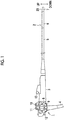
- Fig. 1 is a diagram showing the structure of an endoscope 1 according to the invention.
- the endoscope 1 shown in Fig. 1 includes: an insertion part 2 that is to be inserted into the body of a patient; an operation unit 3 that is connected to the proximal end of the insertion part 2 and is used for the grip of the endoscope 1, the operation of the insertion part 2, and the like; and a universal cord 4 that connects the endoscope 1 to system components, such as a light source device and a processor device (not shown).
- the insertion part 2 includes a soft portion 5, a bendable portion 6, and a distal end portion 7 that are connected in this order from the proximal end toward the distal end.
- the soft portion 5 has flexibility, and is bent along the insertion path of the insertion part 2 in an arbitrary direction.
- the bendable portion 6 is vertically and laterally bent by the operation of angle knobs 8 and 9 of the operation unit 3.
- the distal end portion 7 includes: an observation portion that takes the image of a portion to be observed in the body and sends the taken image to the processor device, which is connected by the universal cord 4, as an observation image (endoscopic image); an illumination portion that irradiates the portion to be observed with illumination light transmitted from the light source device, which is connected by the universal cord 4, through a light guide provided in the endoscope 1; and the like.
- Fig. 2 is an enlarged perspective view of the distal end portion 7.
- the endoscope 1 according to this embodiment is a side-viewing endoscope used as, for example, a duodenoscope and the distal end portion 7 shown in Fig. 2 shows the structure of the side-viewing endoscope.
- the distal end portion 7 is provided with a flat surface 20 substantially parallel to a longitudinal axis that is the axis of the insertion part 2, and the flat surface 20 is provided with an observation window 22 and an illumination window 24.
- a longitudinal axis which is simply mentioned below, means the longitudinal axis of the insertion part 2.
- the observation window 22 is a component of the observation portion that acquires the image of a portion to be observed present on the side with respect to the longitudinal axis (in a radial direction), and allows subject light, which is reflected from the portion to be observed present on the side, to be taken into an optical system (an imaging lens and the like) and imaging means that are other components of the observation portion.
- the illumination window 24 is a component of the illumination portion that is mounted on the distal end portion 7, and irradiates the portion to be observed with illumination light emitted from a light-emitting part which is another component of the illumination portion, that is, a light-emitting part that is provided at a terminal portion of a light guide transmitting light emitted from a light source device.
- a position corresponding to the distal end side of the distal end portion 7 in the direction of the longitudinal axis is referred to as a front side (distal end side), a position opposite to the front side (distal end side) is referred to as a rear side (proximal end side), a position facing the flat surface 20 in a direction perpendicular to the flat surface 20 is referred to as an upper side, a position opposite to the upper side is referred to as a lower side (see Fig. 1 ), and a left side and a right side mean positions corresponding to directions determined on the basis of a positional relationship between the front and the rear and positional relationships between the upper side and the lower side.
- a standing base-receiving slit 38 is provided on the right side of the flat surface 20 in the distal end portion 7, and a standing base 60 is provided in the standing base-receiving slit 38. Since the standing base-receiving slit 38 communicates with a treatment tool inlet 13 (see Fig. 1 ) of the operation unit 3 through a treatment tool-insertion channel inserted into the insertion part 2, a treatment tool inserted from the treatment tool inlet 13 is guided to the standing base-receiving slit 38.
- the standing base 60 bends the traveling direction of the treatment tool guided to the standing base-receiving slit 38 to guide the treatment tool in a direction toward an upper opening portion 38a (referred to as a treatment tool outlet 38a) of the standing base-receiving slit 38, and allows the treatment tool to be led out of the treatment tool outlet 38a.
- a treatment tool outlet 38a an upper opening portion 38a of the standing base-receiving slit 38
- the standing base 60 is allowed to stand or fall (rotated) in a direction where the standing base 60 stands (standing direction) or a direction where the standing base 60 falls (falling direction) by the operation of a standing operation lever 12 (see Fig. 1 ) of the operation unit 3, and changes the lead-out direction (lead-out angle) of the treatment tool to be led out of the treatment tool outlet 38a.
- An air/water supply nozzle (not shown), which can switch the supply of air and the supply of water to the observation window 22 by the operation of an air/water supply button 10 (see Fig. 1 ) of the operation unit 3, is provided near the observation window 22 of the flat surface 20. Further, since a suction channel is connected to the treatment tool-insertion channel in the insertion part 2, suction from the standing base-receiving slit 38 is performed by the operation of a suction button 11 (see Fig. 1 ) of the operation unit 3.
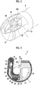
- Fig. 3 is a cross-sectional view of the distal end portion 7 perpendicular to the longitudinal axis
- Fig. 4 is an exploded perspective view of the distal end portion 7.
- the distal end portion 7 includes a distal-end-portion body 30 (see Fig. 4 ) which partitions the inside of the distal end portion 7 into a plurality of regions and to which various components are integrally assembled, and the outer peripheral portion of the distal-end-portion body 30 is covered with a detachable cap 26.
- the cap 26 is made of an elastic material, for example, elastic rubber, and is formed in a shape that has the shape of a cylinder of which the distal end side is closed as a basic shape.
- the cap 26 includes: an opening window 26A that opens the above-mentioned flat surface 20 and the entire upper opening portion 38a (treatment tool outlet 38a) and a part of the upper side of a front opening portion 38b of the standing base-receiving slit 38; and a partition wall portion 26B that closes the entire lower opening portion 38c and a part of the lower side of the front opening portion 38b of the standing base-receiving slit 38.
- an engagement portion (not shown), which protrudes inward in a radial direction in an annular shape, is formed at the proximal end of the cap 26, and the cap 26 is mounted on the distal-end-portion body 30 through the engagement between the engagement portion and a groove 31 formed on the outer peripheral portion of the distal-end-portion body 30.
- the cap 26 is detached at the time of washing as described below.
- the distal-end-portion body 30 is formed of a rigid member that is made of a metal material or the like having corrosion resistance.
- the distal-end-portion body 30 includes a columnar proximal end portion 32 that is close to the proximal end, and a pair of right and left side wall portions 34 and 36 that extends toward the distal end side from the proximal end portion 32 and faces each other.
- the standing base-receiving slit 38 which is a space portion receiving the standing base 60
- a standing lever-receiving chamber 40 which is a space portion receiving a standing lever 82 of a drive member 80 transmitting a driving force to the standing base 60
- an optical-system-receiving chamber 42 which is a space portion receiving components (not shown) of the observation portion and the illumination portion described above, is formed on the left side of the side wall portion 36.
- the standing lever-receiving chamber 40 and the optical-system-receiving chamber 42 are covered with a protective plate not shown in Fig. 4 (see a protective plate 43 of the standing lever-receiving chamber 40 in Fig. 3 ), so that airtightness is kept.
- the standing base-receiving slit 38 includes an upper opening portion as the opening portion 38a (treatment tool outlet 38a), includes a front opening portion as the opening portion 38b, and includes a lower opening portion as the opening portion 38c in a state in which the cap 26 is detached from the distal-end-portion body 30 as shown in Fig. 4 .
- These opening portions 38a, 38b, and 38c are connected to each other, so that the standing base-receiving slit 38 extends from an upper surface to a lower surface through a front surface and is opened.
- a posterior wall portion 46 which is formed by the proximal end portion 32 of the distal-end-portion body 30, is disposed on the proximal end side of the standing base-receiving slit 38, and an opening portion 14a, which is an pipe-line-end portion of the treatment tool-insertion channel 14, is disposed in the posterior wall portion 46 as shown in Fig. 3 .
- the standing base 60 is rotatably installed in the standing base-receiving slit 38 as shown in Fig. 4 .
- the standing base 60 includes a standing base body 62 that includes a guide surface 61 guiding a treatment tool, which is led out of the opening portion 14a of the treatment tool-insertion channel 14, in a direction toward the treatment tool outlet 38a, and a connecting portion 64 that protrudes to the proximal end side from the standing base body 62 and is formed to be narrower than the standing base body 62.
- the connecting portion 64 is provided with a rotating-shaft-receiving portion 66 that is to be fixed to a rotating shaft 81 of the drive member 80.
- the rotating-shaft-receiving portion 66 includes an engagement hole that has a shape and a size substantially corresponding to the shape and the size of an engagement protrusion 90 provided at the distal end of the rotating shaft 81, and the engagement protrusion 90 of the rotating shaft 81 is fitted to the engagement hole as shown in Fig. 7 .
- the engagement protrusion 90 and the engagement hole of the rotating-shaft-receiving portion 66 have a substantially square shape in a cross-section perpendicular to the direction of the axis of the rotating shaft 81.
- the rotating-shaft-receiving portion 66 and the engagement protrusion 90 are fitted to each other, the rotating-shaft-receiving portion 66 and the engagement protrusion 90 of the rotating shaft 81 are engaged with each other not to be rotatable relative to each other. Accordingly, the rotating shaft 81 and the standing base 60 are connected to each other in a state in which the rotating shaft 81 and the standing base 60 are rotated while interlocking with each other.
- a holding hole 58 which passes through the distal-end-portion body from the standing lever-receiving chamber 40 to the standing base-receiving slit 38, is formed near the lower end of the side wall portion 34, which is disposed on the right side of the standing base-receiving slit 38, and the rotating shaft 81 of the drive member 80 is rotatably and pivotally supported by the holding hole 58.
- the rotating shaft 81 is disposed so that the axis of the rotating shaft 81 (rotation axis 81A to be described) is substantially parallel to a lateral direction at a position below the longitudinal axis serving as the center axis of the insertion part 2.
- the rotating shaft 81 is disposed so that the engagement protrusion 90, which is one end portion of the rotating shaft 81, protrudes into the standing base-receiving slit 38, and is connected to the standing base 60 as described above.
- a portion of the side wall portion 34 at which the holding hole 58 is formed protrudes so as to close to the side wall portion 36, and the engagement protrusion 90 of the rotating shaft 81 is disposed so as to protrude at a portion where a gap between the side wall portions 34 and 36 is small.
- the standing lever-receiving chamber 40 which is formed on the right side of the side wall portion 34, is a space portion in which the standing lever 82 of the drive member 80 is received so as to be rotationally movable about the holding hole 58 as shown in Fig. 4 .
- the standing lever 82 and the rotating shaft 81 are integrally formed as the drive member 80 as shown in Figs. 4 , 6 , and 7 and the rotating shaft 81 of the drive member 80 is disposed so as to be inserted into the holding hole 58. Accordingly, the standing lever 82 is disposed so as to be received in the standing lever-receiving chamber 40 as shown in Figs. 3 and 5.
- Fig. 5 is a perspective view showing a state in which the standing base 60 and the drive member 80 are assembled to the distal-end-portion body 30.
- One end portion (proximal end portion) of the standing lever 82 is connected to the rotating shaft 81, and the standing lever 82 extends in a longitudinal shape from one end portion thereof to the other end portion (distal end portion) thereof that is spaced apart from one end portion thereof in a direction perpendicular to the axis of the rotating shaft 81.
- the shape and the like of the standing lever 82 will be described in detail later.
- an operation wire 86 is connected to the distal end portion of the standing lever 82 through a connector 88.
- the operation wire 86 is inserted into the insertion part 2 from a wire insertion hole 44, which is opened to the wall surface of the standing lever-receiving chamber 40, and is connected to the standing operation lever 12 of the operation unit 3.
- the operation wire 86 is pushed and pulled by the operation of the standing operation lever 12, so that the standing lever 82 is rotated together with the rotating shaft 81. Further, the standing base 60 is rotated by the rotation of the rotating shaft 81, so that the standing base 60 is allowed to stand and fall.
- the structure of the rotating shaft 81, which connects the standing lever 82 to the standing base 60, is not limited to this embodiment.
- the standing base 60 may include a first rotating shaft
- the standing lever 82 may include a second rotating shaft
- the first and second rotating shafts may be integrated with each other or connected to each other.
- the rotating shaft 81 of this embodiment corresponds to the first rotating shaft or the second rotating shaft in a case in which the first and second rotating shafts are integrated with each other.
- the rotating shaft 81 of this embodiment corresponds to an aspect in which the first and second rotating shafts are coaxial with each other, but the first and second rotating shafts may not be coaxial with each other.
- the operation wire 86 is one aspect of a transmission member that is provided up to the distal-end-portion body 30 from the operation unit 3 via the insertion part 2 and transmits displacement generated by the operation unit 3 to the standing lever 82, and a mechanism for rotating the standing lever 82 is not limited to this embodiment in which the standing lever 82 is pushed and pulled by the operation wire 86.
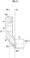
- Fig. 8 is a front view showing only the drive member 80 of the distal end portion 7 (a diagram viewed from the front side of the distal end portion 7)
- Fig. 9 is a side view showing only the drive member 80 of the distal end portion 7 (a diagram viewed from the right side of the distal end portion 7)
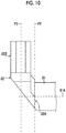
- Fig. 10 is a plan view showing only the drive member 80 of the distal end portion 7 (a diagram viewed from the upper side of the distal end portion 7)
- Fig. 11 is a perspective view showing only the drive member 80 of the distal end portion 7.
- the drive member 80 is composed of the rotating shaft 81 and the standing lever 82 having described above, and the rotating shaft 81 is formed in a columnar shape along the axis 81A. Further, the axis 81A of the rotating shaft 81 is disposed below the longitudinal axis in the distal end portion 7 so as to be substantially parallel to the lateral direction as described above. In the following description, the axis 81A of the rotating shaft 81, that is, an axis serving as the center of rotation of the standing lever 82 (drive member 80) is referred to as the rotation axis 81A.
- the standing lever 82 is formed in a longitudinal shape in which a distal end is bent, and includes a rotating shaft-connection portion 82A which is provided at one end portion (proximal end portion) of the standing lever 82 and to which the rotating shaft 81 corresponding to the second rotating shaft is connected, and a wire-connection portion 82B which is provided at the other end portion (distal end portion) of the standing lever 82 and to which the operation wire 86 corresponding to the transmission member is connected through the above-mentioned connector 88 or the like.
- the rotating shaft-connection portion 82A corresponds to a second rotating shaft-connection portion to which the second rotating shaft is connected
- the wire-connection portion 82B corresponds to a transmission member-connection portion to which the transmission member is connected.
- the standing lever 82 includes a first arm portion 83 that includes the rotating shaft-connection portion 82A, a second arm portion 84 that includes the wire-connection portion 82B, and an arm connection portion 85 that is provided between the first and second arm portions 83 and 84.
- the first arm portion 83 extends to the arm connection portion 85 from an end portion of the rotating shaft 81, and is provided along a first axis 83A extending in a first direction that is different from the direction of the axis 81A of the rotating shaft 81, that is, the rotation axis 81A (see Fig. 8 ).
- the second arm portion 84 extends from the arm connection portion 85, and is provided along a second axis 84A extending in a second direction that is not parallel to a plane including the rotation axis 81A and the first axis 83A.
- a plane which includes the axis 81A of the rotating shaft 81 (rotation axis 81A) and is parallel to the longitudinal axis of the insertion part 2, is referred to as a first plane PI; a plane, which is perpendicular to the rotation axis 81A and crosses the rotating shaft-connection portion 82A, is referred to as a second plane P2; a direction, which obliquely crosses the second plane P2, is referred to as a first direction; and a direction, which includes a component in a direction parallel to the second plane P2 and obliquely crosses the first direction in a case in which the direction is projected onto a first projection plane parallel to the second plane P2, is referred to as a second direction.
- the second direction includes a component in a direction opposite to the direction toward the rotating shaft-connection portion 82A from the arm connection portion 85 in the first projection plane parallel to the second plane P2.
- the second arm portion 84 and the arm connection portion 85 are disposed on a side opposite to one side of the second plane P2 on which the standing base 60 is provided.
- the first arm portion 83 is provided along the first direction from the rotating shaft-connection portion 82A to the arm connection portion 85.
- the second arm portion 84 is provided along the second direction from the arm connection portion 85 to the wire-connection portion 82B.
- the second direction is parallel to the second plane P2.
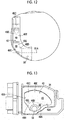
- Fig. 12 is a front view of the standing lever-receiving chamber 40 that is formed in the side wall portion 34 of the distal-end-portion body 30, and Fig. 13 is a side view of the standing lever-receiving chamber 40 that is formed in the side wall portion 34 of the distal-end-portion body 30.
- the standing lever-receiving chamber 40 is formed so as to communicate with the holding hole 58 into which the rotating shaft 81 of the drive member 80 is inserted and dispsoed.
- the standing lever-receiving chamber 40 includes a first arm receiving portion 48 in which the second arm portion 84 is mainly received so as to be rotatable about the axis 81A of the rotating shaft 81 (rotation axis 81A), and a second arm receiving portion 49 in which the first arm portion 83 is mainly received so as to be rotatable about the rotation axis 81A.
- the first arm receiving portion 48 includes a region having the shape of a profile along the shape of a fan having a center at the position of the end portion of the holding hole 58, that is, the position of the proximal end at which the rotating shaft-connection portion 82A of the standing lever 82 received in the standing lever-receiving chamber 40 is disposed.
- the first arm receiving portion 48 includes a distal end-side end surface 48A and a proximal end-side end surface 48B as inner wall surfaces that partition the first arm receiving portion 48, that is, inner wall surfaces of the standing lever-receiving chamber 40 disposed along the positions of the first arm portion 83 in cases in which the standing lever 82 is rotated to the maximum limits of the distal end side (front side) and the proximal end side (rear side) of the distal end portion 7.
- the distal end-side end surface 48A and the proximal end-side end surface 48B are formed along straight lines that are substantially orthogonal to each other.
- the distal end-side end surface 48A and the proximal end-side end surface 48B have an inclination angle of about 45° with respect to a vertical direction on the distal end side and the proximal end side, respectively.
- the inner wall surface, which is formed on one side of the standing lever 82 received in the standing lever-receiving chamber 40 and is close to the standing base 60, of the inner wall surfaces defining the standing lever-receiving chamber 40 is referred to as an inside inner wall surface, and the inner wall surface opposite thereto is referred to as an outside inner wall surface.
- the outside inner wall surface is formed by the protective plate 43 that covers the standing lever-receiving chamber 40 as described above.
- the outer surface, which is formed on one side close to the standing base 60, of outer surfaces, which form the standing lever 82 is referred to as an inside outer surface, and the outer surface opposite thereto is referred to as an outside outer surface.
- the first arm receiving portion 48 includes an inclined surface 48C, which is parallel to the longitudinal axis of the insertion part 2 and obliquely crosses the rotation axis 81A (lateral direction), as the outside inner wall surface of the standing lever-receiving chamber 40.
- the first arm receiving portion 48 includes a conical tapered surface 48D along which the inside outer surface of the first arm portion 83 is formed at the peripheral portion of the end portion of the holding hole 58 as the inside inner wall surface of the standing lever-receiving chamber 40, and includes a vertical surface 48E that is provided near the tapered surface 48D and is substantially perpendicular to the rotation axis 81A.
- the second arm receiving portion 49 includes a region that is further spaced apart from the position of the end portion of the holding hole 58 than the first arm receiving portion 48 and is connected to the first arm receiving portion 48.
- the second arm receiving portion 49 includes an upper inner wall surface 49C of the standing lever-receiving chamber 40 that is an inner wall surface partitioning the second arm receiving portion 49 and is formed in an arc shape, and a distal end-side end surface 49A and a proximal end-side end surface 49B as inner wall surfaces of the standing lever-receiving chamber 40 disposed along the positions of the second arm portion 84 in cases in which the standing lever 82 is rotated to the maximum limits of the distal end side and the proximal end side of the distal end portion 7.
- the distal end-side end surface 49A is connected to the distal end-side end surface 48A of the first arm receiving portion 48, and is formed along a straight line substantially parallel to the longitudinal axis of the insertion part 2.
- the proximal end-side end surface 49B is connected to the proximal end-side end surface 48B of the first arm receiving portion 48, and is formed along a vertical direction.
- the second arm receiving portion 49 includes vertical surfaces 49D and 49E substantially perpendicular to the rotation axis 81A as the outside inner wall surface and the inside inner wall surface of the standing lever-receiving chamber 40.
- the vertical surface 49D is connected to the inclined surface 48C of the first arm receiving portion 48, and the vertical surface 49E is connected to the vertical surface 48E of the first arm receiving portion 48.
- the first arm portion 83 of the standing lever 82 of the drive member 80 extends in the first direction obliquely crossing the second plane P2 perpendicular to the rotation axis 81A as described above. For this reason, as shown in Figs. 3 and 12 , the outside inner wall surface of the first arm receiving portion 48 of the standing lever-receiving chamber 40 can be formed of the inclined surface 48C.
- the standing lever-receiving chamber 40 can be disposed along the curved inner surface of the cap 26, a useless space between the standing lever-receiving chamber 40 (protective plate 43) and the inner surface of the cap 26 can be reduced. Accordingly, since the inner diameter of the cap 26 can be reduced, the diameter of the distal end portion 7 can be reduced.
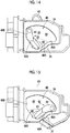
- Figs. 14 and 15 are side views showing the distal-end-portion body 30, to which the standing base 60 and the drive member 80 are assembled, from the right side surface of the distal-end-portion body 30.
- Fig. 14 shows a state in which the standing lever 82 is rotated to the maximum limit on the proximal end side of the distal end portion 7 in the standing lever-receiving chamber 40 (a state in which the standing base 60 is allowed to stand most)
- Fig. 15 shows a state in which the standing lever 82 is rotated to the maximum limit on the distal end side of the distal end portion 7 in the standing lever-receiving chamber 40 (a state in which the standing base 60 is allowed to fall most).
- the first arm portion 83 of the standing lever 82 is in contact with or close to the proximal end-side end surface 48B of the first arm receiving portion 48 and the second arm portion 84 is in contact with or close to the proximal end-side end surface 49B of the second arm receiving portion 49.
- the first arm portion 83 of the standing lever 82 is in contact with or close to the distal end-side end surface 48A of the first arm receiving portion 48 and the second arm portion 84 is in contact with or close to the distal end-side end surface 49A of the second arm receiving portion 49.
- the second arm portion 84 of the standing lever 82 is in contact with the proximal end-side end surface 49B and the distal end-side end surface 49A as shown in Figs. 14 and 15 .
- any one of the first and second arm portions 83 and 84 may be in contact with any one of the proximal end-side end surface 48B and the proximal end-side end surface 49B and any one of the distal end-side end surface 48A and the distal end-side end surface 49A.
- Figs. 16 and 17 are side views showing a standing lever 582 and a standing lever-receiving chamber 540 of a reference form that are to be compared with the standing lever 82 and the standing lever-receiving chamber 40 of this embodiment
- Fig. 16 shows a state in which the standing lever 582 is rotated to the maximum limit on the proximal end side of the distal end portion 7 in the standing lever-receiving chamber 540 (a state in which the standing base 60 is allowed to stand most)
- Fig. 17 shows a state in which the standing lever 582 is rotated to the maximum limit on the distal end side of the distal end portion 7 in the standing lever-receiving chamber 540 (a state in which the standing base 60 is allowed to fall most).
- the standing lever 582 of the reference form shown in Figs. 16 and 17 is formed in the shape of a straight line as a whole in a case in which the standing lever 582 is viewed from the side.
- the standing lever 582 corresponds to an aspect in which the first and second arm portions 83 and 84 are formed along the same direction in a case in which the standing lever 82 is projected onto a plane perpendicular to the rotation axis 81A in this embodiment.
- Components of the distal end portion 7 other than the standing lever 582 and the standing lever-receiving chamber 540 are the same as those of this embodiment, and will be denoted by the same reference numerals as the reference numerals of this embodiment.
- the standing lever-receiving chamber 540 has the shape of a fan, which has a center at the position of the proximal end at which a rotating shaft-connection portion 82A of the standing lever 582 is disposed, as a whole.
- the standing lever-receiving chamber 540 includes a distal end-side end surface 540A and a proximal end-side end surface 540B as inner wall surfaces of the standing lever-receiving chamber 540 that restrict the range of rotation of the standing lever 582 about the rotation axis 81A to the distal end side and the proximal end side of the distal end portion 7.
- the distal end-side end surface 540A and the proximal end-side end surface 540B are formed along straight lines that are substantially orthogonal to each other as in the case of the distal end-side end surface 48A and the proximal end-side end surface 48B of this embodiment.
- the distal end-side end surface 540A and the proximal end-side end surface 540B have an inclination angle of about 45° with respect to a vertical direction on the distal end side and the proximal end side, respectively.
- the rotatable angle of the standing lever 82 is the same as the rotatable angle of the standing lever 582 (about 90°) and the length of the range of the standing lever-receiving chamber 40 in a front-rear direction (the direction of the longitudinal axis of the insertion part 2) substantially corresponds to the length of the range of the standing lever-receiving chamber 540 in the front-rear direction.
- a distance between the rotation axis 81A and a portion of the standing lever 82, which is connected to the operation wire 86, (wire-connection portion 82B) is substantially equal to a distance between the rotation axis 81A and a portion of the standing lever 582, which is connected to the operation wire 86, and the magnitude of an operating force for rotating the standing lever 82 by an operation for pushing and pulling the operation wire 86 is substantially equal to the magnitude of an operating force for rotating the standing lever 582 by an operation for pushing and pulling the operation wire 86.
- the operability of the standing base 60 in this embodiment is substantially the same as the operability of the standing base 60 in the reference form.
- the position of the rotation axis 81A in the front-rear direction in the range of the standing lever-receiving chamber 40 in the front-rear direction in this embodiment is disposed closer to the rear side (proximal end side) than that in the reference form.
- the positions of the observation window 22 and the illumination window 24 of the distal end portion 7 in the front-rear direction are determined on the basis of a positional relationship between the rotation axis 81A and themselves so that a treatment tool led out of the treatment tool outlet 38a through the standing base 60 is displayed in a preferred state in an observation image observed by the observation window 22. For this reason, there is a case where a useless space is formed in a region that is close to the proximal end of the observation window 22 and the illumination window 24 and is closer to the distal end than the proximal end of the standing lever-receiving chamber 40.
- the rotation axis 81A is disposed close to the proximal end in the range of the standing lever-receiving chamber 40 in the front-rear direction as in this embodiment, the useless space can be reduced. Accordingly, the length of the distal end portion 7 in the front-rear direction (the direction of the longitudinal axis of the distal end portion 7) can be shortened.
- the rotation axis 81A can be disposed close to the proximal end side in the range of the standing lever-receiving chamber 540 in the front-rear direction as in this embodiment. Accordingly, the above-mentioned useless space can be reduced.
- the range of a vertical surface 540C substantially orthogonal to the rotation axis 81A on the outside inner wall surface of the standing lever-receiving chamber 540 is widened downward in comparison with the vertical surface 49D (see Fig. 12 ) of this embodiment corresponding to the vertical surface 540C.
- the inner diameter of the cap 26 needs to be increased in the reference form shown in Figs. 16 and 17 , the diameter of the distal end portion 7 is increased.
- the inclination angle of the distal end-side end surface 540A of the standing lever-receiving chamber 540 with respect to the vertical direction needs to be reduced to avoid an increase in the diameter of the distal end portion 7. For this reason, the rotatable angle of the standing lever 582 is reduced.
- the rotation angle of the standing lever 82 can be increased without causing an increase in the diameter of the distal end portion 7.
- the lower portion of the distal end portion of the side wall portion 34 can be formed in a notched shape so as to correspond to the shape of a bent profile, which is formed by the distal end-side end surface 48A and the distal end-side end surface 49A of the standing lever-receiving chamber 40.
- the standing base 60 is allowed to fall most as shown in Fig. 15 , so that a large area of the standing base 60 can be exposed from the standing base-receiving slit 38. Accordingly, an effect of easily washing the standing base 60 is also obtained.
- the second arm portion 84 of the standing lever 82 of the drive member 80 extends from the arm connection portion 85 along the second direction, and the second direction is parallel to the second plane P2 (see Figs. 8 and 9 , and the like).
- the second direction is a direction that includes a component in a direction parallel to the second plane P2 and obliquely crosses the first direction (a direction in which the first arm portion 83 extends) in a case in which the direction is projected onto a first projection plane parallel to the second plane P2, the second direction may not be parallel to the second plane P2.
- the second direction may be a direction that obliquely crosses the second plane P2 and allows the wire-connection portion 82B to be positioned on one side of a third plane P3 opposite to the side on which the rotating shaft-connection portion 82A is provided in a case in which a plane, which crosses the arm connection portion 85 and is parallel to the second plane P2, is referred to as the third plane P3 (see Fig. 10 ).
- an angle between the second direction and the second plane is smaller than an angle between the first direction and the second plane in a case in which the second direction is projected onto a second projection plane perpendicular to the direction of the longitudinal axis of the distal end portion 7.
- the second direction includes a component in a direction opposite to the direction toward the rotating shaft-connection portion 82A from the arm connection portion 85 in the first projection plane parallel to the second plane P2 as in this embodiment.
- the second direction may include a component in a direction toward the distal end side of the distal end portion 7 from the arm connection portion 85 as in this embodiment in a state in which the first direction is a direction perpendicular to the first plane P1 in the first projection plane parallel to the second plane P2.
- the second direction may include a component in a direction toward the proximal end side of the distal end portion 7 from the arm connection portion 85 in a state in which the first direction is a direction perpendicular to the first plane P1 in the first projection plane parallel to the second plane P2. That is, the shape of the standing lever 82 of the drive member 80 and the shape of the standing lever-receiving chamber 40 of this embodiment shown in Fig. 14 may also be horizontally inverted as shown in Fig. 20 .
- this structure is useful in a case in which a useless space is formed in a region that is close to the distal end of the observation window 22 and the illumination window 24 and is closer to the proximal end than the distal end of the standing lever-receiving chamber 40. That is, since the rotation axis 81A is disposed close to the distal end in the range of the standing lever-receiving chamber 40 in the front-rear direction, the useless space can be reduced. Accordingly, the length of the distal end portion 7 in the front-rear direction (the direction of the longitudinal axis of the distal end portion 7) can be shortened.
- the distal end-side end surfaces 48A and 49A and the proximal end-side end surfaces 48B and 49B of the standing lever-receiving chamber 40 are provided as a rotation restricting portion that restricts the range of rotation of the first arm portion 83 (standing lever 82) about the rotation axis 81A.
- the first direction is a direction perpendicular to the first plane P1 (that is, the vertical direction) in the first projection plane parallel to the second plane P2.
- the first direction does not necessarily need to be limited thereto.
- the range of rotation that is, the rotatable angle of the first arm portion 83 (standing lever 82) is about 90° in this embodiment, but is not limited thereto.
- first arm portion 83 of the standing lever 82 of this embodiment is provided along the first direction and the second arm portion 84 is provided along the second direction, but this does not mean that the first and second arm portions 83 and 84 are formed in the shape of a straight line. As long as a straight line, which connects both ends of the first arm portion 83, is along the first direction, the first arm portion 83 may be curved and may be bent at a plurality of positions. The same applies to the second arm portion 84.
Landscapes
- Health & Medical Sciences (AREA)
- Life Sciences & Earth Sciences (AREA)
- Surgery (AREA)
- Physics & Mathematics (AREA)
- Optics & Photonics (AREA)
- Biomedical Technology (AREA)
- General Health & Medical Sciences (AREA)
- Veterinary Medicine (AREA)
- Nuclear Medicine, Radiotherapy & Molecular Imaging (AREA)
- Engineering & Computer Science (AREA)
- Public Health (AREA)
- Heart & Thoracic Surgery (AREA)
- Medical Informatics (AREA)
- Molecular Biology (AREA)
- Animal Behavior & Ethology (AREA)
- Biophysics (AREA)
- Pathology (AREA)
- Radiology & Medical Imaging (AREA)
- Astronomy & Astrophysics (AREA)
- General Physics & Mathematics (AREA)
- Ophthalmology & Optometry (AREA)
- Endoscopes (AREA)
- Instruments For Viewing The Inside Of Hollow Bodies (AREA)
Abstract
Description
- The present invention relates to an endoscope and a treatment tool-standing mechanism (forceps elevating mechanism), and more particularly, to an endoscope and a treatment tool-standing mechanismincluding a treatment tool-standing base (forceps elevator) (hereinafter, referred to as a standing base).
- In a case in which a treatment tool is inserted into in an endoscope, into which various treatment tools can be inserted, from a treatment tool insertion opening provided in an operation unit of the endoscope, the treatment tool is inserted into an insertion part of the endoscope and is led out of a treatment tool outlet that is opened to a distal-end-portion body of the insertion part. For example, a forceps, a snare, a guide wire, an imaging tube, a puncture needle, and the like are used as treatment tools.
- Since the lead-out direction of such a treatment tool needs to be changed in a distal-end-portion body of the endoscope so that treatment is performed at a desired position on a subject, a standing base for changing the lead-out direction of the treatment tool and a drive mechanism for the standing base are provided in the distal-end-portion body of the endoscope as a treatment tool-standing mechanism.
- A mechanism, which allows a standing base to stand and fall by an operation member of an operation unit by a standing lever and an operation wire connected to the standing base, is disclosed in each of
JP2010-253234A JP2002-17663A - According to the treatment tool-standing mechanism disclosed in
JP2010-253234A - Accordingly, in a case in which the operation wire is operated so as to be pushed and pulled by the operation member of the operation unit of the endoscope, the standing lever is rotated about a rotating shaft. Further, since the rotating shaft member and the standing base are also rotated about the rotating shaft while interlocking with the rotation of the standing lever, the standing base is operated to fall between a standing position and a falling position.
- Furthermore,
JP2002-17663A JP2010-253234A - In the treatment tool-standing mechanism using a standing lever that is disclosed in each of
JP2010-253234A JP2002-17663A - The positions of an observation window and an illumination window, which are disposed in the distal-end-portion body of the endoscope, in the direction of the longitudinal axis of the insertion part are determined on the basis of the positions of the standing base and the standing lever in the direction of the longitudinal axis of the rotating shaft so that a treatment tool led out of the treatment tool outlet through the standing base is displayed in a preferred state in an observation image observed by the observation window.
- For this reason, there is a case where a useless space is formed in a region that is close to the proximal end of the observation window and the illumination window and is closer to the distal end than the proximal end of the standing lever-receiving chamber or a region that is close to the distal end of the observation window and the illumination window and is closer to the proximal end than the distal end of the standing lever-receiving chamber.
- Accordingly, if the treatment tool-standing mechanism can be adapted so that the useless space is reduced, the length of the distal-end-portion body of the endoscope in the direction of the longitudinal axis of the distal end portion can be shortened and the size of the distal-end-portion body can be reduced.
- Therefore, for example, in a case in which the above-mentioned useless space is present on the proximal end side of the observation window and the illumination window, there is considered a method of making the range of the rotatable angle of the standing lever be larger on the distal end side than the proximal end side in a direction perpendicular to the longitudinal axis so that the standing lever-receiving chamber is narrow on the proximal end side of the position of the rotating shaft and is wide on the distal end side thereof.
- However, the useless space present on the proximal end side of the observation window and the illumination window can be reduced in this case, but the direction of the standing lever is close to the direction of the longitudinal axis in a state in which the standing lever is rotated to the maximum limit on the distal end side. For this reason, since the inner diameter of the cover member needs to be increased to avoid the interference between the standing lever (standing lever-receiving chamber) and the cover member, an increase in the diameter of the distal-end-portion body is caused.
- Accordingly, the size of the distal-end-portion body cannot be reduced in the above-mentioned method.
- Further, there is also considered a method of reducing the above-mentioned useless space by shortening the length of the standing lever and making the standing lever-receiving chamber small as a whole.
- However, in a case in which the standing lever is made short, a distance between the rotating shaft of the standing lever and a portion of the standing lever, which is connected to the operation wire, is shortened. For this reason, the magnitude of an operating force for rotating the standing lever by an operation for pushing and pulling the operation wire is increased. Accordingly, there is a problem that operability deteriorates.
- Furthermore, as the rotatable angle of the standing base is increased to ensure good operability of the standing base, a useless region present on the proximal end side or the distal end side of the observation window and the illumination window is increased or the direction of the standing lever, which is obtained in a case in which the standing lever is rotated to the maximum limit, is close to the direction of the longitudinal axis as described above. Accordingly, there is a problem that an increase in the size of the distal-end-portion body is caused.
- The invention has been made in consideration of these circumstances, and an object of the invention is to provide an endoscope and a treatment tool-standing mechanism that allows a distal-end-portion body to be reduced in size while ensuring good operability of a standing base.
- In order to achieve the object, an endoscope according to an aspect of the invention comprises: an insertion part that includes a distal end, a proximal end, and a longitudinal axis; a distal-end-portion body that is provided on a distal end side of the insertion part; an operation unit that is provided on a proximal end side of the insertion part; a treatment tool-standing base that is provided in the distal-end-portion body and includes a first rotating shaft; a standing lever that is provided in the distal-end-portion body, includes a second rotating shaft, and allows the treatment tool-standing base to stand and fall; and a transmission member that is provided up to the distal-end-portion body from the operation unit via the insertion part and transmits displacement generated by the operation unit to the standing lever. The standing lever includes a first arm portion that includes a second rotating shaft-connection portion to which the second rotating shaft is connected, a second arm portion that includes a transmission member-connection portion to which the transmission member is connected, and an arm connection portion that is provided between the first and second arm portions. In a case in which a plane, which includes an axis of the second rotating shaft and is parallel to the longitudinal axis, is referred to as a first plane, a plane, which is perpendicular to the axis of the second rotating shaft and crosses the second rotating shaft-connection portion, is referred to as a second plane, a direction, which obliquely crosses the second plane, is referred to as a first direction, and a direction, which includes a component in a direction parallel to the second plane and obliquely crosses the first direction in a case in which the direction is projected onto a first projection plane parallel to the second plane, is referred to as a second direction, the second arm portion and the arm connection portion are disposed on a side opposite to one side of the second plane on which the treatment tool-standing base is provided, the first arm portion is provided along the first direction from the second rotating shaft-connection portion to the arm connection portion, the second arm portion is provided along the second direction from the arm connection portion to the transmission member-connection portion, and the second direction includes a component in a direction opposite to a direction toward the second rotating shaft-connection portion from the arm connection portion in the first projection plane.
- According to this aspect, since the standing lever includes the first arm portion and the second arm portion, the standing lever can be easily disposed so as to correspond to the shape of the outer periphery of the distal-end-portion body in a case in which the standing lever is viewed in the direction of the longitudinal axis of the insertion part of the endoscope. Further, since one space of spaces present on the distal end side and the proximal end side of the distal-end-portion body can be reduced depending on the direction of the second arm portion of the standing lever and the other space can be ensured to be wide, a limited space can be effectively used as a whole without an increase in the size of the distal-end-portion body. Furthermore, a distance between a portion of the standing lever, which is connected to the transmission member, and the center of rotation (second rotating shaft) can be set by the first arm portion and the second arm portion so that the magnitude of an operating force for rotating the standing lever is appropriate. Accordingly, it is possible to reduce the size of the distal-end-portion body while ensuring good operability of the standing base.
- In an endoscope according to another aspect of the invention, the second direction may be a direction parallel to the second plane.
- In another aspect of the invention, the second direction may be a direction obliquely crossing the second plane; in a case in which a plane, which crosses the arm connection portion and is parallel to the second plane, is referred to as a third plane, the transmission member-connection portion may be positioned on a side opposite to one side of the third plane on which the second rotating shaft-connection portion is provided; and an angle between the second direction and the second plane may be smaller than an angle between the first direction and the second plane in a case in which the second direction is projected onto a second projection plane perpendicular to the longitudinal axis.
- In another aspect of the invention, the second direction may include a component in a direction toward a distal end side of the longitudinal axis of the insertion part from the arm connection portion in a state in which the first direction is a direction perpendicular to the first plane in the first projection plane.
- In another aspect of the invention, the second direction may include a component in a direction toward a proximal end side of the longitudinal axis of the insertion part from the arm connection portion in a state in which the first direction is a direction perpendicular to the first plane in the first projection plane.
- In another aspect of the invention, the first and second rotating shafts may be coaxial with each other.
- In another aspect of the invention, the distal-end-portion body may include a rotation restricting portion that restricts the range of rotation of the first arm portion about the axis of the second rotating shaft, and the first direction may be a direction perpendicular to the first plane in the first projection plane in a case in which the first arm portion is positioned at a middle position of the range of rotation.
- In order to achieve the object, a treatment tool-standing mechanism of an endoscope according to another aspect of the invention includes an insertion part that includes a distal end, a proximal end, and a longitudinal axis, a distal-end-portion body that is provided on a distal end side of the insertion part, an operation unit that is provided on a proximal end side of the insertion part, and a treatment tool-standing base that is provided in the distal-end-portion body and includes a first rotating shaft. The treatment tool-standing mechanism comprises: a standing lever that is provided in the distal-end-portion body, includes a second rotating shaft, and allows the treatment tool-standing base to stand and fall; and a transmission member that is provided up to the distal-end-portion body from the operation unit via the insertion part and transmits displacement generated by the operation unit to the standing lever. The standing lever includes a first arm portion that includes a second rotating shaft-connection portion to which the second rotating shaft is connected, a second arm portion that includes a transmission member-connection portion to which the transmission member is connected, and an arm connection portion that is provided between the first and second arm portions. In a case in which a plane, which includes an axis of the second rotating shaft and is parallel to the longitudinal axis, is referred to as a first plane, a plane, which is perpendicular to the axis of the second rotating shaft and crosses the second rotating shaft-connection portion, is referred to as a second plane, a direction, which obliquely crosses the second plane, is referred to as a first direction, and a direction, which includes a component in a direction parallel to the second plane and obliquely crosses the first direction in a case in which the direction is projected onto a first projection plane parallel to the second plane, is referred to as a second direction, the second arm portion and the arm connection portion are disposed on a side opposite to one side of the second plane on which the treatment tool-standing base is provided, the first arm portion is provided along the first direction from the second rotating shaft-connection portion to the arm connection portion, the second arm portion is provided along the second direction from the arm connection portion to the transmission member-connection portion, and the second direction includes a component in a direction opposite to a direction toward the second rotating shaft-connection portion from the arm connection portion in the first projection plane.
- According to the invention, it is possible to reduce the size of the distal-end-portion body while ensuring good operability of the standing base.
-
-
Fig. 1 is a diagram showing the structure of an endoscope according to the invention. -
Fig. 2 is an enlarged perspective view of a distal end portion. -
Fig. 3 is a cross-sectional view of the distal end portion. -
Fig. 4 is an exploded perspective view of the distal end portion. -
Fig. 5 is a perspective view showing a state in which a standing base and a drive member are assembled to a distal-end-portion body. -
Fig. 6 is a perspective view showing the standing base and the drive member. -
Fig. 7 is a perspective view showing the standing base and the drive member. -
Fig. 8 is a front view showing only the drive member of the distal end portion. -
Fig. 9 is a side view showing only the drive member of the distal end portion. -
Fig. 10 is a plan view showing only the drive member of the distal end portion. -
Fig. 11 is a perspective view showing only the drive member of the distal end portion. -
Fig. 12 is a front view of a standing lever-receiving chamber that is formed in a side wall portion of the distal-end-portion body. -
Fig. 13 is a side view of the standing lever-receiving chamber that is formed in the side wall portion of the distal-end-portion body. -
Fig. 14 is a side view showing the state of a standing lever in the standing lever-receiving chamber in a case in which the standing base is allowed to stand most. -
Fig. 15 is a side view showing the state of the standing lever in the standing lever-receiving chamber in a case in which the standing base is allowed to fall most. -
Fig. 16 is a side view showing a standing lever and a standing lever-receiving chamber of a reference form and is a side view showing the state of the standing lever in the standing lever-receiving chamber in a case in which the standing base is allowed to stand most. -
Fig. 17 is a side view showing the standing lever and the standing lever-receiving chamber of the reference form and is a side view showing the state of the standing lever in the standing lever-receiving chamber in a case in which the standing base is allowed to fall most. -
Fig. 18 is a side view showing another form of the standing lever-receiving chamber of the reference form ofFigs. 16 and 17 . -
Fig. 19 is a front view of the standing lever-receiving chamber ofFig. 18 . -
Fig. 20 is a side view showing a standing lever and a standing lever-receiving chamber of another embodiment. - Preferred embodiments of the invention will be described in detail below with reference to the accompanying drawings.
-
Fig. 1 is a diagram showing the structure of anendoscope 1 according to the invention. - The
endoscope 1 shown inFig. 1 includes: aninsertion part 2 that is to be inserted into the body of a patient; anoperation unit 3 that is connected to the proximal end of theinsertion part 2 and is used for the grip of theendoscope 1, the operation of theinsertion part 2, and the like; and a universal cord 4 that connects theendoscope 1 to system components, such as a light source device and a processor device (not shown). - The
insertion part 2 includes asoft portion 5, abendable portion 6, and a distal end portion 7 that are connected in this order from the proximal end toward the distal end. Thesoft portion 5 has flexibility, and is bent along the insertion path of theinsertion part 2 in an arbitrary direction. Thebendable portion 6 is vertically and laterally bent by the operation ofangle knobs operation unit 3. The distal end portion 7 includes: an observation portion that takes the image of a portion to be observed in the body and sends the taken image to the processor device, which is connected by the universal cord 4, as an observation image (endoscopic image); an illumination portion that irradiates the portion to be observed with illumination light transmitted from the light source device, which is connected by the universal cord 4, through a light guide provided in theendoscope 1; and the like. -
Fig. 2 is an enlarged perspective view of the distal end portion 7. Theendoscope 1 according to this embodiment is a side-viewing endoscope used as, for example, a duodenoscope and the distal end portion 7 shown inFig. 2 shows the structure of the side-viewing endoscope. - As shown in
Fig. 2 , the distal end portion 7 is provided with aflat surface 20 substantially parallel to a longitudinal axis that is the axis of theinsertion part 2, and theflat surface 20 is provided with anobservation window 22 and anillumination window 24. A longitudinal axis, which is simply mentioned below, means the longitudinal axis of theinsertion part 2. - The
observation window 22 is a component of the observation portion that acquires the image of a portion to be observed present on the side with respect to the longitudinal axis (in a radial direction), and allows subject light, which is reflected from the portion to be observed present on the side, to be taken into an optical system (an imaging lens and the like) and imaging means that are other components of the observation portion. Theillumination window 24 is a component of the illumination portion that is mounted on the distal end portion 7, and irradiates the portion to be observed with illumination light emitted from a light-emitting part which is another component of the illumination portion, that is, a light-emitting part that is provided at a terminal portion of a light guide transmitting light emitted from a light source device. - A position corresponding to the distal end side of the distal end portion 7 in the direction of the longitudinal axis is referred to as a front side (distal end side), a position opposite to the front side (distal end side) is referred to as a rear side (proximal end side), a position facing the
flat surface 20 in a direction perpendicular to theflat surface 20 is referred to as an upper side, a position opposite to the upper side is referred to as a lower side (seeFig. 1 ), and a left side and a right side mean positions corresponding to directions determined on the basis of a positional relationship between the front and the rear and positional relationships between the upper side and the lower side. - Further, a standing base-receiving
slit 38 is provided on the right side of theflat surface 20 in the distal end portion 7, and a standingbase 60 is provided in the standing base-receivingslit 38. Since the standing base-receivingslit 38 communicates with a treatment tool inlet 13 (seeFig. 1 ) of theoperation unit 3 through a treatment tool-insertion channel inserted into theinsertion part 2, a treatment tool inserted from thetreatment tool inlet 13 is guided to the standing base-receivingslit 38. - The standing
base 60 bends the traveling direction of the treatment tool guided to the standing base-receivingslit 38 to guide the treatment tool in a direction toward anupper opening portion 38a (referred to as atreatment tool outlet 38a) of the standing base-receivingslit 38, and allows the treatment tool to be led out of thetreatment tool outlet 38a. - Further, the standing
base 60 is allowed to stand or fall (rotated) in a direction where the standingbase 60 stands (standing direction) or a direction where the standingbase 60 falls (falling direction) by the operation of a standing operation lever 12 (seeFig. 1 ) of theoperation unit 3, and changes the lead-out direction (lead-out angle) of the treatment tool to be led out of thetreatment tool outlet 38a. - An air/water supply nozzle (not shown), which can switch the supply of air and the supply of water to the
observation window 22 by the operation of an air/water supply button 10 (seeFig. 1 ) of theoperation unit 3, is provided near theobservation window 22 of theflat surface 20. Further, since a suction channel is connected to the treatment tool-insertion channel in theinsertion part 2, suction from the standing base-receivingslit 38 is performed by the operation of a suction button 11 (seeFig. 1 ) of theoperation unit 3. - Subsequently, a treatment tool-standing mechanism (drive mechanism for the standing base 60) of the distal end portion 7 will be described in detail.
-
Fig. 3 is a cross-sectional view of the distal end portion 7 perpendicular to the longitudinal axis, andFig. 4 is an exploded perspective view of the distal end portion 7. - As shown in
Figs. 3 and4 , the distal end portion 7 includes a distal-end-portion body 30 (seeFig. 4 ) which partitions the inside of the distal end portion 7 into a plurality of regions and to which various components are integrally assembled, and the outer peripheral portion of the distal-end-portion body 30 is covered with adetachable cap 26. - The
cap 26 is made of an elastic material, for example, elastic rubber, and is formed in a shape that has the shape of a cylinder of which the distal end side is closed as a basic shape. Thecap 26 includes: an openingwindow 26A that opens the above-mentionedflat surface 20 and the entireupper opening portion 38a (treatment tool outlet 38a) and a part of the upper side of afront opening portion 38b of the standing base-receivingslit 38; and apartition wall portion 26B that closes the entirelower opening portion 38c and a part of the lower side of thefront opening portion 38b of the standing base-receivingslit 38. - Further, an engagement portion (not shown), which protrudes inward in a radial direction in an annular shape, is formed at the proximal end of the
cap 26, and thecap 26 is mounted on the distal-end-portion body 30 through the engagement between the engagement portion and agroove 31 formed on the outer peripheral portion of the distal-end-portion body 30. Thecap 26 is detached at the time of washing as described below. - The distal-end-
portion body 30 is formed of a rigid member that is made of a metal material or the like having corrosion resistance. The distal-end-portion body 30 includes a columnarproximal end portion 32 that is close to the proximal end, and a pair of right and leftside wall portions proximal end portion 32 and faces each other. - Accordingly, in the distal end portion 7, the standing base-receiving
slit 38, which is a space portion receiving the standingbase 60, is formed between the rightside wall portion 34 and the leftside wall portion 36, a standing lever-receivingchamber 40, which is a space portion receiving a standinglever 82 of adrive member 80 transmitting a driving force to the standingbase 60, is formed on the right side of theside wall portion 34, and an optical-system-receivingchamber 42, which is a space portion receiving components (not shown) of the observation portion and the illumination portion described above, is formed on the left side of theside wall portion 36. - The standing lever-receiving
chamber 40 and the optical-system-receivingchamber 42 are covered with a protective plate not shown inFig. 4 (see aprotective plate 43 of the standing lever-receivingchamber 40 inFig. 3 ), so that airtightness is kept. - The standing base-receiving
slit 38 includes an upper opening portion as theopening portion 38a (treatment tool outlet 38a), includes a front opening portion as theopening portion 38b, and includes a lower opening portion as theopening portion 38c in a state in which thecap 26 is detached from the distal-end-portion body 30 as shown inFig. 4 . These openingportions slit 38 extends from an upper surface to a lower surface through a front surface and is opened. - A
posterior wall portion 46, which is formed by theproximal end portion 32 of the distal-end-portion body 30, is disposed on the proximal end side of the standing base-receivingslit 38, and anopening portion 14a, which is an pipe-line-end portion of the treatment tool-insertion channel 14, is disposed in theposterior wall portion 46 as shown inFig. 3 . - The standing
base 60 is rotatably installed in the standing base-receivingslit 38 as shown inFig. 4 . - As shown in an exploded perspective view of
Fig. 6 in which only the standingbase 60 and thedrive member 80 are shown, the standingbase 60 includes a standingbase body 62 that includes aguide surface 61 guiding a treatment tool, which is led out of theopening portion 14a of the treatment tool-insertion channel 14, in a direction toward thetreatment tool outlet 38a, and a connectingportion 64 that protrudes to the proximal end side from the standingbase body 62 and is formed to be narrower than the standingbase body 62. - The connecting
portion 64 is provided with a rotating-shaft-receivingportion 66 that is to be fixed to arotating shaft 81 of thedrive member 80. - The rotating-shaft-receiving
portion 66 includes an engagement hole that has a shape and a size substantially corresponding to the shape and the size of anengagement protrusion 90 provided at the distal end of therotating shaft 81, and theengagement protrusion 90 of therotating shaft 81 is fitted to the engagement hole as shown inFig. 7 . For example, theengagement protrusion 90 and the engagement hole of the rotating-shaft-receivingportion 66 have a substantially square shape in a cross-section perpendicular to the direction of the axis of therotating shaft 81. - Since the engagement hole of the rotating-shaft-receiving
portion 66 and theengagement protrusion 90 are fitted to each other, the rotating-shaft-receivingportion 66 and theengagement protrusion 90 of therotating shaft 81 are engaged with each other not to be rotatable relative to each other. Accordingly, the rotatingshaft 81 and the standingbase 60 are connected to each other in a state in which therotating shaft 81 and the standingbase 60 are rotated while interlocking with each other. - As shown in
Figs. 3 and4 , a holdinghole 58, which passes through the distal-end-portion body from the standing lever-receivingchamber 40 to the standing base-receivingslit 38, is formed near the lower end of theside wall portion 34, which is disposed on the right side of the standing base-receivingslit 38, and therotating shaft 81 of thedrive member 80 is rotatably and pivotally supported by the holdinghole 58. - The rotating
shaft 81 is disposed so that the axis of the rotating shaft 81 (rotation axis 81A to be described) is substantially parallel to a lateral direction at a position below the longitudinal axis serving as the center axis of theinsertion part 2. - Since a
seal member 59 is disposed between therotating shaft 81 and the holdinghole 58 as shown inFig. 3 , the infiltration of gas and liquid into the standing base-receivingslit 38 and the standing lever-receivingchamber 40 is prevented. - Further, the rotating
shaft 81 is disposed so that theengagement protrusion 90, which is one end portion of therotating shaft 81, protrudes into the standing base-receivingslit 38, and is connected to the standingbase 60 as described above. A portion of theside wall portion 34 at which the holdinghole 58 is formed protrudes so as to close to theside wall portion 36, and theengagement protrusion 90 of therotating shaft 81 is disposed so as to protrude at a portion where a gap between theside wall portions - The standing lever-receiving
chamber 40, which is formed on the right side of theside wall portion 34, is a space portion in which the standinglever 82 of thedrive member 80 is received so as to be rotationally movable about the holdinghole 58 as shown inFig. 4 . - In this embodiment, the standing
lever 82 and therotating shaft 81 are integrally formed as thedrive member 80 as shown inFigs. 4 ,6 , and7 and therotating shaft 81 of thedrive member 80 is disposed so as to be inserted into the holdinghole 58. Accordingly, the standinglever 82 is disposed so as to be received in the standing lever-receivingchamber 40 as shown inFigs. 3 and5. Fig. 5 is a perspective view showing a state in which the standingbase 60 and thedrive member 80 are assembled to the distal-end-portion body 30. - One end portion (proximal end portion) of the standing
lever 82 is connected to therotating shaft 81, and the standinglever 82 extends in a longitudinal shape from one end portion thereof to the other end portion (distal end portion) thereof that is spaced apart from one end portion thereof in a direction perpendicular to the axis of therotating shaft 81. The shape and the like of the standinglever 82 will be described in detail later. - As shown in
Fig. 5 , the distal end portion of anoperation wire 86 is connected to the distal end portion of the standinglever 82 through aconnector 88. Theoperation wire 86 is inserted into theinsertion part 2 from awire insertion hole 44, which is opened to the wall surface of the standing lever-receivingchamber 40, and is connected to the standingoperation lever 12 of theoperation unit 3. - Accordingly, the
operation wire 86 is pushed and pulled by the operation of the standingoperation lever 12, so that the standinglever 82 is rotated together with the rotatingshaft 81. Further, the standingbase 60 is rotated by the rotation of therotating shaft 81, so that the standingbase 60 is allowed to stand and fall. - The structure of the
rotating shaft 81, which connects the standinglever 82 to the standingbase 60, is not limited to this embodiment. For example, the standingbase 60 may include a first rotating shaft, the standinglever 82 may include a second rotating shaft, and the first and second rotating shafts may be integrated with each other or connected to each other. The rotatingshaft 81 of this embodiment corresponds to the first rotating shaft or the second rotating shaft in a case in which the first and second rotating shafts are integrated with each other. Further, the rotatingshaft 81 of this embodiment corresponds to an aspect in which the first and second rotating shafts are coaxial with each other, but the first and second rotating shafts may not be coaxial with each other. - Furthermore, the
operation wire 86 is one aspect of a transmission member that is provided up to the distal-end-portion body 30 from theoperation unit 3 via theinsertion part 2 and transmits displacement generated by theoperation unit 3 to the standinglever 82, and a mechanism for rotating the standinglever 82 is not limited to this embodiment in which the standinglever 82 is pushed and pulled by theoperation wire 86. - Subsequently, the shape of the standing
lever 82 of thedrive member 80 and the shape of the standing lever-receivingchamber 40 will be described in detail. -
Fig. 8 is a front view showing only thedrive member 80 of the distal end portion 7 (a diagram viewed from the front side of the distal end portion 7),Fig. 9 is a side view showing only thedrive member 80 of the distal end portion 7 (a diagram viewed from the right side of the distal end portion 7),Fig. 10 is a plan view showing only thedrive member 80 of the distal end portion 7 (a diagram viewed from the upper side of the distal end portion 7), andFig. 11 is a perspective view showing only thedrive member 80 of the distal end portion 7. - As shown in
Figs. 8 ,9 ,10 , and11 , thedrive member 80 is composed of therotating shaft 81 and the standinglever 82 having described above, and therotating shaft 81 is formed in a columnar shape along theaxis 81A. Further, theaxis 81A of therotating shaft 81 is disposed below the longitudinal axis in the distal end portion 7 so as to be substantially parallel to the lateral direction as described above. In the following description, theaxis 81A of therotating shaft 81, that is, an axis serving as the center of rotation of the standing lever 82 (drive member 80) is referred to as therotation axis 81A. - The standing
lever 82 is formed in a longitudinal shape in which a distal end is bent, and includes a rotating shaft-connection portion 82A which is provided at one end portion (proximal end portion) of the standinglever 82 and to which therotating shaft 81 corresponding to the second rotating shaft is connected, and a wire-connection portion 82B which is provided at the other end portion (distal end portion) of the standinglever 82 and to which theoperation wire 86 corresponding to the transmission member is connected through the above-mentionedconnector 88 or the like. The rotating shaft-connection portion 82A corresponds to a second rotating shaft-connection portion to which the second rotating shaft is connected, and the wire-connection portion 82B corresponds to a transmission member-connection portion to which the transmission member is connected. - Further, the standing
lever 82 includes afirst arm portion 83 that includes the rotating shaft-connection portion 82A, asecond arm portion 84 that includes the wire-connection portion 82B, and anarm connection portion 85 that is provided between the first andsecond arm portions - The
first arm portion 83 extends to thearm connection portion 85 from an end portion of therotating shaft 81, and is provided along afirst axis 83A extending in a first direction that is different from the direction of theaxis 81A of therotating shaft 81, that is, therotation axis 81A (seeFig. 8 ). - Further, the
second arm portion 84 extends from thearm connection portion 85, and is provided along asecond axis 84A extending in a second direction that is not parallel to a plane including therotation axis 81A and thefirst axis 83A. - That is, a plane, which includes the
axis 81A of the rotating shaft 81 (rotation axis 81A) and is parallel to the longitudinal axis of theinsertion part 2, is referred to as a first plane PI; a plane, which is perpendicular to therotation axis 81A and crosses the rotating shaft-connection portion 82A, is referred to as a second plane P2; a direction, which obliquely crosses the second plane P2, is referred to as a first direction; and a direction, which includes a component in a direction parallel to the second plane P2 and obliquely crosses the first direction in a case in which the direction is projected onto a first projection plane parallel to the second plane P2, is referred to as a second direction. - Further, the second direction includes a component in a direction opposite to the direction toward the rotating shaft-
connection portion 82A from thearm connection portion 85 in the first projection plane parallel to the second plane P2. - In this case, the
second arm portion 84 and thearm connection portion 85 are disposed on a side opposite to one side of the second plane P2 on which the standingbase 60 is provided. Thefirst arm portion 83 is provided along the first direction from the rotating shaft-connection portion 82A to thearm connection portion 85. Thesecond arm portion 84 is provided along the second direction from thearm connection portion 85 to the wire-connection portion 82B. - In this embodiment, the second direction is parallel to the second plane P2.
-
Fig. 12 is a front view of the standing lever-receivingchamber 40 that is formed in theside wall portion 34 of the distal-end-portion body 30, andFig. 13 is a side view of the standing lever-receivingchamber 40 that is formed in theside wall portion 34 of the distal-end-portion body 30. - As shown in
Figs. 12 and 13 , the standing lever-receivingchamber 40 is formed so as to communicate with the holdinghole 58 into which therotating shaft 81 of thedrive member 80 is inserted and dispsoed. The standing lever-receivingchamber 40 includes a firstarm receiving portion 48 in which thesecond arm portion 84 is mainly received so as to be rotatable about theaxis 81A of the rotating shaft 81 (rotation axis 81A), and a secondarm receiving portion 49 in which thefirst arm portion 83 is mainly received so as to be rotatable about therotation axis 81A. - In a case in which the first
arm receiving portion 48 is viewed from the side of the distal end portion 7 as shown inFig. 13 , the firstarm receiving portion 48 includes a region having the shape of a profile along the shape of a fan having a center at the position of the end portion of the holdinghole 58, that is, the position of the proximal end at which the rotating shaft-connection portion 82A of the standinglever 82 received in the standing lever-receivingchamber 40 is disposed. - The first
arm receiving portion 48 includes a distal end-side end surface 48A and a proximal end-side end surface 48B as inner wall surfaces that partition the firstarm receiving portion 48, that is, inner wall surfaces of the standing lever-receivingchamber 40 disposed along the positions of thefirst arm portion 83 in cases in which the standinglever 82 is rotated to the maximum limits of the distal end side (front side) and the proximal end side (rear side) of the distal end portion 7. - The distal end-
side end surface 48A and the proximal end-side end surface 48B are formed along straight lines that are substantially orthogonal to each other. The distal end-side end surface 48A and the proximal end-side end surface 48B have an inclination angle of about 45° with respect to a vertical direction on the distal end side and the proximal end side, respectively. - Here, the inner wall surface, which is formed on one side of the standing
lever 82 received in the standing lever-receivingchamber 40 and is close to the standingbase 60, of the inner wall surfaces defining the standing lever-receivingchamber 40 is referred to as an inside inner wall surface, and the inner wall surface opposite thereto is referred to as an outside inner wall surface. The outside inner wall surface is formed by theprotective plate 43 that covers the standing lever-receivingchamber 40 as described above. Likewise, the outer surface, which is formed on one side close to the standingbase 60, of outer surfaces, which form the standinglever 82, is referred to as an inside outer surface, and the outer surface opposite thereto is referred to as an outside outer surface. - In a case in which the first
arm receiving portion 48 is viewed from the front side of the distal end portion 7 as shown inFig. 12 , the firstarm receiving portion 48 includes aninclined surface 48C, which is parallel to the longitudinal axis of theinsertion part 2 and obliquely crosses therotation axis 81A (lateral direction), as the outside inner wall surface of the standing lever-receivingchamber 40. - Further, the first
arm receiving portion 48 includes a conical taperedsurface 48D along which the inside outer surface of thefirst arm portion 83 is formed at the peripheral portion of the end portion of the holdinghole 58 as the inside inner wall surface of the standing lever-receivingchamber 40, and includes avertical surface 48E that is provided near the taperedsurface 48D and is substantially perpendicular to therotation axis 81A. - In a case in which the distal end portion 7 is viewed from the side as shown in
Fig. 13 , the secondarm receiving portion 49 includes a region that is further spaced apart from the position of the end portion of the holdinghole 58 than the firstarm receiving portion 48 and is connected to the firstarm receiving portion 48. - Further, the second
arm receiving portion 49 includes an upperinner wall surface 49C of the standing lever-receivingchamber 40 that is an inner wall surface partitioning the secondarm receiving portion 49 and is formed in an arc shape, and a distal end-side end surface 49A and a proximal end-side end surface 49B as inner wall surfaces of the standing lever-receivingchamber 40 disposed along the positions of thesecond arm portion 84 in cases in which the standinglever 82 is rotated to the maximum limits of the distal end side and the proximal end side of the distal end portion 7. - The distal end-
side end surface 49A is connected to the distal end-side end surface 48A of the firstarm receiving portion 48, and is formed along a straight line substantially parallel to the longitudinal axis of theinsertion part 2. - The proximal end-
side end surface 49B is connected to the proximal end-side end surface 48B of the firstarm receiving portion 48, and is formed along a vertical direction. - Further, in a case in which the second
arm receiving portion 49 is viewed from the front side of the distal end portion 7 as shown inFig. 12 , the secondarm receiving portion 49 includesvertical surfaces rotation axis 81A as the outside inner wall surface and the inside inner wall surface of the standing lever-receivingchamber 40. - The
vertical surface 49D is connected to theinclined surface 48C of the firstarm receiving portion 48, and thevertical surface 49E is connected to thevertical surface 48E of the firstarm receiving portion 48. - An action and an effect, which are obtained from the treatment tool-standing mechanism provided in the distal end portion 7 as described above, will be described.
- According to the treatment tool-standing mechanism of this embodiment, the
first arm portion 83 of the standinglever 82 of thedrive member 80 extends in the first direction obliquely crossing the second plane P2 perpendicular to therotation axis 81A as described above. For this reason, as shown inFigs. 3 and12 , the outside inner wall surface of the firstarm receiving portion 48 of the standing lever-receivingchamber 40 can be formed of theinclined surface 48C. - Accordingly, since the standing lever-receiving
chamber 40 can be disposed along the curved inner surface of thecap 26, a useless space between the standing lever-receiving chamber 40 (protective plate 43) and the inner surface of thecap 26 can be reduced. Accordingly, since the inner diameter of thecap 26 can be reduced, the diameter of the distal end portion 7 can be reduced. - Further, according to the treatment tool-standing mechanism of this embodiment, the following action and effect are obtained.
-
Figs. 14 and 15 are side views showing the distal-end-portion body 30, to which the standingbase 60 and thedrive member 80 are assembled, from the right side surface of the distal-end-portion body 30.Fig. 14 shows a state in which the standinglever 82 is rotated to the maximum limit on the proximal end side of the distal end portion 7 in the standing lever-receiving chamber 40 (a state in which the standingbase 60 is allowed to stand most), andFig. 15 shows a state in which the standinglever 82 is rotated to the maximum limit on the distal end side of the distal end portion 7 in the standing lever-receiving chamber 40 (a state in which the standingbase 60 is allowed to fall most). - In a state in which the standing
lever 82 is rotated to the maximum limit on the proximal end side of the distal end portion 7 in the standing lever-receivingchamber 40 as shown inFig. 14 , thefirst arm portion 83 of the standinglever 82 is in contact with or close to the proximal end-side end surface 48B of the firstarm receiving portion 48 and thesecond arm portion 84 is in contact with or close to the proximal end-side end surface 49B of the secondarm receiving portion 49. - Further, in a state in which the standing
lever 82 is rotated to the maximum limit on the distal end side of the distal end portion 7 in the standing lever-receivingchamber 40 as shown inFig. 15 , thefirst arm portion 83 of the standinglever 82 is in contact with or close to the distal end-side end surface 48A of the firstarm receiving portion 48 and thesecond arm portion 84 is in contact with or close to the distal end-side end surface 49A of the secondarm receiving portion 49. - In this embodiment, the
second arm portion 84 of the standinglever 82 is in contact with the proximal end-side end surface 49B and the distal end-side end surface 49A as shown inFigs. 14 and 15 . However, any one of the first andsecond arm portions side end surface 48B and the proximal end-side end surface 49B and any one of the distal end-side end surface 48A and the distal end-side end surface 49A. -
Figs. 16 and 17 are side views showing a standinglever 582 and a standing lever-receivingchamber 540 of a reference form that are to be compared with the standinglever 82 and the standing lever-receivingchamber 40 of this embodiment,Fig. 16 shows a state in which the standinglever 582 is rotated to the maximum limit on the proximal end side of the distal end portion 7 in the standing lever-receiving chamber 540 (a state in which the standingbase 60 is allowed to stand most), andFig. 17 shows a state in which the standinglever 582 is rotated to the maximum limit on the distal end side of the distal end portion 7 in the standing lever-receiving chamber 540 (a state in which the standingbase 60 is allowed to fall most). - In comparison with the standing
lever 82 of this embodiment, the standinglever 582 of the reference form shown inFigs. 16 and 17 is formed in the shape of a straight line as a whole in a case in which the standinglever 582 is viewed from the side. The standinglever 582 corresponds to an aspect in which the first andsecond arm portions lever 82 is projected onto a plane perpendicular to therotation axis 81A in this embodiment. Components of the distal end portion 7 other than the standinglever 582 and the standing lever-receivingchamber 540 are the same as those of this embodiment, and will be denoted by the same reference numerals as the reference numerals of this embodiment. - The standing lever-receiving
chamber 540 has the shape of a fan, which has a center at the position of the proximal end at which a rotating shaft-connection portion 82A of the standinglever 582 is disposed, as a whole. The standing lever-receivingchamber 540 includes a distal end-side end surface 540A and a proximal end-side end surface 540B as inner wall surfaces of the standing lever-receivingchamber 540 that restrict the range of rotation of the standinglever 582 about therotation axis 81A to the distal end side and the proximal end side of the distal end portion 7. - The distal end-
side end surface 540A and the proximal end-side end surface 540B are formed along straight lines that are substantially orthogonal to each other as in the case of the distal end-side end surface 48A and the proximal end-side end surface 48B of this embodiment. The distal end-side end surface 540A and the proximal end-side end surface 540B have an inclination angle of about 45° with respect to a vertical direction on the distal end side and the proximal end side, respectively. - As understood from the comparison between
Figs. 16 and 17 of the reference form andFigs. 14 and 15 of this embodiment, in this embodiment and the reference form, the rotatable angle of the standinglever 82 is the same as the rotatable angle of the standing lever 582 (about 90°) and the length of the range of the standing lever-receivingchamber 40 in a front-rear direction (the direction of the longitudinal axis of the insertion part 2) substantially corresponds to the length of the range of the standing lever-receivingchamber 540 in the front-rear direction. - Further, in this embodiment and the reference form, a distance between the
rotation axis 81A and a portion of the standinglever 82, which is connected to theoperation wire 86, (wire-connection portion 82B) is substantially equal to a distance between therotation axis 81A and a portion of the standinglever 582, which is connected to theoperation wire 86, and the magnitude of an operating force for rotating the standinglever 82 by an operation for pushing and pulling theoperation wire 86 is substantially equal to the magnitude of an operating force for rotating the standinglever 582 by an operation for pushing and pulling theoperation wire 86. Accordingly, the operability of the standingbase 60 in this embodiment is substantially the same as the operability of the standingbase 60 in the reference form. - In contrast, the position of the
rotation axis 81A in the front-rear direction in the range of the standing lever-receivingchamber 40 in the front-rear direction in this embodiment is disposed closer to the rear side (proximal end side) than that in the reference form. - The positions of the
observation window 22 and theillumination window 24 of the distal end portion 7 in the front-rear direction are determined on the basis of a positional relationship between therotation axis 81A and themselves so that a treatment tool led out of thetreatment tool outlet 38a through the standingbase 60 is displayed in a preferred state in an observation image observed by theobservation window 22. For this reason, there is a case where a useless space is formed in a region that is close to the proximal end of theobservation window 22 and theillumination window 24 and is closer to the distal end than the proximal end of the standing lever-receivingchamber 40. - In this case, since the
rotation axis 81A is disposed close to the proximal end in the range of the standing lever-receivingchamber 40 in the front-rear direction as in this embodiment, the useless space can be reduced. Accordingly, the length of the distal end portion 7 in the front-rear direction (the direction of the longitudinal axis of the distal end portion 7) can be shortened. - Further, in a case in which an inclination angle of the distal end-
side end surface 540A with respect to the vertical direction on the distal end side is set to be larger than an inclination angle of the proximal end-side end surface 540B with respect to the vertical direction on the proximal end side as shown inFig. 18 in regard to the standing lever-receivingchamber 540 for the standinglever 582 shown inFigs. 16 and 17 , therotation axis 81A can be disposed close to the proximal end side in the range of the standing lever-receivingchamber 540 in the front-rear direction as in this embodiment. Accordingly, the above-mentioned useless space can be reduced. - However, in this case, as shown in the front view of the standing lever-receiving
chamber 540 ofFig. 19 , the range of avertical surface 540C substantially orthogonal to therotation axis 81A on the outside inner wall surface of the standing lever-receivingchamber 540 is widened downward in comparison with thevertical surface 49D (seeFig. 12 ) of this embodiment corresponding to thevertical surface 540C. For this reason, since the inner diameter of thecap 26 needs to be increased in the reference form shown inFigs. 16 and 17 , the diameter of the distal end portion 7 is increased. - Further, in the reference form shown in
Figs. 16 and 17 , the inclination angle of the distal end-side end surface 540A of the standing lever-receivingchamber 540 with respect to the vertical direction needs to be reduced to avoid an increase in the diameter of the distal end portion 7. For this reason, the rotatable angle of the standinglever 582 is reduced. - That is, according to the treatment tool-standing mechanism of this embodiment, the rotation angle of the standing
lever 82 can be increased without causing an increase in the diameter of the distal end portion 7. - Further, according to the drive of the standing
base 60 of this embodiment, as in the case of anotch portion 35 shown inFigs. 13 to 15 , the lower portion of the distal end portion of theside wall portion 34 can be formed in a notched shape so as to correspond to the shape of a bent profile, which is formed by the distal end-side end surface 48A and the distal end-side end surface 49A of the standing lever-receivingchamber 40. - For this reason, in a case in which the
cap 26 is detached from the distal-end-portion body 30 and the washing of the standingbase 60 and the like are to be performed, the standingbase 60 is allowed to fall most as shown inFig. 15 , so that a large area of the standingbase 60 can be exposed from the standing base-receivingslit 38. Accordingly, an effect of easily washing the standingbase 60 is also obtained. - In the embodiment, the
second arm portion 84 of the standinglever 82 of thedrive member 80 extends from thearm connection portion 85 along the second direction, and the second direction is parallel to the second plane P2 (seeFigs. 8 and9 , and the like). However, as long as the second direction is a direction that includes a component in a direction parallel to the second plane P2 and obliquely crosses the first direction (a direction in which thefirst arm portion 83 extends) in a case in which the direction is projected onto a first projection plane parallel to the second plane P2, the second direction may not be parallel to the second plane P2. - For example, the second direction may be a direction that obliquely crosses the second plane P2 and allows the wire-
connection portion 82B to be positioned on one side of a third plane P3 opposite to the side on which the rotating shaft-connection portion 82A is provided in a case in which a plane, which crosses thearm connection portion 85 and is parallel to the second plane P2, is referred to as the third plane P3 (seeFig. 10 ). - In this case, it is preferable that an angle between the second direction and the second plane is smaller than an angle between the first direction and the second plane in a case in which the second direction is projected onto a second projection plane perpendicular to the direction of the longitudinal axis of the distal end portion 7.
- Further, it is preferable that the second direction includes a component in a direction opposite to the direction toward the rotating shaft-
connection portion 82A from thearm connection portion 85 in the first projection plane parallel to the second plane P2 as in this embodiment. - In this case, the second direction may include a component in a direction toward the distal end side of the distal end portion 7 from the
arm connection portion 85 as in this embodiment in a state in which the first direction is a direction perpendicular to the first plane P1 in the first projection plane parallel to the second plane P2. - Furthermore, unlike in this embodiment, the second direction may include a component in a direction toward the proximal end side of the distal end portion 7 from the
arm connection portion 85 in a state in which the first direction is a direction perpendicular to the first plane P1 in the first projection plane parallel to the second plane P2. That is, the shape of the standinglever 82 of thedrive member 80 and the shape of the standing lever-receivingchamber 40 of this embodiment shown inFig. 14 may also be horizontally inverted as shown inFig. 20 . In this case, this structure is useful in a case in which a useless space is formed in a region that is close to the distal end of theobservation window 22 and theillumination window 24 and is closer to the proximal end than the distal end of the standing lever-receivingchamber 40. That is, since therotation axis 81A is disposed close to the distal end in the range of the standing lever-receivingchamber 40 in the front-rear direction, the useless space can be reduced. Accordingly, the length of the distal end portion 7 in the front-rear direction (the direction of the longitudinal axis of the distal end portion 7) can be shortened. - Further, in this embodiment, the distal end-side end surfaces 48A and 49A and the proximal end-side end surfaces 48B and 49B of the standing lever-receiving
chamber 40 are provided as a rotation restricting portion that restricts the range of rotation of the first arm portion 83 (standing lever 82) about therotation axis 81A. In a case in which these end surfaces are positioned at the middle position of the range of rotation of thefirst arm portion 83, the first direction is a direction perpendicular to the first plane P1 (that is, the vertical direction) in the first projection plane parallel to the second plane P2. However, the first direction does not necessarily need to be limited thereto. - Furthermore, the range of rotation, that is, the rotatable angle of the first arm portion 83 (standing lever 82) is about 90° in this embodiment, but is not limited thereto.
- Moreover, the
first arm portion 83 of the standinglever 82 of this embodiment is provided along the first direction and thesecond arm portion 84 is provided along the second direction, but this does not mean that the first andsecond arm portions first arm portion 83, is along the first direction, thefirst arm portion 83 may be curved and may be bent at a plurality of positions. The same applies to thesecond arm portion 84. -
- 1: endoscope
- 2: insertion part
- 3: operation unit
- 4: universal cord
- 5: soft portion
- 6: bendable portion
- 7: distal end portion
- 12: standing operation lever
- 13: treatment tool inlet
- 20: flat surface
- 22: observation window
- 24: illumination window
- 26: cap
- 30: distal-end-portion body
- 32: proximal end portion
- 34: side wall portion
- 35: notch portion
- 36: side wall portion
- 38: standing base-receiving slit
- 38a: treatment tool outlet
- 40: standing lever-receiving chamber
- 43: protective plate
- 44: wire insertion hole
- 46: posterior wall portion
- 48: first arm receiving portion
- 48A, 49A: distal end-side end surface
- 48B, 49A: proximal end-side end surface
- 48C: inclined surface
- 48D: tapered surface
- 48E, 49D, 49E: vertical surface
- 49: second arm receiving portion
- 58: holding hole
- 60: standing base
- 80: drive member
- 81: rotating shaft
- 81A: rotation axis
- 82: standing lever
- 82A: rotating shaft-connection portion
- 82B: wire-connection portion
- 83: first arm portion
- 83A: first axis
- 84: second arm portion
- 84A: second axis
- 85: arm connection portion
- 86: operation wire
- 88: connector
- 90: engagement protrusion
- P1: first plane
- P2: second plane
- P3: third plane
Claims (8)
- An endoscope comprising:an insertion part that includes a distal end, a proximal end, and a longitudinal axis;a distal-end-portion body that is provided on a distal end side of the insertion part;an operation unit that is provided on a proximal end side of the insertion part;a treatment tool-standing base that is provided in the distal-end-portion body and includes a first rotating shaft;a standing lever that is provided in the distal-end-portion body, includes a second rotating shaft, and allows the treatment tool-standing base to stand and fall; anda transmission member that is provided up to the distal-end-portion body from the operation unit via the insertion part and transmits displacement generated by the operation unit to the standing lever,wherein the standing lever includes a first arm portion that includes a second rotating shaft-connection portion to which the second rotating shaft is connected, a second arm portion that includes a transmission member-connection portion to which the transmission member is connected, and an arm connection portion that is provided between the first and second arm portions, andin a case in which a plane, which includes an axis of the second rotating shaft and is parallel to the longitudinal axis, is referred to as a first plane, a plane, which is perpendicular to the axis of the second rotating shaft and crosses the second rotating shaft-connection portion, is referred to as a second plane, a direction, which obliquely crosses the second plane, is referred to as a first direction, and a direction, which includes a component in a direction parallel to the second plane and obliquely crosses the first direction in a case in which the direction is projected onto a first projection plane parallel to the second plane, is referred to as a second direction, the second arm portion and the arm connection portion are disposed on a side opposite to one side of the second plane on which the treatment tool-standing base is provided, the first arm portion is provided along the first direction from the second rotating shaft-connection portion to the arm connection portion, the second arm portion is provided along the second direction from the arm connection portion to the transmission member-connection portion, and the second direction includes a component in a direction opposite to a direction toward the second rotating shaft-connection portion from the arm connection portion in the first projection plane.
- The endoscope according to claim 1,
wherein the second direction is a direction parallel to the second plane. - The endoscope according to claim 1,wherein the second direction is a direction obliquely crossing the second plane,in a case in which a plane, which crosses the arm connection portion and is parallel to the second plane, is referred to as a third plane, the transmission member-connection portion is positioned on a side opposite to one side of the third plane on which the second rotating shaft-connection portion is provided, andan angle between the second direction and the second plane is smaller than an angle between the first direction and the second plane in a case in which the second direction is projected onto a second projection plane perpendicular to the longitudinal axis.
- The endoscope according to any one of claims 1 to 3,
wherein the second direction includes a component in a direction toward a distal end side of the longitudinal axis of the insertion part from the arm connection portion in a state in which the first direction is a direction perpendicular to the first plane in the first projection plane. - The endoscope according to any one of claims 1 to 3,
wherein the second direction includes a component in a direction toward a proximal end side of the longitudinal axis of the insertion part from the arm connection portion in a state in which the first direction is a direction perpendicular to the first plane in the first projection plane. - The endoscope according to any one of claims 1 to 5,
wherein the first and second rotating shafts are coaxial with each other. - The endoscope according to any one of claims 1 to 6,wherein the distal-end-portion body includes a rotation restricting portion that restricts the range of rotation of the first arm portion about the axis of the second rotating shaft, andthe first direction is a direction perpendicular to the first plane in the first projection plane in a case in which the first arm portion is positioned at a middle position of the range of rotation.
- A treatment tool-standing mechanism of an endoscope including an insertion part that includes a distal end, a proximal end, and a longitudinal axis, a distal-end-portion body that is provided on a distal end side of the insertion part, an operation unit that is provided on a proximal end side of the insertion part, and a treatment tool-standing base that is provided in the distal-end-portion body and includes a first rotating shaft, the treatment tool-standing mechanism comprising:a standing lever that is provided in the distal-end-portion body, includes a second rotating shaft, and allows the treatment tool-standing base to stand and fall; anda transmission member that is provided up to the distal-end-portion body from the operation unit via the insertion part and transmits displacement generated by the operation unit to the standing lever,wherein the standing lever includes a first arm portion that includes a second rotating shaft-connection portion to which the second rotating shaft is connected, a second arm portion that includes a transmission member-connection portion to which the transmission member is connected, and an arm connection portion that is provided between the first and second arm portions, andin a case in which a plane, which includes an axis of the second rotating shaft and is parallel to the longitudinal axis, is referred to as a first plane, a plane, which is perpendicular to the axis of the second rotating shaft and crosses the second rotating shaft-connection portion, is referred to as a second plane, a direction, which obliquely crosses the second plane, is referred to as a first direction, and a direction, which includes a component in a direction parallel to the second plane and obliquely crosses the first direction in a case in which the direction is projected onto a first projection plane parallel to the second plane, is referred to as a second direction, the second arm portion and the arm connection portion are disposed on a side opposite to one side of the second plane on which the treatment tool-standing base is provided, the first arm portion is provided along the first direction from the second rotating shaft-connection portion to the arm connection portion, the second arm portion is provided along the second direction from the arm connection portion to the transmission member-connection portion, and the second direction includes a component in a direction opposite to a direction toward the second rotating shaft-connection portion from the arm connection portion in the first projection plane.
Applications Claiming Priority (2)
| Application Number | Priority Date | Filing Date | Title |
|---|---|---|---|
| JP2015172801 | 2015-09-02 | ||
| PCT/JP2016/074021 WO2017038471A1 (en) | 2015-09-02 | 2016-08-17 | Endoscope and treatment tool erecting mechanism |
Publications (3)
| Publication Number | Publication Date |
|---|---|
| EP3345529A1 true EP3345529A1 (en) | 2018-07-11 |
| EP3345529A4 EP3345529A4 (en) | 2018-08-01 |
| EP3345529B1 EP3345529B1 (en) | 2019-12-18 |
Family
ID=58188818
Family Applications (1)
| Application Number | Title | Priority Date | Filing Date |
|---|---|---|---|
| EP16841503.2A Active EP3345529B1 (en) | 2015-09-02 | 2016-08-17 | Endoscope and treatment tool erecting mechanism |
Country Status (5)
| Country | Link |
|---|---|
| US (1) | US10980558B2 (en) |
| EP (1) | EP3345529B1 (en) |
| JP (1) | JP6542374B2 (en) |
| CN (1) | CN107920724B (en) |
| WO (1) | WO2017038471A1 (en) |
Families Citing this family (9)
| Publication number | Priority date | Publication date | Assignee | Title |
|---|---|---|---|---|
| CN107847220B (en) | 2016-07-11 | 2020-12-04 | Hoya株式会社 | Endoscope with a detachable handle |
| DE102016122477A1 (en) * | 2016-11-22 | 2018-05-24 | Digital Endoscopy Gmbh | ENDOSCOPIC HEAD AND ENDOSCOPE WITH THIS |
| WO2018101465A1 (en) * | 2016-12-02 | 2018-06-07 | オリンパス株式会社 | Distal end cover for endoscope |
| US10914578B2 (en) * | 2016-12-16 | 2021-02-09 | Universität Basel | Apparatus and method for determining the orientation and position of two rigid bodies |
| CA3053400A1 (en) | 2017-03-03 | 2018-09-07 | Boston Scientific Scimed, Inc. | Device tip |
| WO2019150603A1 (en) * | 2018-01-31 | 2019-08-08 | オリンパス株式会社 | Insertion device |
| JP6871431B2 (en) * | 2018-01-31 | 2021-05-12 | オリンパス株式会社 | Cleaning tool for inserters |
| JP7022610B2 (en) * | 2018-02-05 | 2022-02-18 | オリンパス株式会社 | Endoscope |
| JP7033188B2 (en) * | 2018-02-23 | 2022-03-09 | 富士フイルム株式会社 | Endoscope |
Family Cites Families (12)
| Publication number | Priority date | Publication date | Assignee | Title |
|---|---|---|---|---|
| US5569157A (en) * | 1993-05-07 | 1996-10-29 | Olympus Optical Co., Ltd. | Endoscope |
| JP3527561B2 (en) * | 1994-06-13 | 2004-05-17 | ペンタックス株式会社 | Endoscope |
| JP3689320B2 (en) | 2000-07-12 | 2005-08-31 | ペンタックス株式会社 | Endoscope having treatment tool raising device |
| US6582357B2 (en) * | 2000-05-24 | 2003-06-24 | Pentax Corporation | Treating instrument erecting device for use in endoscope |
| JP4163438B2 (en) * | 2002-04-17 | 2008-10-08 | オリンパス株式会社 | Endoscope |
| JP2005304586A (en) * | 2004-04-19 | 2005-11-04 | Pentax Corp | Distal end portion of side viewing type endoscope |
| CN100515319C (en) * | 2006-05-17 | 2009-07-22 | 奥林巴斯医疗株式会社 | Endoscope |
| JP5313068B2 (en) * | 2009-03-09 | 2013-10-09 | 富士フイルム株式会社 | Endoscopic endoscope device |
| JP5678239B2 (en) * | 2012-09-05 | 2015-02-25 | オリンパスメディカルシステムズ株式会社 | Ultrasound endoscope |
| JP5683614B2 (en) * | 2013-01-08 | 2015-03-11 | 富士フイルム株式会社 | Ultrasound endoscope |
| WO2016021231A1 (en) * | 2014-08-05 | 2016-02-11 | オリンパス株式会社 | Endoscope |
| CN107920720B (en) * | 2015-07-30 | 2020-03-06 | 奥林巴斯株式会社 | Endoscope with a detachable handle |
-
2016
- 2016-08-17 WO PCT/JP2016/074021 patent/WO2017038471A1/en active Application Filing
- 2016-08-17 CN CN201680049753.9A patent/CN107920724B/en active Active
- 2016-08-17 EP EP16841503.2A patent/EP3345529B1/en active Active
- 2016-08-17 JP JP2017537727A patent/JP6542374B2/en active Active
-
2018
- 2018-03-01 US US15/908,811 patent/US10980558B2/en active Active
Also Published As
| Publication number | Publication date |
|---|---|
| CN107920724A (en) | 2018-04-17 |
| JP6542374B2 (en) | 2019-07-10 |
| JPWO2017038471A1 (en) | 2018-07-12 |
| US20180185045A1 (en) | 2018-07-05 |
| CN107920724B (en) | 2019-12-03 |
| WO2017038471A1 (en) | 2017-03-09 |
| EP3345529A4 (en) | 2018-08-01 |
| EP3345529B1 (en) | 2019-12-18 |
| US10980558B2 (en) | 2021-04-20 |
Similar Documents
| Publication | Publication Date | Title |
|---|---|---|
| EP3345529B1 (en) | Endoscope and treatment tool erecting mechanism | |
| US12053155B2 (en) | Elevator for directing medical tool | |
| US10010242B2 (en) | Endoscope | |
| US10028642B2 (en) | Endoscope | |
| US20160270635A1 (en) | Endoscope | |
| US20150031947A1 (en) | Endoscope | |
| US11998170B2 (en) | Endoscope | |
| JP6346941B2 (en) | Endoscopic surgical apparatus and mantle tube | |
| JP2010201020A (en) | Side viewing endoscope apparatus | |
| US20220233057A1 (en) | Bending operation mechanism for endoscope, and endoscope | |
| JP7216183B2 (en) | Endoscope | |
| US10398291B2 (en) | Endoscopic surgical device and overtube | |
| JP5078260B2 (en) | Body cavity inspection device | |
| JP7145982B2 (en) | Endoscope | |
| US11696737B2 (en) | Ultrasonic endoscope including treatment-tool erecting base for erecting treatment tool that is led out from opening formed in distal end rigid portion of endoscope insertion section | |
| JP7246539B2 (en) | Endoscope | |
| US20230363624A1 (en) | Endoscope | |
| JP6091252B2 (en) | Endoscope | |
| JP2003339633A (en) | Endoscope | |
| JP6430615B2 (en) | Endoscope |
Legal Events
| Date | Code | Title | Description |
|---|---|---|---|
| STAA | Information on the status of an ep patent application or granted ep patent |
Free format text: STATUS: THE INTERNATIONAL PUBLICATION HAS BEEN MADE |
|
| PUAI | Public reference made under article 153(3) epc to a published international application that has entered the european phase |
Free format text: ORIGINAL CODE: 0009012 |
|
| STAA | Information on the status of an ep patent application or granted ep patent |
Free format text: STATUS: REQUEST FOR EXAMINATION WAS MADE |
|
| 17P | Request for examination filed |
Effective date: 20180226 |
|
| AK | Designated contracting states |
Kind code of ref document: A1 Designated state(s): AL AT BE BG CH CY CZ DE DK EE ES FI FR GB GR HR HU IE IS IT LI LT LU LV MC MK MT NL NO PL PT RO RS SE SI SK SM TR |
|
| AX | Request for extension of the european patent |
Extension state: BA ME |
|
| A4 | Supplementary search report drawn up and despatched |
Effective date: 20180703 |
|
| RIC1 | Information provided on ipc code assigned before grant |
Ipc: A61B 1/00 20060101AFI20180627BHEP Ipc: G02B 23/24 20060101ALI20180627BHEP |
|
| DAV | Request for validation of the european patent (deleted) | ||
| DAX | Request for extension of the european patent (deleted) | ||
| GRAP | Despatch of communication of intention to grant a patent |
Free format text: ORIGINAL CODE: EPIDOSNIGR1 |
|
| STAA | Information on the status of an ep patent application or granted ep patent |
Free format text: STATUS: GRANT OF PATENT IS INTENDED |
|
| INTG | Intention to grant announced |
Effective date: 20190301 |
|
| GRAJ | Information related to disapproval of communication of intention to grant by the applicant or resumption of examination proceedings by the epo deleted |
Free format text: ORIGINAL CODE: EPIDOSDIGR1 |
|
| STAA | Information on the status of an ep patent application or granted ep patent |
Free format text: STATUS: REQUEST FOR EXAMINATION WAS MADE |
|
| GRAP | Despatch of communication of intention to grant a patent |
Free format text: ORIGINAL CODE: EPIDOSNIGR1 |
|
| STAA | Information on the status of an ep patent application or granted ep patent |
Free format text: STATUS: GRANT OF PATENT IS INTENDED |
|
| INTC | Intention to grant announced (deleted) | ||
| INTG | Intention to grant announced |
Effective date: 20190603 |
|
| GRAJ | Information related to disapproval of communication of intention to grant by the applicant or resumption of examination proceedings by the epo deleted |
Free format text: ORIGINAL CODE: EPIDOSDIGR1 |
|
| STAA | Information on the status of an ep patent application or granted ep patent |
Free format text: STATUS: REQUEST FOR EXAMINATION WAS MADE |
|
| GRAP | Despatch of communication of intention to grant a patent |
Free format text: ORIGINAL CODE: EPIDOSNIGR1 |
|
| STAA | Information on the status of an ep patent application or granted ep patent |
Free format text: STATUS: GRANT OF PATENT IS INTENDED |
|
| GRAS | Grant fee paid |
Free format text: ORIGINAL CODE: EPIDOSNIGR3 |
|
| INTG | Intention to grant announced |
Effective date: 20191018 |
|
| GRAA | (expected) grant |
Free format text: ORIGINAL CODE: 0009210 |
|
| STAA | Information on the status of an ep patent application or granted ep patent |
Free format text: STATUS: THE PATENT HAS BEEN GRANTED |
|
| AK | Designated contracting states |
Kind code of ref document: B1 Designated state(s): AL AT BE BG CH CY CZ DE DK EE ES FI FR GB GR HR HU IE IS IT LI LT LU LV MC MK MT NL NO PL PT RO RS SE SI SK SM TR |
|
| REG | Reference to a national code |
Ref country code: CH Ref legal event code: EP |
|
| REG | Reference to a national code |
Ref country code: IE Ref legal event code: FG4D |
|
| REG | Reference to a national code |
Ref country code: DE Ref legal event code: R096 Ref document number: 602016026619 Country of ref document: DE |
|
| REG | Reference to a national code |
Ref country code: AT Ref legal event code: REF Ref document number: 1213657 Country of ref document: AT Kind code of ref document: T Effective date: 20200115 |
|
| REG | Reference to a national code |
Ref country code: NL Ref legal event code: MP Effective date: 20191218 |
|
| PG25 | Lapsed in a contracting state [announced via postgrant information from national office to epo] |
Ref country code: SE Free format text: LAPSE BECAUSE OF FAILURE TO SUBMIT A TRANSLATION OF THE DESCRIPTION OR TO PAY THE FEE WITHIN THE PRESCRIBED TIME-LIMIT Effective date: 20191218 Ref country code: LV Free format text: LAPSE BECAUSE OF FAILURE TO SUBMIT A TRANSLATION OF THE DESCRIPTION OR TO PAY THE FEE WITHIN THE PRESCRIBED TIME-LIMIT Effective date: 20191218 Ref country code: LT Free format text: LAPSE BECAUSE OF FAILURE TO SUBMIT A TRANSLATION OF THE DESCRIPTION OR TO PAY THE FEE WITHIN THE PRESCRIBED TIME-LIMIT Effective date: 20191218 Ref country code: GR Free format text: LAPSE BECAUSE OF FAILURE TO SUBMIT A TRANSLATION OF THE DESCRIPTION OR TO PAY THE FEE WITHIN THE PRESCRIBED TIME-LIMIT Effective date: 20200319 Ref country code: NO Free format text: LAPSE BECAUSE OF FAILURE TO SUBMIT A TRANSLATION OF THE DESCRIPTION OR TO PAY THE FEE WITHIN THE PRESCRIBED TIME-LIMIT Effective date: 20200318 Ref country code: FI Free format text: LAPSE BECAUSE OF FAILURE TO SUBMIT A TRANSLATION OF THE DESCRIPTION OR TO PAY THE FEE WITHIN THE PRESCRIBED TIME-LIMIT Effective date: 20191218 Ref country code: BG Free format text: LAPSE BECAUSE OF FAILURE TO SUBMIT A TRANSLATION OF THE DESCRIPTION OR TO PAY THE FEE WITHIN THE PRESCRIBED TIME-LIMIT Effective date: 20200318 |
|
| REG | Reference to a national code |
Ref country code: LT Ref legal event code: MG4D |
|
| PG25 | Lapsed in a contracting state [announced via postgrant information from national office to epo] |
Ref country code: HR Free format text: LAPSE BECAUSE OF FAILURE TO SUBMIT A TRANSLATION OF THE DESCRIPTION OR TO PAY THE FEE WITHIN THE PRESCRIBED TIME-LIMIT Effective date: 20191218 Ref country code: RS Free format text: LAPSE BECAUSE OF FAILURE TO SUBMIT A TRANSLATION OF THE DESCRIPTION OR TO PAY THE FEE WITHIN THE PRESCRIBED TIME-LIMIT Effective date: 20191218 |
|
| PG25 | Lapsed in a contracting state [announced via postgrant information from national office to epo] |
Ref country code: AL Free format text: LAPSE BECAUSE OF FAILURE TO SUBMIT A TRANSLATION OF THE DESCRIPTION OR TO PAY THE FEE WITHIN THE PRESCRIBED TIME-LIMIT Effective date: 20191218 |
|
| PG25 | Lapsed in a contracting state [announced via postgrant information from national office to epo] |
Ref country code: RO Free format text: LAPSE BECAUSE OF FAILURE TO SUBMIT A TRANSLATION OF THE DESCRIPTION OR TO PAY THE FEE WITHIN THE PRESCRIBED TIME-LIMIT Effective date: 20191218 Ref country code: CZ Free format text: LAPSE BECAUSE OF FAILURE TO SUBMIT A TRANSLATION OF THE DESCRIPTION OR TO PAY THE FEE WITHIN THE PRESCRIBED TIME-LIMIT Effective date: 20191218 Ref country code: NL Free format text: LAPSE BECAUSE OF FAILURE TO SUBMIT A TRANSLATION OF THE DESCRIPTION OR TO PAY THE FEE WITHIN THE PRESCRIBED TIME-LIMIT Effective date: 20191218 Ref country code: PT Free format text: LAPSE BECAUSE OF FAILURE TO SUBMIT A TRANSLATION OF THE DESCRIPTION OR TO PAY THE FEE WITHIN THE PRESCRIBED TIME-LIMIT Effective date: 20200513 Ref country code: EE Free format text: LAPSE BECAUSE OF FAILURE TO SUBMIT A TRANSLATION OF THE DESCRIPTION OR TO PAY THE FEE WITHIN THE PRESCRIBED TIME-LIMIT Effective date: 20191218 |
|
| PG25 | Lapsed in a contracting state [announced via postgrant information from national office to epo] |
Ref country code: SK Free format text: LAPSE BECAUSE OF FAILURE TO SUBMIT A TRANSLATION OF THE DESCRIPTION OR TO PAY THE FEE WITHIN THE PRESCRIBED TIME-LIMIT Effective date: 20191218 Ref country code: IS Free format text: LAPSE BECAUSE OF FAILURE TO SUBMIT A TRANSLATION OF THE DESCRIPTION OR TO PAY THE FEE WITHIN THE PRESCRIBED TIME-LIMIT Effective date: 20200418 Ref country code: SM Free format text: LAPSE BECAUSE OF FAILURE TO SUBMIT A TRANSLATION OF THE DESCRIPTION OR TO PAY THE FEE WITHIN THE PRESCRIBED TIME-LIMIT Effective date: 20191218 |
|
| REG | Reference to a national code |
Ref country code: DE Ref legal event code: R097 Ref document number: 602016026619 Country of ref document: DE |
|
| REG | Reference to a national code |
Ref country code: AT Ref legal event code: MK05 Ref document number: 1213657 Country of ref document: AT Kind code of ref document: T Effective date: 20191218 |
|
| PLBE | No opposition filed within time limit |
Free format text: ORIGINAL CODE: 0009261 |
|
| STAA | Information on the status of an ep patent application or granted ep patent |
Free format text: STATUS: NO OPPOSITION FILED WITHIN TIME LIMIT |
|
| PG25 | Lapsed in a contracting state [announced via postgrant information from national office to epo] |
Ref country code: ES Free format text: LAPSE BECAUSE OF FAILURE TO SUBMIT A TRANSLATION OF THE DESCRIPTION OR TO PAY THE FEE WITHIN THE PRESCRIBED TIME-LIMIT Effective date: 20191218 Ref country code: DK Free format text: LAPSE BECAUSE OF FAILURE TO SUBMIT A TRANSLATION OF THE DESCRIPTION OR TO PAY THE FEE WITHIN THE PRESCRIBED TIME-LIMIT Effective date: 20191218 |
|
| PGFP | Annual fee paid to national office [announced via postgrant information from national office to epo] |
Ref country code: GB Payment date: 20200818 Year of fee payment: 5 Ref country code: FR Payment date: 20200715 Year of fee payment: 5 |
|
| 26N | No opposition filed |
Effective date: 20200921 |
|
| PG25 | Lapsed in a contracting state [announced via postgrant information from national office to epo] |
Ref country code: SI Free format text: LAPSE BECAUSE OF FAILURE TO SUBMIT A TRANSLATION OF THE DESCRIPTION OR TO PAY THE FEE WITHIN THE PRESCRIBED TIME-LIMIT Effective date: 20191218 Ref country code: AT Free format text: LAPSE BECAUSE OF FAILURE TO SUBMIT A TRANSLATION OF THE DESCRIPTION OR TO PAY THE FEE WITHIN THE PRESCRIBED TIME-LIMIT Effective date: 20191218 |
|
| PG25 | Lapsed in a contracting state [announced via postgrant information from national office to epo] |
Ref country code: IT Free format text: LAPSE BECAUSE OF FAILURE TO SUBMIT A TRANSLATION OF THE DESCRIPTION OR TO PAY THE FEE WITHIN THE PRESCRIBED TIME-LIMIT Effective date: 20191218 |
|
| PG25 | Lapsed in a contracting state [announced via postgrant information from national office to epo] |
Ref country code: PL Free format text: LAPSE BECAUSE OF FAILURE TO SUBMIT A TRANSLATION OF THE DESCRIPTION OR TO PAY THE FEE WITHIN THE PRESCRIBED TIME-LIMIT Effective date: 20191218 |
|
| PG25 | Lapsed in a contracting state [announced via postgrant information from national office to epo] |
Ref country code: MC Free format text: LAPSE BECAUSE OF FAILURE TO SUBMIT A TRANSLATION OF THE DESCRIPTION OR TO PAY THE FEE WITHIN THE PRESCRIBED TIME-LIMIT Effective date: 20191218 |
|
| REG | Reference to a national code |
Ref country code: CH Ref legal event code: PL |
|
| PG25 | Lapsed in a contracting state [announced via postgrant information from national office to epo] |
Ref country code: CH Free format text: LAPSE BECAUSE OF NON-PAYMENT OF DUE FEES Effective date: 20200831 Ref country code: LI Free format text: LAPSE BECAUSE OF NON-PAYMENT OF DUE FEES Effective date: 20200831 Ref country code: LU Free format text: LAPSE BECAUSE OF NON-PAYMENT OF DUE FEES Effective date: 20200817 |
|
| REG | Reference to a national code |
Ref country code: BE Ref legal event code: MM Effective date: 20200831 |
|
| PG25 | Lapsed in a contracting state [announced via postgrant information from national office to epo] |
Ref country code: IE Free format text: LAPSE BECAUSE OF NON-PAYMENT OF DUE FEES Effective date: 20200817 Ref country code: BE Free format text: LAPSE BECAUSE OF NON-PAYMENT OF DUE FEES Effective date: 20200831 |
|
| GBPC | Gb: european patent ceased through non-payment of renewal fee |
Effective date: 20210817 |
|
| PG25 | Lapsed in a contracting state [announced via postgrant information from national office to epo] |
Ref country code: TR Free format text: LAPSE BECAUSE OF FAILURE TO SUBMIT A TRANSLATION OF THE DESCRIPTION OR TO PAY THE FEE WITHIN THE PRESCRIBED TIME-LIMIT Effective date: 20191218 Ref country code: MT Free format text: LAPSE BECAUSE OF FAILURE TO SUBMIT A TRANSLATION OF THE DESCRIPTION OR TO PAY THE FEE WITHIN THE PRESCRIBED TIME-LIMIT Effective date: 20191218 Ref country code: CY Free format text: LAPSE BECAUSE OF FAILURE TO SUBMIT A TRANSLATION OF THE DESCRIPTION OR TO PAY THE FEE WITHIN THE PRESCRIBED TIME-LIMIT Effective date: 20191218 |
|
| PG25 | Lapsed in a contracting state [announced via postgrant information from national office to epo] |
Ref country code: MK Free format text: LAPSE BECAUSE OF FAILURE TO SUBMIT A TRANSLATION OF THE DESCRIPTION OR TO PAY THE FEE WITHIN THE PRESCRIBED TIME-LIMIT Effective date: 20191218 |
|
| PG25 | Lapsed in a contracting state [announced via postgrant information from national office to epo] |
Ref country code: GB Free format text: LAPSE BECAUSE OF NON-PAYMENT OF DUE FEES Effective date: 20210817 Ref country code: FR Free format text: LAPSE BECAUSE OF NON-PAYMENT OF DUE FEES Effective date: 20210831 |
|
| P01 | Opt-out of the competence of the unified patent court (upc) registered |
Effective date: 20230515 |
|
| PGFP | Annual fee paid to national office [announced via postgrant information from national office to epo] |
Ref country code: DE Payment date: 20230627 Year of fee payment: 8 |