EP3345331B1 - One-segment pucch formats - Google Patents
One-segment pucch formats Download PDFInfo
- Publication number
- EP3345331B1 EP3345331B1 EP17755292.4A EP17755292A EP3345331B1 EP 3345331 B1 EP3345331 B1 EP 3345331B1 EP 17755292 A EP17755292 A EP 17755292A EP 3345331 B1 EP3345331 B1 EP 3345331B1
- Authority
- EP
- European Patent Office
- Prior art keywords
- segment
- format
- transmission
- subframe format
- subframe
- Prior art date
- Legal status (The legal status is an assumption and is not a legal conclusion. Google has not performed a legal analysis and makes no representation as to the accuracy of the status listed.)
- Active
Links
- 230000005540 biological transmission Effects 0.000 claims description 74
- 238000000034 method Methods 0.000 claims description 40
- 238000012545 processing Methods 0.000 claims description 19
- 238000004590 computer program Methods 0.000 claims description 11
- 230000008054 signal transmission Effects 0.000 claims description 9
- 230000004044 response Effects 0.000 claims description 3
- 238000004891 communication Methods 0.000 description 23
- 230000011664 signaling Effects 0.000 description 16
- 230000002776 aggregation Effects 0.000 description 8
- 238000004220 aggregation Methods 0.000 description 8
- 239000000969 carrier Substances 0.000 description 8
- 238000010586 diagram Methods 0.000 description 7
- 238000001228 spectrum Methods 0.000 description 4
- 101100411667 Arabidopsis thaliana RAN4 gene Proteins 0.000 description 3
- 101000741965 Homo sapiens Inactive tyrosine-protein kinase PRAG1 Proteins 0.000 description 3
- 102100038659 Inactive tyrosine-protein kinase PRAG1 Human genes 0.000 description 3
- 239000013256 coordination polymer Substances 0.000 description 3
- 230000001419 dependent effect Effects 0.000 description 3
- 238000005516 engineering process Methods 0.000 description 3
- 238000012544 monitoring process Methods 0.000 description 3
- 230000001934 delay Effects 0.000 description 2
- 230000003111 delayed effect Effects 0.000 description 2
- 230000006870 function Effects 0.000 description 2
- 238000005259 measurement Methods 0.000 description 2
- 230000010363 phase shift Effects 0.000 description 2
- 230000007480 spreading Effects 0.000 description 2
- 238000003892 spreading Methods 0.000 description 2
- 238000003860 storage Methods 0.000 description 2
- 101150071746 Pbsn gene Proteins 0.000 description 1
- 101150069124 RAN1 gene Proteins 0.000 description 1
- 101100355633 Salmo salar ran gene Proteins 0.000 description 1
- 230000004931 aggregating effect Effects 0.000 description 1
- 230000006399 behavior Effects 0.000 description 1
- 238000004364 calculation method Methods 0.000 description 1
- 125000004122 cyclic group Chemical group 0.000 description 1
- 230000003247 decreasing effect Effects 0.000 description 1
- 230000014509 gene expression Effects 0.000 description 1
- 230000006872 improvement Effects 0.000 description 1
- 230000002045 lasting effect Effects 0.000 description 1
- 230000007774 longterm Effects 0.000 description 1
- 238000007726 management method Methods 0.000 description 1
- 230000007246 mechanism Effects 0.000 description 1
- 230000003287 optical effect Effects 0.000 description 1
- 229920001690 polydopamine Polymers 0.000 description 1
- 230000008569 process Effects 0.000 description 1
- 238000013468 resource allocation Methods 0.000 description 1
- 230000000717 retained effect Effects 0.000 description 1
- 238000004904 shortening Methods 0.000 description 1
- 238000012546 transfer Methods 0.000 description 1
- 230000007704 transition Effects 0.000 description 1
- 238000012384 transportation and delivery Methods 0.000 description 1
Images

Classifications
-
- H—ELECTRICITY
- H04—ELECTRIC COMMUNICATION TECHNIQUE
- H04W—WIRELESS COMMUNICATION NETWORKS
- H04W72/00—Local resource management
-
- H—ELECTRICITY
- H04—ELECTRIC COMMUNICATION TECHNIQUE
- H04L—TRANSMISSION OF DIGITAL INFORMATION, e.g. TELEGRAPHIC COMMUNICATION
- H04L5/00—Arrangements affording multiple use of the transmission path
- H04L5/003—Arrangements for allocating sub-channels of the transmission path
- H04L5/0048—Allocation of pilot signals, i.e. of signals known to the receiver
- H04L5/0051—Allocation of pilot signals, i.e. of signals known to the receiver of dedicated pilots, i.e. pilots destined for a single user or terminal
-
- H—ELECTRICITY
- H04—ELECTRIC COMMUNICATION TECHNIQUE
- H04L—TRANSMISSION OF DIGITAL INFORMATION, e.g. TELEGRAPHIC COMMUNICATION
- H04L1/00—Arrangements for detecting or preventing errors in the information received
- H04L1/12—Arrangements for detecting or preventing errors in the information received by using return channel
- H04L1/16—Arrangements for detecting or preventing errors in the information received by using return channel in which the return channel carries supervisory signals, e.g. repetition request signals
- H04L1/18—Automatic repetition systems, e.g. Van Duuren systems
- H04L1/1812—Hybrid protocols; Hybrid automatic repeat request [HARQ]
-
- H—ELECTRICITY
- H04—ELECTRIC COMMUNICATION TECHNIQUE
- H04L—TRANSMISSION OF DIGITAL INFORMATION, e.g. TELEGRAPHIC COMMUNICATION
- H04L5/00—Arrangements affording multiple use of the transmission path
- H04L5/0001—Arrangements for dividing the transmission path
- H04L5/0003—Two-dimensional division
- H04L5/0005—Time-frequency
- H04L5/0007—Time-frequency the frequencies being orthogonal, e.g. OFDM(A), DMT
- H04L5/0012—Hopping in multicarrier systems
-
- H—ELECTRICITY
- H04—ELECTRIC COMMUNICATION TECHNIQUE
- H04L—TRANSMISSION OF DIGITAL INFORMATION, e.g. TELEGRAPHIC COMMUNICATION
- H04L5/00—Arrangements affording multiple use of the transmission path
- H04L5/003—Arrangements for allocating sub-channels of the transmission path
- H04L5/0053—Allocation of signaling, i.e. of overhead other than pilot signals
-
- H—ELECTRICITY
- H04—ELECTRIC COMMUNICATION TECHNIQUE
- H04L—TRANSMISSION OF DIGITAL INFORMATION, e.g. TELEGRAPHIC COMMUNICATION
- H04L5/00—Arrangements affording multiple use of the transmission path
- H04L5/003—Arrangements for allocating sub-channels of the transmission path
- H04L5/0058—Allocation criteria
- H04L5/0073—Allocation arrangements that take into account other cell interferences
-
- H—ELECTRICITY
- H04—ELECTRIC COMMUNICATION TECHNIQUE
- H04W—WIRELESS COMMUNICATION NETWORKS
- H04W52/00—Power management, e.g. TPC [Transmission Power Control], power saving or power classes
- H04W52/04—TPC
- H04W52/30—TPC using constraints in the total amount of available transmission power
- H04W52/32—TPC of broadcast or control channels
- H04W52/325—Power control of control or pilot channels
-
- H—ELECTRICITY
- H04—ELECTRIC COMMUNICATION TECHNIQUE
- H04W—WIRELESS COMMUNICATION NETWORKS
- H04W72/00—Local resource management
- H04W72/02—Selection of wireless resources by user or terminal
-
- H—ELECTRICITY
- H04—ELECTRIC COMMUNICATION TECHNIQUE
- H04W—WIRELESS COMMUNICATION NETWORKS
- H04W72/00—Local resource management
- H04W72/20—Control channels or signalling for resource management
- H04W72/21—Control channels or signalling for resource management in the uplink direction of a wireless link, i.e. towards the network
-
- H—ELECTRICITY
- H04—ELECTRIC COMMUNICATION TECHNIQUE
- H04L—TRANSMISSION OF DIGITAL INFORMATION, e.g. TELEGRAPHIC COMMUNICATION
- H04L5/00—Arrangements affording multiple use of the transmission path
- H04L5/0001—Arrangements for dividing the transmission path
- H04L5/0003—Two-dimensional division
- H04L5/0005—Time-frequency
- H04L5/0007—Time-frequency the frequencies being orthogonal, e.g. OFDM(A), DMT
- H04L5/001—Time-frequency the frequencies being orthogonal, e.g. OFDM(A), DMT the frequencies being arranged in component carriers
-
- H—ELECTRICITY
- H04—ELECTRIC COMMUNICATION TECHNIQUE
- H04L—TRANSMISSION OF DIGITAL INFORMATION, e.g. TELEGRAPHIC COMMUNICATION
- H04L5/00—Arrangements affording multiple use of the transmission path
- H04L5/0091—Signaling for the administration of the divided path
- H04L5/0096—Indication of changes in allocation
- H04L5/0098—Signalling of the activation or deactivation of component carriers, subcarriers or frequency bands
Definitions
- the present disclosure generally relates to a wireless communication system, and specifically relates to uplink control channel transmissions within the wireless communication system.
- a user equipment communicates with a network node (such as a base station, eNB, or other network device) to receive data over one or more downlink channels in a cell associated with the network node.
- a network node such as a base station, eNB, or other network device
- the UE may likewise transmit control signaling to the network node on one or more uplink channels.
- uplink control signaling from the UE to the network node can include hybrid automatic repeat request (HARQ or H-ARQ) acknowledgements for received downlink data, UE reports related to the downlink channel conditions that are used as assistance for the downlink scheduling, and/or scheduling requests indicating that the UE requires uplink resources for uplink data transmissions.
- HARQ or H-ARQ hybrid automatic repeat request
- This uplink control signaling can be transmitted, for example, on a Physical Uplink Control Channel (PUCCH), which presently adheres to a multi-segment subframe structure according to which uplink control signal transmissions are scheduled by a network node in the time and frequency domains.
- PUCCH Physical Uplink Control Channel
- a typical Long-Term Evolution (LTE) subframe is 1ms in length and contains two 0.5ms slots each having a number ( e.g., six or seven) of symbols.
- a number of resource elements corresponding to the available system bandwidth are allocated by a network-side scheduler to one or more UEs in a cell for uplink control transmission during the subframe.
- one or more resource elements in a final symbol of the subframe (in the second slot) is reserved for UE transmission of a sounding reference signal (SRS), which is received by the network node and processed to determine characteristics (e.g., channel quality, interference, etc .) of the uplink control channel.
- SRS sounding reference signal
- the UEs may be configured to perform frequency hopping for Sounding Reference Signal (SRS) transmissions.
- SRS Sounding Reference Signal
- a delay in SRS transmission may occur as a result of a signal amplifier adjusting a power level from a first power level associated with PUCCH transmissions to a second power level associated with SRS transmission. In some cases, this delay does not affect control signal transmission or overall performance in the cell.
- the SRS may be delayed enough so as to overlap in time and frequency with scheduled PUCCH transmissions in the cell, causing signal "collision.”
- a threshold duration e.g., ⁇ symbol duration
- US2014078942A1 discloses a method in which a user equipment accommodates an SRS transmission by selecting a shortened PUCCH format instead of a regular PUCCH format. In the shortened PUCCH format, the last symbol of a subframe is punctured.
- US8954064B2 and WO2013067430A1 disclose PUCCH shortening similar to the one of US2014078942A1 .
- XP051089975 ( 3GPP draft R1-164446, May 2016 ) proposes further techniques for avoiding collision of SRS switching and PUCCH, including signaling of HARQ reference subframes.
- One or more embodiments herein can employ multiple different potential single-segment subframes that define different possible techniques for transmitting uplink control data on an uplink control channel in a wireless environment. Some embodiments may therefore dynamically select a format for one or more uplink subframes from one of the multiple different potential single-segment subframe formats and multi-segment subframe formats.
- a network node or the UE operating in a cell may select a single-segment subframe format for the subframe where it is determined that SRS hopping is implemented by the UE and/or an actual or potential collision event is detected between the SRS and other uplink data in the cell. Allowing a single-segment subframe to be dynamically selected in this way may, for example, advantageously avoid collision between uplink transmission in the cell and the potential dropping of one or more uplink transmission slots that can result from collision.
- embodiments herein include a method performed by a UE for control signal transmission, which may include selecting a single-segment subframe format as an uplink transmission format for a subframe instead of a multi-segment subframe format.
- a method may include the UE transmitting one or more control signals on an uplink control channel using the single-segment subframe format.
- the selection may be temporary, wherein the UE applies the single-segment subframe format for a specific amount of time and then reverts to the multi-segment subframe format; alternatively, the single-segment subframe format may be applied in an open-ended fashion, e.g., until the multi-segment subframe format is selected, until control transmissions are interrupted, or the like.
- the UE may decide to switch between transmitting the single-segment subframe format (e.g., a short PUCCH format) and the multi-segment subframe format (e.g., a long PUCCH format), depending on the size and/or the content of Uplink Control Information to be transmitted; this may be practiced regardless of whether a component carrier switch is to be performed for a sounding reference signal.
- the single-segment subframe format e.g., a short PUCCH format
- the multi-segment subframe format e.g., a long PUCCH format
- Embodiments herein also include corresponding apparatus, computer programs, and carriers (e.g., computer program products), as well as network-side aspects performed by a network node.
- FIG. 1 illustrates a wireless communication system 10 according to one or more embodiments.
- the system 10 includes a network node 106 (such as, but not limited to, a base station, eNB, gNB, etc).
- the system 10 also includes a UE 102 (also referred to herein as a "terminal, "user terminal,” or the like) in communication with the network node 106.
- This communication in addition to uplink and downlink transmission of user/application data, may include uplink control signaling 20 and downlink control signaling 18.
- the uplink control signaling 20 may be performed over a PUCCH or Physical Uplink Shared Channel (PUSCH).
- PUSCH Physical Uplink Shared Channel
- uplink control information (including HARQ acknowledgements) is transmitted together with data on the PUSCH.
- uplink control information is transmitted separately from user data, using resource blocks specifically assigned for the purpose.
- the uplink control signaling 20 may include HARQ acknowledgements for received downlink data, terminal reports related to the downlink channel conditions, uplink scheduling requests, and/or SRS transmissions.
- the downlink control signaling 18 may include uplink control channel scheduling data, one or more indications related to a subframe format to be utilized by the UE 102 in uplink transmissions during particular subframes, or any other control signaling related to the UE 102 or any other UEs in a cell in which the communication is taking place.
- the present disclosure relates at least to uplink control signaling transmitted by a UE 102 on a PUCCH.
- PUCCH time-frequency resources are located at the edges of the total available cell bandwidth, where each such resource consists of twelve subcarriers (e.g., one resource block) within each of the two segments ( e.g. two slots) of an uplink subframe.
- these frequency resources undergo frequency hopping on the slot boundary, i.e. one "resource” consists of 12 subcarriers at the upper part of the spectrum within the first slot of a subframe and an equally sized resource at the lower part of the spectrum during the second slot of the subframe (or vice versa).
- L1/Layer2 L1/L2
- additional resources blocks can be assigned next to the previously assigned resource blocks.
- uplink L1/L2 control signaling includes hybrid-ARQ acknowledgements, channel-status reports, and scheduling requests. Different combinations of these types of messages are possible by using one of available multi-segment subframe formats 22, which are capable of carrying different numbers of bits.
- the bandwidth of one resource block during one subframe is too large for the control signaling needs of a single terminal. Therefore, to efficiently exploit the resources set aside for control signaling, multiple terminals can share the same resource block. This is done by assigning the different terminals different orthogonal phase rotations of a cell-specific length-12 frequency-domain sequence.
- the resource used by a PUCCH is therefore not only specified in the time-frequency domain by the resource-block pair, but also by the phase rotation applied.
- there are up to twelve different phase rotations specified providing up to twelve different orthogonal sequences from each cell-specific sequence.
- not all the twelve phase rotations can be used if orthogonality is to be retained.
- up to six rotations are considered usable in a cell.
- Layer 1/Layer 2 is used for hybrid-ARQ acknowledgements and scheduling requests on the PUCCH. It is capable of carrying up to two information bits in addition to Discontinuous Transmission (DTX), whereby if no information transmission was detected in the downlink, no acknowledgement is generated in the uplink.
- DTX Discontinuous Transmission
- MIMO MIMO 1 st transport block 2 nd transport block 1 ACK ACK ACK 2 NAK ACK NAK 3 DTX NAK ACK 4 NAK NAK 5 DTX
- PUCCH “formats” are utilized for PUCCH communication in a particular LTE Release 13 subframe.
- these presently-utilized PUCCH formats are referred to herein as "legacy" PUCCH formats, Release 13 PUCCH formats, multi-segment (or multi-slot) subframe formats 22, or simply PUCCH formats.
- legacy formats will be described below, along with the presently proposed single-segment (e.g., single-slot) subframe formats 21.
- legacy PUCCH format 1 uses the same structure in the two segments (e.g., slots, symbols, etc.) of a subframe.
- the single hybrid-ARQ acknowledgement bit is used to generate a BPSK symbol (in case of downlink spatial multiplexing the two acknowledgement bits are used to generate a Quadrature Phase Shift Keying (QPSK) symbol).
- QPSK Quadrature Phase Shift Keying
- the Binary Phase Shift Keying (BPSK)/ QPSK symbol is replaced by a constellation point treated as negative acknowledgement at the eNodeB.
- the modulation symbol is then used to generate the signal to be transmitted in each of the two PUCCH slots.
- Channel-status reports are used to provide the eNodeB with an estimate of the channel properties at the terminal in order to aid channel-dependent scheduling.
- a channel-status report consists of multiple bits per subframe.
- PUCCH format 1 which is capable of at most two bits of information per subframe, can obviously not be used for this purpose. Transmission of channel-status reports on the PUCCH is instead handled by PUCCH format 2, which is capable of multiple information bits per subframe (there are actually three variants in the LTE specifications, formats 2, 2a and 2b, where the last two formats are used for simultaneous transmission of hybrid-ARQ acknowledgements as discussed below - for simplicity, they are all referred to as format 2 herein).
- PUCCH format 2 is based on a phase rotation of the same cell-specific sequence as format 1.
- PUCCH format 3 is designed for carrier aggregation purpose.
- the multiple ACK/NACK bits are encoded to form 48 coded bits.
- the coded bits are then scrambled with cell-specific (and possibly Discrete Fourier Transform Spreading Orthogonal Frequency Division Multiplexing (DFTS-OFDM) symbol dependent) sequences.
- DFTS-OFDM Discrete Fourier Transform Spreading Orthogonal Frequency Division Multiplexing
- 24 bits are transmitted within the first slot and the other 24 bits are transmitted within the second slot.
- the 24 bits per slot are converted into 12 QPSK symbols, Discrete Fourier Transform (DFT) precoded, spread across five DFTS-OFDM symbols and transmitted within one resource block (bandwidth) and five DFTS-OFDM symbols (time).
- DFT Discrete Fourier Transform
- PUCCH format 3 UE-specific spreading sequence that enables multiplexing of up to five users within the same resource blocks.
- PUCCH formats 4 and 5 are extension of format 3 that allow more HARQ data to be transmitted. This stems from the extension of carrier aggregation in Release 13, allowing up to 32 component carriers.
- Format 4 uses 144 blocks of QPSK symbols spread over the two slots. No cyclic shift is used so that every symbol can transmit 2 HARQ coded bits. Each block corresponds to one resource block (12 subcarriers) in the frequency domain. In the time domain, the first slot is occupied by 6 data OFDM symbols and 1 reference signal OFDM symbol, and the second slot contains 5 data symbol and 2 reference symbols.
- PUCCH format 5 is similar to format 4 and uses 72 QPSK symbols spread over two slots. Size 2 code division multiplexing allows the multiplexing of users. Format 5 occupies one resource block (12 subcarrier) in the frequency domain. In the time domain, the two slots are each occupied by 6 data OFDM symbols and 1 reference signal OFDM symbol.
- LTE carrier aggregation (CA)
- CA LTE carrier aggregation
- LAA Licensed-Assisted Access
- WLAN operating in the 5GHz band already supports 80MHz in the field and 160MHz is to follow in Wave 2 deployment of IEEE 802.11ac.
- frequency bands such as 3.5 GHz, where aggregation of more than one carrier on the same band is possible, in addition to the bands already widely in use for LTE.
- Enabling the utilization of at least similar bandwidths for LTE in combination with LAA as IEEE 802.11ac Wave 2 will support calls for extending the carrier aggregation framework to support more than 5 carriers.
- the extension of the CA framework beyond 5 carriers was approved to be one work item for LTE Release 13. The objective is to support up to 32 carriers in both UL and DL.
- a UE operating with CA has to report feedback for more than one DL component carrier. Meanwhile, a UE does not need to support DL and UL CA simultaneously. For instance, the first release of CA-capable UEs in the market only supports DL CA (and not UL CA). This is also the underlying assumption in the 3GPP RAN4 standardization. Therefore, an enhanced UL control channel, i.e. PUCCH format 3 was introduced for CA during Release 10 timeframe. However, in order to support more component carriers in Release 13, the UL control channel capacity becomes a limitation; In carrier aggregation, PUCCH transmission can be done with two different ways.
- the first method is based on the use of PUCCH format 3 that is based on DFTS-OFDM.
- the second CA PUCCH method is called channel selection.
- the basic principle is that the UE is assigned a set of PUCCH format 1a/1b resources. The UE then selects one of resources according to the ACK/NACK sequence the UE should transmit. On one of the assigned resource the UE would then transmit a QPSK or BPSK. The eNB detects which resource the UE uses and which QPSK or BPSK value the UE fed back on the used resource, and combines this into a HARQ response for associated DL cells.
- delays associated with SRS transmission e.g., in SRS frequency hopping scenarios, have been known to cause a delay that meets a certain criterion (e.g., has a duration greater than (or sometimes also equal to) a threshold duration) that if met, causes the network node 106 and/or the UE 102 to determine that one or more slots should be dropped (i.e., the uplink control data transmissions over the PUCCH for these one or more slots are canceled or delayed).
- a certain criterion e.g., has a duration greater than (or sometimes also equal to) a threshold duration
- these delays introduce performance losses and, potentially, the loss of data transmissions altogether (e.g., the transmissions for the dropped slots are not subsequently transmitted).
- the impact of collision is highly dependent on how long interruption time is introduced by the switching of SRS. A few microseconds can be handled on the requirement level as a RAN4 issue.
- Requirement specifications e.g., 3GPP 36.101
- 3GPP 36.101 have specified transition delay tolerances to allow power amplifiers to switch between PUCCH and SRS power levels. If the switching time is within the same order of magnitude, RAN4 can adjust the requirements. If the switching delay meets a criterion (e.g., is on the order of a SC-OFDM symbol length or more, etc .) there can be an impact in network performance and capacity at least in term of PUCCH/PUSCH throughput which in turn leads to drops in network user capacity.
- SRS-based carrier switching does not currently have a standardized solution to handle dropping of slots which cannot be transmitted due to the interruption time needed to switch between component carriers.
- one non-limiting objective of the example embodiments described herein is to maintain as much of a payload of a control signal subframe when one of the two segments (e.g., slots, symbols, etc.) must be dropped ( i.e., transmissions scheduled for the dropped segment/slot are not transmitted).
- the present application describes several non-limiting subframe structures that utilize one segment instead of the two segments (e.g., where the segment can be a slot of a Release 13 subframe, for instance, though this is not a limiting aspect).
- subframe N of Figure 1 Such a structure is illustrated in subframe N of Figure 1 , wherein uplink control transmissions occur in one of the slots (in Figure 1 , slot 0 of subframe N, although they may occur alternatively in slot 1) and do not occur in the other slot (in Figure 1 , slot 0 of subframe N).
- PUCCH formats 1, 1a, 1b, 3, 4, and 5 are compressed to one of the two slots that Release 13 PUCCH formats occupy ( see, e.g., slots 0 and 1 of subframe N-1 of Figure 1 , which has a multi-segment (specifically, multi-slot) subframe format according to, for example, those utilized presently in Release 13 implementations).
- PUCCH Channel State Information (CSI) reporting payloads are halved to compensate for the loss of half the PUCCH resource and power offsets can compensate for the loss of the second slot.
- Release 13 reference signal designs, channel coding, interleaving, rate matching, and slot structures can be used along with the above aspects. As such, the present embodiments allows UEs/network nodes to communicate control information during a single segment (e.g., single slot) in a subframe when the UE must drop one slot (as it is the case in SRS carrier based switching).
- the description below describes several potential single-segment subframe formats 21, which can be selected for use in one or more subframes by network node 106 or UE 106, for instance, by processing executed in a control signal manager 32 of the UE 102 or a scheduler 28 of the network node.
- segment (as used in the terms single-segment, multi-segment, and the like) may refer to any time and/or frequency resource group used to model a wireless communication channel, such as, but not limited to, a slot, a symbol, or any other related entity known in the art.
- the network node 106 and UE 102 may negotiate as to which of a single-segment subframe format 21 or multi-segment subframe format 22 to utilize, or one of the network node 106 or the UE 102 may be charged with making such a determination.
- this determination may include determining whether an SRS is to be transmitted by the UE during a particular segment and/or subframe, whether frequency hopping between segments/subframes is utilized by the UE 102, and/or whether a delay associated with the SRS transmission or frequency hopping causes or may cause a delay that meets a particular criterion for selecting a single-segment subframe format 21 instead of a multi-segment subframe format 22.
- control signal manager 32 and/or the scheduler 28 may be configured to adjust a power level associated with transmissions during a slot when a single-segment subframe format 21 is selected for a subframe. As described in further detail below, this may include increasing the power of transmissions during the single segment of the subframe by a residual amount corresponding to power that will be unused for transmissions in the other slot of the subframe.
- the network node 106 and/or UE 102 may choose between multiple potential single-segment subframe formats 21 available to be utilized. Examples of these available single-segment subframe formats will now be described in detail, some of which are described in relation to the multi-segment subframe formats 22 described above (i.e., Release 13 two-slot subframe formats).
- the number of acknowledgement/negative acknowledgement (A/N or ACK/NACK) bits carried in single-segment PUCCH formats 1, 1a, and 1b is the same as the corresponding Release 13 (i.e.
- legacy formats as the second slot can carry the same information as slot 1. This can be true when channel selection is or is not configured for the UE.
- power can be adjusted to account to the available power of the dropped slot, i.e. the first slot is now scaled with additional power previously available for the second slot.
- formats 2, 2a, and 2b can carry from 20 to 22 bits of payload (20 coded bits of CSI plus up to two bits of HARQ-ACK), corresponding to 10 CSI bits and 2 bits of HARQ-ACK.
- a single segment such as a single slot
- the slot structure and coding of PUCCH format 3 could replace formats 2, 2a, and 2b, and therefore be labeled 'PUCCH format 2c'.
- the same 11 bit Reed-Muller code would be used for CSI, and with CSI + up to 2 bit A/N.
- format 2c may be used in subframes where only A/N for the primary cell is needed, and when the UE is configured with HARQ-ACK bundling, HARQ-ACK multiplexing or PUCCH format 1b with channel selection, since the number of A/N bits can be 2 in such cases. Power is adjusted to account to the available power of the dropped slot i.e. the first slot is now scaled with additional power previously available for the second slot.
- legacy PUCCH format 3 may be used. If, however, a slot must be dropped, a single-segment format 3 can be used. For this single-segment subframe format, PUCCH dropping rules for format 3 (e.g., as defined in section 7.3.2 of 3GPP 36.213) are used, except that the rules that drop PUCCH content at 22 bits now drop with 12 bits. Furthermore, instead of 20 bits HARQ-ACK with 1 bit SR as in legacy PUCCH format 3, at most 10 bits HARQ-ACK and 1 bit SR is carried on single-segment PUCCH 3 of the present disclosure.
- the 11 bit Reed-Muller code could still be used, with corresponding new rules for coding less than 11 bits containing both A/N and CSI, since A/N is not multiplexed with CSI for less than 11 bits in Release 13.
- power can be adjusted to account to the available power of the dropped slot i.e. the first slot is now scaled with additional power previously available for the second slot.
- the maximum of transmitted HARQ-ACK bits in the single-segment PUCCH format 3 is less than in the legacy PUCCH format 3, and so may be considered as a smaller version of PUCCH format 3, e.g. 'format 3b'.
- the payload size is similar to PUCCH format 2, it may be considered as a new PUCCH format 2 that allows CSI and HARQ-ACK to be multiplexed, e.g. a 'format 2d'.
- PUCCH format 5 the number of channel bits when PUCCH format 5 is shortened to one slot can somewhat exceed the 48 bits in PUCCH format 3.
- a simple solution (similar to 'format 2c' above) then would be to create a new PUCCH format using a single-segment of PUCCH format 5 that exactly follows the behavior of PUCCH format 3 with respect to coding and CSI dropping rules. Such a new format would carry no more than 21 bits payload.
- This new format could be used to construct a second version of PUCCH format 3, e.g. a 'PUCCH format 3a', and be used in place of PUCCH format 3 for when a UE needs to transmit PUCCH format 3 but must also transmit only in one slot in a given subframe. For example, when a UE configured for PUCCH formats 3, 4, or 5 determines that PUCCH format 3 should be used (according to Release 13), but only one slot is available to transmit PUCCH, then PUCCH format 3a would be used instead.
- format 4 allows several blocks of 144 bits (72QPSK symbols) per slots, or 288 coded bits per subframes.
- Single-segment subframe formats based on PUCCH formats 4 and 5, e.g. 'format 4a', and 'format 5a' could behave similarly, transmitting in only one slot while using Release 13 dropping rules changed to compensate for half of the REs being available as payload.
- the dropping criterion with HARQ-ACK and CSI present for PUCCH format 4 configured with two sizes changes to: O ACK + O SR + O P ⁇ CSI + O CRC ⁇ min M RB ,1 PUCCH 4 M RB ,2 PUCCH 4 ⁇ N sc RB ⁇ N symb PUCCH 4 ⁇ N slot PUCCH ⁇ r Where a new parameter N slot PUCCH ⁇ 1,2 is introduced.
- transmitting using legacy (i.e., Release 13) PUCCH format 4 or format 5 in only one slot is still considered PUCCH format 4 or format 5.
- the UE can be configured with PUCCH format 4 or PUCCH format 5, and informed by the network that it should transmit PUCCH format 4 or format 5 using one segment in certain subframes, such as those where the UE may switch to another carrier to transmit SRS.
- power can be adjusted to account to the available power of the dropped slot, for example such that the first segment is scaled with additional power previously available for the second segment in legacy subframe formats.
- legacy PUCCH format 5 supports a variety of code rates (from 0.08 to 0.8)
- single-segment PUCCH format 5 as described herein can allow from 4 to 48 bits payload (e.g., information bits). Therefore, if a UE transmits using the legacy PUCCH format 3 (20bits HARQ plus a one-bit scheduling request) but is constrained to use only one segment, the single-segment format 5 could be utilized as a viable improvement over existing formats.
- one or both of the network node 106 and the UE 102 may adjust the transmission power for control signal transmissions in the single utilized slot of a single-segment subframe format.
- Embodiments that adjust power to account for the available power of the dropped slot may use an additional factor in the UE power control calculations.
- ⁇ slot ( i ) is 0 in subframes where UE transmits Release 13 PUCCH formats, and is a non-zero value in a subframe when the UE transmits a single-segment PUCCH format.
- the non-zero value may be 3 dB in some embodiments.
- the value of ⁇ slot ( i ) in subframes where the UE transmits a single-segment PUCCH format is set by higher layers, for example using an RRC configured parameter or a value provided in a MAC control element.
- P ' PUCCH ( i ) may be equivalently expressed by incorporating ⁇ slot ( i ) in the Release 13 power control expressions for P PUCCH ( i ).
- P PUCCH i min P CMAX , c i , P 0 _ PUCCH + PL c + h n CQI n HARQ n SR + ⁇ F _ PUCCH F + ⁇ TxD F ′ + g i
- P PUCCH i min P CMAX , c i , P 0 _ PUCCH + PL c + h n CQI , n HARQ , n SR + ⁇ F _ PUCCH F + ⁇ TxD F ′ + ⁇ slot i + g i
- the network node 106 (or in some cases, the UE 102 based on a predetermined pattern/timing reference) can select a particular slot (e.g., slot 0 or slot 1 of the subframes of Figure 1 ) during which control signal transmission occurs and, accordingly, the slot during which no such control signal transmission occurs.
- a particular slot e.g., slot 0 or slot 1 of the subframes of Figure 1
- existing PUCCH formats including formats 1, 1a, 1b, 2, 2a, 2b, 3, 4, and 5
- frequency hop once per slot it is not possible to support PUCCH frequency hopping in one subframe.
- existing PUCCH resource allocation mechanisms can be used to determine the PRBs for both slots, and the RRC configured slot selects which RB(s) the UE will transmit on.
- aspects of the presently disclosed embodiments and techniques include selecting and utilizing single-segment subframe formats, each of which may constitute a shortened format relative to existing, or "legacy" formats. This allows the network node 106 and UE 102 to maximize the signaling payload that can be communicated in a given timeframe, while advantageously utilizing coding methods with which the devices are already configured to communicate.
- the aspects of the present disclosure introduce techniques for optimizing transmission power for transmissions during a single subframe slot and for selecting a slot so as to maximize the effective slot usage on a cell-wide basis ( i.e., for multiple users in a particular cell).
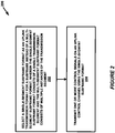
- Figure 2 illustrates an example method 200 performed by one or more UEs 102 for control signal transmission.
- the method 200 may include, at block 202, selecting a single-segment subframe format as an uplink transmission format for a subframe instead of a multi-segment subframe format.
- the UE may transmit one or more control signals on an uplink control channel using the single-segment subframe format.
- method 200 may include one or more additional aspects, such as the UE selecting the subframe format by recognizing that a component carrier (CC) switch is to be performed for a sounding reference signal (SRS) in a multi-segment subframe, determining that the CC switch would introduce a transmission delay that meets a time duration criterion, and selecting the uplink transmission format in response to determining that the time duration criterion is met.
- the single-segment subframe format comprises a bit-reduced version of at least one type of multi-segment subframe format.
- the single-segment subframe format utilizes a coding method utilized by at least one type of multi-segment subframe format.
- the selecting may include selecting the single-segment subframe format from a set of single-segment subframe formats.
- the method 200 may further include setting a power level at which to transmit the one or more control signals by utilizing transmission power otherwise allocated to a slot of the subframe that is not used for transmission of the one or more control signals according to the single-segment subframe format and transmitting the one or more control signals at the power level.
- the power level may be a power level greater than another power level utilized for an associated transmission of the one or more control signals when the multi-segment subframe is utilized.
- transmitting the one or more control signals using the single-segment subframe format may include selecting a single segment of two possible segments (e.g., slots, symbols, etc.) of the subframe during which the one or more control signals are to be transmitted.
- Method 200 may further include receiving, from a network node, an indication of which of a plurality of segments the uplink control channel should be transmitted using the single-segment subframe format, receiving, from the network node, an indication of a control channel frequency resource to be used to transmit the one or more control signals, the indication comprising one or more of a location of a downlink control channel received by the UE, and a resource indication carried within downlink control information on the downlink control channel.
- the method may include determining a physical resource block in which the one or more should be transmitted using the single-segment subframe format using the indication of the control channel resource and the slot in which the control channel is to be transmitted.
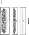
- Figure 3 illustrates an example method 300 performed by one or more network nodes 106 for controlling transmission of one or more control signals by a UE 102.
- the method 300 includes the network node 106 selecting a single-segment subframe format as an uplink transmission format for the one or more control signals transmitted by the UE in a subframe instead of a multi-segment subframe format at block 302.
- the network node 106 transmits an indication to the UE indicating that the one or more control signals are to be transmitted on an uplink control channel using the single-segment subframe format.
- the network node 106 receives the one or more control signals on the uplink control channel according to the single-segment subframe format, for example, based on the network node 106 transmitting the indication to the UE at block 304.
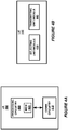
- FIG. 4A illustrates a UE 102, implemented in accordance with one or more embodiments.
- the UE 102 includes processing circuitry 400 (which may include at least one processor) and communication circuitry 410.
- the communication circuitry 410 is configured to transmit and/or receive information to and/or from one or more network nodes 106 via any communication technology. Such communication may occur via one or more antennas that are either internal or external to the UE 102.
- the processing circuitry 400 is configured to perform processing described above, e.g., in Figure 2 , such as by executing instructions stored in memory 420.
- the processing circuitry 400 in this regard may implement certain functional means, units, or modules.
- Figure 4B illustrates a UE 102 implemented in accordance with one or more other embodiments.
- the UE 102 implements various functional means, units, or modules, e.g., via the processing circuitry 400 in Figure 4A and/or via software code.
- These functional means, units, or modules, e.g., for implementing the method in Figure 2 include for instance a selecting unit or module 430 for selecting a single-segment subframe format as an uplink transmission format for a subframe.
- a transmitting unit or module 440 for transmitting one or more control signals on an uplink control channel using the single-segment subframe format.
- FIG. 5A illustrates a network node 106, such as a base station, eNB, or other network-side devices, implemented in accordance with one or more embodiments.
- the network node 106 includes processing circuitry 500 and communication circuitry 510.
- the communication circuitry 510 is configured to transmit and/or receive information to and/or from one or more UEs 102 and/or one or more other nodes, e.g., via any communication technology. Such communication may occur via one or more antennas that are either internal or external to the network node 106.
- the processing circuitry 500 is configured to perform processing described above, e.g., in Figure 3 , such as by executing instructions stored in memory 520.
- the processing circuitry 500 in this regard may implement certain functional means, units, or modules.
- Figure 5B illustrates a network node 106 implemented in accordance with one or more other embodiments.
- the network node 106 implements various functional means, units, or modules, e.g., via the processing circuitry 500 in Figure 5A and/or via software code.
- These functional means, units, or modules, e.g., for implementing the method in Figure 3 include for instance a selecting unit or module 530 for selecting a single-segment subframe format as an uplink transmission format for a UE for a subframe.
- a transmitting unit or module 540 for transmitting an indication to the UE 102 indicating that one or more control signals on an uplink control channel are to be transmitted using the single-segment subframe format.
- a receiving unit or module 550 is included for receiving the one or more control signals on the uplink control channel.
- embodiments herein further include corresponding computer programs.
- a computer program comprises instructions which, when executed on at least one processor or processing circuitry of a node, cause the node to carry out any of the respective processing described above.
- a computer program in this regard may comprise one or more code modules corresponding to the means or units described above.
- Embodiments further include a carrier containing such a computer program. This carrier may comprise one of an electronic signal, optical signal, radio signal, or computer readable storage medium.
- embodiments herein also include a computer program product stored on a non-transitory computer readable (storage or recording) medium and comprising instructions that, when executed by a processor, or processing circuitry, of a network node or UE, cause the node or UE to perform as described above.
- Embodiments further include a computer program product comprising program code portions for performing the steps of any of the embodiments herein when the computer program product is executed by a computing device.
- This computer program product may be stored on a computer readable recording medium.
- network node 106 may be considered as being performed by a single instance or device or may be divided across a plurality of instances of network node 106 that may be present in a given network/environment such that together the device instances perform all disclosed functionality.
- network node 106 may be any known type of device associated with a wireless communication network, radio communication network, or content delivery network, generally, that is known to perform a given disclosed processes or functions thereof. Examples of such network nodes include eNBs, gNBs (or other types of base stations or access points), Mobility Management Entities (MMEs), gateways, servers, and the like.
- MMEs Mobility Management Entities
- the UE 102 herein may be, or may be comprised of any wireless communication device that is able to communicate wirelessly with a wireless communication network, and may include, in some examples, mobile devices such as mobile phones, PDAs, tablets, computers (mobile or otherwise) laptops, or the like.
- the UE 102 may comprise an Internet-of-Things device, e.g. a device that performs monitoring or measurements, and transmits the results of such monitoring measurements to another device or a network.
- Such machines are power meters, industrial machinery, or home or personal appliances, e.g. refrigerators, televisions, personal wearables such as watches etc.
- a wireless communication device as described herein may be comprised in a vehicle and may perform monitoring and/or reporting of the vehicle's operational status or other functions associated with the vehicle.
- NR 5G New Radio
- LTE Long Term Evolution
- NR Long Term Evolution
- LTE Long Term Evolution
- NR Long Term Evolution
- An LTE slot corresponds to 7 OFDM symbols for normal CP, whereas an NR slot may correspond to 7 or 14 OFDM symbols; at 15 kHz subcarrier spacing, a slot with 7 OFDM symbols occupies 0.5 ms.
- Concerning NR terminology reference is made to 3GPP Technical Report 38.802 v14.0.0 and to Technical Specifications to appear in the 38 series.
- an LTE radio frame may be functionally equivalent to an NR frame, considering that both have a duration of 10 ms.
- An LTE subframe may be functionally equivalent to an NR slot with a corresponding number of OFDM symbols.
- An LTE eNB may be functionally equivalent to an NR gNB, since their functionalities as downlink transmitter are at least partially overlapping.
- a resource block (RB), which comprises 12 subcarriers ⁇ 1 slot, is the scheduling unit in LTE, that is, the smallest assignable resource.
- the LTE RB is comparable to the smallest assignable resource in NR, which is the shortest mini-slot, with a single OFDM symbol. Therefore, even though some embodiments of this disclosure have been described using LTE-originated terminology, they remain fully applicable to NR technology.
Description
- The present disclosure generally relates to a wireless communication system, and specifically relates to uplink control channel transmissions within the wireless communication system.
- In current wireless communication systems, a user equipment (UE) communicates with a network node (such as a base station, eNB, or other network device) to receive data over one or more downlink channels in a cell associated with the network node. To maintain channel and data transfer integrity, the UE may likewise transmit control signaling to the network node on one or more uplink channels. For instance, uplink control signaling from the UE to the network node can include hybrid automatic repeat request (HARQ or H-ARQ) acknowledgements for received downlink data, UE reports related to the downlink channel conditions that are used as assistance for the downlink scheduling, and/or scheduling requests indicating that the UE requires uplink resources for uplink data transmissions.
- This uplink control signaling can be transmitted, for example, on a Physical Uplink Control Channel (PUCCH), which presently adheres to a multi-segment subframe structure according to which uplink control signal transmissions are scheduled by a network node in the time and frequency domains. Specifically, a typical Long-Term Evolution (LTE) subframe is 1ms in length and contains two 0.5ms slots each having a number (e.g., six or seven) of symbols. A number of resource elements corresponding to the available system bandwidth are allocated by a network-side scheduler to one or more UEs in a cell for uplink control transmission during the subframe.
- In some subframes, one or more resource elements in a final symbol of the subframe (in the second slot) is reserved for UE transmission of a sounding reference signal (SRS), which is received by the network node and processed to determine characteristics (e.g., channel quality, interference, etc.) of the uplink control channel. In some instances, the UEs may be configured to perform frequency hopping for Sounding Reference Signal (SRS) transmissions. When such switching occurs, a delay in SRS transmission may occur as a result of a signal amplifier adjusting a power level from a first power level associated with PUCCH transmissions to a second power level associated with SRS transmission. In some cases, this delay does not affect control signal transmission or overall performance in the cell. Where, however, the delay reaches a threshold duration (e.g., ∼symbol duration), the SRS may be delayed enough so as to overlap in time and frequency with scheduled PUCCH transmissions in the cell, causing signal "collision." To avoid this scenario, which introduces interference that can render one or both of the SRS and PUCCH undiscernible by the receiver, one or more subsequent slots may be cancelled, or "dropped," resulting in wasted system resources and decreased system throughput.
- Thus, improved uplink control frame structures and related techniques for uplink signal scheduling are needed to improve system performance in situations where signal collision occurs or may occur.
-
US2014078942A1 discloses a method in which a user equipment accommodates an SRS transmission by selecting a shortened PUCCH format instead of a regular PUCCH format. In the shortened PUCCH format, the last symbol of a subframe is punctured.US8954064B2 andWO2013067430A1 disclose PUCCH shortening similar to the one ofUS2014078942A1 . XP051089975 (3GPP draft R1-164446, May 2016) proposes further techniques for avoiding collision of SRS switching and PUCCH, including signaling of HARQ reference subframes. - The invention is defined by the appended claims 1-16. The embodiments that do not fall under the scope of the claims have to be interpreted as examples useful for understanding the invention.
- One or more embodiments herein can employ multiple different potential single-segment subframes that define different possible techniques for transmitting uplink control data on an uplink control channel in a wireless environment. Some embodiments may therefore dynamically select a format for one or more uplink subframes from one of the multiple different potential single-segment subframe formats and multi-segment subframe formats. In some examples, a network node or the UE operating in a cell may select a single-segment subframe format for the subframe where it is determined that SRS hopping is implemented by the UE and/or an actual or potential collision event is detected between the SRS and other uplink data in the cell. Allowing a single-segment subframe to be dynamically selected in this way may, for example, advantageously avoid collision between uplink transmission in the cell and the potential dropping of one or more uplink transmission slots that can result from collision.
- More particularly, embodiments herein include a method performed by a UE for control signal transmission, which may include selecting a single-segment subframe format as an uplink transmission format for a subframe instead of a multi-segment subframe format. In addition, such a method may include the UE transmitting one or more control signals on an uplink control channel using the single-segment subframe format. The selection may be temporary, wherein the UE applies the single-segment subframe format for a specific amount of time and then reverts to the multi-segment subframe format; alternatively, the single-segment subframe format may be applied in an open-ended fashion, e.g., until the multi-segment subframe format is selected, until control transmissions are interrupted, or the like. Further alternatively, the UE may decide to switch between transmitting the single-segment subframe format (e.g., a short PUCCH format) and the multi-segment subframe format (e.g., a long PUCCH format), depending on the size and/or the content of Uplink Control Information to be transmitted; this may be practiced regardless of whether a component carrier switch is to be performed for a sounding reference signal.
- Embodiments herein also include corresponding apparatus, computer programs, and carriers (e.g., computer program products), as well as network-side aspects performed by a network node.
-
-
Figure 1 is a block diagram of a wireless communication system according to one or more embodiments. -
Figure 2 is a logical flow diagram illustrating a method performed by a UE according to one or more embodiments. -
Figure 3 is a logical flow diagram illustrating a method performed by a network node according to one or more embodiments. -
Figure 4A is a block diagram of a UE according to one or more embodiments. -
Figure 4B is a block diagram of a UE according to one or more other embodiments. -
Figure 5A is a block diagram of a radio node according to one or more embodiments. -
Figure 5B is a block diagram of a radio node according to one or more other embodiments. -
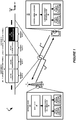
Figure 1 illustrates awireless communication system 10 according to one or more embodiments. Thesystem 10 includes a network node 106 (such as, but not limited to, a base station, eNB, gNB, etc). Thesystem 10 also includes a UE 102 (also referred to herein as a "terminal, "user terminal," or the like) in communication with thenetwork node 106. This communication, in addition to uplink and downlink transmission of user/application data, may includeuplink control signaling 20 anddownlink control signaling 18. In some examples, theuplink control signaling 20 may be performed over a PUCCH or Physical Uplink Shared Channel (PUSCH). In some examples, if the UE 102 has been assigned resources for data transmission in the current subframe, uplink control information (including HARQ acknowledgements) is transmitted together with data on the PUSCH. On the PUCCH, if the terminal has not been assigned resources for data transmission in the current subframe, uplink control information is transmitted separately from user data, using resource blocks specifically assigned for the purpose. Theuplink control signaling 20 may include HARQ acknowledgements for received downlink data, terminal reports related to the downlink channel conditions, uplink scheduling requests, and/or SRS transmissions. Thedownlink control signaling 18 may include uplink control channel scheduling data, one or more indications related to a subframe format to be utilized by the UE 102 in uplink transmissions during particular subframes, or any other control signaling related to the UE 102 or any other UEs in a cell in which the communication is taking place. - The present disclosure relates at least to uplink control signaling transmitted by a UE 102 on a PUCCH. In some examples, PUCCH time-frequency resources are located at the edges of the total available cell bandwidth, where each such resource consists of twelve subcarriers (e.g., one resource block) within each of the two segments (e.g. two slots) of an uplink subframe. In order to provide frequency diversity, these frequency resources undergo frequency hopping on the slot boundary, i.e. one "resource" consists of 12 subcarriers at the upper part of the spectrum within the first slot of a subframe and an equally sized resource at the lower part of the spectrum during the second slot of the subframe (or vice versa). If more resources are needed for the uplink Layer1/Layer2 (L1/L2) control signaling, e.g. in case of very large overall transmission bandwidth supporting a large number of users, additional resources blocks can be assigned next to the previously assigned resource blocks.
- As mentioned above, uplink L1/L2 control signaling includes hybrid-ARQ acknowledgements, channel-status reports, and scheduling requests. Different combinations of these types of messages are possible by using one of available
multi-segment subframe formats 22, which are capable of carrying different numbers of bits. - The bandwidth of one resource block during one subframe is too large for the control signaling needs of a single terminal. Therefore, to efficiently exploit the resources set aside for control signaling, multiple terminals can share the same resource block. This is done by assigning the different terminals different orthogonal phase rotations of a cell-specific length-12 frequency-domain sequence. The resource used by a PUCCH is therefore not only specified in the time-frequency domain by the resource-block pair, but also by the phase rotation applied. Similarly to the case of reference signals, there are up to twelve different phase rotations specified, providing up to twelve different orthogonal sequences from each cell-specific sequence. However, in the case of frequency-selective channels, not all the twelve phase rotations can be used if orthogonality is to be retained. Typically, up to six rotations are considered usable in a cell.
-
Layer 1/Layer 2 is used for hybrid-ARQ acknowledgements and scheduling requests on the PUCCH. It is capable of carrying up to two information bits in addition to Discontinuous Transmission (DTX), whereby if no information transmission was detected in the downlink, no acknowledgement is generated in the uplink. Hence, there are three or five different combinations, depending on whether MIMO was used on the downlink or not:Combination No MIMO MIMO 1st transport block 2nd transport block 1 ACK ACK ACK 2 NAK ACK NAK 3 DTX NAK ACK 4 NAK NAK 5 DTX - Currently, several PUCCH "formats" are utilized for PUCCH communication in a particular LTE Release 13 subframe. For purposes of the present disclosure, these presently-utilized PUCCH formats are referred to herein as "legacy" PUCCH formats, Release 13 PUCCH formats, multi-segment (or multi-slot) subframe formats 22, or simply PUCCH formats. These legacy formats will be described below, along with the presently proposed single-segment (e.g., single-slot) subframe formats 21.
- For instance, legacy PUCCH format 1 (three formats, 1, 1a, and 1b, exist in the current specifications, although herein they are all referred to as
format 1 for simplicity) uses the same structure in the two segments (e.g., slots, symbols, etc.) of a subframe. For transmission of a hybrid-ARQ acknowledgement, the single hybrid-ARQ acknowledgement bit is used to generate a BPSK symbol (in case of downlink spatial multiplexing the two acknowledgement bits are used to generate a Quadrature Phase Shift Keying (QPSK) symbol). For a scheduling request, on the other hand, the Binary Phase Shift Keying (BPSK)/ QPSK symbol is replaced by a constellation point treated as negative acknowledgement at the eNodeB. The modulation symbol is then used to generate the signal to be transmitted in each of the two PUCCH slots. - Channel-status reports are used to provide the eNodeB with an estimate of the channel properties at the terminal in order to aid channel-dependent scheduling. A channel-status report consists of multiple bits per subframe.
PUCCH format 1, which is capable of at most two bits of information per subframe, can obviously not be used for this purpose. Transmission of channel-status reports on the PUCCH is instead handled by PUCCH format 2, which is capable of multiple information bits per subframe (there are actually three variants in the LTE specifications, formats 2, 2a and 2b, where the last two formats are used for simultaneous transmission of hybrid-ARQ acknowledgements as discussed below - for simplicity, they are all referred to as format 2 herein). PUCCH format 2 is based on a phase rotation of the same cell-specific sequence asformat 1. - PUCCH format 3 is designed for carrier aggregation purpose. The multiple ACK/NACK bits are encoded to form 48 coded bits. The coded bits are then scrambled with cell-specific (and possibly Discrete Fourier Transform Spreading Orthogonal Frequency Division Multiplexing (DFTS-OFDM) symbol dependent) sequences. In PUCCH format 3, 24 bits are transmitted within the first slot and the other 24 bits are transmitted within the second slot. The 24 bits per slot are converted into 12 QPSK symbols, Discrete Fourier Transform (DFT) precoded, spread across five DFTS-OFDM symbols and transmitted within one resource block (bandwidth) and five DFTS-OFDM symbols (time). In addition, PUCCH format 3 UE-specific spreading sequence that enables multiplexing of up to five users within the same resource blocks.
- PUCCH formats 4 and 5 are extension of format 3 that allow more HARQ data to be transmitted. This stems from the extension of carrier aggregation in Release 13, allowing up to 32 component carriers. Format 4 uses 144 blocks of QPSK symbols spread over the two slots. No cyclic shift is used so that every symbol can transmit 2 HARQ coded bits. Each block corresponds to one resource block (12 subcarriers) in the frequency domain. In the time domain, the first slot is occupied by 6 data OFDM symbols and 1 reference signal OFDM symbol, and the second slot contains 5 data symbol and 2 reference symbols.
- PUCCH format 5 is similar to format 4 and uses 72 QPSK symbols spread over two slots. Size 2 code division multiplexing allows the multiplexing of users. Format 5 occupies one resource block (12 subcarrier) in the frequency domain. In the time domain, the two slots are each occupied by 6 data OFDM symbols and 1 reference signal OFDM symbol.
- In addition, the use of LTE carrier aggregation (CA), introduced in
Release 10 and enhanced in Release 11, offers means to increase the peak data rates, system capacity and user experience by aggregating radio resources from multiple carriers that may reside in the same band or different bands and, for the case of inter-band TDD CA, may be configured with different UL/DL configurations. In Release 12, carrier aggregation between TDD and FDD serving cells is introduced to support UE connecting to them simultaneously. - In Release 13, LAA (Licensed-Assisted Access) has attracted significant interest for its potential to extend the LTE carrier aggregation feature toward capturing the spectrum opportunities of unlicensed spectrum in the 5GHz band. WLAN operating in the 5GHz band already supports 80MHz in the field and 160MHz is to follow in Wave 2 deployment of IEEE 802.11ac. There are also other frequency bands, such as 3.5 GHz, where aggregation of more than one carrier on the same band is possible, in addition to the bands already widely in use for LTE. Enabling the utilization of at least similar bandwidths for LTE in combination with LAA as IEEE 802.11ac Wave 2 will support calls for extending the carrier aggregation framework to support more than 5 carriers. The extension of the CA framework beyond 5 carriers was approved to be one work item for LTE Release 13. The objective is to support up to 32 carriers in both UL and DL.
- Compared to single-carrier operation, a UE operating with CA has to report feedback for more than one DL component carrier. Meanwhile, a UE does not need to support DL and UL CA simultaneously. For instance, the first release of CA-capable UEs in the market only supports DL CA (and not UL CA). This is also the underlying assumption in the 3GPP RAN4 standardization. Therefore, an enhanced UL control channel, i.e. PUCCH format 3 was introduced for CA during
Release 10 timeframe. However, in order to support more component carriers in Release 13, the UL control channel capacity becomes a limitation;
In carrier aggregation, PUCCH transmission can be done with two different ways. The first method is based on the use of PUCCH format 3 that is based on DFTS-OFDM. The second CA PUCCH method is called channel selection. The basic principle is that the UE is assigned a set of PUCCH format 1a/1b resources. The UE then selects one of resources according to the ACK/NACK sequence the UE should transmit. On one of the assigned resource the UE would then transmit a QPSK or BPSK. The eNB detects which resource the UE uses and which QPSK or BPSK value the UE fed back on the used resource, and combines this into a HARQ response for associated DL cells. - As discussed briefly above, delays associated with SRS transmission (e.g., in SRS frequency hopping scenarios, have been known to cause a delay that meets a certain criterion (e.g., has a duration greater than (or sometimes also equal to) a threshold duration) that if met, causes the
network node 106 and/or theUE 102 to determine that one or more slots should be dropped (i.e., the uplink control data transmissions over the PUCCH for these one or more slots are canceled or delayed). Although helping to ensure that collision is avoided, these delays introduce performance losses and, potentially, the loss of data transmissions altogether (e.g., the transmissions for the dropped slots are not subsequently transmitted). The discussion on SRS based carrier switching/hopping started in RAN1#84b [1-3]. In the present invention, the impact of handling collisions (between transmitting SRS on another CC and PUCCH or PUSCH channels in the CA CC from which the switching is done) is discussed and several novel solutions to handle the dropping of slots are proposed. - The impact of collision is highly dependent on how long interruption time is introduced by the switching of SRS. A few microseconds can be handled on the requirement level as a RAN4 issue. Requirement specifications (e.g., 3GPP 36.101) have specified transition delay tolerances to allow power amplifiers to switch between PUCCH and SRS power levels. If the switching time is within the same order of magnitude, RAN4 can adjust the requirements. If the switching delay meets a criterion (e.g., is on the order of a SC-OFDM symbol length or more, etc.) there can be an impact in network performance and capacity at least in term of PUCCH/PUSCH throughput which in turn leads to drops in network user capacity. SRS-based carrier switching does not currently have a standardized solution to handle dropping of slots which cannot be transmitted due to the interruption time needed to switch between component carriers.
- Accordingly, one non-limiting objective of the example embodiments described herein is to maintain as much of a payload of a control signal subframe when one of the two segments (e.g., slots, symbols, etc.) must be dropped (i.e., transmissions scheduled for the dropped segment/slot are not transmitted). To meet this end, the present application describes several non-limiting subframe structures that utilize one segment instead of the two segments (e.g., where the segment can be a slot of a Release 13 subframe, for instance, though this is not a limiting aspect). Such a structure is illustrated in subframe N of
Figure 1 , wherein uplink control transmissions occur in one of the slots (inFigure 1 ,slot 0 of subframe N, although they may occur alternatively in slot 1) and do not occur in the other slot (inFigure 1 ,slot 0 of subframe N). For instance, in some embodiments herein, PUCCH formats 1, 1a, 1b, 3, 4, and 5 (described above) are compressed to one of the two slots that Release 13 PUCCH formats occupy (see, e.g.,slots Figure 1 , which has a multi-segment (specifically, multi-slot) subframe format according to, for example, those utilized presently in Release 13 implementations). In some embodiments, PUCCH Channel State Information (CSI) reporting payloads are halved to compensate for the loss of half the PUCCH resource and power offsets can compensate for the loss of the second slot. Release 13 reference signal designs, channel coding, interleaving, rate matching, and slot structures can be used along with the above aspects. As such, the present embodiments allows UEs/network nodes to communicate control information during a single segment (e.g., single slot) in a subframe when the UE must drop one slot (as it is the case in SRS carrier based switching). - Accordingly, the description below describes several potential single-segment subframe formats 21, which can be selected for use in one or more subframes by
network node 106 orUE 106, for instance, by processing executed in acontrol signal manager 32 of theUE 102 or ascheduler 28 of the network node. For purposes of the present disclosure, the term "segment" (as used in the terms single-segment, multi-segment, and the like) may refer to any time and/or frequency resource group used to model a wireless communication channel, such as, but not limited to, a slot, a symbol, or any other related entity known in the art. - In some examples described herein, the
network node 106 andUE 102 may negotiate as to which of a single-segment subframe format 21 ormulti-segment subframe format 22 to utilize, or one of thenetwork node 106 or theUE 102 may be charged with making such a determination. In some examples, this determination may include determining whether an SRS is to be transmitted by the UE during a particular segment and/or subframe, whether frequency hopping between segments/subframes is utilized by theUE 102, and/or whether a delay associated with the SRS transmission or frequency hopping causes or may cause a delay that meets a particular criterion for selecting a single-segment subframe format 21 instead of amulti-segment subframe format 22. - In a further aspect, the
control signal manager 32 and/or thescheduler 28 may be configured to adjust a power level associated with transmissions during a slot when a single-segment subframe format 21 is selected for a subframe. As described in further detail below, this may include increasing the power of transmissions during the single segment of the subframe by a residual amount corresponding to power that will be unused for transmissions in the other slot of the subframe. - In addition, as introduced above, when a single-
segment subframe format 21 is selected instead of amulti-segment subframe format 22, thenetwork node 106 and/orUE 102 may choose between multiple potential single-segment subframe formats 21 available to be utilized. Examples of these available single-segment subframe formats will now be described in detail, some of which are described in relation to the multi-segment subframe formats 22 described above (i.e., Release 13 two-slot subframe formats). In certain example embodiments, the number of acknowledgement/negative acknowledgement (A/N or ACK/NACK) bits carried in single-segment PUCCH formats 1, 1a, and 1b is the same as the corresponding Release 13 (i.e. "legacy") formats, as the second slot can carry the same information asslot 1. This can be true when channel selection is or is not configured for the UE. In addition, power can be adjusted to account to the available power of the dropped slot, i.e. the first slot is now scaled with additional power previously available for the second slot. - In addition, according to the present disclosure, formats 2, 2a, and 2b can carry from 20 to 22 bits of payload (20 coded bits of CSI plus up to two bits of HARQ-ACK), corresponding to 10 CSI bits and 2 bits of HARQ-ACK. In order to carry that payload over a single segment, such as a single slot, it is proposed to use the coding and slot structure from PUCCH format 3 in the slot.
- The slot structure and coding of PUCCH format 3 could replace formats 2, 2a, and 2b, and therefore be labeled 'PUCCH format 2c'. The same 11 bit Reed-Muller code would be used for CSI, and with CSI + up to 2 bit A/N. If used for TDD, format 2c may be used in subframes where only A/N for the primary cell is needed, and when the UE is configured with HARQ-ACK bundling, HARQ-ACK multiplexing or PUCCH format 1b with channel selection, since the number of A/N bits can be 2 in such cases. Power is adjusted to account to the available power of the dropped slot i.e. the first slot is now scaled with additional power previously available for the second slot.
- In example embodiments of the present disclosure, if multiplexing more than 2 A/N bits with CSI is desired in Release 13 LTE sytems, legacy PUCCH format 3 may be used. If, however, a slot must be dropped, a single-segment format 3 can be used. For this single-segment subframe format, PUCCH dropping rules for format 3 (e.g., as defined in section 7.3.2 of 3GPP 36.213) are used, except that the rules that drop PUCCH content at 22 bits now drop with 12 bits. Furthermore, instead of 20 bits HARQ-ACK with 1 bit SR as in legacy PUCCH format 3, at most 10 bits HARQ-ACK and 1 bit SR is carried on single-segment PUCCH 3 of the present disclosure. In some embodiments, the 11 bit Reed-Muller code could still be used, with corresponding new rules for coding less than 11 bits containing both A/N and CSI, since A/N is not multiplexed with CSI for less than 11 bits in Release 13. In addition, power can be adjusted to account to the available power of the dropped slot i.e. the first slot is now scaled with additional power previously available for the second slot.
- In any event, the maximum of transmitted HARQ-ACK bits in the single-segment PUCCH format 3 is less than in the legacy PUCCH format 3, and so may be considered as a smaller version of PUCCH format 3, e.g. 'format 3b'. Alternatively, given that the payload size is similar to PUCCH format 2, it may be considered as a new PUCCH format 2 that allows CSI and HARQ-ACK to be multiplexed, e.g. a 'format 2d'.
- PUCCH format 5 (with normal CP) can carry 12 subcarriers / 2 CDM users × 6 symbols/slot × 2 slots × 2 bit QPSK = 144 channel bits. If only one slot is used, then 72 channel bits can be carried.
- So, the number of channel bits when PUCCH format 5 is shortened to one slot can somewhat exceed the 48 bits in PUCCH format 3. A simple solution (similar to 'format 2c' above) then would be to create a new PUCCH format using a single-segment of PUCCH format 5 that exactly follows the behavior of PUCCH format 3 with respect to coding and CSI dropping rules. Such a new format would carry no more than 21 bits payload. This new format could be used to construct a second version of PUCCH format 3, e.g. a 'PUCCH format 3a', and be used in place of PUCCH format 3 for when a UE needs to transmit PUCCH format 3 but must also transmit only in one slot in a given subframe. For example, when a UE configured for PUCCH formats 3, 4, or 5 determines that PUCCH format 3 should be used (according to Release 13), but only one slot is available to transmit PUCCH, then PUCCH format 3a would be used instead.
- Similar to PUCCH format 5, format 4 allows several blocks of 144 bits (72QPSK symbols) per slots, or 288 coded bits per subframes.
- Single-segment subframe formats based on PUCCH formats 4 and 5, e.g. 'format 4a', and 'format 5a' could behave similarly, transmitting in only one slot while using Release 13 dropping rules changed to compensate for half of the REs being available as payload. For example, the dropping criterion with HARQ-ACK and CSI present for PUCCH format 4 configured with two sizes, changes to:


- For PUCCH format 4 or 5, this parameter is set to


- Furthermore, because legacy PUCCH format 5 supports a variety of code rates (from 0.08 to 0.8), single-segment PUCCH format 5 as described herein can allow from 4 to 48 bits payload (e.g., information bits). Therefore, if a UE transmits using the legacy PUCCH format 3 (20bits HARQ plus a one-bit scheduling request) but is constrained to use only one segment, the single-segment format 5 could be utilized as a viable improvement over existing formats.
- As introduced above, one or both of the
network node 106 and theUE 102 may adjust the transmission power for control signal transmissions in the single utilized slot of a single-segment subframe format. Embodiments that adjust power to account for the available power of the dropped slot may use an additional factor in the UE power control calculations. One such embodiment uses a factor Δ slot (i) that increases the transmitted power of PUCCH in subframes where the UE transmits a single-segment PUCCH format relative to subframes where the UE transmits a Release 13 PUCCH format. This may be expressed as
- min{a, b} is the minimum of a and b, where a and b are real numbers,
- P' PUCCH (i) is the power the UE should transmit in dB after being adjusted for operating with a single PUCH slot format configured, and
- PPUCCH (i) is calculated according to section 5.1.2.1 of 3GPP TS 36.213 rev. 13.2.0
- Furthermore, Δ slot (i) is 0 in subframes where UE transmits Release 13 PUCCH formats, and is a non-zero value in a subframe when the UE transmits a single-segment PUCCH format. The non-zero value may be 3 dB in some embodiments. In other embodiments the value of Δ slot (i) in subframes where the UE transmits a single-segment PUCCH format is set by higher layers, for example using an RRC configured parameter or a value provided in a MAC control element.
- In addition, the equation above for P' PUCCH (i) may be equivalently expressed by incorporating Δ slot (i) in the Release 13 power control expressions for PPUCCH (i). For example, If serving cell c is the primary cell, for
PUCCH format 1/1a/1b/2/2a/2b/3, the setting of the UE Transmit power P PUCCH for the physical uplink control channel (PUCCH) transmission in subframe i for serving cell c is defined in Release 13 as:
- This can be extended to support when single-segment PUCCH formats can be transmitted by the UE by including Δ slot (i) as shown below:

- In addition to adjusting power levels for single-segment subframe control signal transmissions, the network node 106 (or in some cases, the
UE 102 based on a predetermined pattern/timing reference) can select a particular slot (e.g.,slot 0 orslot 1 of the subframes ofFigure 1 ) during which control signal transmission occurs and, accordingly, the slot during which no such control signal transmission occurs. For example, because existing PUCCH formats (includingformats 1, 1a, 1b, 2, 2a, 2b, 3, 4, and 5) frequency hop once per slot, it is not possible to support PUCCH frequency hopping in one subframe. However, the Release 13 PUCCH resource principles can be used, where a PUCCH's transmission in even slots is at the low end of the band, and at the high end of the band in odd slots, i.e. according to the following:
- In such cases, a UE transmitting single-segment PUCCH formats 1, 1a, 1b, 4 or 5, or the new formats 2c, 3a, 4a, or 5a, can be allocated either the even or odd slot to transmit PUCCH in a given subframe, and accordingly could transmit only when ns mod 2 = 0 or when ns mod 2=1, respectively. Single-segment PUCCH resource could therefore be defined as the Release 13
PUCCH format 1, 1a, 1b, 3, 4, or 5 resource plus whether the UE transmits a single-segment PUCCH format in a given subframe when ns mod 2 = 0 or when ns mod 2=1. Then existing PUCCH resource allocation mechanisms (implicit allocation, ARI, and ARO) can be used to determine the PRBs for both slots, and the RRC configured slot selects which RB(s) the UE will transmit on. - Therefore, as described above, aspects of the presently disclosed embodiments and techniques include selecting and utilizing single-segment subframe formats, each of which may constitute a shortened format relative to existing, or "legacy" formats. This allows the
network node 106 andUE 102 to maximize the signaling payload that can be communicated in a given timeframe, while advantageously utilizing coding methods with which the devices are already configured to communicate. In addition, the aspects of the present disclosure introduce techniques for optimizing transmission power for transmissions during a single subframe slot and for selecting a slot so as to maximize the effective slot usage on a cell-wide basis (i.e., for multiple users in a particular cell). -
Figure 2 illustrates anexample method 200 performed by one ormore UEs 102 for control signal transmission. Themethod 200 may include, atblock 202, selecting a single-segment subframe format as an uplink transmission format for a subframe instead of a multi-segment subframe format. In addition, atblock 204, the UE may transmit one or more control signals on an uplink control channel using the single-segment subframe format. - In addition, although not explicitly recited in
Figure 2 ,method 200 may include one or more additional aspects, such as the UE selecting the subframe format by recognizing that a component carrier (CC) switch is to be performed for a sounding reference signal (SRS) in a multi-segment subframe, determining that the CC switch would introduce a transmission delay that meets a time duration criterion, and selecting the uplink transmission format in response to determining that the time duration criterion is met. In an aspect, the single-segment subframe format comprises a bit-reduced version of at least one type of multi-segment subframe format. Furthermore, the single-segment subframe format utilizes a coding method utilized by at least one type of multi-segment subframe format. The selecting may include selecting the single-segment subframe format from a set of single-segment subframe formats. Themethod 200 may further include setting a power level at which to transmit the one or more control signals by utilizing transmission power otherwise allocated to a slot of the subframe that is not used for transmission of the one or more control signals according to the single-segment subframe format and transmitting the one or more control signals at the power level. The power level may be a power level greater than another power level utilized for an associated transmission of the one or more control signals when the multi-segment subframe is utilized. Moreover, transmitting the one or more control signals using the single-segment subframe format may include selecting a single segment of two possible segments (e.g., slots, symbols, etc.) of the subframe during which the one or more control signals are to be transmitted.Method 200 may further include receiving, from a network node, an indication of which of a plurality of segments the uplink control channel should be transmitted using the single-segment subframe format, receiving, from the network node, an indication of a control channel frequency resource to be used to transmit the one or more control signals, the indication comprising one or more of a location of a downlink control channel received by the UE, and a resource indication carried within downlink control information on the downlink control channel. Furthermore, the method may include determining a physical resource block in which the one or more should be transmitted using the single-segment subframe format using the indication of the control channel resource and the slot in which the control channel is to be transmitted. -
Figure 3 illustrates anexample method 300 performed by one ormore network nodes 106 for controlling transmission of one or more control signals by aUE 102. For example, themethod 300 includes thenetwork node 106 selecting a single-segment subframe format as an uplink transmission format for the one or more control signals transmitted by the UE in a subframe instead of a multi-segment subframe format atblock 302. In addition, atblock 304, thenetwork node 106 transmits an indication to the UE indicating that the one or more control signals are to be transmitted on an uplink control channel using the single-segment subframe format. Furthermore, atblock 306, thenetwork node 106 receives the one or more control signals on the uplink control channel according to the single-segment subframe format, for example, based on thenetwork node 106 transmitting the indication to the UE atblock 304. -
Figure 4A illustrates aUE 102, implemented in accordance with one or more embodiments. As shown, theUE 102 includes processing circuitry 400 (which may include at least one processor) and communication circuitry 410. The communication circuitry 410 is configured to transmit and/or receive information to and/or from one ormore network nodes 106 via any communication technology. Such communication may occur via one or more antennas that are either internal or external to theUE 102. Theprocessing circuitry 400 is configured to perform processing described above, e.g., inFigure 2 , such as by executing instructions stored inmemory 420. Theprocessing circuitry 400 in this regard may implement certain functional means, units, or modules. -
Figure 4B illustrates aUE 102 implemented in accordance with one or more other embodiments. As shown, theUE 102 implements various functional means, units, or modules, e.g., via theprocessing circuitry 400 inFigure 4A and/or via software code. These functional means, units, or modules, e.g., for implementing the method inFigure 2 , include for instance a selecting unit ormodule 430 for selecting a single-segment subframe format as an uplink transmission format for a subframe. Also included is a transmitting unit ormodule 440 for transmitting one or more control signals on an uplink control channel using the single-segment subframe format. -
Figure 5A illustrates anetwork node 106, such as a base station, eNB, or other network-side devices, implemented in accordance with one or more embodiments. As shown, thenetwork node 106 includesprocessing circuitry 500 andcommunication circuitry 510. Thecommunication circuitry 510 is configured to transmit and/or receive information to and/or from one ormore UEs 102 and/or one or more other nodes, e.g., via any communication technology. Such communication may occur via one or more antennas that are either internal or external to thenetwork node 106. Theprocessing circuitry 500 is configured to perform processing described above, e.g., inFigure 3 , such as by executing instructions stored inmemory 520. Theprocessing circuitry 500 in this regard may implement certain functional means, units, or modules. -
Figure 5B illustrates anetwork node 106 implemented in accordance with one or more other embodiments. As shown, thenetwork node 106 implements various functional means, units, or modules, e.g., via theprocessing circuitry 500 inFigure 5A and/or via software code. These functional means, units, or modules, e.g., for implementing the method inFigure 3 , include for instance a selecting unit ormodule 530 for selecting a single-segment subframe format as an uplink transmission format for a UE for a subframe. Also included is a transmitting unit ormodule 540 for transmitting an indication to theUE 102 indicating that one or more control signals on an uplink control channel are to be transmitted using the single-segment subframe format. In addition, a receiving unit ormodule 550 is included for receiving the one or more control signals on the uplink control channel. - Those skilled in the art will also appreciate that embodiments herein further include corresponding computer programs. A computer program comprises instructions which, when executed on at least one processor or processing circuitry of a node, cause the node to carry out any of the respective processing described above. A computer program in this regard may comprise one or more code modules corresponding to the means or units described above. Embodiments further include a carrier containing such a computer program. This carrier may comprise one of an electronic signal, optical signal, radio signal, or computer readable storage medium. In this regard, embodiments herein also include a computer program product stored on a non-transitory computer readable (storage or recording) medium and comprising instructions that, when executed by a processor, or processing circuitry, of a network node or UE, cause the node or UE to perform as described above. Embodiments further include a computer program product comprising program code portions for performing the steps of any of the embodiments herein when the computer program product is executed by a computing device. This computer program product may be stored on a computer readable recording medium.
- Furthermore, the processing or functionality of
network node 106 may be considered as being performed by a single instance or device or may be divided across a plurality of instances ofnetwork node 106 that may be present in a given network/environment such that together the device instances perform all disclosed functionality. In addition,network node 106 may be any known type of device associated with a wireless communication network, radio communication network, or content delivery network, generally, that is known to perform a given disclosed processes or functions thereof. Examples of such network nodes include eNBs, gNBs (or other types of base stations or access points), Mobility Management Entities (MMEs), gateways, servers, and the like. - In any scenario discussed above, the
UE 102 herein may be, or may be comprised of any wireless communication device that is able to communicate wirelessly with a wireless communication network, and may include, in some examples, mobile devices such as mobile phones, PDAs, tablets, computers (mobile or otherwise) laptops, or the like. In addition theUE 102 may comprise an Internet-of-Things device, e.g. a device that performs monitoring or measurements, and transmits the results of such monitoring measurements to another device or a network. Particular examples of such machines are power meters, industrial machinery, or home or personal appliances, e.g. refrigerators, televisions, personal wearables such as watches etc. In other scenarios, a wireless communication device as described herein may be comprised in a vehicle and may perform monitoring and/or reporting of the vehicle's operational status or other functions associated with the vehicle. - The 3GPP has issued agreements concerning 5G New Radio (NR) terminology in the period between the earliest priority date and the filing date of the present disclosure. NR terminology and LTE terminology coincide to a considerable extent. For instance, a resource element (RE) remains 1 subcarrier × 1 OFDM symbol. Yet some terms known in LTE have been given a new meaning in NR. The present disclosure, including the claims, applies prefixes "LTE" and "NR" to clarify the relevant technical context. For instance, an LTE subframe lasting 1 ms contains 14 OFDM symbols for normal CP, whereas an NR subframe has a fixed duration of 1 ms and may therefore contain a different number of OFDM symbols for different subcarrier spacings. An LTE slot corresponds to 7 OFDM symbols for normal CP, whereas an NR slot may correspond to 7 or 14 OFDM symbols; at 15 kHz subcarrier spacing, a slot with 7 OFDM symbols occupies 0.5 ms. Concerning NR terminology, reference is made to 3GPP Technical Report 38.802 v14.0.0 and to Technical Specifications to appear in the 38 series.
- A non-prefixed term in this disclosure is to be understood in the LTE sense unless otherwise stated. However, any term designating an object or operation known from LTE is expected to be reinterpreted functionally in view of NR specifications. For instance, an LTE radio frame may be functionally equivalent to an NR frame, considering that both have a duration of 10 ms. An LTE subframe may be functionally equivalent to an NR slot with a corresponding number of OFDM symbols. An LTE eNB may be functionally equivalent to an NR gNB, since their functionalities as downlink transmitter are at least partially overlapping. A resource block (RB), which comprises 12 subcarriers × 1 slot, is the scheduling unit in LTE, that is, the smallest assignable resource. The LTE RB is comparable to the smallest assignable resource in NR, which is the shortest mini-slot, with a single OFDM symbol. Therefore, even though some embodiments of this disclosure have been described using LTE-originated terminology, they remain fully applicable to NR technology.
- The invention is defined by the appended claims 1-16.
Claims (16)
- A method (200) performed by a user equipment (102) for control signal transmission, characterized by:selecting (202) a single-segment subframe format as an uplink transmission format for a subframe instead of a multi-segment subframe format (22), wherein the single-segment subframe format (21) consists of a single transmission segment and the multi-segment subframe format (22) consists of multiple instances of the transmission segment, wherein the transmission segment corresponds to a symbol; andtransmitting (204) one or more control signals on an uplink control channel using the single-segment subframe format.
- The method of claim 1, wherein said selecting depends on a size of Uplink Control Information to be transmitted.
- The method of any of claims 1-2, wherein the selecting (202) further comprises:recognizing that a component carrier switch is to be performed for a sounding reference signal, SRS, in a multi-segment subframe;determining that the component carrier switch would introduce a transmission delay that meets a time duration criterion; andselecting the uplink transmission format in response to determining that the time duration criterion is met.
- The method of any of claims 1-3, wherein the single-segment subframe format (21) comprises a bit-reduced version of at least one type of multi-segment subframe format (22).
- The method of any of claims 1-4, wherein the single-segment subframe format (21) utilizes a coding method utilized by at least one type of multi-segment subframe format.
- The method of any of claims 1-5, wherein selecting the single-segment subframe format (21) comprises selecting the single-segment subframe format (21) from a set of single-segment subframe formats.
- The method of any of claims 1-6, wherein the single-segment subframe format (21) has an associated coding scheme utilized by at least one multi-segment subframe format (22).
- The method of any of claims 1-6, wherein transmitting the one or more signals comprises:setting a power level at which to transmit the one or more control signals by utilizing transmission power otherwise allocated to a segment of the subframe that is not used for transmission of the one or more control signals according to the single-segment subframe format (21); andtransmitting the one or more control signals at the power level.
- The method of claim 8 wherein the power level comprises a power level greater than another power level utilized for an associated transmission of the one or more control signals when the multi-segment subframe format (22) is utilized.
- The method of any of claims 1-9, wherein transmitting the one or more control signals using the single-segment subframe format (21) comprises selecting a single slot of two possible slots of the subframe during which the one or more control signals are to be transmitted.
- The method of any of claims 1-9, further comprising
receiving, from a network node, an indication of which of a plurality of slots the uplink control channel should be transmitted using the single-segment subframe format (21);
receiving, from the network node (106), an indication of a control channel frequency resource to be used to transmit the one or more control signals, the indication comprising one or more of:
a location of a downlink control channel received by the user equipment (102), and
a resource indication carried within downlink control information on the downlink control channel; and
determining a physical resource block in which the one or more should be transmitted using the single-segment subframe format using the indication of the control channel resource and the segment in which the control channel is to be transmitted. - The method of any of claims 1-10, wherein the multi-segment subframe format (22) comprises pilot time slots.
- A user equipment (102) comprising:
processing circuitry (400) and a memory (420) containing instructions executable by the processing circuitry (400), characterized in that the instructions cause the user equipment to:select a single-segment subframe format as an uplink transmission format for a subframe instead of a multi-segment subframe format (22), wherein the single-segment subframe format (21) consists of a single transmission segment and the multi-segment subframe (22) format consists of multiple instances of the transmission segment, wherein the transmission segment corresponds to a symbol; andtransmit one or more control signals on an uplink control channel using the single-segment subframe format (21). - A method performed by a network node (106) for controlling transmission of one or more control signals by a user equipment (102), characterized by:selecting a single-segment subframe format (21) as an uplink transmission format for the one or more control signals transmitted by the user equipment in a subframe instead of a multi-segment subframe format (22), wherein the single-segment subframe format (21) consists of a single transmission segment and the multi-segment subframe format (22) consists of multiple instances of the transmission segment, wherein the transmission segment corresponds to a symbol;transmitting an indication to the user equipment (102) indicating that the one or more control signals are to be transmitted on an uplink control channel using the single-segment subframe format (21); andreceiving the one or more control signals on the uplink control channel according to the single-segment subframe format (21).
- A network node (106) for controlling transmission of one or more control signals by a user equipment, comprising:
processing circuitry (500) and a memory (520) containing instructions executable by the processing circuitry (500), characterized in that the instructions cause the network node to:select a single-segment subframe format (21) as an uplink transmission format for the one or more control signals transmitted by the user equipment (102) in a subframe instead of a multi-segment subframe format (22), wherein the single-segment subframe format (21) consists of a single transmission segment and the multi-segment subframe format (22) consists of multiple instances of the transmission segment, wherein the transmission segment corresponds to a symbol;transmit an indication to the user equipment (102) indicating that the one or more control signals are to be transmitted on an uplink control channel using the single-segment subframe format (21); andreceive the one or more control signals on the uplink control channel according to the single-segment subframe format (21). - A computer program comprising instructions which, when executed by at least one processor (400, 500) of a user equipment (102) or a network node (106), causes the user equipment (102) or network node (106) to perform the method of any one of claims 1-12 and 14.
Priority Applications (1)
| Application Number | Priority Date | Filing Date | Title |
|---|---|---|---|
| PL17755292T PL3345331T3 (en) | 2016-08-12 | 2017-08-14 | One-segment pucch formats |
Applications Claiming Priority (3)
| Application Number | Priority Date | Filing Date | Title |
|---|---|---|---|
| US201662374495P | 2016-08-12 | 2016-08-12 | |
| US201662401490P | 2016-09-29 | 2016-09-29 | |
| PCT/SE2017/050818 WO2018030950A1 (en) | 2016-08-12 | 2017-08-14 | One-segment pucch formats |
Publications (2)
| Publication Number | Publication Date |
|---|---|
| EP3345331A1 EP3345331A1 (en) | 2018-07-11 |
| EP3345331B1 true EP3345331B1 (en) | 2019-04-10 |
Family
ID=59684002
Family Applications (1)
| Application Number | Title | Priority Date | Filing Date |
|---|---|---|---|
| EP17755292.4A Active EP3345331B1 (en) | 2016-08-12 | 2017-08-14 | One-segment pucch formats |
Country Status (10)
| Country | Link |
|---|---|
| US (3) | US10454647B2 (en) |
| EP (1) | EP3345331B1 (en) |
| JP (2) | JP6895958B2 (en) |
| CN (2) | CN113225173A (en) |
| CL (1) | CL2018001103A1 (en) |
| DK (1) | DK3345331T3 (en) |
| ES (1) | ES2734998T3 (en) |
| PL (1) | PL3345331T3 (en) |
| RU (2) | RU2019139685A (en) |
| WO (1) | WO2018030950A1 (en) |
Families Citing this family (8)
| Publication number | Priority date | Publication date | Assignee | Title |
|---|---|---|---|---|
| WO2018060403A1 (en) * | 2016-09-30 | 2018-04-05 | Nokia Solutions And Networks Oy | Nr pucch coverage extension |
| US11166262B2 (en) * | 2017-01-05 | 2021-11-02 | FG Innovation Company Limited | Long physical uplink control channel (PUCCH) design for 5th generation (5G) new radio (NR) |
| US10582454B2 (en) | 2017-09-27 | 2020-03-03 | Ofinno, Llc | Power control for uplink control channel |
| WO2019103560A1 (en) * | 2017-11-24 | 2019-05-31 | 엘지전자 주식회사 | Method for transmitting and receiving srs and communication device therefor |
| CN110166207B (en) * | 2018-02-14 | 2021-08-27 | 华为技术有限公司 | Resource determination method and device |
| US11395270B2 (en) * | 2018-04-27 | 2022-07-19 | Qualcomm Incorporated | Uplink control information payload size |
| EP3836671A4 (en) * | 2018-08-15 | 2021-09-15 | Beijing Xiaomi Mobile Software Co., Ltd. | Time slot format indication method, apparatus, equipment, and system, and storage medium |
| WO2021016968A1 (en) * | 2019-07-31 | 2021-02-04 | Oppo广东移动通信有限公司 | Method and apparatus for determining uplink channel transmission mode, and device and medium |
Family Cites Families (24)
| Publication number | Priority date | Publication date | Assignee | Title |
|---|---|---|---|---|
| US8855062B2 (en) | 2009-05-28 | 2014-10-07 | Qualcomm Incorporated | Dynamic selection of subframe formats in a wireless network |
| US8265642B2 (en) * | 2009-06-16 | 2012-09-11 | Qualcomm Incorporated | Systems, apparatus and methods for physical random access channel processing |
| CN101594683B (en) * | 2009-06-19 | 2014-03-19 | 中兴通讯股份有限公司南京分公司 | Signal transmission method and system under carrier aggregation |
| US9515773B2 (en) | 2010-04-13 | 2016-12-06 | Qualcomm Incorporated | Channel state information reporting in a wireless communication network |
| CN103222224B (en) * | 2010-08-20 | 2015-09-23 | 瑞典爱立信有限公司 | For identifying the apparatus and method of PUCCH format 3 resource |
| CN102457348B (en) * | 2010-10-22 | 2015-12-16 | 中兴通讯股份有限公司 | A kind of method and system realizing pseudo-line traffic control word capability negotiation |
| CN105846963B (en) * | 2010-11-02 | 2020-01-14 | Lg电子株式会社 | Method and apparatus for transmitting/receiving uplink control information in wireless communication system |
| CN102467348B (en) | 2010-11-03 | 2016-01-20 | 北京普源精电科技有限公司 | The method and system of data are received from surveying instrument |
| KR101867311B1 (en) * | 2010-12-21 | 2018-07-19 | 주식회사 골드피크이노베이션즈 | Method And Apparatus For Allocating ACK/NACK Resource And ACK/NACK Signal Transmitting Method Using The Same |
| KR102076463B1 (en) * | 2011-11-04 | 2020-02-11 | 인터디지탈 패튼 홀딩스, 인크 | Method and apparatus for power control for wireless transmissions on multiple component carriers associated with multiple timing advances |
| US8767873B2 (en) * | 2011-12-02 | 2014-07-01 | Qualcomm Incorporated | Systems and methods for communication over a plurality of frequencies and streams |
| EP3528414B1 (en) * | 2012-01-27 | 2020-11-04 | BlackBerry Limited | Method and apparatus for transmitting uplink control information in wireless communication system |
| US10057893B2 (en) * | 2012-05-10 | 2018-08-21 | Qualcomm Incorporated | Interaction of sounding reference signals with uplink channels for coordinated multi-point operations |
| US9265037B2 (en) * | 2012-09-14 | 2016-02-16 | Kt Corporation | Transmitting and receiving uplink control channel |
| WO2015026113A1 (en) * | 2013-08-17 | 2015-02-26 | 엘지전자 주식회사 | Transmission power control method for sounding reference signal in wireless communication system and apparatus therefor |
| US10681656B2 (en) * | 2014-05-08 | 2020-06-09 | Lg Electronics Inc. | Method for processing plurality of signals in communication system supporting direct communication between terminals and apparatus therefor |
| WO2016108556A1 (en) * | 2014-12-28 | 2016-07-07 | Lg Electronics Inc. | Method and apparatus for performing uplink transmission for user equipment requiring coverage enhancements in wireless communication system |
| US11818717B2 (en) * | 2014-12-31 | 2023-11-14 | Texas Instruments Incorporated | Method and apparatus for uplink control signaling with massive Carrier Aggregation |
| US10098099B2 (en) | 2015-01-26 | 2018-10-09 | Qualcomm Incorporated | Low latency group acknowledgements |
| US10182467B2 (en) * | 2015-08-06 | 2019-01-15 | Innovative Technology Lab Co., Ltd. | Apparatus and method for transmitting uplink control information through a physical uplink control channel |
| JP6467066B2 (en) | 2015-11-05 | 2019-02-06 | 株式会社Nttドコモ | User terminal |
| KR102597950B1 (en) | 2016-03-30 | 2023-11-02 | 인터디지탈 패튼 홀딩스, 인크 | Reducing latency in physical channels in an lte network |
| WO2017217799A1 (en) | 2016-06-16 | 2017-12-21 | 엘지전자 주식회사 | Method for transmitting and receiving physical uplink control channel in wireless communication system, and device for supporting same |
| KR102355797B1 (en) | 2016-08-09 | 2022-01-26 | 삼성전자 주식회사 | Method and apparatus for channel transmission in wireless cellular communication system |
-
2017
- 2017-08-14 US US15/766,851 patent/US10454647B2/en active Active
- 2017-08-14 RU RU2019139685A patent/RU2019139685A/en unknown
- 2017-08-14 PL PL17755292T patent/PL3345331T3/en unknown
- 2017-08-14 RU RU2018117704A patent/RU2709170C2/en active
- 2017-08-14 CN CN202110427388.3A patent/CN113225173A/en active Pending
- 2017-08-14 JP JP2018520526A patent/JP6895958B2/en active Active
- 2017-08-14 DK DK17755292.4T patent/DK3345331T3/en active
- 2017-08-14 WO PCT/SE2017/050818 patent/WO2018030950A1/en active Application Filing
- 2017-08-14 EP EP17755292.4A patent/EP3345331B1/en active Active
- 2017-08-14 ES ES17755292T patent/ES2734998T3/en active Active
- 2017-08-14 CN CN201780003795.3A patent/CN108352976B/en active Active
-
2018
- 2018-04-25 CL CL2018001103A patent/CL2018001103A1/en unknown
-
2019
- 2019-09-06 US US16/563,182 patent/US11012216B2/en active Active
-
2020
- 2020-01-24 JP JP2020010233A patent/JP7145899B2/en active Active
-
2021
- 2021-05-17 US US17/322,430 patent/US11757591B2/en active Active
Non-Patent Citations (1)
| Title |
|---|
| None * |
Also Published As
| Publication number | Publication date |
|---|---|
| CN108352976A (en) | 2018-07-31 |
| ES2734998T3 (en) | 2019-12-13 |
| RU2019139685A (en) | 2021-10-15 |
| CN113225173A (en) | 2021-08-06 |
| JP2020074603A (en) | 2020-05-14 |
| CN108352976B (en) | 2021-05-07 |
| DK3345331T3 (en) | 2019-06-11 |
| RU2709170C2 (en) | 2019-12-16 |
| JP2018533304A (en) | 2018-11-08 |
| JP7145899B2 (en) | 2022-10-03 |
| RU2018117704A3 (en) | 2019-11-14 |
| US20210273765A1 (en) | 2021-09-02 |
| PL3345331T3 (en) | 2019-09-30 |
| US10454647B2 (en) | 2019-10-22 |
| US11012216B2 (en) | 2021-05-18 |
| US20180294938A1 (en) | 2018-10-11 |
| US11757591B2 (en) | 2023-09-12 |
| JP6895958B2 (en) | 2021-06-30 |
| RU2018117704A (en) | 2019-11-14 |
| US20190394006A1 (en) | 2019-12-26 |
| CL2018001103A1 (en) | 2018-07-06 |
| WO2018030950A1 (en) | 2018-02-15 |
| EP3345331A1 (en) | 2018-07-11 |
Similar Documents
| Publication | Publication Date | Title |
|---|---|---|
| US11757591B2 (en) | One-segment PUCCH formats | |
| US10863488B2 (en) | PUCCH transmission method by MTC device | |
| US9088345B2 (en) | Transmission of information in a wireless communication system | |
| EP3281339B1 (en) | Adaptive transmission methods for uplink control information | |
| US10862654B2 (en) | Method and apparatus for transmitting uplink control information (UCI) in wireless communication system | |
| EP3251268B1 (en) | Communicating control data in a wireless communication network | |
| EP2777205B1 (en) | Physical uplink control channel resource allocation for multiple channel state indicators colliding in same subframe | |
| WO2014038908A1 (en) | Method and device for controlling transmission power for uplink control channel in carrier aggregation system | |
| CN115866783A (en) | Uplink control information transmission method and device | |
| CN107637004B (en) | Method of reporting channel state information and apparatus using the same |
Legal Events
| Date | Code | Title | Description |
|---|---|---|---|
| STAA | Information on the status of an ep patent application or granted ep patent |
Free format text: STATUS: UNKNOWN |
|
| STAA | Information on the status of an ep patent application or granted ep patent |
Free format text: STATUS: THE INTERNATIONAL PUBLICATION HAS BEEN MADE |
|
| PUAI | Public reference made under article 153(3) epc to a published international application that has entered the european phase |
Free format text: ORIGINAL CODE: 0009012 |
|
| STAA | Information on the status of an ep patent application or granted ep patent |
Free format text: STATUS: REQUEST FOR EXAMINATION WAS MADE |
|
| 17P | Request for examination filed |
Effective date: 20180403 |
|
| AK | Designated contracting states |
Kind code of ref document: A1 Designated state(s): AL AT BE BG CH CY CZ DE DK EE ES FI FR GB GR HR HU IE IS IT LI LT LU LV MC MK MT NL NO PL PT RO RS SE SI SK SM TR |
|
| AX | Request for extension of the european patent |
Extension state: BA ME |
|
| GRAP | Despatch of communication of intention to grant a patent |
Free format text: ORIGINAL CODE: EPIDOSNIGR1 |
|
| STAA | Information on the status of an ep patent application or granted ep patent |
Free format text: STATUS: GRANT OF PATENT IS INTENDED |
|
| INTG | Intention to grant announced |
Effective date: 20180831 |
|
| GRAS | Grant fee paid |
Free format text: ORIGINAL CODE: EPIDOSNIGR3 |
|
| GRAA | (expected) grant |
Free format text: ORIGINAL CODE: 0009210 |
|
| STAA | Information on the status of an ep patent application or granted ep patent |
Free format text: STATUS: THE PATENT HAS BEEN GRANTED |
|
| DAV | Request for validation of the european patent (deleted) | ||
| DAX | Request for extension of the european patent (deleted) | ||
| AK | Designated contracting states |
Kind code of ref document: B1 Designated state(s): AL AT BE BG CH CY CZ DE DK EE ES FI FR GB GR HR HU IE IS IT LI LT LU LV MC MK MT NL NO PL PT RO RS SE SI SK SM TR |
|
| REG | Reference to a national code |
Ref country code: GB Ref legal event code: FG4D |
|
| REG | Reference to a national code |
Ref country code: AT Ref legal event code: REF Ref document number: 1120156 Country of ref document: AT Kind code of ref document: T Effective date: 20190415 Ref country code: CH Ref legal event code: EP |
|
| REG | Reference to a national code |
Ref country code: IE Ref legal event code: FG4D |
|
| REG | Reference to a national code |
Ref country code: DE Ref legal event code: R096 Ref document number: 602017003250 Country of ref document: DE |
|
| REG | Reference to a national code |
Ref country code: DK Ref legal event code: T3 Effective date: 20190607 |
|
| REG | Reference to a national code |
Ref country code: NL Ref legal event code: FP |
|
| REG | Reference to a national code |
Ref country code: LT Ref legal event code: MG4D |
|
| REG | Reference to a national code |
Ref country code: AT Ref legal event code: MK05 Ref document number: 1120156 Country of ref document: AT Kind code of ref document: T Effective date: 20190410 |
|
| PG25 | Lapsed in a contracting state [announced via postgrant information from national office to epo] |
Ref country code: AL Free format text: LAPSE BECAUSE OF FAILURE TO SUBMIT A TRANSLATION OF THE DESCRIPTION OR TO PAY THE FEE WITHIN THE PRESCRIBED TIME-LIMIT Effective date: 20190410 Ref country code: PT Free format text: LAPSE BECAUSE OF FAILURE TO SUBMIT A TRANSLATION OF THE DESCRIPTION OR TO PAY THE FEE WITHIN THE PRESCRIBED TIME-LIMIT Effective date: 20190910 Ref country code: NO Free format text: LAPSE BECAUSE OF FAILURE TO SUBMIT A TRANSLATION OF THE DESCRIPTION OR TO PAY THE FEE WITHIN THE PRESCRIBED TIME-LIMIT Effective date: 20190710 Ref country code: LT Free format text: LAPSE BECAUSE OF FAILURE TO SUBMIT A TRANSLATION OF THE DESCRIPTION OR TO PAY THE FEE WITHIN THE PRESCRIBED TIME-LIMIT Effective date: 20190410 Ref country code: HR Free format text: LAPSE BECAUSE OF FAILURE TO SUBMIT A TRANSLATION OF THE DESCRIPTION OR TO PAY THE FEE WITHIN THE PRESCRIBED TIME-LIMIT Effective date: 20190410 Ref country code: SE Free format text: LAPSE BECAUSE OF FAILURE TO SUBMIT A TRANSLATION OF THE DESCRIPTION OR TO PAY THE FEE WITHIN THE PRESCRIBED TIME-LIMIT Effective date: 20190410 |
|
| PG25 | Lapsed in a contracting state [announced via postgrant information from national office to epo] |
Ref country code: RS Free format text: LAPSE BECAUSE OF FAILURE TO SUBMIT A TRANSLATION OF THE DESCRIPTION OR TO PAY THE FEE WITHIN THE PRESCRIBED TIME-LIMIT Effective date: 20190410 Ref country code: GR Free format text: LAPSE BECAUSE OF FAILURE TO SUBMIT A TRANSLATION OF THE DESCRIPTION OR TO PAY THE FEE WITHIN THE PRESCRIBED TIME-LIMIT Effective date: 20190711 Ref country code: LV Free format text: LAPSE BECAUSE OF FAILURE TO SUBMIT A TRANSLATION OF THE DESCRIPTION OR TO PAY THE FEE WITHIN THE PRESCRIBED TIME-LIMIT Effective date: 20190410 Ref country code: BG Free format text: LAPSE BECAUSE OF FAILURE TO SUBMIT A TRANSLATION OF THE DESCRIPTION OR TO PAY THE FEE WITHIN THE PRESCRIBED TIME-LIMIT Effective date: 20190710 |
|
| REG | Reference to a national code |
Ref country code: ES Ref legal event code: FG2A Ref document number: 2734998 Country of ref document: ES Kind code of ref document: T3 Effective date: 20191213 |
|
| PG25 | Lapsed in a contracting state [announced via postgrant information from national office to epo] |
Ref country code: IS Free format text: LAPSE BECAUSE OF FAILURE TO SUBMIT A TRANSLATION OF THE DESCRIPTION OR TO PAY THE FEE WITHIN THE PRESCRIBED TIME-LIMIT Effective date: 20190810 Ref country code: AT Free format text: LAPSE BECAUSE OF FAILURE TO SUBMIT A TRANSLATION OF THE DESCRIPTION OR TO PAY THE FEE WITHIN THE PRESCRIBED TIME-LIMIT Effective date: 20190410 |
|
| REG | Reference to a national code |
Ref country code: DE Ref legal event code: R097 Ref document number: 602017003250 Country of ref document: DE |
|
| PG25 | Lapsed in a contracting state [announced via postgrant information from national office to epo] |
Ref country code: EE Free format text: LAPSE BECAUSE OF FAILURE TO SUBMIT A TRANSLATION OF THE DESCRIPTION OR TO PAY THE FEE WITHIN THE PRESCRIBED TIME-LIMIT Effective date: 20190410 Ref country code: SK Free format text: LAPSE BECAUSE OF FAILURE TO SUBMIT A TRANSLATION OF THE DESCRIPTION OR TO PAY THE FEE WITHIN THE PRESCRIBED TIME-LIMIT Effective date: 20190410 Ref country code: RO Free format text: LAPSE BECAUSE OF FAILURE TO SUBMIT A TRANSLATION OF THE DESCRIPTION OR TO PAY THE FEE WITHIN THE PRESCRIBED TIME-LIMIT Effective date: 20190410 |
|
| PLBE | No opposition filed within time limit |
Free format text: ORIGINAL CODE: 0009261 |
|
| STAA | Information on the status of an ep patent application or granted ep patent |
Free format text: STATUS: NO OPPOSITION FILED WITHIN TIME LIMIT |
|
| PG25 | Lapsed in a contracting state [announced via postgrant information from national office to epo] |
Ref country code: SM Free format text: LAPSE BECAUSE OF FAILURE TO SUBMIT A TRANSLATION OF THE DESCRIPTION OR TO PAY THE FEE WITHIN THE PRESCRIBED TIME-LIMIT Effective date: 20190410 |
|
| 26N | No opposition filed |
Effective date: 20200113 |
|
| PG25 | Lapsed in a contracting state [announced via postgrant information from national office to epo] |
Ref country code: LU Free format text: LAPSE BECAUSE OF NON-PAYMENT OF DUE FEES Effective date: 20190814 Ref country code: MC Free format text: LAPSE BECAUSE OF FAILURE TO SUBMIT A TRANSLATION OF THE DESCRIPTION OR TO PAY THE FEE WITHIN THE PRESCRIBED TIME-LIMIT Effective date: 20190410 |
|
| PG25 | Lapsed in a contracting state [announced via postgrant information from national office to epo] |
Ref country code: IE Free format text: LAPSE BECAUSE OF NON-PAYMENT OF DUE FEES Effective date: 20190814 |
|
| PGFP | Annual fee paid to national office [announced via postgrant information from national office to epo] |
Ref country code: DK Payment date: 20200827 Year of fee payment: 4 Ref country code: ES Payment date: 20200901 Year of fee payment: 4 Ref country code: FI Payment date: 20200827 Year of fee payment: 4 Ref country code: TR Payment date: 20200727 Year of fee payment: 4 Ref country code: CZ Payment date: 20200729 Year of fee payment: 4 |
|
| PGFP | Annual fee paid to national office [announced via postgrant information from national office to epo] |
Ref country code: CH Payment date: 20200903 Year of fee payment: 4 Ref country code: IT Payment date: 20200831 Year of fee payment: 4 Ref country code: PL Payment date: 20200721 Year of fee payment: 4 Ref country code: BE Payment date: 20200827 Year of fee payment: 4 |
|
| PG25 | Lapsed in a contracting state [announced via postgrant information from national office to epo] |
Ref country code: CY Free format text: LAPSE BECAUSE OF FAILURE TO SUBMIT A TRANSLATION OF THE DESCRIPTION OR TO PAY THE FEE WITHIN THE PRESCRIBED TIME-LIMIT Effective date: 20190410 |
|
| PG25 | Lapsed in a contracting state [announced via postgrant information from national office to epo] |
Ref country code: MT Free format text: LAPSE BECAUSE OF FAILURE TO SUBMIT A TRANSLATION OF THE DESCRIPTION OR TO PAY THE FEE WITHIN THE PRESCRIBED TIME-LIMIT Effective date: 20190410 Ref country code: HU Free format text: LAPSE BECAUSE OF FAILURE TO SUBMIT A TRANSLATION OF THE DESCRIPTION OR TO PAY THE FEE WITHIN THE PRESCRIBED TIME-LIMIT; INVALID AB INITIO Effective date: 20170814 |
|
| PG25 | Lapsed in a contracting state [announced via postgrant information from national office to epo] |
Ref country code: SI Free format text: LAPSE BECAUSE OF FAILURE TO SUBMIT A TRANSLATION OF THE DESCRIPTION OR TO PAY THE FEE WITHIN THE PRESCRIBED TIME-LIMIT Effective date: 20190410 |
|
| REG | Reference to a national code |
Ref country code: DK Ref legal event code: EBP Effective date: 20210831 |
|
| REG | Reference to a national code |
Ref country code: FI Ref legal event code: MAE |
|
| REG | Reference to a national code |
Ref country code: CH Ref legal event code: PL |
|
| REG | Reference to a national code |
Ref country code: BE Ref legal event code: MM Effective date: 20210831 |
|
| PG25 | Lapsed in a contracting state [announced via postgrant information from national office to epo] |
Ref country code: LI Free format text: LAPSE BECAUSE OF NON-PAYMENT OF DUE FEES Effective date: 20210831 Ref country code: FI Free format text: LAPSE BECAUSE OF NON-PAYMENT OF DUE FEES Effective date: 20210814 Ref country code: CH Free format text: LAPSE BECAUSE OF NON-PAYMENT OF DUE FEES Effective date: 20210831 |
|
| PG25 | Lapsed in a contracting state [announced via postgrant information from national office to epo] |
Ref country code: CZ Free format text: LAPSE BECAUSE OF NON-PAYMENT OF DUE FEES Effective date: 20210814 |
|
| PG25 | Lapsed in a contracting state [announced via postgrant information from national office to epo] |
Ref country code: MK Free format text: LAPSE BECAUSE OF FAILURE TO SUBMIT A TRANSLATION OF THE DESCRIPTION OR TO PAY THE FEE WITHIN THE PRESCRIBED TIME-LIMIT Effective date: 20190410 |
|
| PG25 | Lapsed in a contracting state [announced via postgrant information from national office to epo] |
Ref country code: IT Free format text: LAPSE BECAUSE OF NON-PAYMENT OF DUE FEES Effective date: 20210814 Ref country code: DK Free format text: LAPSE BECAUSE OF NON-PAYMENT OF DUE FEES Effective date: 20210831 Ref country code: BE Free format text: LAPSE BECAUSE OF NON-PAYMENT OF DUE FEES Effective date: 20210831 |
|
| REG | Reference to a national code |
Ref country code: ES Ref legal event code: FD2A Effective date: 20220927 |
|
| PG25 | Lapsed in a contracting state [announced via postgrant information from national office to epo] |
Ref country code: ES Free format text: LAPSE BECAUSE OF NON-PAYMENT OF DUE FEES Effective date: 20210815 |
|
| P01 | Opt-out of the competence of the unified patent court (upc) registered |
Effective date: 20230523 |
|
| PGFP | Annual fee paid to national office [announced via postgrant information from national office to epo] |
Ref country code: NL Payment date: 20230826 Year of fee payment: 7 |
|
| PGFP | Annual fee paid to national office [announced via postgrant information from national office to epo] |
Ref country code: GB Payment date: 20230828 Year of fee payment: 7 |
|
| PGFP | Annual fee paid to national office [announced via postgrant information from national office to epo] |
Ref country code: FR Payment date: 20230825 Year of fee payment: 7 Ref country code: DE Payment date: 20230829 Year of fee payment: 7 |