EP3345329B1 - Re-channelization of sub-carriers - Google Patents
Re-channelization of sub-carriers Download PDFInfo
- Publication number
- EP3345329B1 EP3345329B1 EP16763410.4A EP16763410A EP3345329B1 EP 3345329 B1 EP3345329 B1 EP 3345329B1 EP 16763410 A EP16763410 A EP 16763410A EP 3345329 B1 EP3345329 B1 EP 3345329B1
- Authority
- EP
- European Patent Office
- Prior art keywords
- frame
- channel
- channels
- transmission
- data
- Prior art date
- Legal status (The legal status is an assumption and is not a legal conclusion. Google has not performed a legal analysis and makes no representation as to the accuracy of the status listed.)
- Active
Links
- 239000000969 carrier Substances 0.000 title claims description 52
- 230000005540 biological transmission Effects 0.000 claims description 130
- 238000012545 processing Methods 0.000 claims description 61
- 238000000034 method Methods 0.000 claims description 59
- 238000004891 communication Methods 0.000 claims description 35
- 238000012549 training Methods 0.000 claims description 10
- 238000004590 computer program Methods 0.000 claims description 7
- 230000008569 process Effects 0.000 description 21
- 230000006870 function Effects 0.000 description 8
- 230000009471 action Effects 0.000 description 5
- 230000008901 benefit Effects 0.000 description 5
- 238000005516 engineering process Methods 0.000 description 5
- 230000008859 change Effects 0.000 description 4
- 238000013461 design Methods 0.000 description 4
- 230000001413 cellular effect Effects 0.000 description 3
- 238000012937 correction Methods 0.000 description 3
- 238000001514 detection method Methods 0.000 description 3
- 238000010586 diagram Methods 0.000 description 3
- 230000003287 optical effect Effects 0.000 description 3
- 230000007704 transition Effects 0.000 description 3
- 239000002131 composite material Substances 0.000 description 2
- 230000001419 dependent effect Effects 0.000 description 2
- 239000000835 fiber Substances 0.000 description 2
- 230000000977 initiatory effect Effects 0.000 description 2
- 230000004048 modification Effects 0.000 description 2
- 238000012986 modification Methods 0.000 description 2
- 239000005022 packaging material Substances 0.000 description 2
- 230000001360 synchronised effect Effects 0.000 description 2
- 238000012546 transfer Methods 0.000 description 2
- 230000002776 aggregation Effects 0.000 description 1
- 238000004220 aggregation Methods 0.000 description 1
- 238000003491 array Methods 0.000 description 1
- 230000006399 behavior Effects 0.000 description 1
- 239000003795 chemical substances by application Substances 0.000 description 1
- 238000010276 construction Methods 0.000 description 1
- 230000008878 coupling Effects 0.000 description 1
- 238000010168 coupling process Methods 0.000 description 1
- 238000005859 coupling reaction Methods 0.000 description 1
- 238000005192 partition Methods 0.000 description 1
- 230000002093 peripheral effect Effects 0.000 description 1
- 230000004044 response Effects 0.000 description 1
- 238000005070 sampling Methods 0.000 description 1
- 230000002087 whitening effect Effects 0.000 description 1
Images


Classifications
-
- H—ELECTRICITY
- H04—ELECTRIC COMMUNICATION TECHNIQUE
- H04L—TRANSMISSION OF DIGITAL INFORMATION, e.g. TELEGRAPHIC COMMUNICATION
- H04L27/00—Modulated-carrier systems
- H04L27/26—Systems using multi-frequency codes
- H04L27/2601—Multicarrier modulation systems
- H04L27/2602—Signal structure
-
- H—ELECTRICITY
- H04—ELECTRIC COMMUNICATION TECHNIQUE
- H04L—TRANSMISSION OF DIGITAL INFORMATION, e.g. TELEGRAPHIC COMMUNICATION
- H04L5/00—Arrangements affording multiple use of the transmission path
- H04L5/0001—Arrangements for dividing the transmission path
- H04L5/0003—Two-dimensional division
- H04L5/0005—Time-frequency
- H04L5/0007—Time-frequency the frequencies being orthogonal, e.g. OFDM(A), DMT
- H04L5/001—Time-frequency the frequencies being orthogonal, e.g. OFDM(A), DMT the frequencies being arranged in component carriers
-
- H—ELECTRICITY
- H04—ELECTRIC COMMUNICATION TECHNIQUE
- H04W—WIRELESS COMMUNICATION NETWORKS
- H04W72/00—Local resource management
- H04W72/04—Wireless resource allocation
- H04W72/044—Wireless resource allocation based on the type of the allocated resource
- H04W72/0453—Resources in frequency domain, e.g. a carrier in FDMA
-
- H—ELECTRICITY
- H04—ELECTRIC COMMUNICATION TECHNIQUE
- H04L—TRANSMISSION OF DIGITAL INFORMATION, e.g. TELEGRAPHIC COMMUNICATION
- H04L27/00—Modulated-carrier systems
- H04L27/26—Systems using multi-frequency codes
- H04L27/2601—Multicarrier modulation systems
- H04L27/2602—Signal structure
- H04L27/26025—Numerology, i.e. varying one or more of symbol duration, subcarrier spacing, Fourier transform size, sampling rate or down-clocking
-
- H—ELECTRICITY
- H04—ELECTRIC COMMUNICATION TECHNIQUE
- H04L—TRANSMISSION OF DIGITAL INFORMATION, e.g. TELEGRAPHIC COMMUNICATION
- H04L5/00—Arrangements affording multiple use of the transmission path
- H04L5/003—Arrangements for allocating sub-channels of the transmission path
- H04L5/0037—Inter-user or inter-terminal allocation
- H04L5/0041—Frequency-non-contiguous
Definitions
- Certain aspects of the present disclosure generally relate to wireless communications and, more particularly, to re-channelization of sub-carriers.
- data is wirelessly transmitted at high data rates (e.g., several Gigabits/s) over one or more channels in the 60 GHz range.
- US 8,953,615 B2 concerns a flexible OFDM/OFDMA frame structure technology for communication systems is disclosed.
- the OFDM frame structure technology comprises a configurable-length frame which contains a variable length subframe structure to effectively utilize OFDM bandwidth.
- WO 2012/051319 A1 concerns a communication device that comprises a network interface including at least i) a first transmit flow unit, and ii) a second transmit flow unit.
- the network interface is configured to generate, using the first transmit flow unit and when in a composite channel transmit mode, a first set of OFDM tones, and generate, using the second transmit flow unit and when in the composite channel transmit mode, a second set of OFDM tones.
- a first aspect relates to a method for wireless communications.
- the method comprises generating a frame comprising a first portion and a second portion, outputting the first portion of the frame for transmission on at least one channel, shifting a center frequency of the at least one channel, and outputting the second portion of the frame for transmission on the at least one channel after the center frequency shift.
- a second aspect relates to an apparatus for wireless communications.
- the system comprises a processing system configured to generate a frame comprising a first portion and a second portion, and to shift a center frequency of at least one channel.
- the system also comprises an interface configured to output the first portion of the frame for transmission on the at least one channel before the center frequency shift, and to output the second portion of the frame for transmission on the at least one channel after the center frequency shift.
- a third aspect relates to an apparatus for wireless communications.
- the apparatus comprises means for generating a frame comprising a first portion and a second portion, means for outputting the first portion of the frame for transmission on at least one channel, means for shifting a center frequency of the at least one channel, and means for outputting the second portion of the frame for transmission on the at least one channel after the center frequency shift.
- a fourth aspect relates to a computer readable medium comprising instructions stored thereon for generating a frame comprising a first portion and a second portion, outputting the first portion of the frame for transmission on at least one channel, shifting a center frequency of the at least one channel, and outputting the second portion of the frame for transmission on the at least one channel after the center frequency shift.
- a fifth aspect relates to a wireless node.
- the wireless node comprises at least one antenna, and a processing system configured to generate a frame comprising a first portion and a second portion, and to shift a center frequency of at least one channel.
- the wireless node also comprises an interface configured to output the first portion of the frame for transmission, via the at least one antenna, on the at least one channel before the center frequency shift, and to output the second portion of the frame for transmission, via the at least one antenna, on the at least one channel after the center frequency shift.
- a sixth aspect relates to a method for wireless communications.
- the method comprises receiving, via a receiver, a first portion of a frame on at least one channel, shifting a frequency of the receiver if a center frequency of the at least one channel is shifted, and, after the receiver frequency shift, receiving, via the receiver, a second portion of the frame on the at least one channel.
- the method also comprises processing the received first portion of the frame to obtain first information, and processing the received second portion of the frame to obtain second information.
- a seventh aspect relates to an apparatus for wireless communications.
- the apparatus comprises an interface configured to receive, via a receiver, a first portion and a second portion of a frame on the at least one channel.
- the apparatus also comprises a processing system configured to shift a frequency of the receiver if a center frequency of the at least one channel is shifted between reception of the first portion of the frame and reception of the second portion of the frame, to process the received first portion of the frame to obtain first information, and to process the received second portion of the frame to obtain second information.
- An eighth aspect relates to an apparatus for wireless communications.
- the apparatus comprises means for receiving a first portion of a frame on at least one channel, means for shifting a receiver frequency of the apparatus if a center frequency of the at least one channel is shifted, and means for receiving, after the receiver frequency shift, a second portion of the frame on the at least one channel.
- the apparatus also comprises means for processing the received first portion of the frame to obtain first information, and means for processing the received second portion of the frame to obtain second information.
- a ninth aspect relates to a computer readable medium comprising instructions stored thereon for receiving, via a receiver, a first portion of a frame on at least one channel, shifting a frequency of the receiver if a center frequency of the at least one channel is shifted, after the receiver frequency shift, receiving, via the receiver, a second portion of the frame on the at least one channel, processing the received first portion of the frame to obtain first information, and processing the received second portion of the frame to obtain second information.
- a tenth aspect relates to a wireless node.
- the wireless node comprises at least one antenna, and a receiver configured to receive, via the at least one antenna, a first portion and a second portion of a frame on the at least one channel.
- the wireless node also comprises a processing system configured to shift a frequency of the receiver if a center frequency of the at least one channel is shifted between reception of the first portion of the frame and reception of the second portion of the frame, to process the received first portion of the frame to obtain first information, and to process the received second portion of the frame to obtain second information.
- the techniques described herein may be used for various broadband wireless communication systems, including communication systems that are based on an orthogonal multiplexing scheme.
- Examples of such communication systems include Spatial Division Multiple Access (SDMA), Time Division Multiple Access (TDMA), Orthogonal Frequency Division Multiple Access (OFDMA) systems, Single-Carrier Frequency Division Multiple Access (SC-FDMA) systems, and so forth.
- SDMA Spatial Division Multiple Access
- TDMA Time Division Multiple Access
- OFDMA Orthogonal Frequency Division Multiple Access
- SC-FDMA Single-Carrier Frequency Division Multiple Access
- An SDMA system may utilize sufficiently different directions to simultaneously transmit data belonging to multiple access terminals.
- a TDMA system may allow multiple access terminals to share the same frequency channel by dividing the transmission signal into different time slots, each time slot being assigned to different access terminal.
- An OFDMA system utilizes orthogonal frequency division multiplexing (OFDM), which is a modulation technique that partitions the overall system bandwidth into multiple orthogonal sub-carriers. These sub-carriers may also be called tones, bins, etc. With OFDM, each sub-carrier may be independently modulated with data.
- An SC-FDMA system may utilize interleaved FDMA (IFDMA) to transmit on sub-carriers that are distributed across the system bandwidth, localized FDMA (LFDMA) to transmit on a block of adjacent sub-carriers, or enhanced FDMA (EFDMA) to transmit on multiple blocks of adjacent sub-carriers.
- IFDMA interleaved FDMA
- LFDMA localized FDMA
- EFDMA enhanced FDMA
- modulation symbols are sent in the frequency domain with OFDM and in the time domain with SC-FDMA.
- a wireless node implemented in accordance with the teachings herein may comprise an access point or an access terminal.
- An access point may comprise, be implemented as, or known as a Node B, a Radio Network Controller (“RNC”), an evolved Node B (eNB), a Base Station Controller (“BSC”), a Base Transceiver Station (“BTS”), a Base Station (“BS”), a Transceiver Function (“TF”), a Radio Router, a Radio Transceiver, a Basic Service Set (“BSS”), an Extended Service Set (“ESS”), a Radio Base Station (“RBS”), or some other terminology.
- RNC Radio Network Controller
- eNB evolved Node B
- BSC Base Station Controller
- BTS Base Transceiver Station
- BS Base Station
- TF Transceiver Function
- An access terminal may comprise, be implemented as, or known as a subscriber station, a subscriber unit, a mobile station, a remote station, a remote terminal, a user terminal, a user agent, a user device, user equipment, a user station, or some other terminology.
- an access terminal may comprise a cellular telephone, a cordless telephone, a Session Initiation Protocol ("SIP”) phone, a wireless local loop (“WLL”) station, a personal digital assistant (“PDA”), a handheld device having wireless connection capability, a Station (“STA”), or some other suitable processing device connected to a wireless modem.
- SIP Session Initiation Protocol
- WLL wireless local loop
- PDA personal digital assistant
- STA Station
- a phone e.g., a cellular phone or smart phone
- a computer e.g., a laptop
- a portable communication device e.g., a portable computing device (e.g., a personal data assistant), an entertainment device (e.g., a music or video device, or a satellite radio), a global positioning system device, or any other suitable device that is configured to communicate via a wireless or wired medium.
- the node is a wireless node.
- Such wireless node may provide, for example, connectivity for or to a network (e.g., a wide area network such as the Internet or a cellular network) via a wired or wireless communication link.
- a device e.g., an access point or user device
- one physical device may play multiple roles: user device and access point, multiple user devices, multiple access points, for example, on different channels, different time slots, or both.
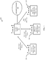
- FIG. 1 is a diagram of an exemplary wireless communications network 100 in accordance with certain aspects of the present disclosure.
- the communication network 100 comprises an access point 102, a backbone network 104, a legacy user device 106, an updated legacy user device 108, and a new protocol user device 110.
- the access point 102 which may be configured for a wireless local area network (LAN) application, may facilitate data communications between the user devices 106, 108, and 110.
- the access point 102 may further facilitate data communications between devices coupled to the backbone network 104 and any one or more of the user devices 106, 108, and 110.
- LAN local area network
- the access point 102 and the legacy user device 106 communicate data between each other using a legacy protocol.
- a legacy protocol includes IEEE 802.11ad.
- data communications between the access point 102 and the legacy user device 106 are effectuated via transmission of data frames that comply with the 802.11ad protocol.
- an 802.11ad data frame includes a preamble consisting of a legacy short training field (L-STF) and a legacy channel estimation sequence (L-CES) (now commonly referred to as a legacy channel estimation field (L-CEF)), a legacy header (L-Header), a data payload, and an optional beamforming training field.
- L-STF legacy short training field
- L-CES legacy channel estimation sequence
- L-Header legacy header
- data payload and an optional beamforming training field.
- the L-STF sequence includes a plurality of Golay sequences (Ga 128 ) and a negative Golay sequence (-Ga 128 ) to signify the end of the L-STF sequence.
- the L-STF sequence may assist a receiver in setting up its automatic gain control (AGC), timing, and frequency setup for accurately receiving the rest of the frame and subsequent frames.
- AGC automatic gain control
- the L-CEF sequence includes a Gu 512 sequence (consisting of the following concatenated Golay sequences (-Gb 128 , -Ga 128 , Gb 128 , -Ga 128 ) followed by a Gv 512 sequence (consisting of the following concatenated Golay sequences (-Gb 128 , Ga 128 , -Gb 128 , -Ga 128 ), and ending with a Gv 128 (same as -Gb 128 ) sequence.
- a Gu 512 sequence consisting of the following concatenated Golay sequences (-Gb 128 , -Ga 128 , Gb 128 , -Ga 128 ) followed by a Gv 512 sequence (consisting of the following concatenated Golay sequences (-Gb 128 , Ga 128 , -Gb 128 , -Ga 128 ), and ending with a Gv 128 (same as
- the L-CEF sequence includes a Gv 512 sequence followed by a Gu 512 sequence, and ending with a Gv 128 sequence.
- the L-CEF sequence assists the receiver in estimating the channel frequency response through which the frame is sent.
- the L-Header includes various information about the frame. Such information includes a scrambler initiation field, which specifies a seed for the scrambling applied to the remainder of the L-Header and the data payload for data whitening purposes.
- the L-Header also includes the modulation and coding scheme (MCS) field to indicate one out of 12 defined MCS used for transmitting the data payload of the frame.
- MCS modulation and coding scheme
- the L-Header includes a length field to indicate the length of the data payload in octets.
- the L-Header further includes a training length field to indicate a length of the optional beam forming training sequence at the end of the frame.
- the L-Header includes a packet type field to indicate whether the optional beam forming field pertains to transmission or reception.
- the L-Header includes a header checksum (HCS) field to indicate a CRC-32 checksum over the header bits.
- HCS header checksum
- the legacy user device 106 is capable of decoding the entire 802.11ad data frame.
- the new frame disclosed herein which may be subsequently adopted for the new standard or protocol 802.11ay, provides some backward compatibility feature.
- the new frame includes the preamble (L-STF and L-CEF) and the L-Header of the 802.11ad protocol, and one or more additional portions pertaining to the new protocol.
- the legacy user device 106 is configured to decode the 802.11ad preamble (L-STF and L-CEF) and L-Header portion of the new frame, but is not configured to decode the remaining portion of the new frame.
- the legacy user device 106 may decode the 802.11ad preamble and header portion of the new frame in order to calculate a network allocation vector (NAV) to determine the length of the new frame for transmission collision avoidance purposes.
- NAV network allocation vector
- the updated legacy user device 108 also operates under the legacy 802.11ad protocol, and is able to communicate with the access point 102 using 802.11ad data frames.
- the frame processing capability of the updated legacy user device 108 has been updated to interpret certain bits in the L-Header of the new frame that indicate an attribute of the new frame, as discussed further herein.
- these bits are allocated to least significant bits (LSBs) of the data length in the L-Header.
- LSBs least significant bits
- the otherwise allocated bits of the L-Header are used to indicate a transmission power difference between a first portion of the new frame and a second portion of the new frame in accordance with a certain transmission mode associated with the new frame.
- These bits allow the updated legacy user device 108 to anticipate the power difference (an increase) for signal interference management purposes.
- the allocation of the LSB length bits signifies the aforementioned power difference, it shall be understood that these bits may be allocated for other purposes.
- the new protocol user device 110 is capable of communicating with the access point 102 using the new data frame, which some or all features of the new frame may be adopted for the 802.11ay protocol.
- the new data frame includes the legacy 802.11ad preamble (L-STF and L-CEF) and L-Header, with the L-Header slightly modified to indicate the transmission mode associated with the new frame and, as previously discussed, a transmission power difference between a first portion of the new frame and a second portion of the new frame.
- the slight modification to the L-Header of the new frame does not impact the decoding of the L-Header by the legacy user device 106 and the updated legacy user device 108.
- the bits in the L-Header of the new frame that indicate the transmission mode are reserved bits in the standard 802.11ad legacy header.
- the new frame further comprises an Extended Directional Multigigabit (EDMG) Header.
- EDMG Extended Directional Multigigabit
- the EDMG Header comprises a plurality of fields for indicating various attributes of the new frame.
- attributes includes payload data length, number of low density parity check (LDPC) data blocks in the EDMG Header, the number of spatial streams supported, the number of bonded channels, the leftmost (lowest frequency) channel of the bonded channels, the MCS used for the data payload of the new frame, the transmit power difference between different portions of the frame, and other information.
- LDPC low density parity check
- the EDMG Header may further be appended with payload data that is not in the data payload portion (now commonly referred to as the EDMG Data Payload) of the new frame. For short messages, all of the payload data may appended to the EDMG Header, thereby avoiding the need for transmitting the "separate" EDMG Data Payload of the new frame, which adds significant overhead to the frame.
- the new data frame is configured to provide additional features to improve data throughput by employing higher data modulation schemes, channel bonding, channel aggregation, and improved spatial transmission via multiple input multiple output (MIMO) antenna configurations.
- the legacy 802.11ad protocol includes BPSK, QPSK, and 16QAM available modulation schemes.
- higher modulation schemes such as 64QAM, 64APSK, 128APSK, 256QAM, and 256APSK are available.
- a plurality of channels may be bonded or aggregated to increase data throughput. Further, such bonded or aggregated channels may be transmitted by way of a plurality of spatial transmissions using a MIMO antenna configuration.
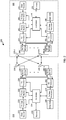
- FIG. 2 illustrates a block diagram of an access point 210 (generally, a first wireless node) and an access terminal 220 (generally, a second wireless node) of the wireless communication system 200.
- the access point 210 is a transmitting entity for the downlink and a receiving entity for the uplink.
- the access terminal 220 is a transmitting entity for the uplink and a receiving entity for the downlink.
- a "transmitting entity” is an independently operated apparatus or wireless node capable of transmitting data via a wireless channel
- a “receiving entity” is an independently operated apparatus or wireless node capable of receiving data via a wireless channel.
- wireless node 210 is an access point and wireless node 220 is an access terminal
- the wireless node 210 may alternatively be an access terminal
- wireless node 220 may alternatively be an access point.
- the wireless node 210 may be used to implement the access point 102 in FIG. 1
- the wireless node 220 may be used to implement any one of the user devices 106, 108 and 110 in FIG. 1 .
- the access point 210 For transmitting data, the access point 210 comprises a transmit data processor 218, a frame builder 222, a transmit processor 224, a plurality of transceivers 226-1 to 226-N, and a plurality of antennas 230-1 to 230-N.
- the access point 210 also comprises a controller 234 configured to control operations of the access point 210, as discussed further below.
- the transmit data processor 218 receives data (e.g., data bits) from a data source 215, and processes the data for transmission. For example, the transmit data processor 218 may encode the data (e.g., data bits) into encoded data, and modulate the encoded data into data symbols.
- the transmit data processor 218 may support different modulation and coding schemes (MCSs). For example, the transmit data processor 218 may encode the data (e.g., using low-density parity check (LDPC) encoding) at any one of a plurality of different coding rates.
- MCSs modulation and coding schemes
- the transmit data processor 218 may modulate the encoded data using any one of a plurality of different modulation schemes, including, but not limited to, BPSK, QPSK, 16QAM, 64QAM, 64APSK, 128APSK, 256QAM, and 256APSK.
- the controller 234 may send a command to the transmit data processor 218 specifying which modulation and coding scheme (MCS) to use (e.g., based on channel conditions of the downlink), and the transmit data processor 218 may encode and modulate data from the data source 215 according to the specified MCS. It is to be appreciated that the transmit data processor 218 may perform additional processing on the data such as data scrambling, and/or other processing. The transmit data processor 218 outputs the data symbols to the frame builder 222.
- MCS modulation and coding scheme
- the frame builder 222 constructs a frame (also referred to as a packet), and inserts the data symbols into a data payload of the frame. Exemplary frame structures or formats are discussed further below.
- the frame builder 222 outputs the frame to the transmit processor 224.
- the transmit processor 224 processes the frame for transmission on the downlink.
- the transmit processor 224 may support different transmission modes such as an orthogonal frequency-division multiplexing (OFDM) transmission mode and a single-carrier (SC) transmission mode.
- the controller 234 may send a command to the transmit processor 224 specifying which transmission mode to use, and the transmit processor 224 may process the frame for transmission according to the specified transmission mode.
- OFDM orthogonal frequency-division multiplexing
- SC single-carrier
- the transmit processor 224 may support multiple-output-multiple-input (MIMO) transmission.
- the access point 210 includes multiple antennas 230-1 to 230-N and multiple transceivers 226-1 to 226-N (e.g., one for each of the antennas 230-1 to 230-N).
- the transmit processor 224 may perform spatial processing on the incoming frames and provide a plurality of transmit frame streams for the plurality of antennas 230-1 to 230-N.
- the transceivers 226-1 to 226-N receive and process (e.g., convert to analog, amplify, filter, and frequency upconvert) the respective transmit frame streams to generate transmit signals for transmission via the antennas 230-1 to 230-N.
- the access terminal 220 For transmitting data, the access terminal 220 comprises a transmit data processor 260, a frame builder 262, a transmit processor 264, a plurality of transceivers 266-1 to 266-N, and a plurality of antennas 270-1 to 270-N.
- the access terminal 220 may transmit data to the access point 210 on the uplink, and/or transmit data to another access terminal (e.g., for peer-to-peer communication).
- the access terminal 220 also comprises a controller 274 configured to control operations of the access terminal 220, as discussed further below.
- the transmit data processor 260 receives data (e.g., data bits) from a data source 255, and processes (e.g., encodes and modulates) the data for transmission.
- the transmit data processor 260 may support different MCSs.
- the transmit data processor 260 may encode the data (e.g., using LDPC encoding) at any one of a plurality of different coding rates, and modulate the encoded data using any one of a plurality of different modulation schemes, including, but not limited to, BPSK, QPSK, 16QAM, 64QAM, 64APSK, 128APSK, 256QAM, and 256APSK.
- the controller 274 may send a command to the transmit data processor 260 specifying which MCS to use (e.g., based on channel conditions of the uplink), and the transmit data processor 260 may encode and modulate data from the data source 255 according to the specified MCS. It is to be appreciated that the transmit data processor 260 may perform additional processing on the data.
- the transmit data processor 260 outputs the data symbols to the frame builder 262.
- the frame builder 262 constructs a frame, and inserts the received data symbols into a data payload of the frame. Exemplary frame structures or formats are discussed further below.
- the frame builder 262 outputs the frame to the transmit processor 264.
- the transmit processor 264 processes the frame for transmission.
- the transmit processor 264 may support different transmission modes such as an OFDM transmission mode and an SC transmission mode.
- the controller 274 may send a command to the transmit processor 264 specifying which transmission mode to use, and the transmit processor 264 may process the frame for transmission according to the specified transmission mode.
- the transmit processor 264 may support multiple-output-multiple-input (MIMO) transmission.
- the access terminal 220 includes multiple antennas 270-1 to 270-N and multiple transceivers 266-1 to 266-N (e.g., one for each of the antennas 270-1 to 270-N).
- the transmit processor 264 may perform spatial processing on the incoming frame and provide a plurality of transmit frame streams for the plurality of antennas 270-1 to 270-N.
- the transceivers 266-1 to 266-N receive and process (e.g., convert to analog, amplify, filter, and frequency upconvert) the respective transmit frame streams to generate transmit signals for transmission via the antennas 270-1 to 270-N.
- the access point 210 For receiving data, the access point 210 comprises a receive processor 242, and a receive data processor 244.
- the transceivers 226-1 to 226-N receive signals (e.g., from the access terminal 220) via the antennas 230-1 to 230-N, and process (e.g., frequency downconvert, amplify, filter, and convert to digital) the received signals.
- the receive processor 242 receives the outputs of the transceivers 226-1 to 226-N, and processes the outputs to recover data symbols.
- the access point 210 may receive data (e.g., from the access terminal 220) in a frame.
- the receive processor 242 may detect the start of the frame using the STF sequence in the preamble of the frame.
- the receive processor 242 may also use the STF for automatic gain control (AGC) adjustment.
- AGC automatic gain control
- the receive processor 242 may also perform channel estimation (e.g., using the CEF in the preamble of the frame) and perform channel equalization on the received signal based on the channel estimation.
- the receive processor 242 may also recover information (e.g., MCS scheme) from the header of the frame, and send the information to the controller 234. After performing channel equalization, the receive processor 242 may recover data symbols from the frame, and output the recovered data symbols to the receive data processor 244 for further processing. It is to be appreciated that the receive processor 242 may perform other processing.
- MCS scheme e.g., MCS scheme
- the receive data processor 244 receives the data symbols from the receive processor 242 and an indication of the corresponding MCS scheme from the controller 234.
- the receive data processor 244 demodulates and decodes the data symbols to recover the data according to the indicated MCS scheme, and outputs the recovered data (e.g., data bits) to a data sink 246 for storage and/or further processing.
- the access terminal 220 may transmit data using an OFDM transmission mode or a SC transmission mode.
- the receive processor 242 may process the receive signal according to the selected transmission mode.
- the transmit processor 264 may support multiple-output-multiple-input (MIMO) transmission.
- the access point 210 includes multiple antennas 230-1 to 230-N and multiple transceivers 226-1 to 226-N (e.g., one for each of the antennas 230-1 to 230-N).
- Each of the transceivers 226-1 to 226-N receives and processes (e.g., frequency downconverts, amplifies, filters, converts to digital) the signal from the respective antenna.
- the receive processor 242 may perform spatial processing on the outputs of the transceivers 226-1 to 226-N to recover the data symbols.
- the access terminal 220 For receiving data, the access terminal 220 comprises a receive processor 282, and a receive data processor 284.
- the transceivers 266-1 to 266-N receive signals (e.g., from the access point 210 or another access terminal) via the antennas 270-1 to 270-3, and process (e.g., frequency downconvert, amplify, filter, and convert to digital) the received signals.
- the receive processor 282 receives the outputs of the transceivers 266-1 to 226-N, and processes the outputs to recover data symbols.
- the access terminal 220 may receive data (e.g., from the access point 210 or another access terminal) in a frame, as discussed above.
- the receive processor 282 may detect the start of the frame using the STF sequence in the preamble of the frame.
- the receive processor 282 may also perform channel estimation (e.g., using the CEF in the preamble of the frame) and perform channel equalization on the received signal based on the channel estimation.
- the receive processor 282 may also recover information (e.g., MCS scheme) from the header of the frame, and send the information to the controller 274. After performing channel equalization, the receive processor 282 may recover data symbols from the frame, and output the recovered data symbols to the receive data processor 284 for further processing. It is to be appreciated that the receive processor 282 may perform other processing.
- information e.g., MCS scheme
- the receive data processor 284 receives the data symbols from the receive processor 282 and an indication of the corresponding MCS scheme from the controller 274.
- the receive data processor 284 demodulates and decodes the data symbols to recover the data according to the indicated MCS scheme, and outputs the recovered data (e.g., data bits) to a data sink 286 for storage and/or further processing.
- the access point 210 or another access terminal may transmit data using an OFDM transmission mode or a SC transmission mode.
- the receive processor 282 may process the receive signal according to the selected transmission mode.
- the transmit processor 224 may support multiple-output-multiple-input (MIMO) transmission.
- the access terminal 220 includes multiple antennas 270-1 to 270-N and multiple transceivers 266-1 to 266-N (e.g., one for each the antennas 270-1 to 270-N).
- Each of the transceivers 266-1 to 266-N receives and processes (e.g., frequency downconverts, amplifies, filters, and converts to digital) the signal from the respective antenna.
- the receive processor 282 may perform spatial processing on the outputs of the transceivers 266-1 to 266-N to recover the data symbols.
- the access point 210 also comprises a memory 236 coupled to the controller 234.
- the memory 236 may store instructions that, when executed by the controller 234, cause the controller 234 to perform one or more of the operations described herein.
- the access terminal 220 also comprises a memory 276 coupled to the controller 274.
- the memory 276 may store instructions that, when executed by the controller 274, cause the controller 274 to perform the one or more of the operations described herein.
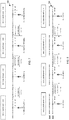
- FIGS. 3A-3D show exemplary frames 300, 310, 320, and 330 in accordance with certain aspects of the present disclosure.
- Each of the frames 300, 310, 320, and 330 comprises a legacy short training field (L-STF), a legacy channel estimation field (CEF), and a legacy header (L-Header).
- L-STF legacy short training field
- CEF legacy channel estimation field
- L-Header legacy header
- the L-STF, L-CEF, and L-Header can be decoded by a receiving device (e.g., user device 106) operating under a legacy protocol, such as IEEE 802.11ad.
- a legacy device may decode the 802.11ad preamble (L-STF and L-CEF) and header portion (L-Header) of each of the new frames 300, 310, 320, and 330 in order to calculate a network allocation vector (NAV) to determine the length of the new frame for transmission collision avoidance purposes.
- L-STF and L-CEF 802.11ad preamble
- L-Header header portion
- NAV network allocation vector
- Each of the exemplary frames 300, 310, 320, and 330 further comprises an Extended Directional Multigigabit (EDMG) Header, which may have attached data.
- EDMG Header provides information concerning the new frames 300, 310, 320, and 330. Additionally, some or the entire data payload may be attached to the EDMG Header, as discussed above.
- the EDMG Header may include: (1) a data payload length of the frame; (2) number of LDPC data blocks attached to the EDMG Header of the frame; (3) number of spatial streams transmitted in the frame; (4) the number of bonded channels in the frame; (5) the channel offset indicating the first (lowest frequency) channel of the bonded channels; (6) the MCS used for the data in the 802.11ay data payload; (7) the length (short, normal, or long) of the guard interval (GI) in each data (FFT) block in the 802.11ay data payload; (8) the length (short or long) of the data (FFT) block in the 11ay data payload; (9) the length (short or long) of the encoded (LDPC) block(s) in the data (FFT) block in the 11ay data payload; (10) a long CEF field to signal a long 802.11ay CEF sequence for MIMO; (11) a power difference field to indicate a power difference between the L-STF, L
- Each of the new frames 310, 320, and 330 includes an 802.11ay portion that may include three (3) sections: an EDMG STF (also referred to as NG60 STF), an EDMG CEF (also referred to as NG60 CES), and a EDMG Data Payload.
- the 802.11ay portion may also include an optional beam training sequence (TRN).
- the EDMG STF may be built using Golay codes (as in the legacy STF). During this period, a receiver is expected to complete the following: automatic gain control (AGC), timing and frequency acquisition.
- AGC automatic gain control
- the EDMG STF may use Ga and Gb in the same order as the 802.11ad.
- the Golay codes can be 128 (as in 802.11ad) or 256 or 512 in length.
- the EDMG CEF may also be built using the same Golay construction as the L-CEF sequence of 802.11ad, only replacing the 128 sequences with 256 sequences for double channel, 512 sequences for triple and quad channels, and 1024 for 5-8 channels.
- the EDMG Data Payload may be modulated and encoded using MCSs similar to the 802.11ad protocol with the following changes: (1) in addition to BPSK, QPSK and 16QAM, higher modulations are defined (and can be used): 64QAM, 64APSK, 128APSK, 256QAM, and 256APSK; (2) data symbol (FFT) block can be 512 (as in 802.11ad) or 1024, 1536 or 2048; and (3) guard interval (GI) may also be Golay code as in 802.11ad, with more length options supported: 64 (as in 802.11ad), 32, 96, 128, 192, 256, 384, or 512.
- MCSs similar to the 802.11ad protocol with the following changes: (1) in addition to BPSK, QPSK and 16QAM, higher modulations are defined (and can be used): 64QAM, 64APSK, 128APSK, 256QAM, and 256APSK; (2) data symbol (FFT) block can
- the exemplary frame 300 shown in FIG. 3A is the extension of 802.11ay for a single channel case.
- the frame 300 comprises the legacy preamble (L-STF and L-CEF), legacy Header (L-Header), and new EDMG Header.
- the frame 300 facilitates the new MCSs of the 802.11ay protocol with the transmission of the 802.11ay STF (EDMG STF) and Data Payload.
- EDMG CEF 802.11ay CEF
- the EDMG STF is present since a receiver may improve the receiver chain setup for higher constellations of the 802.11ay modulation.
- the exemplary frame 310 shown in FIG. 3B is the extension of 802.11ay for a two channel bonding case.
- the frame 310 comprises a first (legacy) channel (e.g., CH1) for transmitting the legacy preamble (L-STF and L-CEF), L-Header, and EDMG Header.
- the frame 310 further comprises a second (legacy) channel (e.g., CH2) for transmitting the legacy preamble (L-STF and L-CEF), L-Header, and EDMG Header.
- the attached data following the EDMG Header of the first channel (CH1) may be different than the attached data following the EDMG Header of the second channel (CH2).
- the information fields of the EDMG Header may be configured as per EDMG Header format previously discussed.
- the 802.11ay portion of the frame 310 namely the EDMG STF, EDMG CEF, EDMG Data Payload, and optional TRN, are transmitted via a bonded channel comprising at least a portion of each of the first and second channels (e.g., CH1+CH2).
- the transmission of the L-STF AND L-CEF, L-Header, and EDMG Header uses an MCS specified in legacy 802.11ad
- the transmission of the 802.11ay portion uses an MCS specified in 802.11ay, which may be different from the MCS specified in legacy 802.11ad.
- the exemplary frame 320 shown in FIG. 3C is the extension of 802.11ay frame for a three (3) channel bonding case (e.g., CH1+CH2+CH3).
- the exemplary frame 330 shown in FIG. 3D is the extension of 802.11ay frame for the four (4) channel bonding case (e.g., CH1+CH2+CH3+CH4). From FIGS. 3A-3D , it is clear that the frame format is extendable to any number of channels (e.g., five, six or seven channels).
- FIG. 3E illustrates an exemplary transmission power profile for any of the exemplary frames 300, 310, 320, and 330 in accordance with certain aspects of the disclosure.
- the transmit power for the L-STF, L-CEF, L-Header, and EDMG Header (with attached data) of the aggregate channels is backed off to reduce peak to average power ratio (PAPR).
- the transmit power for the 802.11ay portion (EDMG STF, EDMG CEF, and Data Payload) is increased for better detection at a receiver.
- the power difference may be indicated in the EDMG Header.
- the L-Header may also be modified to include information indicating the power difference. For example, this information may be included in least significant bits (LSBs) of the data length field of the L-Header, and/or in the reserved bit field of the L-Header.
- LSBs least significant bits
- the vertical dashed line extending from the transmission power profile in FIG. 3E indicates the transition between the different power levels according to certain aspects of the present disclosure.
- the transmit power for the L-STF, L-CEF, L-Header, and EDMG Header (with attached data) of each frame is lower than the transmit power for the 802.11ay portion (EDMG STF, EDMG CEF, and Data Payload).
- the portion of each frame to the left of the dashed line may be transmitted using SC transmission mode for each channel. This may be done for backwards compatibility with legacy devices.
- the portion of each frame to the right of the dashed line (802.11ay portion) may be transmitted using ODFM transmission mode.
- the exemplary frames 310, 320 and 330 may be extended to support single user MIMIO (SU-MIMO) and multiple user MIMO (MU-MIMO).
- SU-MIMO single user MIMIO
- MU-MIMO multiple user MIMO
- the EDMG STF and EDMG CEF may be different and an additional header (referred to as EDMG Header-B) may be added to support MIMO.
- EDMG Header-B additional header
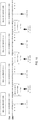
- FIGS. 4A-4C illustrate exemplary frames 410, 420, and 430 for transmission on non-adjacent (non-contiguous) channels in accordance with certain aspects of the disclosure.
- Each of the frames 410, 420 and 430 may maintain the legacy 802.11ad preamble (L-STF and L-CEF) and L-Header as prefix in order to be backwards compliant.
- the legacy 802.11ad preamble (L-STF and L-CEF) and L-Header may be transmitted with some backoff to reduce peak to average power ratio (PARP), as discussed further below.
- PARP peak to average power ratio
- frame 410 is an example of a two channel aggregate (non-adjacent) frame in accordance with the proposed new protocol (802.11ay).
- Transmission of the frame 410 comprises a first channel (CH1) transmission including the L-STF, the L-CEF, the L-Header, the EDMG Header with the optional attached data, the EDMG STF, the EDMG CEF, the Data Payload, and optional TRN.
- the first channel (CH1) may have a bandwidth of substantially 1.76 GHz.
- Transmission of the frame 410 further comprises a third channel (CH3) transmission including the L-STF, the L-CEF, the L-Header, the EDMG Header with the optional attached data, the EDMG STF, the EDMG CEF, the Data Payload, and optional TRN.
- the transmission of the legacy preamble and header in the first and third channels (CH1 and CH3) are for 802.11ad backward compatibility.
- the data attached to the EDMG Header for the first channel (CH1) may be different than the data attached to the EDMG Header of the third channel (CH3).
- the third channel (CH3) may also have a bandwidth of 1.76 GHz.
- Frame 410 does not include transmissions via channels CH2 and CH4.
- Frame 420 is an example of a two channel aggregate (non-adjacent) frame in accordance with the proposed new protocol (802.11ay). Similar to frame 410, transmission of the frame 420 comprises a first channel (CH1) transmission including the L-STF, the L-CEF, the L-Header, the EDMG Header with the optional attached data, the EDMG STF, the EDMG CEF, the Data Payload, and optional TRN. The transmission of the frame 420 further comprises a fourth channel (CH4) transmission including the L-STF, the L-CEF, the L-Header, the EDMG Header with the optional attached data, the EDMG STF, the EDMG CEF, the Data Payload, and optional TRN. Frame 420 does not include transmissions via channels CH2 and CH3.
- Frame 430 is an example of a two channel aggregate (non-adjacent) frame in accordance with the proposed new protocol (802.11ay).
- Transmission of the frame 430 comprises a second channel (CH2) transmission including the L-STF, the L-CEF, the L-Header, the EDMG Header with the optional attached data, the EDMG STF, the EDMG CEF, the Data Payload, and optional TRN.
- Transmission of the frame 430 further comprises a fourth channel (CH4) transmission including the L-STF, the L-CEF, the L-Header, the EDMG Header with the optional attached data, the EDMG STF, the EDMG CEF, the Data Payload, and optional TRN.
- Frame 430 does not include transmissions via channels CH1 and CH3.
- FIG. 4D illustrates an exemplary transmission power profile for any of the exemplary frames 410, 420 and 430 in accordance with certain aspects of the disclosure.
- the transmit power for the L-STF, L-CEF, L-Header, and EDMG Header (with attached data) of the aggregate channels is backed off to reduce peak to average power ratio (PAPR).
- the transmit power for the 802.11ay portion (EDMG STF, EDMG CEF, and Data Payload) is increased for better detection at a receiver.
- the vertical dashed line extending from the transmission power profile in FIG. 4D indicates the transition between the different power levels according to certain aspects of the present disclosure. In this example, the transmit power to the left of the dashed line is lower than the transmit power to the right of the dashed line.
- FIGS. 4E and 4F illustrate additional exemplary frames 440 and 450 according to certain aspects of the present disclosure.
- Each of these frames 440 and 450 includes a transmission via a bonded channel and a non-adjacent single channel.
- transmission of the frame 440 includes a first transmission via non-adjacent single channel CH1, and a second transmission via a bonded channel CH3+CH4.
- Transmission of the frame 440 includes time-aligned transmission of the legacy portion (L-STF, L-CEF, and L-Header) and the EDMG Header via separate channels CH3 and CH4.
- the transmission of the frame 440 also includes transmission of the EDMG STF, EDMG CEF, and Data Payload via frequency bonded channels CH3+CH4.
- Transmission of frame 450 includes a first transmission via a bonded channel CH1+CH2, and a second transmission via a single non-adjacent channel CH4. In this example, there is no transmission via channel CH3.
- the transmission of the frame 450 includes time-aligned transmission of the legacy portion (L-STF, L-CEF, and L-Header) and the EDMG Header via separate channels CH1 and CH2.
- the transmission of the frame 450 also includes transmission of the EDMG STF, EDMG CEF, and Data Payload via frequency bonded channels CH1+CH2.
- FIG. 4G illustrates an exemplary transmission power profile for any of the exemplary frames 440 and 450 in accordance with certain aspects of the disclosure.
- the transmit power for the L-STF, L-CEF, L-Header, and EDMG Header (with attached data) of the aggregate channels is backed off to reduce peak to average power ratio (PAPR).
- the transmit power for the 802.11ay portion (EDMG STF, EDMG CEF, and Data Payload) is increased for better detection at a receiver.
- the vertical dashed line extending from the transmission power profile in FIG. 4G indicates the transition between the different power levels according to certain aspects of the present disclosure. In this example, the transmit power to the left of the dashed line is lower than the transmit power to the right of the dashed line.
- the IEEE 802.11ad standard defines four channels and two transmission modes with one being the OFDM transmission mode discussed above.
- the OFDM sampling rate is 2.64GHz using a Fast Fourier Transform (FFT) of 512.
- FFT Fast Fourier Transform
- the OFDM sub-carriers are spaced 5.15625MHz (2.64GHz/512) apart, with one of the sub-carriers being exactly at the channel center frequency.
- FIG. 5 shows the sub-carriers for one of the channels 500 according to the 802.11ad standard.
- the horizontal axis in FIG. 5 corresponds to frequency and the spacing of the OFDM sub-carriers is denoted by ⁇ F.
- ⁇ F the spacing of the OFDM sub-carriers
- one of the sub-carriers is located at the center frequency (CF) of the channel 500.
- the sub-carrier at the center frequency of the channel 500 is represented by a rectangle and the other sub-carriers of the channel 500 are represented by ovals. Further details may be found, for example, in IEEE P802.11ad/D9.0, July 2012, sections 21.3.4 and 21.5.3.2.6.
- FIG. 6 shows the sub-carriers for all four channels 600 according to the 802.11ad standard, where the horizontal axis corresponds to frequency.
- the sub-carrier at the center frequency of each channel is represented by a rectangle, and the other sub-carriers of each channel are represented by ovals.
- the channel spacing is 2.16GHz (i.e., spacing between the center frequencies of two adjacent channels).
- channel-bonding will be used to increase the link throughput, as discussed above.
- the fact that the channel spacing is a non-integer multiple of the sub-carrier spacing limits the ability to process two or more channels with a single Fast Fourier Transform (FFT).
- FFT Fast Fourier Transform
- the frequency grid may comprise a plurality of evenly spaced frequency positions, in which each sub-carrier is aligned with a respective one of the frequency positions on the grid.
- FIG. 7 shows an exemplary frequency grid 700 for all channels (four channels in this example).
- the frequency grid 700 comprises evenly spaced frequency positions (spaced apart by the sub-carrier spacing, which may be 5.15625MHz).
- the sub-carriers for each channel are aligned with respective frequency positions on the frequency grid 700.
- the center frequencies of the channels are: 58319.53125, 60480, 62640.46875 and 64800.9375MHz, although it is to be appreciated that the present disclosure is not limited to this example.
- the spacing between the edge sub-carriers of two adjacent channels is an integer multiple of the sub-carrier spacing (65 in the example in FIG. 7 ).
- additional sub-carriers in the gaps between the channels may be also aligned with respective frequency positions on the frequency grid 700. This allows the sub-carriers of a bonded channel (which may comprise two or more of the channels and one or more of the gaps shown in FIG.
- the sub-carrier at the center frequency of each channel is represented by a rectangle, and the other sub-carriers of each channel are represented by ovals.
- the sub-carrier frequencies may be redefined only for the 802.11ay portion of the frame (e.g., EDMG STF, EDMG CEF and Data Pay Load).
- the legacy portion of an 802.11ay frame e.g., any one of the frames in FIGS. 3A-3D , 4A-4C , 4E and 4F
- a transmitter may transmit a legacy portion of an 802.11ay frame using the legacy channel center frequencies.
- the transmitter may then perform a small frequency shift according to its center frequency (e.g., dependent on channel and channel bonding) to transmit the 802.11ay portion using the redefined channel center frequencies and sub-carrier frequencies (e.g., shown in FIG. 7 ).
- a receiver may receive the legacy portion of an 802.11ay frame using the legacy channel center frequencies.
- the receiver may then perform a small frequency shift according to its center frequency (e.g., dependent on channel and channel bonding) to receive the 802.11ay portion using the redefined channel center frequencies and sub-carrier frequencies.
- the frequency shift (change) may be performed on the received signal by a small rotation unit that most receivers already have for frequency correction (e.g., to correct for carrier frequency offset between the transmitter and the receiver).
- the frequency shift may have little or no hardware impact.
- the frequency shift may be bounded by 1 ⁇ 2 of a sub-carrier spacing ( ⁇ 2.5MHz) or less than 1MHz in certain embodiments, as discussed further below. Thus, the frequency shift may be small.
- FIG. 8 shows the legacy sub-carrier frequencies (top row) and an example of redefined sub-carrier frequency frequencies (bottom row).
- FIG. 8 also shows the legacy channel center frequencies: 58.32, 60.48, 62.64 and 64.80GHz.
- a receiver may receive a first portion of an 802.11ay frame using the legacy channel center frequencies.
- the first portion of the frame may include L-STF, L-CEF, L-Header and EDMG Header.
- the receiver may then perform a frequency shift to receive a second portion of the 802.11ay frame using the redefined channel center frequencies and sub-carrier frequencies.
- the second portion of the frame may include the EDMG STF, EDMG CEF and Data Payload.
- the sub-carrier at the center frequency of each channel is represented by a rectangle, and the other sub-carriers of each channel are represented by ovals. As shown in FIG. 8 , the required frequency shift is small.
- the legacy 802.11ad subcarriers for each channel are located at: CFi + (-177...177)* 5.15625MHz, where CFi is the center frequency of the channel.
- CFi is the center frequency of the channel.
- the subcarriers frequencies are: 57.40734375, 57.4125...59.2275, 59.23265625GHz.
- the legacy center frequency for CH2 is kept in place for simplicity, while the center frequencies of the other channels are redefined (although it is to be appreciated that the center frequency of another one of the channels may be kept in place instead). This may be accomplished by aligning one of the frequency positions of the frequency grid 700 with the legacy center frequency for CH2 (an example of which is shown in FIG. 8 ). This option results in a max frequency shift of less than 1MHz over the entire band.
- the new center frequencies for CH1, CH3 and CH4 for OFDM are computed by offsets of -419, 419 and 2*419 SCS from the CH2 center frequency, where SCS is a sub-carrier spacing.
- the center frequencies of all channels are: 58319.53125, 60480, 62640.46875 and 64800.9375 MHz.
- SCS sub-carrier spacing
- the OFDM sub-carrier indexes (denote by i) for each channel are: -177... 177.
- the sub-carrier frequencies (Fi) for the four channels are as follows:
- FIG. 8 shows an example of re-channelization using the above example.
- the 802.11ad sub-carrier frequencies (top row) are also shown for reference. All of the sub-carriers on the 802.11ay row (bottom row), including the sub-carriers in the gaps between the channels, are evenly spaced by ⁇ F. Note that all sub-carriers except those in CH2 are not aligned with the 802.11ad sub-carriers, and the CFs are not aligned to any 802.11ad sub-carrier (except CH2 which is by design in this example).
- the present disclosure may be extended to additional channels.
- the frequency grid 700 may be extended to five, six, seven or more channels.
- the sub-carrier frequencies (Fi) for additional channels may be given as follows:
- the offset between the center frequencies of the channels is 418 instead of 419.
- the sub-carrier frequencies (Fi) for the four channels in this example are as follows:
- FIG. 9 shows an example of re-channelization using the above example.
- the 802.11ad sub-carrier frequencies (top row) are also shown for reference. All of the sub-carriers on the 802.11ay row (bottom row), including the sub-carriers in the gaps between the channels, are evenly spaced by ⁇ F.
- the sub-carrier at the center frequency of each channel is represented by a rectangle, and the other sub-carriers of each channel are represented by ovals.
- the center frequencies for channels CH1, CH3 and CH4 on 802.11ay are shifted inward relative to the center frequencies for channels CH1, CH3 and CH4 on 802.11ad.
- the center frequency for CH2 on 802.11ay is aligned with the center frequency for CH2 on 802.11ad, although it is to be appreciated that this need not be the case.
- the maximum frequency shift may be less than 2*SCS.
- the present disclosure may be extended to additional channels.
- the frequency grid 700 may be extended to five, six, seven or more channels.
- the sub-carrier frequencies (Fi) for additional channels may be given as follows:
- the offset between the center frequencies of the channels is 420 instead of 419.
- the sub-carrier frequencies (Fi) for the four channels in this example are as follows:
- FIG. 10 shows an example of re-channelization using the above example.
- the 802.11ad sub-carrier frequencies (top row) are also shown for reference. All the sub-carriers on the 802.11ay row (bottom row), including the sub-carriers in the gaps between the channels, are evenly spaced by ⁇ F.
- the sub-carrier at the center frequency of each channel is represented by a rectangle, and the other sub-carriers of each channel are represented by ovals.
- the center frequencies for channels CH1, CH3 and CH4 on 802.11ay are shifted outward relative to the center frequencies for channels CH1, CH3 and CH4 on 802.11ad.
- the center frequency for CH2 on 802.11ay is aligned with the center frequency for CH2 on 802.11ad, although it is to be appreciated that this need not be the case.
- the maximum frequency shift may be less than 3*SCS.
- the present disclosure may be extended to additional channels.
- the frequency grid 700 may be extended to five, six, seven or more channels.
- the sub-carrier frequencies (Fi) for additional channels may be given as follows:
- FIG. 11 shows an example of different channel bonding (CB) options, in which each row corresponds to a different CB option.
- CB channel bonding
- the top row 1110 shows an example where all four channels are bonded.
- the center rows 1120 show examples where three channels are bonded, and the bottom rows 1130 show examples where two channel are bonded.
- the gaps for OFDM sub-carriers in the suggested case 64 sub-carriers are added per gap).
- the numbering of the sub-carriers in CB modes can be similar to the existing numbering scheme (0 is the center per CB option) or global (one indexing for all channel regardless of CF or CB). This has no impact on the re-channelization.
- FIG. 11 also shows the redefined channel center frequencies and sub-carrier frequencies according to the example discussed above.
- the redefined channel center frequencies and sub-carrier frequencies may be used for any of the CB options.
- the redefined sub-carrier frequencies for channels CH1, CH2 and CH3 may be used as well as the additional sub-carrier frequencies in the gap between CH1 and CH2 and the gap between CH2 and CH3.
- the sub-carrier frequencies for CH2 are the same as the legacy sub-carrier frequencies for CH2 by design (although this need not be the case).
- the redefined sub-carrier frequencies for channels CH3 and CH4 may be used as well as the additional sub-carrier frequencies in the gap between CH3 and CH4.
- the frequency grid 700 is aligned with the legacy center frequency for channel CH2 in FIG. 11 for simplicity, it is to be appreciated that the present disclosure is not limited to this example.
- the frequency grid 700 may be aligned with the legacy center frequency of any one of the other channels (i.e., CH1, CH3 or CH4).
- the frequency grid 700 may not be aligned with the legacy center frequency of any of the channels.
- the sub-carriers of each channel and the additional subcarriers in the gaps may be aligned with respective frequency positions of the frequency grid, in which the frequency positions of the grid are evenly spaced (e.g., by a sub-carrier spacing).
- FIG. 12 shows the different channel bonding (CB) options and exemplary center frequencies for the different CB options, as discussed further below.
- the center frequencies may be: 59399.765625MHz (CH1+CH2), 61560.234375MHz (CH2+CH3), and 63720.703125MHz (CH3+CH4).
- the center frequencies may be: 60480MHz (CH1+CH2+CH3) and 62640.46875 MHz (CH2+CH3+CH4).
- the center frequency may be 61560.234375 MHz.
- center frequencies discussed above correspond to channel center frequencies in 802.11ad. Center frequencies that are only used in 802.11ay in the examples discussed above are indicated as "ay only" in FIG. 12 .
- the legacy center frequency for the channel may be used, as shown in FIG. 12 .
- each of the CB options shown in the example in FIG. 12 may use a frequency grid that is aligned with the respective center frequency (i.e., a frequency position of the grid is aligned with the respective center frequency).
- the frequency positions of each grid may be evenly spaced (e.g., by a sub-carrier spacing).
- the receiver may know in advance which CB option is being used, and therefore which grid to use (e.g., to receive the 802.11ay portion of a frame).
- the transmitter may transmit an indicator to the receiver indicating which CB option is being used (e.g., prior to transmission of the 802.11ay portion).
- the indicator may be transmitted before the frame and/or included in a header in the EDMG of the frame.
- the legacy channel center frequencies may be used to transmit or receive a first portion of the frame (which may include L-STF, L-CEF, L-Header and EDMG Header) on one or more of the channels.
- the transmitter or receiver may then perform a frequency shift according to its center frequency to transmit or receive a second portion of the 802.11ay frame using the redefined channel center frequencies and sub-carrier frequencies.
- the second portion of the frame may include the 802.11ay EDMG Data Payload (which may also be referred to as NG60 payload).
- the second portion may also include the EDMG STF and EDMG CEF.
- the frequency may be changed before the 802.11ay portion of a frame (e.g., after the EDMG Header and attached data).
- the change should be synchronized with the start of STF, or CEF or Payload GI (guard interval) of the 802.11ay portion (whichever is first).
- Examples of frames comprising STF and CEF in the 802.11ay portion can be found, for example, in U.S. Provisional Application No. 62/147,479 , filed on April 29, 2015, titled "Frame Format for OFDM, SC WB, Aggregated SC, and Corresponding MIMO signals,".
- the transmitter should include a frequency rotator (if it is not already included) for the shift (change).
- the range for the shift may be -/+ sub-carrier spacing divided by two (e.g., -2.578125MHz... +2.578125MHz) or smaller.
- the frequency shift may be synchronized as stated above.
- the receiver may be tuned to one of the four channels or in the middle of two adjacent channels (as presented above), and can receive the legacy portion (e.g., L-STF, L-CEF and L-Header) and EDMG Header.
- the legacy portion e.g., L-STF, L-CEF and L-Header
- the receiver may lock the frequency correction.
- the receiver should update the frequency rotator frequency offset to compensate for the OFDM shift.
- the receiver should compensate the frequency shift of the CEF (if L-CEF is used) relative to the OFDM center bin. This operation is easy since the CEF is performed by Golay correlator that estimates the channel (CE) in time domain.
- the CE Before the CE is converted to frequency domain, the CE can be shifted by a phasor that rotates at the frequency to be shifted. If CE is performed on 802.11ay CEF then there is no need for compensation since CEF will be transmitted according to the shifted frequency.
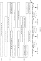
- FIG. 13 is a flowchart illustrating a method 1300 for wireless communication according to aspects of the present disclosure.
- the method 1300 may be performed by a transmitter in a wireless node.
- a frame is generated comprising a first portion and a second portion.
- the frame may be generated by the frame builder 222 or 226 of a wireless node (e.g., access point 210 or access terminal 220).
- the frame may be an 802.11ay frame.
- the first portion may comprise an L-STF, L-CEF, L-Header and EDMG Header
- the second portion may comprise a payload (e.g., EDMG Data Payload).
- the second portion may also include an EDMG STF and an EDMG CEF.
- the first portion of the frame is output for transmission on the at least one channel.
- the first portion e.g., 802.11ad portion
- the legacy channel center frequency discussed above.
- a center frequency of the at least one channel is shifted.
- the center frequency may be shifted from a legacy channel center frequency (e.g., shown in FIG. 6 ) to a redefined channel center frequency (e.g., shown in FIG. 7 ).
- the second portion of the frame is output for transmission on the at least one channel after the center frequency shift.
- the second portion e.g., 802.11ay portion
- FIG. 14 is a flowchart illustrating a method 1400 for wireless communication according to aspects of the present disclosure.
- the method 1400 may be performed by a receiver in a wireless node.
- a first portion of a frame is received, via a receiver, on at least one channel.
- the frame may be an 802.11ay frame, and the first portion may comprise an L-STF, L-CEF, L-Header and EDMG Header.
- a frequency of the receiver is shifted if a shift in a center frequency of the at least one channel is shifted.
- the frequency of the receiver may be shifted using a rotation unit in a receive path of the receiver used for frequency correction, as discussed above.
- the shift in the center frequency of the at least one channel be may be a shift from a legacy channel center frequency (e.g., shown in FIG. 6 ) to a redefined channel center frequency (e.g., shown in FIG. 7 ).
- step 1430 after the receiver frequency shift, a second portion of the frame is received, via the receiver on the at least one channel.
- the received first portion is processed to obtain first information.
- the first information may comprise frame timing information (e.g., using L-STF in the first portion), a channel estimation (e.g., using L-CEF in the first portion), header information (e.g., using L-Header in the first portion), etc.
- the received second portion is processed to obtain second information.
- the second information may comprise data (e.g., EDMG Payload).
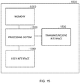
- FIG. 15 illustrates an example device 1500 according to certain aspects of the present disclosure.
- the device 1500 may be configured to operate in a wireless node (e.g., access point 210 or access terminal 220) and to perform one or more of the operations described herein.
- the device 1500 includes a processing system 1520, and a memory 1510 coupled to the processor system 1520.
- the memory 1510 may store instructions that, when executed by the processing system 1520, cause the processing system 1520 to perform one or more of the operations described herein. Exemplary implementations of the processing system 1520 are provided below.
- the device 1500 also comprises a transmit/receiver interface 1530 coupled to the processing system 1520.
- the interface 1530 (e.g., interface bus) may be configured to interface the processing system 1520 to a radio frequency (RF) front end (e.g., transceivers 226-1 to 226-N or 226-1 to 266-N).
- RF radio frequency
- the processing system 1520 may include one or more of the following: a transmit data processor (e.g., transmit data processor 218 or 260), a frame builder (e.g., frame builder 222 or 262), a transmit processor (e.g., transmit processor 224 or 264) and/or a controller (e.g., controller 234 or 274) for performing one or more of the operations described herein.
- a transmit data processor e.g., transmit data processor 218 or 260
- a frame builder e.g., frame builder 222 or 262
- a transmit processor e.g., transmit processor 224 or 26
- controller e.g., controller 234 or 274
- the device 1500 may include a user interface 1540 coupled to the processing system 1520.
- the user interface 1540 may be configured to receive data from a user (e.g., via keypad, mouse, joystick, etc.) and provide the data to the processing system 1520.
- the user interface 1540 may also be configured to output data from the processing system 1520 to the user (e.g., via a display, speaker, etc.). In this case, the data may undergo additional processing before being output to the user.
- the user interface 1540 may be omitted.
- Examples of means for generating a frame comprising a first portion and a second portion include the frame builder 222 or 262, the transmit data processor 218 or 260, the controller 234 or 274, and the processing system 1520.
- Examples of means for outputting the first portion of the frame for transmission on at least one channel include the transmit processor 224 or 264, the transceivers 226-1 to 226-N or 266-1 to 266-N, and the transmit/receive interface 1530.
- Examples of means for shifting a center frequency of the at least one channel include the transmit processor 224 or 264, the transceivers 226-1 to 226-N or 266-1 to 266-N, the controller 234 or 274, the processing system 1520, and the transmit/receive interface 1530.
- Examples of means for outputting the second portion of the frame for transmission on the at least one channel after the center frequency shift include the transmit processor 224 or 264, the transceivers 226-1 to 226-N or 266-1 to 266-N, and the transmit/receive interface 1530.
- Examples of means for receiving a first portion of a frame on at least one channel include the transceivers 226-1 to 226-N or 266-1 to 266-N, the receive processor 242 or 282, and the transmit/receive interface 1530.
- Examples of means for shifting a receiver frequency of the apparatus if a center frequency of the at least one channel is shifted include the transceivers 226-1 to 226-N or 266-1 to 266-N, the receive processor 242 or 282, the controller 234 or 274, the processing system 1520, and the transmit/receive interface 1530.
- Examples of means for receiving, after the receiver frequency shift, a second portion of the frame on the at least one channel include the transceivers 226-1 to 226-N or 266-1 to 266-N, the receive processor 242 or 282, and the transmit/receive interface 1530.
- Examples of means for processing the received first portion of the frame to obtain first information include the receive processor 242 or 282, the receive data processor 244 or 284, the controller 234 or 274, and the processing system 1520.
- Examples of means for processing the received second portion of the frame to obtain second information include the receive processor 242 or 282, the receive data processor 244 or 284, the controller 234 or 274, and the processing system 1520.
- the various operations of methods described above may be performed by any suitable means capable of performing the corresponding functions.
- the means may include various hardware and/or software component(s) and/or module(s), including, but not limited to a circuit, an application specific integrated circuit (ASIC), or processor.
- ASIC application specific integrated circuit
- a device may have an interface to output a frame for transmission (a means for outputting). For example, a processor may output a frame, via a bus interface, to a radio frequency (RF) front end for transmission.
- RF radio frequency
- a device may have an interface to obtain a frame received from another device (a means for obtaining). For example, a processor may obtain (or receive) a frame, via a bus interface, from an RF front end for reception.
- determining encompasses a wide variety of actions. For example, “determining” may include calculating, computing, processing, deriving, investigating, looking up (e.g., looking up in a table, a database or another data structure), ascertaining and the like. Also, “determining” may include receiving (e.g., receiving information), accessing (e.g., accessing data in a memory) and the like. Also, “determining” may include resolving, selecting, choosing, establishing and the like.
- a phrase referring to "at least one of" a list of items refers to any combination of those items, including single members.
- "at least one of: a, b, or c” is intended to cover a, b, c, a-b, a-c, b-c, and a-b-c, as well as any combination with multiples of the same element (e.g., a-a, a-a-a, a-a-b, a-a-c, a-b-b, a-c-c, b-b, b-b-b, b-b-c, c-c, and c-c-c or any other ordering of a, b, and c).
- DSP digital signal processor
- ASIC application specific integrated circuit
- FPGA field programmable gate array
- PLD programmable logic device
- a general-purpose processor may be a microprocessor, but in the alternative, the processor may be any commercially available processor, controller, microcontroller, or state machine.
- a processor may also be implemented as a combination of computing devices, e.g., a combination of a DSP and a microprocessor, a plurality of microprocessors, one or more microprocessors in conjunction with a DSP core, or any other such configuration.
- a software module may reside in any form of storage medium that is known in the art. Some examples of storage media that may be used include random access memory (RAM), read only memory (ROM), flash memory, EPROM memory, EEPROM memory, registers, a hard disk, a removable disk, a CD-ROM and so forth.
- RAM random access memory
- ROM read only memory
- flash memory EPROM memory
- EEPROM memory EEPROM memory
- registers a hard disk, a removable disk, a CD-ROM and so forth.
- a software module may comprise a single instruction, or many instructions, and may be distributed over several different code segments, among different programs, and across multiple storage media.
- a storage medium may be coupled to a processor such that the processor can read information from, and write information to, the storage medium. In the alternative, the storage medium may be integral to the processor.
- the methods disclosed herein comprise one or more steps or actions for achieving the described method.
- the method steps and/or actions may be interchanged with one another without departing from the scope of the claims.
- the order and/or use of specific steps and/or actions may be modified without departing from the scope of the claims.
- an example hardware configuration may comprise a processing system in a wireless node.
- the processing system may be implemented with a bus architecture.
- the bus may include any number of interconnecting buses and bridges depending on the specific application of the processing system and the overall design constraints.
- the bus may link together various circuits including a processor, machine-readable media, and a bus interface.
- the bus interface may be used to connect a network adapter, among other things, to the processing system via the bus.
- the network adapter may be used to implement the signal processing functions of the PHY layer.
- a user interface e.g., keypad, display, mouse, joystick, etc.
- the bus may also link various other circuits such as timing sources, peripherals, voltage regulators, power management circuits, and the like, which are well known in the art, and therefore, will not be described any further.
- the processor may be responsible for managing the bus and general processing, including the execution of software stored on the machine-readable media.
- the processor may be implemented with one or more general-purpose and/or special-purpose processors. Examples include microprocessors, microcontrollers, DSP processors, and other circuitry that can execute software.
- Software shall be construed broadly to mean instructions, data, or any combination thereof, whether referred to as software, firmware, middleware, microcode, hardware description language, or otherwise.
- Machine-readable media may include, by way of example, RAM (Random Access Memory), flash memory, ROM (Read Only Memory), PROM (Programmable Read-Only Memory), EPROM (Erasable Programmable Read-Only Memory), EEPROM (Electrically Erasable Programmable Read-Only Memory), registers, magnetic disks, optical disks, hard drives, or any other suitable storage medium, or any combination thereof.
- RAM Random Access Memory
- ROM Read Only Memory
- PROM Programmable Read-Only Memory
- EPROM Erasable Programmable Read-Only Memory
- EEPROM Electrically Erasable Programmable Read-Only Memory
- registers magnetic disks, optical disks, hard drives, or any other suitable storage medium, or any combination thereof.
- the machine-readable media may be embodied in a computer-program product.
- the computer-program product may comprise packaging materials.
- the machine-readable media may be part of the processing system separate from the processor.
- the machine-readable media, or any portion thereof may be external to the processing system.
- the machine-readable media may include a transmission line, a carrier wave modulated by data, and/or a computer product separate from the wireless node, all which may be accessed by the processor through the bus interface.
- the machine-readable media, or any portion thereof may be integrated into the processor, such as the case may be with cache and/or general register files.
- the processing system may be configured as a general-purpose processing system with one or more microprocessors providing the processor functionality and external memory providing at least a portion of the machine-readable media, all linked together with other supporting circuitry through an external bus architecture.
- the processing system may be implemented with an ASIC (Application Specific Integrated Circuit) with the processor, the bus interface, the user interface in the case of an access terminal (e.g., access terminal 220), supporting circuitry, and at least a portion of the machine-readable media integrated into a single chip, or with one or more FPGAs (Field Programmable Gate Arrays), PLDs (Programmable Logic Devices), controllers, state machines, gated logic, discrete hardware components, or any other suitable circuitry, or any combination of circuits that can perform the various functionality described throughout this disclosure.
- FPGAs Field Programmable Gate Arrays
- PLDs Programmable Logic Devices
- controllers state machines, gated logic, discrete hardware components, or any other suitable circuitry, or any combination of circuits that can perform
- the machine-readable media may comprise a number of software modules.
- the software modules include instructions that, when executed by the processor, cause the processing system to perform various functions.
- the software modules may include a transmission module and a receiving module.
- Each software module may reside in a single storage device or be distributed across multiple storage devices.
- a software module may be loaded into RAM from a hard drive when a triggering event occurs.
- the processor may load some of the instructions into cache to increase access speed.
- One or more cache lines may then be loaded into a general register file for execution by the processor.
- Computer-readable media include both computer storage media and communication media including any medium that facilitates transfer of a computer program from one place to another.
- a storage medium may be any available medium that can be accessed by a computer.
- such computer-readable media can comprise RAM, ROM, EEPROM, CD-ROM or other optical disk storage, magnetic disk storage or other magnetic storage devices, or any other medium that can be used to carry or store desired program code in the form of instructions or data structures and that can be accessed by a computer.
- any connection is properly termed a computer-readable medium.
- Disk and disc include compact disc (CD), laser disc, optical disc, digital versatile disc (DVD), floppy disk, and Blu-ray® disc where disks usually reproduce data magnetically, while discs reproduce data optically with lasers.
- computer-readable media may comprise non-transitory computer-readable media (e.g., tangible media).
- computer-readable media may comprise transitory computer- readable media (e.g., a signal). Combinations of the above should also be included within the scope of computer-readable media.
- certain aspects may comprise a computer program product for performing the operations presented herein.
- a computer program product may comprise a computer-readable medium having instructions stored (and/or encoded) thereon, the instructions being executable by one or more processors to perform the operations described herein.
- the computer program product may include packaging material.
- modules and/or other appropriate means for performing the methods and techniques described herein can be downloaded and/or otherwise obtained by an access terminal (e.g., access terminal 220) and/or base station as applicable.
- an access terminal e.g., access terminal 220
- a server can be coupled to a server to facilitate the transfer of means for performing the methods described herein.
- various methods described herein can be provided via storage means (e.g., RAM, ROM, a physical storage medium such as a compact disc (CD) or floppy disk, etc.), such that an access terminal (e.g., access terminal 220) and/or base station can obtain the various methods upon coupling or providing the storage means to the device.
- storage means e.g., RAM, ROM, a physical storage medium such as a compact disc (CD) or floppy disk, etc.
- CD compact disc
- floppy disk etc.
- any other suitable technique for providing the methods and techniques described herein to a device can be utilized.
Landscapes
- Engineering & Computer Science (AREA)
- Signal Processing (AREA)
- Computer Networks & Wireless Communication (AREA)
- Physics & Mathematics (AREA)
- Mathematical Physics (AREA)
- Mobile Radio Communication Systems (AREA)
Applications Claiming Priority (4)
| Application Number | Priority Date | Filing Date | Title |
|---|---|---|---|
| US201562214117P | 2015-09-03 | 2015-09-03 | |
| US201662303336P | 2016-03-03 | 2016-03-03 | |
| US15/247,469 US10244531B2 (en) | 2015-09-03 | 2016-08-25 | Re-channelization of sub-carriers |
| PCT/US2016/049113 WO2017040337A1 (en) | 2015-09-03 | 2016-08-26 | Re-channelization of sub-carriers |
Publications (2)
| Publication Number | Publication Date |
|---|---|
| EP3345329A1 EP3345329A1 (en) | 2018-07-11 |
| EP3345329B1 true EP3345329B1 (en) | 2019-01-09 |
Family
ID=56894293
Family Applications (1)
| Application Number | Title | Priority Date | Filing Date |
|---|---|---|---|
| EP16763410.4A Active EP3345329B1 (en) | 2015-09-03 | 2016-08-26 | Re-channelization of sub-carriers |
Country Status (9)
| Country | Link |
|---|---|
| US (1) | US10244531B2 (pt) |
| EP (1) | EP3345329B1 (pt) |
| JP (2) | JP6746690B2 (pt) |
| KR (1) | KR102023178B1 (pt) |
| CN (1) | CN107925550B (pt) |
| BR (1) | BR112018004332A2 (pt) |
| ES (1) | ES2719715T3 (pt) |
| HU (1) | HUE044083T2 (pt) |
| WO (1) | WO2017040337A1 (pt) |
Families Citing this family (17)
| Publication number | Priority date | Publication date | Assignee | Title |
|---|---|---|---|---|
| MX2018001438A (es) * | 2015-09-10 | 2018-04-20 | Panasonic Ip Man Co Ltd | Aparato de transmision, metodo de transmision, aparato de recepcion y metodo de recepcion. |
| EP3425956B1 (en) | 2016-02-29 | 2019-12-11 | Panasonic Intellectual Property Corporation of America | Transmission device and transmission method |
| US10681770B2 (en) * | 2016-05-03 | 2020-06-09 | Lg Electronics Inc. | Method for transmitting and receiving signal in wireless LAN system and apparatus therefor |
| US10153935B2 (en) * | 2016-07-18 | 2018-12-11 | Intel Corporation | Apparatus, system and method of communicating a transmission according to a rotated 256 quadrature amplitude modulation (QAM) scheme |
| WO2018034701A1 (en) | 2016-08-18 | 2018-02-22 | Intel Corporation | Apparatus, system and method of communicating a channel estimation field with golay sequences |
| CN112867150B (zh) * | 2016-09-30 | 2023-02-28 | 中兴通讯股份有限公司 | 一种信号发送、接收方法及装置 |
| US11108603B2 (en) * | 2016-10-10 | 2021-08-31 | Qualcomm Incorporated | Frame format with dual mode channel estimation field |
| ES2898908T3 (es) * | 2017-01-10 | 2022-03-09 | Lg Electronics Inc | Método para transmitir y recibir una señal en un sistema de WLAN y dispositivo para el mismo |
| US11025369B2 (en) | 2017-03-23 | 2021-06-01 | Intel IP Corporation | Apparatus, system and method of communicating an EDMG PPDU |
| CN110637448B (zh) * | 2017-04-20 | 2022-06-03 | Lg 电子株式会社 | 在无线lan系统中发送和接收信号的方法以及用于所述方法的装置 |
| US10791545B2 (en) * | 2017-07-06 | 2020-09-29 | Lg Electronics Inc. | Method for transmitting frame on basis of multiple channelized channels in wireless LAN system, and wireless terminal using same |
| US10904062B2 (en) | 2017-08-08 | 2021-01-26 | Intel Corporation | Apparatus, system and method of communicating a physical layer protocol data unit (PPDU) including a training field |
| WO2019156513A1 (ko) * | 2018-02-09 | 2019-08-15 | 엘지전자 주식회사 | 무선랜 시스템에서의 신호 송수신 방법 및 이를 위한 장치 |
| CN112087273B (zh) * | 2020-09-16 | 2021-07-16 | 清华大学 | 奇偶交叠信道化实现方法、系统、存储介质及计算机设备 |
| US20230299931A1 (en) * | 2022-03-18 | 2023-09-21 | Mediatek Inc. | Channelization Of 60GHz Band For Next-Generation WLAN |
| US20230300011A1 (en) * | 2022-03-18 | 2023-09-21 | Mediatek Inc. | Scalable Waveform And Numerology Designs For Next-Generation WLAN In 60GHz Frequency Band |
| CN116939653A (zh) * | 2022-04-08 | 2023-10-24 | 华为技术有限公司 | 一种通信方法、装置及系统 |
Family Cites Families (9)
| Publication number | Priority date | Publication date | Assignee | Title |
|---|---|---|---|---|
| CN101136894B (zh) * | 2007-03-23 | 2012-11-28 | 中兴通讯股份有限公司 | 可扩展的ofdm及ofdma带宽分配的方法和系统 |
| US8204025B2 (en) * | 2007-11-09 | 2012-06-19 | Zte (Usa) Inc. | Flexible OFDM/OFDMA frame structure for communication systems |
| US8259828B2 (en) * | 2008-02-12 | 2012-09-04 | Mediatek Inc. | Sub-carrier alignment mechanism for OFDM multi-carrier systems |
| US8891350B2 (en) * | 2008-07-07 | 2014-11-18 | Mediatek Inc. | Method and apparatus of data transmission over guard sub-carriers in multi-carrier OFDM systems |
| WO2012051319A1 (en) | 2010-10-13 | 2012-04-19 | Marvell World Trade Ltd. | Method and apparatus for generating an ofdm symbol |
| US20130089000A1 (en) * | 2011-10-11 | 2013-04-11 | Broadcom Corporation | Beamforming training within a wireless communication system utilizing a directional antenna |
| CN102611671B (zh) * | 2012-04-13 | 2015-01-07 | 豪威科技(上海)有限公司 | 一种载波频偏估计方法、装置和系统 |
| WO2013160892A1 (en) * | 2012-04-22 | 2013-10-31 | Elta Systems Ltd. | Apparatus and methods for moving relay interference mitigation in mobile e.g. cellular communication networks |
| US9960946B2 (en) * | 2014-07-25 | 2018-05-01 | Samsung Electronics Co., Ltd. | Methods and apparatus for low power operation utilizing multiple ADCs with different precisions |
-
2016
- 2016-08-25 US US15/247,469 patent/US10244531B2/en active Active
- 2016-08-26 WO PCT/US2016/049113 patent/WO2017040337A1/en active Application Filing
- 2016-08-26 HU HUE16763410A patent/HUE044083T2/hu unknown
- 2016-08-26 ES ES16763410T patent/ES2719715T3/es active Active
- 2016-08-26 BR BR112018004332-0A patent/BR112018004332A2/pt active Search and Examination
- 2016-08-26 JP JP2018511463A patent/JP6746690B2/ja active Active
- 2016-08-26 KR KR1020187009333A patent/KR102023178B1/ko active IP Right Grant
- 2016-08-26 EP EP16763410.4A patent/EP3345329B1/en active Active
- 2016-08-26 CN CN201680050571.3A patent/CN107925550B/zh active Active
-
2019
- 2019-10-18 JP JP2019191131A patent/JP6833946B2/ja active Active
Non-Patent Citations (1)
| Title |
|---|
| None * |
Also Published As
| Publication number | Publication date |
|---|---|
| EP3345329A1 (en) | 2018-07-11 |
| KR102023178B1 (ko) | 2019-09-19 |
| JP2020039132A (ja) | 2020-03-12 |
| JP2018527833A (ja) | 2018-09-20 |
| WO2017040337A1 (en) | 2017-03-09 |
| KR20180049825A (ko) | 2018-05-11 |
| US20170070995A1 (en) | 2017-03-09 |
| JP6833946B2 (ja) | 2021-02-24 |
| CN107925550B (zh) | 2020-12-01 |
| HUE044083T2 (hu) | 2019-09-30 |
| BR112018004332A2 (pt) | 2019-05-14 |
| CN107925550A (zh) | 2018-04-17 |
| JP6746690B2 (ja) | 2020-08-26 |
| ES2719715T3 (es) | 2019-07-12 |
| US10244531B2 (en) | 2019-03-26 |
Similar Documents
| Publication | Publication Date | Title |
|---|---|---|
| EP3345329B1 (en) | Re-channelization of sub-carriers | |
| US10785777B2 (en) | Apparatus and method for receiving data frames | |
| US10033564B2 (en) | Frame format for facilitating channel estimation for signals transmitted via bonded channels | |
| US10333669B2 (en) | Apparatus and method for transmitting single channel, bonded channel, and MIMO OFDM frames with fields to facilitate AGC, timing, and channel estimation | |
| CN111865861B (zh) | 在wb sc、聚合sc、重复sc、ofdm传输帧中发送数据有效载荷的系统和方法 | |
| US20190109685A1 (en) | System and method for encoding and decoding header data portion of a frame | |
| WO2017019708A1 (en) | Channel estimation | |
| US20160330059A1 (en) | Distributed pilots for single carrier transmission |
Legal Events
| Date | Code | Title | Description |
|---|---|---|---|
| STAA | Information on the status of an ep patent application or granted ep patent |
Free format text: STATUS: THE INTERNATIONAL PUBLICATION HAS BEEN MADE |
|
| PUAI | Public reference made under article 153(3) epc to a published international application that has entered the european phase |
Free format text: ORIGINAL CODE: 0009012 |
|
| STAA | Information on the status of an ep patent application or granted ep patent |
Free format text: STATUS: REQUEST FOR EXAMINATION WAS MADE |
|
| 17P | Request for examination filed |
Effective date: 20180403 |
|
| AK | Designated contracting states |
Kind code of ref document: A1 Designated state(s): AL AT BE BG CH CY CZ DE DK EE ES FI FR GB GR HR HU IE IS IT LI LT LU LV MC MK MT NL NO PL PT RO RS SE SI SK SM TR |
|
| AX | Request for extension of the european patent |
Extension state: BA ME |
|
| GRAP | Despatch of communication of intention to grant a patent |
Free format text: ORIGINAL CODE: EPIDOSNIGR1 |
|
| STAA | Information on the status of an ep patent application or granted ep patent |
Free format text: STATUS: GRANT OF PATENT IS INTENDED |
|
| INTG | Intention to grant announced |
Effective date: 20180719 |
|
| GRAS | Grant fee paid |
Free format text: ORIGINAL CODE: EPIDOSNIGR3 |
|
| GRAA | (expected) grant |
Free format text: ORIGINAL CODE: 0009210 |
|
| STAA | Information on the status of an ep patent application or granted ep patent |
Free format text: STATUS: THE PATENT HAS BEEN GRANTED |
|
| DAV | Request for validation of the european patent (deleted) | ||
| DAX | Request for extension of the european patent (deleted) | ||
| AK | Designated contracting states |
Kind code of ref document: B1 Designated state(s): AL AT BE BG CH CY CZ DE DK EE ES FI FR GB GR HR HU IE IS IT LI LT LU LV MC MK MT NL NO PL PT RO RS SE SI SK SM TR |
|
| REG | Reference to a national code |
Ref country code: GB Ref legal event code: FG4D |
|
| REG | Reference to a national code |
Ref country code: CH Ref legal event code: EP Ref country code: AT Ref legal event code: REF Ref document number: 1088670 Country of ref document: AT Kind code of ref document: T Effective date: 20190115 |
|
| REG | Reference to a national code |
Ref country code: DE Ref legal event code: R096 Ref document number: 602016009282 Country of ref document: DE |
|
| REG | Reference to a national code |
Ref country code: IE Ref legal event code: FG4D |
|
| REG | Reference to a national code |
Ref country code: NL Ref legal event code: FP |
|
| REG | Reference to a national code |
Ref country code: LT Ref legal event code: MG4D |
|
| REG | Reference to a national code |
Ref country code: ES Ref legal event code: FG2A Ref document number: 2719715 Country of ref document: ES Kind code of ref document: T3 Effective date: 20190712 |
|
| REG | Reference to a national code |
Ref country code: AT Ref legal event code: MK05 Ref document number: 1088670 Country of ref document: AT Kind code of ref document: T Effective date: 20190109 |
|
| PG25 | Lapsed in a contracting state [announced via postgrant information from national office to epo] |
Ref country code: SE Free format text: LAPSE BECAUSE OF FAILURE TO SUBMIT A TRANSLATION OF THE DESCRIPTION OR TO PAY THE FEE WITHIN THE PRESCRIBED TIME-LIMIT Effective date: 20190109 Ref country code: PL Free format text: LAPSE BECAUSE OF FAILURE TO SUBMIT A TRANSLATION OF THE DESCRIPTION OR TO PAY THE FEE WITHIN THE PRESCRIBED TIME-LIMIT Effective date: 20190109 Ref country code: LT Free format text: LAPSE BECAUSE OF FAILURE TO SUBMIT A TRANSLATION OF THE DESCRIPTION OR TO PAY THE FEE WITHIN THE PRESCRIBED TIME-LIMIT Effective date: 20190109 Ref country code: PT Free format text: LAPSE BECAUSE OF FAILURE TO SUBMIT A TRANSLATION OF THE DESCRIPTION OR TO PAY THE FEE WITHIN THE PRESCRIBED TIME-LIMIT Effective date: 20190509 Ref country code: NO Free format text: LAPSE BECAUSE OF FAILURE TO SUBMIT A TRANSLATION OF THE DESCRIPTION OR TO PAY THE FEE WITHIN THE PRESCRIBED TIME-LIMIT Effective date: 20190409 |
|
| PG25 | Lapsed in a contracting state [announced via postgrant information from national office to epo] |
Ref country code: GR Free format text: LAPSE BECAUSE OF FAILURE TO SUBMIT A TRANSLATION OF THE DESCRIPTION OR TO PAY THE FEE WITHIN THE PRESCRIBED TIME-LIMIT Effective date: 20190410 Ref country code: BG Free format text: LAPSE BECAUSE OF FAILURE TO SUBMIT A TRANSLATION OF THE DESCRIPTION OR TO PAY THE FEE WITHIN THE PRESCRIBED TIME-LIMIT Effective date: 20190409 Ref country code: RS Free format text: LAPSE BECAUSE OF FAILURE TO SUBMIT A TRANSLATION OF THE DESCRIPTION OR TO PAY THE FEE WITHIN THE PRESCRIBED TIME-LIMIT Effective date: 20190109 Ref country code: HR Free format text: LAPSE BECAUSE OF FAILURE TO SUBMIT A TRANSLATION OF THE DESCRIPTION OR TO PAY THE FEE WITHIN THE PRESCRIBED TIME-LIMIT Effective date: 20190109 Ref country code: LV Free format text: LAPSE BECAUSE OF FAILURE TO SUBMIT A TRANSLATION OF THE DESCRIPTION OR TO PAY THE FEE WITHIN THE PRESCRIBED TIME-LIMIT Effective date: 20190109 Ref country code: IS Free format text: LAPSE BECAUSE OF FAILURE TO SUBMIT A TRANSLATION OF THE DESCRIPTION OR TO PAY THE FEE WITHIN THE PRESCRIBED TIME-LIMIT Effective date: 20190509 |
|
| REG | Reference to a national code |
Ref country code: HU Ref legal event code: AG4A Ref document number: E044083 Country of ref document: HU |
|
| REG | Reference to a national code |
Ref country code: DE Ref legal event code: R097 Ref document number: 602016009282 Country of ref document: DE |
|
| PG25 | Lapsed in a contracting state [announced via postgrant information from national office to epo] |
Ref country code: CZ Free format text: LAPSE BECAUSE OF FAILURE TO SUBMIT A TRANSLATION OF THE DESCRIPTION OR TO PAY THE FEE WITHIN THE PRESCRIBED TIME-LIMIT Effective date: 20190109 Ref country code: AL Free format text: LAPSE BECAUSE OF FAILURE TO SUBMIT A TRANSLATION OF THE DESCRIPTION OR TO PAY THE FEE WITHIN THE PRESCRIBED TIME-LIMIT Effective date: 20190109 Ref country code: RO Free format text: LAPSE BECAUSE OF FAILURE TO SUBMIT A TRANSLATION OF THE DESCRIPTION OR TO PAY THE FEE WITHIN THE PRESCRIBED TIME-LIMIT Effective date: 20190109 Ref country code: SK Free format text: LAPSE BECAUSE OF FAILURE TO SUBMIT A TRANSLATION OF THE DESCRIPTION OR TO PAY THE FEE WITHIN THE PRESCRIBED TIME-LIMIT Effective date: 20190109 Ref country code: AT Free format text: LAPSE BECAUSE OF FAILURE TO SUBMIT A TRANSLATION OF THE DESCRIPTION OR TO PAY THE FEE WITHIN THE PRESCRIBED TIME-LIMIT Effective date: 20190109 Ref country code: DK Free format text: LAPSE BECAUSE OF FAILURE TO SUBMIT A TRANSLATION OF THE DESCRIPTION OR TO PAY THE FEE WITHIN THE PRESCRIBED TIME-LIMIT Effective date: 20190109 Ref country code: EE Free format text: LAPSE BECAUSE OF FAILURE TO SUBMIT A TRANSLATION OF THE DESCRIPTION OR TO PAY THE FEE WITHIN THE PRESCRIBED TIME-LIMIT Effective date: 20190109 |
|
| PLBE | No opposition filed within time limit |
Free format text: ORIGINAL CODE: 0009261 |
|
| STAA | Information on the status of an ep patent application or granted ep patent |
Free format text: STATUS: NO OPPOSITION FILED WITHIN TIME LIMIT |
|
| 26N | No opposition filed |
Effective date: 20191010 |
|
| PG25 | Lapsed in a contracting state [announced via postgrant information from national office to epo] |
Ref country code: TR Free format text: LAPSE BECAUSE OF FAILURE TO SUBMIT A TRANSLATION OF THE DESCRIPTION OR TO PAY THE FEE WITHIN THE PRESCRIBED TIME-LIMIT Effective date: 20190109 |
|
| PG25 | Lapsed in a contracting state [announced via postgrant information from national office to epo] |
Ref country code: MC Free format text: LAPSE BECAUSE OF FAILURE TO SUBMIT A TRANSLATION OF THE DESCRIPTION OR TO PAY THE FEE WITHIN THE PRESCRIBED TIME-LIMIT Effective date: 20190109 Ref country code: CH Free format text: LAPSE BECAUSE OF NON-PAYMENT OF DUE FEES Effective date: 20190831 Ref country code: LU Free format text: LAPSE BECAUSE OF NON-PAYMENT OF DUE FEES Effective date: 20190826 Ref country code: LI Free format text: LAPSE BECAUSE OF NON-PAYMENT OF DUE FEES Effective date: 20190831 |
|
| REG | Reference to a national code |
Ref country code: BE Ref legal event code: MM Effective date: 20190831 |
|
| PG25 | Lapsed in a contracting state [announced via postgrant information from national office to epo] |
Ref country code: IE Free format text: LAPSE BECAUSE OF NON-PAYMENT OF DUE FEES Effective date: 20190826 |
|
| PG25 | Lapsed in a contracting state [announced via postgrant information from national office to epo] |
Ref country code: BE Free format text: LAPSE BECAUSE OF NON-PAYMENT OF DUE FEES Effective date: 20190831 |
|
| PG25 | Lapsed in a contracting state [announced via postgrant information from national office to epo] |
Ref country code: CY Free format text: LAPSE BECAUSE OF FAILURE TO SUBMIT A TRANSLATION OF THE DESCRIPTION OR TO PAY THE FEE WITHIN THE PRESCRIBED TIME-LIMIT Effective date: 20190109 |
|
| PG25 | Lapsed in a contracting state [announced via postgrant information from national office to epo] |
Ref country code: SM Free format text: LAPSE BECAUSE OF FAILURE TO SUBMIT A TRANSLATION OF THE DESCRIPTION OR TO PAY THE FEE WITHIN THE PRESCRIBED TIME-LIMIT Effective date: 20190109 |
|
| PG25 | Lapsed in a contracting state [announced via postgrant information from national office to epo] |
Ref country code: MT Free format text: LAPSE BECAUSE OF FAILURE TO SUBMIT A TRANSLATION OF THE DESCRIPTION OR TO PAY THE FEE WITHIN THE PRESCRIBED TIME-LIMIT Effective date: 20190109 |
|
| PG25 | Lapsed in a contracting state [announced via postgrant information from national office to epo] |
Ref country code: SI Free format text: LAPSE BECAUSE OF FAILURE TO SUBMIT A TRANSLATION OF THE DESCRIPTION OR TO PAY THE FEE WITHIN THE PRESCRIBED TIME-LIMIT Effective date: 20190109 |
|
| PG25 | Lapsed in a contracting state [announced via postgrant information from national office to epo] |
Ref country code: MK Free format text: LAPSE BECAUSE OF FAILURE TO SUBMIT A TRANSLATION OF THE DESCRIPTION OR TO PAY THE FEE WITHIN THE PRESCRIBED TIME-LIMIT Effective date: 20190109 |
|
| PGFP | Annual fee paid to national office [announced via postgrant information from national office to epo] |
Ref country code: IT Payment date: 20230810 Year of fee payment: 8 Ref country code: GB Payment date: 20230712 Year of fee payment: 8 Ref country code: FI Payment date: 20230727 Year of fee payment: 8 Ref country code: ES Payment date: 20230906 Year of fee payment: 8 |
|
| PGFP | Annual fee paid to national office [announced via postgrant information from national office to epo] |
Ref country code: HU Payment date: 20230726 Year of fee payment: 8 Ref country code: FR Payment date: 20230710 Year of fee payment: 8 Ref country code: DE Payment date: 20230711 Year of fee payment: 8 |
|
| PGFP | Annual fee paid to national office [announced via postgrant information from national office to epo] |
Ref country code: NL Payment date: 20240711 Year of fee payment: 9 |