EP3345016B1 - Remote sensing by periodically inhibited pulse signals - Google Patents
Remote sensing by periodically inhibited pulse signals Download PDFInfo
- Publication number
- EP3345016B1 EP3345016B1 EP16763200.9A EP16763200A EP3345016B1 EP 3345016 B1 EP3345016 B1 EP 3345016B1 EP 16763200 A EP16763200 A EP 16763200A EP 3345016 B1 EP3345016 B1 EP 3345016B1
- Authority
- EP
- European Patent Office
- Prior art keywords
- waves
- pulse
- inhibition
- period
- frequency
- Prior art date
- Legal status (The legal status is an assumption and is not a legal conclusion. Google has not performed a legal analysis and makes no representation as to the accuracy of the status listed.)
- Active
Links
- 230000005764 inhibitory process Effects 0.000 claims description 101
- 238000005259 measurement Methods 0.000 claims description 69
- 238000000034 method Methods 0.000 claims description 32
- 230000008569 process Effects 0.000 claims description 22
- 238000012545 processing Methods 0.000 claims description 22
- 230000003993 interaction Effects 0.000 claims description 10
- 238000012544 monitoring process Methods 0.000 claims description 9
- 230000008878 coupling Effects 0.000 claims description 4
- 238000010168 coupling process Methods 0.000 claims description 4
- 238000005859 coupling reaction Methods 0.000 claims description 4
- 238000002604 ultrasonography Methods 0.000 claims description 4
- 238000004590 computer program Methods 0.000 claims description 3
- 230000006870 function Effects 0.000 description 28
- 238000001228 spectrum Methods 0.000 description 23
- 230000000694 effects Effects 0.000 description 18
- 230000003595 spectral effect Effects 0.000 description 16
- 238000010586 diagram Methods 0.000 description 13
- 230000000737 periodic effect Effects 0.000 description 13
- 230000000630 rising effect Effects 0.000 description 12
- 238000001514 detection method Methods 0.000 description 11
- 230000005540 biological transmission Effects 0.000 description 8
- 238000009826 distribution Methods 0.000 description 8
- 238000005516 engineering process Methods 0.000 description 7
- 238000005305 interferometry Methods 0.000 description 7
- 230000008901 benefit Effects 0.000 description 6
- 230000001427 coherent effect Effects 0.000 description 6
- 230000007423 decrease Effects 0.000 description 6
- 230000009466 transformation Effects 0.000 description 5
- 239000000203 mixture Substances 0.000 description 4
- 230000004048 modification Effects 0.000 description 4
- 238000012986 modification Methods 0.000 description 4
- 230000003287 optical effect Effects 0.000 description 4
- 239000007787 solid Substances 0.000 description 4
- 238000004458 analytical method Methods 0.000 description 3
- 230000003247 decreasing effect Effects 0.000 description 3
- 238000009792 diffusion process Methods 0.000 description 3
- 238000001914 filtration Methods 0.000 description 3
- 239000003112 inhibitor Substances 0.000 description 3
- 230000007246 mechanism Effects 0.000 description 3
- 238000007670 refining Methods 0.000 description 3
- 238000001069 Raman spectroscopy Methods 0.000 description 2
- 230000006399 behavior Effects 0.000 description 2
- 238000006243 chemical reaction Methods 0.000 description 2
- 238000004891 communication Methods 0.000 description 2
- 230000000295 complement effect Effects 0.000 description 2
- 238000002592 echocardiography Methods 0.000 description 2
- 239000007789 gas Substances 0.000 description 2
- 238000001208 nuclear magnetic resonance pulse sequence Methods 0.000 description 2
- 230000007480 spreading Effects 0.000 description 2
- 238000011144 upstream manufacturing Methods 0.000 description 2
- 241000251468 Actinopterygii Species 0.000 description 1
- 229910052779 Neodymium Inorganic materials 0.000 description 1
- 238000010521 absorption reaction Methods 0.000 description 1
- 230000002238 attenuated effect Effects 0.000 description 1
- 230000000903 blocking effect Effects 0.000 description 1
- 238000012512 characterization method Methods 0.000 description 1
- 238000007906 compression Methods 0.000 description 1
- 230000006835 compression Effects 0.000 description 1
- 239000013078 crystal Substances 0.000 description 1
- 238000007405 data analysis Methods 0.000 description 1
- 230000001419 dependent effect Effects 0.000 description 1
- 238000011161 development Methods 0.000 description 1
- 230000018109 developmental process Effects 0.000 description 1
- 238000000295 emission spectrum Methods 0.000 description 1
- 238000000605 extraction Methods 0.000 description 1
- 239000012530 fluid Substances 0.000 description 1
- 238000009472 formulation Methods 0.000 description 1
- 239000007788 liquid Substances 0.000 description 1
- 230000007774 longterm Effects 0.000 description 1
- 239000011159 matrix material Substances 0.000 description 1
- 238000000691 measurement method Methods 0.000 description 1
- 230000000116 mitigating effect Effects 0.000 description 1
- QEFYFXOXNSNQGX-UHFFFAOYSA-N neodymium atom Chemical compound [Nd] QEFYFXOXNSNQGX-UHFFFAOYSA-N 0.000 description 1
- 230000010355 oscillation Effects 0.000 description 1
- 230000003071 parasitic effect Effects 0.000 description 1
- 239000002245 particle Substances 0.000 description 1
- 238000005192 partition Methods 0.000 description 1
- 238000005424 photoluminescence Methods 0.000 description 1
- 238000004321 preservation Methods 0.000 description 1
- 230000000750 progressive effect Effects 0.000 description 1
- 230000001105 regulatory effect Effects 0.000 description 1
- 230000004044 response Effects 0.000 description 1
- 239000004065 semiconductor Substances 0.000 description 1
- 238000007493 shaping process Methods 0.000 description 1
- 230000009897 systematic effect Effects 0.000 description 1
- 238000012876 topography Methods 0.000 description 1
- 230000000007 visual effect Effects 0.000 description 1
- XLYOFNOQVPJJNP-UHFFFAOYSA-N water Substances O XLYOFNOQVPJJNP-UHFFFAOYSA-N 0.000 description 1
- 230000003313 weakening effect Effects 0.000 description 1
Images


Classifications
-
- G—PHYSICS
- G01—MEASURING; TESTING
- G01S—RADIO DIRECTION-FINDING; RADIO NAVIGATION; DETERMINING DISTANCE OR VELOCITY BY USE OF RADIO WAVES; LOCATING OR PRESENCE-DETECTING BY USE OF THE REFLECTION OR RERADIATION OF RADIO WAVES; ANALOGOUS ARRANGEMENTS USING OTHER WAVES
- G01S13/00—Systems using the reflection or reradiation of radio waves, e.g. radar systems; Analogous systems using reflection or reradiation of waves whose nature or wavelength is irrelevant or unspecified
- G01S13/02—Systems using reflection of radio waves, e.g. primary radar systems; Analogous systems
- G01S13/06—Systems determining position data of a target
- G01S13/08—Systems for measuring distance only
- G01S13/10—Systems for measuring distance only using transmission of interrupted, pulse modulated waves
- G01S13/22—Systems for measuring distance only using transmission of interrupted, pulse modulated waves using irregular pulse repetition frequency
-
- G—PHYSICS
- G01—MEASURING; TESTING
- G01S—RADIO DIRECTION-FINDING; RADIO NAVIGATION; DETERMINING DISTANCE OR VELOCITY BY USE OF RADIO WAVES; LOCATING OR PRESENCE-DETECTING BY USE OF THE REFLECTION OR RERADIATION OF RADIO WAVES; ANALOGOUS ARRANGEMENTS USING OTHER WAVES
- G01S15/00—Systems using the reflection or reradiation of acoustic waves, e.g. sonar systems
- G01S15/02—Systems using the reflection or reradiation of acoustic waves, e.g. sonar systems using reflection of acoustic waves
- G01S15/06—Systems determining the position data of a target
- G01S15/08—Systems for measuring distance only
- G01S15/10—Systems for measuring distance only using transmission of interrupted, pulse-modulated waves
- G01S15/102—Systems for measuring distance only using transmission of interrupted, pulse-modulated waves using transmission of pulses having some particular characteristics
- G01S15/105—Systems for measuring distance only using transmission of interrupted, pulse-modulated waves using transmission of pulses having some particular characteristics using irregular pulse repetition frequency
-
- G—PHYSICS
- G01—MEASURING; TESTING
- G01S—RADIO DIRECTION-FINDING; RADIO NAVIGATION; DETERMINING DISTANCE OR VELOCITY BY USE OF RADIO WAVES; LOCATING OR PRESENCE-DETECTING BY USE OF THE REFLECTION OR RERADIATION OF RADIO WAVES; ANALOGOUS ARRANGEMENTS USING OTHER WAVES
- G01S17/00—Systems using the reflection or reradiation of electromagnetic waves other than radio waves, e.g. lidar systems
- G01S17/02—Systems using the reflection of electromagnetic waves other than radio waves
- G01S17/06—Systems determining position data of a target
- G01S17/08—Systems determining position data of a target for measuring distance only
- G01S17/10—Systems determining position data of a target for measuring distance only using transmission of interrupted, pulse-modulated waves
Definitions
- the present invention relates to a device and a process for remote sensing by means of pulse signals, in emission and/or in reception. It concerns generally the technologies using waves sent towards objects to be probed, and is more particularly related to the fields of lidars, radars and sonars.
- Remote sensing techniques consisting in acquiring information on distant objects by means of measuring instruments having no contacts with those objects, are exploited in wide application ranges. They amount to sending waves towards those objects, retrieving waves transmitted in response to such loads, and analysing the received waves.
- transmission covers any kind of wave propagation from a wave loaded object, and can refer notably to reflection, scattering, diffusion or fluorescence.
- the radars use radio waves reflected by a target.
- the lidars (initially an acronym for Light Detection And Ranging) enable to conduct remote measurements based on the analysis of properties of a light beam transmitted back to its emitter, most often from a laser emission.
- the beams transmitted by the target can be reflected, backscattered in an elastic way (Rayleigh and Mie diffusions) or an inelastic way (Raman diffusion) or result from fluorescence.
- the sonars (initially an acronym for SOund Navigation And Ranging) rely on the sound propagation in water for detecting and studying submarine objects, and the active sonars provide for emitting sound pulses and listening to echoes.
- One of their points of commonality consists in the possible or systematic exploitation of periodically pulsed waves, sent towards the target objects.
- Each of those pulses is commonly subject to the modulation of a carrier frequency sensibly higher than the pulse repetition frequency.
- pulse compression relies on modulating each emitted pulse and on correlating a corresponding received signal with the emitted pulse, so as to increase range resolution.
- the spectral effects linked notably to the pulse periodicity and duration are then often considered as parasitic, and various protocols and methods aim at eliminating or mitigating their effects.
- the pulse repetition is then mainly intended to average results out, or to follow up evolutions over time.
- a pulse is usually emitted and reflected before a next pulse is emitted. This involves the existence of a distance range ambiguity and leads to defining a maximum range inversely proportional to the pulse repetition frequency (PRF).
- PRF pulse repetition frequency
- Increasing the inter-pulse quiet period, and thereby decreasing the PRF thus provides a longer-range signal.
- increasing the PRF enables easier detection due to higher emitted radio energy, but within a shorter maximum range.
- the obtained information is generally focused on the distance and possibly velocity and/or surface configuration of detected objects.
- the PRF is not intended to produce any specific spectral loading effect on the target object, but merely to provide return data at an appropriate pace.
- Q-switching allows the generation of output pulse beams having a high power, which can reach the gigawatt level.
- Mode-locking is another laser technique enabling to produce short and intensive light pulses, and is exploited in providing femtosecond lasers. Those techniques are however relatively complex and costly, and their applications remain focused today on specific situations.
- the present invention aims in particular at providing additional remote sensing tools enabling to modify the spectral properties of pulsed waves. More precisely, a purpose thereof is to offer complementary possibilities for simultaneous multifrequency loading in the form of pulse signals allowing, in appropriate implementations, to complete and refine the measurement outputs in a flexible way.
- the invention aims at providing such tools for pulsed waves having a high repetition frequency and a short pulse duration.
- Another objective of the invention is to allow, in some execution modes, a refinement of the emission spectrum in the neighbourhood of one or more modulation frequencies.
- the invention is also aimed at enabling, in relevant cases, to obtain computation parameters helpful in interpreting the results precisely and efficiently, and to proceed quite swiftly and simply with changes in measurement adjustment variables.
- the invention is broadly applicable to remote sensing methods possibly implementing pulsed waves, and can cover notably lidar, radar, sonar and ultrasound monitoring.
- an object of the invention is an emission device for remote sensing according to claim 1.
- the pulse generator(s), wave emitter(s) and processor(s) are such that the pulse period contributes to the at least part of the frequency content on which producing the measurement information is based.
- the emission device comprises at least one pulse inhibition system configured for preventing periodically the emission of the waves by the emission device, according to at least one inhibition period proportional to the pulse period and equal to at least three times that pulse period.
- the pulse generator(s), wave emitter(s) and processor(s) are such that the inhibition period(s) also contribute(s) to the at least part of the frequency content on which producing the measurement information is based.
- a measurement object designates any kind of surveyed matter, whether in a solid, gas, liquid or plasma state, or others.
- the object may thus have possibly a changing shape or an evolving constitution.
- a pulse signal consists in a single and abrupt signal variation, which may possibly include itself regular or modulated oscillations, or a plurality of internal shorter pulses.
- Producing measurement information "based on" part of a frequency content means that the concerned part of the spectral composition of the waves coming from the measurement object is intended to be exploited in the monitoring and analysis of received samples.
- the pulse period "contributes" to the relevant part of the frequency content of the transmitted waves, in the sense that the associated spectrum is incorporating effects of the pulse period on interactions between the emitted waves and the measurement object, and that those effects are exploited in extracting the measurement information out of the waves received from the object.
- the disclosed emission device can enable accordingly to decrease in a controlled, flexible and possibly dynamic way a fundamental frequency of the emitted pulses and/or a fundamental offset frequency with respect to wave frequencies of the emitted pulses.
- the contributions of the pulse and inhibition periods to the frequency content of the monitored transmitted waves may in particular translate into corresponding periodicities preserved from the emitted waves to the monitored waves.
- cases where such periodicities are modified are also covered, which may happen notably when the measurement objects are moving, due to the Doppler effect, or through inelastic scattering or photoluminescence in the interactions between the emitted waves and the measurement objects.
- the present disclosure also pertains to situations in which the repeated pulses in the emitted waves are not systematically turned to repeated pulses in the transmitted waves, but have more complex effects, due for example to fluorescence mechanisms at the measurement objects.
- the number of considered successive pulse periods and inhibition periods must be sufficient for their effective contributions to the frequency content on which producing the measurement information is based. Since the inhibition period is larger than the pulse period, that inhibition period dictates a representative time range.
- the representative time range must take the greatest of them into account.
- the representative time range is in fact preferably encompassing a sufficient number of the least common multiple of the different inhibition periods. In variant embodiments, however, multiples of the different inhibition periods above a threshold lower than, or a small number of times larger than, the least common multiple are disregarded in determining the time range, insofar as their contributions are deemed negligible.
- a "sufficient number" of successive periods is advantageously greater than 100, preferably greater than 1000 and still preferably greater than 10,000. That number depends on various criteria, including without limitation the wave frequencies, the wave coherence or incoherence, the value of the pulse period, the use or not of modulation and if any, the modulation specificities, the exploitation of interferometry or not, the duty factor of the period pulses (ratio of the pulse duration to the pulse period), the type of remote sensing, the measurement object characteristics and complexity, the investigated information, and the measurement accuracy.
- the emission device Several features of the emission device are directed to what happens downstream, at the levels of the measurement object and of the receiver. This regards the frequency content of the waves transmitted by the object and the determination of the measurement information from the monitoring of those waves. Those downstream functional aspects are in fact closely reflected in the constitution and/or settings of the emission device.
- the emitted waves must be able to interact with the measurement object in such a way that the resulting waves transmitted by the object are carrying spectral information causally associated with the pulse and inhibition periods, which is adapted to be exploited for deriving the measurement information.
- the emission device is either taking care itself of the processing of the waves received from the object (which may be possibly performed through interferences between signals corresponding respectively to the emitted waves and to those received waves), or communicating relevant processing parameters to an appropriate reception set.
- the relevant parameters communicated to the reception set are notably driven by having effects of the pulse and inhibition periods integrated and considered in the frequency spectrum of the transmitted waves for the monitoring and signal processing modes.
- the set of parameters may notably include various items of information on a coded pulse sequence having a periodic pulse inhibition and/or on spectral processing data pertaining to a time sequence extending over multiple pulse waves.
- the present disclosure belongs to the class of technologies in which the pulse repetition is made an integral part of the spectral loading which is exploited for gaining relevant information from interactions with probed objects.
- the pulse repetition periodicity is thus disturbed and made intermittent, while being able to remain potentially rich in information and in regulated interactions.
- That mode of controlled pulse modification offers a broad range of possibilities, for an emission frequency spectrum dominated by the repetition frequency as well as for a spectrum dictated essentially by fast intra-pulse modulations or coherent waves.
- the invention further applies to macro-pulses made up of numerous micro-pulses.
- the emission device makes possible, in some implementations, a use of conventionally exploited equipment, without requiring sophisticated additional means. It can thus, in advantageous embodiments, be particularly economical and convenient to use.
- that device can potentially allow very flexible changes of the inhibition period(s), including in various configurations, thus enabling fast successive adjustments and/or cross-referencing and combinations of measurement information.
- the operation of the emission device has notably the effect of refining the frequency spectrum with respect to the pulse period, with a ratio equal to the least common multiple of the factors associated with the inhibition periods. That effect is however weighted in function of the frequency configuration of the emitted waves.
- the operation has the concomitant effect of partially spreading the frequency spectrum between peaks related to the pulse frequency.
- the pulse generator and the wave emitter are not dissociated - in particular in a laser.
- the waves can be of various types depending on the embodiments.
- they can consist in acoustic, radio, ultrasound, or electromagnetic waves in the infrared, visible, ultraviolet or X-ray fields.
- the wave transmission by the object can take place in any manner, such as notably by reflection, elastic or inelastic scattering (including in particular backscattering) or fluorescence.
- the remote sensing can regard, among other fields, meteorology, air traffic control, astronautics, topography, geoscience and environment, vehicle remote control, autonomous car management, robotics, submarine detection, surface light characterization (hence notably Virtual Reality), object recognition, Internet of Things and biomedical engineering.
- the invention is particularly attractive for swiftly refining complex data collecting on a surveyed object.
- it can be especially relevant for finely characterizing surface properties of solid objects and volume properties of non-solid objects such as in particular gases, notably when those properties are wavelength-dependent.
- the probed properties may include notably geometric, structure and composition data.
- the inhibition system is configured so that the inhibition periods include at least two distinct inhibition periods, none of them being a multiple of any other.
- the inhibition system is then configured so that the distinct inhibition periods have ratios with respect to the pulse period which are pairwise coprime.
- pairwise coprime ratios offer notably the advantage of being able to provide simple analytical formulations, likely to facilitate precise computations and finer result interpretations.
- the number of inhibition periods can be quite variable and depends on the kinds of intended applications. A small number, comprised between one and three, appears to provide generally outputs more readily accessible to measurements. Nevertheless, a higher number proves interesting for exploring frequencies with finer frequency steps.
- the waves emitted by the emission device are unmodulated over each of the pulse signals.
- those emitted waves having a frequency spectrum and the elementary time windows having a pulse duration the emission device is configured so that the frequency spectrum is determined essentially by the pulse period and the pulse duration.
- the pulses are decisive for the spectrum constitution, no carrier frequency and no frequency modulation playing a significant role within each pulse. More precisely, the pulse duration and the pulse repetition frequency (taking into account the modifications induced by the inhibition periods) determine then the frequency spectrum with a precision higher than 95 %, and advantageously with an accuracy of 1 % or less. In some embodiments, those pulses are micro-pulses making up groups of macro-pulses.
- a theoretical reference rectangular pulse train comprising rectangular pulses having a same pulse duration and a same pulse period as the emitted waves. Each of those rectangular pulses has an amplitude that is associated with an energy corresponding to an averaged pulse energy in the effectively emitted waves. A difference between the effective pulse train and the theoretical reference rectangular pulse train results in a deviation pulse train.
- a ratio between the energy contained in the deviation pulse train and the energy contained in the theoretical rectangular pulse train is then representative of the degree of accuracy in representing the effective pulse train by the theoretical rectangular pulse train.
- a pure (unrealistic) rectangular wave signal would correspond to a bias of 0 %.
- Such configurations are possible notably in case of very short pulses (with respect to an operated range of shorter carrier wavelengths) together with incoherent waves over the pulse durations.
- the inhibition period(s) is/are then able to provide precious information at intermediary frequencies between the frequencies that are multiples of the pulse frequency. It is thus made notably possible to refine the results obtained initially on the basis of regular periodic pulses, and then to iteratively complete the information. The user may also select a priori the most judicious corresponding parameters, thereby the relevant ratios for the inhibition periods. Another potential advantage is the simultaneous retrieval of various measurement information data, related to a plurality of intermediary frequencies located between the pulse frequency peaks.
- the emission device is configured so that the unmodulated waves emitted by the emission device have a carrier frequency over the pulse durations that plays a determining role in the spectral composition of those waves, the waves being coherent on each pulse.
- the pulse signals modulating the carrier waves in a coded way by means of the inhibition periods are then advantageously providing complementary spectral loading, which corresponds to offset frequencies with respect to the carrier frequency. Those offset frequencies are further distributed schematically around the carrier frequency, with frequency steps and associated amplitude weights given by the pulse and inhibition periods.
- the emission device is configured so that the waves emitted by the emission device comprise at least one modulation at a frequency higher than the reciprocal of the pulse duration.
- Those embodiments can, in some appropriate modes, prove useful notably for exploring more finely the reaction of objects to frequencies neighbouring the modulation frequency or the carrier frequency. They also offer potentially interesting and flexible parameters for acting notably against disturbances caused by short and ultrashort pulses in high-frequency measurements.
- modulation includes amplitude modulation, frequency modulation and phase modulation.
- the pulses carrying possibly for example a complex spectral content (such as e.g. chirping).
- the latter is adapted to cooperate with the pulse generator so that the pulse signals are truncated according to the inhibition period(s).
- the latter is adapted to cooperate with the wave emitter so that the wave emission by the emitter is inactivated for the waves corresponding to the inhibition period(s).
- a periodic transmission blocking can be operated in different ways depending on the concerned technologies, for example in optics by a system having controlled shutter(s) or mirrors.
- Another object of the invention is a reception set for remote sensing according to claim 9.
- the system for frequency consideration is configured to take into account at least one inhibition period proportional to the pulse period and equal to at least three times that pulse period, so that the inhibition period(s) also contribute(s) to the at least part of the frequency content on which producing the measurement information is based.
- the reception set is thus appropriate to the exploitation of inhibition periods as described above.
- reception set is adapted to waves transmitted by the object(s) from waves emitted by an emission device compliant with any of the embodiments disclosed above.
- the reception set is configured to be coupled with such an emission device.
- that coupling is a wired connection or the inclusion in a same apparatus.
- it is achieved by remote communication making possible the exchange of relevant data.
- the system for frequency consideration is configured so that the inhibition periods include at least two distinct inhibition periods, none of those distinct inhibition periods being a multiple of any other.
- the system for frequency consideration is adapted to take into consideration a main frequency step corresponding to the pulse period of the emitted waves and at least one secondary frequency step corresponding to the inhibition period(s) and constituting at least one divisor or the main frequency step.
- That consideration of the main and secondary frequency steps for generating the measurement information can be based notably on spectral filtering, interferometry with homodyne or heterodyne detection, or analog-to-digital conversion.
- the main frequency step is worth the pulse repetition frequency (i.e. the reciprocal of the pulse period), while the at least one secondary frequency step is worth an associated at least one pulse inhibition frequency (i.e. the reciprocal of an associated at least one inhibition period).
- the ratios between the inhibition periods and the pulse period are then the same as the ratios between the main frequency step and the secondary frequency steps.
- the main frequency step is equal to the product of the pulse repetition frequency by a factor given by speed characteristics of the measurement object, while the at least one secondary frequency step is equal to the product of the at least one pulse inhibition frequency by the same factor.
- the invention also concerns a remote sensing set according to claim 12.
- Interferometry adapted to the target frequency or frequencies by means of notably an appropriate modulation on the basis of the emission carrier frequency, can in some advantageous situations allow a high efficiency and measurement accuracy.
- the signals at the pulse frequency are likely to enable in multiple cases to obtain in a relatively straightforward and simple way the secondary frequencies excited under the effect of the periodic pulse inhibitions.
- Another object of the invention is a remote sensing apparatus according to claim 13 comprising an emission device and/or a reception set and/or a remote sensing set compliant with the present disclosure, that apparatus being a lidar, a radar, an active sonar or an ultrasound instrument.
- the invention further concerns an emission process for remote sensing, according to claim 14.
- the pulse period contributes to the at least part of the frequency content on which producing the measurement information is based.
- the process includes preventing periodically the emission of those waves, according to at least one inhibition period proportional to the pulse period and equal to at least three times that pulse period, the inhibition period(s) also contributing to the at least part of the frequency content on which producing the measurement information is based.
- That emission process is preferably executed by an emission device compliant with the present disclosure, in any of its embodiments.
- the invention further concerns a reception process for remote sensing according to claim 15.
- the process includes taking into consideration at least one inhibition period proportional to the pulse period and equal to at least three times that pulse period, so that the inhibition period(s) also contribute(s) to the at least part of the frequency content on which producing the measurement information is based.
- the invention also pertains to a computer program adapted to perform steps of the above emission process for remote sensing and/or reception process for remote sensing.
- Non-transitory program storage device readable by a computer, tangibly embodying a program of instructions executable by the computer to perform a process compliant with the disclosure.
- Such a non-transitory program storage device can consist, without limitation, in an electronic, magnetic, optical, electromagnetic, infrared, or semiconductor device, or in any suitable combination of the foregoing.
- a non-transitory program storage device can consist, without limitation, in an electronic, magnetic, optical, electromagnetic, infrared, or semiconductor device, or in any suitable combination of the foregoing.
- it can be a portable computer diskette, a hard disk, a ROM (Read-Only Memory), an EPROM (Erasable Programmable ROM) or a Flash memory, or a portable CD-ROM (Compact-Disc ROM).
- the invention also pertains to a signal according to claim 17.
- processor The functions of the various elements shown in the figures may be provided through the use of dedicated hardware as well as hardware capable of executing software in association with appropriate software.
- the functions may be provided by a single dedicated processor, a single shared processor, or a plurality of individual processors, some of which may be shared.
- explicit use of the term "processor” should not be construed to refer exclusively to hardware capable of executing software, and refers in a general way to a processing device, which can for example include a computer, a microprocessor, an integrated circuit, or a programmable logic device (PLD).
- PLD programmable logic device
- the instructions and/or data enabling to perform associated and/or resulting functionalities may be stored on any processor-readable medium such as, e.g., an integrated circuit, a hard disk, a CD (Compact Disc), an optical disc such as a DVD (Digital Versatile Disc), a RAM (Random-Access Memory) or a ROM memory. Instructions may be notably stored in hardware, software, firmware or in any combination thereof.
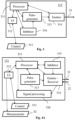
- a remote sensing set 1 compliant with the invention comprises an emission device 11 for emitting pulsed waves 21 towards one or more objects 2 on which measurements are intended to be carried out via a propagation medium 20, and a reception device 12 for receiving waves 22 transmitted by the object(s) 2 upon receiving the waves 21.
- the object 2 illustrated in a generic manner can notably consist in a solid object, airborne molecules or particles, a fluid such as for instance oil, living beings such as for instance schools of fish.
- the medium 20 can in particular consist in the atmosphere or the ocean.
- the waves 21 received by the object 2 generate waves 23 that can be notably reflected, backscattered or emitted by fluorescence.
- the waves 21, 22 and 23 can be of any type, and notably acoustic or electromagnetic - such as radio or light waves. Only a part, generally small, of the waves 23 reaches the reception device 12 as the waves 22.
- the devices 11 and 12 are represented side by side on Figure 1 , but can also be distant from each other. They are thus preferably connected by a remote wired or wireless communication system - for example via a 3G or LTE (for "Long Term Evolution") cell network, a cable transmission associated with local wireless transmissions of the WiFi type, or any other means.
- a remote wired or wireless communication system for example via a 3G or LTE (for "Long Term Evolution”) cell network, a cable transmission associated with local wireless transmissions of the WiFi type, or any other means.
- the emission device 11, noted 111 includes a pulse generator 313 and an emitter 314 receiving pulse signals from the generator 313, for example in electronic form, and emitting the waves 21 in function of those signals. It comprises also one or more processor(s) 311 connected to all the modules of the device 111 requiring control or command operations.
- One or more user interface(s) 312 (Ul), linked notably to the processor 311, allow a user to enter or obtain control or monitoring information 511.
- User interface means here as hereinbelow any appropriate means for entering of retrieving data, information and/or instructions, notably any visual, tactile and/or audio capacities that can encompass notably a screen, a keyboard, a trackball, a touchpad, a touchscreen, a loudspeaker, or a voice recognition system.
- the emission device 111 further comprises a pulse inhibitor 315, which can act on the emitter 314 so as to prevent the transmission of part of the pulse signals, notably according to determined inhibition periods.
- the reception device 12, noted 121 in the first embodiment, comprises as for it a receiver 324 of the waves 22, a spectral filter 325 enabling to select considered frequency ranges, and a signal processing unit 326, dedicated to processing the data from the filter 325.
- the device 121 also includes a processor 321 and a user interface 322, which allows users to manage control or monitoring information 521 and to obtain measurements results 52.
- the devices 111 and 121 are represented as separate entities, they are linked one to the other and can notably be embodied in a same apparatus.
- the processors 311 and 321 can be merged, as well as the user interfaces 312 and 322.
- a common interface can also be utilised in some cases for emitting and receiving waves, such as for example antennas, insofar as that interface is suitable for both types of operations.
- the respective interfaces are distinct.
- bistatic or multistatic radars or sonars are advantageously employed.
- the emission device differs from the preceding one in that it comprises a pulse inhibitor 316 configured for acting upstream of the emitter 314 on the pulse generator 313.
- the emission and reception operations are coupled via signal interference.
- That embodiment is particularly adapted to a lidar using optical heterodyne detection.
- That set 131 comprises like for the emission and reception devices of the first embodiment a processor 331 and a user interface 332, allowing to manage control or monitoring information 531 and to obtain measurement data 52 related to remote sensing. It also comprises the pulse generator 313, the inhibitor 315 (which is acting directly at the emission level in this embodiment) and the signal processing unit 326.
- the specificities of that second embodiment are due to the presence of an emitter-receiver 334 grouping the emission functions of the emitter 314 and the reception functions of receiver 324 and having a coherent detection.
- the waves generated by the emitter 314 on the basis of the pulse signals transmitted by the pulse generator 313 are subject to a partial extraction in addition to the emitted waves 21, by a separator 335.
- the latter communicates the waves to a modulator 336, which transforms the received signal in an appropriate way according to a process known by a person skilled in the art, typically by an offset to a determined frequency.
- the output from the modulator 336 and the signal captured by the receiver 324 are transmitted to an interferometer 337, which in the process indicated above generates a term oscillating around the offset frequency (heterodyne frequency).
- a heterodyne signal, carrying the useful information, can thus be extracted from the interferometer by electronic filtering in the neighbourhood of that frequency.
- the modulator 336 is absent,
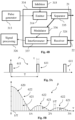
- a periodic rectangular pulse signal takes the form of a repeated gate function P, as visible on Figure 5A , which comprises rectangular units 611, each having a duration ⁇ , and being consecutively spaced one period T apart.
- P a repeated gate function
- the Fourier transform of such a function is given by a function P ⁇ (represented on Figure 5B ), centred on frequency 0 and comprising frequency peaks 621 consecutively spaced one pulse frequency 1/T apart.
- That envelope admits then a main lobe 620 decreasing in frequency down to zero at frequency 1/ ⁇ , followed by globally decreasing lobes 622, each of which covers a frequency range comprised between multiples of 1/ ⁇ and reaching zero at its ends.
- a high ratio of the pulse period T to the pulse duration ⁇ yields a higher number of significant frequency peaks (in the example represented on Figure 5B , that ratio is worth 10).
- the behaviour of the function P ⁇ is similar, in a whole frequency range centered on zero and sufficiently low with respect to 1/ ⁇ , to a sequence of unitary frequency pulses corresponding to instantaneous pulse signals.
- the periodically applied pulses are equated to instantaneous signals instead of gates ( Figure 8A ).
- the corresponding time function D (repeated Dirac distributions) is thus defined by a succession of peaks 630 spaced the pulse period T apart.
- the resulting Fourier transform ( Figure 8B ) is a function D ⁇ comprising an infinite sequence of frequency peaks 640 spaced the pulse frequency 1/T apart.
- the periodic repetition of peaks at the frequency 1/T excites not only the concerned frequency, but also all its multiple frequencies. That phenomena is attenuated more or less quickly in practice in the presence of gate functions, due to the amplitude decrease expressed by the cardinal sine.
- a first example of pulse inhibition illustrated on Figure 9A
- one pulse out of three is removed in the repetition of the peaks 630.
- the result in frequency terms given on Figure 9B , shows that the signal is transformed by the decrease of the peaks 641 located at frequencies multiple of 1/T and by the emergence of new frequency peaks 642.
- the latter are located at frequencies corresponding to a partition into three sections of the frequency ranges bounded by the multiples of the pulse frequency 1/T. More precisely, the peaks 641 reach 2/3 of the amplitude of the peaks of the function D, while the peaks 642 represent 1/3 of that value.
- the introduction of the inhibition pulses therefore leads to an internal spreading between the peaks distributed according to multiples of the pulse frequency 1/T.
- the capability to excite at the same time the pulse frequency and frequencies that are worth the third thereof or their multiples is remarkable as such.
- the loading frequency spectrum relies on the pulse repetition frequency, for example for fast pulses without intra-pulse modulation, it is thereby made possible by a unique wave emission towards an object to access simultaneously information that would normally require more complex implementations or successive measurements over time.
- a gain in measurement speed can then be obtained, regarding notably mobile objects or complex measurements.
- a high pulse repetition frequency is often desirable.
- the pulse inhibition method is then likely to allow in some cases to mitigate the disturbing effects of the pulses without undermining significantly the advantages of fast pulses. Indeed, it amounts to distributing the energy linked to high pulse frequency contents towards lower frequencies, presently down to three times lower in the illustrated example.
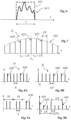
- a pulse inhibition is applied with a single period higher than 3T, of the type KxT with K being an integer greater than 3.
- a frequency spectrum is then obtained, in which the multiples of 1/T are weighted by a factor equal to (K-1)/K with respect to the reference signal D, and the other multiples of 1/(KT) are weighted by a factor 1/K.
- K thus leads to maintaining an all the higher relative weight at the pulse frequency 1/T while involving a larger number of frequencies, but at a relative level of presence in the spectrum that decreases in a sensibly hyperbolic way with K (the ratio of the two levels being worth 1/(K-1)).
- the frequency coverage is thus sensibly refined, by a factor of 35, while making possible a preservation of a high data acquisition pace and a good representation of the pulse frequency in the spectrum.
- the representation of the interspersed frequencies is however relatively weak, the highest relative level corresponding to a factor 1 ⁇ 4 with respect to the peaks associated with the multiples of the pulse frequencies.
- Figures 11A and 11B correspond to periods 3T and 5T, and lead to introducing frequency multiples of 1/(15T) in the spectrum, also according to four distinct levels but closer together than previously:
- the frequency pulse spectrum extends to the elementary frequency equal to the quotient of 1/T by Q 1 ⁇ Q 2 ⁇ Q 3 ⁇ ... ⁇ Q N , and to its multiples.
- the pairwise coprime factors therefore offer a wide range of adjustment possibilities, with effects on the emitted spectrum that are likely to be potentially well managed.
- the simplicity of the frequency level distribution formulas can indeed constitute a precious help in the choice of the parameters.
- the frequency pulse spectrum extends to the elementary frequency equal to the quotient of 1/T by the least common multiple of those factors, and to its multiples.
- the factors associated with the frequency peaks for the pulse inhibitions can be obtained in several manners. One of them consists in obtaining them numerically by Fourier transform.
- Another one consists in applying analytically a Fourier transform to the developments linked to the Dirac distribution sequences, by using the facts that the sum of the roots of unity is worth 0 and that a truncated sequence of Dirac distributions can be replaced with differences between the completed sequence and sequences corresponding to the truncation.
- a possible operation of the remote sensing set 1 comprises the following steps, illustrated on Figure 13 :
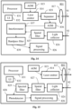
- a coherent detection lidar 801 represented on Figure 14 comprises, in addition to a processor 831 and a user interface 832 (the relations of which with the other elements are not reproduced on the figure), a pulse laser emitter 814, having a variable attenuator.
- the laser can consist for example in a neodymium-based power laser used at 1064 nm, but multiple other implementations remain within the scope of the present disclosure, including notably Rayleigh or Mie lidars, Raman, Fluorescence or Differential absorption lidars. Its average power is for example between 100 and 300 mW, and the emitted pulses have a pulse duration in the order of picoseconds with a pulse repetition frequency comprised between 100 kHz and 1 GHz.
- the obtained laser pulses deliver for example 10 to 50 mJ per pulse.
- Lasers allowing very short high power pulses are also judicious choices for implementing the described processes, including Q-switched or mode-locked lasers.
- the lidar 801 further comprises a separator 835 downstream of the emitter 814 and enabling to separate the emitted beam by reserving a part extracted from that beam to an acousto-optic modulator (AOM) or Bragg cell 836. That modulator 836 is able to apply a predefined frequency offset, allowing to perform an interferometry with received beams.
- Optics 817 are provided for shaping the main laser beam output from the separator 835, before an emission as waves 91.
- the lidar 801 also comprises a second AOM 815, provided for acting on the laser emitter 814 so as to exclude emissions corresponding to the multiples of the repetition frequency T that are predefined for the inhibition.
- Multiple means other than a Bragg cell can be employed for preventing the transmission corresponding to those inhibition periods, including mechanical means such as shutters, chopper wheels or rotating mirrors, or electro-optic or acousto-optic means such as a Pockels cell or a Kerr cell.
- the lidar 801 further comprises a light collector or collecting optics 824 provided for receiving light beams 92 output from the objects to be probed, followed by a spatial filter 827.
- a photodetector serving as an interferometer 837 is provided for collecting the signals output from the filter 827, together with those coming from the modulator 836 and representative of the emitted beams.
- a bandpass filter 839 is adapted to receive the signal output from the interferometer and to extract therefrom a heterodyne signal, communicated to a signal processing unit 826.
- lidar 802 with incoherent detection is represented on Figure 15 .
- it does not include an interferometry system (separator 835, AOM 836, interferometer 837, bandpass filter 839) but a spectral narrow-band filter 825 downstream of the spatial filter 827.
- a photodetector 828 is provided for receiving the obtained signal and transmitting the detection result to the signal processing unit 826.
- FIG. 16 Another application example of the present disclosure concerns a pulse multistatic radar 840, represented on Figure 16 . Further to a processor 841 and a user interface 842 (the relations of which with the other elements are not reproduced on the figure), it includes an emission block 85 and a reception block 86.
- Any frequency ranges can be concerned by the present disclosure, notably comprised between 1 and 100 GHz.
- the emission block 85 comprises a radio emitter 854 fed by a pulse generator 853 via an amplifier 857.
- the pulse generator 853 comprises a permanent oscillator 8531, such as for example a klystron, and a modulator 8532 of the signals emitted by that oscillator 8531.
- the modulator is for example a commutator of the thyratron type, but in some embodiments, its function is fulfilled by the oscillator 8531 itself, consisting in a klystron.
- the pulses produced by the pulse generator 853 have for example a duration in the order of 1 ⁇ s.
- An electronic control unit 856 allows to control the pulses produced by the generator 853, and notably to exclude the pulse inhibition periods.
- the emission block 85 also comprises a waveguide 858 provided for receiving the pulse signal output from the emitter 854 and for transmitting it to an antenna 859 for emitting waves 95 towards the objects to be probed.
- the reception block 86 includes an antenna 869 for receiving waves 96 from the objects to be probed, together with a radio receiver 864.
- the output of that receiver 864 is submitted to a filter 865 before being transmitted to a signal processing unit 866.
- FIG. 17 An additional implementation represented on Figure 17 regards a bistatic active sonar 870.
- the latter includes, further to a processor 871 and a user interface 872 (the relations of which with the other elements are not reproduced on the figure), an emission block 88 and a reception block 89.
- the sonar 870 enables emissions at frequencies comprised between 10 and 100 kHz.
- the emission block 88 comprises a sonar projector 880, adapted to generate pulse signals intended for an antenna 889 made up of hydrophones, for transmitting acoustic waves 98.
- the sonar projector 880 includes a signal generator 883 under the control of an electronic control unit 886. The latter is able to act on the projector 880 so as to prevent the transmission of pulse signals corresponding to the inhibition periods.
- the projector 880 also comprises successively, downstream from the signal generator 883, an amplifier 887, an electroacoustic transducer 888, for example piezoelectric or magnetostriction-based, and a beam generator 884. The latter is able to transmit the emission signals to the hydrophones 889.
- the reception block 89 includes hydrophones 899 able to receive the acoustic waves 99 received as echoes from objects to be probed, an analog-to-digital converter 894 required for exploiting the signals and a signal processing unit 896.
Description
- The present invention relates to a device and a process for remote sensing by means of pulse signals, in emission and/or in reception. It concerns generally the technologies using waves sent towards objects to be probed, and is more particularly related to the fields of lidars, radars and sonars.
- Remote sensing techniques, consisting in acquiring information on distant objects by means of measuring instruments having no contacts with those objects, are exploited in wide application ranges. They amount to sending waves towards those objects, retrieving waves transmitted in response to such loads, and analysing the received waves.
- The term "transmission" as employed in the present disclosure covers any kind of wave propagation from a wave loaded object, and can refer notably to reflection, scattering, diffusion or fluorescence.
- Thus, the radars (initially an acronym for RAdio Detection And Ranging) use radio waves reflected by a target. The lidars (initially an acronym for Light Detection And Ranging) enable to conduct remote measurements based on the analysis of properties of a light beam transmitted back to its emitter, most often from a laser emission. The beams transmitted by the target can be reflected, backscattered in an elastic way (Rayleigh and Mie diffusions) or an inelastic way (Raman diffusion) or result from fluorescence. The sonars (initially an acronym for SOund Navigation And Ranging) rely on the sound propagation in water for detecting and studying submarine objects, and the active sonars provide for emitting sound pulses and listening to echoes.
- Though those technologies are quite disparate, notably due to the concerned frequency ranges, wave types and target applications, their main principles are rooted in analogous aspects.
- One of their points of commonality consists in the possible or systematic exploitation of periodically pulsed waves, sent towards the target objects. Each of those pulses is commonly subject to the modulation of a carrier frequency sensibly higher than the pulse repetition frequency. Typically, pulse compression relies on modulating each emitted pulse and on correlating a corresponding received signal with the emitted pulse, so as to increase range resolution.
- The spectral effects linked notably to the pulse periodicity and duration are then often considered as parasitic, and various protocols and methods aim at eliminating or mitigating their effects. The pulse repetition is then mainly intended to average results out, or to follow up evolutions over time.
- However, in various situations, those working modes prove insufficient to obtain appropriate information, notably in presence of mobile, complex or diffuse objects, or when information must be obtained on inherent properties of objects - and not only e.g. on a position or a speed. One of the major reasons for those limitations is the use of one or several predefined modulation frequencies, which can prove improper or too restrictive for meeting such pursued objectives.
- Typically, in the radar field, a pulse is usually emitted and reflected before a next pulse is emitted. This involves the existence of a distance range ambiguity and leads to defining a maximum range inversely proportional to the pulse repetition frequency (PRF). Increasing the inter-pulse quiet period, and thereby decreasing the PRF, thus provides a longer-range signal. By contrast, increasing the PRF enables easier detection due to higher emitted radio energy, but within a shorter maximum range.
- The obtained information is generally focused on the distance and possibly velocity and/or surface configuration of detected objects.
- Multiple methods have been proposed for extending the related unambiguous radar range beyond its conventional value. Some of them rely on not emitting selected pulses of a uniform pulse train.
- In particular, the article "Inter-Pulse Coding and Coherent-on-Receive Modifications of Magnetron-Based Marine Radar - Experimental Results" to E. Ben-Yaacov et al., IEEE, Nov. 7, 2011, pages 1-9, XP032120996, describes the exploitation of a magnetron-based non-coherent radar, in which a periodical coding of a Pulse Repetition Interval (PRI) is applied. In this respect, some of the pulses are omitted according to a binary sequence based on a Manchester coding, such a binary sequence being cross-correlated with a stored reference sequence.
- Utilizing an incomplete pulse train has also been proposed in patent application
EP-1431774 A1 (in the name of Thales ) for pulse Doppler measurements, notably for a pulse-Doppler radar. Such a pulse train has a PRI sequence of modulated pulses in which some predefined pulses are not emitted, according to a regular pattern of pulses and gaps. This enables to release emission-reception schedules that can be exploited through pulse train interlacing, for example with a view to different look direction measurements. - Those documents rely on disconnecting the effects of successive pulses on the object to be probed. Indeed, the proximity of such successive pulses appears to be a source of undesirable interactions, of schedule unavailability or of supplementary power expense. Accordingly, the PRF is not intended to produce any specific spectral loading effect on the target object, but merely to provide return data at an appropriate pace.
- Among the technologies developed for remedying the existing limits and constraints, systems for emitting very short pulses have been developed. Such pulses allow to cover a broad range of load frequencies and are thus potentially carrying a significantly higher amount of information.
- In particular, as regards lasers, Q-switching allows the generation of output pulse beams having a high power, which can reach the gigawatt level. Mode-locking is another laser technique enabling to produce short and intensive light pulses, and is exploited in providing femtosecond lasers. Those techniques are however relatively complex and costly, and their applications remain focused today on specific situations.
- Furthermore, it is known to exploit pulse repetition frequencies in some measurement techniques, notably for very high frequencies compared with the frequency ranges commonly used in the related fields. Such implementations, when possible, are however most often considered rather in terms of circumstantial commodities than for bringing added value regarding the analysis of remote objects.
- In order to cover efficiently a broad range of load frequencies, it was proposed in patent document
US-2009/0051926 A1 (in the name of NASA) to use a pulsed laser including a plurality of sources coupled to a modulator and respectively tuned to distinct and separated frequency ranges. The generated pulses are collectively amplified in a same amplifier. This achievement enables to extend significantly and simultaneously the excited frequency field, but at the expense of a complexity that is restricting it to specific applications fields. - Moreover, several methods exist for enabling short laser pulses (in the order of picoseconds) at high repetition rates, without penalizing the results. This includes autocorrelators or ultrafast photodiodes. In the patent document
WO-2015/001432 A1 (inventor C. Braggio ), a method is described for allowing to identify precisely the features of short and ultrashort pulses (down to tens of femtoseconds) having high repetition frequencies (up to tens of GHz), by means of radio waves generated by a crystal impacted by a pulse train. That information enables to neutralize measurement disturbances caused by the pulse nature of the emitted waves. - It was also observed in patent document
US 2014/0231679 A1 (inventors K. Kremeyer et al. ) that the effects generated by the interaction of laser pulses with a medium can be controlled by tuning the pulse parameters, such as notably the pulse durations and repetition frequencies. - The present invention aims in particular at providing additional remote sensing tools enabling to modify the spectral properties of pulsed waves. More precisely, a purpose thereof is to offer complementary possibilities for simultaneous multifrequency loading in the form of pulse signals allowing, in appropriate implementations, to complete and refine the measurement outputs in a flexible way.
- In preferred embodiments, the invention aims at providing such tools for pulsed waves having a high repetition frequency and a short pulse duration.
- Another objective of the invention is to allow, in some execution modes, a refinement of the emission spectrum in the neighbourhood of one or more modulation frequencies.
- The invention is also aimed at enabling, in relevant cases, to obtain computation parameters helpful in interpreting the results precisely and efficiently, and to proceed quite swiftly and simply with changes in measurement adjustment variables.
- The invention is broadly applicable to remote sensing methods possibly implementing pulsed waves, and can cover notably lidar, radar, sonar and ultrasound monitoring.
- In this respect, an object of the invention is an emission device for remote sensing according to
claim 1. - The pulse generator(s), wave emitter(s) and processor(s) are such that the pulse period contributes to the at least part of the frequency content on which producing the measurement information is based.
- According to the invention, the emission device comprises at least one pulse inhibition system configured for preventing periodically the emission of the waves by the emission device, according to at least one inhibition period proportional to the pulse period and equal to at least three times that pulse period. The pulse generator(s), wave emitter(s) and processor(s) are such that the inhibition period(s) also contribute(s) to the at least part of the frequency content on which producing the measurement information is based.
- A measurement object designates any kind of surveyed matter, whether in a solid, gas, liquid or plasma state, or others. The object may thus have possibly a changing shape or an evolving constitution.
- A pulse signal consists in a single and abrupt signal variation, which may possibly include itself regular or modulated oscillations, or a plurality of internal shorter pulses.
- Producing measurement information "based on" part of a frequency content means that the concerned part of the spectral composition of the waves coming from the measurement object is intended to be exploited in the monitoring and analysis of received samples.
- The pulse period "contributes" to the relevant part of the frequency content of the transmitted waves, in the sense that the associated spectrum is incorporating effects of the pulse period on interactions between the emitted waves and the measurement object, and that those effects are exploited in extracting the measurement information out of the waves received from the object.
- A similar observation applies to the inhibition period. It can be observed that the disclosed emission device can enable accordingly to decrease in a controlled, flexible and possibly dynamic way a fundamental frequency of the emitted pulses and/or a fundamental offset frequency with respect to wave frequencies of the emitted pulses.
- The contributions of the pulse and inhibition periods to the frequency content of the monitored transmitted waves may in particular translate into corresponding periodicities preserved from the emitted waves to the monitored waves. However, cases where such periodicities are modified are also covered, which may happen notably when the measurement objects are moving, due to the Doppler effect, or through inelastic scattering or photoluminescence in the interactions between the emitted waves and the measurement objects. The present disclosure also pertains to situations in which the repeated pulses in the emitted waves are not systematically turned to repeated pulses in the transmitted waves, but have more complex effects, due for example to fluorescence mechanisms at the measurement objects.
- As well known to a person skilled in the art, the number of considered successive pulse periods and inhibition periods must be sufficient for their effective contributions to the frequency content on which producing the measurement information is based. Since the inhibition period is larger than the pulse period, that inhibition period dictates a representative time range.
- Also, where more than one different inhibition periods are exploited (none of them being a multiple of any other), the representative time range must take the greatest of them into account. As will be clearer to the reader below, the representative time range is in fact preferably encompassing a sufficient number of the least common multiple of the different inhibition periods. In variant embodiments, however, multiples of the different inhibition periods above a threshold lower than, or a small number of times larger than, the least common multiple are disregarded in determining the time range, insofar as their contributions are deemed negligible.
- A "sufficient number" of successive periods is advantageously greater than 100, preferably greater than 1000 and still preferably greater than 10,000. That number depends on various criteria, including without limitation the wave frequencies, the wave coherence or incoherence, the value of the pulse period, the use or not of modulation and if any, the modulation specificities, the exploitation of interferometry or not, the duty factor of the period pulses (ratio of the pulse duration to the pulse period), the type of remote sensing, the measurement object characteristics and complexity, the investigated information, and the measurement accuracy.
- Several features of the emission device are directed to what happens downstream, at the levels of the measurement object and of the receiver. This regards the frequency content of the waves transmitted by the object and the determination of the measurement information from the monitoring of those waves. Those downstream functional aspects are in fact closely reflected in the constitution and/or settings of the emission device.
- In particular, the emitted waves must be able to interact with the measurement object in such a way that the resulting waves transmitted by the object are carrying spectral information causally associated with the pulse and inhibition periods, which is adapted to be exploited for deriving the measurement information.
- In this respect, the emission device is either taking care itself of the processing of the waves received from the object (which may be possibly performed through interferences between signals corresponding respectively to the emitted waves and to those received waves), or communicating relevant processing parameters to an appropriate reception set.
- In the latter case, the relevant parameters communicated to the reception set are notably driven by having effects of the pulse and inhibition periods integrated and considered in the frequency spectrum of the transmitted waves for the monitoring and signal processing modes.
- The set of parameters may notably include various items of information on a coded pulse sequence having a periodic pulse inhibition and/or on spectral processing data pertaining to a time sequence extending over multiple pulse waves.
- As a matter of fact, the present disclosure belongs to the class of technologies in which the pulse repetition is made an integral part of the spectral loading which is exploited for gaining relevant information from interactions with probed objects.
- Consequently, it contrasts in particular with conventional radar systems, in which the pulse signals correspond to dissociated interaction steps and for which what matters is the coupling of the sent waves with the probed objects within each pulse. The cross-processing of data between successive pulses, as carried out in some radar technologies, remains in line with that observation. This includes notably pulse-Doppler radars exploiting phase offsets over successive pulses for deriving velocity information, and radars with coded pulse sequences cross-correlated with reference sequences.
- It can further be observed that pulse omissions in known PRI radar solutions, as implemented in the above-cited IEEE reference to Ben-Yaacov or
EP-1431774 A1 patent application, is carefully deprived of any inhibition periodicity within a given pulse train. Even a partial periodicity would indeed have undesired effects, either by preventing efficient extension of the unambiguous range beyond the conventional limit (IEEE reference) or by entailing costly sequence redundancies in the processing of a covariance matrix built from signal samples (EP-1431774 A1 ). - In the class of technologies making use of the pulse periodicity for spectrally exciting a surveyed object, periodically omitting pulses is quite unexpected and contrasts strongly with usual practice.
- Should a skilled person have considered the state of art in neighbouring fields so as to enhance data collecting, regularly omitting some of the pulses could have been envisaged as a way to facilitate signal processing or to enrich the information range. However, the skilled person would have established no connection between the frequency content of the transmitted waves exploited in producing measurement information, and an inhibition period.
- Surprisingly, the pulse repetition periodicity is thus disturbed and made intermittent, while being able to remain potentially rich in information and in regulated interactions. That mode of controlled pulse modification offers a broad range of possibilities, for an emission frequency spectrum dominated by the repetition frequency as well as for a spectrum dictated essentially by fast intra-pulse modulations or coherent waves.
- The invention further applies to macro-pulses made up of numerous micro-pulses.
- The emission device makes possible, in some implementations, a use of conventionally exploited equipment, without requiring sophisticated additional means. It can thus, in advantageous embodiments, be particularly economical and convenient to use.
- In addition, that device can potentially allow very flexible changes of the inhibition period(s), including in various configurations, thus enabling fast successive adjustments and/or cross-referencing and combinations of measurement information.
- The operation of the emission device has notably the effect of refining the frequency spectrum with respect to the pulse period, with a ratio equal to the least common multiple of the factors associated with the inhibition periods. That effect is however weighted in function of the frequency configuration of the emitted waves. The operation has the concomitant effect of partially spreading the frequency spectrum between peaks related to the pulse frequency.
- In some embodiments, the pulse generator and the wave emitter are not dissociated - in particular in a laser.
- The waves can be of various types depending on the embodiments. In particular, they can consist in acoustic, radio, ultrasound, or electromagnetic waves in the infrared, visible, ultraviolet or X-ray fields. Further, the wave transmission by the object can take place in any manner, such as notably by reflection, elastic or inelastic scattering (including in particular backscattering) or fluorescence.
- The remote sensing can regard, among other fields, meteorology, air traffic control, astronautics, topography, geoscience and environment, vehicle remote control, autonomous car management, robotics, submarine detection, surface light characterization (hence notably Virtual Reality), object recognition, Internet of Things and biomedical engineering.
- The invention is particularly attractive for swiftly refining complex data collecting on a surveyed object. In advantageous implementations, it can be especially relevant for finely characterizing surface properties of solid objects and volume properties of non-solid objects such as in particular gases, notably when those properties are wavelength-dependent. The probed properties may include notably geometric, structure and composition data.
- Preferably, the inhibition system is configured so that the inhibition periods include at least two distinct inhibition periods, none of them being a multiple of any other. In advantageous embodiments, the inhibition system is then configured so that the distinct inhibition periods have ratios with respect to the pulse period which are pairwise coprime.
- The exploitation of several ratios between the inhibition periods and the pulse period extends significantly the potentialities for tuning and refining the frequency spectrum. More precisely, it allows a controlled decrease of the fundamental repetition frequency of the emitted pulses, like with a unique inhibition period, but while at the same time assigning higher weights to dedicated harmonics (multiples of the fundamental frequency). Such implementations thereby leverage significantly the potential probing refinement capacity of the system.
- Furthermore, pairwise coprime ratios offer notably the advantage of being able to provide simple analytical formulations, likely to facilitate precise computations and finer result interpretations.
- The number of inhibition periods can be quite variable and depends on the kinds of intended applications. A small number, comprised between one and three, appears to provide generally outputs more readily accessible to measurements. Nevertheless, a higher number proves interesting for exploring frequencies with finer frequency steps.
- In a first series of embodiments, the waves emitted by the emission device are unmodulated over each of the pulse signals.
- In particular related implementations, those emitted waves having a frequency spectrum and the elementary time windows having a pulse duration, the emission device is configured so that the frequency spectrum is determined essentially by the pulse period and the pulse duration.
- According to those embodiments, the pulses are decisive for the spectrum constitution, no carrier frequency and no frequency modulation playing a significant role within each pulse. More precisely, the pulse duration and the pulse repetition frequency (taking into account the modifications induced by the inhibition periods) determine then the frequency spectrum with a precision higher than 95 %, and advantageously with an accuracy of 1 % or less. In some embodiments, those pulses are micro-pulses making up groups of macro-pulses.
- That precision is assessed in the following natural way. A theoretical reference rectangular pulse train is determined, comprising rectangular pulses having a same pulse duration and a same pulse period as the emitted waves. Each of those rectangular pulses has an amplitude that is associated with an energy corresponding to an averaged pulse energy in the effectively emitted waves. A difference between the effective pulse train and the theoretical reference rectangular pulse train results in a deviation pulse train.
- A ratio between the energy contained in the deviation pulse train and the energy contained in the theoretical rectangular pulse train is then representative of the degree of accuracy in representing the effective pulse train by the theoretical rectangular pulse train. Namely, a pure (unrealistic) rectangular wave signal would correspond to a bias of 0 %. The mentions above according to which the precision is higher than 95 %, and advantageously with an accuracy of 1 % or less, therefore mean that the energy ratio is respectively lower than 5 % and lower than or equal to 1 %.
- Such configurations are possible notably in case of very short pulses (with respect to an operated range of shorter carrier wavelengths) together with incoherent waves over the pulse durations.
- The inhibition period(s) is/are then able to provide precious information at intermediary frequencies between the frequencies that are multiples of the pulse frequency. It is thus made notably possible to refine the results obtained initially on the basis of regular periodic pulses, and then to iteratively complete the information. The user may also select a priori the most judicious corresponding parameters, thereby the relevant ratios for the inhibition periods. Another potential advantage is the simultaneous retrieval of various measurement information data, related to a plurality of intermediary frequencies located between the pulse frequency peaks.
- In alternative implementations, the emission device is configured so that the unmodulated waves emitted by the emission device have a carrier frequency over the pulse durations that plays a determining role in the spectral composition of those waves, the waves being coherent on each pulse.
- The pulse signals modulating the carrier waves in a coded way by means of the inhibition periods are then advantageously providing complementary spectral loading, which corresponds to offset frequencies with respect to the carrier frequency. Those offset frequencies are further distributed schematically around the carrier frequency, with frequency steps and associated amplitude weights given by the pulse and inhibition periods.
- In a second series of embodiments, the elementary time windows having a pulse duration, the emission device is configured so that the waves emitted by the emission device comprise at least one modulation at a frequency higher than the reciprocal of the pulse duration.
- This regards a classic case of pulsed waves, used notably with lidars (the modulation carrier frequencies being typically in the order of THz, the pulses being in the order of ns and the repetition frequencies in the order of GHz). The introduction of the inhibition periods has then the effect of weighting the evolution variables of the frequency signals around the modulation frequency or frequencies, and is likely to induce a spectral distribution of the signal that is more progressive than with convolutions associated exclusively with the pulse period and duration.
- Those embodiments can, in some appropriate modes, prove useful notably for exploring more finely the reaction of objects to frequencies neighbouring the modulation frequency or the carrier frequency. They also offer potentially interesting and flexible parameters for acting notably against disturbances caused by short and ultrashort pulses in high-frequency measurements.
- Several types of modulation are covered by the present disclosure, including in particular amplitude modulation, frequency modulation and phase modulation.
- The two series of embodiments above are not exhaustive, the pulses carrying possibly for example a complex spectral content (such as e.g. chirping).
- In a particular implementation of the inhibition system(s), the latter is adapted to cooperate with the pulse generator so that the pulse signals are truncated according to the inhibition period(s).
- It is thus proceeded upstream, before going through the wave emitter. When feasible, that embodiment can be advantageous in that it is possible to act in several situations with known electronic means while having energy efficient operations.
- In another implementation of the inhibition system(s), the latter is adapted to cooperate with the wave emitter so that the wave emission by the emitter is inactivated for the waves corresponding to the inhibition period(s).
- It is thereby acted downstream, advantageously after the pulse generator has produced regular periodic signals at the pulse period and has communicated them to the wave emitter. A periodic transmission blocking can be operated in different ways depending on the concerned technologies, for example in optics by a system having controlled shutter(s) or mirrors.
- Another object of the invention is a reception set for remote sensing according to claim 9.
- According to the invention, the system for frequency consideration is configured to take into account at least one inhibition period proportional to the pulse period and equal to at least three times that pulse period, so that the inhibition period(s) also contribute(s) to the at least part of the frequency content on which producing the measurement information is based.
- The reception set is thus appropriate to the exploitation of inhibition periods as described above.
- Preferably, that reception set is adapted to waves transmitted by the object(s) from waves emitted by an emission device compliant with any of the embodiments disclosed above.
- Preferably also, the reception set is configured to be coupled with such an emission device. In some embodiments, that coupling is a wired connection or the inclusion in a same apparatus. In other embodiments, it is achieved by remote communication making possible the exchange of relevant data.
- Advantageously, the system for frequency consideration is configured so that the inhibition periods include at least two distinct inhibition periods, none of those distinct inhibition periods being a multiple of any other.
- In a particular implementation, the system for frequency consideration is adapted to take into consideration a main frequency step corresponding to the pulse period of the emitted waves and at least one secondary frequency step corresponding to the inhibition period(s) and constituting at least one divisor or the main frequency step.
- That consideration of the main and secondary frequency steps for generating the measurement information can be based notably on spectral filtering, interferometry with homodyne or heterodyne detection, or analog-to-digital conversion.
- In advantageous embodiments, the main frequency step is worth the pulse repetition frequency (i.e. the reciprocal of the pulse period), while the at least one secondary frequency step is worth an associated at least one pulse inhibition frequency (i.e. the reciprocal of an associated at least one inhibition period). The ratios between the inhibition periods and the pulse period are then the same as the ratios between the main frequency step and the secondary frequency steps.
- In other advantageous embodiments adapted to taking Doppler shifts into account, the main frequency step is equal to the product of the pulse repetition frequency by a factor given by speed characteristics of the measurement object, while the at least one secondary frequency step is equal to the product of the at least one pulse inhibition frequency by the same factor.
- The invention also concerns a remote sensing set according to
claim 12. - Interferometry, adapted to the target frequency or frequencies by means of notably an appropriate modulation on the basis of the emission carrier frequency, can in some advantageous situations allow a high efficiency and measurement accuracy. In addition, the signals at the pulse frequency are likely to enable in multiple cases to obtain in a relatively straightforward and simple way the secondary frequencies excited under the effect of the periodic pulse inhibitions.
- Another object of the invention is a remote sensing apparatus according to claim 13 comprising an emission device and/or a reception set and/or a remote sensing set compliant with the present disclosure, that apparatus being a lidar, a radar, an active sonar or an ultrasound instrument.
- The invention further concerns an emission process for remote sensing, according to claim 14.
- The pulse period contributes to the at least part of the frequency content on which producing the measurement information is based.
- According to the invention, the process includes preventing periodically the emission of those waves, according to at least one inhibition period proportional to the pulse period and equal to at least three times that pulse period, the inhibition period(s) also contributing to the at least part of the frequency content on which producing the measurement information is based.
- That emission process is preferably executed by an emission device compliant with the present disclosure, in any of its embodiments.
- The invention further concerns a reception process for remote sensing according to
claim 15. - According to the invention, the process includes taking into consideration at least one inhibition period proportional to the pulse period and equal to at least three times that pulse period, so that the inhibition period(s) also contribute(s) to the at least part of the frequency content on which producing the measurement information is based.
- The invention also pertains to a computer program adapted to perform steps of the above emission process for remote sensing and/or reception process for remote sensing.
- It also regards a non-transitory program storage device, readable by a computer, tangibly embodying a program of instructions executable by the computer to perform a process compliant with the disclosure.
- Such a non-transitory program storage device can consist, without limitation, in an electronic, magnetic, optical, electromagnetic, infrared, or semiconductor device, or in any suitable combination of the foregoing. As a purely illustrative and not exhaustive purpose, it can be a portable computer diskette, a hard disk, a ROM (Read-Only Memory), an EPROM (Erasable Programmable ROM) or a Flash memory, or a portable CD-ROM (Compact-Disc ROM).
- The invention also pertains to a signal according to claim 17.
- The invention will be better understood, and other specific features and advantages will emerge more clearly in the light of the following description of example embodiments, provided in a non-restrictive way with reference to the annexed drawings wherein:
-
figure 1 is a schematic drawing representing the working of a remote sensing set compliant with the invention; -
figure 2 represents as a block diagram a first embodiment of the sensing set offigure 1 , involving distinct and communicating entities for the respective emission and reception parts; -
figure 3 represents as a block diagram a variant of the first embodiment offigure 2 ; -
figure 4A illustrates as a block diagram a second embodiment of the sensing set offigure 1 , involving a coupling by interferometry between the emission and reception parts; -
figure 4B details the emitter-receiver block offigure 4A ; -
figure 5A shows time periodic pulses in the form of gate signals; -
figure 5B represents the Fourier transform of the signal offigure 5A , for a pulse repetition period equal to 10 times the pulse duration; -
figure 6 represents a pulse time window in the case of a signal oscillating during the pulse duration; -
figure 7 shows the frequency distribution of a signal modulated at a frequency ν0 during periodic pulse windows of period T; -
figure 8A represents for sake of disclosure convenience a time periodic signal comprising instantaneous pulses (repeated Dirac); -
figure 8B gives the frequency transformation of the signal offigure 8A ; -
figure 9A shows the introduction of an inhibition period equal to 3 times the pulse period in the theoretical diagram offigure 8A ; -
figure 9B gives the frequency transformation of the signal offigure 9A ; -
figure 10A shows the introduction of two inhibition periods equal respectively to 5 and 7 times the pulse period in the theoretical diagram offigure 8A ; -
figure 10B gives the theoretical frequency transformation of the signal offigure 10A ; -
figure 11A shows the introduction of two inhibition periods equal respectively to 3 and 5 times the pulse period in the theoretical diagram offigure 8A ; -
figure 11B gives the frequency transformation of the signal offigure 11A ; -
figure 12A shows the introduction of two inhibition periods equal respectively to 4 and 6 times the pulse period in the theoretical diagram offigure 8A ; -
figure 12B gives the frequency transformation of the signal offigure 12A ; -
figure 13 presents a flow chart of performing the remote sensing with the remote sensing set offigure 1 ; -
figure 14 is a block diagram illustrating a lidar integrating the functionalities of a remote sensing set compliant withfigure 1 , in a first embodiment using interferometry; -
figure 15 is a block diagram illustrating a lidar integrating the functionalities of a remote sensing set compliant withfigure 1 , in a second embodiment using spectral filtering at the receiver level; -
figure 16 is a block diagram illustrating an implementation of a radar integrating the functionalities of a remote sensing set compliant withfigure 1 ; -
figure 17 is a block diagram illustrating an implementation of a sonar integrating the functionalities of a remote sensing set compliant withfigure 1 . - The present description illustrates the principles of the present disclosure. It will thus be appreciated that those skilled in the art will be able to devise various arrangements that, although not explicitly described or shown herein, embody the principles of the disclosure and are included within its spirit and scope.
- All examples and conditional language recited herein are intended for educational purposes to aid the reader in understanding the principles of the disclosure and the concepts contributed by the inventor to furthering the art, and are to be construed as being without limitation to such specifically recited examples and conditions.
- Moreover, all statements herein reciting principles, aspects, and embodiments of the disclosure, as well as specific examples thereof, are intended to encompass both structural and functional equivalents thereof. Additionally, it is intended that such equivalents include both currently known equivalents as well as equivalents developed in the future, i.e., any elements developed that perform the same function, regardless of structure.
- Thus, for example, it will be appreciated by those skilled in the art that the block diagrams presented herein represent conceptual views of illustrative circuitry embodying the principles of the disclosure. Similarly, it will be appreciated that any flow charts, flow diagrams, and the like represent various processes which may be substantially represented in computer readable media and so executed by a computer or processor, whether or not such computer or processor is explicitly shown.
- The functions of the various elements shown in the figures may be provided through the use of dedicated hardware as well as hardware capable of executing software in association with appropriate software. When provided by a processor, the functions may be provided by a single dedicated processor, a single shared processor, or a plurality of individual processors, some of which may be shared. Moreover, explicit use of the term "processor" should not be construed to refer exclusively to hardware capable of executing software, and refers in a general way to a processing device, which can for example include a computer, a microprocessor, an integrated circuit, or a programmable logic device (PLD). Additionally, the instructions and/or data enabling to perform associated and/or resulting functionalities may be stored on any processor-readable medium such as, e.g., an integrated circuit, a hard disk, a CD (Compact Disc), an optical disc such as a DVD (Digital Versatile Disc), a RAM (Random-Access Memory) or a ROM memory. Instructions may be notably stored in hardware, software, firmware or in any combination thereof.
- It should be understood that the elements shown in the figures may be implemented in various forms of hardware, software or combinations thereof. Preferably, these elements are implemented in a combination of hardware and software on one or more appropriately programmed general-purpose devices, which may include a processor, memory and input/output interfaces.
- A remote sensing set 1 compliant with the invention, as represented on
Figure 1 , comprises anemission device 11 for emittingpulsed waves 21 towards one ormore objects 2 on which measurements are intended to be carried out via apropagation medium 20, and areception device 12 for receivingwaves 22 transmitted by the object(s) 2 upon receiving thewaves 21. - According to the implementations, the
object 2 illustrated in a generic manner can notably consist in a solid object, airborne molecules or particles, a fluid such as for instance oil, living beings such as for instance schools of fish. The medium 20 can in particular consist in the atmosphere or the ocean. Thewaves 21 received by theobject 2 generatewaves 23 that can be notably reflected, backscattered or emitted by fluorescence. Thewaves waves 23 reaches thereception device 12 as thewaves 22. - The
devices Figure 1 , but can also be distant from each other. They are thus preferably connected by a remote wired or wireless communication system - for example via a 3G or LTE (for "Long Term Evolution") cell network, a cable transmission associated with local wireless transmissions of the WiFi type, or any other means. - In a first embodiment (
Figure 2 ), theemission device 11, noted 111, includes apulse generator 313 and anemitter 314 receiving pulse signals from thegenerator 313, for example in electronic form, and emitting thewaves 21 in function of those signals. It comprises also one or more processor(s) 311 connected to all the modules of thedevice 111 requiring control or command operations. - One or more user interface(s) 312 (Ul), linked notably to the
processor 311, allow a user to enter or obtain control ormonitoring information 511. - User interface means here as hereinbelow any appropriate means for entering of retrieving data, information and/or instructions, notably any visual, tactile and/or audio capacities that can encompass notably a screen, a keyboard, a trackball, a touchpad, a touchscreen, a loudspeaker, or a voice recognition system.
- The
emission device 111 further comprises apulse inhibitor 315, which can act on theemitter 314 so as to prevent the transmission of part of the pulse signals, notably according to determined inhibition periods. - The
reception device 12, noted 121 in the first embodiment, comprises as for it areceiver 324 of thewaves 22, aspectral filter 325 enabling to select considered frequency ranges, and asignal processing unit 326, dedicated to processing the data from thefilter 325. Like for theemission device 111, thedevice 121 also includes aprocessor 321 and auser interface 322, which allows users to manage control ormonitoring information 521 and to obtain measurements results 52. - Though the
devices processors user interfaces - In a variant embodiment of the
emission device 11, noted 112 and represented onFigure 3 , the emission device differs from the preceding one in that it comprises apulse inhibitor 316 configured for acting upstream of theemitter 314 on thepulse generator 313. - In a second embodiment of the remote sensing set, illustrated on
Figure 4A and noted 131, the emission and reception operations are coupled via signal interference. That embodiment is particularly adapted to a lidar using optical heterodyne detection. That set 131 comprises like for the emission and reception devices of the first embodiment aprocessor 331 and auser interface 332, allowing to manage control ormonitoring information 531 and to obtainmeasurement data 52 related to remote sensing. It also comprises thepulse generator 313, the inhibitor 315 (which is acting directly at the emission level in this embodiment) and thesignal processing unit 326. - The specificities of that second embodiment are due to the presence of an emitter-
receiver 334 grouping the emission functions of theemitter 314 and the reception functions ofreceiver 324 and having a coherent detection. As visible onFigure 4B , the waves generated by theemitter 314 on the basis of the pulse signals transmitted by thepulse generator 313 are subject to a partial extraction in addition to the emitted waves 21, by aseparator 335. The latter communicates the waves to amodulator 336, which transforms the received signal in an appropriate way according to a process known by a person skilled in the art, typically by an offset to a determined frequency. - The output from the
modulator 336 and the signal captured by thereceiver 324 are transmitted to aninterferometer 337, which in the process indicated above generates a term oscillating around the offset frequency (heterodyne frequency). A heterodyne signal, carrying the useful information, can thus be extracted from the interferometer by electronic filtering in the neighbourhood of that frequency. - In an alternative embodiment, particularly adapted to a lidar using optical homodyne detection, the
modulator 336 is absent,
The following part of the disclosure will help to gain more insight into the stakes and consequences of the pulse inhibition. - The frequency properties of a periodic rectangular pulse signal are well known, and very useful for examining the effective properties of periodic pulse signals. Such a time signal takes the form of a repeated gate function P, as visible on
Figure 5A , which comprisesrectangular units 611, each having a duration τ, and being consecutively spaced one period T apart. According to formulas known from the state of the art, the Fourier transform of such a function is given by a function P̂ (represented onFigure 5B ), centred onfrequency 0 and comprising frequency peaks 621 consecutively spaced onepulse frequency 1/T apart. Those peaks follow a cardinal sine (noted sinc)envelope 622, the expression of which is given below in function of frequency v, the notation δ designating the Dirac distribution schematically associated with punctual peak values:

- That envelope admits then a
main lobe 620 decreasing in frequency down to zero atfrequency 1/τ, followed by globally decreasinglobes 622, each of which covers a frequency range comprised between multiples of 1/τ and reaching zero at its ends. Thus, a high ratio of the pulse period T to the pulse duration τ yields a higher number of significant frequency peaks (in the example represented onFigure 5B , that ratio is worth 10). - When this ratio reaches a sufficient level, for example 100, the behaviour of the function P̂ is similar, in a whole frequency range centered on zero and sufficiently low with respect to 1/τ, to a sequence of unitary frequency pulses corresponding to instantaneous pulse signals.
- Knowing the mechanisms of that repeated gate function P is important (see
Figure 6 ), because the periodic pulses of any kind can be expressed in a general way as the product over time of therectangular units 611 of the function P with adetermined signal 613 during a pulse duration τ. The frequency behaviour of that time product is then obtained by convolution of the Fourier transforms of the two functions. - In particular, it is interesting to note the frequency spectrum obtained for a frequency modulation at a frequency ν0, periodically repeated in the
rectangular units 611. For sake of convenience, the presentation is made on the ground of a coherent signal at frequency ν0 (seeFigure 7 ), while modulations can yield various kinds of spectral modifications depending notably on the type of performed modulations. Such a function G has a frequency spectrum Ĝ centred on the frequency ν0, and evolving in its neighbourhood analogously to the transform P̂ of the gate function in the neighbourhood of zero. Hence it comprises frequency peaks 625 spaced the pulse frequency apart and arranged according to anenvelope 624 given by a cardinal sine that tends towards zero when the frequency tends towardsv 0 + 1/τ. - Consequently, when the modulation frequency ν0 (or the carrier frequency) is very high with respect to 1/τ, which is for example commonly the case for pulsed lasers, the frequency range excited around ν0 is relatively narrow. The increased capacities in very short durations and high repetition frequencies and the associated advantages lead however increasingly often to situations in which the frequency loads in the neighbourhood of ν0 take on greater importance.
- In an extreme case, anyway convenient for understanding better the involved mechanisms, the periodically applied pulses are equated to instantaneous signals instead of gates (
Figure 8A ). The corresponding time function D (repeated Dirac distributions) is thus defined by a succession ofpeaks 630 spaced the pulse period T apart. - The resulting Fourier transform (
Figure 8B ) is a function D̂ comprising an infinite sequence offrequency peaks 640 spaced thepulse frequency 1/T apart. In other words, the periodic repetition of peaks at thefrequency 1/T excites not only the concerned frequency, but also all its multiple frequencies. That phenomena is attenuated more or less quickly in practice in the presence of gate functions, due to the amplitude decrease expressed by the cardinal sine. - What follows is expressed from that function D, for sake of disclosure convenience. The obtained results can nevertheless be easily transposed into practical situations with pulse signals, as suggested below.
- In addition, it can be kept in mind that with respect to the following presentation, considerations on energies lead to squared values of the signal amplitudes, thereby to squared ratios between such amplitudes.
- In a first example of pulse inhibition, illustrated on
Figure 9A , one pulse out of three is removed in the repetition of thepeaks 630. The result in frequency terms, given onFigure 9B , shows that the signal is transformed by the decrease of thepeaks 641 located at frequencies multiple of 1/T and by the emergence of new frequency peaks 642. The latter are located at frequencies corresponding to a partition into three sections of the frequency ranges bounded by the multiples of thepulse frequency 1/T. More precisely, thepeaks 641reach 2/3 of the amplitude of the peaks of the function D, while thepeaks 642 represent 1/3 of that value. The introduction of the inhibition pulses therefore leads to an internal spreading between the peaks distributed according to multiples of thepulse frequency 1/T. - A similar result is observed for the periodic rectangular function P. In that case, it merely appears that the amplitude values at the frequency peaks as represented on
Figure 9B are weighted by the cardinal sine envelope function. Depending on the pulse duration τ with regard to the period T, that weighting has a more or less marked effect. - That observation on the gate function P generally stands for pulse inhibitions, and enables to obtain simply the associated information from the information related to the function D. It is just needed in each case to take into account the cardinal sine envelope weighting, the principle of which is presented above.
- The capability to excite at the same time the pulse frequency and frequencies that are worth the third thereof or their multiples is remarkable as such. In the case where the loading frequency spectrum relies on the pulse repetition frequency, for example for fast pulses without intra-pulse modulation, it is thereby made possible by a unique wave emission towards an object to access simultaneously information that would normally require more complex implementations or successive measurements over time. In advantageous embodiments, a gain in measurement speed can then be obtained, regarding notably mobile objects or complex measurements.
- In comparison, a mere frequency decrease, for instance by multiplying the pulse period by a
factor 3, has the drawback of reducing the data acquisition frequency. Moreover, it leads to weakening the effective loading weight of the pulse frequency at 1/T, though the latter is a multiple of 1/(3T). Thatfrequency 1/T is indeed affected in practice by the pulse duration τ, and does not benefit from a privileged distribution weight compared with the other frequency multiples of 1/(3T). - In the common situation where the frequency modulation during the pulse is determining for the measurements, a high pulse repetition frequency is often desirable. The pulse inhibition method is then likely to allow in some cases to mitigate the disturbing effects of the pulses without undermining significantly the advantages of fast pulses. Indeed, it amounts to distributing the energy linked to high pulse frequency contents towards lower frequencies, presently down to three times lower in the illustrated example.
- The flexibility of the described technique will appear more clearly with multiple further embodiment examples mentioned below.
- In particular, in other embodiments, a pulse inhibition is applied with a single period higher than 3T, of the type KxT with K being an integer greater than 3. A frequency spectrum is then obtained, in which the multiples of 1/T are weighted by a factor equal to (K-1)/K with respect to the reference signal D, and the other multiples of 1/(KT) are weighted by a
factor 1/K. Increasing K thus leads to maintaining an all the higher relative weight at thepulse frequency 1/T while involving a larger number of frequencies, but at a relative level of presence in the spectrum that decreases in a sensibly hyperbolic way with K (the ratio of the two levels being worth 1/(K-1)). - The pulse inhibition based on two combined ratios is illustrated on
Figures 10A and 10B , with the example of 5T and 7T. The removal of the correspondingpeaks 630 leads to a spectrum involving the multiples of 1/(35xT), with four distinct levels depending on the frequency peaks: - 24/35 for the
peaks 6431 rising at multiples of 1/T, - 6/35 for the
other peaks 6432 rising at multiples of 1/(5T), - 4/35 for the
other peaks 6433 rising at multiples of 1/(7T), - 1/35 for the
other peaks 6434 rising at multiples of 1/(35T) - The frequency coverage is thus sensibly refined, by a factor of 35, while making possible a preservation of a high data acquisition pace and a good representation of the pulse frequency in the spectrum. The representation of the interspersed frequencies is however relatively weak, the highest relative level corresponding to a factor ¼ with respect to the peaks associated with the multiples of the pulse frequencies.
-
Figures 11A and 11B correspond toperiods - 8/15 for the
peaks 6441 rising at multiples of 1/T, - 4/15 for the
other peaks 6442 rising at multiples of 1/(3T), - 2/15 for the
other peaks 6443 rising at multiples of 1/(5T), - 1/15 for the
other peaks 6444 rising at multiples of 1/(15T). - More generally, with the use of pairwise coprime factors Q1, Q2, Q3... QN for the pulse inhibitions (Qi being a ratio between one of the inhibition periods and the pulse period T), the frequency pulse spectrum extends to the elementary frequency equal to the quotient of 1/T by Q1 × Q2 × Q3 ×...× QN, and to its multiples.
- In addition, the relative amplitude coefficients with regard to the repeated Dirac function D are given by the following formula:
- if the considered frequency is a multiple of the elementary frequency by factors Qi1, Qi2...Qik, then the coefficient is worth

- if the considered frequency is not a multiple of the elementary frequency by any of the factors Q1, Q2, Q3... QN, then the coefficient is worth

- The pairwise coprime factors therefore offer a wide range of adjustment possibilities, with effects on the emitted spectrum that are likely to be potentially well managed. The simplicity of the frequency level distribution formulas can indeed constitute a precious help in the choice of the parameters.
- For factors that are not pairwise coprime, the frequency pulse spectrum extends to the elementary frequency equal to the quotient of 1/T by the least common multiple of those factors, and to its multiples.
- An example of non-coprime factors is given in relation with
Figures 12A and 12B , forperiods - 2/3 for the
peaks 6451 rising at multiples of 1/T, - 1/3 for the
other peaks 6452 rising at multiples of 1/(2T), - 1/6 for the
other peaks 6453 rising at multiples of 1/(4T), - 1/12 for the
other peaks 6454 rising at multiples of 1/(12T). - The exploitation of non-pairwise coprime factors can thus offer interesting additional adjustment possibilities.
- Further to the analytical formulas mentioned above, the factors associated with the frequency peaks for the pulse inhibitions can be obtained in several manners. One of them consists in obtaining them numerically by Fourier transform.
- Another one consists in applying analytically a Fourier transform to the developments linked to the Dirac distribution sequences, by using the facts that the sum of the roots of unity is worth 0 and that a truncated sequence of Dirac distributions can be replaced with differences between the completed sequence and sequences corresponding to the truncation.
- A possible operation of the remote sensing set 1 comprises the following steps, illustrated on
Figure 13 : - at the outset (step 71), effecting a preliminary assessment of frequencies to be excited for an
object 2; - from that assessment, determining (step 72) a main
pulse repetition frequency 1/T, together with useful divisors of that frequency in the frame of pulse inhibitions; - hence tuning the emission device accordingly and emitting corresponding pulsed waves by that device (step 73);
- receiving the waves transmitted back by the
objects 2, for remote sensing (step 74); - then proceeding with the signal processing and the data analysis (step 75) leading to measurement results 52.
- More specific embodiments developed below will enable to gain a better insight into the application modalities of the
remote sensing set 1. - A
coherent detection lidar 801 represented onFigure 14 comprises, in addition to aprocessor 831 and a user interface 832 (the relations of which with the other elements are not reproduced on the figure), apulse laser emitter 814, having a variable attenuator. The laser can consist for example in a neodymium-based power laser used at 1064 nm, but multiple other implementations remain within the scope of the present disclosure, including notably Rayleigh or Mie lidars, Raman, Fluorescence or Differential absorption lidars. Its average power is for example between 100 and 300 mW, and the emitted pulses have a pulse duration in the order of picoseconds with a pulse repetition frequency comprised between 100 kHz and 1 GHz. The obtained laser pulses deliver for example 10 to 50 mJ per pulse. - Lasers allowing very short high power pulses are also judicious choices for implementing the described processes, including Q-switched or mode-locked lasers.
- The
lidar 801 further comprises aseparator 835 downstream of theemitter 814 and enabling to separate the emitted beam by reserving a part extracted from that beam to an acousto-optic modulator (AOM) orBragg cell 836. Thatmodulator 836 is able to apply a predefined frequency offset, allowing to perform an interferometry with received beams.Optics 817 are provided for shaping the main laser beam output from theseparator 835, before an emission as waves 91. - The
lidar 801 also comprises asecond AOM 815, provided for acting on thelaser emitter 814 so as to exclude emissions corresponding to the multiples of the repetition frequency T that are predefined for the inhibition. Multiple means other than a Bragg cell can be employed for preventing the transmission corresponding to those inhibition periods, including mechanical means such as shutters, chopper wheels or rotating mirrors, or electro-optic or acousto-optic means such as a Pockels cell or a Kerr cell. - The
lidar 801 further comprises a light collector or collectingoptics 824 provided for receivinglight beams 92 output from the objects to be probed, followed by aspatial filter 827. A photodetector serving as aninterferometer 837 is provided for collecting the signals output from thefilter 827, together with those coming from themodulator 836 and representative of the emitted beams. Abandpass filter 839 is adapted to receive the signal output from the interferometer and to extract therefrom a heterodyne signal, communicated to asignal processing unit 826. - Another
lidar 802, with incoherent detection, is represented onFigure 15 . By contrast with the preceding one, it does not include an interferometry system (separator 835,AOM 836,interferometer 837, bandpass filter 839) but a spectral narrow-band filter 825 downstream of thespatial filter 827. Aphotodetector 828 is provided for receiving the obtained signal and transmitting the detection result to thesignal processing unit 826. - Another application example of the present disclosure concerns a
pulse multistatic radar 840, represented onFigure 16 . Further to aprocessor 841 and a user interface 842 (the relations of which with the other elements are not reproduced on the figure), it includes anemission block 85 and areception block 86. - Any frequency ranges can be concerned by the present disclosure, notably comprised between 1 and 100 GHz.
- The
emission block 85 comprises aradio emitter 854 fed by apulse generator 853 via anamplifier 857. Thepulse generator 853 comprises apermanent oscillator 8531, such as for example a klystron, and amodulator 8532 of the signals emitted by thatoscillator 8531. The modulator is for example a commutator of the thyratron type, but in some embodiments, its function is fulfilled by theoscillator 8531 itself, consisting in a klystron. - The pulses produced by the
pulse generator 853 have for example a duration in the order of 1 µs. - An
electronic control unit 856 allows to control the pulses produced by thegenerator 853, and notably to exclude the pulse inhibition periods. - The
emission block 85 also comprises awaveguide 858 provided for receiving the pulse signal output from theemitter 854 and for transmitting it to anantenna 859 for emittingwaves 95 towards the objects to be probed. - The
reception block 86 includes anantenna 869 for receivingwaves 96 from the objects to be probed, together with aradio receiver 864. The output of thatreceiver 864 is submitted to afilter 865 before being transmitted to asignal processing unit 866. - An additional implementation represented on
Figure 17 regards a bistaticactive sonar 870. The latter includes, further to aprocessor 871 and a user interface 872 (the relations of which with the other elements are not reproduced on the figure), anemission block 88 and areception block 89. For sake of illustration, thesonar 870 enables emissions at frequencies comprised between 10 and 100 kHz. - The
emission block 88 comprises asonar projector 880, adapted to generate pulse signals intended for anantenna 889 made up of hydrophones, for transmittingacoustic waves 98. Thesonar projector 880 includes asignal generator 883 under the control of anelectronic control unit 886. The latter is able to act on theprojector 880 so as to prevent the transmission of pulse signals corresponding to the inhibition periods. - The
projector 880 also comprises successively, downstream from thesignal generator 883, anamplifier 887, anelectroacoustic transducer 888, for example piezoelectric or magnetostriction-based, and abeam generator 884. The latter is able to transmit the emission signals to thehydrophones 889. - The
reception block 89 includeshydrophones 899 able to receive theacoustic waves 99 received as echoes from objects to be probed, an analog-to-digital converter 894 required for exploiting the signals and asignal processing unit 896.
Claims (17)
- An emission device for remote sensing (11; 111; 112; 131; 801; 802; 85; 88) comprising:- at least one pulse generator (313; 814; 853; 883, 887), adapted to produce periodically pulse signals (611; 613; 630) in elementary time windows (τ) over a representative time range, said time windows being successively spaced one pulse period (T) apart,- at least one wave emitter (314; 334; 814; 854; 884), adapted to emit waves (21; 91; 95; 98) towards at least one measurement object (2) distant from the emission device, so as to enable to monitor waves (22; 92; 96; 99) having a frequency content, transmitted by said at least one object upon receiving at least part of said waves emitted by said device, said at least one emitter being coupled with said at least one pulse generator so that said emitted waves correspond to said pulse signals produced over said representative time range,- at least one processor (311) adapted to setting parameters suited to producing measurement information on said at least one measurement object from said wave monitoring, based on at least part of said frequency content, said at least one pulse generator, at least one wave emitter and at least one processor being specially adapted so that said pulse period contributes to said at least part of said frequency content on which producing said measurement information is based,characterized in that said emission device comprises at least one pulse inhibition system (315; 316; 815; 856; 886) configured for preventing periodically the emission of said waves by said emission device, according to at least one inhibition period being a whole number of times said pulse period (T) and equal to at least three times said pulse period, said at least one pulse generator, at least one wave emitter and at least one processor being specially adapted so that said at least one inhibition period also contributes to said at least part of said frequency content on which producing said measurement information is based.
- An emission device according to claim 1, characterized in that said at least one inhibition system (315; 316; 815; 856; 886) is configured so that said at least one inhibition period includes at least two distinct inhibition periods, none of said distinct inhibition periods being a multiple of any other of said distinct inhibition periods.
- An emission device according to claim 2, characterized in that said at least one inhibition system (315; 316; 815; 856; 886) is configured so that said distinct inhibition periods (5T, 7T; 3T, 5T) have ratios with respect to the pulse period (T) which are pairwise coprime.
- An emission device according to any of the preceding claims, characterized in that said at least one inhibition system (315; 316; 815; 856; 886) is configured for preventing periodically the emission of said waves (21; 91; 95; 98) by said emission device, for one of said pulse signals out of said whole number associated with each of said at least one inhibition period.
- An emission device according to any of the preceding claims, characterized in that said waves (21; 91; 95; 98) emitted by said emission device are unmodulated over each of said pulse signals.
- An emission device according to any of the preceding claims, characterized in that said elementary time windows having a pulse duration (τ), said emission device is configured so that said waves (21; 91; 95; 98) emitted by said emission device comprise at least one modulation at a frequency (ν0) higher than the reciprocal of said pulse duration (1/τ).
- An emission device according to any of the preceding claims, characterized in that said at least one inhibition system (316; 856; 886) is adapted to cooperate with said pulse generator (313; 814; 853; 883, 887) so that said pulse signals are truncated according to said at least one inhibition period.
- An emission device according to any of the preceding claims, characterized in that said at least one inhibition system (315; 815) is adapted to cooperate with said wave emitter (314; 334; 814) so that the emission of said waves by said emitter is inactivated for said waves corresponding to said inhibition period.
- A reception set for remote sensing (12; 121; 131; 801; 802; 86; 89) comprising:- at least one receiver (324; 334; 824; 864; 899) of waves having a frequency content, transmitted by at least one object (2) upon the reception by said object of waves (21; 91; 95; 98) emitted by at least one emission device (11; 111; 112; 131; 801; 802; 85; 88), said receiver being adapted to generate signals corresponding to said received waves,- at least one signal processing unit (326; 826; 866; 896) coupled with said at least one wave receiver, configured for receiving and processing said signals so as to produce measurement information (52) related to said at least one object based on at least part of said frequency content,- at least one system for frequency consideration (325; 335, 336, 337; 825; 835, 836, 837; 865; 894) coupled with at least one of said at least one receiver and at least one processing unit, configured for taking at least part of said frequency content of said transmitted waves into consideration, in order to produce said measurement information, said frequency consideration system being adapted to take into consideration a pulse period (T) of said emitted waves so that said pulse period contributes to said at least part of said frequency content on which producing said measurement information is based,characterized in that said system for frequency consideration is configured to take into account at least one inhibition period being a whole number of times said pulse period (T) and equal to at least three times said pulse period, so that said at least one inhibition period also contributes to said at least part of said frequency content on which generating said measurement information is based.
- A reception set according to claim 9, characterized in that said system for frequency consideration is configured so that said at least one inhibition period includes at least two distinct inhibition periods, none of said distinct inhibition periods being a multiple of any other of said distinct inhibition periods.
- A reception set according to claim 9 or 10, characterized in that said reception set is adapted to said waves transmitted by said at least one object (2) upon receiving at least part of said waves (21; 91; 95; 98) emitted by said at least one emission device (11; 111; 112; 131; 801; 802; 85; 88), with said at least one emission device being compliant with any of claims 3 to 6.
- A remote sensing set (334; 801) characterized in that it comprises at least one emission device according to any of claims 1 to 8, at least one reception set compliant according to any of claims 9 to 11, and at least one system (335, 336, 337; 835, 836, 837) for coupling said waves (22; 92) received by said at least one receiver with at least part of said waves (21; 91) emitted by said emitter, so as to produce interferences between said waves, said signal processing unit (326; 826) of said reception set being adapted to exploit said interferences for producing said measurement information (52) based on said at least part of said frequency content.
- A remote sensing apparatus characterized in that it comprises at least one of said emission device according to any of claims 1 to 8, reception set according to any of claims 9 to 11 and remote sensing set according to claim 12, and in that said apparatus is selected among a lidar (801; 802), a radar (840), an active sonar (870) and an ultrasound instrument.
- An emission process for remote sensing, including:- periodically generating pulse signals (611; 613; 630) in elementary time windows (τ) over a representative time range, said time windows being successively spaced one pulse period (T) apart,- emitting waves (21; 91; 95; 98) corresponding to said pulse signals generated over said representative time range towards at least one remote measurement object (2), so as to enable to monitor waves (22; 92; 96; 99) having a frequency content, transmitted by said at least one object upon receiving at least part of said emitted waves,- setting parameters suited to producing measurement information on said at least one measurement object from said wave monitoring, based on at least part of said frequency content,said pulse signals, waves and parameters being specially adapted so that said pulse period contributes to said at least part of said frequency content on which producing said measurement information is based,characterized in that said process includes preventing periodically the emission of said waves, according to at least one inhibition period (3T, 4T, 5T, 6T, 7T) being a whole number of times said pulse period (T) and equal to at least three times said pulse period, said pulse signals, waves and parameters being specially adapted so that said at least one inhibition period also contributes to said at least part of said frequency content on which producing said measurement information is based,said emission process being advantageously executed by an emission device compliant with any of claims 1 to 8.
- A reception process for remote sensing, including:- receiving waves having a frequency content, transmitted by at least one object (2) upon the reception by said object of waves (21; 91; 95; 98) emitted by at least one emission device (11; 111; 112; 131; 801; 802; 85; 88),- generating signals corresponding to said received waves,- receiving and processing said signals so as to produce measurement information (52) related to said at least one object based on at least part of said frequency content,said process being such that for generating said measurement information, a pulse period (T) of said emitted waves is taken into consideration so that said pulse period contributes to said at least part of said frequency content on which producing said measurement information is based,characterized in that said process includes taking into consideration at least one inhibition period being a whole number of times said pulse period (T) and equal to at least three times said pulse period, so that said at least one inhibition period also contributes to said at least part of said frequency content on which producing said measurement information is based,said reception process being advantageously executed by a reception set according to any of claims 9 to 11.
- A computer program comprising software code adapted to perform said steps of setting parameters and of preventing periodically the emission of waves in an emission process for remote sensing according to claim 14 or to perform said step of processing signals so as to produce measurement information in a reception process for remote sensing according to claim 15, when said computer program is executed by a processor.
- A signal (22; 92; 96; 99) having a frequency content and resulting from interactions between a measurement object (2) and waves (21; 91; 95; 98) received by said measurement object, said signal being suited to producing measurement information on said measurement object based on at least part of said frequency content, said received waves corresponding to pulse signals (611; 613; 630) periodically produced in elementary time windows (τ) successively spaced one pulse period (T) apart, said pulse period contributing to said at least part of said frequency content,characterized in that said signal is resulting from the interactions between the measurement object and said received waves being affected by wave inhibition according to at least one inhibition period, said at least one inhibition period being a whole number of times said pulse period (T) and equal to at least three times said pulse period, and also contributing to said at least part of said frequency content,said signal being obtained from the interactions between said measurement object (2) and said waves produced by an emission device according to any of claims 1 to 6 or by a remote sensing apparatus (801; 802; 840; 870) according to claim 13.
Applications Claiming Priority (2)
| Application Number | Priority Date | Filing Date | Title |
|---|---|---|---|
| FR1570033 | 2015-09-03 | ||
| PCT/EP2016/025094 WO2017059961A1 (en) | 2015-09-03 | 2016-09-01 | Remote sensing by periodically inhibited pulse signals |
Publications (3)
| Publication Number | Publication Date |
|---|---|
| EP3345016A1 EP3345016A1 (en) | 2018-07-11 |
| EP3345016B1 true EP3345016B1 (en) | 2023-12-27 |
| EP3345016C0 EP3345016C0 (en) | 2023-12-27 |
Family
ID=55361863
Family Applications (1)
| Application Number | Title | Priority Date | Filing Date |
|---|---|---|---|
| EP16763200.9A Active EP3345016B1 (en) | 2015-09-03 | 2016-09-01 | Remote sensing by periodically inhibited pulse signals |
Country Status (3)
| Country | Link |
|---|---|
| US (1) | US10823832B2 (en) |
| EP (1) | EP3345016B1 (en) |
| WO (1) | WO2017059961A1 (en) |
Families Citing this family (12)
| Publication number | Priority date | Publication date | Assignee | Title |
|---|---|---|---|---|
| US9846228B2 (en) | 2016-04-07 | 2017-12-19 | Uhnder, Inc. | Software defined automotive radar systems |
| US10261179B2 (en) | 2016-04-07 | 2019-04-16 | Uhnder, Inc. | Software defined automotive radar |
| CN109073741B (en) | 2016-04-25 | 2019-07-02 | 乌恩德股份有限公司 | For vehicle radar sensing system and alleviate its interference method |
| US9753121B1 (en) | 2016-06-20 | 2017-09-05 | Uhnder, Inc. | Power control for improved near-far performance of radar systems |
| WO2018146633A1 (en) | 2017-02-10 | 2018-08-16 | Uhnder, Inc. | Programmable code generation for radar sensing systems |
| US10908272B2 (en) | 2017-02-10 | 2021-02-02 | Uhnder, Inc. | Reduced complexity FFT-based correlation for automotive radar |
| US11454697B2 (en) | 2017-02-10 | 2022-09-27 | Uhnder, Inc. | Increasing performance of a receive pipeline of a radar with memory optimization |
| DE102017222043A1 (en) * | 2017-12-06 | 2019-06-06 | Osram Gmbh | METHOD FOR OPERATING A SENSOR ARRANGEMENT WITH AT LEAST TWO LIDAR SENSORS AND SENSOR ARRANGEMENT |
| US11105890B2 (en) | 2017-12-14 | 2021-08-31 | Uhnder, Inc. | Frequency modulated signal cancellation in variable power mode for radar applications |
| US11899126B2 (en) | 2020-01-13 | 2024-02-13 | Uhnder, Inc. | Method and system for multi-chip operation of radar systems |
| CN111766597B (en) * | 2020-07-08 | 2022-05-13 | 哈尔滨理工大学 | Frequency measuring method and device for frequency-modulated continuous wave laser ranging beat signal |
| WO2023162057A1 (en) * | 2022-02-24 | 2023-08-31 | 三菱電機株式会社 | Radar system |
Family Cites Families (11)
| Publication number | Priority date | Publication date | Assignee | Title |
|---|---|---|---|---|
| US3631490A (en) * | 1969-03-17 | 1971-12-28 | Sperry Rand Corp | Signal processor for reducing clutter and eliminating range ambiguities in target detection systems |
| US4721958A (en) * | 1985-10-23 | 1988-01-26 | Trw Inc. | Real-time pulse processor |
| US4931800A (en) * | 1989-05-12 | 1990-06-05 | Raytheon Company | Stagger compensated moving target detector |
| US6556621B1 (en) * | 2000-03-29 | 2003-04-29 | Time Domain Corporation | System for fast lock and acquisition of ultra-wideband signals |
| US7145954B1 (en) * | 2000-06-12 | 2006-12-05 | Time Domain Corporation | Method and apparatus for mapping pulses to a non-fixed layout |
| US6717992B2 (en) * | 2001-06-13 | 2004-04-06 | Time Domain Corporation | Method and apparatus for receiving a plurality of time spaced signals |
| US7436876B2 (en) * | 2002-11-15 | 2008-10-14 | Time Domain Corporation | System and method for fast acquisition of ultra wideband signals |
| FR2848675B1 (en) * | 2002-12-17 | 2005-05-06 | Thales Sa | METHOD OF MEASURING DOPPLER FREQUENCY BY TRANSMITTING LACUNAR PULSE TRAINS |
| US7315280B2 (en) * | 2004-05-25 | 2008-01-01 | Bae Systems Information And Electronics Systems Integration Inc. | Coherent geolocation system |
| US9268194B2 (en) | 2006-10-02 | 2016-02-23 | PM & AM Research | Method and technique to control laser effects through tuning of parameters such as repetition rate |
| ITPD20130190A1 (en) | 2013-07-05 | 2015-01-06 | Istituto Naz Di Fisica Nuclea Re | METHOD AND SYSTEM FOR CHARACTERIZING SHORT AND ULTRABREVES LASER PULSES EMITTED AT HIGH REPEATER FREQUENCY |
-
2016
- 2016-09-01 US US15/755,742 patent/US10823832B2/en active Active
- 2016-09-01 WO PCT/EP2016/025094 patent/WO2017059961A1/en active Application Filing
- 2016-09-01 EP EP16763200.9A patent/EP3345016B1/en active Active
Non-Patent Citations (1)
| Title |
|---|
| None * |
Also Published As
| Publication number | Publication date |
|---|---|
| WO2017059961A1 (en) | 2017-04-13 |
| EP3345016A1 (en) | 2018-07-11 |
| US10823832B2 (en) | 2020-11-03 |
| EP3345016C0 (en) | 2023-12-27 |
| US20180239009A1 (en) | 2018-08-23 |
Similar Documents
| Publication | Publication Date | Title |
|---|---|---|
| EP3345016B1 (en) | Remote sensing by periodically inhibited pulse signals | |
| US10670720B2 (en) | Method and system for using square wave digital chirp signal for optical chirped range detection | |
| JP5102022B2 (en) | Passive distance measurement using spectral phase gradient | |
| US11125879B2 (en) | Method for processing a signal arising from coherent lidar and associated lidar system | |
| US9097646B1 (en) | Modulated sine waves for differential absorption measurements using a CW laser system | |
| US5822047A (en) | Modulator LIDAR system | |
| US11243307B2 (en) | Method for processing a signal from a coherent lidar in order to reduce noise and related lidar system | |
| US10527717B2 (en) | Binary phase shift keying (BPSK) on orthogonal carriers for multi-channel IM-CW CO2 absorption or Lidar/Radar/Sonar mapping applications | |
| US11500062B2 (en) | Acceleration-based fast SOI processing | |
| US20190204443A1 (en) | Optical ranging method, phase difference of light measurement system and optical ranging light source | |
| Illig et al. | FMCW optical ranging technique in turbid waters | |
| Dierking et al. | Periodic, pseudonoise waveforms for multifunction coherent ladar | |
| CN115267828A (en) | Laser radar wind measurement method and system based on differential correlation pulse | |
| Totems et al. | Advanced signal processing methods for pulsed laser vibrometry | |
| CN108398691B (en) | Difference frequency signal generating device and method | |
| CN115236697A (en) | Time-sharing multi-frequency pulse wind measurement laser radar system and wind speed measurement method | |
| Cai et al. | The laser linewidth effect on the image quality of phase coded synthetic aperture ladar | |
| Chester | A Parameterized Simulation of Doppler Lidar | |
| Karpova et al. | Synthesis of ambiguity functions for complex radar signal processing | |
| RU2533198C1 (en) | Method of controlling radar station resolution | |
| RU2807316C1 (en) | Method for determining movement parameters of high-speed air object | |
| RU2535302C1 (en) | Short-range location system for detection of objects | |
| US20240004043A1 (en) | Frequency-modulated coherent lidar | |
| RU2625170C1 (en) | Method of detecting objectives at set range | |
| CN117452434A (en) | Low-dead zone laser radar wind measurement method |
Legal Events
| Date | Code | Title | Description |
|---|---|---|---|
| STAA | Information on the status of an ep patent application or granted ep patent |
Free format text: STATUS: THE INTERNATIONAL PUBLICATION HAS BEEN MADE |
|
| PUAI | Public reference made under article 153(3) epc to a published international application that has entered the european phase |
Free format text: ORIGINAL CODE: 0009012 |
|
| STAA | Information on the status of an ep patent application or granted ep patent |
Free format text: STATUS: REQUEST FOR EXAMINATION WAS MADE |
|
| 17P | Request for examination filed |
Effective date: 20180322 |
|
| AK | Designated contracting states |
Kind code of ref document: A1 Designated state(s): AL AT BE BG CH CY CZ DE DK EE ES FI FR GB GR HR HU IE IS IT LI LT LU LV MC MK MT NL NO PL PT RO RS SE SI SK SM TR |
|
| AX | Request for extension of the european patent |
Extension state: BA ME |
|
| DAV | Request for validation of the european patent (deleted) | ||
| DAX | Request for extension of the european patent (deleted) | ||
| STAA | Information on the status of an ep patent application or granted ep patent |
Free format text: STATUS: EXAMINATION IS IN PROGRESS |
|
| 17Q | First examination report despatched |
Effective date: 20200220 |
|
| GRAP | Despatch of communication of intention to grant a patent |
Free format text: ORIGINAL CODE: EPIDOSNIGR1 |
|
| STAA | Information on the status of an ep patent application or granted ep patent |
Free format text: STATUS: GRANT OF PATENT IS INTENDED |
|
| INTG | Intention to grant announced |
Effective date: 20201016 |
|
| GRAJ | Information related to disapproval of communication of intention to grant by the applicant or resumption of examination proceedings by the epo deleted |
Free format text: ORIGINAL CODE: EPIDOSDIGR1 |
|
| STAA | Information on the status of an ep patent application or granted ep patent |
Free format text: STATUS: EXAMINATION IS IN PROGRESS |
|
| GRAP | Despatch of communication of intention to grant a patent |
Free format text: ORIGINAL CODE: EPIDOSNIGR1 |
|
| STAA | Information on the status of an ep patent application or granted ep patent |
Free format text: STATUS: GRANT OF PATENT IS INTENDED |
|
| INTC | Intention to grant announced (deleted) | ||
| INTG | Intention to grant announced |
Effective date: 20210311 |
|
| GRAS | Grant fee paid |
Free format text: ORIGINAL CODE: EPIDOSNIGR3 |
|
| GRAA | (expected) grant |
Free format text: ORIGINAL CODE: 0009210 |
|
| STAA | Information on the status of an ep patent application or granted ep patent |
Free format text: STATUS: THE PATENT HAS BEEN GRANTED |
|
| AK | Designated contracting states |
Kind code of ref document: B1 Designated state(s): AL AT BE BG CH CY CZ DE DK EE ES FI FR GB GR HR HU IE IS IT LI LT LU LV MC MK MT NL NO PL PT RO RS SE SI SK SM TR |
|
| REG | Reference to a national code |
Ref country code: GB Ref legal event code: FG4D |
|
| REG | Reference to a national code |
Ref country code: AT Ref legal event code: REF Ref document number: 1452302 Country of ref document: AT Kind code of ref document: T Effective date: 20211215 Ref country code: CH Ref legal event code: EP |
|
| APBM | Appeal reference recorded |
Free format text: ORIGINAL CODE: EPIDOSNREFNO |
|
| REG | Reference to a national code |
Ref country code: IE Ref legal event code: FG4D |
|
| REG | Reference to a national code |
Ref country code: DE Ref legal event code: R096 Ref document number: 602016066828 Country of ref document: DE |
|
| PUAC | Information related to the publication of a b1 document modified or deleted |
Free format text: ORIGINAL CODE: 0009299EPPU |
|
| STAA | Information on the status of an ep patent application or granted ep patent |
Free format text: STATUS: GRANT OF PATENT IS INTENDED |
|
| REG | Reference to a national code |
Ref country code: CH Ref legal event code: PK Free format text: DIE ERTEILUNG WURDE VOM EPA WIDERRUFEN. |
|
| DB1 | Publication of patent cancelled |
Effective date: 20211224 |
|
| REG | Reference to a national code |
Ref country code: DE Ref legal event code: R107 Ref document number: 602016066828 Country of ref document: DE |
|
| REG | Reference to a national code |
Ref country code: AT Ref legal event code: REZ Ref document number: 1452302 Country of ref document: AT Kind code of ref document: T Effective date: 20211201 |
|
| APAF | Appeal reference modified |
Free format text: ORIGINAL CODE: EPIDOSCREFNE |
|
| APBX | Invitation to file observations in appeal sent |
Free format text: ORIGINAL CODE: EPIDOSNOBA2E |
|
| APBZ | Receipt of observations in appeal recorded |
Free format text: ORIGINAL CODE: EPIDOSNOBA4E |
|
| GBPC | Gb: european patent ceased through non-payment of renewal fee |
Effective date: 20220901 |
|
| GRAJ | Information related to disapproval of communication of intention to grant by the applicant or resumption of examination proceedings by the epo deleted |
Free format text: ORIGINAL CODE: EPIDOSDIGR1 |
|
| GRAP | Despatch of communication of intention to grant a patent |
Free format text: ORIGINAL CODE: EPIDOSNIGR1 |
|
| INTG | Intention to grant announced |
Effective date: 20230714 |
|
| GRAS | Grant fee paid |
Free format text: ORIGINAL CODE: EPIDOSNIGR3 |
|
| GRAA | (expected) grant |
Free format text: ORIGINAL CODE: 0009210 |
|
| STAA | Information on the status of an ep patent application or granted ep patent |
Free format text: STATUS: THE PATENT HAS BEEN GRANTED |
|
| AK | Designated contracting states |
Kind code of ref document: B1 Designated state(s): AL AT BE BG CH CY CZ DE DK EE ES FI FR GB GR HR HU IE IS IT LI LT LU LV MC MK MT NL NO PL PT RO RS SE SI SK SM TR |
|
| REG | Reference to a national code |
Ref country code: CH Ref legal event code: EP |
|
| REG | Reference to a national code |
Ref country code: DE Ref legal event code: R096 Ref document number: 602016066828 Country of ref document: DE |
|
| U01 | Request for unitary effect filed |
Effective date: 20231227 |
|
| REG | Reference to a national code |
Ref country code: NO Ref legal event code: T2 Effective date: 20231227 |
|
| U07 | Unitary effect registered |
Designated state(s): AT BE BG DE DK EE FI FR IT LT LU LV MT NL PT SE SI Effective date: 20240108 |