EP3344969B1 - Method for operating a piston engine and arrangement for detecting failure of a head gasket - Google Patents
Method for operating a piston engine and arrangement for detecting failure of a head gasket Download PDFInfo
- Publication number
- EP3344969B1 EP3344969B1 EP15766182.8A EP15766182A EP3344969B1 EP 3344969 B1 EP3344969 B1 EP 3344969B1 EP 15766182 A EP15766182 A EP 15766182A EP 3344969 B1 EP3344969 B1 EP 3344969B1
- Authority
- EP
- European Patent Office
- Prior art keywords
- engine
- limit value
- pressure
- cooling
- torsional vibrations
- Prior art date
- Legal status (The legal status is an assumption and is not a legal conclusion. Google has not performed a legal analysis and makes no representation as to the accuracy of the status listed.)
- Active
Links
Images
Classifications
-
- G—PHYSICS
- G01—MEASURING; TESTING
- G01M—TESTING STATIC OR DYNAMIC BALANCE OF MACHINES OR STRUCTURES; TESTING OF STRUCTURES OR APPARATUS, NOT OTHERWISE PROVIDED FOR
- G01M15/00—Testing of engines
- G01M15/04—Testing internal-combustion engines
- G01M15/09—Testing internal-combustion engines by monitoring pressure in fluid ducts, e.g. in lubrication or cooling parts
-
- F—MECHANICAL ENGINEERING; LIGHTING; HEATING; WEAPONS; BLASTING
- F01—MACHINES OR ENGINES IN GENERAL; ENGINE PLANTS IN GENERAL; STEAM ENGINES
- F01P—COOLING OF MACHINES OR ENGINES IN GENERAL; COOLING OF INTERNAL-COMBUSTION ENGINES
- F01P11/00—Component parts, details, or accessories not provided for in, or of interest apart from, groups F01P1/00 - F01P9/00
- F01P11/14—Indicating devices; Other safety devices
- F01P11/18—Indicating devices; Other safety devices concerning coolant pressure, coolant flow, or liquid-coolant level
-
- F—MECHANICAL ENGINEERING; LIGHTING; HEATING; WEAPONS; BLASTING
- F02—COMBUSTION ENGINES; HOT-GAS OR COMBUSTION-PRODUCT ENGINE PLANTS
- F02D—CONTROLLING COMBUSTION ENGINES
- F02D41/00—Electrical control of supply of combustible mixture or its constituents
- F02D41/02—Circuit arrangements for generating control signals
- F02D41/14—Introducing closed-loop corrections
- F02D41/1497—With detection of the mechanical response of the engine
-
- F—MECHANICAL ENGINEERING; LIGHTING; HEATING; WEAPONS; BLASTING
- F02—COMBUSTION ENGINES; HOT-GAS OR COMBUSTION-PRODUCT ENGINE PLANTS
- F02D—CONTROLLING COMBUSTION ENGINES
- F02D41/00—Electrical control of supply of combustible mixture or its constituents
- F02D41/22—Safety or indicating devices for abnormal conditions
-
- G—PHYSICS
- G01—MEASURING; TESTING
- G01M—TESTING STATIC OR DYNAMIC BALANCE OF MACHINES OR STRUCTURES; TESTING OF STRUCTURES OR APPARATUS, NOT OTHERWISE PROVIDED FOR
- G01M15/00—Testing of engines
- G01M15/04—Testing internal-combustion engines
- G01M15/05—Testing internal-combustion engines by combined monitoring of two or more different engine parameters
-
- G—PHYSICS
- G01—MEASURING; TESTING
- G01M—TESTING STATIC OR DYNAMIC BALANCE OF MACHINES OR STRUCTURES; TESTING OF STRUCTURES OR APPARATUS, NOT OTHERWISE PROVIDED FOR
- G01M15/00—Testing of engines
- G01M15/04—Testing internal-combustion engines
- G01M15/12—Testing internal-combustion engines by monitoring vibrations
-
- F—MECHANICAL ENGINEERING; LIGHTING; HEATING; WEAPONS; BLASTING
- F02—COMBUSTION ENGINES; HOT-GAS OR COMBUSTION-PRODUCT ENGINE PLANTS
- F02D—CONTROLLING COMBUSTION ENGINES
- F02D2200/00—Input parameters for engine control
- F02D2200/02—Input parameters for engine control the parameters being related to the engine
- F02D2200/024—Fluid pressure of lubricating oil or working fluid
-
- Y—GENERAL TAGGING OF NEW TECHNOLOGICAL DEVELOPMENTS; GENERAL TAGGING OF CROSS-SECTIONAL TECHNOLOGIES SPANNING OVER SEVERAL SECTIONS OF THE IPC; TECHNICAL SUBJECTS COVERED BY FORMER USPC CROSS-REFERENCE ART COLLECTIONS [XRACs] AND DIGESTS
- Y02—TECHNOLOGIES OR APPLICATIONS FOR MITIGATION OR ADAPTATION AGAINST CLIMATE CHANGE
- Y02T—CLIMATE CHANGE MITIGATION TECHNOLOGIES RELATED TO TRANSPORTATION
- Y02T10/00—Road transport of goods or passengers
- Y02T10/10—Internal combustion engine [ICE] based vehicles
- Y02T10/40—Engine management systems
Definitions
- the present invention relates to a method for operating a piston engine in accordance with claim 1.
- the invention also concerns an arrangement for detecting failure of a head gasket of a piston engine as defined in independent claim 9.
- each cylinder of the engine is usually provided with an own cylinder head.
- a gasket called as a head gasket, is arranged between the cylinder head and the engine block or the upper end of a cylinder sleeve to seal the upper end of the cylinder.
- a defective head gasket may cause several problems.
- the cylinders are usually surrounded by cooling water channels, and a defective head gasket may allow the cooling water to leak into the cylinder and the combustion products to leak from the cylinder into a cooling water channel. Leakages reduce the power produced by the faulty cylinder.
- the leaking cooling water can cause a situation called as a water stroke or hydraulic lock, which means that the amount of water in a cylinder exceeds the compression volume (dead volume), i.e. the volume that is left between the piston, the walls of the cylinder and the cylinder head when the piston is at top dead center.
- the compression volume i.e. the volume that is left between the piston, the walls of the cylinder and the cylinder head when the piston is at top dead center.
- the engine can either stall or the engine is damaged in some way to allow the water to flow out of the cylinder. In most cases, significant damage is caused. Therefore, there is a need to detect faulty head gaskets in time to ensure proper functioning of the engine and to avoid damages caused by the leaking cooling water.
- a known method for detecting faulty head gaskets is to monitor the pressure of the cooling water.
- the gases leaking from a cylinder into a cooling water channel raise the pressure of the cooling water and provide an indication of a leaking head gasket.
- Leak detection methods and devices for engine head gaskets are known from KR 20140068693 , US 2015/0177103 and US 2012/03180040 .
- An object of the present invention is to provide an improved method for operating a piston engine.
- the characterizing features of the method according to the invention are given in claim 1.
- Another object of the invention is to provide an improved arrangement for detecting failure of a head gasket of a piston engine.
- the characterizing features of the arrangement are given in independent claim 9.
- the method according to the invention comprises the steps of monitoring the pressure of a cooling liquid that is used for cooling the cylinders of the engine, monitoring torsional vibrations of the crankshaft of the engine, comparing the measured cooling liquid pressure to a predetermined limit value, comparing the measured torsional vibrations to a predetermined limit value, and in case the measured cooling liquid pressure exceeds its predetermined limit value and the measured torsional vibrations exceed their predetermined limit value, diagnosing a leaking head gasket.
- the arrangement according to the invention comprises means for monitoring the pressure of a cooling liquid that is used for cooling the cylinders of the engine, means for monitoring torsional vibrations of the crankshaft of the engine, and a control unit that is configured to compare the measured cooling liquid pressure to a predetermined limit value and the measured torsional vibrations to another predetermined limit value and to diagnose a leaking head gasket in case the measured cooling liquid pressure exceeds its predetermined limit value and the measured torsional vibrations exceed their predetermined limit value.
- head gasket failures can be reliably detected.
- the limit values triggering an alarm can be lower. A defective head gasket can thus be detected early, but the likelihood of false alarms is reduced.
- the pressure of the cooling liquid is monitored from a high temperature cooling circuit.
- the engine is shut down in case a leaking head gasket is diagnosed.
- a leaking head gasket is diagnosed only in case the rotation speed of the engine is above a predetermined limit value.
- the level of torsional vibrations is usually higher during starting of the engine, and therefore the torsional vibrations can be ignored during the start.
- the rotation speed of the engine approaches the idle speed, the level of the torsional vibrations is lowered.
- the limit value for the cooling liquid pressure is set to be 10-50 percent above the normal operating pressure in the measurement point. If determined as an absolute value, the limit value could be, for instance, 1 to 3 bar above the normal operating pressure in the measurement point.
- the limit value for the torsional vibrations is set to be 0.05-0.25 degrees, i.e. 50 to 250 millidegrees above the maximum torsional vibration values measured during steady state operation of the engine. This could be, for instance, 25 to 100 percent above the maximum torsional vibration values measured during steady state operation of the engine.
- the engine 1 is a large internal combustion engine, such as a main or an auxiliary engine of a ship or an engine that is used at a power plant for producing electricity.
- the engine 1 can comprise any reasonable number of cylinders 5, which are arranged, for instance, in line or in a V-configuration.
- the cooling system of the engine 1 comprises two separate cooling circuits 2, 3.
- One of the cooling circuits 2, 3 is a high temperature cooling circuit 2 and the other one is a low temperature cooling circuit 3, in which the temperature of the cooling medium is lower than in the high temperature cooling circuit 2.
- Both cooling circuits 2, 3 are closed circuits. Temperature in the high temperature cooling circuit 2 is typically around 90-105 °C and in the low temperature cooling circuit 3 35-50 °C.
- the cooling medium in the cooling circuits 2, 3 is liquid, such as water.
- the cooling medium can also contain additives, for example for preventing corrosion.
- Each of the cooling medium circuits 2, 3 is provided with a pump 8, 9 for circulating the cooling medium.
- the cooling system is further provided with an external cooling circuit 13, which transfers heat away from the high temperature cooling circuit 2 and the low temperature cooling circuit 3.
- an external cooling circuit 13 which transfers heat away from the high temperature cooling circuit 2 and the low temperature cooling circuit 3.
- the external cooling circuit 13 is provided with a pump 12 for circulating the cooling medium in the circuit 13.
- the external cooling circuit 13 also comprises a low temperature heat exchanger 15 for transferring heat from the low temperature cooling circuit 3 to the external cooling circuit 13 and a high temperature heat exchanger 16 for transferring heat from the high temperature cooling circuit 2 to the external cooling circuit 13.
- the cooling medium flows from the pump 8 to the engine 1, where heat is transferred from the cylinder liners and the cylinder heads of the engine 1 to the cooling medium.
- the cooling medium of the high temperature cooling circuit 2 flows to a first charge air cooler 7.
- the first charge air cooler 7 is connected to a compressor 11 of a turbocharger 17. In the first charge air cooler 7, heat is transferred from the charge air to the cooling medium of the high temperature cooling circuit 2. If the engine 1 is provided with two-stage turbocharging, the first charge air cooler 7 could also be arranged between the two stages.
- the cooling medium flows to the high temperature heat exchanger 16, where heat is transferred from the cooling medium of the high temperature cooling circuit 2 to the cooling medium of the external cooling circuit 13.
- the cooling medium of the high temperature cooling circuit 2 then returns to the pump 8 at a lower temperature.
- the cooling medium flows from the pump 9 to a second charge air cooler 10.
- the second charge air cooler 10 is arranged downstream from the first charge air cooler 7 in the flow direction of the charge air.
- heat is transferred from the charge air to the cooling medium of the low temperature cooling circuit 3.
- the charge air is conducted into the intake manifold of the engine 1.
- the cooling medium is conducted from the second charge air cooler 10 to a lube oil cooler 14, where heat is transferred from the lube oil of the engine 1 to the cooling medium of the low temperature cooling circuit 3.
- the cooling medium flows to the low temperature heat exchanger 15, where heat is transferred from the cooling medium of the low temperature cooling circuit 3 to the external cooling circuit 13.
- Each cylinder 5 of the engine 1 is provided with a cylinder liner, which together with a cylinder head and a piston defines a combustion chamber.
- Each cylinder 5 of the engine 1 is thus provided with an own cylinder head, which closes one end of the cylinder 5.
- a head gasket is arranged between an end surface of the cylinder liner and the cylinder head. The head gasket is an important component, which on the one hand prevents the combustion products from leaking from the cylinder 5, and on the other hand prevents cooling medium leakage into the cylinder 5.
- a defective head gasket has several consequences. For instance, since the combustion products can leak out of the cylinder 5, the power output of the affected cylinder 5 is lower than the power output of the other cylinders 5. The uneven power output of the cylinders 5 increases torsional vibrations of the crankshaft of the engine 1.
- the cylinders 5 of the engine 1 are surrounded by cooling medium channels. Therefore, a defective head gasket allows leaking of the combustion products into the cooling system, which causes pressure increase in the cooling system.
- the cooling medium can also leak into the cylinder 5 with a defective head gasket.
- the cooling medium in the cylinder 5 lowers the temperature in that cylinder 5 and can in the worst case cause a water stroke, which can cause significant damage to the engine 1.
- the engine 1 comprises means for monitoring the pressure of a cooling liquid of the engine 1.
- the engine 1 is further provided with means for monitoring torsional vibrations of the crankshaft of the engine 1.
- the pressure of the cooling liquid and the torsional vibrations can thus be monitored.
- Limit values are determined for both the cooling liquid pressure and the torsional vibrations.
- the monitored values can be compared to the limit values, and if both limit values are exceeded, it is an indication of a defective head gasket. When a defective head gasket is detected, an alarm can be triggered or the engine 1 can be automatically shut down to prevent damages.
- the means for monitoring the pressure of a cooling liquid comprise a pressure sensor 6, which is arranged to measure pressure in a cooling circuit.
- the pressure sensor 6 measures the pressure in the high temperature cooling circuit 2.
- the pressure sensor 6 is arranged between the pump 8 of the high temperature cooling circuit 2 and the engine 1.
- the pressure in the high temperature cooling circuit 2 is typically in the range of 4 to 6 bar.
- the cooling liquid pressure could also be monitored from a low-temperature cooling circuit 3. If the high temperature cooling circuit 2 is fully separated from the low temperature cooling circuit 3 and only the high temperature cooling circuit 2 is used for cooling the cylinders 5 of the engine 1, a defective head gasket does not affect the pressure in the low temperature cooling circuit 2. In that case, the pressure needs to be monitored from the high temperature cooling circuit 2.
- the pressure sensor 6 could be anywhere in the high temperature cooling circuit 2.
- Torsional vibrations are caused by fluctuating torque and mean variations in the angular velocity of the crankshaft. Torsional vibrations are present even during normal running of the engine, since the torque produced by the combustion is not constant. However, the level of the torsional vibrations is not constant but it is affected by several different factors. For instance, changes in the engine load and misfiring in a cylinder 5 increase torsional vibrations. The level of torsional vibrations is usually expressed in millidegrees (mdeg). Torsional vibrations can be measured, for instance, using shaft encoders attached to the crankshaft or with laser vibrometers.
- One way of determining torsional vibrations is to use magnetic pickup sensors for measuring the speed of the flywheel of the engine 1 and to use the data to calculate the torsional vibrations.
- the means for monitoring torsional vibrations of the engine 1 comprises a shaft encoder 4.
- the pressure of the cooling liquid and the torsional vibrations of the crankshaft of the engine 1 are continuously monitored.
- the measurement data is sent to a control unit 18.
- the control unit 18 compares the measured cooling liquid pressure to a predetermined limit value and the measured torsional vibrations to another predetermined limit value. In case both limit values are exceeded, a defective head gasket is diagnosed.
- the control unit 18 diagnoses a defective head gasket, it can either trigger an alarm or automatically shut down the engine 1.
- the limit value for the cooling liquid pressure can be set to be, for instance, 10 to 50 percent or 1 to 3 bar above the normal operating pressure in the measurement point. For instance, if the pressure of the cooling liquid in the high temperature cooling circuit 2 during the normal operation of the engine 1 is 5 bar, the limit value could be 6 bar.
- the normal level of torsional vibrations depends on several factors, such as the number of cylinders 5, rated speed and rated power of the engine 1 and it can also depend on the use of the engine 1. For instance, if the engine 1 is used for driving a generator, the characteristics of the generator and the clutch between the engine 1 and the generator affect the level of the torsional vibrations. Therefore, the limit value for the torsional vibrations needs to be individually determined for each engine type and possibly also for each different application. As an example, the limit value for the torsional vibrations could be 25 to 100 percent or 50 to 250 millidegrees above the maximum value of the torsional vibrations during steady state operation of the engine 1. For instance, if the highest torsional vibration values measured during steady state operation of the engine are 200 mdeg and a broken head gasket typically raises the level above 300 mdeg, the limit value could be 250 mdeg.
- the control unit 18 can be configured to diagnose a defective head gasket only after the engine 1 has reached a certain rotation speed.
- a limit value is thus set for the rotation speed, and below the predetermined limit value, the torsional vibrations of the engine 1 are ignored.
- the limit value can be, for instance, the idle speed of the engine +/- 50 rpm.
- the respective limit values can be set lower than in a case where only one parameter is monitored. A defective head gasket can thus be detected earlier. Also, the use of two parameters reduces the likelihood of false alarms.
Landscapes
- Engineering & Computer Science (AREA)
- Chemical & Material Sciences (AREA)
- Combustion & Propulsion (AREA)
- Physics & Mathematics (AREA)
- General Physics & Mathematics (AREA)
- Mechanical Engineering (AREA)
- General Engineering & Computer Science (AREA)
- Combined Controls Of Internal Combustion Engines (AREA)
- Gasket Seals (AREA)
- Testing Of Engines (AREA)
Description
- The present invention relates to a method for operating a piston engine in accordance with claim 1. The invention also concerns an arrangement for detecting failure of a head gasket of a piston engine as defined in
independent claim 9. - In piston engines, the upper ends of the cylinders are closed with cylinder heads. In large piston engines, such as ship and power plant engines, each cylinder of the engine is usually provided with an own cylinder head. A gasket, called as a head gasket, is arranged between the cylinder head and the engine block or the upper end of a cylinder sleeve to seal the upper end of the cylinder. A defective head gasket may cause several problems. The cylinders are usually surrounded by cooling water channels, and a defective head gasket may allow the cooling water to leak into the cylinder and the combustion products to leak from the cylinder into a cooling water channel. Leakages reduce the power produced by the faulty cylinder. In the worst case, the leaking cooling water can cause a situation called as a water stroke or hydraulic lock, which means that the amount of water in a cylinder exceeds the compression volume (dead volume), i.e. the volume that is left between the piston, the walls of the cylinder and the cylinder head when the piston is at top dead center. Since water is practically incompressible, the engine can either stall or the engine is damaged in some way to allow the water to flow out of the cylinder. In most cases, significant damage is caused. Therefore, there is a need to detect faulty head gaskets in time to ensure proper functioning of the engine and to avoid damages caused by the leaking cooling water.
- A known method for detecting faulty head gaskets is to monitor the pressure of the cooling water. The gases leaking from a cylinder into a cooling water channel raise the pressure of the cooling water and provide an indication of a leaking head gasket. However, there are also several other reasons, which may increase the pressure of the cooling water. For instance, a faulty valve or a thermostat of the cooling system or an increase in the cooling water temperature may cause an increase in the cooling water pressure. Therefore, if faulty head gaskets are detected by monitoring solely the pressure of the cooling water, false alarms can occur.
- Leak detection methods and devices for engine head gaskets are known from
KR 20140068693 US 2015/0177103 andUS 2012/03180040 - An object of the present invention is to provide an improved method for operating a piston engine. The characterizing features of the method according to the invention are given in claim 1. Another object of the invention is to provide an improved arrangement for detecting failure of a head gasket of a piston engine. The characterizing features of the arrangement are given in
independent claim 9. - The method according to the invention comprises the steps of monitoring the pressure of a cooling liquid that is used for cooling the cylinders of the engine, monitoring torsional vibrations of the crankshaft of the engine, comparing the measured cooling liquid pressure to a predetermined limit value, comparing the measured torsional vibrations to a predetermined limit value, and in case the measured cooling liquid pressure exceeds its predetermined limit value and the measured torsional vibrations exceed their predetermined limit value, diagnosing a leaking head gasket.
- The arrangement according to the invention comprises means for monitoring the pressure of a cooling liquid that is used for cooling the cylinders of the engine, means for monitoring torsional vibrations of the crankshaft of the engine, and a control unit that is configured to compare the measured cooling liquid pressure to a predetermined limit value and the measured torsional vibrations to another predetermined limit value and to diagnose a leaking head gasket in case the measured cooling liquid pressure exceeds its predetermined limit value and the measured torsional vibrations exceed their predetermined limit value.
- With the method and the arrangement according to the invention, head gasket failures can be reliably detected. By combining the monitoring of the cooling liquid pressure and the monitoring of the torsional vibrations, the limit values triggering an alarm can be lower. A defective head gasket can thus be detected early, but the likelihood of false alarms is reduced.
- According to an embodiment of the invention, the pressure of the cooling liquid is monitored from a high temperature cooling circuit.
- According to an embodiment of the invention, the engine is shut down in case a leaking head gasket is diagnosed.
- According to an embodiment of the invention, a leaking head gasket is diagnosed only in case the rotation speed of the engine is above a predetermined limit value. The level of torsional vibrations is usually higher during starting of the engine, and therefore the torsional vibrations can be ignored during the start. When the rotation speed of the engine approaches the idle speed, the level of the torsional vibrations is lowered.
- According to an embodiment of the invention, the limit value for the cooling liquid pressure is set to be 10-50 percent above the normal operating pressure in the measurement point. If determined as an absolute value, the limit value could be, for instance, 1 to 3 bar above the normal operating pressure in the measurement point.
- According to an embodiment of the invention, the limit value for the torsional vibrations is set to be 0.05-0.25 degrees, i.e. 50 to 250 millidegrees above the maximum torsional vibration values measured during steady state operation of the engine. This could be, for instance, 25 to 100 percent above the maximum torsional vibration values measured during steady state operation of the engine.
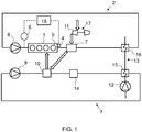
- Embodiments of the invention are described below in more detail with reference to the accompanying drawing, which shows schematically a piston engine together with cooling circuits.
- In the figure is shown schematically a cooling system of a piston engine 1. The engine 1 is a large internal combustion engine, such as a main or an auxiliary engine of a ship or an engine that is used at a power plant for producing electricity. In the figure is shown an engine with four
cylinders 5, but the engine 1 can comprise any reasonable number ofcylinders 5, which are arranged, for instance, in line or in a V-configuration. - The cooling system of the engine 1 comprises two
separate cooling circuits cooling circuits temperature cooling circuit 2 and the other one is a lowtemperature cooling circuit 3, in which the temperature of the cooling medium is lower than in the hightemperature cooling circuit 2. Bothcooling circuits temperature cooling circuit 2 is typically around 90-105 °C and in the lowtemperature cooling circuit 3 35-50 °C. The cooling medium in thecooling circuits cooling medium circuits pump external cooling circuit 13, which transfers heat away from the hightemperature cooling circuit 2 and the lowtemperature cooling circuit 3. However, it would also be possible to provide the high temperature and the lowtemperature cooling circuits external cooling circuit 13 may not be needed. Theexternal cooling circuit 13 is provided with apump 12 for circulating the cooling medium in thecircuit 13. Theexternal cooling circuit 13 also comprises a lowtemperature heat exchanger 15 for transferring heat from the lowtemperature cooling circuit 3 to theexternal cooling circuit 13 and a hightemperature heat exchanger 16 for transferring heat from the hightemperature cooling circuit 2 to theexternal cooling circuit 13. - In the high
temperature cooling circuit 2, the cooling medium flows from thepump 8 to the engine 1, where heat is transferred from the cylinder liners and the cylinder heads of the engine 1 to the cooling medium. From the engine 1, the cooling medium of the hightemperature cooling circuit 2 flows to a firstcharge air cooler 7. The firstcharge air cooler 7 is connected to acompressor 11 of aturbocharger 17. In the firstcharge air cooler 7, heat is transferred from the charge air to the cooling medium of the hightemperature cooling circuit 2. If the engine 1 is provided with two-stage turbocharging, the firstcharge air cooler 7 could also be arranged between the two stages. From the firstcharge air cooler 7, the cooling medium flows to the hightemperature heat exchanger 16, where heat is transferred from the cooling medium of the hightemperature cooling circuit 2 to the cooling medium of theexternal cooling circuit 13. The cooling medium of the hightemperature cooling circuit 2 then returns to thepump 8 at a lower temperature. - In the low
temperature cooling circuit 3, the cooling medium flows from thepump 9 to a secondcharge air cooler 10. The secondcharge air cooler 10 is arranged downstream from the firstcharge air cooler 7 in the flow direction of the charge air. In the secondcharge air cooler 10, heat is transferred from the charge air to the cooling medium of the lowtemperature cooling circuit 3. From the secondcharge air cooler 10, the charge air is conducted into the intake manifold of the engine 1. The cooling medium is conducted from the secondcharge air cooler 10 to alube oil cooler 14, where heat is transferred from the lube oil of the engine 1 to the cooling medium of the lowtemperature cooling circuit 3. From thelube oil cooler 14, the cooling medium flows to the lowtemperature heat exchanger 15, where heat is transferred from the cooling medium of the lowtemperature cooling circuit 3 to theexternal cooling circuit 13. - Each
cylinder 5 of the engine 1 is provided with a cylinder liner, which together with a cylinder head and a piston defines a combustion chamber. Eachcylinder 5 of the engine 1 is thus provided with an own cylinder head, which closes one end of thecylinder 5. To seal the joint between the cylinder liner and the cylinder head, a head gasket is arranged between an end surface of the cylinder liner and the cylinder head. The head gasket is an important component, which on the one hand prevents the combustion products from leaking from thecylinder 5, and on the other hand prevents cooling medium leakage into thecylinder 5. - A defective head gasket has several consequences. For instance, since the combustion products can leak out of the
cylinder 5, the power output of theaffected cylinder 5 is lower than the power output of theother cylinders 5. The uneven power output of thecylinders 5 increases torsional vibrations of the crankshaft of the engine 1. Thecylinders 5 of the engine 1 are surrounded by cooling medium channels. Therefore, a defective head gasket allows leaking of the combustion products into the cooling system, which causes pressure increase in the cooling system. The cooling medium can also leak into thecylinder 5 with a defective head gasket. The cooling medium in thecylinder 5 lowers the temperature in thatcylinder 5 and can in the worst case cause a water stroke, which can cause significant damage to the engine 1. - To detect failure of a head gasket, the engine 1 comprises means for monitoring the pressure of a cooling liquid of the engine 1. The engine 1 is further provided with means for monitoring torsional vibrations of the crankshaft of the engine 1. The pressure of the cooling liquid and the torsional vibrations can thus be monitored. Limit values are determined for both the cooling liquid pressure and the torsional vibrations. The monitored values can be compared to the limit values, and if both limit values are exceeded, it is an indication of a defective head gasket. When a defective head gasket is detected, an alarm can be triggered or the engine 1 can be automatically shut down to prevent damages.
- In the embodiment of the figure, the means for monitoring the pressure of a cooling liquid comprise a
pressure sensor 6, which is arranged to measure pressure in a cooling circuit. In the embodiment of the figure, thepressure sensor 6 measures the pressure in the hightemperature cooling circuit 2. Thepressure sensor 6 is arranged between thepump 8 of the hightemperature cooling circuit 2 and the engine 1. During normal operation of the engine 1, the pressure in the hightemperature cooling circuit 2 is typically in the range of 4 to 6 bar. Depending on the engine 1, the cooling liquid pressure could also be monitored from a low-temperature cooling circuit 3. If the hightemperature cooling circuit 2 is fully separated from the lowtemperature cooling circuit 3 and only the hightemperature cooling circuit 2 is used for cooling thecylinders 5 of the engine 1, a defective head gasket does not affect the pressure in the lowtemperature cooling circuit 2. In that case, the pressure needs to be monitored from the hightemperature cooling circuit 2. Thepressure sensor 6 could be anywhere in the hightemperature cooling circuit 2. - Torsional vibrations are caused by fluctuating torque and mean variations in the angular velocity of the crankshaft. Torsional vibrations are present even during normal running of the engine, since the torque produced by the combustion is not constant. However, the level of the torsional vibrations is not constant but it is affected by several different factors. For instance, changes in the engine load and misfiring in a
cylinder 5 increase torsional vibrations. The level of torsional vibrations is usually expressed in millidegrees (mdeg). Torsional vibrations can be measured, for instance, using shaft encoders attached to the crankshaft or with laser vibrometers. One way of determining torsional vibrations is to use magnetic pickup sensors for measuring the speed of the flywheel of the engine 1 and to use the data to calculate the torsional vibrations. In the embodiment of the figure, the means for monitoring torsional vibrations of the engine 1 comprises a shaft encoder 4. - During operation of the engine 1, the pressure of the cooling liquid and the torsional vibrations of the crankshaft of the engine 1 are continuously monitored. The measurement data is sent to a
control unit 18. Thecontrol unit 18 compares the measured cooling liquid pressure to a predetermined limit value and the measured torsional vibrations to another predetermined limit value. In case both limit values are exceeded, a defective head gasket is diagnosed. When thecontrol unit 18 diagnoses a defective head gasket, it can either trigger an alarm or automatically shut down the engine 1. The limit value for the cooling liquid pressure can be set to be, for instance, 10 to 50 percent or 1 to 3 bar above the normal operating pressure in the measurement point. For instance, if the pressure of the cooling liquid in the hightemperature cooling circuit 2 during the normal operation of the engine 1 is 5 bar, the limit value could be 6 bar. - The normal level of torsional vibrations depends on several factors, such as the number of
cylinders 5, rated speed and rated power of the engine 1 and it can also depend on the use of the engine 1. For instance, if the engine 1 is used for driving a generator, the characteristics of the generator and the clutch between the engine 1 and the generator affect the level of the torsional vibrations. Therefore, the limit value for the torsional vibrations needs to be individually determined for each engine type and possibly also for each different application. As an example, the limit value for the torsional vibrations could be 25 to 100 percent or 50 to 250 millidegrees above the maximum value of the torsional vibrations during steady state operation of the engine 1. For instance, if the highest torsional vibration values measured during steady state operation of the engine are 200 mdeg and a broken head gasket typically raises the level above 300 mdeg, the limit value could be 250 mdeg. - During start of the engine 1, the amplitude of the torsional vibrations can be significant, even though the head gaskets are not defective. Therefore, the
control unit 18 can be configured to diagnose a defective head gasket only after the engine 1 has reached a certain rotation speed. A limit value is thus set for the rotation speed, and below the predetermined limit value, the torsional vibrations of the engine 1 are ignored. The limit value can be, for instance, the idle speed of the engine +/- 50 rpm. - In addition to defective head gaskets, possible causes for increased cooling medium pressure are faulty thermostats and valves in the cooling system and increase of the cooling medium temperature. Torsional vibrations increase for example when a variable intake valve closing function is switched on or when the engine load suddenly increases. There are thus several factors increasing either the pressure of the cooling medium or the torsional vibrations, but most of the factors affect only one of the monitored parameters. Therefore, when both the cooling medium temperature and the torsional vibrations increase, it is likely that the increase is caused by a defective head gasket.
- Since both the cooling medium pressure and the torsional vibrations are monitored and used for diagnosing a defective head gasket, the respective limit values can be set lower than in a case where only one parameter is monitored. A defective head gasket can thus be detected earlier. Also, the use of two parameters reduces the likelihood of false alarms.
- It will be appreciated by a person skilled in the art that the invention is not limited to the embodiments described above, but may vary within the scope of the appended claims. For instance, although an engine with two cooling circuits is shown in the drawing, the engine could also be provided with a single cooling circuit.
Claims (10)
- A method for operating a piston engine (1), the method comprising the steps of- monitoring the pressure of a cooling liquid that is used for cooling the cylinders (5) of the engine (1),- monitoring torsional vibrations of the crankshaft of the engine (1),- comparing the measured cooling liquid pressure to a predetermined limit value,- comparing the measured torsional vibrations to a predetermined limit value, and- in case the measured cooling liquid pressure exceeds its predetermined limit value and the measured torsional vibrations exceed their predetermined limit value, diagnosing a leaking head gasket.
- A method according to claim 1, wherein the pressure of the cooling liquid is monitored from a high temperature cooling circuit (2).
- A method according to claim 1 or 2, wherein the engine (1) is shut down in case a leaking head gasket is diagnosed.
- A method according to any of the preceding claims, wherein a leaking head gasket is diagnosed only in case the rotation speed of the engine (1) is above a predetermined limit value.
- A method according to any of the preceding claims, wherein the limit value for the cooling liquid pressure is set to be 10-50 percent above the normal operating pressure in the measurement point.
- A method according to any of the preceding claims, wherein the limit value for the cooling liquid pressure is set to be 1-3 bar above the normal operating pressure in the measurement point.
- A method according to any of the preceding claims, wherein the limit value for the torsional vibrations is set to be 0.05-0.25 degrees above the maximum torsional vibration values measured during steady state operation of the engine (1).
- A method according to any of the preceding claims, wherein the limit value for the torsional vibrations is set to be 25-100 percent above the maximum torsional vibration values measured during steady state operation of the engine (1).
- An arrangement for detecting failure of a head gasket of a piston engine (1), the arrangement comprising- means (6) for monitoring the pressure of a cooling liquid that is used for cooling the cylinders (5) of the engine (1),- means (4) for monitoring torsional vibrations of the crankshaft of the engine (1), and- a control unit (18) that is configured to compare the measured cooling liquid pressure to a predetermined limit value and the measured torsional vibrations to another predetermined limit value and to diagnose a leaking head gasket in case the measured cooling liquid pressure exceeds its predetermined limit value and the measured torsional vibrations exceed their predetermined limit value.
- An arrangement according to claim 9, wherein the means (5) for monitoring the pressure of the cooling liquid are arranged to monitor the pressure in a high temperature cooling circuit (2).
Applications Claiming Priority (1)
| Application Number | Priority Date | Filing Date | Title |
|---|---|---|---|
| PCT/FI2015/050565 WO2017037328A1 (en) | 2015-09-01 | 2015-09-01 | Method for operating a piston engine and arrangement for detecting failure of a head gasket |
Publications (2)
| Publication Number | Publication Date |
|---|---|
| EP3344969A1 EP3344969A1 (en) | 2018-07-11 |
| EP3344969B1 true EP3344969B1 (en) | 2020-01-29 |
Family
ID=54147219
Family Applications (1)
| Application Number | Title | Priority Date | Filing Date |
|---|---|---|---|
| EP15766182.8A Active EP3344969B1 (en) | 2015-09-01 | 2015-09-01 | Method for operating a piston engine and arrangement for detecting failure of a head gasket |
Country Status (4)
| Country | Link |
|---|---|
| EP (1) | EP3344969B1 (en) |
| KR (1) | KR102048644B1 (en) |
| CN (1) | CN107923817B (en) |
| WO (1) | WO2017037328A1 (en) |
Cited By (1)
| Publication number | Priority date | Publication date | Assignee | Title |
|---|---|---|---|---|
| WO2022180296A1 (en) * | 2021-02-23 | 2022-09-01 | Wärtsilä Finland Oy | Torsional vibration model |
Family Cites Families (9)
| Publication number | Priority date | Publication date | Assignee | Title |
|---|---|---|---|---|
| US4682493A (en) * | 1983-09-15 | 1987-07-28 | Dakten Products Corp. | Cooling system monitor |
| KR100203178B1 (en) * | 1996-12-09 | 1999-06-15 | 류정열 | Crankshaft Torsional Vibration Measuring Device |
| KR100367180B1 (en) * | 2000-11-09 | 2003-01-09 | 기아자동차주식회사 | Device for confirmation gas leak of head gasket the using heat exchanger |
| CN201016835Y (en) * | 2006-12-30 | 2008-02-06 | 广西玉柴机器股份有限公司 | Engine cylinder cover pad sealing performance detecting apparatus |
| US20120318040A1 (en) * | 2011-06-16 | 2012-12-20 | Clifford Kratzet | System and method of detecting head gasket degradation |
| CN202735034U (en) * | 2012-07-26 | 2013-02-13 | 广西玉柴机器股份有限公司 | Cylinder cover leakage testing tool |
| KR101416448B1 (en) * | 2012-11-28 | 2014-07-10 | 동아공업 주식회사 | A performance testing apparatus of cylinder head gasket using steam and oil pressure |
| CN103234739B (en) * | 2013-04-01 | 2016-08-31 | 中国北方发动机研究所(天津) | A kind of cylinder head thermal fatigue test apparatus and test method |
| US20150177103A1 (en) * | 2013-12-20 | 2015-06-25 | Cecil L. Brown | Apparatus and method for determination of cylinder head gasket joint failure in a running engine |
-
2015
- 2015-09-01 EP EP15766182.8A patent/EP3344969B1/en active Active
- 2015-09-01 CN CN201580082798.1A patent/CN107923817B/en active Active
- 2015-09-01 WO PCT/FI2015/050565 patent/WO2017037328A1/en not_active Ceased
- 2015-09-01 KR KR1020187006963A patent/KR102048644B1/en active Active
Non-Patent Citations (1)
| Title |
|---|
| None * |
Cited By (1)
| Publication number | Priority date | Publication date | Assignee | Title |
|---|---|---|---|---|
| WO2022180296A1 (en) * | 2021-02-23 | 2022-09-01 | Wärtsilä Finland Oy | Torsional vibration model |
Also Published As
| Publication number | Publication date |
|---|---|
| CN107923817A (en) | 2018-04-17 |
| CN107923817B (en) | 2019-08-30 |
| EP3344969A1 (en) | 2018-07-11 |
| KR102048644B1 (en) | 2019-11-25 |
| KR20180034662A (en) | 2018-04-04 |
| WO2017037328A1 (en) | 2017-03-09 |
Similar Documents
| Publication | Publication Date | Title |
|---|---|---|
| US10450985B2 (en) | On-board diagnostics for an opposed-piston engine equipped with a supercharger | |
| CN102893011B (en) | Method for determining EGR rate of internal combustion engine and control device for internal combustion engine | |
| US20110098883A1 (en) | Method and device for diagnosing a coolant pump for an internal combustion engine | |
| CN101333957B (en) | Ship diesel closed type cooling water system risk prealarming method | |
| WO2017110242A1 (en) | Fault detection device for internal combustion engine | |
| Mohamed | Performance analysis and condition monitoring of ICE piston-ring based on combustion and thermal characteristics | |
| JP2008208751A (en) | Deterioration degree diagnostic system of engine component | |
| CN101512128A (en) | System and method for detecting impaired operation of a turbocharger of an internal combustion engine | |
| JP2005264853A (en) | Internal combustion engine | |
| EP3344969B1 (en) | Method for operating a piston engine and arrangement for detecting failure of a head gasket | |
| US8428809B2 (en) | Multi-step valve lift failure mode detection | |
| CN105587407A (en) | Method for preventing engine cylinder scoring | |
| JP4148168B2 (en) | Internal combustion engine | |
| US6055852A (en) | Method and apparatus for estimation of relative cylinder compression balance by cranking speed analysis | |
| CN104769274B (en) | The liquid detecting system of explosive motor | |
| JP2020139812A (en) | Gas leakage detection system in internal combustion engine | |
| JP4825292B2 (en) | Abnormality detection method for marine diesel engines | |
| KR102689264B1 (en) | Diagnosis method of the gas-sealed condition of cylinders in a marine 2-stroke diesel engine | |
| JP7397695B2 (en) | Determination device, ship-to-land communication system, and determination method | |
| JP2013032726A (en) | Abnormality diagnostic device for internal combustion engine | |
| Tsitsilonis et al. | A modelling approach for predicting marine engines shaft dynamics | |
| RU2458331C1 (en) | Method of evaluating four-stroke piston ice sleeve assembly | |
| CN108071506A (en) | For diagnosing the method and apparatus of the refrigerant injection device of explosive motor | |
| Drewing et al. | Analysis of changes in the angular velocity of the crankshaft of the marine engine for diagnosing the wear and location the failure of the fuel injection system | |
| WO2022202431A1 (en) | Supercharger abnormality determination device and supercharger abnormality determination method |
Legal Events
| Date | Code | Title | Description |
|---|---|---|---|
| STAA | Information on the status of an ep patent application or granted ep patent |
Free format text: STATUS: THE INTERNATIONAL PUBLICATION HAS BEEN MADE |
|
| PUAI | Public reference made under article 153(3) epc to a published international application that has entered the european phase |
Free format text: ORIGINAL CODE: 0009012 |
|
| STAA | Information on the status of an ep patent application or granted ep patent |
Free format text: STATUS: REQUEST FOR EXAMINATION WAS MADE |
|
| 17P | Request for examination filed |
Effective date: 20180227 |
|
| AK | Designated contracting states |
Kind code of ref document: A1 Designated state(s): AL AT BE BG CH CY CZ DE DK EE ES FI FR GB GR HR HU IE IS IT LI LT LU LV MC MK MT NL NO PL PT RO RS SE SI SK SM TR |
|
| AX | Request for extension of the european patent |
Extension state: BA ME |
|
| RAP1 | Party data changed (applicant data changed or rights of an application transferred) |
Owner name: WAERTSILAE FINLAND OY |
|
| DAV | Request for validation of the european patent (deleted) | ||
| DAX | Request for extension of the european patent (deleted) | ||
| RIC1 | Information provided on ipc code assigned before grant |
Ipc: G01M 15/09 20060101ALI20190319BHEP Ipc: F01P 11/18 20060101ALI20190319BHEP Ipc: F02D 41/14 20060101ALI20190319BHEP Ipc: F02D 41/22 20060101ALI20190319BHEP Ipc: G01M 15/12 20060101ALI20190319BHEP Ipc: G01M 15/05 20060101AFI20190319BHEP |
|
| GRAP | Despatch of communication of intention to grant a patent |
Free format text: ORIGINAL CODE: EPIDOSNIGR1 |
|
| STAA | Information on the status of an ep patent application or granted ep patent |
Free format text: STATUS: GRANT OF PATENT IS INTENDED |
|
| INTG | Intention to grant announced |
Effective date: 20190522 |
|
| GRAJ | Information related to disapproval of communication of intention to grant by the applicant or resumption of examination proceedings by the epo deleted |
Free format text: ORIGINAL CODE: EPIDOSDIGR1 |
|
| STAA | Information on the status of an ep patent application or granted ep patent |
Free format text: STATUS: REQUEST FOR EXAMINATION WAS MADE |
|
| GRAP | Despatch of communication of intention to grant a patent |
Free format text: ORIGINAL CODE: EPIDOSNIGR1 |
|
| STAA | Information on the status of an ep patent application or granted ep patent |
Free format text: STATUS: GRANT OF PATENT IS INTENDED |
|
| INTG | Intention to grant announced |
Effective date: 20190829 |
|
| GRAS | Grant fee paid |
Free format text: ORIGINAL CODE: EPIDOSNIGR3 |
|
| GRAA | (expected) grant |
Free format text: ORIGINAL CODE: 0009210 |
|
| STAA | Information on the status of an ep patent application or granted ep patent |
Free format text: STATUS: THE PATENT HAS BEEN GRANTED |
|
| AK | Designated contracting states |
Kind code of ref document: B1 Designated state(s): AL AT BE BG CH CY CZ DE DK EE ES FI FR GB GR HR HU IE IS IT LI LT LU LV MC MK MT NL NO PL PT RO RS SE SI SK SM TR |
|
| REG | Reference to a national code |
Ref country code: GB Ref legal event code: FG4D |
|
| REG | Reference to a national code |
Ref country code: CH Ref legal event code: EP |
|
| REG | Reference to a national code |
Ref country code: AT Ref legal event code: REF Ref document number: 1228846 Country of ref document: AT Kind code of ref document: T Effective date: 20200215 |
|
| REG | Reference to a national code |
Ref country code: IE Ref legal event code: FG4D |
|
| REG | Reference to a national code |
Ref country code: DE Ref legal event code: R096 Ref document number: 602015046058 Country of ref document: DE |
|
| REG | Reference to a national code |
Ref country code: NO Ref legal event code: T2 Effective date: 20200129 |
|
| REG | Reference to a national code |
Ref country code: NL Ref legal event code: MP Effective date: 20200129 |
|
| PG25 | Lapsed in a contracting state [announced via postgrant information from national office to epo] |
Ref country code: PT Free format text: LAPSE BECAUSE OF FAILURE TO SUBMIT A TRANSLATION OF THE DESCRIPTION OR TO PAY THE FEE WITHIN THE PRESCRIBED TIME-LIMIT Effective date: 20200621 Ref country code: FI Free format text: LAPSE BECAUSE OF FAILURE TO SUBMIT A TRANSLATION OF THE DESCRIPTION OR TO PAY THE FEE WITHIN THE PRESCRIBED TIME-LIMIT Effective date: 20200129 Ref country code: RS Free format text: LAPSE BECAUSE OF FAILURE TO SUBMIT A TRANSLATION OF THE DESCRIPTION OR TO PAY THE FEE WITHIN THE PRESCRIBED TIME-LIMIT Effective date: 20200129 |
|
| REG | Reference to a national code |
Ref country code: LT Ref legal event code: MG4D |
|
| PG25 | Lapsed in a contracting state [announced via postgrant information from national office to epo] |
Ref country code: LV Free format text: LAPSE BECAUSE OF FAILURE TO SUBMIT A TRANSLATION OF THE DESCRIPTION OR TO PAY THE FEE WITHIN THE PRESCRIBED TIME-LIMIT Effective date: 20200129 Ref country code: SE Free format text: LAPSE BECAUSE OF FAILURE TO SUBMIT A TRANSLATION OF THE DESCRIPTION OR TO PAY THE FEE WITHIN THE PRESCRIBED TIME-LIMIT Effective date: 20200129 Ref country code: IS Free format text: LAPSE BECAUSE OF FAILURE TO SUBMIT A TRANSLATION OF THE DESCRIPTION OR TO PAY THE FEE WITHIN THE PRESCRIBED TIME-LIMIT Effective date: 20200529 Ref country code: HR Free format text: LAPSE BECAUSE OF FAILURE TO SUBMIT A TRANSLATION OF THE DESCRIPTION OR TO PAY THE FEE WITHIN THE PRESCRIBED TIME-LIMIT Effective date: 20200129 Ref country code: BG Free format text: LAPSE BECAUSE OF FAILURE TO SUBMIT A TRANSLATION OF THE DESCRIPTION OR TO PAY THE FEE WITHIN THE PRESCRIBED TIME-LIMIT Effective date: 20200429 Ref country code: GR Free format text: LAPSE BECAUSE OF FAILURE TO SUBMIT A TRANSLATION OF THE DESCRIPTION OR TO PAY THE FEE WITHIN THE PRESCRIBED TIME-LIMIT Effective date: 20200430 |
|
| PG25 | Lapsed in a contracting state [announced via postgrant information from national office to epo] |
Ref country code: NL Free format text: LAPSE BECAUSE OF FAILURE TO SUBMIT A TRANSLATION OF THE DESCRIPTION OR TO PAY THE FEE WITHIN THE PRESCRIBED TIME-LIMIT Effective date: 20200129 |
|
| PG25 | Lapsed in a contracting state [announced via postgrant information from national office to epo] |
Ref country code: EE Free format text: LAPSE BECAUSE OF FAILURE TO SUBMIT A TRANSLATION OF THE DESCRIPTION OR TO PAY THE FEE WITHIN THE PRESCRIBED TIME-LIMIT Effective date: 20200129 Ref country code: SM Free format text: LAPSE BECAUSE OF FAILURE TO SUBMIT A TRANSLATION OF THE DESCRIPTION OR TO PAY THE FEE WITHIN THE PRESCRIBED TIME-LIMIT Effective date: 20200129 Ref country code: RO Free format text: LAPSE BECAUSE OF FAILURE TO SUBMIT A TRANSLATION OF THE DESCRIPTION OR TO PAY THE FEE WITHIN THE PRESCRIBED TIME-LIMIT Effective date: 20200129 Ref country code: LT Free format text: LAPSE BECAUSE OF FAILURE TO SUBMIT A TRANSLATION OF THE DESCRIPTION OR TO PAY THE FEE WITHIN THE PRESCRIBED TIME-LIMIT Effective date: 20200129 Ref country code: ES Free format text: LAPSE BECAUSE OF FAILURE TO SUBMIT A TRANSLATION OF THE DESCRIPTION OR TO PAY THE FEE WITHIN THE PRESCRIBED TIME-LIMIT Effective date: 20200129 Ref country code: CZ Free format text: LAPSE BECAUSE OF FAILURE TO SUBMIT A TRANSLATION OF THE DESCRIPTION OR TO PAY THE FEE WITHIN THE PRESCRIBED TIME-LIMIT Effective date: 20200129 Ref country code: SK Free format text: LAPSE BECAUSE OF FAILURE TO SUBMIT A TRANSLATION OF THE DESCRIPTION OR TO PAY THE FEE WITHIN THE PRESCRIBED TIME-LIMIT Effective date: 20200129 Ref country code: DK Free format text: LAPSE BECAUSE OF FAILURE TO SUBMIT A TRANSLATION OF THE DESCRIPTION OR TO PAY THE FEE WITHIN THE PRESCRIBED TIME-LIMIT Effective date: 20200129 |
|
| REG | Reference to a national code |
Ref country code: DE Ref legal event code: R097 Ref document number: 602015046058 Country of ref document: DE |
|
| PLBE | No opposition filed within time limit |
Free format text: ORIGINAL CODE: 0009261 |
|
| STAA | Information on the status of an ep patent application or granted ep patent |
Free format text: STATUS: NO OPPOSITION FILED WITHIN TIME LIMIT |
|
| 26N | No opposition filed |
Effective date: 20201030 |
|
| PG25 | Lapsed in a contracting state [announced via postgrant information from national office to epo] |
Ref country code: IT Free format text: LAPSE BECAUSE OF FAILURE TO SUBMIT A TRANSLATION OF THE DESCRIPTION OR TO PAY THE FEE WITHIN THE PRESCRIBED TIME-LIMIT Effective date: 20200129 |
|
| PG25 | Lapsed in a contracting state [announced via postgrant information from national office to epo] |
Ref country code: SI Free format text: LAPSE BECAUSE OF FAILURE TO SUBMIT A TRANSLATION OF THE DESCRIPTION OR TO PAY THE FEE WITHIN THE PRESCRIBED TIME-LIMIT Effective date: 20200129 Ref country code: PL Free format text: LAPSE BECAUSE OF FAILURE TO SUBMIT A TRANSLATION OF THE DESCRIPTION OR TO PAY THE FEE WITHIN THE PRESCRIBED TIME-LIMIT Effective date: 20200129 |
|
| REG | Reference to a national code |
Ref country code: CH Ref legal event code: PL |
|
| GBPC | Gb: european patent ceased through non-payment of renewal fee |
Effective date: 20200901 |
|
| REG | Reference to a national code |
Ref country code: BE Ref legal event code: MM Effective date: 20200930 |
|
| PG25 | Lapsed in a contracting state [announced via postgrant information from national office to epo] |
Ref country code: LU Free format text: LAPSE BECAUSE OF NON-PAYMENT OF DUE FEES Effective date: 20200901 |
|
| PG25 | Lapsed in a contracting state [announced via postgrant information from national office to epo] |
Ref country code: FR Free format text: LAPSE BECAUSE OF NON-PAYMENT OF DUE FEES Effective date: 20200930 |
|
| PG25 | Lapsed in a contracting state [announced via postgrant information from national office to epo] |
Ref country code: GB Free format text: LAPSE BECAUSE OF NON-PAYMENT OF DUE FEES Effective date: 20200901 Ref country code: LI Free format text: LAPSE BECAUSE OF NON-PAYMENT OF DUE FEES Effective date: 20200930 Ref country code: IE Free format text: LAPSE BECAUSE OF NON-PAYMENT OF DUE FEES Effective date: 20200901 Ref country code: BE Free format text: LAPSE BECAUSE OF NON-PAYMENT OF DUE FEES Effective date: 20200930 Ref country code: CH Free format text: LAPSE BECAUSE OF NON-PAYMENT OF DUE FEES Effective date: 20200930 |
|
| REG | Reference to a national code |
Ref country code: AT Ref legal event code: UEP Ref document number: 1228846 Country of ref document: AT Kind code of ref document: T Effective date: 20200129 |
|
| PG25 | Lapsed in a contracting state [announced via postgrant information from national office to epo] |
Ref country code: TR Free format text: LAPSE BECAUSE OF FAILURE TO SUBMIT A TRANSLATION OF THE DESCRIPTION OR TO PAY THE FEE WITHIN THE PRESCRIBED TIME-LIMIT Effective date: 20200129 Ref country code: MT Free format text: LAPSE BECAUSE OF FAILURE TO SUBMIT A TRANSLATION OF THE DESCRIPTION OR TO PAY THE FEE WITHIN THE PRESCRIBED TIME-LIMIT Effective date: 20200129 Ref country code: CY Free format text: LAPSE BECAUSE OF FAILURE TO SUBMIT A TRANSLATION OF THE DESCRIPTION OR TO PAY THE FEE WITHIN THE PRESCRIBED TIME-LIMIT Effective date: 20200129 |
|
| PG25 | Lapsed in a contracting state [announced via postgrant information from national office to epo] |
Ref country code: MK Free format text: LAPSE BECAUSE OF FAILURE TO SUBMIT A TRANSLATION OF THE DESCRIPTION OR TO PAY THE FEE WITHIN THE PRESCRIBED TIME-LIMIT Effective date: 20200129 Ref country code: MC Free format text: LAPSE BECAUSE OF FAILURE TO SUBMIT A TRANSLATION OF THE DESCRIPTION OR TO PAY THE FEE WITHIN THE PRESCRIBED TIME-LIMIT Effective date: 20200129 Ref country code: AL Free format text: LAPSE BECAUSE OF FAILURE TO SUBMIT A TRANSLATION OF THE DESCRIPTION OR TO PAY THE FEE WITHIN THE PRESCRIBED TIME-LIMIT Effective date: 20200129 |
|
| PGFP | Annual fee paid to national office [announced via postgrant information from national office to epo] |
Ref country code: DE Payment date: 20250919 Year of fee payment: 11 |
|
| PGFP | Annual fee paid to national office [announced via postgrant information from national office to epo] |
Ref country code: NO Payment date: 20250923 Year of fee payment: 11 |
|
| PGFP | Annual fee paid to national office [announced via postgrant information from national office to epo] |
Ref country code: AT Payment date: 20250919 Year of fee payment: 11 |