EP3344854B1 - Flow control device for rotating flow supply system - Google Patents
Flow control device for rotating flow supply system Download PDFInfo
- Publication number
- EP3344854B1 EP3344854B1 EP16766093.5A EP16766093A EP3344854B1 EP 3344854 B1 EP3344854 B1 EP 3344854B1 EP 16766093 A EP16766093 A EP 16766093A EP 3344854 B1 EP3344854 B1 EP 3344854B1
- Authority
- EP
- European Patent Office
- Prior art keywords
- rotor
- control device
- flow control
- rotor blade
- junction
- Prior art date
- Legal status (The legal status is an assumption and is not a legal conclusion. Google has not performed a legal analysis and makes no representation as to the accuracy of the status listed.)
- Not-in-force
Links
Images




Classifications
-
- F—MECHANICAL ENGINEERING; LIGHTING; HEATING; WEAPONS; BLASTING
- F01—MACHINES OR ENGINES IN GENERAL; ENGINE PLANTS IN GENERAL; STEAM ENGINES
- F01D—NON-POSITIVE DISPLACEMENT MACHINES OR ENGINES, e.g. STEAM TURBINES
- F01D11/00—Preventing or minimising internal leakage of working-fluid, e.g. between stages
- F01D11/005—Sealing means between non relatively rotating elements
- F01D11/006—Sealing the gap between rotor blades or blades and rotor
-
- F—MECHANICAL ENGINEERING; LIGHTING; HEATING; WEAPONS; BLASTING
- F01—MACHINES OR ENGINES IN GENERAL; ENGINE PLANTS IN GENERAL; STEAM ENGINES
- F01D—NON-POSITIVE DISPLACEMENT MACHINES OR ENGINES, e.g. STEAM TURBINES
- F01D5/00—Blades; Blade-carrying members; Heating, heat-insulating, cooling or antivibration means on the blades or the members
- F01D5/12—Blades
- F01D5/14—Form or construction
- F01D5/18—Hollow blades, i.e. blades with cooling or heating channels or cavities; Heating, heat-insulating or cooling means on blades
- F01D5/187—Convection cooling
-
- F—MECHANICAL ENGINEERING; LIGHTING; HEATING; WEAPONS; BLASTING
- F01—MACHINES OR ENGINES IN GENERAL; ENGINE PLANTS IN GENERAL; STEAM ENGINES
- F01D—NON-POSITIVE DISPLACEMENT MACHINES OR ENGINES, e.g. STEAM TURBINES
- F01D5/00—Blades; Blade-carrying members; Heating, heat-insulating, cooling or antivibration means on the blades or the members
- F01D5/12—Blades
- F01D5/14—Form or construction
- F01D5/18—Hollow blades, i.e. blades with cooling or heating channels or cavities; Heating, heat-insulating or cooling means on blades
-
- F—MECHANICAL ENGINEERING; LIGHTING; HEATING; WEAPONS; BLASTING
- F01—MACHINES OR ENGINES IN GENERAL; ENGINE PLANTS IN GENERAL; STEAM ENGINES
- F01D—NON-POSITIVE DISPLACEMENT MACHINES OR ENGINES, e.g. STEAM TURBINES
- F01D5/00—Blades; Blade-carrying members; Heating, heat-insulating, cooling or antivibration means on the blades or the members
- F01D5/30—Fixing blades to rotors; Blade roots ; Blade spacers
- F01D5/3007—Fixing blades to rotors; Blade roots ; Blade spacers of axial insertion type
-
- F—MECHANICAL ENGINEERING; LIGHTING; HEATING; WEAPONS; BLASTING
- F05—INDEXING SCHEMES RELATING TO ENGINES OR PUMPS IN VARIOUS SUBCLASSES OF CLASSES F01-F04
- F05D—INDEXING SCHEME FOR ASPECTS RELATING TO NON-POSITIVE-DISPLACEMENT MACHINES OR ENGINES, GAS-TURBINES OR JET-PROPULSION PLANTS
- F05D2220/00—Application
- F05D2220/30—Application in turbines
- F05D2220/32—Application in turbines in gas turbines
-
- F—MECHANICAL ENGINEERING; LIGHTING; HEATING; WEAPONS; BLASTING
- F05—INDEXING SCHEMES RELATING TO ENGINES OR PUMPS IN VARIOUS SUBCLASSES OF CLASSES F01-F04
- F05D—INDEXING SCHEME FOR ASPECTS RELATING TO NON-POSITIVE-DISPLACEMENT MACHINES OR ENGINES, GAS-TURBINES OR JET-PROPULSION PLANTS
- F05D2230/00—Manufacture
- F05D2230/60—Assembly methods
-
- F—MECHANICAL ENGINEERING; LIGHTING; HEATING; WEAPONS; BLASTING
- F05—INDEXING SCHEMES RELATING TO ENGINES OR PUMPS IN VARIOUS SUBCLASSES OF CLASSES F01-F04
- F05D—INDEXING SCHEME FOR ASPECTS RELATING TO NON-POSITIVE-DISPLACEMENT MACHINES OR ENGINES, GAS-TURBINES OR JET-PROPULSION PLANTS
- F05D2240/00—Components
- F05D2240/20—Rotors
- F05D2240/30—Characteristics of rotor blades, i.e. of any element transforming dynamic fluid energy to or from rotational energy and being attached to a rotor
-
- F—MECHANICAL ENGINEERING; LIGHTING; HEATING; WEAPONS; BLASTING
- F05—INDEXING SCHEMES RELATING TO ENGINES OR PUMPS IN VARIOUS SUBCLASSES OF CLASSES F01-F04
- F05D—INDEXING SCHEME FOR ASPECTS RELATING TO NON-POSITIVE-DISPLACEMENT MACHINES OR ENGINES, GAS-TURBINES OR JET-PROPULSION PLANTS
- F05D2240/00—Components
- F05D2240/55—Seals
- F05D2240/56—Brush seals
-
- F—MECHANICAL ENGINEERING; LIGHTING; HEATING; WEAPONS; BLASTING
- F05—INDEXING SCHEMES RELATING TO ENGINES OR PUMPS IN VARIOUS SUBCLASSES OF CLASSES F01-F04
- F05D—INDEXING SCHEME FOR ASPECTS RELATING TO NON-POSITIVE-DISPLACEMENT MACHINES OR ENGINES, GAS-TURBINES OR JET-PROPULSION PLANTS
- F05D2260/00—Function
- F05D2260/20—Heat transfer, e.g. cooling
Definitions
- the invention relates to a flow control device for a rotating flow supply system, such as a rotating constant flow supply system used in a rotor and blade assembly in a gas turbine.
- Gas turbines include numerous components, such as, for example, a combustor for mixing air and fuel for ignition, a turbine blade and rotor assembly for producing power, and a flow supply system for supplying cooling fluid/gas ("coolant") to turbine blade and rotor components when the gas turbine is in operation.
- Gas turbine combustors often operate at temperatures that can exceed 1371,1 °C (2,500 degrees Fahrenheit), and as such, the turbine components, including the blade and rotor components, are exposed to these high temperatures.
- the flow supply system is useful for cooling the blade and rotor components during operation of the gas turbine to help maintain durability requirements of these components.
- Turbine cooling and leakage air is one form of coolant which may be supplied in a pressurized form through the flow supply system for cooling the blade and rotor components.
- TCLA Turbine cooling and leakage air
- the flow supply system includes a plurality of junctions at respective rotor blade connections (e.g., a rotor dovetail adjacent a rotor block) through which coolant channels are in fluid communication to supply coolant to the associated blade and rotor components.
- rotor blade connections e.g., a rotor dovetail adjacent a rotor block
- coolant channels are in fluid communication to supply coolant to the associated blade and rotor components.
- the junction often includes an exposed portion that contributes to the discussed pressure loss, leakage, and sub-optimal flow dynamics of the coolant in the flow supply system, and thus contributes to inefficiency of the gas turbine.
- this disclosure describes, among other things, a flow control device that may be used with a rotating flow supply system in a gas turbine.
- the flow control device may be coupled to a blade and rotor assembly to modify the flow dynamics of a coolant, such as compressed air, traveling through the rotating flow supply system for cooling the blade and rotor components.
- the device may direct, control, meter, channel, and/or otherwise modify the flow of the coolant to improve flow dynamics, and additionally may reduce overall pressure loss and leakage of the coolant in the rotating flow supply system.
- the flow control device may further include a flow modifier (e.g., a curved contour, a chamfer, a flow tab with an opening, etc.) to help control or direct the flow of coolant traveling through the flow supply system.
- a flow modifier e.g., a curved contour, a chamfer, a flow tab with an opening, etc.
- an assembly for controlling cooling flow in a flow supply system is provided as claimed in claim 1.
- a method of adjusting a cooling flow path in a rotating flow supply system is provided as claimed in claim 9.
- the flow control device described in this disclosure is discussed frequently in the context of rotating flow supply systems and gas turbine assemblies, but it is not limited only to such systems and assemblies. Rather, the flow control device described in this disclosure is applicable to any flow supply system, including a rotating or non-rotating flow supply system, pressurized or non-pressurized system, or gas, liquid fuel, or mixed fuel system or turbine, among others. Coolant used in the flow supply system, which may be a fluid or a gas, is also described in this disclosure to be non-limiting.
- the flow control device described herein may be referred to alternatively as a "seal block.”
- the present invention generally relates to a flow control device that may be used with a blade and rotor assembly in a gas turbine to control, direct, and/or meter coolant traveling through a rotating flow supply system in the blade and rotor assembly. More specifically, the flow control device may be coupled to an extremity (e.g., end portion) of a rotor blade, and/or may include a flow modifier oriented towards a junction in the flow supply system through which coolant supply channels connect, in order to direct, control, meter, and/or modify coolant flow through the junction and improve flow dynamics of the flow supply system.
- an extremity e.g., end portion
- the flow modifier may utilize, for example, a curved contour, chamfer, or a flow tab with an orifice, or some other shape or external feature, to assist in directing, channeling, metering, or modifying the flow of coolant through the flow supply system.
- the flow control device may be configured to be coupled to and decoupled from the blade and rotor assembly and/or the junction without de-stacking adjacent rotor blades.
- the flow control device may also act as a seal block, or rather, be configured to fill, seal, or cover at least a portion of an exposed portion of the junction to reduce leakage and associated pressure loss at the junction.
- FIG. 1 depicts a fragmentary elevation view of a portion of a gas turbine blade and rotor assembly 100 that includes multiple flow control devices 102 installed in the assembly 100, in accordance with an embodiment of the present invention.
- FIG. 1 depicts a rotor 104 having a plurality of rotor blade slots 106 defined at least partially by a plurality of rotor support blocks 118 which are configured to receive and secure a plurality of respective rotor blades 108.
- Each rotor blade slot 106 includes a first side 110 and a second side 112 that engage with a respective first side 111 and second side 113 of a respective rotor blade 108 positioned in the rotor blade slot 106.
- the rotor 104 may include an block 114 that extends circumferentially around an edge 116 of the rotor 104.
- the block 114 may engage with the rotor 104 and/or a rotor support block 118 and be held in place with tapered bolts, or another securing component.
- sections of the block 114 include different structural characteristics.
- sections of the block 114 that are beneath the respective rotor support blocks 118 may be solid, and sections of the block 114 that are beneath respective rotor blades 108 may include a hollow cavity (shown with dotted lines in FIG. 1 ), or rather, junctions 122 (the details of each junction 122 in FIG. 1 are obscured by an outer wall 124 of the block 114; see FIGS. 4 , 6A, and 6B for further detail).
- the sides 111, 113 of the rotor blades 108 and the sides 110, 112 of the rotor blade slots 106 each include firtree-type, curved contours that allow the rotor support blocks 118 to engage and secure the rotor blades 108, which prevents radial movement of the rotor blades 108 when the assembly 100 is in operation, and spinning.
- FIG. 1 further depicts the plurality of flow control devices 102 positioned between the respective rotor blades 108 and the rotor 104.
- the positioning of the flow control devices 102 prevents leakage of coolant that is traveling through the junctions 122 (e.g., between coolant supply channels that connect within the junctions 122) to cool the blades 108 and the rotor 104.
- Each flow control device 102 depicted in FIG. 1 is removably coupled to each respective rotor blade 108, such that the coupling can be manipulated independently of adjacent rotor blades 108 so that a flow control device 102 can be installed or removed without de-stacking the rotor 104 or the block 114.
- the first rotor blade 1 may also be coupled to a top edge 126 of the outer wall 124 of the block 114 and an extremity 128 of the respective rotor blade 108 in the assembly 100, to help seal the junction 122 and prevent leakage of coolant passing through the junction 122.
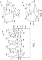
- FIGS. 2 and 3 first and second angled perspective views of an exemplary flow control device 102 are depicted, respectively, in accordance with an embodiment of the present invention. It should be noted that different shapes or constructions of the flow control device 102 are possible and contemplated, as are different heights and widths, and the flow control device 102 depicted in FIGS. 2 and 3 is merely one exemplary design configured to engage with a correspondingly designed blade and rotor assembly. In FIGS.
- the flow control device 102 includes a first side 130 having a first curved contour 132 which engages with at least a portion of a first side 110 of a rotor blade slot 106, and a second side 134 having a second curved contour 136 which engages with at least a portion of a second side 112 of a rotor blade slot 106. As shown in relation to FIG.
- the sides 130, 134 of the flow control device 102 may be designed, shaped, contoured, machined, and/or otherwise formed to mateably engage and/or mateably couple with at least a portion of the respective first and second sides 110, 112 of a respective rotor blade slot 106 so that there is a relatively tight connection between the flow control device 102 and the sides of 110, 112 of the slot 106 to prevent leakage of coolant around the flow control device 102.
- the flow control device 102 depicted in FIGS. 2 and 3 further includes a top surface 138 that is configured to mateably engage with a portion of a bottom surface 156 of a rotor blade 108, or even engage with a short indented portion of the bottom surface 156 of the rotor blade 108. Additionally, the flow control device 102 depicted in FIGS. 2 and 3 includes a front surface 140 with a coupling 142 having a hook portion 144.
- the hook portion 144 may be configured to engage and secure a rotor blade tab 170 or other portion of a rotor blade 108 (e.g., a portion of the rotor blade at a rotor dovetail adj acent an block) to help secure the flow control device 102 to the rotor blade 108.
- the flow control device 102 further includes an outer flat wall 146 with a strip portion 148 that can be configured to fill at least part of an exposed portion 155 between an extremity 128 of the corresponding rotor blade 108 and a top edge 126 of an outer wall 124 of the block 114 (or of a rotor 104 in a situation where the outer wall 124 and the block 114 are one integral part of the rotor 104), as discussed further below in relation to FIGS. 6A and 6B .
- a bottom surface 150 of the flow control device 102 which is generally opposite the top surface 138 of the flow control device 102, includes a flow modifier 152 (which in the embodiment shown in FIGS. 2 and 3 incorporates a curved contour), which is at least partially positioned in or oriented towards a junction 122 of a rotor blade 108 to help control a flow path for coolant traveling through the corresponding junction 122 when the flow control device 102 is coupled to the rotor blade 108.
- the flow modifier 152 may include one or multiple shapes, grooves, curves, and/or flow paths that direct a flow of coolant through the junction 122 to optimize flow dynamics.
- FIG. 4 a first partial, exploded, angled, perspective view of the blade and rotor assembly 100 of FIG. 1 is depicted, in accordance with an embodiment of the present invention.
- FIG. 4 depicts the rotor 104, the block 114, and an exemplary rotor blade 108 coupled to two adjacent rotor support blocks 118 (for clarity, this is presented in isolation; this may be repeated around the circumference of the rotor 104).
- the junction 122 in the block wall 114 includes an opening 154 oriented towards the bottom surface 156 of the rotor blade 108.
- an exposed portion 155 through which coolant may escape the junction 122.
- the junction 122 includes a first opening 158 that is an outlet for coolant supplied through a rotor supply channel 160 that extends radially through the rotor 104 from a center portion of the rotor 104, the first opening 158 located on a first side 162 of the junction 122.
- the junction 122 further includes a second opening 164 on a second side 163 of the junction 122 that is an inlet for a blade supply channel 161 (e.g., a broach slot) that carries coolant beneath the rotor blade 108.
- the rotor supply channel 160 and the blade supply channel 161 may be in fluid communication through the junction 122.
- the opening 154 and the exposed portion 155 of the junction 122 may allow coolant (e.g., TCLA) to escape from the junction 122 when the flow control device 102 is not in position and coupled to the extremity 128 of the rotor blade 108, at least partially sealing the opening 154 and the exposed portion 155 of the junction 122.
- coolant e.g., TCLA
- FIG. 6B depicts how the flow modifier 152 of the flow control device 102 may be positioned in and/or oriented towards the junction 122 to at least partially direct or channel a flow of coolant from the rotor supply channel 160 to the blade supply channel 161 through the junction 122.
- the flow control device 102 when the flow control device 102 is in place, and as coolant travels from the first opening 158 to the second opening 164 within the junction 122, the coolant is able to follow a more linear, unidirectional path through the junction 122.
- the flow modifier 152 is at least partially positioned between a first side wall 166 and a second side wall 168 of the junction 122 within the block 114, and may be oriented towards at least one of the first opening 158 and the second opening 164, and/or rather, towards at least one of the first and the second sides 162, 163.
- the shape, features, and/or curvature of the flow modifier 152 shown in FIG. 6B may be adjusted or varied to provide the most optimized flow dynamics through the junction 122, and also to minimize or reduce pressure loss and leakage of coolant in the junction 122.
- FIG. 5 a second partial, exploded, angled, perspective view of the blade and rotor assembly 100 shown in FIG. 1 , with adjacent rotor blades 108 and adjacent rotor support blocks 118 removed for clarity, is depicted, in accordance with an embodiment of the present invention.
- the rotor blade 108 is shown with a first mateable engaging side 111, a second mateable engaging side 113, and a rotor blade tab 170.
- the outer flat wall 146 of the flow control device 102 may, in embodiments, at least partially align with the outer wall 124 of the block 114 and/or of the rotor 104, and/or may align with a face 176 of the rotor blade 108, helping the flow control device 102 fill or cover the exposed portion 155 of the junction 122. Additionally, the flow control device 102 may be coupled to a front surface 175 of the rotor blade tab 170 when the hook portion 144 of the flow control device 102 is coupled to the rotor blade tab 170.
- the rotor supply channel 160 is oriented axially along an outside surface of the rotor 104, and more specifically, is at least partially defined by a bottom channel 172 running along an outer surface of the rotor 104 and a bottom side 174 of the corresponding rotor blade 108.
- the blade supply channel 161 may take any number of shapes, including a circular, ovular, trapezoidal, or elliptical shape, among other shapes, and may not be defined by a part of the rotor blade 108 as shown in FIG. 5 , but may be internal to the rotor 104 or simply separate from the rotor blade 108.
- the strip portion 148 may be in contact with the top edge 126 of the outer wall 124 to help seal the exposed portion 155 and prevent leakage of coolant around the flow control device 102 (this can be further facilitated by applying an abradable coating to the flow control device 102, junction 122, and/or rotor blade 108).
- FIG. 6A a partial, cross-sectional, angled, perspective view of the assembly 100 of FIG. 1 prior to installation of a flow control device 102 is provided, in accordance with an embodiment of the present invention.
- the block 114 is shown more clearly, within which the junction 122 is at least partially defined by the first side 162 having the first opening 158 that is an outlet for coolant from the rotor supply channel 160, and the second side 163 having a second opening 164 that is an inlet for the coolant that has exited having the first opening 158 that is an outlet for coolant from the rotor supply channel 160, and the second side 163 having a second opening 164 that is an inlet for the coolant that has exited the rotor supply channel 160 and entered the junction 122, allowing the coolant to travel down the rotor supply channel 161 beneath the rotor blade 108.
- the opening 154 of the junction 122 may allow at least a portion of the coolant to escape from the junction 122 out of the exposed portion 155 when the flow control device 102 is not in place in the assembly 100. Additionally, when the coolant enters the unsealed junction 122 from the rotor supply channel 160, the sudden expansion of the coolant causes a pressure loss that reduces efficiency of the flow supply system. Thus, providing a flow control device 102 that seals the exposed portion 155 of the junction 122, and that includes the flow modifier 152 that directs the flow of coolant traveling within the junction 122, may improve flow dynamics and pressure loss.
- FIG. 6B a partial, cross-sectional, angled, perspective view of the blade and rotor assembly depicted in FIG. 6A after installation of a flow control device is provided, in accordance with an embodiment of the present invention.
- the flow control device 102 is positioned at least partially between the extremity 128 of the rotor blade 108 and the junction 122.
- the strip portion 148 is in contact with the top edge 126 of the outer wall 124 to help seal the exposed portion 155.
- the top surface 138 of the flow control device 102 is coupled to the bottom surface 156 of the rotor blade 108.
- FIG. 6B demonstrates how the installed flow control device 102 and the sealing of the junction 122 with the strip portion 148 prevents leakage of coolant through the opening 154 and the exposed portion 155 of the junction 122 shown in FIG. 6A .
- the flow modifier 152 of the flow control device 102 which in FIG. 6B is positioned substantially in the junction 122, helps to direct, or channel, the flow of coolant exiting from the rotor supply channel 160 towards the blade supply channel 161 to provide a more streamlined, laminar, and non-turbulent transition between the rotor supply channel 160 and the blade supply channel 161.
- the flow modifier 152 is oriented towards the junction 122, and extends at least partially between side walls 166, 168 of the junction 122 (side wall 168 is not visible due to the cut-away; see FIG.
- the flow control device 102 and more specifically, the flow modifier 152, also helps to meter the flow of coolant entering the blade supply channel 161 through the second opening 164 by controlling a cross-sectional area of the second opening 164, thereby controlling the entry of coolant into the second opening 164 and down the blade supply channel 161.
- the flow control device 102 provides a barrier between the junction 122 and the outside of the assembly 100, providing a more sealed pathway for coolant within the flow supply system. Additionally, as shown in FIG. 6B , the flow control device 102 is coupled to the rotor blade 108 independently of other rotor blades 108. In other words, the flow control device 102, although selectively coupled to one extremity 128 of the rotor blade 108, may not be secured or interlinked to other rotor blades 108, or components of the assembly 100 attached to other rotor blades 108, such that removing or installing the flow control device 102 in FIG.
- FIG. 6B requires decoupling of other parts of the assembly 100 or de-stacking of rotor blades 108 adjacent to the flow control device 102 shown in FIG. 6B .
- a single rotor blade 108 may be modified to attach or detach a flow control device 102 as needed, without de-stacking of multiple rotor blades 108.
- a level of coolant flow to the rotor blade channel 161 may be adjusted by varying the minimum cross-sectional area at the exit of the flow modifier 152 of each flow control device 102, or rather, adjusting the cross-sectional area where the coolant passes into the blade supply channel 161. This may be achieved by selecting a specific thickness of the flow control device 102 or a specific angle or design of the flow modifier 152, or by controlling an orifice or opening attached to the flow control device 102. As a result, an optimized aerodynamic configuration is provided for the coolant flow turn, and turbulence of coolant entering the blade supply channel 161 may be reduced or limited with the flow control device 102.
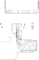
- FIG. 7 a relative total pressure distribution diagram associated with an exemplary flow supply system incorporating a flow control device is provided, in accordance with an embodiment of the present invention.
- a flow control device On the right side of FIG. 7 is a dimensionless scale for the relative total pressure chart 702.
- a flow control device which may be the flow control device 102 with the flow modifier 152 shown in FIGS.
- the flow control device helps to smooth out the flow and provide a less turbulent transition between the first channel and the second channel, as depicted in FIG. 7 .
- a block diagram of a method 800 of adjusting a cooling flow path in a rotating flow supply system is provided, in accordance with an embodiment of the present invention.
- a blade and rotor assembly such as the rotor assembly 100 shown in FIG. 1 .
- the assembly comprises a rotor, such as the rotor 104 shown in FIG. 1 , having a rotor blade slot, such as the slot 106 shown in FIG. 1 , a rotor blade, such as the rotor blade 108 shown in FIG. 1 , a first channel, such as the rotor supply channel 160 shown in FIGS.
- the assembly further comprises a second channel, such as the blade supply channel 161 shown in FIGS. 6A and 6B , extending from a second opening, such as the second opening 164 shown in FIGS. 6A and 6B , at the junction axially along the rotor under the rotor blade when the rotor blade is positioned in the rotor blade slot, where the junction includes an exposed portion, such as the exposed portion 155 shown in FIG.
- a flow control device such as the flow control device 102 shown in FIGS. 2 and 3 , is removably coupled to an extremity of the rotor blade, such as the extremity 128 shown in FIGS. 6A and 6B , where the flow control device includes a flow modifier, such as the flow modifier 152 shown in FIGS. 2 and 3 , oriented towards at least one of the first opening and the second opening, and where the flow control device and the extremity of the rotor blade are de-coupleable independently of other rotor blades and respective flow control devices coupled to the rotor.
- a flow control device such as the flow control device 102 shown in FIGS. 2 and 3
- FIG. 9 is an angled, perspective view of a first alternate flow control device 102, not in accordance with the present invention.
- the flow control device 102 includes a flow modifier 152, which in the embodiment shown in FIG. 9 is in the form of a chamfer 178 on the bottom 150, that may provide a directional bias for a flow of coolant passing along the bottom 150 of the flow control device 102 when the flow control device 102 is positioned in a junction, such as the junction 122 shown in FIGS. 6A and 6B .
- FIG. 10 is an angled, perspective view of a second alternate flow control device 102, not in accordance with the present invention.
- the flow control device 102 includes a flow modifier 152, which in the embodiment shown in FIG. 10 is in the form of a flow tab 180 on the bottom 150, that may help to channel, or direct, a flow of coolant passing along the bottom 150 of the flow control device 102.
- the flow tab 180 includes an opening 182 that may meter, direct, and/or otherwise control the flow of coolant traveling along the bottom 150 of the flow control device 102 and through the opening 182, depending on the shape, size, and orientation of the opening 182 in the flow tab 180.
- An exemplary flow control device, or seal block, for improving flow dynamics, pressure loss, and leakage of coolant, among other issues, in a rotating flow supply system may include a first end having a flat portion and a coupling portion.
- the coupling portion may include a hook for engaging a bucket tab on an extremity of a rotor blade, or another portion of the extremity of a rotor blade.
- the flow control device may include a second end that is substantially flat, and that may be parallel to at least a portion of the first end.
- the flow control device may further include a first side that is configured to mateably engage with at least a portion of a side of a first blade support block, and a second side configured to mateably engage with at least a portion of a side of a second blade support block.
- the flow control device may include a top surface that is at least partially flat, and that is configured to at least partially engage with a bottom surface of an extremity of a rotor blade.
- the flow control device may further include a bottom surface with a flow modifier.
- the flow modifier may form, utilize, and/or include a curved contour, a chamfer, and/or a flow tab with an orifice, among other configurations, to help direct a flow of coolant. Additionally, any of these structures may also compliment a strip portion on the bottom of the flow control device which may be configured to help seal an exposed portion of a corresponding junction in which the flow control device is positioned.
- the flow control device may further be described as a removable flow metering block, or seal block, that may be positioned at an exit of a flow supply system, or a constant flow supply system, and may be designed to fit into a rotor dovetail adjacent a rotor block, such as the block 114 described in this disclosure.
- the flow control device may engage a rotor dovetail by being installed through a rotor blade slot, during which the flow control device is held in place with a blade hook slot on the rotor blade.
- the flow control device may reduce the flow delivering capacity of the constant flow supply system, acting as an external component to the system, to provide a decrease in pressure loss and overall leakage flow around the flow control device.
- the possible retro-fitted nature of the flow control device due to its ability to be custom designed and fitted at an exit of a flow supply system, means that modification to an existing blade and rotor assembly may not be required at an installation site. In this respect, modification of other parts of the assembly that would require removing, re-machining, or replacing those parts may also not be required.
- each flow control device may be coupled to the rotor independently of other flow control devices and their respective rotor blades. More specifically, each flow control device may be independently coupled to the extremity of a corresponding rotor blade and also may be de-coupled from the extremity of the corresponding rotor blade without de-stacking, dislodging, or removing adjacent or additional rotor blades around the rotor, or removing pieces that connect adjacent rotor blades, junctions, or flow control devices. In other words, the flow control device may not be selectively secured to more than one rotor blade.
- the flow control device allows improved sealing capability of flow leaking through the exposed portion, which may be across from the blade supply channel (which in turbine blade and rotor assemblies is often referred to as a "broach slot").
- the curved shape or contour on the bottom side of the flow control device helps to prevent air from flowing in an opposite direction as intended, or rather, away from the blade supply channel.
- the flow control device may provide a greater cross-sectional area of sealing surface around the exposed portion and junction.
- the flow control device and/or rotor blade slot may further include an abradable coating that may help to provide a sealed connection around the flow control device.
- the abradable coating may be applied to portions of the flow control device which are in contact with other portions of the blade and rotor assembly, such as the bottom surface 150 and the strip portion 148 of the flow control device 102 shown in FIGS. 2 and 3 that may provide a sealing barrier between the flow control device 102 and the top edge 126 of the outer wall 124.
- the portion 148 of the flow control device 102 shown in FIGS. 2 and 3 that may provide a sealing barrier between the flow control device 102 and the top edge 126 of the outer wall 124.
- the abradable coating may also be applied to sides of the flow control device, such as the sides 130, 134 of the flow control device 102 shown in FIGS. 2 and 3 , and/or a coupling or hook portion of the flow control device, such as the coupling 142 and/or the hook portion 144 of the flow control device 102 shown in FIGS. 2 and 3 . Additional surfaces on or around the flow control device (e.g., on an extremity of the rotor blade) may have applied an abradable coating as needed to help seal the flow control device in the corresponding junction and help prevent pressure loss.
Landscapes
- Engineering & Computer Science (AREA)
- Mechanical Engineering (AREA)
- General Engineering & Computer Science (AREA)
- Turbine Rotor Nozzle Sealing (AREA)
Description
- The invention relates to a flow control device for a rotating flow supply system, such as a rotating constant flow supply system used in a rotor and blade assembly in a gas turbine.
- Gas turbines include numerous components, such as, for example, a combustor for mixing air and fuel for ignition, a turbine blade and rotor assembly for producing power, and a flow supply system for supplying cooling fluid/gas ("coolant") to turbine blade and rotor components when the gas turbine is in operation. Gas turbine combustors often operate at temperatures that can exceed 1371,1 °C (2,500 degrees Fahrenheit), and as such, the turbine components, including the blade and rotor components, are exposed to these high temperatures. As a result, the flow supply system is useful for cooling the blade and rotor components during operation of the gas turbine to help maintain durability requirements of these components.
- Turbine cooling and leakage air ("TCLA") is one form of coolant which may be supplied in a pressurized form through the flow supply system for cooling the blade and rotor components. However, when TCLA, or other coolants, escape from the flow supply system, this negatively impacts the durability of the blade and rotor components, as well as the efficiency and performance of the gas turbine.
- In certain blade and rotor assemblies, the flow supply system includes a plurality of junctions at respective rotor blade connections (e.g., a rotor dovetail adjacent a rotor block) through which coolant channels are in fluid communication to supply coolant to the associated blade and rotor components. Examples of blades and rotor assemblies of this kind are disclosed in documents
US2012/183389 ,US 4505640 ,JP2001012205 EP2312124 . The junction often includes an exposed portion that contributes to the discussed pressure loss, leakage, and sub-optimal flow dynamics of the coolant in the flow supply system, and thus contributes to inefficiency of the gas turbine. However, modifying the rotor and/or the blades to correct this deficiency can be expensive and require complex de-stacking of the rotor blades. Modification also does not allow for continued use of existing, unmodified blade and rotor components. As a result, a new and versatile flow control device that solves these challenges, among others, is needed. - This summary is intended to provide a high-level overview of various aspects of the invention and to introduce a selection of concepts that are further described below in the detailed description section. This summary is not intended to identify key or essential features of the claimed subject matter, nor is it intended to be used as an aid in isolation to determine the scope of the claimed subject matter. The scope of the invention is defined by the claims.
- In brief, and at a high level, this disclosure describes, among other things, a flow control device that may be used with a rotating flow supply system in a gas turbine. The flow control device may be coupled to a blade and rotor assembly to modify the flow dynamics of a coolant, such as compressed air, traveling through the rotating flow supply system for cooling the blade and rotor components. The device may direct, control, meter, channel, and/or otherwise modify the flow of the coolant to improve flow dynamics, and additionally may reduce overall pressure loss and leakage of the coolant in the rotating flow supply system. The flow control device may further include a flow modifier (e.g., a curved contour, a chamfer, a flow tab with an opening, etc.) to help control or direct the flow of coolant traveling through the flow supply system.
- In a first embodiment of the invention, an assembly for controlling cooling flow in a flow supply system is provided as claimed in claim 1.
- In a second embodiment of the invention, a system for controlling cooling flow in gas turbines is provided as claimed in claim 7.
- In a third embodiment of the invention, a method of adjusting a cooling flow path in a rotating flow supply system is provided as claimed in claim 9.
- The flow control device described in this disclosure is discussed frequently in the context of rotating flow supply systems and gas turbine assemblies, but it is not limited only to such systems and assemblies. Rather, the flow control device described in this disclosure is applicable to any flow supply system, including a rotating or non-rotating flow supply system, pressurized or non-pressurized system, or gas, liquid fuel, or mixed fuel system or turbine, among others. Coolant used in the flow supply system, which may be a fluid or a gas, is also described in this disclosure to be non-limiting. The flow control device described herein may be referred to alternatively as a "seal block."
- The present invention is described in detail herein with reference to the attached figures, which are incorporated herein by reference, wherein:
-
FIG. 1 is a fragmentary elevation view of a portion of a gas turbine blade and rotor assembly that includes multiple flow control devices installed in the assembly, in accordance with an embodiment of the present invention; -
FIG. 2 is a first angled, perspective view of an exemplary flow control device, in accordance with an embodiment of the present invention; -
FIG. 3 is a second angled, perspective view of the flow control device depicted inFIG. 2 , in accordance with an embodiment of the present invention; -
FIG. 4 is a first partial, exploded, angled, perspective view of the blade and rotor assembly depicted inFIG. 1 , in accordance with an embodiment of the present invention; -
FIG. 5 is a second partial, exploded, angled, perspective view of the blade and rotor assembly depicted inFIG. 1 , in accordance with an embodiment of the present invention; -
FIG. 6A is a partial, cross-sectional, angled, perspective view of the rotor assembly ofFIG. 1 prior to installation of a flow control device, in accordance with an embodiment of the present invention; -
FIG. 6B is a partial, cross-sectional, angled, perspective view of the blade and rotor assembly depicted inFIG. 6A after installation of the flow control device, in accordance with an embodiment of the present invention; -
FIG. 7 is a relative total pressure distribution diagram associated with an exemplary flow supply system incorporating a flow control device, in accordance with an embodiment of the present invention; -
FIG. 8 is a block diagram of an exemplary method for controlling cooling flow in a rotating flow supply system, in accordance with an embodiment of the present invention; -
FIG. 9 is an angled, perspective view of a first alternate flow control device, not in accordance with the present invention; and -
FIG. 10 is an angled, perspective view of a second alternate flow control device, not in accordance with the present invention. - The subject matter of various aspects of the present invention is described with specificity herein to meet statutory requirements. However, the description itself is not intended to limit the scope of the invention. Rather, the claimed subject matter might be embodied or carried out in other ways to include different elements, combinations, components, or steps, including those similar to the ones described in this document, in conjunction with other present or future technologies. Furthermore, the term "step" as used in this disclosure shall not indicate any particular order of steps unless such an order is explicitly stated or required.
- At a high level, the present invention generally relates to a flow control device that may be used with a blade and rotor assembly in a gas turbine to control, direct, and/or meter coolant traveling through a rotating flow supply system in the blade and rotor assembly. More specifically, the flow control device may be coupled to an extremity (e.g., end portion) of a rotor blade, and/or may include a flow modifier oriented towards a junction in the flow supply system through which coolant supply channels connect, in order to direct, control, meter, and/or modify coolant flow through the junction and improve flow dynamics of the flow supply system. The flow modifier may utilize, for example, a curved contour, chamfer, or a flow tab with an orifice, or some other shape or external feature, to assist in directing, channeling, metering, or modifying the flow of coolant through the flow supply system. The flow control device may be configured to be coupled to and decoupled from the blade and rotor assembly and/or the junction without de-stacking adjacent rotor blades. The flow control device may also act as a seal block, or rather, be configured to fill, seal, or cover at least a portion of an exposed portion of the junction to reduce leakage and associated pressure loss at the junction.
- Having described some general aspects of the invention, reference is now made to
FIG. 1 , which depicts a fragmentary elevation view of a portion of a gas turbine blade androtor assembly 100 that includes multipleflow control devices 102 installed in theassembly 100, in accordance with an embodiment of the present invention.FIG. 1 depicts arotor 104 having a plurality ofrotor blade slots 106 defined at least partially by a plurality ofrotor support blocks 118 which are configured to receive and secure a plurality ofrespective rotor blades 108. Eachrotor blade slot 106 includes afirst side 110 and asecond side 112 that engage with a respectivefirst side 111 andsecond side 113 of arespective rotor blade 108 positioned in therotor blade slot 106. Additionally, therotor 104 may include anblock 114 that extends circumferentially around anedge 116 of therotor 104. Theblock 114 may engage with therotor 104 and/or arotor support block 118 and be held in place with tapered bolts, or another securing component. - As shown in
FIGS. 1 and4 , sections of theblock 114 include different structural characteristics. For example, sections of theblock 114 that are beneath the respectiverotor support blocks 118 may be solid, and sections of theblock 114 that are beneathrespective rotor blades 108 may include a hollow cavity (shown with dotted lines inFIG. 1 ), or rather, junctions 122 (the details of eachjunction 122 inFIG. 1 are obscured by anouter wall 124 of theblock 114; seeFIGS. 4 ,6A, and 6B for further detail). Thesides rotor blades 108 and thesides rotor blade slots 106 each include firtree-type, curved contours that allow therotor support blocks 118 to engage and secure therotor blades 108, which prevents radial movement of therotor blades 108 when theassembly 100 is in operation, and spinning. -
FIG. 1 further depicts the plurality offlow control devices 102 positioned between therespective rotor blades 108 and therotor 104. In this respect, the positioning of theflow control devices 102 prevents leakage of coolant that is traveling through the junctions 122 (e.g., between coolant supply channels that connect within the junctions 122) to cool theblades 108 and therotor 104. Eachflow control device 102 depicted inFIG. 1 is removably coupled to eachrespective rotor blade 108, such that the coupling can be manipulated independently ofadjacent rotor blades 108 so that aflow control device 102 can be installed or removed without de-stacking therotor 104 or theblock 114. Theflow control devices 102 inFIG. 1 may also be coupled to atop edge 126 of theouter wall 124 of theblock 114 and anextremity 128 of therespective rotor blade 108 in theassembly 100, to help seal thejunction 122 and prevent leakage of coolant passing through thejunction 122. - Referring now to
FIGS. 2 and 3 , first and second angled perspective views of an exemplaryflow control device 102 are depicted, respectively, in accordance with an embodiment of the present invention. It should be noted that different shapes or constructions of theflow control device 102 are possible and contemplated, as are different heights and widths, and theflow control device 102 depicted inFIGS. 2 and 3 is merely one exemplary design configured to engage with a correspondingly designed blade and rotor assembly. InFIGS. 2 and 3 , theflow control device 102 includes afirst side 130 having a firstcurved contour 132 which engages with at least a portion of afirst side 110 of arotor blade slot 106, and asecond side 134 having a secondcurved contour 136 which engages with at least a portion of asecond side 112 of arotor blade slot 106. As shown in relation toFIG. 1 , thesides flow control device 102 may be designed, shaped, contoured, machined, and/or otherwise formed to mateably engage and/or mateably couple with at least a portion of the respective first andsecond sides rotor blade slot 106 so that there is a relatively tight connection between theflow control device 102 and the sides of 110, 112 of theslot 106 to prevent leakage of coolant around theflow control device 102. - The
flow control device 102 depicted inFIGS. 2 and 3 further includes atop surface 138 that is configured to mateably engage with a portion of abottom surface 156 of arotor blade 108, or even engage with a short indented portion of thebottom surface 156 of therotor blade 108. Additionally, theflow control device 102 depicted inFIGS. 2 and 3 includes afront surface 140 with acoupling 142 having ahook portion 144. Thehook portion 144 may be configured to engage and secure arotor blade tab 170 or other portion of a rotor blade 108 (e.g., a portion of the rotor blade at a rotor dovetail adj acent an block) to help secure theflow control device 102 to therotor blade 108. Theflow control device 102 further includes an outerflat wall 146 with astrip portion 148 that can be configured to fill at least part of an exposedportion 155 between anextremity 128 of thecorresponding rotor blade 108 and atop edge 126 of anouter wall 124 of the block 114 (or of arotor 104 in a situation where theouter wall 124 and theblock 114 are one integral part of the rotor 104), as discussed further below in relation toFIGS. 6A and 6B . - As shown in
FIGS. 2 and 3 , abottom surface 150 of theflow control device 102, which is generally opposite thetop surface 138 of theflow control device 102, includes a flow modifier 152 (which in the embodiment shown inFIGS. 2 and 3 incorporates a curved contour), which is at least partially positioned in or oriented towards ajunction 122 of arotor blade 108 to help control a flow path for coolant traveling through the correspondingjunction 122 when theflow control device 102 is coupled to therotor blade 108. Theflow modifier 152 may include one or multiple shapes, grooves, curves, and/or flow paths that direct a flow of coolant through thejunction 122 to optimize flow dynamics. - Referring now to
FIG. 4 , a first partial, exploded, angled, perspective view of the blade androtor assembly 100 ofFIG. 1 is depicted, in accordance with an embodiment of the present invention.FIG. 4 depicts therotor 104, theblock 114, and anexemplary rotor blade 108 coupled to two adjacent rotor support blocks 118 (for clarity, this is presented in isolation; this may be repeated around the circumference of the rotor 104). Additionally, thejunction 122 in theblock wall 114 includes anopening 154 oriented towards thebottom surface 156 of therotor blade 108. Furthermore, between atop edge 126 of theouter wall 124 of theblock 114 and theextremity 128 of therotor blade 108 is an exposedportion 155 through which coolant may escape thejunction 122. - The
junction 122 includes afirst opening 158 that is an outlet for coolant supplied through arotor supply channel 160 that extends radially through therotor 104 from a center portion of therotor 104, thefirst opening 158 located on afirst side 162 of thejunction 122. Thejunction 122 further includes asecond opening 164 on asecond side 163 of thejunction 122 that is an inlet for a blade supply channel 161 (e.g., a broach slot) that carries coolant beneath therotor blade 108. In this respect, therotor supply channel 160 and theblade supply channel 161 may be in fluid communication through thejunction 122. The coolant exits therotor supply channel 160 at thefirst opening 158, and at least a portion of the coolant that is ejected into thejunction 122, and which does not escape thejunction 122 through theopening 154 and the exposedportion 155, travels into theblade supply channel 161. As shown inFIGS. 6A & 6B , theopening 154 and the exposedportion 155 of thejunction 122 may allow coolant (e.g., TCLA) to escape from thejunction 122 when theflow control device 102 is not in position and coupled to theextremity 128 of therotor blade 108, at least partially sealing theopening 154 and the exposedportion 155 of thejunction 122. - Furthermore,
FIG. 6B depicts how theflow modifier 152 of theflow control device 102 may be positioned in and/or oriented towards thejunction 122 to at least partially direct or channel a flow of coolant from therotor supply channel 160 to theblade supply channel 161 through thejunction 122. Stated differently, when theflow control device 102 is in place, and as coolant travels from thefirst opening 158 to thesecond opening 164 within thejunction 122, the coolant is able to follow a more linear, unidirectional path through thejunction 122. Theflow modifier 152 is at least partially positioned between afirst side wall 166 and asecond side wall 168 of thejunction 122 within theblock 114, and may be oriented towards at least one of thefirst opening 158 and thesecond opening 164, and/or rather, towards at least one of the first and thesecond sides flow modifier 152 shown inFIG. 6B may be adjusted or varied to provide the most optimized flow dynamics through thejunction 122, and also to minimize or reduce pressure loss and leakage of coolant in thejunction 122. - Referring now to
FIG. 5 , a second partial, exploded, angled, perspective view of the blade androtor assembly 100 shown inFIG. 1 , withadjacent rotor blades 108 and adjacent rotor support blocks 118 removed for clarity, is depicted, in accordance with an embodiment of the present invention. InFIG. 5 , therotor blade 108 is shown with a firstmateable engaging side 111, a secondmateable engaging side 113, and arotor blade tab 170. Theflow control device 102 depicted inFIG. 5 includes thecoupling 142 and thehook portion 144, with thehook portion 144 configured to engage and secure therotor blade tab 170 to couple theflow control device 102 to theextremity 128 of therotor blade 108. Furthermore, the outerflat wall 146 of theflow control device 102 may, in embodiments, at least partially align with theouter wall 124 of theblock 114 and/or of therotor 104, and/or may align with aface 176 of therotor blade 108, helping theflow control device 102 fill or cover the exposedportion 155 of thejunction 122. Additionally, theflow control device 102 may be coupled to afront surface 175 of therotor blade tab 170 when thehook portion 144 of theflow control device 102 is coupled to therotor blade tab 170. - In the exemplary embodiment shown in
FIG. 5 , therotor supply channel 160 is oriented axially along an outside surface of therotor 104, and more specifically, is at least partially defined by abottom channel 172 running along an outer surface of therotor 104 and abottom side 174 of thecorresponding rotor blade 108. Theblade supply channel 161 may take any number of shapes, including a circular, ovular, trapezoidal, or elliptical shape, among other shapes, and may not be defined by a part of therotor blade 108 as shown inFIG. 5 , but may be internal to therotor 104 or simply separate from therotor blade 108. Thestrip portion 148 may be in contact with thetop edge 126 of theouter wall 124 to help seal the exposedportion 155 and prevent leakage of coolant around the flow control device 102 (this can be further facilitated by applying an abradable coating to theflow control device 102,junction 122, and/or rotor blade 108). - Referring now to
FIG. 6A , a partial, cross-sectional, angled, perspective view of theassembly 100 ofFIG. 1 prior to installation of aflow control device 102 is provided, in accordance with an embodiment of the present invention. InFIG. 6A , theblock 114 is shown more clearly, within which thejunction 122 is at least partially defined by thefirst side 162 having thefirst opening 158 that is an outlet for coolant from therotor supply channel 160, and thesecond side 163 having asecond opening 164 that is an inlet for the coolant that has exited having thefirst opening 158 that is an outlet for coolant from therotor supply channel 160, and thesecond side 163 having asecond opening 164 that is an inlet for the coolant that has exited therotor supply channel 160 and entered thejunction 122, allowing the coolant to travel down therotor supply channel 161 beneath therotor blade 108. Theopening 154 of thejunction 122 may allow at least a portion of the coolant to escape from thejunction 122 out of the exposedportion 155 when theflow control device 102 is not in place in theassembly 100. Additionally, when the coolant enters the unsealedjunction 122 from therotor supply channel 160, the sudden expansion of the coolant causes a pressure loss that reduces efficiency of the flow supply system. Thus, providing aflow control device 102 that seals the exposedportion 155 of thejunction 122, and that includes theflow modifier 152 that directs the flow of coolant traveling within thejunction 122, may improve flow dynamics and pressure loss. - Referring now to
FIG. 6B , a partial, cross-sectional, angled, perspective view of the blade and rotor assembly depicted inFIG. 6A after installation of a flow control device is provided, in accordance with an embodiment of the present invention. InFIG. 6B , theflow control device 102 is positioned at least partially between theextremity 128 of therotor blade 108 and thejunction 122. Thestrip portion 148 is in contact with thetop edge 126 of theouter wall 124 to help seal the exposedportion 155. Thetop surface 138 of theflow control device 102 is coupled to thebottom surface 156 of therotor blade 108. Further, therotor blade tab 170, or rather, ahook slot 171 associated with therotor blade tab 170, of therotor blade 108 is engaged with thehook portion 144 on theflow control device 102.FIG. 6B demonstrates how the installedflow control device 102 and the sealing of thejunction 122 with thestrip portion 148 prevents leakage of coolant through theopening 154 and the exposedportion 155 of thejunction 122 shown inFIG. 6A . - Additionally, as shown in
FIG. 6B , theflow modifier 152 of theflow control device 102, which inFIG. 6B is positioned substantially in thejunction 122, helps to direct, or channel, the flow of coolant exiting from therotor supply channel 160 towards theblade supply channel 161 to provide a more streamlined, laminar, and non-turbulent transition between therotor supply channel 160 and theblade supply channel 161. Theflow modifier 152 is oriented towards thejunction 122, and extends at least partially betweenside walls side wall 168 is not visible due to the cut-away; seeFIG. 4 ), and faces towards at least one of the first and thesecond openings second sides junction 122. Theflow control device 102, and more specifically, theflow modifier 152, also helps to meter the flow of coolant entering theblade supply channel 161 through thesecond opening 164 by controlling a cross-sectional area of thesecond opening 164, thereby controlling the entry of coolant into thesecond opening 164 and down theblade supply channel 161. - As shown in
FIG. 6B , theflow control device 102 provides a barrier between thejunction 122 and the outside of theassembly 100, providing a more sealed pathway for coolant within the flow supply system. Additionally, as shown inFIG. 6B , theflow control device 102 is coupled to therotor blade 108 independently ofother rotor blades 108. In other words, theflow control device 102, although selectively coupled to oneextremity 128 of therotor blade 108, may not be secured or interlinked toother rotor blades 108, or components of theassembly 100 attached toother rotor blades 108, such that removing or installing theflow control device 102 inFIG. 6B requires decoupling of other parts of theassembly 100 or de-stacking ofrotor blades 108 adjacent to theflow control device 102 shown inFIG. 6B . In this respect, asingle rotor blade 108 may be modified to attach or detach aflow control device 102 as needed, without de-stacking ofmultiple rotor blades 108. - Furthermore, a level of coolant flow to the
rotor blade channel 161 may be adjusted by varying the minimum cross-sectional area at the exit of theflow modifier 152 of eachflow control device 102, or rather, adjusting the cross-sectional area where the coolant passes into theblade supply channel 161. This may be achieved by selecting a specific thickness of theflow control device 102 or a specific angle or design of theflow modifier 152, or by controlling an orifice or opening attached to theflow control device 102. As a result, an optimized aerodynamic configuration is provided for the coolant flow turn, and turbulence of coolant entering theblade supply channel 161 may be reduced or limited with theflow control device 102. - Referring now to
FIG. 7 , a relative total pressure distribution diagram associated with an exemplary flow supply system incorporating a flow control device is provided, in accordance with an embodiment of the present invention. On the right side ofFIG. 7 is a dimensionless scale for the relative total pressure chart 702. On the left ofFIG. 7 is an exemplary pressure diagram 704 for a junction, such as thejunction 122 inFIG. 4 , in a flow supply system used in a blade and rotor assembly, such as theassembly 100 that includes theflow control device 102. As shown by the pressure indications inFIG. 7 , a flow control device, which may be theflow control device 102 with theflow modifier 152 shown inFIGS. 2-3 , helps to direct the flow of coolant from a first direction in the junction to a second direction in the junction, or possibly rather, from a first coolant supply channel to a second coolant supply channel, which may be therotor supply channel 160 and theblade supply channel 161 shown inFIGS. 6A and 6B , respectively. The flow control device, and in particular, the flow modifier, helps to smooth out the flow and provide a less turbulent transition between the first channel and the second channel, as depicted inFIG. 7 . - Referring now to
FIG. 8 , a block diagram of amethod 800 of adjusting a cooling flow path in a rotating flow supply system is provided, in accordance with an embodiment of the present invention. At ablock 810, a blade and rotor assembly, such as therotor assembly 100 shown inFIG. 1 , is provided. The assembly comprises a rotor, such as therotor 104 shown inFIG. 1 , having a rotor blade slot, such as theslot 106 shown inFIG. 1 , a rotor blade, such as therotor blade 108 shown inFIG. 1 , a first channel, such as therotor supply channel 160 shown inFIGS. 6A and 6B , extending radially outward in the rotor to a first opening, such as thefirst opening 158 shown inFIGS. 6A and 6B , at a junction, such as thejunction 122 shown inFIGS. 6A and 6B , adjacent the rotor blade slot. The assembly further comprises a second channel, such as theblade supply channel 161 shown inFIGS. 6A and 6B , extending from a second opening, such as thesecond opening 164 shown inFIGS. 6A and 6B , at the junction axially along the rotor under the rotor blade when the rotor blade is positioned in the rotor blade slot, where the junction includes an exposed portion, such as the exposedportion 155 shown inFIG. 6A , and where the first and second channels are in fluid communication through the junction. At asecond step 812, a flow control device, such as theflow control device 102 shown inFIGS. 2 and 3 , is removably coupled to an extremity of the rotor blade, such as theextremity 128 shown inFIGS. 6A and 6B , where the flow control device includes a flow modifier, such as theflow modifier 152 shown inFIGS. 2 and 3 , oriented towards at least one of the first opening and the second opening, and where the flow control device and the extremity of the rotor blade are de-coupleable independently of other rotor blades and respective flow control devices coupled to the rotor. -
FIG. 9 is an angled, perspective view of a first alternateflow control device 102, not in accordance with the present invention. InFIG. 9 , theflow control device 102 includes aflow modifier 152, which in the embodiment shown inFIG. 9 is in the form of achamfer 178 on the bottom 150, that may provide a directional bias for a flow of coolant passing along thebottom 150 of theflow control device 102 when theflow control device 102 is positioned in a junction, such as thejunction 122 shown inFIGS. 6A and 6B . -
FIG. 10 is an angled, perspective view of a second alternateflow control device 102, not in accordance with the present invention. InFIG. 10 , theflow control device 102 includes aflow modifier 152, which in the embodiment shown inFIG. 10 is in the form of aflow tab 180 on the bottom 150, that may help to channel, or direct, a flow of coolant passing along thebottom 150 of theflow control device 102. Theflow tab 180 includes anopening 182 that may meter, direct, and/or otherwise control the flow of coolant traveling along thebottom 150 of theflow control device 102 and through theopening 182, depending on the shape, size, and orientation of theopening 182 in theflow tab 180. - An exemplary flow control device, or seal block, for improving flow dynamics, pressure loss, and leakage of coolant, among other issues, in a rotating flow supply system may include a first end having a flat portion and a coupling portion. The coupling portion may include a hook for engaging a bucket tab on an extremity of a rotor blade, or another portion of the extremity of a rotor blade. The flow control device may include a second end that is substantially flat, and that may be parallel to at least a portion of the first end. The flow control device may further include a first side that is configured to mateably engage with at least a portion of a side of a first blade support block, and a second side configured to mateably engage with at least a portion of a side of a second blade support block. The flow control device may include a top surface that is at least partially flat, and that is configured to at least partially engage with a bottom surface of an extremity of a rotor blade. The flow control device may further include a bottom surface with a flow modifier. The flow modifier may form, utilize, and/or include a curved contour, a chamfer, and/or a flow tab with an orifice, among other configurations, to help direct a flow of coolant. Additionally, any of these structures may also compliment a strip portion on the bottom of the flow control device which may be configured to help seal an exposed portion of a corresponding junction in which the flow control device is positioned.
- The flow control device may further be described as a removable flow metering block, or seal block, that may be positioned at an exit of a flow supply system, or a constant flow supply system, and may be designed to fit into a rotor dovetail adjacent a rotor block, such as the
block 114 described in this disclosure. The flow control device may engage a rotor dovetail by being installed through a rotor blade slot, during which the flow control device is held in place with a blade hook slot on the rotor blade. The flow control device may reduce the flow delivering capacity of the constant flow supply system, acting as an external component to the system, to provide a decrease in pressure loss and overall leakage flow around the flow control device. The possible retro-fitted nature of the flow control device, due to its ability to be custom designed and fitted at an exit of a flow supply system, means that modification to an existing blade and rotor assembly may not be required at an installation site. In this respect, modification of other parts of the assembly that would require removing, re-machining, or replacing those parts may also not be required. - For each rotor blade positioned radially around the rotor, the corresponding flow control device may be coupled to the rotor independently of other flow control devices and their respective rotor blades. More specifically, each flow control device may be independently coupled to the extremity of a corresponding rotor blade and also may be de-coupled from the extremity of the corresponding rotor blade without de-stacking, dislodging, or removing adjacent or additional rotor blades around the rotor, or removing pieces that connect adjacent rotor blades, junctions, or flow control devices. In other words, the flow control device may not be selectively secured to more than one rotor blade. By having this segmented, separated attachment construction, modification of the blade and rotor assembly is possible without the additional work of moving or de-coupling rotor blades or pieces that interlink multiple rotor blades, or disassembling the block. This also allows different or independently designed flow control devices to be used with multiple rows of turbine blades at the same time with different levels of individual performance for the different rows of turbine blades, in order to provide maximum versatility for blade and rotor cooling.
- The flow control device allows improved sealing capability of flow leaking through the exposed portion, which may be across from the blade supply channel (which in turbine blade and rotor assemblies is often referred to as a "broach slot"). The curved shape or contour on the bottom side of the flow control device helps to prevent air from flowing in an opposite direction as intended, or rather, away from the blade supply channel. The flow control device may provide a greater cross-sectional area of sealing surface around the exposed portion and junction.
- The flow control device and/or rotor blade slot may further include an abradable coating that may help to provide a sealed connection around the flow control device. The abradable coating may be applied to portions of the flow control device which are in contact with other portions of the blade and rotor assembly, such as the
bottom surface 150 and thestrip portion 148 of theflow control device 102 shown inFIGS. 2 and 3 that may provide a sealing barrier between theflow control device 102 and thetop edge 126 of theouter wall 124. Theportion 148 of theflow control device 102 shown inFIGS. 2 and 3 that may provide a sealing barrier between theflow control device 102 and thetop edge 126 of theouter wall 124. The abradable coating may also be applied to sides of the flow control device, such as thesides flow control device 102 shown inFIGS. 2 and 3 , and/or a coupling or hook portion of the flow control device, such as thecoupling 142 and/or thehook portion 144 of theflow control device 102 shown inFIGS. 2 and 3 . Additional surfaces on or around the flow control device (e.g., on an extremity of the rotor blade) may have applied an abradable coating as needed to help seal the flow control device in the corresponding junction and help prevent pressure loss. - Embodiments of the invention have been described in this disclosure to be illustrative rather than restrictive, and alternative embodiments will become apparent to readers of this disclosure after and because of reading it. Furthermore, alternative means of implementing the aforementioned elements and steps can be used without departing from the scope of the claims below, as would be understood by one having ordinary skill in the art. Certain features and sub-combinations are of utility and may be employed without reference to other features and sub-combinations, and are contemplated as within the scope of the claims.
Claims (12)
- An assembly for controlling cooling flow in a flow supply system, the assembly comprising:a rotor blade (108); anda rotor (104) comprising:• a rotor blade slot (106) extending axially along an outer surface of the rotor (104), the rotor blade (108) coupled to the rotor blade slot (106);• a first channel (160) extending radially outward within the rotor (104);• a second channel (161) extending axially along the rotor (104) beneath the rotor blade (108);• a block (114) that extends circumferentially around an edge (116) of the rotor (104) and comprises an outer wall (124);a junction (122) defined by a hollow cavity in the block (114) delimited by a first side (162), having a first opening (158) in communication with the first channel (160), by a second side (163) having a second opening (164) in communication with the second channel (161) and by the outer wall (114) that extends from the first side (162) of the junction (122) towards the rotor blade (108); the junction (122) being adjacent the rotor blade slot (106); and• a flow control device (102) removably coupled to the extremity (128) of the rotor blade (108), the flow control device (102) having a flow modifier (152) oriented towards the first side (162) and the second side (163) of the junction (122); the flow modifier (152) comprising a curved contour on the flow control device (102); wherein the curved contour directs coolant exiting the first channel (160) at the first opening (158) from a first direction to a second direction, wherein the second direction is oriented towards the second opening (164);wherein the rotor blade slot (106) includes a first side (110) and a second side (112), and the flow control device (102) further comprises:a first side (130) that engages with the first side (110) of the rotor blade slot (106);a second side (134) that engages with the second side (112) of the rotor blade slot (106); anda top surface (138) that engages with a bottom surface (156) of the rotor blade (108);wherein the flow control device (102), when coupled to the extremity (128) of the rotor blade (108), at least partially defines a cross-sectional area between the first side (162) and the second side (163) of the junction (122) that controls the flow; andthe junction (122) further comprising a first side wall (166) and a second side wall (168) within the block (114), andwherein the curved contour of the flow control device (102) is positioned at least partially between the first side wall (166) and the second side wall (168) of the junction (122);the curved contour of the flow control device (102) is concavely shaped .
- The assembly of claim 1, further comprising a cooling system that supplies pressurized air through the first channel (160), the second channel (161), and the junction (122).
- The assembly of claim 2, wherein the flow control device (102) is positioned at least partially between the extremity (128) of the rotor blade (108) and the junction (122).
- The assembly of claim 1, wherein the flow control device (102) is coupled to the extremity (128) such that the flow control device (102) and the rotor blade (108) can be decoupled without de-stacking multiple rotor blades (108) coupled to the rotor (104) at respective rotor blade slots (106).
- The assembly of claim 1, wherein the flow control device (102) is in contact with a top edge (126) of the outer wall (124).
- The assembly of claim 1, wherein the flow control device (102) at least partially seals an exposed portion (155) of the junction (122), reducing at least one of leakage and pressure loss of coolant passing through the junction (122).
- A system for controlling cooling flow in gas turbines, the system comprising:an assembly for controlling cooling flow in a flow supply system according to anyone of the foregoing claims, wherein the assembly comprises:a plurality of rotor blades (108) coupled to the rotor (104) at a plurality of respective rotor blade slots (106);a plurality of flow control devices (102), each flow control device (102) coupled to an extremity (128) of one of the plurality of rotor blades (108), each flow control device (102) and respective rotor blade extremity (128) detachable from each other independently of other flow control devices (102) and their respective rotor bladeextremities (128); anda cooling system comprising:a plurality of rotor supply channels (160) and corresponding blade supply channels (161), each rotor supply channel (160) and corresponding blade supply channel (161) in fluid communication through the junction (122) adjacent one of the rotor blade slots (106), the junction (122) having an exposed portion (155); anda cooling supply that provides a coolant through each of the plurality of rotor supply channels (160) and corresponding blade supply channels (161), the coolant passing through each respective junction (122),
wherein each flow control device (102) includes a flow modifier (152) oriented towards a corresponding junction (122). - The system of claim 7, wherein the coolant is provided from a center portion of the rotor (104), wherein each rotor supply channel (160) extends radially from the center portion of the rotor (104) to a block (114) at an edge of the rotor (104), wherein each junction (122) is located in the block (114), and wherein each blade supply channel (161) extends from a respective junction (122) axially along the rotor (104) beneath a corresponding rotor blade (108).
- A method of adjusting a cooling flow path in a rotating flow supply system, the method comprising:providing a blade (108) and rotor assembly comprising:• a rotor blade (108); and• a rotor (104) comprising:• a rotor blade slot (106) extending axially along an outer surface of the rotor (104), the rotor blade (108) coupled to the rotor blade slot (106);• a first channel (160) extending radially outward within the rotor (104);• a second channel (161) extending axially along the rotor (104) beneath the rotor blade (108);• a block (114) that extends circumferentially around an edge (116) of the rotor (104) and comprises an outer wall (124);• a junction (122) defined by a hollow cavity in the block (114) delimited by a first side (162), having a first opening (158) in communication with the first channel (160), by a second side (163) having a second opening (164) in communication with the second channel (161) and by the outer wall (114) that extends from the first side (162) of the junction (122) towards the rotor blade (108); the junction (122) being adjacent the rotor blade slot (106); and• a flow control device (102) removably coupled to the extremity (128) of the rotor blade (108), the flow control device (102) having a flow modifier (152) oriented towards the first side (162) and the second side (163) of the junction (122); the flow modifier (152) comprising a curved contour on the flow control device (102); wherein the curved contour directs coolant exiting the first channel (160) at the first opening (158) from a first direction to a second direction, wherein the second direction is oriented towards the second opening (164);wherein the rotor blade slot (106) includes a first side (110) and a second side (112), and the flow control device (102) further comprises:a first side (130) that engages with the first side (110) of the rotor blade slot (106);a second side (134) that engages with the second side (112) of the rotor blade slot (106); anda top surface (138) that engages with a bottom surface (156) of the rotor blade (108);wherein the flow control device (102), when coupled to the extremity (128) of the rotor blade (108), at least partially defines a cross-sectional area between the first side (162) and the second side (163) of the junction (122) that controls the flow; andthe junction (122) further comprising a first side wall (166) and a second side wall (168) within the block (114), andwherein the curved contour of the flow control device (102) is positioned at least partially between the first side wall (166) and the second side wall (168) of the junction (122);the curved contour of the flow control device (102) is concavely shaped.
- The method of claim 9, wherein the flow control device (102) and the extremity (128) of the rotor blade (108) are configured to be decoupled without de-stacking adjacent rotor blades (108).
- The method of claim 9, wherein the flow control device (102) is positioned at least partially between the extremity (128) of the rotor blade (108) and the first opening (158) of the junction (122).
- The method of claim 9, wherein the flow control device (102) includes a coupling (142) having a hook portion (144) that engages with a rotor blade tab (170) on the rotor blade (108) to secure the flow control device (102) to the rotor blade (108).
Applications Claiming Priority (2)
| Application Number | Priority Date | Filing Date | Title |
|---|---|---|---|
| US14/845,996 US10018065B2 (en) | 2015-09-04 | 2015-09-04 | Flow control device for rotating flow supply system |
| PCT/IB2016/055281 WO2017037676A1 (en) | 2015-09-04 | 2016-09-02 | Flow control device for rotating flow supply system |
Publications (2)
| Publication Number | Publication Date |
|---|---|
| EP3344854A1 EP3344854A1 (en) | 2018-07-11 |
| EP3344854B1 true EP3344854B1 (en) | 2022-06-01 |
Family
ID=56926240
Family Applications (1)
| Application Number | Title | Priority Date | Filing Date |
|---|---|---|---|
| EP16766093.5A Not-in-force EP3344854B1 (en) | 2015-09-04 | 2016-09-02 | Flow control device for rotating flow supply system |
Country Status (4)
| Country | Link |
|---|---|
| US (1) | US10018065B2 (en) |
| EP (1) | EP3344854B1 (en) |
| JP (1) | JP6882262B2 (en) |
| WO (1) | WO2017037676A1 (en) |
Families Citing this family (7)
| Publication number | Priority date | Publication date | Assignee | Title |
|---|---|---|---|---|
| US10077665B2 (en) * | 2016-01-28 | 2018-09-18 | United Technologies Corporation | Turbine blade attachment rails for attachment fillet stress reduction |
| US10047611B2 (en) * | 2016-01-28 | 2018-08-14 | United Technologies Corporation | Turbine blade attachment curved rib stiffeners |
| FR3057908B1 (en) * | 2016-10-21 | 2019-11-22 | Safran Aircraft Engines | ROTARY ASSEMBLY OF A TURBOMACHINE PROVIDED WITH AN AXIAL MAINTAINING SYSTEM OF A DAWN |
| FR3085420B1 (en) | 2018-09-04 | 2020-11-13 | Safran Aircraft Engines | ROTOR DISC WITH BLADE AXIAL STOP, SET OF DISC AND RING AND TURBOMACHINE |
| EP3620628A1 (en) | 2018-09-04 | 2020-03-11 | Winterthur Gas & Diesel Ltd. | Pre-chamber |
| FR3092865B1 (en) * | 2019-02-19 | 2021-01-29 | Safran Aircraft Engines | ROTOR DISK WITH BLADE AXIAL STOP, DISC AND RING SET AND TURBOMACHINE |
| EP4481209B1 (en) * | 2023-06-19 | 2025-11-12 | Rolls-Royce plc | Fixture for components |
Citations (4)
| Publication number | Priority date | Publication date | Assignee | Title |
|---|---|---|---|---|
| US3748060A (en) * | 1971-09-14 | 1973-07-24 | Westinghouse Electric Corp | Sideplate for turbine blade |
| JPS62169201U (en) * | 1986-04-17 | 1987-10-27 | ||
| EP2246526A1 (en) * | 2008-02-27 | 2010-11-03 | Mitsubishi Heavy Industries, Ltd. | Turbine disc and gas turbine |
| US20120183389A1 (en) * | 2011-01-13 | 2012-07-19 | Mhetras Shantanu P | Seal system for cooling fluid flow through a rotor assembly in a gas turbine engine |
Family Cites Families (12)
| Publication number | Priority date | Publication date | Assignee | Title |
|---|---|---|---|---|
| US4021138A (en) * | 1975-11-03 | 1977-05-03 | Westinghouse Electric Corporation | Rotor disk, blade, and seal plate assembly for cooled turbine rotor blades |
| US4279572A (en) * | 1979-07-09 | 1981-07-21 | United Technologies Corporation | Sideplates for rotor disk and rotor blades |
| US4505640A (en) * | 1983-12-13 | 1985-03-19 | United Technologies Corporation | Seal means for a blade attachment slot of a rotor assembly |
| US4626169A (en) * | 1983-12-13 | 1986-12-02 | United Technologies Corporation | Seal means for a blade attachment slot of a rotor assembly |
| JPH0231355U (en) * | 1988-08-19 | 1990-02-27 | ||
| JPH10238301A (en) * | 1997-02-21 | 1998-09-08 | Mitsubishi Heavy Ind Ltd | Cooling passage of gas turbine blade |
| JP2001012205A (en) * | 1999-06-29 | 2001-01-16 | Mitsubishi Heavy Ind Ltd | Gas turbine moving blade cooling flow rate adjusting device |
| JP2003314205A (en) * | 2002-04-24 | 2003-11-06 | Ishikawajima Harima Heavy Ind Co Ltd | Structure for preventing turbine blades from slipping out of turbine disk |
| US8011894B2 (en) * | 2008-07-08 | 2011-09-06 | General Electric Company | Sealing mechanism with pivot plate and rope seal |
| JP4880019B2 (en) * | 2009-10-14 | 2012-02-22 | 川崎重工業株式会社 | Turbine seal structure |
| US20130028743A1 (en) * | 2011-07-26 | 2013-01-31 | General Electric Company | Systems, Methods, and Apparatus for Sealing a Bucket Dovetail in a Turbine |
| EP2639407A1 (en) * | 2012-03-13 | 2013-09-18 | Siemens Aktiengesellschaft | Gas turbine arrangement alleviating stresses at turbine discs and corresponding gas turbine |
-
2015
- 2015-09-04 US US14/845,996 patent/US10018065B2/en active Active
-
2016
- 2016-09-02 JP JP2018511744A patent/JP6882262B2/en active Active
- 2016-09-02 EP EP16766093.5A patent/EP3344854B1/en not_active Not-in-force
- 2016-09-02 WO PCT/IB2016/055281 patent/WO2017037676A1/en not_active Ceased
Patent Citations (4)
| Publication number | Priority date | Publication date | Assignee | Title |
|---|---|---|---|---|
| US3748060A (en) * | 1971-09-14 | 1973-07-24 | Westinghouse Electric Corp | Sideplate for turbine blade |
| JPS62169201U (en) * | 1986-04-17 | 1987-10-27 | ||
| EP2246526A1 (en) * | 2008-02-27 | 2010-11-03 | Mitsubishi Heavy Industries, Ltd. | Turbine disc and gas turbine |
| US20120183389A1 (en) * | 2011-01-13 | 2012-07-19 | Mhetras Shantanu P | Seal system for cooling fluid flow through a rotor assembly in a gas turbine engine |
Also Published As
| Publication number | Publication date |
|---|---|
| EP3344854A1 (en) | 2018-07-11 |
| JP6882262B2 (en) | 2021-06-02 |
| WO2017037676A1 (en) | 2017-03-09 |
| US10018065B2 (en) | 2018-07-10 |
| US20170067356A1 (en) | 2017-03-09 |
| JP2018529877A (en) | 2018-10-11 |
Similar Documents
| Publication | Publication Date | Title |
|---|---|---|
| US10018065B2 (en) | Flow control device for rotating flow supply system | |
| US9097115B2 (en) | Turbine vane | |
| US9017012B2 (en) | Ring segment with cooling fluid supply trench | |
| EP2615255B1 (en) | Turbine assembly and method for controlling a temperature of an assembly | |
| EP2540971B1 (en) | Method for creating a platform cooling passage in a turbine rotor blade and corresponding turbine rotor blade | |
| EP2615254B1 (en) | Gas turbine stator assembly having abuting components with slots for receiving a sealing member | |
| US9765699B2 (en) | Gas turbine sealing | |
| EP2351908A1 (en) | Turbine moving blade having tip thinning | |
| EP3322880B1 (en) | Turbine airfoil having flow displacement feature with partially sealed radial passages | |
| EP2615245B1 (en) | Film cooled turbine airfoil having trench segments on the exterior surface | |
| EP3156607B1 (en) | Turbine nozzle with cooling channel coolant distribution plenum | |
| US20150345301A1 (en) | Rotor blade cooling flow | |
| US9771820B2 (en) | Gas turbine sealing | |
| CN104285040B (en) | Axial rotor segment for a gas turbine and turbine rotor blade | |
| US10156145B2 (en) | Turbine bucket having cooling passageway | |
| US20170342847A1 (en) | Diffuser having shaped vanes | |
| EP2984293B1 (en) | Impingement ring element attachment and sealing | |
| EP2634370B1 (en) | Turbine bucket with a core cavity having a contoured turn | |
| EP2721259B1 (en) | Rotor blade root section with cooling passage and method for supplying cooling fluid to a rotor blade | |
| CN104126054B (en) | There is the turbine guide blades of throttle element | |
| EP3669054B1 (en) | Turbine blade and corresponding method of servicing | |
| EP3181825B1 (en) | Shroud segment with hook-shaped cooling channels | |
| RU2567524C2 (en) | System and method of work fluid extraction from internal volume of turbine machine, and turbine machine with such system | |
| EP3704353B1 (en) | Turbine blade with tip trench | |
| US20120219404A1 (en) | Turbine shroud and a method for manufacturing the turbine shroud |
Legal Events
| Date | Code | Title | Description |
|---|---|---|---|
| STAA | Information on the status of an ep patent application or granted ep patent |
Free format text: STATUS: THE INTERNATIONAL PUBLICATION HAS BEEN MADE |
|
| PUAI | Public reference made under article 153(3) epc to a published international application that has entered the european phase |
Free format text: ORIGINAL CODE: 0009012 |
|
| STAA | Information on the status of an ep patent application or granted ep patent |
Free format text: STATUS: REQUEST FOR EXAMINATION WAS MADE |
|
| 17P | Request for examination filed |
Effective date: 20180307 |
|
| AK | Designated contracting states |
Kind code of ref document: A1 Designated state(s): AL AT BE BG CH CY CZ DE DK EE ES FI FR GB GR HR HU IE IS IT LI LT LU LV MC MK MT NL NO PL PT RO RS SE SI SK SM TR |
|
| AX | Request for extension of the european patent |
Extension state: BA ME |
|
| RIN1 | Information on inventor provided before grant (corrected) |
Inventor name: VOGEL, GREGORY Inventor name: HERNANDEZ, ALAIN Inventor name: GARNER, CHAD M. Inventor name: TESSIER, JEFF |
|
| DAV | Request for validation of the european patent (deleted) | ||
| DAX | Request for extension of the european patent (deleted) | ||
| STAA | Information on the status of an ep patent application or granted ep patent |
Free format text: STATUS: EXAMINATION IS IN PROGRESS |
|
| 17Q | First examination report despatched |
Effective date: 20191114 |
|
| RAP1 | Party data changed (applicant data changed or rights of an application transferred) |
Owner name: H2 IP UK LIMITED |
|
| GRAP | Despatch of communication of intention to grant a patent |
Free format text: ORIGINAL CODE: EPIDOSNIGR1 |
|
| STAA | Information on the status of an ep patent application or granted ep patent |
Free format text: STATUS: GRANT OF PATENT IS INTENDED |
|
| INTG | Intention to grant announced |
Effective date: 20211220 |
|
| RIN1 | Information on inventor provided before grant (corrected) |
Inventor name: GARNER, CHAD M. Inventor name: HERNANDEZ, ALAIN Inventor name: TESSIER, JEFF Inventor name: VOGEL, GREGORY |
|
| GRAS | Grant fee paid |
Free format text: ORIGINAL CODE: EPIDOSNIGR3 |
|
| GRAA | (expected) grant |
Free format text: ORIGINAL CODE: 0009210 |
|
| STAA | Information on the status of an ep patent application or granted ep patent |
Free format text: STATUS: THE PATENT HAS BEEN GRANTED |
|
| AK | Designated contracting states |
Kind code of ref document: B1 Designated state(s): AL AT BE BG CH CY CZ DE DK EE ES FI FR GB GR HR HU IE IS IT LI LT LU LV MC MK MT NL NO PL PT RO RS SE SI SK SM TR |
|
| REG | Reference to a national code |
Ref country code: GB Ref legal event code: FG4D |
|
| REG | Reference to a national code |
Ref country code: AT Ref legal event code: REF Ref document number: 1495488 Country of ref document: AT Kind code of ref document: T Effective date: 20220615 Ref country code: CH Ref legal event code: EP |
|
| REG | Reference to a national code |
Ref country code: IE Ref legal event code: FG4D |
|
| REG | Reference to a national code |
Ref country code: DE Ref legal event code: R096 Ref document number: 602016072523 Country of ref document: DE |
|
| REG | Reference to a national code |
Ref country code: LT Ref legal event code: MG9D |
|
| REG | Reference to a national code |
Ref country code: NL Ref legal event code: MP Effective date: 20220601 |
|
| PG25 | Lapsed in a contracting state [announced via postgrant information from national office to epo] |
Ref country code: SE Free format text: LAPSE BECAUSE OF FAILURE TO SUBMIT A TRANSLATION OF THE DESCRIPTION OR TO PAY THE FEE WITHIN THE PRESCRIBED TIME-LIMIT Effective date: 20220601 Ref country code: NO Free format text: LAPSE BECAUSE OF FAILURE TO SUBMIT A TRANSLATION OF THE DESCRIPTION OR TO PAY THE FEE WITHIN THE PRESCRIBED TIME-LIMIT Effective date: 20220901 Ref country code: LT Free format text: LAPSE BECAUSE OF FAILURE TO SUBMIT A TRANSLATION OF THE DESCRIPTION OR TO PAY THE FEE WITHIN THE PRESCRIBED TIME-LIMIT Effective date: 20220601 Ref country code: HR Free format text: LAPSE BECAUSE OF FAILURE TO SUBMIT A TRANSLATION OF THE DESCRIPTION OR TO PAY THE FEE WITHIN THE PRESCRIBED TIME-LIMIT Effective date: 20220601 Ref country code: GR Free format text: LAPSE BECAUSE OF FAILURE TO SUBMIT A TRANSLATION OF THE DESCRIPTION OR TO PAY THE FEE WITHIN THE PRESCRIBED TIME-LIMIT Effective date: 20220902 Ref country code: FI Free format text: LAPSE BECAUSE OF FAILURE TO SUBMIT A TRANSLATION OF THE DESCRIPTION OR TO PAY THE FEE WITHIN THE PRESCRIBED TIME-LIMIT Effective date: 20220601 Ref country code: ES Free format text: LAPSE BECAUSE OF FAILURE TO SUBMIT A TRANSLATION OF THE DESCRIPTION OR TO PAY THE FEE WITHIN THE PRESCRIBED TIME-LIMIT Effective date: 20220601 Ref country code: BG Free format text: LAPSE BECAUSE OF FAILURE TO SUBMIT A TRANSLATION OF THE DESCRIPTION OR TO PAY THE FEE WITHIN THE PRESCRIBED TIME-LIMIT Effective date: 20220901 |
|
| REG | Reference to a national code |
Ref country code: AT Ref legal event code: MK05 Ref document number: 1495488 Country of ref document: AT Kind code of ref document: T Effective date: 20220601 |
|
| PG25 | Lapsed in a contracting state [announced via postgrant information from national office to epo] |
Ref country code: RS Free format text: LAPSE BECAUSE OF FAILURE TO SUBMIT A TRANSLATION OF THE DESCRIPTION OR TO PAY THE FEE WITHIN THE PRESCRIBED TIME-LIMIT Effective date: 20220601 Ref country code: PL Free format text: LAPSE BECAUSE OF FAILURE TO SUBMIT A TRANSLATION OF THE DESCRIPTION OR TO PAY THE FEE WITHIN THE PRESCRIBED TIME-LIMIT Effective date: 20220601 Ref country code: LV Free format text: LAPSE BECAUSE OF FAILURE TO SUBMIT A TRANSLATION OF THE DESCRIPTION OR TO PAY THE FEE WITHIN THE PRESCRIBED TIME-LIMIT Effective date: 20220601 |
|
| PG25 | Lapsed in a contracting state [announced via postgrant information from national office to epo] |
Ref country code: NL Free format text: LAPSE BECAUSE OF FAILURE TO SUBMIT A TRANSLATION OF THE DESCRIPTION OR TO PAY THE FEE WITHIN THE PRESCRIBED TIME-LIMIT Effective date: 20220601 |
|
| PG25 | Lapsed in a contracting state [announced via postgrant information from national office to epo] |
Ref country code: SM Free format text: LAPSE BECAUSE OF FAILURE TO SUBMIT A TRANSLATION OF THE DESCRIPTION OR TO PAY THE FEE WITHIN THE PRESCRIBED TIME-LIMIT Effective date: 20220601 Ref country code: SK Free format text: LAPSE BECAUSE OF FAILURE TO SUBMIT A TRANSLATION OF THE DESCRIPTION OR TO PAY THE FEE WITHIN THE PRESCRIBED TIME-LIMIT Effective date: 20220601 Ref country code: RO Free format text: LAPSE BECAUSE OF FAILURE TO SUBMIT A TRANSLATION OF THE DESCRIPTION OR TO PAY THE FEE WITHIN THE PRESCRIBED TIME-LIMIT Effective date: 20220601 Ref country code: PT Free format text: LAPSE BECAUSE OF FAILURE TO SUBMIT A TRANSLATION OF THE DESCRIPTION OR TO PAY THE FEE WITHIN THE PRESCRIBED TIME-LIMIT Effective date: 20221003 Ref country code: EE Free format text: LAPSE BECAUSE OF FAILURE TO SUBMIT A TRANSLATION OF THE DESCRIPTION OR TO PAY THE FEE WITHIN THE PRESCRIBED TIME-LIMIT Effective date: 20220601 Ref country code: CZ Free format text: LAPSE BECAUSE OF FAILURE TO SUBMIT A TRANSLATION OF THE DESCRIPTION OR TO PAY THE FEE WITHIN THE PRESCRIBED TIME-LIMIT Effective date: 20220601 Ref country code: AT Free format text: LAPSE BECAUSE OF FAILURE TO SUBMIT A TRANSLATION OF THE DESCRIPTION OR TO PAY THE FEE WITHIN THE PRESCRIBED TIME-LIMIT Effective date: 20220601 |
|
| PG25 | Lapsed in a contracting state [announced via postgrant information from national office to epo] |
Ref country code: IS Free format text: LAPSE BECAUSE OF FAILURE TO SUBMIT A TRANSLATION OF THE DESCRIPTION OR TO PAY THE FEE WITHIN THE PRESCRIBED TIME-LIMIT Effective date: 20221001 |
|
| REG | Reference to a national code |
Ref country code: DE Ref legal event code: R097 Ref document number: 602016072523 Country of ref document: DE |
|
| PG25 | Lapsed in a contracting state [announced via postgrant information from national office to epo] |
Ref country code: AL Free format text: LAPSE BECAUSE OF FAILURE TO SUBMIT A TRANSLATION OF THE DESCRIPTION OR TO PAY THE FEE WITHIN THE PRESCRIBED TIME-LIMIT Effective date: 20220601 |
|
| REG | Reference to a national code |
Ref country code: DE Ref legal event code: R119 Ref document number: 602016072523 Country of ref document: DE |
|
| PLBE | No opposition filed within time limit |
Free format text: ORIGINAL CODE: 0009261 |
|
| STAA | Information on the status of an ep patent application or granted ep patent |
Free format text: STATUS: NO OPPOSITION FILED WITHIN TIME LIMIT |
|
| PG25 | Lapsed in a contracting state [announced via postgrant information from national office to epo] |
Ref country code: MC Free format text: LAPSE BECAUSE OF FAILURE TO SUBMIT A TRANSLATION OF THE DESCRIPTION OR TO PAY THE FEE WITHIN THE PRESCRIBED TIME-LIMIT Effective date: 20220601 Ref country code: DK Free format text: LAPSE BECAUSE OF FAILURE TO SUBMIT A TRANSLATION OF THE DESCRIPTION OR TO PAY THE FEE WITHIN THE PRESCRIBED TIME-LIMIT Effective date: 20220601 |
|
| REG | Reference to a national code |
Ref country code: CH Ref legal event code: PL |
|
| 26N | No opposition filed |
Effective date: 20230302 |
|
| GBPC | Gb: european patent ceased through non-payment of renewal fee |
Effective date: 20220902 |
|
| REG | Reference to a national code |
Ref country code: BE Ref legal event code: MM Effective date: 20220930 |
|
| PG25 | Lapsed in a contracting state [announced via postgrant information from national office to epo] |
Ref country code: SI Free format text: LAPSE BECAUSE OF FAILURE TO SUBMIT A TRANSLATION OF THE DESCRIPTION OR TO PAY THE FEE WITHIN THE PRESCRIBED TIME-LIMIT Effective date: 20220601 |
|
| PG25 | Lapsed in a contracting state [announced via postgrant information from national office to epo] |
Ref country code: LU Free format text: LAPSE BECAUSE OF NON-PAYMENT OF DUE FEES Effective date: 20220902 |
|
| PG25 | Lapsed in a contracting state [announced via postgrant information from national office to epo] |
Ref country code: LI Free format text: LAPSE BECAUSE OF NON-PAYMENT OF DUE FEES Effective date: 20220930 Ref country code: IE Free format text: LAPSE BECAUSE OF NON-PAYMENT OF DUE FEES Effective date: 20220902 Ref country code: FR Free format text: LAPSE BECAUSE OF NON-PAYMENT OF DUE FEES Effective date: 20220930 Ref country code: DE Free format text: LAPSE BECAUSE OF NON-PAYMENT OF DUE FEES Effective date: 20230401 Ref country code: CH Free format text: LAPSE BECAUSE OF NON-PAYMENT OF DUE FEES Effective date: 20220930 |
|
| PG25 | Lapsed in a contracting state [announced via postgrant information from national office to epo] |
Ref country code: BE Free format text: LAPSE BECAUSE OF NON-PAYMENT OF DUE FEES Effective date: 20220930 |
|
| PG25 | Lapsed in a contracting state [announced via postgrant information from national office to epo] |
Ref country code: IT Free format text: LAPSE BECAUSE OF NON-PAYMENT OF DUE FEES Effective date: 20220902 Ref country code: GB Free format text: LAPSE BECAUSE OF NON-PAYMENT OF DUE FEES Effective date: 20220902 |
|
| PG25 | Lapsed in a contracting state [announced via postgrant information from national office to epo] |
Ref country code: HU Free format text: LAPSE BECAUSE OF FAILURE TO SUBMIT A TRANSLATION OF THE DESCRIPTION OR TO PAY THE FEE WITHIN THE PRESCRIBED TIME-LIMIT; INVALID AB INITIO Effective date: 20160902 |
|
| PG25 | Lapsed in a contracting state [announced via postgrant information from national office to epo] |
Ref country code: CY Free format text: LAPSE BECAUSE OF FAILURE TO SUBMIT A TRANSLATION OF THE DESCRIPTION OR TO PAY THE FEE WITHIN THE PRESCRIBED TIME-LIMIT Effective date: 20220601 |
|
| PG25 | Lapsed in a contracting state [announced via postgrant information from national office to epo] |
Ref country code: MK Free format text: LAPSE BECAUSE OF FAILURE TO SUBMIT A TRANSLATION OF THE DESCRIPTION OR TO PAY THE FEE WITHIN THE PRESCRIBED TIME-LIMIT Effective date: 20220601 |
|
| PG25 | Lapsed in a contracting state [announced via postgrant information from national office to epo] |
Ref country code: TR Free format text: LAPSE BECAUSE OF FAILURE TO SUBMIT A TRANSLATION OF THE DESCRIPTION OR TO PAY THE FEE WITHIN THE PRESCRIBED TIME-LIMIT Effective date: 20220601 |
|
| PG25 | Lapsed in a contracting state [announced via postgrant information from national office to epo] |
Ref country code: MT Free format text: LAPSE BECAUSE OF FAILURE TO SUBMIT A TRANSLATION OF THE DESCRIPTION OR TO PAY THE FEE WITHIN THE PRESCRIBED TIME-LIMIT Effective date: 20220601 |
|
| PG25 | Lapsed in a contracting state [announced via postgrant information from national office to epo] |
Ref country code: BG Free format text: LAPSE BECAUSE OF FAILURE TO SUBMIT A TRANSLATION OF THE DESCRIPTION OR TO PAY THE FEE WITHIN THE PRESCRIBED TIME-LIMIT Effective date: 20220601 |
|
| PG25 | Lapsed in a contracting state [announced via postgrant information from national office to epo] |
Ref country code: BG Free format text: LAPSE BECAUSE OF FAILURE TO SUBMIT A TRANSLATION OF THE DESCRIPTION OR TO PAY THE FEE WITHIN THE PRESCRIBED TIME-LIMIT Effective date: 20220601 |