EP3344591B1 - Revêtement de contrôle solaire à performances améliorées de contrôle solaire - Google Patents
Revêtement de contrôle solaire à performances améliorées de contrôle solaire Download PDFInfo
- Publication number
- EP3344591B1 EP3344591B1 EP16771027.6A EP16771027A EP3344591B1 EP 3344591 B1 EP3344591 B1 EP 3344591B1 EP 16771027 A EP16771027 A EP 16771027A EP 3344591 B1 EP3344591 B1 EP 3344591B1
- Authority
- EP
- European Patent Office
- Prior art keywords
- range
- layer
- film
- phase adjustment
- thickness
- Prior art date
- Legal status (The legal status is an assumption and is not a legal conclusion. Google has not performed a legal analysis and makes no representation as to the accuracy of the status listed.)
- Active
Links
Images
Classifications
-
- C—CHEMISTRY; METALLURGY
- C03—GLASS; MINERAL OR SLAG WOOL
- C03C—CHEMICAL COMPOSITION OF GLASSES, GLAZES OR VITREOUS ENAMELS; SURFACE TREATMENT OF GLASS; SURFACE TREATMENT OF FIBRES OR FILAMENTS MADE FROM GLASS, MINERALS OR SLAGS; JOINING GLASS TO GLASS OR OTHER MATERIALS
- C03C17/00—Surface treatment of glass, not in the form of fibres or filaments, by coating
- C03C17/34—Surface treatment of glass, not in the form of fibres or filaments, by coating with at least two coatings having different compositions
- C03C17/36—Surface treatment of glass, not in the form of fibres or filaments, by coating with at least two coatings having different compositions at least one coating being a metal
- C03C17/3602—Surface treatment of glass, not in the form of fibres or filaments, by coating with at least two coatings having different compositions at least one coating being a metal the metal being present as a layer
- C03C17/3639—Multilayers containing at least two functional metal layers
-
- C—CHEMISTRY; METALLURGY
- C03—GLASS; MINERAL OR SLAG WOOL
- C03C—CHEMICAL COMPOSITION OF GLASSES, GLAZES OR VITREOUS ENAMELS; SURFACE TREATMENT OF GLASS; SURFACE TREATMENT OF FIBRES OR FILAMENTS MADE FROM GLASS, MINERALS OR SLAGS; JOINING GLASS TO GLASS OR OTHER MATERIALS
- C03C17/00—Surface treatment of glass, not in the form of fibres or filaments, by coating
- C03C17/34—Surface treatment of glass, not in the form of fibres or filaments, by coating with at least two coatings having different compositions
- C03C17/36—Surface treatment of glass, not in the form of fibres or filaments, by coating with at least two coatings having different compositions at least one coating being a metal
- C03C17/3602—Surface treatment of glass, not in the form of fibres or filaments, by coating with at least two coatings having different compositions at least one coating being a metal the metal being present as a layer
- C03C17/3642—Surface treatment of glass, not in the form of fibres or filaments, by coating with at least two coatings having different compositions at least one coating being a metal the metal being present as a layer the multilayer coating containing a metal layer
-
- C—CHEMISTRY; METALLURGY
- C03—GLASS; MINERAL OR SLAG WOOL
- C03C—CHEMICAL COMPOSITION OF GLASSES, GLAZES OR VITREOUS ENAMELS; SURFACE TREATMENT OF GLASS; SURFACE TREATMENT OF FIBRES OR FILAMENTS MADE FROM GLASS, MINERALS OR SLAGS; JOINING GLASS TO GLASS OR OTHER MATERIALS
- C03C17/00—Surface treatment of glass, not in the form of fibres or filaments, by coating
- C03C17/34—Surface treatment of glass, not in the form of fibres or filaments, by coating with at least two coatings having different compositions
- C03C17/36—Surface treatment of glass, not in the form of fibres or filaments, by coating with at least two coatings having different compositions at least one coating being a metal
- C03C17/3602—Surface treatment of glass, not in the form of fibres or filaments, by coating with at least two coatings having different compositions at least one coating being a metal the metal being present as a layer
- C03C17/3644—Surface treatment of glass, not in the form of fibres or filaments, by coating with at least two coatings having different compositions at least one coating being a metal the metal being present as a layer the metal being silver
-
- C—CHEMISTRY; METALLURGY
- C03—GLASS; MINERAL OR SLAG WOOL
- C03C—CHEMICAL COMPOSITION OF GLASSES, GLAZES OR VITREOUS ENAMELS; SURFACE TREATMENT OF GLASS; SURFACE TREATMENT OF FIBRES OR FILAMENTS MADE FROM GLASS, MINERALS OR SLAGS; JOINING GLASS TO GLASS OR OTHER MATERIALS
- C03C17/00—Surface treatment of glass, not in the form of fibres or filaments, by coating
- C03C17/34—Surface treatment of glass, not in the form of fibres or filaments, by coating with at least two coatings having different compositions
- C03C17/36—Surface treatment of glass, not in the form of fibres or filaments, by coating with at least two coatings having different compositions at least one coating being a metal
- C03C17/3602—Surface treatment of glass, not in the form of fibres or filaments, by coating with at least two coatings having different compositions at least one coating being a metal the metal being present as a layer
- C03C17/3649—Surface treatment of glass, not in the form of fibres or filaments, by coating with at least two coatings having different compositions at least one coating being a metal the metal being present as a layer made of metals other than silver
-
- C—CHEMISTRY; METALLURGY
- C03—GLASS; MINERAL OR SLAG WOOL
- C03C—CHEMICAL COMPOSITION OF GLASSES, GLAZES OR VITREOUS ENAMELS; SURFACE TREATMENT OF GLASS; SURFACE TREATMENT OF FIBRES OR FILAMENTS MADE FROM GLASS, MINERALS OR SLAGS; JOINING GLASS TO GLASS OR OTHER MATERIALS
- C03C17/00—Surface treatment of glass, not in the form of fibres or filaments, by coating
- C03C17/34—Surface treatment of glass, not in the form of fibres or filaments, by coating with at least two coatings having different compositions
- C03C17/36—Surface treatment of glass, not in the form of fibres or filaments, by coating with at least two coatings having different compositions at least one coating being a metal
- C03C17/3602—Surface treatment of glass, not in the form of fibres or filaments, by coating with at least two coatings having different compositions at least one coating being a metal the metal being present as a layer
- C03C17/3657—Surface treatment of glass, not in the form of fibres or filaments, by coating with at least two coatings having different compositions at least one coating being a metal the metal being present as a layer the multilayer coating having optical properties
- C03C17/366—Low-emissivity or solar control coatings
-
- C—CHEMISTRY; METALLURGY
- C03—GLASS; MINERAL OR SLAG WOOL
- C03C—CHEMICAL COMPOSITION OF GLASSES, GLAZES OR VITREOUS ENAMELS; SURFACE TREATMENT OF GLASS; SURFACE TREATMENT OF FIBRES OR FILAMENTS MADE FROM GLASS, MINERALS OR SLAGS; JOINING GLASS TO GLASS OR OTHER MATERIALS
- C03C17/00—Surface treatment of glass, not in the form of fibres or filaments, by coating
- C03C17/34—Surface treatment of glass, not in the form of fibres or filaments, by coating with at least two coatings having different compositions
- C03C17/36—Surface treatment of glass, not in the form of fibres or filaments, by coating with at least two coatings having different compositions at least one coating being a metal
- C03C17/3602—Surface treatment of glass, not in the form of fibres or filaments, by coating with at least two coatings having different compositions at least one coating being a metal the metal being present as a layer
- C03C17/3681—Surface treatment of glass, not in the form of fibres or filaments, by coating with at least two coatings having different compositions at least one coating being a metal the metal being present as a layer the multilayer coating being used in glazing, e.g. windows or windscreens
-
- G—PHYSICS
- G02—OPTICS
- G02B—OPTICAL ELEMENTS, SYSTEMS OR APPARATUS
- G02B1/00—Optical elements characterised by the material of which they are made; Optical coatings for optical elements
- G02B1/10—Optical coatings produced by application to, or surface treatment of, optical elements
- G02B1/14—Protective coatings, e.g. hard coatings
-
- G—PHYSICS
- G02—OPTICS
- G02B—OPTICAL ELEMENTS, SYSTEMS OR APPARATUS
- G02B5/00—Optical elements other than lenses
- G02B5/20—Filters
- G02B5/22—Absorbing filters
-
- G—PHYSICS
- G02—OPTICS
- G02B—OPTICAL ELEMENTS, SYSTEMS OR APPARATUS
- G02B5/00—Optical elements other than lenses
- G02B5/20—Filters
- G02B5/28—Interference filters
- G02B5/281—Interference filters designed for the infrared light
- G02B5/282—Interference filters designed for the infrared light reflecting for infrared and transparent for visible light, e.g. heat reflectors, laser protection
Definitions
- This invention relates generally to a coated article with a solar control coating having multiple metal functional multi-film layers comprising at least one infrared reflective film and at least one absorptive film.
- Solar control coatings block or filter selected ranges of electromagnetic radiation, typically radiation in the infrared region and/or ultraviolet region of the electromagnetic spectrum. These solar control coatings are placed on transparencies, such as windows, to reduce the amount of selected ranges of solar energy entering a building. This reduces the heat buildup inside the building. Coated articles with a solar-control coating are described for example in US2013/057951 A1 , US2011/236715 A1 , US2013/216860 A1 , and DE102012207561 A1 .
- SHGC solar heat gain coefficient
- the light to solar gain (LSG) ratio is the ratio of the transmittance of visible light divided by the SHGC.
- the overall heat transfer coefficient (U factor) is a measure of heat loss, e.g., through the window.
- While solar control coatings provide good solar insulation properties, it would be useful to improve the solar control properties of these coatings. For example, it would be useful to decrease the SHGC and/or to increase the light to solar gain (LSG) ratio.
- LSG light to solar gain
- the thicknesses of the infrared reflective metal layers could be increased. However, this would also make the solar control coating more reflective of visible light. Consumers prefer transparencies with high visible light transmittance but low visible light reflectance (both interior and exterior visible light reflectance). Further, increasing the thicknesses of the infrared reflective metal layers increases the sensitivity of the solar control coating to random or systematic variations in the thicknesses of the films making up the coating. This can alter or adversely impact upon the performance of the coating or the aesthetics of the coating. Additionally, increasing the thicknesses of the infrared reflective metal layers tends to decrease the durability of the coating to chemical and/or mechanical attack. Moreover, the accessible regions of the aesthetic/color space that are most broadly appealing and that can be reached using conventional solar control coatings employing one or more periods of dielectric/silver/dielectric structures, are constrained by the designs of conventional solar control coatings.
- a solar control coating that provides enhanced solar control and/or aesthetic performance.
- a solar control coating having a low solar heat gain coefficient (SHGC) to prevent heat buildup inside of a building.
- SHGC solar heat gain coefficient
- LSG high light to solar gain ratio
- a high LSG indicates good solar heat blocking while allowing visible light to pass through the coating. This improves the natural lighting inside the building.
- a non-heat-treated solar control coating having one or more of the above advantages.
- the present invention provides a coated article and an insulating glass unit (IGU) with a solar control coating as set forth in appended independent claims 1 and 11. Specific variants of the coated article are presented in appended dependent claims 2 to 10.
- the solar control coating provides 3 mm reference insulating glass unit (3 mm reference IGU) values of luminous transmittance (T) of not greater than 64 percent, a solar heat gain coefficient (SHGC) of not greater than 0.29, and a light to solar gain (LSG) ratio of at least 1.64.
- the solar control coating provides 6mm reference insulating glass unit (6mm reference IGU) values of luminous transmittance (T) of not greater than 64 percent, a solar heat gain coefficient (SHGC) of not greater than 0.29, and a light to solar gain (LSG) ratio of at least 1.85.
- 6mm reference IGU 6mm reference insulating glass unit
- the solar control coating can be a non-heat-treated solar control coating.
- the term “over” means farther from the substrate (or base layer) on which the coating layer or film under discussion is located.
- a second layer located “over" a first layer means that the second layer is located farther from the substrate (or base layer) than is the first layer.
- the second layer can be in direct contact with the first layer.
- one or more other layers can be located between the first layer and the second layer.
- film means a region having a chemically distinct and/or homogeneous composition.
- a “layer” comprises one or more “films”.
- a “coating” comprises one or more "layers”.
- polymer or “polymeric” include oligomers, homopolymers, copolymers, and terpolymers, e.g., polymers formed from two or more types of monomers or polymers.
- ultraviolet radiation means electromagnetic radiation having a wavelength in the range of 100 nm to less than 380 nm.
- visible radiation or “visible light” mean electromagnetic radiation having a wavelength in the range of 380 nm to 780 nm.
- infrared radiation means electromagnetic radiation having a wavelength in the range of greater than 780 nm to 100,000 nm.
- solar infrared radiation means electromagnetic radiation having a wavelength in the range of 1,000 nm to 3,000 nm.
- thermal infrared radiation means electromagnetic radiation having a wavelength in the range of greater than 3,000 nm to 100,000 nm.
- optical thickness means the geometric thickness of the material multiplied by the refractive index of the material at a reference wavelength of 550 nm. For example, a material having a geometric thickness of 5 nm and a refractive index of 2 at a reference wavelength of 550 nm would have an optical thickness of 10 nm.
- tempered or heat-treated mean that the article or coating under discussion has been heated to a temperature sufficient to achieve thermal tempering, heat bending, and/or heat-strengthening.
- This definition includes, for example, heating the article in an oven or furnace at a temperature of at least 580°C, such as at least 600°C, such as at least 620°C, for a period of time to achieve thermal tempering, heat bending, and/or heat strengthening.
- the heating can be for a period of time in the range of 1 to 15 minutes, such as 1 to 5 minutes.
- non-heat-treated means not tempered or heat-treated, or not designed to be tempered or heat-treated for final use.
- metal and metal oxide include silicon and silica, respectively, as well as traditionally recognized metals and metal oxides, even though silicon conventionally may not be considered a metal.
- Thickness values are geometric thickness values.
- a "dopant” is a material present in an amount less than 10 wt.%, such as less than 5 wt.%, such as less than 4 wt.%, such as less than 2 wt.%. For example, less than 1 wt.%. For example, less than 0.5 wt.%. For example, less than 0.1 wt.%.
- curable means a material capable of polymerizing or crosslinking.
- cured is meant that the material is at least partly polymerized or cross-linked, preferably fully polymerized or cross-linked.
- critical thickness means a geometric thickness above which a material forms a continuous, uninterrupted layer, and below which the material forms discontinuous regions or islands of the material rather than a continuous layer.
- the term "effective thickness” refers to the theoretical geometric thickness of a material deposited below its critical thickness but at deposition parameters (e.g., deposition rate, line speed, etc.) which would provide a continuous layer of the material at the reported thickness value if it were deposited above its critical thickness. For example, if a material deposited at a deposition line speed of X cm/sec is known to form a continuous layer having a geometric thickness of 10 nm, then increasing the line speed to 2X would be expected to deposit a coating having a geometric thickness of 5 nm. However, if 5 nm is below the critical thickness of the material, then the deposited coating would not have a continuous, uniform thickness of 5 nm but would form discontinuous or islanded structures. This is referred to herein as a "layer” or a "film” having an "effective thickness" of 5 nm.
- a “3 mm reference IGU” is defined as having two spaced apart 3 mm pieces of CLEAR glass separated by a gap of 0.5 inch (1.2 mm) filled with air, with the coating on the No. 2 surface.
- 3 mm reference IGU value is meant the reported value (center of glazing) when the coating is incorporated into a 3 mm reference IGU on the No. 2 surface.
- 6mm reference IGU is defined as having two spaced apart 6 mm pieces of CLEAR glass separated by a gap of 0.5 inch (1.2 mm) filled with air, with the coating on the No. 2 surface.
- 6mm reference IGU value is meant the reported value (center of glazing) when the coating is incorporated into a 6mm reference IGU on the No. 2 surface.
- a “reference laminated unit” is defined as having two plies of 2.1 mm clear glass connected by a 0.76 mm interlayer of polyvinyl butyral and with the coating on the No. 2 surface.
- a reference laminated unit value means the reported value when the coating is incorporated into a reference laminated unit on the No. 2 surface.
- solar control coating refers to a coating comprised of one or more layers or films that affect the solar properties of the coated article, such as the amount of solar radiation reflected from, absorbed by, or transmitted through the coating.
- Optical and solar control performance values are those determined using a Perkin Elmer 1050 Spectrophotometer.
- Reference IGU values are determined in accordance with OPTICS (v6.0) software and WINDOW (v7.3.4.0) software available from Lawrence Berkeley National Laboratory, measured center of glazing (COG), calculated according to NFRC 2010 (which includes NFRC 100-2010) standard default settings.
- SHGC values are summer/day values.
- Sheet resistance values are those determined using a four-point probe (e.g., Nagy Instruments SD-600 measurement device or Alessi four-point probe).
- Surface roughness values are those determined using an Instrument Dimension 3100 Atomic Force Microscope.
- Color values are in accordance with the 1976 CIELAB color system specified by the International Commission on Illumination.
- a reference IGU (3 mm or 6 mm) or reference laminated unit incorporating the solar control coating of the invention within normal manufacturing variation should have a ⁇ Ecmc color difference, relative to the center point value, of less than 4 CMC units (i.e., ⁇ Ecmc ⁇ 4), preferably less than 2 CMC units (i.e., ⁇ Ecmc ⁇ 2).
- the invention comprises, consists of, or consists essentially of, the following aspects of the invention, in any combination.
- Various aspects of the invention are illustrated in separate drawing figures. However, it is to be understood that this is simply for ease of illustration and discussion. In the practice of the invention, one or more aspects of the invention shown in one drawing figure can be combined with one or more aspects of the invention shown in one or more of the other drawing figures.
- architectural transparency is meant any transparency located on a building, such as a window, IGU, or a sky light.
- architectural transparencies any transparency located on a building, such as a window, IGU, or a sky light.
- the invention is not limited to use with architectural transparencies but could be practiced with transparencies in any desired field, such as laminated or non-laminated residential and/or commercial windows, and/or transparencies for land, air, space, above water and/or underwater vehicles. Therefore, it is to be understood that the specifically disclosed examples are presented simply to explain the general concepts of the invention, and that the invention is not limited to these specific examples. Additionally, while a typical "transparency" can have sufficient visible light transmission such that materials can be viewed through the transparency, in the practice of the invention, the "transparency" need not be transparent to visible light but may be translucent.
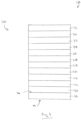
- the coated article 10 includes a substrate or first ply 12 having a first major surface 14 and an opposed second major surface 16.
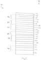
- a solar control coating 30 of the invention is located over at least one of the major surfaces 14, 16 of the first ply 12. In the examples shown in Figs. 1 and 2 , the solar control coating 30 is located over at least a portion of the second major surface 16 of the first ply 12. As shown in Fig. 1 , the solar control coating 30 comprises a first phase adjustment layer 40. A first metal functional layer 46 is located over the first phase adjustment layer 40. An optional first primer layer 48 can be located over the first metal functional layer 46. A second phase adjustment layer 50 is located over the optional first primer layer 48, if present. A second metal functional layer 58 is located over the second phase adjustment layer 50. An optional second primer layer 60 can be located over the second metal functional layer 58.
- a third phase adjustment layer 62 is located over the optional second primer layer 60, if present.
- a third metal functional layer 70 is located over the third phase adjustment layer 62.
- An optional third primer layer 72 can be located over the third metal functional layer 70.
- a fourth phase adjustment layer 86 is located over the optional third primer layer 72, if present.
- An optional protective layer 92 can be located over the fourth phase adjustment layer 86.
- At least the metal functional layers 58, 70 comprise a metal functional multi-film layer comprising (i) at least one infrared reflective film and (ii) at least one absorptive film.
- the first ply 12 can be transparent or translucent to visible radiation.
- transparent is meant having visible radiation transmittance of greater than 0% up to 100%.
- the ply can be translucent.
- translucent is meant diffusing visible radiation such that objects on the side opposite a viewer are not clearly visible.
- suitable materials include, but are not limited to, plastic substrates (such as acrylic polymers, such as polyacrylates; polyalkylmethacrylates, such as polymethylmethacrylates, polyethylmethacrylates, polypropylmethacrylates, and the like; polyurethanes; polycarbonates; polyalkylterephthalates, such as polyethyleneterephthalate (PET), polypropyleneterephthalates, polybutyleneterephthalates, and the like; polysiloxane-containing polymers; or copolymers of any monomers for preparing these, or any mixtures thereof); ceramic substrates; glass substrates; or mixtures or combinations of any of the above.
- plastic substrates such as acrylic polymers, such as polyacrylates; polyalkylmethacrylates, such as polymethylmethacrylates, polyethylmethacrylates, polypropylmethacrylates, and the like; polyurethanes; polycarbonates; polyalkylterephthalates, such as polyethyleneterephthal
- the ply can comprise conventional soda-lime-silicate glass, borosilicate glass, or leaded glass.
- the glass can be clear glass.
- clear glass is meant non-tinted or non-colored glass.
- the glass can be tinted or otherwise colored glass.
- the glass can be non-heat-treated or heat-treated glass.
- the glass can be of any type, such as conventional float glass, and can be of any composition having any optical properties, e.g., any value of visible radiation transmittance, ultraviolet radiation transmittance, infrared radiation transmittance, and/or total solar energy transmittance.
- float glass is meant glass formed by a conventional float process in which molten glass is deposited onto a molten metal bath and controllably cooled to form a float glass ribbon.
- the phase adjustment layers 40, 50, 62, 86 comprise nonmetallic layers.
- the phase adjustment layers 40, 50, 62, 86 comprise dielectric or semiconductor materials.
- the phase adjustment layers 40, 50, 62, 86 can comprise oxides, nitrides, oxynitrides, borides, carbides, oxycarbides, borocarbides, boronitrides, carbonitrides, and/or mixtures, combinations, blends, or alloys thereof.
- Particular examples of materials include zinc oxides, tin oxides, silicon nitrides, silicon-aluminum nitrides, silicon-nickel nitrides, silicon-chromium nitrides, antimony doped tin oxide, tin doped zinc oxide, aluminum doped zinc oxide, indium doped zinc oxide, titanium oxide, and/or mixtures, combinations, blends, or alloys thereof.
- phase adjustment layers 40, 50, 62, 86 can comprise a single material. Alternatively, one or more of the phase adjustment layers 40, 50, 62, 86 can comprise multiple materials and/or multiple films.
- the phase adjustment layers 40, 50, 62, 86 can comprise a stratified sequence of films of chemically distinct materials or phases and/or may comprise one or more composites of one or more chemically distinct materials or phases.
- the different phase adjustment layers 40, 50, 62, 86 can comprise the same or different materials.
- the phase adjustment layers 40, 50, 62, 86 can have the same or different thicknesses.
- phase adjustment layers 40, 50, 62, 86 allow adjustment of the constructive and destructive optical interference of electromagnetic radiation partially reflected from, and/or partially transmitted by, the various interface boundaries of the layers of the solar control coating 30. Varying the thicknesses and/or compositions of the phase adjustment layers 40, 50, 62, 86 can change the overall reflectance, transmittance, and/or absorptance of the solar control coating 30, which can alter the solar control performance, thermal infrared insulating performance, color, and/or aesthetics of the solar control coating 30. Additionally, the phase adjustment layers 40, 50, 62, 86 can provide chemical and/or mechanical protection for other layers of the solar control coating 30, such as the metal functional layers.
- phase adjustment layers 40, 50, 62, 86 can act as antireflective layers to antireflect the metal functional layers to reduce the overall visible light reflectance and/or increase the visible light transmittance of the solar control coating 30.
- Materials having refractive indices around 2 are particularly useful for antireflection of metal functional layers.
- the first phase adjustment layer 40 is located over at least a portion of the second major surface 16 of the first ply 12.
- the first phase adjustment layer 40 can be a single layer or can comprise one or more films of antireflective materials and/or dielectric materials described above.
- the first phase adjustment layer 40 can be transparent to visible light.
- the first phase adjustment layer 40 may or may not exhibit minimal absorption in one or more regions of the electromagnetic spectrum, for example, visible light.
- the first phase adjustment layer 40 can comprise any of the phase adjustment materials described above.
- the first phase adjustment layer 40 can comprise a metal oxide, a mixture of metal oxides, or a metal alloy oxide.
- the first phase adjustment layer 40 can comprise doped or non-doped oxides of zinc and tin.
- the first phase adjustment layer 40 can have an optical thickness in the range of 40 nm to 100 nm. For example, an optical thickness in the range of 50 nm to 90 nm. For example, an optical thickness in the range of 70 nm to 80 nm. For example, an optical thickness in the range of 75 nm to 76 nm.
- the first phase adjustment layer 40 can have a geometric thickness in the range of 20 nm to 50 nm. For example, a geometric thickness in the range of 25 nm to 45 nm. For example, a geometric thickness in the range of 35 nm to 40 nm. For example, a geometric thickness in the range of 37 nm to 38 nm.
- the first phase adjustment layer 40 can comprise a multi-film structure having a first film 42 and a second film 44.
- the second film 44 can be located over the first film 42.
- the first film 42 can comprise, for example, an oxide of a metal alloy or a mixture of metal oxides.
- the first film 42 can be an oxide of an alloy of zinc and tin.
- an alloy of zinc and tin is meant both true alloys and also mixtures.
- the oxide of an alloy of zinc and tin can be that obtained from magnetron sputtering vacuum deposition (MSVD) from a cathode of zinc and tin.
- the cathode can comprise zinc and tin in proportions of 5 wt.% to 95 wt.% zinc and 95 wt.% to 5 wt.% tin, such as 10 wt.% to 90 wt.% zinc and 90 wt.% to 10 wt.% tin.
- tin in proportions of 5 wt.% to 95 wt.% zinc and 95 wt.% to 5 wt.% tin, such as 10 wt.% to 90 wt.% zinc and 90 wt.% to 10 wt.% tin.
- An exemplary oxide of a metal alloy for the first film 42 can be written as Zn X Sn 1-X O 2-X (Formula 1) where "x" varies in the range of greater than 0 to less than 1. For instance, "x" can be greater than 0 and can be any fraction or decimal greater than 0 and less than 1.
- the stoichiometric form of Formula 1 is "Zn 2 SnO 4 ", commonly referred to as zinc stannate.
- a zinc stannate layer can be sputter deposited from a cathode having 52 wt.% zinc and 48 wt.% tin in the presence of oxygen.
- the first film 42 can comprise zinc stannate.
- a doped zinc oxide can be deposited from a zinc cathode that includes another material to improve the sputtering characteristics of the cathode.
- the zinc cathode can include a small amount of tin (e.g., up to 10 wt.%, such as up to 5 wt.%) to improve sputtering.
- the resultant zinc oxide film would include a small percentage of tin oxide, e.g., up to 10 wt.% tin oxide, e.g., up to 5 wt.% tin oxide.
- the other materials include aluminum, indium, and combinations thereof.
- the other material comprises tin.
- a tin doped zinc oxide material deposited from a cathode comprising 90 wt.% zinc and 10 wt.% tin, in the presence of oxygen, is referred to herein as ZnO 90/10.
- the second film 44 can comprise a metal oxide, a doped metal oxide, or an oxide mixture.
- the second film 44 can comprise a metal oxide or a doped metal oxide.
- the second film 44 can comprise zinc oxide or doped zinc oxide.
- the second film 44 can comprise tin doped zinc oxide.
- the second film 44 can comprise ZnO 90/10.
- the first film 42 can have an optical thickness in the range of 30 nm to 70 nm. For example, an optical thickness in the range of 40 nm to 60 nm. For example, an optical thickness in the range of 44 nm to 54 nm. For example, an optical thickness in the range of 49 nm to 52 nm.
- the first film 42 can have a geometric thickness in the range of 15 nm to 35 nm. For example, a geometric thickness in the range of 20 nm to 30 nm. For example, a geometric thickness in the range of 22 nm to 27 nm. For example, a geometric thickness in the range of 24 nm to 25 nm.
- the second film 44 can have an optical thickness in the range of 10 nm to 40 nm. For example, an optical thickness in the range of 16 nm to 38 nm. For example, an optical thickness in the range of 20 nm to 30 nm. For example, an optical thickness in the range of 26 nm to 28 nm.
- the metal functional layer 46can be a single film.
- the metal functional layer 46can comprise a continuous metal film.
- continuous metal film is meant an unbroken or non-disconnected film, such as a homogeneous film.
- the metal functional layers 58, 70 each comprise a metal functional multi-film layer.
- metal functional multi-film layer is meant a layer comprising (i) at least one infrared reflective film and (ii) at least one absorptive film.
- the infrared reflective film can have reflectivity in the solar infrared and/or thermal infrared portions of the electromagnetic spectrum.
- the absorptive film can exhibit enhanced absorptivity in one or more portions of the electromagnetic spectrum. For example, enhanced absorptivity in the visible radiation region and/or the infrared radiation region and/or the ultraviolet radiation region of the electromagnetic spectrum.
- a metal functional multi-film layer can comprise an absorptive film over an infrared reflective film.
- the absorptive film can be in direct contact with an overlying optional primer layer.
- a metal functional multi-film layer can comprise an infrared reflective film over an absorptive film.
- the absorptive film can be in direct contact with the underlying phase adjustment layer.
- infrared reflective films include continuous metal films.
- infrared reflective metals useful for the infrared reflective films include noble or near noble metals.
- metals include silver, gold, platinum, palladium, osmium, iridium, rhodium, ruthenium, copper, mercury, rhenium, aluminum, and combinations, mixtures, blends, or alloys thereof.
- one or more of the metal functional films can comprise a continuous metallic silver film.
- absorptive materials for the absorptive film include metals, such as gold, silver, copper, nickel, palladium, platinum, tungsten, rhodium, iridium, tantalum, iron, tin, aluminum, lead, zinc, chromium, molybdenum, niobium, cobalt, manganese, titanium, silicon, chromium, and combinations, mixtures, blends, or alloys thereof.
- one or more of the absorptive films can comprise copper.
- One or more of the absorptive films can comprise alloys or super alloys of two or more of the above materials.
- alloys of nickel, chromium, or nickel and chromium For example, Inconel ® 600, Inconel ® 617, Inconel ® 625, Inconel ® 690, and/or Inconel ® 718.
- the first metal functional layer 46 can comprise a metal functional multi-film layer as described above.
- the first metal functional layer 46 can comprise a single infrared reflective film comprising any of the above infrared reflective metals.
- the first metal functional layer 46 can comprise a continuous film of metallic silver.
- the first metal functional layer 46 can have a geometric thickness in the range of 5 nm to 25 nm. For example, a geometric thickness in the range of 7 nm to 20 nm. For example, a geometric thickness in the range of 10 nm to 15 nm. For example, a geometric thickness in the range of 11.5 nm to 12.5 nm.
- Optional primer layers 48, 60, 72 can be located in direct contact with the associated underlying metal functional layers.
- the primer layers 48, 60, 72 protect the associated metal functional layers during the coating process and/or subsequent processing, such as thermal tempering.
- the primer material is deposited as a metal.
- subsequent processing such as the deposition of the overlying phase adjustment layer and/or thermal tempering, some or all of the metal primer oxidizes.
- oxide or nitride materials are used in the phase adjustment layers, the primer layers 48, 60, 72 can comprise oxophillic or nitrophillic materials, respectively.
- the primer layers 48, 60, 72 need not be all the same material.
- the primer layers 48, 60, 72 need not be of the same thickness.
- Examples of materials useful for the primer layers 48, 60, 72 include titanium, niobium, tungsten, nickel, chromium, iron, tantalum, zirconium, aluminum, silicon, indium, tin, zinc, molybdenum, hafnium, bismuth, vanadium, manganese, and combinations, mixtures, blends, or alloys thereof.
- the optional first primer layer 48 can be located over the first metal functional layer 46.
- the first primer layer 48 can be a single film or a multiple film layer.
- the first primer layer 48 can comprise any of the primer materials described above.
- the first primer layer 48 can comprise titanium.
- the first primer layer 48 can be deposited as titanium metal.
- the first primer layer 48 can have a geometric thickness or effective thickness in the range of 0.5 nm to 10 nm. For example, in the range of 1 nm to 5 nm. For example, in the range of 1.5 nm to 2.5 nm. For example, 2 nm.
- the second phase adjustment layer 50 is located over the first metal functional layer, such as over the optional first primer layer 48, if present.
- the second phase adjustment layer 50 can comprise one or more of the phase adjustment materials and/or films described above for the phase adjustment layers.
- the first film 52 and/or the third film 56 can comprise a metal oxide or a doped metal oxide.
- the first film 52 and/or the third film 56 can comprise zinc oxide or doped zinc oxide.
- the first film 52 and/or the third film 56 can comprise tin doped zinc oxide.
- the first film 52 and/or the third film 56 can comprise ZnO 90/10.
- the second film 54 can comprise an oxide of a metal alloy.
- the second film 54 can comprise zinc stannate.
- the first film 52 (and/or the third film 56) can have an optical thickness in the range of 10 nm to 40 nm. For example, an optical thickness in the range of 16 nm to 38 nm. For example, an optical thickness in the range of 20 nm to 35 nm. For example, an optical thickness in the range of 28 nm to 30 nm.
- the first film 52 and the third film 56 can comprise the same or different materials and can be of the same or different thickness.
- the first film 52 (and/or third film 56) can have a geometric thickness in the range of 5 nm to 20 nm. For example, a geometric thickness in the range of 8 nm to 18 nm. For example, a geometric thickness in the range of 10 nm to 16 nm. For example, a geometric thickness in the range of 14 nm to 15 nm.
- the second film 54 can have an optical thickness in the range of 50 nm to 100 nm. For example, an optical thickness in the range of 70 nm to 90 nm. For example, an optical thickness in the range of 76 nm to 80 nm. For example, an optical thickness in the range of 78 nm to 79 nm.
- the second metal functional layer 58 is located over the second phase adjustment layer 50.
- the second metal functional layer 58 comprises a multi-film layer.
- the second metal functional layer 58 is a metal functional multi-film layer comprising the infrared reflective film 57 and an absorptive film 59.
- the absorptive film 59 can be located over or under the infrared reflective film 57.
- the absorptive film 59 is located over the infrared reflective film 57.
- the infrared reflective film 57 comprises any of the infrared reflective materials described above.
- a continuous metal film For example, a continuous silver film.
- the infrared reflective film 57 can have a geometric thickness in the range of 5 nm to 25 nm. For example, a geometric thickness in the range of 7 nm to 20 nm. For example, a geometric thickness in the range of 10 nm to 18 nm. For example, a geometric thickness in the range of 15 nm to 16 nm.
- the absorptive film 59 comprises an alloy of nickel and chromium.
- the absorptive film 59 can comprise Inconel ® 600, Inconel ® 617, Inconel ® 625, Inconel ® 690, and/or Inconel ® 718.
- the absorptive film 59 can comprise Inconel ® 600.
- the absorptive film 59 can have an effective thickness in the range of 0 nm to 2 nm. For example, an effective thickness in the range of 0.1 nm to 1.5 nm. For example, an effective thickness in the range of 0.25 nm to 1 nm. For example, an effective thickness in the range of 0.5 nm to 0.75 nm.
- the optional second primer layer 60 can be located over the second metal functional layer 58.
- the second primer layer 60 can include of any of the primer materials and can be any of the thicknesses described above with respect to the optional first primer layer 48.
- the second primer 60 can comprise titanium.
- the second primer layer 60 can have a geometric thickness or effective thickness in the range of 0.5 nm to 10 nm. For example, a geometric thickness or effective thickness in the range of 1 nm to 5 nm. For example, a geometric thickness or effective thickness in the range of 1.5 nm to 2.5 nm. For example, a geometric thickness or effective thickness in the range of 2 nm to 2.25 nm.
- the third phase adjustment layer 62 can have an optical thickness in the range of 90 nm to 200 nm. For example, an optical thickness in the range of 120 nm to 180 nm. For example, an optical thickness in the range of 150 nm to 170 nm. For example, an optical thickness in the range of 158 nm to 159 nm.
- the third phase adjustment layer 62 can have a geometric thickness in the range of 45 nm to 100 nm. For example, a geometric thickness in the range of 60 nm to 90 nm. For example, a geometric thickness in the range of 75 nm to 85 nm. For example, a geometric thickness in the range of 79 nm to 80 nm.
- the first film 64 (and/or third film 68) can have an optical thickness in the range of 10 nm to 40 nm. For example, an optical thickness in the range of 16 nm to 38 nm. For example, an optical thickness in the range of 20 nm to 30 nm. For example, an optical thickness in the range of 28 nm to 29 nm.
- the first film 64 and the third film 68 can be of the same or different thickness.
- the first film 64 (and/or third film 68) can have a geometric thickness in the range of 5 nm to 20 nm. For example, a geometric thickness in the range of 8 nm to 18 nm. For example, a geometric thickness in the range of 10 nm to 15 nm. For example, a geometric thickness in the range of 13 nm to 14 nm.
- the third metal functional layer 70 comprises a multi-film structure.
- the third metal functional layer 70 is a metal functional multi-film layer comprising an absorptive film 71 and an infrared reflective film 73.
- the metal functional multi-film layer of the third metal functional layer 70 can have any of the film orientations described above for the second metal functional layer 58.
- the absorptive film 71 can be located over or under the infrared reflective film 73.
- the absorptive film 71 can be located under the infrared reflective film 73.
- the absorptive film 71 can be a metallic film.
- the absorptive film 71 comprises copper.
- the absorptive film 71 can optionally further comprise gold, silver, nickel, iron, tin, aluminum, lead, zinc, chromium and combinations thereof.
- the absorptive film 71 can have a physical or effective thickness in the range of 1 nm to 10 nm. For example, in the range of 2.5 nm to 4.5 nm. For example, in the range of 3 nm to 4 nm. For example, in the range of 3.5 nm to 3.75 nm.
- the infrared reflective film 73 can be a continuous metal film.
- a continuous metallic film for example, a metallic silver film.
- the optional third primer layer 72 can include any of the primer materials described above.
- the third primer layer 72 can comprise titanium.
- the third primer layer 72 can have a geometric thickness or effective thickness in the range of 0.5 nm to 10 nm. For example, in the range of 1 nm to 5 nm. For example, in the range of 1.5 nm to 2.5 nm. For example, in the range of 2 nm to 2.3 nm.
- the fourth phase adjustment layer 86 can comprise one or more of the phase adjustment materials and/or films discussed above with respect to the first, second, or third phase adjustment layers 40, 50, 62.
- the fourth phase adjustment layer 86 can have an optical thickness in the range of 30 nm to 100 nm. For example, an optical thickness in the range of 40 nm to 80 nm. For example, an optical thickness in the range of 50 nm to 70 nm. For example, an optical thickness in the range of 58 nm to 59 nm.
- the fourth phase adjustment layer 86 can have a geometric thickness in the range of 15 nm to 50 nm. For example, a geometric thickness in the range of 20 nm to 40 nm. For example, a geometric thickness in the range of 25 nm to 35 nm. For example, a geometric thickness in the range of 29 nm to 30 nm.
- the fourth phase adjustment layer 86 can comprise a first film 88 and a second film 90.
- the first film 88 can comprise a metal oxide or a doped metal oxide.
- a metal oxide or a doped metal oxide for example, zinc oxide or doped zinc oxide.
- tin doped zinc oxide for example, ZnO 90/10.
- the second film 90 can comprise an oxide of a metal alloy.
- an oxide comprising zinc and tin for example, zinc stannate.
- the first film 88 can have an optical thickness in the range of 4 nm to 40 nm. For example, an optical thickness in the range of 10 nm to 30 nm. For example, an optical thickness in the range of 14 nm to 22 nm. For example, an optical thickness in the range of 18 nm to 19 nm.
- the first film 88 can have a geometric thickness in the range of 2 nm to 20 nm. For example, a geometric thickness in the range of 5 nm to 15 nm. For example, a geometric thickness in the range of 7 nm to 11 nm. For example, a geometric thickness in the range of 9 nm to 10 nm.
- the second film 90 can have an optical thickness in the range of 10 nm to 80 nm. For example, an optical thickness in the range of 20 nm to 60 nm. For example, an optical thickness in the range of 30 nm to 50 nm. For example, an optical thickness in the range of 40 nm to 45 nm.
- the optional protective layer 92 can be the terminal layer of the solar control coating 30.
- the optional protective layer 92 can comprise one or more nonmetallic materials, such as those described above with regard to the phase adjustment layers.
- the protective layer 92 can comprise a metal material.
- the optional protective layer 92 can provide chemical and/or mechanical protection to the underlying coating layers.
- the optional protective layer 92 can provide phase adjustment and/or absorption.
- the protective layer 92 can be a single film or have a multi-film structure.
- one or more other optional protective layers 92 can be located within the solar control coating 30. For example, between two or more of the phase adjustment layers.
- the optional protective layer 92 can include, for example, a metal oxide or metal nitride material.
- the protective layer 92 can comprise an oxide of titanium, for example titanium dioxide (i.e., titania).
- the optional protective layer 92 can have an optical thickness in the range of 1 nm to 30 nm. For example, an optical thickness in the range of 2 nm to 20 nm. For example, an optical thickness in the range of 4 nm to 14 nm. For example, an optical thickness in the range of 10 nm to 12 nm.
- the optional protective layer 92 can have a geometric thickness or effective thickness in the range of 0.5 nm to 15 nm. For example, in the range of 1 nm to 10 nm. For example, in the range of 2 nm to 7 nm. For example, in the range of 5 nm to 6 nm.
- the solar control coating 30 can be a non-heat-treated coating.
- the layers and/or films of the solar control coating 30 can be formed by any conventional method. Examples of such methods include conventional chemical vapor deposition (CVD) and/or physical vapor deposition (PVD) methods. Examples of CVD processes include spray pyrolysis. Examples of PVD processes include electron beam evaporation and vacuum sputtering, such as magnetron sputter vapor deposition (MSVD). Other coating methods could also be used, such as, but not limited to, sol-gel deposition. One or more layers or films can be formed by one method and one or more other layers or films can be formed by a different method. For example, the coating 30 can be formed by MSVD.
- CVD chemical vapor deposition
- PVD physical vapor deposition
- MSVD magnetron sputter vapor deposition
- Other coating methods could also be used, such as, but not limited to, sol-gel deposition.
- One or more layers or films can be formed by one method and one or more other layers or films can be formed by a different method.
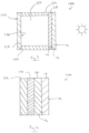
- Fig. 3 shows the coated article 10 of Figs. 1 and 2 incorporated into an insulating glass unit (IGU) 100.
- the first major surface 14 (No. 1 surface) faces the building exterior, i.e., is an outer major surface
- the second major surface 16 faces the interior of the building.
- the insulating glass unit 100 includes a second ply 118 having an outwardly facing major surface 120 (No. 3 surface) and an inwardly facing major surface 122 (No. 4 surface). This numbering of the ply surfaces is in keeping with conventional practice in the fenestration art.
- the second ply 118 is spaced from the first ply 12.
- the first and second plies 12, 118 can be connected together in any suitable manner, such as by being adhesively bonded to a conventional spacer frame 124.
- a gap or chamber 126 is formed between the two plies 12, 118.
- the chamber 126 can be filled with a selected atmosphere, such as gas, for example, air or a non-reactive gas such as argon or krypton gas.
- the solar control coating 30 located on the No. 2 surface 16.
- the solar control coating 30 could be located on any of the other surfaces.
- the solar control coating 30 could be located on the No. 3 surface 120.
- the solar control coating 30 could be located on the No. 1 surface 14 or the No. 4 surface 122.
- the second ply 118 can be of any of the materials described above for the first ply 12.
- the second ply 118 can be the same as the first ply 12 or the second ply 118 can be different than the first ply 12.
- the first and second plies 12, 118 can each be, for example, clear float glass or can be tinted or colored glass or one ply 12, 118 can be clear glass and the other ply 12, 118 colored glass.
- Fig. 4 shows the coated article 10 incorporated into a laminated unit 130.
- the laminated unit 130 includes the first ply 12 and the second ply 118 connected by a polymeric interlayer 132.
- the solar control coating 30 is shown on the No. 2 surface 16. However, as with the IGU 100 described above, the solar control coating 30 could be on any of the surfaces 14, 16, 120, or 122.
- the solar control coating 30 provides a 3 mm reference IGU SHGC of not greater than 0.3.
- the solar control coating 30 provides a 3 mm reference IGU SHGC in the range of 0.2 to 0.3.
- 0.2 to 0.29 such as 0.2 to 0.26, such as 0.2 to 0.24, such as 0.21 to 0.25.
- 0.22 to 0.235 In the range of 0.22 to 0.235.
- the solar control coating 30 provides a 3 mm reference IGU visible light transmittance of not greater than 70%.
- not greater than 65% For example, not greater than 60%.
- not greater than 57% For example, not greater than 55%.
- in the range of 40% to 65% for example, in the range of 50% to 55%.
- the solar control coating 30 provides a 3 mm reference IGU visible light exterior reflectance of not greater than 25%. For example, not greater than 20%. For example, not greater than 15%. For example, not greater than 14%. For example, in the range of 10% to 15%. For example, in the range of 12% to 13.5%.
- the solar control coating 30 provides a 3 mm reference IGU visible light interior reflectance of not greater than 25%. For example, not greater than 22%. For example, not greater than 20%. For example, in the range of 16% to 22%. For example, in the range of 18% to 20%.
- the solar control coating 30 provides a 3 mm reference IGU LSG ratio of at least 1.8. For example, at least 1.85. For example, at least 1.9. For example, at least 2. For example, in the range of 1.6 to 2.5. For example, in the range of 2.1 to 2.4. For example, in the range of 2.2 to 2.37.
- the solar control coating 30 provides a 3 mm reference IGU transmitted L* in the range of 74 to 80. For example in the range of 75 to 79. For example in the range of 76.5 to 78.5.
- the solar control coating 30 provides a 3 mm reference IGU transmitted a* in the range of -6 to -3. For example in the range of -5.5 to -4. For example in the range of -5.2 to -4.25.
- the solar control coating 30 provides a 3 mm reference IGU transmitted b* in the range of 0 to 6. For example in the range of 1 to 5. For example in the range of 2.8 to 4.8.
- the solar control coating 30 provides a 3 mm reference IGU exterior reflected L* in the range of 30 to 50. For example in the range of 35 to 49. For example in the range of 41.9 to 43.2.
- the solar control coating 30 provides a 3 mm reference IGU exterior reflected a* in the range of -4 to 0. For example in the range of -3 to -1. For example in the range of - 2.7 to -1.8.
- the solar control coating 30 provides a 3 mm reference IGU exterior reflected b* in the range of -7 to 0. For example in the range of -6 to -1. For example in the range of - 5.6 to -4.1.
- the solar control coating 30 provides a 3 mm reference IGU interior reflected L* in the range of 35 to 55. For example in the range of 40 to 52. For example in the range of 48 to 52.
- the solar control coating 30 provides a 3 mm reference IGU interior reflected a* in the range of -8 to 0. For example in the range of -6.2 to -1. For example in the range of - 5.9 to -4.5.
- the solar control coating 30 provides a 3 mm reference IGU interior reflected b* in the range of -5 to 0. For example in the range of -4 to -1. For example in the range of - 3.5 to -2.
- the solar control coating 30 provides a sheet resistance of less than 10 ohms per square ( ⁇ / ⁇ ). For example, less than 5 ⁇ / ⁇ . For example, less than 2 ⁇ / ⁇ . For example, less than 1 ⁇ / ⁇ . For example, in the range of greater than 0 to 1.5. For example, in the range of greater than 0 to 1.
- the solar control coating 30 can have an emissivity in the range of 0.02 to 0.04. For example, in the range of 0.023 to 0.037.
- the solar control coating 30 provides a 3 mm reference IGU Winter/night U factor in the range of 0.9 to 3 Watt per square meter Kelvin (W/m2-K). For example, in the range of 1 to 2.5 W/m2-K. For example, in the range of 1.5 to 1.7 W/m2-K. For example, in the range of 1.6 to 1.67 W/m2-K.
- W/m2-K Watt per square meter Kelvin
- the solar control coating 30 provides a reference laminated unit transmitted L* in the range of 65 to 85. For example, in the range of 72 to 80. For example, in the range of 75 to 77.
- the solar control coating 30 provides a reference laminated unit reflected (exterior) L* in the range of 40 to 55. For example, in the range of 44 to 50. For example, in the range of 45.5 to 47.5.
- the solar control coating 30 provides a reference laminated unit reflected (exterior) a* in the range of -6 to -16. For example, in the range of -8 to -15. For example, in the range of -10 to -12.
- the solar control coating 30 provides a reference laminated unit reflected (exterior) b* in the range of 0 to -8. For example, in the range of -2 to -6. For example, in the range of -3 to -5.
Landscapes
- Chemical & Material Sciences (AREA)
- Life Sciences & Earth Sciences (AREA)
- Engineering & Computer Science (AREA)
- Chemical Kinetics & Catalysis (AREA)
- General Chemical & Material Sciences (AREA)
- Geochemistry & Mineralogy (AREA)
- Materials Engineering (AREA)
- Organic Chemistry (AREA)
- Physics & Mathematics (AREA)
- General Physics & Mathematics (AREA)
- Optics & Photonics (AREA)
- Laminated Bodies (AREA)
- Surface Treatment Of Glass (AREA)
- Optical Filters (AREA)
- Joining Of Glass To Other Materials (AREA)
- Optical Elements Other Than Lenses (AREA)
Claims (11)
- Article revêtu (10) comprenant :un substrat (12) ; etun revêtement solaire comprenant :une première couche d'ajustement de phase (40),une première couche fonctionnelle métallique (46) située sur la première couche d'ajustement de phase (40),en option une première couche primaire (48) située sur la première couche fonctionnelle métallique (46),une deuxième couche d'ajustement de phase (50) située sur la première couche primaire optionnelle (48),une deuxième couche fonctionnelle métallique (58) située sur la deuxième couche d'ajustement de phase (50),en option une deuxième couche primaire (60) située sur la deuxième couche fonctionnelle métallique (58),une troisième couche d'ajustement de phase (62) située sur la deuxième couche primaire optionnelle (60),une troisième couche fonctionnelle métallique (70) située sur la troisième couche d'ajustement de phase (62),en option une troisième couche primaire (72) située sur la troisième couche fonctionnelle métallique (70),une quatrième couche d'ajustement de phase (86) située sur la troisième couche primaire optionnelle (72), eten option une couche protectrice (92) située sur la quatrième couche d'ajustement de phase (86),dans lequel les couches d'ajustement de phase (40, 50, 62, 86) comprennent des matériaux diélectriques ou semiconducteurs,dans lequel la deuxième couche fonctionnelle métallique (58) comprend une couche multifilm fonctionnelle métallique comprenant (i) un film réflecteur infrarouge (57) et (ii) un film absorbant (59) comprenant un alliage de nickel et de chrome, etdans lequel la troisième couche fonctionnelle métallique (70) comprend une couche multifilm fonctionnelle métallique comprenant (i) au moins un film réflecteur infrarouge (73) et (ii) au moins un film absorbant (71) comprenant du cuivre.
- Article revêtu (10) selon la revendication 1, dans lequel la première couche fonctionnelle métallique (46) comprend un film simple ayant une épaisseur géométrique comprise dans l'intervalle de 5 nm à 25 nm, de préférence une épaisseur géométrique comprise dans l'intervalle de 7 nm à 20 nm, et mieux encore une épaisseur géométrique comprise dans l'intervalle de 10 nm à 15 nm.
- Article revêtu (10) selon la revendication 1 ou 2, dans lequel le film réflecteur infrarouge (57) de la deuxième couche fonctionnelle métallique (58) comprend de l'argent.
- Article revêtu (10) selon l'une quelconque des revendications 1 à 3, dans lequel le film réflecteur infrarouge (57) a une épaisseur géométrique comprise dans l'intervalle de 5 nm à 25 nm, de préférence une épaisseur géométrique comprise dans l'intervalle de 7 nm à 20 nm, et mieux encore une épaisseur géométrique comprise dans l'intervalle de 10 nm à 18 nm.
- Article revêtu (10) selon l'une quelconque des revendications 1 à 4, dans lequel le film absorbant (59) a une épaisseur géométrique comprise dans l'intervalle de 0,1 nm à 1,5 nm, de préférence une épaisseur géométrique comprise dans l'intervalle de 0,25 nm à 1 nm.
- Article revêtu (10) selon l'une quelconque des revendications 1 à 5, dans lequel ledit au moins un film réflecteur infrarouge (73) de la troisième couche fonctionnelle métallique (70) comprend un film d'argent métallique.
- Article revêtu (10) selon l'une quelconque des revendications 1 à 6, dans lequel :la première couche d'ajustement de phase (40) a une épaisseur optique comprise dans l'intervalle de 40 nm à 100 nm, de préférence une épaisseur optique comprise dans l'intervalle de 50 nm à 90 nm, et mieux encore une épaisseur optique comprise dans l'intervalle de 70 nm à 80 nm ;la deuxième couche d'ajustement de phase (50) a une épaisseur optique comprise dans l'intervalle de 80 nm à 200 nm, de préférence une épaisseur optique comprise dans l'intervalle de 100 nm à 160 nm, et mieux encore une épaisseur optique comprise dans l'intervalle de 130 nm à 140 nm ;la troisième couche d'ajustement de phase (62) a une épaisseur optique comprise dans l'intervalle de 90 nm à 200 nm, de préférence une épaisseur optique comprise dans l'intervalle de 120 nm à 180 nm, et mieux encore une épaisseur optique comprise dans l'intervalle de 150 nm à 170 nm ; etla quatrième couche d'ajustement de phase (86) a une épaisseur optique comprise dans l'intervalle de 30 nm à 100 nm, de préférence une épaisseur optique comprise dans l'intervalle de 40 nm à 80 nm, et mieux encore une épaisseur optique comprise dans l'intervalle de 50 nm à 70 nm.
- Article revêtu (10) selon l'une quelconque des revendications 1 à 7, dans lequel le revêtement solaire (30) comprend la couche protectrice (92), dans lequel la couche protectrice (92) a une épaisseur optique comprise dans l'intervalle de 1 nm à 30 nm, de préférence une épaisseur optique comprise dans l'intervalle de 2 nm à 20 nm, et mieux encore une épaisseur optique comprise dans l'intervalle de 4 nm à 14 nm.
- Article revêtu (10) selon l'une quelconque des revendications 1 à 8, dans lequel le revêtement solaire (30) donne un CGCS, pour un vitrage isolant de référence de 3 mm, ne dépassant pas 0,3, par exemple dans l'intervalle de 0,21 à 0,25.
- Article revêtu (10) selon l'une quelconque des revendications 1 à 9, dans lequel le revêtement solaire (30) donne un rapport LSG, pour un vitrage isolant de référence de 3 mm, compris dans l'intervalle de 1,6 à 2,5, de préférence de 2,1 à 2,4.
- Vitrage isolant (IGU) (100) comprenant le revêtement solaire (30) de l'une quelconque des revendications 1 à 10.
Applications Claiming Priority (4)
| Application Number | Priority Date | Filing Date | Title |
|---|---|---|---|
| US201562212665P | 2015-09-01 | 2015-09-01 | |
| US201662311440P | 2016-03-22 | 2016-03-22 | |
| US15/251,025 US10539726B2 (en) | 2015-09-01 | 2016-08-30 | Solar control coating with enhanced solar control performance |
| PCT/US2016/049554 WO2017040563A1 (fr) | 2015-09-01 | 2016-08-31 | Revêtement de contrôle solaire à performances améliorées de contrôle solaire |
Publications (3)
| Publication Number | Publication Date |
|---|---|
| EP3344591A1 EP3344591A1 (fr) | 2018-07-11 |
| EP3344591C0 EP3344591C0 (fr) | 2025-03-26 |
| EP3344591B1 true EP3344591B1 (fr) | 2025-03-26 |
Family
ID=58097933
Family Applications (1)
| Application Number | Title | Priority Date | Filing Date |
|---|---|---|---|
| EP16771027.6A Active EP3344591B1 (fr) | 2015-09-01 | 2016-08-31 | Revêtement de contrôle solaire à performances améliorées de contrôle solaire |
Country Status (10)
| Country | Link |
|---|---|
| US (3) | US10539726B2 (fr) |
| EP (1) | EP3344591B1 (fr) |
| JP (3) | JP2018528892A (fr) |
| KR (1) | KR102170018B1 (fr) |
| CN (2) | CN108137394A (fr) |
| CA (1) | CA2997104C (fr) |
| CO (1) | CO2018002372A2 (fr) |
| MX (1) | MX2018002369A (fr) |
| RU (1) | RU2719816C2 (fr) |
| WO (1) | WO2017040563A1 (fr) |
Families Citing this family (22)
| Publication number | Priority date | Publication date | Assignee | Title |
|---|---|---|---|---|
| US9932267B2 (en) | 2010-03-29 | 2018-04-03 | Vitro, S.A.B. De C.V. | Solar control coatings with discontinuous metal layer |
| US10654747B2 (en) * | 2010-03-29 | 2020-05-19 | Vitro Flat Glass Llc | Solar control coatings with subcritical copper |
| US10654748B2 (en) | 2010-03-29 | 2020-05-19 | Vitro Flat Glass Llc | Solar control coatings providing increased absorption or tint |
| US10539726B2 (en) * | 2015-09-01 | 2020-01-21 | Vitro Flat Glass Llc | Solar control coating with enhanced solar control performance |
| US10618252B2 (en) * | 2017-04-12 | 2020-04-14 | Vitro Flat Glass Llc | Solar control coating for laminated glazing |
| US11137527B2 (en) * | 2017-05-22 | 2021-10-05 | Viavi Solutions Inc. | Mixed spacer multispectral filter |
| US10788667B2 (en) | 2017-08-31 | 2020-09-29 | Vitro Flat Glass Llc | Heads-up display and coating therefor |
| US10921495B2 (en) | 2017-12-29 | 2021-02-16 | Vitro Flat Glass Llc | Solar control coatings and methods of forming solar control coatings |
| US11078718B2 (en) | 2018-02-05 | 2021-08-03 | Vitro Flat Glass Llc | Solar control coatings with quadruple metallic layers |
| US11427731B2 (en) * | 2018-03-23 | 2022-08-30 | Teledyne Micralyne, Inc. | Adhesive silicon oxynitride film |
| US10830933B2 (en) | 2018-06-12 | 2020-11-10 | Guardian Glass, LLC | Matrix-embedded metamaterial coating, coated article having matrix-embedded metamaterial coating, and/or method of making the same |
| US10562812B2 (en) | 2018-06-12 | 2020-02-18 | Guardian Glass, LLC | Coated article having metamaterial-inclusive layer, coating having metamaterial-inclusive layer, and/or method of making the same |
| GB201820002D0 (en) | 2018-12-07 | 2019-01-23 | Pilkington Group Ltd | Coated glass pane |
| CN113678032B (zh) * | 2019-03-28 | 2025-02-28 | 维特罗平板玻璃有限责任公司 | 具有高可见光反射和中性色的制品 |
| US12284770B2 (en) | 2020-02-14 | 2025-04-22 | Vitro Flat Glass Llc | Low sheet resistance coating |
| WO2023275793A1 (fr) * | 2021-06-29 | 2023-01-05 | Agp America S.A. | Revêtement solaire amélioré, procédé de fabrication et stratifié en verre comprenant un tel revêtement |
| CN114721077B (zh) * | 2022-03-23 | 2025-09-16 | 苏州大学 | 一种基于多层过渡金属层的超宽带光学吸收器 |
| WO2024141515A1 (fr) * | 2022-12-30 | 2024-07-04 | Agp Worldwide Operations Gmbh | Vitrage à revêtement à faible émissivité et contrôle de couleur |
| WO2024249073A1 (fr) | 2023-06-02 | 2024-12-05 | Vitro Flat Glass Llc | Composition de verre à faible teneur en fer et à faible redox |
| US20250206660A1 (en) * | 2023-12-21 | 2025-06-26 | Vitro Flat Glass Llc | Solar Control Coating With Enhanced Solar Heat Gain |
| WO2025199629A1 (fr) * | 2024-03-28 | 2025-10-02 | 3E Nano Inc. | Structure d'isolation thermique transparente |
| WO2026039267A1 (fr) | 2024-08-15 | 2026-02-19 | Vitro Flat Glass Llc | Vitre teintée |
Citations (1)
| Publication number | Priority date | Publication date | Assignee | Title |
|---|---|---|---|---|
| DE102012207561A1 (de) * | 2012-05-07 | 2013-11-07 | Von Ardenne Anlagentechnik Gmbh | IR-reflektierendes, transparentes Schichtsystem und Verfahren zu dessen Herstellung |
Family Cites Families (42)
| Publication number | Priority date | Publication date | Assignee | Title |
|---|---|---|---|---|
| DE2203943C2 (de) | 1972-01-28 | 1974-02-21 | Flachglas Ag Delog-Detag, 8510 Fuerth | Wärmerefexionsscheibe, die gute Farbgleichmäßigkeit aufweist, Verfahren zu ihrer Herstellung sowie ihre Verwendung |
| US4286009A (en) * | 1978-02-16 | 1981-08-25 | Corning Glass Works | Composite solar absorber coatings |
| US4437455A (en) * | 1982-05-03 | 1984-03-20 | Engelhard Corporation | Stabilization of solar films against hi temperature deactivation |
| CA2129488C (fr) * | 1993-08-12 | 2004-11-23 | Olivier Guiselin | Substrats transparents munis d'un empilement de couches minces, application aux vitrages d'isolation thermique et/ou de protection solaire |
| FR2757151B1 (fr) * | 1996-12-12 | 1999-01-08 | Saint Gobain Vitrage | Vitrage comprenant un substrat muni d'un empilement de couches minces pour la protection solaire et/ou l'isolation thermique |
| US20020136905A1 (en) * | 1999-11-24 | 2002-09-26 | Medwick Paul A. | Low shading coefficient and low emissivity coatings and coated articles |
| JP4949609B2 (ja) * | 2002-02-11 | 2012-06-13 | ピーピージー・インダストリーズ・オハイオ・インコーポレイテッド | 日射コントロール被覆 |
| WO2003093188A1 (fr) | 2002-05-03 | 2003-11-13 | Ppg Industries Ohio, Inc. | Substrat presentant un revetement de gestion thermique pour une unite de vitrage isolant |
| CN1777690B (zh) * | 2003-03-28 | 2010-11-03 | Ppg工业俄亥俄公司 | 采用钛与铝材料的混合物涂覆的衬底,制备该衬底的方法和钛与铝金属的阴极靶材 |
| EP1498397A1 (fr) * | 2003-07-16 | 2005-01-19 | Glaverbel | Substrat revêtu à très faible facteur solaire |
| US20050238923A1 (en) * | 2004-04-27 | 2005-10-27 | Thiel James P | Hybrid coating stack |
| CN101066011A (zh) | 2004-11-30 | 2007-10-31 | 旭硝子株式会社 | 导电性层积体、等离子显示器用的电磁波屏蔽膜及保护板 |
| EP1833768B1 (fr) * | 2004-12-21 | 2012-06-13 | AGC Glass Europe | Feuille de verre portant un empilage multi-couches |
| US7473471B2 (en) | 2005-03-21 | 2009-01-06 | Ppg Industries Ohio, Inc. | Coating composition with solar properties |
| HUE043749T2 (hu) * | 2005-05-11 | 2019-09-30 | Agc Glass Europe | Napfényvédõ rétegrendszer |
| FR2893024B1 (fr) * | 2005-11-08 | 2008-02-29 | Saint Gobain | Substrat muni d'un empilement a proprietes thermiques |
| US7342716B2 (en) * | 2005-10-11 | 2008-03-11 | Cardinal Cg Company | Multiple cavity low-emissivity coatings |
| US7572511B2 (en) * | 2005-10-11 | 2009-08-11 | Cardinal Cg Company | High infrared reflection coatings |
| FR2893023B1 (fr) * | 2005-11-08 | 2007-12-21 | Saint Gobain | Substrat muni d'un empilement a proprietes thermiques |
| US8025957B2 (en) * | 2007-05-09 | 2011-09-27 | Ppg Industries Ohio, Inc. | Vehicle transparency |
| FR2936510B1 (fr) | 2008-09-30 | 2019-08-30 | Saint-Gobain Glass France | Substrat muni d'un empilement a proprietes thermiques, en particulier pour realiser un vitrage chauffant. |
| ES2316321B2 (es) * | 2008-10-20 | 2010-12-14 | Abengoa Solar New Technologies, S.A. | Recubrimiento absorbente selectivo solar y metodo de fabricacion. |
| BR112012021760A2 (pt) * | 2010-03-01 | 2016-05-10 | Cpfilms Inc | películas de janela de baixa emissividade e blindagem de emi |
| US9932267B2 (en) * | 2010-03-29 | 2018-04-03 | Vitro, S.A.B. De C.V. | Solar control coatings with discontinuous metal layer |
| US8865325B2 (en) * | 2010-03-29 | 2014-10-21 | Ppg Industries Ohio, Inc. | Tempered and non-tempered glass coatings having similar optical characteristics |
| US10654747B2 (en) * | 2010-03-29 | 2020-05-19 | Vitro Flat Glass Llc | Solar control coatings with subcritical copper |
| US10654748B2 (en) * | 2010-03-29 | 2020-05-19 | Vitro Flat Glass Llc | Solar control coatings providing increased absorption or tint |
| US8337988B2 (en) | 2010-04-22 | 2012-12-25 | Centre Luxembourgeois De Recherches Pour Le Verre Et La Ceramique S.A. (C.R.V.C.) | Coated article having low-E coating with absorber layer(s) |
| US9028956B2 (en) * | 2010-04-22 | 2015-05-12 | Centre Luxembourgeois De Recherches Pour Le Verre Et La Ceramique S.A. (C.R.V.C.) | Coated article having low-E coating with absorber layer(s) |
| BE1019345A3 (fr) * | 2010-05-25 | 2012-06-05 | Agc Glass Europe | Vitrage de controle solaire a faible facteur solaire. |
| US8557391B2 (en) | 2011-02-24 | 2013-10-15 | Guardian Industries Corp. | Coated article including low-emissivity coating, insulating glass unit including coated article, and/or methods of making the same |
| FR2981646B1 (fr) * | 2011-10-21 | 2013-10-25 | Saint Gobain | Vitrage de controle solaire comprenant une couche d'un alliage nicu |
| BE1020331A4 (fr) * | 2011-11-29 | 2013-08-06 | Agc Glass Europe | Vitrage de contrôle solaire. |
| US9017821B2 (en) | 2012-02-22 | 2015-04-28 | Guardian Industries Corp. | Coated article with low-E coating having multilayer overcoat and method of making same |
| US9150003B2 (en) * | 2012-09-07 | 2015-10-06 | Guardian Industries Corp. | Coated article with low-E coating having absorbing layers for low film side reflectance and low visible transmission |
| CN102886928A (zh) * | 2012-11-01 | 2013-01-23 | 上海耀皮玻璃集团股份有限公司 | 可单片使用的单银结构低辐射镀膜玻璃及工艺 |
| EP4324797A3 (fr) * | 2013-03-12 | 2024-07-24 | Vitro Flat Glass LLC | Revêtements de contrôle solaire fournissant une absorption ou une teinte accrues |
| EP2969992B1 (fr) | 2013-03-12 | 2021-09-08 | Vitro Flat Glass LLC | Revêtements de verre trempés et non trempés ayant des caractéristiques optiques semblables |
| CN105849597A (zh) * | 2013-12-31 | 2016-08-10 | 美国圣戈班性能塑料公司 | 具有优良的光学和太阳能性能的复合膜 |
| JP2016038420A (ja) * | 2014-08-05 | 2016-03-22 | 日東電工株式会社 | 赤外線反射基板 |
| US10345499B2 (en) * | 2015-02-03 | 2019-07-09 | Vitro Flat Glass LLC.. | Solar control coating with enhanced solar control performance |
| US10539726B2 (en) * | 2015-09-01 | 2020-01-21 | Vitro Flat Glass Llc | Solar control coating with enhanced solar control performance |
-
2016
- 2016-08-30 US US15/251,025 patent/US10539726B2/en active Active
- 2016-08-31 EP EP16771027.6A patent/EP3344591B1/fr active Active
- 2016-08-31 CA CA2997104A patent/CA2997104C/fr active Active
- 2016-08-31 RU RU2018111273A patent/RU2719816C2/ru active
- 2016-08-31 CN CN201680056772.4A patent/CN108137394A/zh active Pending
- 2016-08-31 KR KR1020187009110A patent/KR102170018B1/ko active Active
- 2016-08-31 CN CN202511056606.1A patent/CN120887659A/zh active Pending
- 2016-08-31 MX MX2018002369A patent/MX2018002369A/es unknown
- 2016-08-31 JP JP2018530658A patent/JP2018528892A/ja active Pending
- 2016-08-31 WO PCT/US2016/049554 patent/WO2017040563A1/fr not_active Ceased
-
2018
- 2018-03-01 CO CONC2018/0002372A patent/CO2018002372A2/es unknown
-
2019
- 2019-12-10 US US16/708,611 patent/US11402557B2/en active Active
-
2020
- 2020-04-28 JP JP2020078992A patent/JP6919016B2/ja active Active
-
2021
- 2021-07-21 JP JP2021120622A patent/JP7291750B2/ja active Active
-
2022
- 2022-06-23 US US17/847,352 patent/US20220326421A1/en not_active Abandoned
Patent Citations (1)
| Publication number | Priority date | Publication date | Assignee | Title |
|---|---|---|---|---|
| DE102012207561A1 (de) * | 2012-05-07 | 2013-11-07 | Von Ardenne Anlagentechnik Gmbh | IR-reflektierendes, transparentes Schichtsystem und Verfahren zu dessen Herstellung |
Also Published As
| Publication number | Publication date |
|---|---|
| MX2018002369A (es) | 2018-04-13 |
| CA2997104C (fr) | 2021-01-12 |
| EP3344591C0 (fr) | 2025-03-26 |
| JP7291750B2 (ja) | 2023-06-15 |
| CO2018002372A2 (es) | 2018-05-21 |
| CN120887659A (zh) | 2025-11-04 |
| KR102170018B1 (ko) | 2020-10-26 |
| JP2020126267A (ja) | 2020-08-20 |
| RU2719816C2 (ru) | 2020-04-23 |
| JP2018528892A (ja) | 2018-10-04 |
| US20170059753A1 (en) | 2017-03-02 |
| JP2021191723A (ja) | 2021-12-16 |
| CN108137394A (zh) | 2018-06-08 |
| JP6919016B2 (ja) | 2021-08-11 |
| US11402557B2 (en) | 2022-08-02 |
| US20200116910A1 (en) | 2020-04-16 |
| RU2018111273A3 (fr) | 2019-10-04 |
| KR20180048917A (ko) | 2018-05-10 |
| CA2997104A1 (fr) | 2017-03-09 |
| EP3344591A1 (fr) | 2018-07-11 |
| WO2017040563A1 (fr) | 2017-03-09 |
| US10539726B2 (en) | 2020-01-21 |
| US20220326421A1 (en) | 2022-10-13 |
| RU2018111273A (ru) | 2019-10-04 |
Similar Documents
| Publication | Publication Date | Title |
|---|---|---|
| US20220326421A1 (en) | Solar Control Coating with Enhanced Solar Control Performance | |
| US10345499B2 (en) | Solar control coating with enhanced solar control performance | |
| EP3419943B1 (fr) | Revêtement à faible émissivité destiné à des fenêtres sous climats froids | |
| KR20160048835A (ko) | Shgc 대 u값의 비를 증가시킨 이중 은 코팅을 포함하는 ig 윈도우 유닛, 및 ig 윈도우 유닛 또는 그 외의 윈도우에 사용하기 위한 상응하는 코팅 제품 | |
| AU2018253120B2 (en) | Solar control coating for laminated glazing |
Legal Events
| Date | Code | Title | Description |
|---|---|---|---|
| STAA | Information on the status of an ep patent application or granted ep patent |
Free format text: STATUS: THE INTERNATIONAL PUBLICATION HAS BEEN MADE |
|
| PUAI | Public reference made under article 153(3) epc to a published international application that has entered the european phase |
Free format text: ORIGINAL CODE: 0009012 |
|
| STAA | Information on the status of an ep patent application or granted ep patent |
Free format text: STATUS: REQUEST FOR EXAMINATION WAS MADE |
|
| 17P | Request for examination filed |
Effective date: 20180312 |
|
| AK | Designated contracting states |
Kind code of ref document: A1 Designated state(s): AL AT BE BG CH CY CZ DE DK EE ES FI FR GB GR HR HU IE IS IT LI LT LU LV MC MK MT NL NO PL PT RO RS SE SI SK SM TR |
|
| AX | Request for extension of the european patent |
Extension state: BA ME |
|
| DAV | Request for validation of the european patent (deleted) | ||
| DAX | Request for extension of the european patent (deleted) | ||
| RAP1 | Party data changed (applicant data changed or rights of an application transferred) |
Owner name: VITRO FLAT GLASS LLC |
|
| STAA | Information on the status of an ep patent application or granted ep patent |
Free format text: STATUS: EXAMINATION IS IN PROGRESS |
|
| 17Q | First examination report despatched |
Effective date: 20200430 |
|
| GRAP | Despatch of communication of intention to grant a patent |
Free format text: ORIGINAL CODE: EPIDOSNIGR1 |
|
| STAA | Information on the status of an ep patent application or granted ep patent |
Free format text: STATUS: GRANT OF PATENT IS INTENDED |
|
| INTG | Intention to grant announced |
Effective date: 20241016 |
|
| GRAS | Grant fee paid |
Free format text: ORIGINAL CODE: EPIDOSNIGR3 |
|
| GRAA | (expected) grant |
Free format text: ORIGINAL CODE: 0009210 |
|
| STAA | Information on the status of an ep patent application or granted ep patent |
Free format text: STATUS: THE PATENT HAS BEEN GRANTED |
|
| AK | Designated contracting states |
Kind code of ref document: B1 Designated state(s): AL AT BE BG CH CY CZ DE DK EE ES FI FR GB GR HR HU IE IS IT LI LT LU LV MC MK MT NL NO PL PT RO RS SE SI SK SM TR |
|
| REG | Reference to a national code |
Ref country code: GB Ref legal event code: FG4D |
|
| REG | Reference to a national code |
Ref country code: CH Ref legal event code: EP |
|
| REG | Reference to a national code |
Ref country code: DE Ref legal event code: R096 Ref document number: 602016091681 Country of ref document: DE |
|
| REG | Reference to a national code |
Ref country code: IE Ref legal event code: FG4D |
|
| U01 | Request for unitary effect filed |
Effective date: 20250407 |
|
| U07 | Unitary effect registered |
Designated state(s): AT BE BG DE DK EE FI FR IT LT LU LV MT NL PT RO SE SI Effective date: 20250411 |
|
| PG25 | Lapsed in a contracting state [announced via postgrant information from national office to epo] |
Ref country code: RS Free format text: LAPSE BECAUSE OF FAILURE TO SUBMIT A TRANSLATION OF THE DESCRIPTION OR TO PAY THE FEE WITHIN THE PRESCRIBED TIME-LIMIT Effective date: 20250626 |
|
| PG25 | Lapsed in a contracting state [announced via postgrant information from national office to epo] |
Ref country code: NO Free format text: LAPSE BECAUSE OF FAILURE TO SUBMIT A TRANSLATION OF THE DESCRIPTION OR TO PAY THE FEE WITHIN THE PRESCRIBED TIME-LIMIT Effective date: 20250626 |
|
| PG25 | Lapsed in a contracting state [announced via postgrant information from national office to epo] |
Ref country code: HR Free format text: LAPSE BECAUSE OF FAILURE TO SUBMIT A TRANSLATION OF THE DESCRIPTION OR TO PAY THE FEE WITHIN THE PRESCRIBED TIME-LIMIT Effective date: 20250326 |
|
| PG25 | Lapsed in a contracting state [announced via postgrant information from national office to epo] |
Ref country code: GR Free format text: LAPSE BECAUSE OF FAILURE TO SUBMIT A TRANSLATION OF THE DESCRIPTION OR TO PAY THE FEE WITHIN THE PRESCRIBED TIME-LIMIT Effective date: 20250627 |
|
| U20 | Renewal fee for the european patent with unitary effect paid |
Year of fee payment: 10 Effective date: 20250827 |
|
| PG25 | Lapsed in a contracting state [announced via postgrant information from national office to epo] |
Ref country code: SM Free format text: LAPSE BECAUSE OF FAILURE TO SUBMIT A TRANSLATION OF THE DESCRIPTION OR TO PAY THE FEE WITHIN THE PRESCRIBED TIME-LIMIT Effective date: 20250326 |
|
| PG25 | Lapsed in a contracting state [announced via postgrant information from national office to epo] |
Ref country code: ES Free format text: LAPSE BECAUSE OF FAILURE TO SUBMIT A TRANSLATION OF THE DESCRIPTION OR TO PAY THE FEE WITHIN THE PRESCRIBED TIME-LIMIT Effective date: 20250326 |
|
| PG25 | Lapsed in a contracting state [announced via postgrant information from national office to epo] |
Ref country code: PL Free format text: LAPSE BECAUSE OF FAILURE TO SUBMIT A TRANSLATION OF THE DESCRIPTION OR TO PAY THE FEE WITHIN THE PRESCRIBED TIME-LIMIT Effective date: 20250326 |
|
| PGFP | Annual fee paid to national office [announced via postgrant information from national office to epo] |
Ref country code: GB Payment date: 20250827 Year of fee payment: 10 |
|
| PG25 | Lapsed in a contracting state [announced via postgrant information from national office to epo] |
Ref country code: SK Free format text: LAPSE BECAUSE OF FAILURE TO SUBMIT A TRANSLATION OF THE DESCRIPTION OR TO PAY THE FEE WITHIN THE PRESCRIBED TIME-LIMIT Effective date: 20250326 |
|
| PG25 | Lapsed in a contracting state [announced via postgrant information from national office to epo] |
Ref country code: IS Free format text: LAPSE BECAUSE OF FAILURE TO SUBMIT A TRANSLATION OF THE DESCRIPTION OR TO PAY THE FEE WITHIN THE PRESCRIBED TIME-LIMIT Effective date: 20250726 |
|
| PG25 | Lapsed in a contracting state [announced via postgrant information from national office to epo] |
Ref country code: CZ Free format text: LAPSE BECAUSE OF FAILURE TO SUBMIT A TRANSLATION OF THE DESCRIPTION OR TO PAY THE FEE WITHIN THE PRESCRIBED TIME-LIMIT Effective date: 20250326 |
|
| PLBE | No opposition filed within time limit |
Free format text: ORIGINAL CODE: 0009261 |
|
| STAA | Information on the status of an ep patent application or granted ep patent |
Free format text: STATUS: NO OPPOSITION FILED WITHIN TIME LIMIT |
|
| REG | Reference to a national code |
Ref country code: CH Ref legal event code: L10 Free format text: ST27 STATUS EVENT CODE: U-0-0-L10-L00 (AS PROVIDED BY THE NATIONAL OFFICE) Effective date: 20260211 |
|
| 26N | No opposition filed |
Effective date: 20260105 |
|
| REG | Reference to a national code |
Ref country code: CH Ref legal event code: H13 Free format text: ST27 STATUS EVENT CODE: U-0-0-H10-H13 (AS PROVIDED BY THE NATIONAL OFFICE) Effective date: 20260324 |
|
| PG25 | Lapsed in a contracting state [announced via postgrant information from national office to epo] |
Ref country code: MC Free format text: LAPSE BECAUSE OF FAILURE TO SUBMIT A TRANSLATION OF THE DESCRIPTION OR TO PAY THE FEE WITHIN THE PRESCRIBED TIME-LIMIT Effective date: 20250326 |
|
| PG25 | Lapsed in a contracting state [announced via postgrant information from national office to epo] |
Ref country code: CH Free format text: LAPSE BECAUSE OF NON-PAYMENT OF DUE FEES Effective date: 20250831 |