EP3344374B1 - Device for producing energy by salinity gradient through nano-fluid titanium oxide membranes - Google Patents
Device for producing energy by salinity gradient through nano-fluid titanium oxide membranes Download PDFInfo
- Publication number
- EP3344374B1 EP3344374B1 EP16766247.7A EP16766247A EP3344374B1 EP 3344374 B1 EP3344374 B1 EP 3344374B1 EP 16766247 A EP16766247 A EP 16766247A EP 3344374 B1 EP3344374 B1 EP 3344374B1
- Authority
- EP
- European Patent Office
- Prior art keywords
- membrane
- nano
- nanochannels
- concentration
- titanium oxide
- Prior art date
- Legal status (The legal status is an assumption and is not a legal conclusion. Google has not performed a legal analysis and makes no representation as to the accuracy of the status listed.)
- Active
Links
- 239000012528 membrane Substances 0.000 title claims description 109
- GWEVSGVZZGPLCZ-UHFFFAOYSA-N Titan oxide Chemical compound O=[Ti]=O GWEVSGVZZGPLCZ-UHFFFAOYSA-N 0.000 title claims description 59
- OGIDPMRJRNCKJF-UHFFFAOYSA-N titanium oxide Inorganic materials [Ti]=O OGIDPMRJRNCKJF-UHFFFAOYSA-N 0.000 title claims description 46
- 239000012530 fluid Substances 0.000 title 1
- 239000002090 nanochannel Substances 0.000 claims description 91
- 239000000243 solution Substances 0.000 claims description 48
- 239000008151 electrolyte solution Substances 0.000 claims description 36
- 238000004519 manufacturing process Methods 0.000 claims description 24
- 229940021013 electrolyte solution Drugs 0.000 claims description 20
- FAPWRFPIFSIZLT-UHFFFAOYSA-M Sodium chloride Chemical compound [Na+].[Cl-] FAPWRFPIFSIZLT-UHFFFAOYSA-M 0.000 claims description 16
- 238000000034 method Methods 0.000 claims description 16
- 238000009792 diffusion process Methods 0.000 claims description 14
- 150000002500 ions Chemical class 0.000 claims description 13
- XLYOFNOQVPJJNP-UHFFFAOYSA-N water Substances O XLYOFNOQVPJJNP-UHFFFAOYSA-N 0.000 claims description 11
- IJGRMHOSHXDMSA-UHFFFAOYSA-N Atomic nitrogen Chemical compound N#N IJGRMHOSHXDMSA-UHFFFAOYSA-N 0.000 claims description 10
- 239000003792 electrolyte Substances 0.000 claims description 10
- OKTJSMMVPCPJKN-UHFFFAOYSA-N Carbon Chemical compound [C] OKTJSMMVPCPJKN-UHFFFAOYSA-N 0.000 claims description 8
- XEEYBQQBJWHFJM-UHFFFAOYSA-N Iron Chemical compound [Fe] XEEYBQQBJWHFJM-UHFFFAOYSA-N 0.000 claims description 8
- BASFCYQUMIYNBI-UHFFFAOYSA-N platinum Chemical compound [Pt] BASFCYQUMIYNBI-UHFFFAOYSA-N 0.000 claims description 8
- 239000011780 sodium chloride Substances 0.000 claims description 8
- WCUXLLCKKVVCTQ-UHFFFAOYSA-M Potassium chloride Chemical compound [Cl-].[K+] WCUXLLCKKVVCTQ-UHFFFAOYSA-M 0.000 claims description 7
- 229910052799 carbon Inorganic materials 0.000 claims description 7
- 239000002585 base Substances 0.000 claims description 6
- ZOXJGFHDIHLPTG-UHFFFAOYSA-N Boron Chemical compound [B] ZOXJGFHDIHLPTG-UHFFFAOYSA-N 0.000 claims description 5
- 229910052796 boron Inorganic materials 0.000 claims description 5
- 150000001875 compounds Chemical class 0.000 claims description 5
- 229910052757 nitrogen Inorganic materials 0.000 claims description 5
- BQCADISMDOOEFD-UHFFFAOYSA-N Silver Chemical compound [Ag] BQCADISMDOOEFD-UHFFFAOYSA-N 0.000 claims description 4
- 229910052729 chemical element Inorganic materials 0.000 claims description 4
- 229910052697 platinum Inorganic materials 0.000 claims description 4
- 229910052709 silver Inorganic materials 0.000 claims description 4
- 239000004332 silver Substances 0.000 claims description 4
- OAICVXFJPJFONN-UHFFFAOYSA-N Phosphorus Chemical compound [P] OAICVXFJPJFONN-UHFFFAOYSA-N 0.000 claims description 3
- NINIDFKCEFEMDL-UHFFFAOYSA-N Sulfur Chemical compound [S] NINIDFKCEFEMDL-UHFFFAOYSA-N 0.000 claims description 3
- 150000001412 amines Chemical class 0.000 claims description 3
- 239000007864 aqueous solution Substances 0.000 claims description 3
- PCHJSUWPFVWCPO-UHFFFAOYSA-N gold Chemical compound [Au] PCHJSUWPFVWCPO-UHFFFAOYSA-N 0.000 claims description 3
- 229910052737 gold Inorganic materials 0.000 claims description 3
- 239000010931 gold Substances 0.000 claims description 3
- 150000004820 halides Chemical class 0.000 claims description 3
- 229910052739 hydrogen Inorganic materials 0.000 claims description 3
- 239000001257 hydrogen Substances 0.000 claims description 3
- 125000004435 hydrogen atom Chemical class [H]* 0.000 claims description 3
- 229910052742 iron Inorganic materials 0.000 claims description 3
- 239000000203 mixture Substances 0.000 claims description 3
- 229910052758 niobium Inorganic materials 0.000 claims description 3
- 239000010955 niobium Substances 0.000 claims description 3
- GUCVJGMIXFAOAE-UHFFFAOYSA-N niobium atom Chemical compound [Nb] GUCVJGMIXFAOAE-UHFFFAOYSA-N 0.000 claims description 3
- 229910052698 phosphorus Inorganic materials 0.000 claims description 3
- 239000011574 phosphorus Substances 0.000 claims description 3
- 150000004756 silanes Chemical class 0.000 claims description 3
- 229910052717 sulfur Inorganic materials 0.000 claims description 3
- 239000011593 sulfur Substances 0.000 claims description 3
- WFKWXMTUELFFGS-UHFFFAOYSA-N tungsten Chemical compound [W] WFKWXMTUELFFGS-UHFFFAOYSA-N 0.000 claims description 3
- 229910052721 tungsten Inorganic materials 0.000 claims description 3
- 239000010937 tungsten Substances 0.000 claims description 3
- 229910052720 vanadium Inorganic materials 0.000 claims description 3
- GPPXJZIENCGNKB-UHFFFAOYSA-N vanadium Chemical compound [V]#[V] GPPXJZIENCGNKB-UHFFFAOYSA-N 0.000 claims description 3
- 239000013078 crystal Substances 0.000 claims description 2
- TWRXJAOTZQYOKJ-UHFFFAOYSA-L Magnesium chloride Chemical compound [Mg+2].[Cl-].[Cl-] TWRXJAOTZQYOKJ-UHFFFAOYSA-L 0.000 claims 2
- UXVMQQNJUSDDNG-UHFFFAOYSA-L Calcium chloride Chemical compound [Cl-].[Cl-].[Ca+2] UXVMQQNJUSDDNG-UHFFFAOYSA-L 0.000 claims 1
- 229910001508 alkali metal halide Inorganic materials 0.000 claims 1
- 150000008045 alkali metal halides Chemical class 0.000 claims 1
- 239000001110 calcium chloride Substances 0.000 claims 1
- 229910001628 calcium chloride Inorganic materials 0.000 claims 1
- 229910001629 magnesium chloride Inorganic materials 0.000 claims 1
- 238000005259 measurement Methods 0.000 description 11
- 230000003204 osmotic effect Effects 0.000 description 11
- 229910010413 TiO 2 Inorganic materials 0.000 description 10
- 239000000463 material Substances 0.000 description 9
- RTAQQCXQSZGOHL-UHFFFAOYSA-N Titanium Chemical compound [Ti] RTAQQCXQSZGOHL-UHFFFAOYSA-N 0.000 description 8
- 239000002071 nanotube Substances 0.000 description 8
- PZNSFCLAULLKQX-UHFFFAOYSA-N Boron nitride Chemical compound N#B PZNSFCLAULLKQX-UHFFFAOYSA-N 0.000 description 6
- 238000000231 atomic layer deposition Methods 0.000 description 6
- 238000002360 preparation method Methods 0.000 description 6
- 239000010936 titanium Substances 0.000 description 6
- 229910052719 titanium Inorganic materials 0.000 description 6
- 229910052582 BN Inorganic materials 0.000 description 5
- 238000000909 electrodialysis Methods 0.000 description 5
- 238000005516 engineering process Methods 0.000 description 5
- 230000004907 flux Effects 0.000 description 5
- PNEYBMLMFCGWSK-UHFFFAOYSA-N aluminium oxide Inorganic materials [O-2].[O-2].[O-2].[Al+3].[Al+3] PNEYBMLMFCGWSK-UHFFFAOYSA-N 0.000 description 4
- 238000003306 harvesting Methods 0.000 description 4
- 229910018072 Al 2 O 3 Inorganic materials 0.000 description 3
- 229910021607 Silver chloride Inorganic materials 0.000 description 3
- 238000000151 deposition Methods 0.000 description 3
- 150000003839 salts Chemical class 0.000 description 3
- 238000004626 scanning electron microscopy Methods 0.000 description 3
- HKZLPVFGJNLROG-UHFFFAOYSA-M silver monochloride Chemical compound [Cl-].[Ag+] HKZLPVFGJNLROG-UHFFFAOYSA-M 0.000 description 3
- 239000000126 substance Substances 0.000 description 3
- 235000010215 titanium dioxide Nutrition 0.000 description 3
- 229920000877 Melamine resin Polymers 0.000 description 2
- 230000015572 biosynthetic process Effects 0.000 description 2
- 150000001768 cations Chemical class 0.000 description 2
- 238000005229 chemical vapour deposition Methods 0.000 description 2
- 230000003111 delayed effect Effects 0.000 description 2
- 230000005611 electricity Effects 0.000 description 2
- 238000000168 high power impulse magnetron sputter deposition Methods 0.000 description 2
- 239000003014 ion exchange membrane Substances 0.000 description 2
- 230000001788 irregular Effects 0.000 description 2
- 238000005457 optimization Methods 0.000 description 2
- SOQBVABWOPYFQZ-UHFFFAOYSA-N oxygen(2-);titanium(4+) Chemical class [O-2].[O-2].[Ti+4] SOQBVABWOPYFQZ-UHFFFAOYSA-N 0.000 description 2
- 230000037361 pathway Effects 0.000 description 2
- 230000035699 permeability Effects 0.000 description 2
- 239000011148 porous material Substances 0.000 description 2
- 239000001103 potassium chloride Substances 0.000 description 2
- 235000011164 potassium chloride Nutrition 0.000 description 2
- 238000001350 scanning transmission electron microscopy Methods 0.000 description 2
- 238000003786 synthesis reaction Methods 0.000 description 2
- 101100536354 Drosophila melanogaster tant gene Proteins 0.000 description 1
- 239000004952 Polyamide Substances 0.000 description 1
- 238000009825 accumulation Methods 0.000 description 1
- 239000002253 acid Substances 0.000 description 1
- 239000003513 alkali Substances 0.000 description 1
- XAGFODPZIPBFFR-UHFFFAOYSA-N aluminium Chemical compound [Al] XAGFODPZIPBFFR-UHFFFAOYSA-N 0.000 description 1
- 229910052782 aluminium Inorganic materials 0.000 description 1
- 239000003011 anion exchange membrane Substances 0.000 description 1
- 150000001450 anions Chemical class 0.000 description 1
- 238000007743 anodising Methods 0.000 description 1
- 239000012736 aqueous medium Substances 0.000 description 1
- 229920001400 block copolymer Polymers 0.000 description 1
- 238000005341 cation exchange Methods 0.000 description 1
- 229920002301 cellulose acetate Polymers 0.000 description 1
- 238000006243 chemical reaction Methods 0.000 description 1
- 230000007547 defect Effects 0.000 description 1
- 230000000694 effects Effects 0.000 description 1
- 229920005570 flexible polymer Polymers 0.000 description 1
- 239000013505 freshwater Substances 0.000 description 1
- 238000007306 functionalization reaction Methods 0.000 description 1
- 229920000578 graft copolymer Polymers 0.000 description 1
- 229910002804 graphite Inorganic materials 0.000 description 1
- 239000010439 graphite Substances 0.000 description 1
- 239000012535 impurity Substances 0.000 description 1
- 150000002505 iron Chemical class 0.000 description 1
- 230000003902 lesion Effects 0.000 description 1
- 239000007788 liquid Substances 0.000 description 1
- VAOCPAMSLUNLGC-UHFFFAOYSA-N metronidazole Chemical compound CC1=NC=C([N+]([O-])=O)N1CCO VAOCPAMSLUNLGC-UHFFFAOYSA-N 0.000 description 1
- 230000000877 morphologic effect Effects 0.000 description 1
- 230000033116 oxidation-reduction process Effects 0.000 description 1
- 239000003208 petroleum Substances 0.000 description 1
- 229920002647 polyamide Polymers 0.000 description 1
- 229920000642 polymer Polymers 0.000 description 1
- 238000003918 potentiometric titration Methods 0.000 description 1
- 239000000843 powder Substances 0.000 description 1
- 239000012266 salt solution Substances 0.000 description 1
- 238000000027 scanning ion microscopy Methods 0.000 description 1
- 239000013535 sea water Substances 0.000 description 1
- 230000035945 sensitivity Effects 0.000 description 1
- -1 silanes or amines Chemical class 0.000 description 1
- 238000005245 sintering Methods 0.000 description 1
- 239000007787 solid Substances 0.000 description 1
- 238000001149 thermolysis Methods 0.000 description 1
- 239000004408 titanium dioxide Substances 0.000 description 1
Images
Classifications
-
- B—PERFORMING OPERATIONS; TRANSPORTING
- B01—PHYSICAL OR CHEMICAL PROCESSES OR APPARATUS IN GENERAL
- B01D—SEPARATION
- B01D61/00—Processes of separation using semi-permeable membranes, e.g. dialysis, osmosis or ultrafiltration; Apparatus, accessories or auxiliary operations specially adapted therefor
- B01D61/002—Forward osmosis or direct osmosis
- B01D61/0022—Apparatus therefor
-
- B—PERFORMING OPERATIONS; TRANSPORTING
- B01—PHYSICAL OR CHEMICAL PROCESSES OR APPARATUS IN GENERAL
- B01D—SEPARATION
- B01D61/00—Processes of separation using semi-permeable membranes, e.g. dialysis, osmosis or ultrafiltration; Apparatus, accessories or auxiliary operations specially adapted therefor
- B01D61/002—Forward osmosis or direct osmosis
- B01D61/0021—Forward osmosis or direct osmosis comprising multiple forward osmosis steps
-
- B—PERFORMING OPERATIONS; TRANSPORTING
- B01—PHYSICAL OR CHEMICAL PROCESSES OR APPARATUS IN GENERAL
- B01D—SEPARATION
- B01D67/00—Processes specially adapted for manufacturing semi-permeable membranes for separation processes or apparatus
- B01D67/0039—Inorganic membrane manufacture
- B01D67/0053—Inorganic membrane manufacture by inducing porosity into non porous precursor membranes
- B01D67/006—Inorganic membrane manufacture by inducing porosity into non porous precursor membranes by elimination of segments of the precursor, e.g. nucleation-track membranes, lithography or laser methods
- B01D67/0065—Inorganic membrane manufacture by inducing porosity into non porous precursor membranes by elimination of segments of the precursor, e.g. nucleation-track membranes, lithography or laser methods by anodic oxidation
-
- B—PERFORMING OPERATIONS; TRANSPORTING
- B01—PHYSICAL OR CHEMICAL PROCESSES OR APPARATUS IN GENERAL
- B01D—SEPARATION
- B01D71/00—Semi-permeable membranes for separation processes or apparatus characterised by the material; Manufacturing processes specially adapted therefor
- B01D71/02—Inorganic material
- B01D71/022—Metals
- B01D71/0221—Group 4 or 5 metals
-
- B—PERFORMING OPERATIONS; TRANSPORTING
- B01—PHYSICAL OR CHEMICAL PROCESSES OR APPARATUS IN GENERAL
- B01D—SEPARATION
- B01D71/00—Semi-permeable membranes for separation processes or apparatus characterised by the material; Manufacturing processes specially adapted therefor
- B01D71/02—Inorganic material
- B01D71/024—Oxides
-
- F—MECHANICAL ENGINEERING; LIGHTING; HEATING; WEAPONS; BLASTING
- F03—MACHINES OR ENGINES FOR LIQUIDS; WIND, SPRING, OR WEIGHT MOTORS; PRODUCING MECHANICAL POWER OR A REACTIVE PROPULSIVE THRUST, NOT OTHERWISE PROVIDED FOR
- F03G—SPRING, WEIGHT, INERTIA OR LIKE MOTORS; MECHANICAL-POWER PRODUCING DEVICES OR MECHANISMS, NOT OTHERWISE PROVIDED FOR OR USING ENERGY SOURCES NOT OTHERWISE PROVIDED FOR
- F03G7/00—Mechanical-power-producing mechanisms, not otherwise provided for or using energy sources not otherwise provided for
- F03G7/005—Electro-chemical actuators; Actuators having a material for absorbing or desorbing gas, e.g. a metal hydride; Actuators using the difference in osmotic pressure between fluids; Actuators with elements stretchable when contacted with liquid rich in ions, with UV light, with a salt solution
-
- F—MECHANICAL ENGINEERING; LIGHTING; HEATING; WEAPONS; BLASTING
- F03—MACHINES OR ENGINES FOR LIQUIDS; WIND, SPRING, OR WEIGHT MOTORS; PRODUCING MECHANICAL POWER OR A REACTIVE PROPULSIVE THRUST, NOT OTHERWISE PROVIDED FOR
- F03G—SPRING, WEIGHT, INERTIA OR LIKE MOTORS; MECHANICAL-POWER PRODUCING DEVICES OR MECHANISMS, NOT OTHERWISE PROVIDED FOR OR USING ENERGY SOURCES NOT OTHERWISE PROVIDED FOR
- F03G7/00—Mechanical-power-producing mechanisms, not otherwise provided for or using energy sources not otherwise provided for
- F03G7/008—Mechanical-power-producing mechanisms, not otherwise provided for or using energy sources not otherwise provided for characterised by the actuating element
- F03G7/012—Electro-chemical actuators
- F03G7/0121—Electroactive polymers
-
- F—MECHANICAL ENGINEERING; LIGHTING; HEATING; WEAPONS; BLASTING
- F03—MACHINES OR ENGINES FOR LIQUIDS; WIND, SPRING, OR WEIGHT MOTORS; PRODUCING MECHANICAL POWER OR A REACTIVE PROPULSIVE THRUST, NOT OTHERWISE PROVIDED FOR
- F03G—SPRING, WEIGHT, INERTIA OR LIKE MOTORS; MECHANICAL-POWER PRODUCING DEVICES OR MECHANISMS, NOT OTHERWISE PROVIDED FOR OR USING ENERGY SOURCES NOT OTHERWISE PROVIDED FOR
- F03G7/00—Mechanical-power-producing mechanisms, not otherwise provided for or using energy sources not otherwise provided for
- F03G7/008—Mechanical-power-producing mechanisms, not otherwise provided for or using energy sources not otherwise provided for characterised by the actuating element
- F03G7/015—Actuators using the difference in osmotic pressure between fluids
-
- H—ELECTRICITY
- H01—ELECTRIC ELEMENTS
- H01M—PROCESSES OR MEANS, e.g. BATTERIES, FOR THE DIRECT CONVERSION OF CHEMICAL ENERGY INTO ELECTRICAL ENERGY
- H01M8/00—Fuel cells; Manufacture thereof
- H01M8/22—Fuel cells in which the fuel is based on materials comprising carbon or oxygen or hydrogen and other elements; Fuel cells in which the fuel is based on materials comprising only elements other than carbon, oxygen or hydrogen
- H01M8/227—Dialytic cells or batteries; Reverse electrodialysis cells or batteries
-
- Y—GENERAL TAGGING OF NEW TECHNOLOGICAL DEVELOPMENTS; GENERAL TAGGING OF CROSS-SECTIONAL TECHNOLOGIES SPANNING OVER SEVERAL SECTIONS OF THE IPC; TECHNICAL SUBJECTS COVERED BY FORMER USPC CROSS-REFERENCE ART COLLECTIONS [XRACs] AND DIGESTS
- Y02—TECHNOLOGIES OR APPLICATIONS FOR MITIGATION OR ADAPTATION AGAINST CLIMATE CHANGE
- Y02E—REDUCTION OF GREENHOUSE GAS [GHG] EMISSIONS, RELATED TO ENERGY GENERATION, TRANSMISSION OR DISTRIBUTION
- Y02E10/00—Energy generation through renewable energy sources
- Y02E10/30—Energy from the sea, e.g. using wave energy or salinity gradient
-
- Y—GENERAL TAGGING OF NEW TECHNOLOGICAL DEVELOPMENTS; GENERAL TAGGING OF CROSS-SECTIONAL TECHNOLOGIES SPANNING OVER SEVERAL SECTIONS OF THE IPC; TECHNICAL SUBJECTS COVERED BY FORMER USPC CROSS-REFERENCE ART COLLECTIONS [XRACs] AND DIGESTS
- Y02—TECHNOLOGIES OR APPLICATIONS FOR MITIGATION OR ADAPTATION AGAINST CLIMATE CHANGE
- Y02E—REDUCTION OF GREENHOUSE GAS [GHG] EMISSIONS, RELATED TO ENERGY GENERATION, TRANSMISSION OR DISTRIBUTION
- Y02E60/00—Enabling technologies; Technologies with a potential or indirect contribution to GHG emissions mitigation
- Y02E60/30—Hydrogen technology
- Y02E60/50—Fuel cells
-
- Y—GENERAL TAGGING OF NEW TECHNOLOGICAL DEVELOPMENTS; GENERAL TAGGING OF CROSS-SECTIONAL TECHNOLOGIES SPANNING OVER SEVERAL SECTIONS OF THE IPC; TECHNICAL SUBJECTS COVERED BY FORMER USPC CROSS-REFERENCE ART COLLECTIONS [XRACs] AND DIGESTS
- Y02—TECHNOLOGIES OR APPLICATIONS FOR MITIGATION OR ADAPTATION AGAINST CLIMATE CHANGE
- Y02P—CLIMATE CHANGE MITIGATION TECHNOLOGIES IN THE PRODUCTION OR PROCESSING OF GOODS
- Y02P70/00—Climate change mitigation technologies in the production process for final industrial or consumer products
- Y02P70/50—Manufacturing or production processes characterised by the final manufactured product
Definitions
- the subject of the invention is a device for the production of electrical energy by salinity gradient through a nano-fluidic membrane based on titanium oxide.
- the invention also relates to a method for producing energy using such a device.
- Salinity gradient energy production is one of the renewable energy sources with the greatest potential on a planetary scale.
- the delayed osmotic pressure (PRO) pathway implements so-called semi-permeable membranes allowing water molecules to pass selectively in order to generate an osmotic overpressure on the side of the most concentrated salt solution.
- This overpressure makes it possible to mechanically rotate a hydro-turbine by the flow thus generated, to produce electricity.
- Energy production is indirectly linked to the salinity gradient, since it is done mechanically through a hydro-turbine.
- the membranes used for the PRO are specific so-called semi-permeable membranes. These membranes only allow water molecules to pass without passing ions from dissolved salts. To allow this selectivity, they necessarily have a controlled porosity with pore diameters of the order of a few angstroms and are generally organic membranes based on polyamide derivatives or cellulose acetate. Despite a great deal of work and research on the optimization of these membranes dedicated to PRO, their low permeability, their sensitivity to fouling and the energy losses linked to the mechanical implementation of the turbines limit the production of energy. to a few watts per m 2 of membrane. Currently, the cost of these membranes reduced to the quantity of energy produced slows down the development of this technology.
- Reverse electrodialysis is an electrochemical pathway based on the Donnan potential through so-called "permselective" ion exchange membranes.
- the device consists of an alternation of cells in which the most concentrated electrolyte solution and the least concentrated solution circulate. These cells are alternately separated by anion exchange membranes and cation exchange membranes. At the ends of these stacks of cells are positioned electrodes which collect the electric current generated by the overall ion flux.
- the fouling of the membranes, the accumulation of charges on the surface of these membranes, their low permeability as well as the need to regenerate them penalize the overall economic balance of this technology.
- the production of energy brought back to the surface of the membrane does not exceed a few watts per m 2 .
- Kang Byeong Dong et al Numerical study on energy harvesting from concentration gradient by reverse electrodialysis in anodic alumina nanopores, vol.86, p.525-538, 2015 , describes devices comprising alumina nanopore membranes.
- the present invention proposes to provide an effective solution for producing electrical energy by salinity gradient in terms of the energy power produced and the cost of producing the membranes.
- the inventors have discovered that the use of a membrane comprising nano-channels of which at least a part of their internal surface is essentially made up of at least one titanium oxide, in a device for production of energy by salinity gradient, makes it possible to obtain an energy production per square meter of membrane which is of the order of kW/m 2 , while reducing the cost of production of the membranes.
- the use of such membranes also makes it possible to facilitate the development on a larger scale of a device for producing energy by salinity gradient and to reduce the cost thereof.
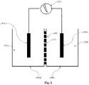
- the Figure 1 schematically represents an example of an electrical energy production device according to the present invention, comprising two tanks 20A and 20B, respectively tank A and tank B, separated by a membrane 10.
- Each of the two tanks contains an electrolytic solution 22A and 22B of concentration respective C A and C B in the same solute, in which soaks an electrode 30A and 30B.
- the two electrodes 30A and 30B are connected to a device making it possible to capture then supply the electrical energy generated.
- Each reservoir A and B can be any device or natural environment, open or closed, capable of containing a liquid.
- the concentrations C A and C B in the same solute of the electrolytic solutions 22A and 22B are necessarily different.
- C B is less than C A , which leads to a circulation of solute ions from reservoir A to reservoir B.
- the membrane 10, called the “nano-fluidic” membrane, separating the two reservoirs A and B comprises at least one nano-channel 11 arranged to allow the diffusion of electrolytes from one reservoir to the other through the said nano-channel(s). .
- diffusion will take place from reservoir A to reservoir B.
- Said nano-channel(s) 11 have an average cross-section enabling both water molecules and solute ions to circulate.
- the morphology of these nano-channels promotes good diffusion of the solution through the membrane.
- at least part of the internal surface of the nano-channel(s) essentially consists of at least one titanium oxide (TiO 2 ).
- the electrodes 30A and 30B can be partially or entirely immersed in the solutions 22A and 22B. It is also possible to provide for the electrodes to take the form of at least part of a wall of the reservoirs.
- the device (32) makes it possible to capture then supply the electrical energy spontaneously generated by the potential differential existing between the two electrodes 30A and 30B. It can consist of simple cables connecting a battery, a bulb or any other form of electrical consumer.
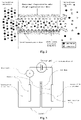
- the Figure 2 illustrates the phenomenon of diffusio-osmosis of an NaCl solution on the scale of a negatively charged nano-channel on the surface and generating an ionically unbalanced flux under the influence of the surface charge of the materials at the origin of the current electric.
- the Figure 3 illustrates the device of examples 1 and 2 making it possible to measure the electric current and the electric power generated per m 2 of a nanofluidic membrane comprising a nano-channel whose internal surface is made of TiO 2 .
- the electrical energy is generated thanks to the difference in the concentrations C A and C B in the same solute of the electrolytic solutions which causes the mobility of the electrolytes by diffusion-osmosis of the most concentrated solution towards the least concentrated solution, through the nano-channels of the membrane and under the influence of their surface properties.
- one of the key points of the present invention is based on the nature, morphology and density of the nano-channels in the membrane according to the invention, in particular of the internal wall of said nano-channels.
- the choice of the material constituting the inner wall of the nano-channels is crucial because, depending on the nature of the material and its surface charge in an aqueous medium, the energy generated will be more or less significant.
- the electrolytic solution moving from one reservoir to another will be more or less electrically charged, since ionically unbalanced under the influence of the surface charge of the material.
- the more the electrolytic solution moving from one reservoir to the other is ionically unbalanced and the greater the difference in concentration between the two reservoirs, the greater the energy production.
- the inventors have discovered that the nano-channels, the internal wall of which consists essentially of titanium oxide, generate a very strong ionic imbalance in the electrolytic solution circulating between the two reservoirs, and therefore generates an energy particularly high electrical voltage between the two electrodes.
- titanium oxide is meant any type of metallic titanium oxide, namely titanium (II) oxide of formula TiO as well as the corresponding non-stechiometric forms of compositions between TiO 0.7 and TiO 1.3 , titanium (IV) oxide or titanium dioxide, as well as mixtures thereof. These titanium oxides can be in different solid forms polymorphs, in particular in amorphous form or else in crystalline form. In the case of titanium dioxide (TiO 2 ), the crystalline form of the rutile or anatase type will mainly be used, the anatase form however being preferred.
- the internal surface of the nano-channels can comprise one or more section(s) essentially consisting of an oxide of titanium or that the entire internal surface consists essentially of at least one titanium oxide.
- Said section(s) may be regular or irregular, intermittent or non-intermittent and/or in the form of one layer or multiple layers.
- the total internal surface of the nano-channels consists essentially of at least one titanium oxide.
- titanium oxide essentially consisting of titanium oxide, is meant, within the meaning of the present invention, consisting of titanium oxide and minority element(s) such as impurities.
- the inventors are of the opinion that, given their nature, their size and their physico-chemical properties, in particular their surface charge density of the order of 0.1 to 1 C /cm 2 , the nano-channels of titanium oxide, in particular titanium oxide, promote the passage of ions of charges opposite to their surface charge by a nanofluidic phenomenon of diffusio-osmosis generated by the salinity gradient.
- the Figure 2 illustrates in longitudinal section, the diffusion-osmosis phenomenon on the scale of a nano-channel. In particular, it represents the differentiated movement of Na + cations and Cl - anions from a concentrated NaCl solution to a dilute NaCl solution at the negatively charged surface of a TiO 2 nano-channel.
- the membrane according to the invention will create a globally electrically charged ion flux since it is unbalanced between anions and cations under the effect of surface charges.
- At least part of the internal surface of the nano-channels consists essentially of a titanium oxide, in particular in the form of TiO 2 .
- the nano-channels consist entirely of titanium oxide.
- the physicochemical properties of titanium oxide can generally be modulated and amplified by doping or functionalization, that is to say by introducing, at the surface or in the heart of the titanium network, metallic chemical elements such as iron, silver, vanadium, gold, platinum, niobium, tungsten or non-metallic such as nitrogen, sulfur, carbon, hydrogen, boron, phosphorus or different compounds chemicals from the family of silanes, amines or other organics, preferably in small quantities, such as of the order of a few percent by mass.
- metallic chemical elements such as iron, silver, vanadium, gold, platinum, niobium, tungsten or non-metallic such as nitrogen, sulfur, carbon, hydrogen, boron, phosphorus or different compounds chemicals from the family of silanes, amines or other organics, preferably in small quantities, such as of the order of a few percent by mass.
- the titanium oxide is doped by introducing, at the surface or at the heart of its crystal lattice, metallic chemical elements such as iron, silver, vanadium, gold, platinum, niobium, tungsten, or non-metallic such as nitrogen, sulfur, carbon, hydrogen, boron, phosphorus, or different chemical compounds such as silanes or amines, preferably in an amount of between 0.5 and 10% by mass and more preferably between 1 and 5% by mass.
- metallic chemical elements such as iron, silver, vanadium, gold, platinum, niobium, tungsten, or non-metallic such as nitrogen, sulfur, carbon, hydrogen, boron, phosphorus, or different chemical compounds such as silanes or amines, preferably in an amount of between 0.5 and 10% by mass and more preferably between 1 and 5% by mass.
- the choice of the material constituting the internal wall of the nano-channels also influences the industrialization of the membranes according to the invention.
- the membranes comprising nano-channels based on titanium are relatively easy to produce and inexpensive, compared to the membranes of boron nitride or based on carbon, boron and nitrogen described in the prior art.
- a membrane comprising nano-channels whose internal surface consists essentially of titanium oxide can be obtained directly by anodizing a titanium sheet ( cf.
- Said membranes can also be supported by a nanoporous or pierced mechanical support on which the titanium is deposited.
- said membranes can be composed of a flexible polymer membrane on which is deposited a layer of TiO 2 .
- the morphology of the nano-channels also influences the yield of electrical energy generated. Indeed, the average section of the nano-channels as well as their specific and regular crossing morphology favor the good diffusion of the solution through the membrane.
- the membrane according to the invention is clearly distinguished from the semi-permeable or ion exchange membranes of the prior art, by its nano-channels potentially allowing both water molecules and ions to circulate, since each of the nano- channels has a section greater than the size of these molecules.
- the nano-channels have an average diameter of between 1 and 500 nm, in particular between 10 and 100 nm.
- mean diameter is meant, in the context of the present invention, the mean internal diameter of the nano-channel.
- the nano-channel can have a nanotubular morphology, asymmetrical of the conical type, in a neck, or with a perforated base.
- the average diameter corresponds to the internal diameter of the circular section.
- the nano-channel has an asymmetrical morphology of conical type, neck, or with perforated base, or has an oval or irregular section, the average diameter corresponds to the average of the smallest and of the largest internal diameter.
- the average diameter of the nano-channels is measured by means known to those skilled in the art.
- the average diameter can be measured by scanning electron microscopy or transmission electron microscopy.
- the nano-channels present on the membrane have homogeneous diameters.
- the average diameter will correspond to the average of the average diameters of all the nano-channels.
- the nano-channels have a nanotubular morphology, asymmetrical of the conical type, neck, or with perforated base, preferably said nano-channels have an asymmetrical morphology of the conical type.
- the nano-channels have an asymmetrical morphology of the conical type, in a neck, or with a perforated base, the thinnest diameter of the nano-channels is then oriented towards the side of the reservoir containing the solution with the least concentration of dissolved solutes, this is that is, in our case, to tank B.
- said nano-channels have a length to average diameter ratio of less than 1000, in particular less than 100.
- the length of the nano-channels is also measured by means known to those skilled in the art; for example, by scanning electron microscopy or transmission electron microscopy.
- the density of nano-channels per unit area of membrane is greater than 10 5 nano-channels per cm 2 of membrane, in particular greater than 10 8 nano-channels per cm 2 of membrane. membrane.
- the density of nano-channels per unit area of membrane is measured by means known to those skilled in the art, such as by scanning electron microscopy or scanning ion microscopy. The higher the density of nano-channels per unit area of membrane, the greater the yield of electrical energy generated per unit area of membrane.
- the reservoirs A and B of the device according to the invention each contain an electrolytic solution (22A and 22B) of respective concentration C A and C B in the same solute, C B being less than C A .
- the concentration gradient could also be obtained by temperature gradient between the two reservoirs by playing on the solubility of the salt as a function of the temperature.
- the concentration ratio Rc (Rc being equal to the ratio of the concentration of the most concentrated solution/the concentration of the least concentrated solution) may be between 1 and 10 9 .
- the concentration ratio C A /C B is greater than 1 and less than or equal to 10 9 , advantageously greater than 10 and less than or equal to 10 5 .
- Electrolyte solutions are aqueous solutions comprising electrolytes.
- the electrolytes may be of any chemical nature insofar as they dissolve in the solution in the form of charged ions.
- these ions will come from dissolved salts such as NaCl, KCL, CaCl 2 and MgCl 2 .
- the electrolyte solutions can be synthetic solutions; natural solutions, such as fresh water from lakes or rivers, underground water, brackish water, sea water; industrial produced water, petroleum produced water or biological solutions.
- said electrolytic solutions are aqueous solutions comprising a solute chosen from alkali halides or alkaline-earth halides, preferably chosen from NaCl, KCl, CaCl 2 and MgCl 2 , more preferably the solute is NaCl.
- the pH of the solutions is adjusted according to the isoelectric point of the internal surface of the nano-channels.
- the pH of the solutions can be adjusted to a value between (pH iso +1) and 14, more favorably between the values (pH iso +2) and 12.
- the pH of the solutions can be adjusted to a value between 0 and (pH iso -1) more favorably between 1 and (pH iso -2).
- pH iso means the pH of the isoelectric point of the material constituting the internal surface of the nano-channels.
- the iso pH is measured by methods known to those skilled in the art, in particular by the acid/base potentiometric titration method
- a pH gradient may also be established between the two reservoirs, the difference in pH between the two solutions will be greater than 1, preferably greater than 2.
- Each of the reservoirs A and B of the device according to the invention also comprises an electrode (30A and 30B) arranged so as to come into contact with the electrolytic solution (22A and 22B).
- Electrolytic solution 22A and 22B
- Different types of electrodes can be used for recovering the electric potential or current developed between the two reservoirs. All types of electrodes capable of collecting the flow of Na + or Cl - ions can be used, and preferably electrodes composed of silver and silver chloride (Ag/AgCl), carbon and platinum (C/Pt- ), Carbon (C-), Graphite or even Iron complexes of the [Fe(CN)6] 4- /[Fe(CN)6] 3- type.
- the electrodes can be partially or completely immersed in the electrolyte solutions. Provision could also be made for the electrodes to take the form of at least part of a wall of the reservoirs. These electrodes are connected together to a device (32) making it possible to capture then supply the electrical energy spontaneously generated by the potential differential existing between them. These electrodes can in particular be connected by simple cables connecting a battery, a bulb or any other form of electrical consumer.
- the device thus described makes it possible to harvest the electrical energy resulting from the charged ion flux crossing the nano-fluidic membrane.
- the device in a particular mode of the invention, provision could be made for the device to comprise N reservoirs (20) and N-1 membranes (10), N being an integer, in particular between 3 and 100, in particular between 3 and In this device, the reservoirs and the membranes are as defined above.
- the assembly will therefore consist of alternating reservoirs containing alternately a concentrated electrolytic solution and a less concentrated electrolytic solution, separated from each other by membranes.
- Example 1 Preparation of a device according to the invention comprising a nano-fluidic membrane based on amorphous titanium oxide - Measurement of the electric current obtained
- the nano-fluidic membrane based on amorphous titanium oxide was obtained at 130°C using the ALD (Atomic Layer deposition) method by depositing a thickness of 5 nm of TiO 2 : amorphous titanium oxide was thus deposited on a nanotubular support in nano-melamine comprising a nano-channel and consisting of 16 bi-layers of Al 2 O 3 and ZnO on SiN to obtain a good grip and a good surface condition previously perforated to the desired diameter of 110nm.
- ALD Atomic Layer deposition
- the membrane thus obtained comprises a nano-channel based on amorphous titanium oxide, with an internal diameter of 100 nanometers and a length of 200 nanometers.
- the isoelectric point of the membrane has been identified at a pH of the order of 6.5.
- This device consists of two independent reservoirs, each containing a solution of potassium chloride (KCl) dissolved at different concentrations between 1 mM and 1M, making it possible to define the concentration gradient Rc of 1, 10, 100 and 1000 between the two reservoirs.
- KCl potassium chloride
- the two reservoirs are separated by the nano-tubular membrane based on amorphous titanium oxide obtained in step 1.
- Ag/AgCl electrodes are used to measure the electric current produced through the titanium oxide nano-tubular membrane.
- an ammeter and a current generator making it possible to impose a potential difference are positioned in series between the two electrodes.
- the Figure 3 represents this device.
- Example 2 Preparation of a device according to the invention comprising a nano-fluidic membrane based on titanium oxide in anatase form - Measurement of the electric current obtained
- the nano-fluidic membrane based on amorphous titanium oxide was obtained at 130°C using the ALD (Atomic Layer deposition) method by depositing a thickness of 5 nm of TiO 2 : amorphous titanium oxide was thus deposited on a nanotubular support in nano-melamine comprising a nano-channel and consisting of 16 bi-layers of Al 2 O 3 and ZnO on SiN to obtain a good grip and a good surface condition previously perforated to the desired diameter of 110nm.
- ALD Atomic Layer deposition
- the membrane thus obtained was annealed at 500° C. for 2 hours in air to crystallize the titanium oxide in its anatase form.
- This membrane then comprises a nano-channel based on titanium oxide in anatase form of nanotubular morphology, with an internal diameter of 100 nanometers and a length of 200 nanometers.
- the isoelectric point of the membrane has been identified at a pH of the order of 4.
- the device used is in all respects similar to the device of Example 1 using the nano-fluidic membrane based on titanium oxide in anatase form.
- Pmax I osm 2 /4G.
- the maximum powers of energy produced per m 2 for each concentration gradient and pH are shown in Table 6.
- the powers measured are again clearly superior to the state of the art to reach values exceeding 5 kW/m 2 .
Landscapes
- Chemical & Material Sciences (AREA)
- Engineering & Computer Science (AREA)
- Chemical Kinetics & Catalysis (AREA)
- Water Supply & Treatment (AREA)
- Combustion & Propulsion (AREA)
- Inorganic Chemistry (AREA)
- Manufacturing & Machinery (AREA)
- Analytical Chemistry (AREA)
- General Engineering & Computer Science (AREA)
- Mechanical Engineering (AREA)
- Physics & Mathematics (AREA)
- Optics & Photonics (AREA)
- Electrochemistry (AREA)
- General Chemical & Material Sciences (AREA)
- Sustainable Energy (AREA)
- Sustainable Development (AREA)
- Life Sciences & Earth Sciences (AREA)
- Separation Using Semi-Permeable Membranes (AREA)
- Inorganic Compounds Of Heavy Metals (AREA)
- Conductive Materials (AREA)
- Hybrid Cells (AREA)
- Physical Or Chemical Processes And Apparatus (AREA)
Description
L'invention a pour objet un dispositif pour la production d'énergie électrique par gradient de salinité à travers une membrane nano-fluidique à base d'oxyde de titane. L'invention a également pour objet un procédé de production d'énergie utilisant un tel dispositif.The subject of the invention is a device for the production of electrical energy by salinity gradient through a nano-fluidic membrane based on titanium oxide. The invention also relates to a method for producing energy using such a device.
La production d'énergie par gradient de salinité est une des sources d'énergie renouvelable présentant le plus gros potentiel à l'échelle de la planète.Salinity gradient energy production is one of the renewable energy sources with the greatest potential on a planetary scale.
Quatre technologies distinctes sont actuellement envisagées pour récolter cette énergie « bleue » : la voie par pression osmotique retardée (PRO - Pressure Retarded Osmosis), la méthode d'électrodialyse inverse (RED- Reverse Electrodialysis), la technologie par systèmes capacitifs (Capmix) et la voie par membranes nanoporeuses de nitrure de bore.Four distinct technologies are currently envisaged to harvest this "blue" energy: the way by delayed osmotic pressure (PRO - Pressure Retarded Osmosis), the reverse electrodialysis method (RED- Reverse Electrodialysis), the technology by capacitive systems (Capmix) and the way by nanoporous membranes of boron nitride.
La voie par pression osmotique retardée (PRO), telle que décrite dans les brevets
Les membranes utilisées pour la PRO sont des membranes spécifiques dites semi-perméables. Ces membranes ne laissent passer que les molécules d'eau sans faire passer les ions provenant des sels dissous. Pour permettre cette sélectivité elles ont nécessairement une porosité maîtrisée avec des diamètres de pores de l'ordre de quelques angströms et sont généralement des membranes organiques à base de dérivés polyamides ou d'acétate de cellulose. Malgré de très nombreux travaux et de nombreuses recherches sur l'optimisation de ces membranes dédiées à la PRO, leur faible perméabilité, leur sensibilité à l'encrassement et les pertes énergétiques liées à la mise en oeuvre mécanique des turbines limitent la production d'énergie à quelques watts par m2 de membrane. Actuellement, le coût de ces membranes ramené à la quantité d'énergie produite ralentie le développement de cette technologie.The membranes used for the PRO are specific so-called semi-permeable membranes. These membranes only allow water molecules to pass without passing ions from dissolved salts. To allow this selectivity, they necessarily have a controlled porosity with pore diameters of the order of a few angstroms and are generally organic membranes based on polyamide derivatives or cellulose acetate. Despite a great deal of work and research on the optimization of these membranes dedicated to PRO, their low permeability, their sensitivity to fouling and the energy losses linked to the mechanical implementation of the turbines limit the production of energy. to a few watts per m 2 of membrane. Currently, the cost of these membranes reduced to the quantity of energy produced slows down the development of this technology.
L'électrodialyse inverse est une voie électrochimique basée sur le potentiel de Donnan à travers des membranes échangeuses d'ions dites « permsélectives ». Le dispositif est constitué d'une alternance de cellules dans lesquelles circulent la solution la plus concentrée en électrolyte et la solution la moins concentrée. Ces cellules sont séparées alternativement par des membranes échangeuses d'anions et des membranes échangeuses de cations. Aux extrémités de ces empilements de cellules sont positionnées des électrodes qui viennent récolter le courant électrique généré par le flux ionique global. Cependant, l'encrassement des membranes, l'accumulation de charges à la surface de ces membranes, leur faible perméabilité ainsi que la nécessité de les régénérer pénalisent le bilan économique global de cette technologie. La production d'énergie ramenée à la surface de membrane n'excède pas les quelques watts par m2.Reverse electrodialysis is an electrochemical pathway based on the Donnan potential through so-called "permselective" ion exchange membranes. The device consists of an alternation of cells in which the most concentrated electrolyte solution and the least concentrated solution circulate. These cells are alternately separated by anion exchange membranes and cation exchange membranes. At the ends of these stacks of cells are positioned electrodes which collect the electric current generated by the overall ion flux. However, the fouling of the membranes, the accumulation of charges on the surface of these membranes, their low permeability as well as the need to regenerate them penalize the overall economic balance of this technology. The production of energy brought back to the surface of the membrane does not exceed a few watts per m 2 .
Une seconde voie électrochimique, basée sur l'alternance de charges et de décharge de systèmes capacitifs (système Capmix) est également étudiée. Il semble que l'optimisation des membranes capacitives reste toujours un point délicat pour cette voie électrochimique.A second electrochemical way, based on the alternation of charges and discharge of capacitive systems (Capmix system) is also studied. It seems that the optimization of the capacitive membranes always remains a delicate point for this electrochemical way.
Récemment, une nouvelle voie sur la production d'énergie par gradient de salinité mettant en oeuvre des membranes nanoporeuses, à base de composés du type nitrure de bore ou plus généralement des composés à base de carbone, de bore et d'azote, a été découverte par
Il existe donc, au regard de ce qui précède, un besoin pour un procédé de production d'énergie électrique non polluant, facile à mettre en oeuvre, relativement économique et qui permet d'obtenir une production d'énergie par mètre carré de membrane qui soit de l'ordre du kW/m2. Notamment, il existe un besoin pour un dispositif permettant de produire de l'énergie électrique par gradient de salinité qui ne présente pas les inconvénients, défauts, limitations et désavantages des procédé de production d'énergie électrique par gradient de salinité de l'art antérieur, notamment en ce qui concerne l'industrialisation et le coût de production de ces membranes.There is therefore, in the light of the foregoing, a need for a process for the production of electrical energy which is non-polluting, easy to implement, relatively economical and which makes it possible to obtain an energy production per square meter of membrane which or of the order of kW/m 2 . In particular, there is a need for a device making it possible to produce energy electricity by salinity gradient which does not have the drawbacks, defects, limitations and disadvantages of the methods for the production of electric energy by salinity gradient of the prior art, in particular as regards the industrialization and the cost of production of these membranes.
La présente invention se propose d'apporter une solution efficace pour produire de l'énergie électrique par gradient de salinité en termes de puissance énergétique produite et de coût de production des membranes.The present invention proposes to provide an effective solution for producing electrical energy by salinity gradient in terms of the energy power produced and the cost of producing the membranes.
Dans le cadre de la présente invention, les inventeurs ont découvert que l'utilisation d'une membrane comprenant des nano-canaux dont au moins une partie de leur surface interne est essentiellement constituée d'au moins un oxyde de titane, dans un dispositif de production d'énergie par gradient de salinité, permet d'obtenir une production d'énergie par mètre carré de membrane qui soit de l'ordre du kW/m2, tout en réduisant le coût de production des membranes. En outre, l'utilisation de telles membranes permet également de faciliter le développement à plus grande échelle d'un dispositif de production d'énergie par gradient de salinité et d'en réduire le coût.In the context of the present invention, the inventors have discovered that the use of a membrane comprising nano-channels of which at least a part of their internal surface is essentially made up of at least one titanium oxide, in a device for production of energy by salinity gradient, makes it possible to obtain an energy production per square meter of membrane which is of the order of kW/m 2 , while reducing the cost of production of the membranes. In addition, the use of such membranes also makes it possible to facilitate the development on a larger scale of a device for producing energy by salinity gradient and to reduce the cost thereof.
Dans un premier aspect, la présente invention concerne donc un dispositif pour la production d'énergie électrique comprenant :
- a. un premier réservoir A (20A) destiné à recevoir une solution électrolytique de concentration CA en un soluté (22A) et comprenant une électrode (30A) disposée de manière à entrer en contact avec la solution électrolytique de concentration CA;
- b. un deuxième réservoir B (20B) destiné à recevoir une solution électrolytique de concentration CB en un même soluté (22B), CB étant inférieure à CA, et comprenant une électrode (30B) disposée de manière à entrer en contact avec la solution électrolytique de concentration CB ;
- c. une membrane (10) séparant les deux réservoirs, ladite membrane comprenant au moins un nano-canal (11) agencé pour permettre la diffusion des électrolytes du réservoir A vers le réservoir B à travers le ou lesdits nano-canaux ; et
- has. a first reservoir A (20A) intended to receive an electrolyte solution of concentration C A in a solute (22A) and comprising an electrode (30A) arranged so as to come into contact with the electrolyte solution of concentration C A ;
- b. a second tank B (20B) intended to receive an electrolytic solution of concentration C B in the same solute (22B), C B being lower than C A , and comprising an electrode (30B) arranged so as to come into contact with the solution electrolytic concentration C B ;
- vs. a membrane (10) separating the two reservoirs, said membrane comprising at least one nano-channel (11) arranged to allow the diffusion of electrolytes from reservoir A to reservoir B through said nano-channel or channels; and
L'invention concerne en outre un procédé de production d'énergie électrique utilisant un dispositif tel que décrit ci-dessus, comprenant les étapes suivantes :
- i. fourniture d'un dispositif pour la production d'énergie électrique en suivant les étapes suivantes :
- placer ladite solution électrolytique de concentration CA en soluté (22A) dans le réservoir A (20A), de manière à ce que l'électrode (30A) dont il est équipé soit en contact avec ladite solution (22A),
- placer ladite solution électrolytique de concentration CB en un même soluté (22B), CB étant inférieure à CA, dans le réservoir B (20B), de manière à ce que l'électrode (30B) dont il est équipé soit en contact avec ladite solution (22B), et
- séparer les deux réservoirs A et B par ladite membrane (10) comprenant au moins un nano-canal (11) agencé pour permettre la diffusion des électrolytes du réservoir A vers le réservoir B à travers le ou lesdits nano-canaux ;
- ii. capter l'énergie électrique générée par le différentiel de potentiel existant entre les deux électrodes, à l'aide du dispositif (32).
- i. supply of a device for the production of electrical energy by following the following steps:
- placing said electrolytic solution of concentration C A in solute (22A) in tank A (20A), so that the electrode (30A) with which it is equipped is in contact with said solution (22A),
- placing said electrolyte solution of concentration C B in the same solute (22B), C B being less than C A , in reservoir B (20B), so that the electrode (30B) with which it is fitted is in contact with said solution (22B), and
- separating the two reservoirs A and B by said membrane (10) comprising at least one nano-channel (11) arranged to allow the diffusion of electrolytes from reservoir A to reservoir B through said nano-channel or channels;
- ii. capturing the electrical energy generated by the potential differential existing between the two electrodes, using the device (32).
La
Chaque réservoir A et B peut être tout dispositif ou environnement naturel, ouvert ou fermé, pouvant contenir un liquide.Each reservoir A and B can be any device or natural environment, open or closed, capable of containing a liquid.
Afin de générer un flux par diffusio-osmose, les concentrations CA et CB en un même soluté des solutions électrolytiques 22A et 22B sont nécessairement différentes. Dans le cadre de la présente invention, on considèrera arbitrairement que CB est inférieure à CA, ce qui entraine une circulation des ions du soluté du réservoir A vers le réservoir B.In order to generate a flux by diffusio-osmosis, the concentrations C A and C B in the same solute of the
La membrane 10, dite membrane « nano-fluidique », séparant les deux réservoirs A et B comprend au moins un nano-canal 11 agencé pour permettre la diffusion des électrolytes d'un réservoir à l'autre à travers le ou lesdits nano-canaux. Dans le cadre de la présente invention, la diffusion se fera du réservoir A au réservoir B. Le ou lesdits nano-canaux 11 ont une section moyenne permettant de laisser circuler tant les molécules d'eau que les ions du soluté. En outre, la morphologie de ces nano-canaux favorise une bonne diffusion de la solution à travers la membrane. Dans le cadre de la présente invention, au moins une partie de la surface interne du ou des nano-canaux est essentiellement constituée d'au moins un oxyde de titane (TiO2).The
Les électrodes 30A et 30B peuvent être partiellement ou entièrement plongées dans les solutions 22A et 22B. Il est également possible de prévoir que les électrodes se présentent sous la forme d'au moins une partie d'une paroi des réservoirs.The
Le dispositif (32) permet de capter puis fournir l'énergie électrique spontanément générée par le différentiel de potentiel existant entre les deux électrodes 30A et 30B. Il peut être constitué de simples câbles reliant une batterie, une ampoule ou toute autre forme de consommateur électrique.The device (32) makes it possible to capture then supply the electrical energy spontaneously generated by the potential differential existing between the two
La
La
La présente invention concerne un dispositif de production d'énergie électrique par gradient de salinité comprenant :
- a. un premier réservoir A (20A) destiné à recevoir une solution électrolytique de concentration CA en un soluté (22A) et comprenant une électrode (30A) disposée de manière à entrer en contact avec la solution électrolytique de concentration CA;
- b. un deuxième réservoir B (20B) destiné à recevoir une solution électrolytique de concentration CB en un même soluté (22B), CB étant inférieure à CA, et comprenant une électrode (30B) disposée de manière à entrer en contact avec la solution électrolytique de concentration CB ;
- c. une membrane (10) séparant les deux réservoirs, ladite membrane comprenant au moins un nano-canal (11) agencé pour permettre la diffusion des électrolytes du réservoir A vers le réservoir B à travers le ou lesdits nano-canaux ; et
- d. un dispositif (32) permettant de fournir l'énergie électrique générée par le différentiel de potentiel existant entre les deux électrodes, caractérisé en ce qu'au moins une partie de la surface interne du ou des nano-canaux est essentiellement constituée d'au moins un oxyde de titane.
- has. a first reservoir A (20A) intended to receive an electrolyte solution of concentration C A in a solute (22A) and comprising an electrode (30A) arranged so as to come into contact with the electrolyte solution of concentration C A ;
- b. a second tank B (20B) intended to receive an electrolytic solution of concentration C B in the same solute (22B), C B being lower than C A , and comprising an electrode (30B) arranged so as to come into contact with the solution electrolytic concentration C B ;
- vs. a membrane (10) separating the two reservoirs, said membrane comprising at least one nano-channel (11) arranged to allow the diffusion of electrolytes from reservoir A to reservoir B through said nano-channel or channels; and
- d. a device (32) making it possible to supply the electrical energy generated by the potential differential existing between the two electrodes, characterized in that at least a part of the internal surface of the nano-channel(s) essentially consists of at least a titanium oxide.
Ce dispositif est décrit de manière plus détaillée ci-dessous et dans la description de la
Dans le dispositif selon l'invention, l'énergie électrique est générée grâce à la différence des concentrations CA et CB en un même soluté des solutions électrolytiques qui provoque la mobilité des électrolytes par diffusio-osmose de la solution la plus concentrée vers la solution la moins concentrée, à travers les nano-canaux de la membrane et sous l'influence de leurs propriétés de surface.In the device according to the invention, the electrical energy is generated thanks to the difference in the concentrations C A and C B in the same solute of the electrolytic solutions which causes the mobility of the electrolytes by diffusion-osmosis of the most concentrated solution towards the least concentrated solution, through the nano-channels of the membrane and under the influence of their surface properties.
Ainsi, un des points clés de la présente invention repose sur la nature, la morphologie et la densité des nano-canaux dans la membrane selon l'invention, notamment de la paroi interne desdits nano-canaux.Thus, one of the key points of the present invention is based on the nature, morphology and density of the nano-channels in the membrane according to the invention, in particular of the internal wall of said nano-channels.
D'une part, le choix du matériau constituant la paroi interne des nano-canaux est crucial car, selon la nature du matériau et sa charge de surface en milieu aqueux, l'énergie générée sera plus ou moins importante. En effet, selon la nature du matériau de la paroi interne des nano-canaux, la solution électrolytique se déplaçant d'un réservoir à l'autre sera plus ou moins chargée électriquement, puisque déséquilibrée ioniquement sous l'influence de la charge de surface du matériau. Or, plus la solution électrolytique se déplaçant d'un réservoir à l'autre est déséquilibrée ioniquement et plus la différence de concentration est élevée entre les deux réservoirs, plus la production d'énergie est importante.On the one hand, the choice of the material constituting the inner wall of the nano-channels is crucial because, depending on the nature of the material and its surface charge in an aqueous medium, the energy generated will be more or less significant. Indeed, depending on the nature of the material of the inner wall of the nano-channels, the electrolytic solution moving from one reservoir to another will be more or less electrically charged, since ionically unbalanced under the influence of the surface charge of the material. However, the more the electrolytic solution moving from one reservoir to the other is ionically unbalanced and the greater the difference in concentration between the two reservoirs, the greater the energy production.
Dans le cadre de la présente invention, les inventeurs ont découvert que les nano-canaux dont la paroi interne est essentiellement constituée d'oxyde de titane engendrent un très fort déséquilibre ionique de la solution électrolytique circulant entre les deux réservoirs, et génère donc une énergie électrique particulièrement élevée entre les deux électrodes.In the context of the present invention, the inventors have discovered that the nano-channels, the internal wall of which consists essentially of titanium oxide, generate a very strong ionic imbalance in the electrolytic solution circulating between the two reservoirs, and therefore generates an energy particularly high electrical voltage between the two electrodes.
Par oxyde de titane, on entend tout type d'oxyde de titane métallique, à savoir l'oxyde de titane (II) de formule TiO ainsi que les formes non stechiométriques correspondantes de compositions comprises entre TiO0,7 et TiO1,3, l'oxyde de titane (IV) ou dioxyde de titane, ainsi que leurs mélanges. Ces oxydes de titane peuvent se présenter sous différentes formes solides polymorphes, notamment sous forme amorphe ou encore sous forme cristalline. Dans le cas du dioxyde de titane (TiO2) on utilisera principalement la forme cristalline de type rutile ou anatase, la forme anatase étant toutefois préférée.By titanium oxide is meant any type of metallic titanium oxide, namely titanium (II) oxide of formula TiO as well as the corresponding non-stechiometric forms of compositions between TiO 0.7 and TiO 1.3 , titanium (IV) oxide or titanium dioxide, as well as mixtures thereof. These titanium oxides can be in different solid forms polymorphs, in particular in amorphous form or else in crystalline form. In the case of titanium dioxide (TiO 2 ), the crystalline form of the rutile or anatase type will mainly be used, the anatase form however being preferred.
Par au moins une partie de la surface interne des nano-canaux, on entend, au sens de la présente invention, que la surface interne des nano-canaux peut comprendre une ou plusieurs section(s) essentiellement constituée(s) d'un oxyde de titane ou que la totalité de la surface interne est essentiellement constituée d'au moins un oxyde de titane. Ladite ou lesdites sections peuvent être régulières ou irrégulières, intermittentes ou non-intermittentes et/ou sous forme d'une couche ou de multi-couches. De préférence, la surface interne totale des nano-canaux est essentiellement constituée d'au moins un oxyde de titane.By at least part of the internal surface of the nano-channels, it is meant, within the meaning of the present invention, that the internal surface of the nano-channels can comprise one or more section(s) essentially consisting of an oxide of titanium or that the entire internal surface consists essentially of at least one titanium oxide. Said section(s) may be regular or irregular, intermittent or non-intermittent and/or in the form of one layer or multiple layers. Preferably, the total internal surface of the nano-channels consists essentially of at least one titanium oxide.
Par « essentiellement constituée d'oxyde de titane », on entend, au sens de la présente invention, constituée d'oxyde de titane et d'élément(s) minoritaire(s) tels que des impuretés.By “essentially consisting of titanium oxide”, is meant, within the meaning of the present invention, consisting of titanium oxide and minority element(s) such as impurities.
Sans vouloir se lier à une quelconque théorie, les inventeurs sont d'avis que compte tenu de leur nature, leur dimension et de leurs propriétés physico-chimiques, notamment leur densité de charge de surface de l'ordre de 0,1 à 1 C/cm2, les nano-canaux d'oxyde de titane, notamment d'oxyde de titane, favorisent le passage des ions de charges opposées à leur charge de surface par un phénomène nanofluidique de diffusio-osmose généré par le gradient de salinité. La
Dans un mode de réalisation préféré, au moins une partie de la surface interne des nano-canaux est essentiellement constituée d'un oxyde de titane, en particulier sous forme de TiO2.In a preferred embodiment, at least part of the internal surface of the nano-channels consists essentially of a titanium oxide, in particular in the form of TiO 2 .
Avantageusement, les nano-canaux sont entièrement constitué d'oxyde de titane,.Advantageously, the nano-channels consist entirely of titanium oxide.
Les propriétés physico-chimiques de l'oxyde detitane, peuvent généralement être modulées et amplifiées par dopage ou fonctionnalisation, c'est-à-dire par introduction, en surface ou au coeur du réseau du titane, d'éléments chimiques métalliques tels que le fer, l'argent, le vanadium, l'or, le platine, le niobium, le tungstène ou non métalliques tels que l'azote, le souffre, le carbone, l'hydrogène, le bore, le phosphore ou de différents composés chimiques de la famille des silanes, amines ou autres organiques, de préférence en faibles quantités, telles que de l'ordre de quelques pourcents en masse.The physicochemical properties of titanium oxide can generally be modulated and amplified by doping or functionalization, that is to say by introducing, at the surface or in the heart of the titanium network, metallic chemical elements such as iron, silver, vanadium, gold, platinum, niobium, tungsten or non-metallic such as nitrogen, sulfur, carbon, hydrogen, boron, phosphorus or different compounds chemicals from the family of silanes, amines or other organics, preferably in small quantities, such as of the order of a few percent by mass.
Dans un mode de réalisation préféré de l'invention, l'oxyde de titane est dopé par introduction, en surface ou au coeur de son réseau cristallin, d'éléments chimiques métalliques tels que le fer, l'argent, le vanadium, l'or, le platine, le niobium, le tungstène, ou non métalliques tels que l'azote, le souffre, le carbone, l'hydrogène, le bore, le phosphore, ou de différents composés chimiques tels que les silanes ou aminés, de préférence en une quantité comprise entre 0,5 et 10% en masse et plus préférentiellement entre 1 et 5% en masse.In a preferred embodiment of the invention, the titanium oxide is doped by introducing, at the surface or at the heart of its crystal lattice, metallic chemical elements such as iron, silver, vanadium, gold, platinum, niobium, tungsten, or non-metallic such as nitrogen, sulfur, carbon, hydrogen, boron, phosphorus, or different chemical compounds such as silanes or amines, preferably in an amount of between 0.5 and 10% by mass and more preferably between 1 and 5% by mass.
Le choix du matériau constituant la paroi interne des nano-canaux influence également l'industrialisation des membranes selon l'invention. En effet, les membranes comprenant des nano-canaux à base de titane, sont relativement aisées à produire et peu couteuse, comparativement aux membranes de nitrure de bore ou à base de carbone, de bore et d'azote décrites dans l'art antérieur. En effet, une membrane comprenant des nano-canaux dont la surface interne est constituée essentiellement d'oxyde de titane, peut être obtenue directement par anodisation d'une feuille de titane (cf.
Lesdites membranes peuvent également être supportées par un support mécanique nanoporeux ou percé sur lequel le titane est déposé. Par exemple, lesdites membranes peuvent être composées d'une membrane polymère souple sur laquelle est déposée une couche de TiO2.Said membranes can also be supported by a nanoporous or pierced mechanical support on which the titanium is deposited. For example, said membranes can be composed of a flexible polymer membrane on which is deposited a layer of TiO 2 .
D'autre part, la morphologie des nano-canaux influence également le rendement en énergie électrique générée. En effet, la section moyenne des nano-canaux ainsi que leur morphologie traversante spécifique et régulière favorisent la bonne diffusion de la solution à travers la membrane. Ainsi, la membrane selon l'invention se distingue nettement des membranes semi-perméables ou échangeuses d'ions de l'art antérieure, par ses nano-canaux laissant potentiellement circuler tant les molécules d'eaux que les ions, puisque chacun des nano-canaux possède une section supérieure à la taille de ces molécules.On the other hand, the morphology of the nano-channels also influences the yield of electrical energy generated. Indeed, the average section of the nano-channels as well as their specific and regular crossing morphology favor the good diffusion of the solution through the membrane. Thus, the membrane according to the invention is clearly distinguished from the semi-permeable or ion exchange membranes of the prior art, by its nano-channels potentially allowing both water molecules and ions to circulate, since each of the nano- channels has a section greater than the size of these molecules.
Dans le cadre de la présente invention, les nano-canaux ont un diamètre moyen compris entre 1 et 500 nm, en particulier entre 10 et 100 nm.In the context of the present invention, the nano-channels have an average diameter of between 1 and 500 nm, in particular between 10 and 100 nm.
Par « diamètre moyen » on entend, dans le cadre de la présente invention, le diamètre moyen interne du nano-canal. Le nano-canal peut avoir une morphologie nanotubulaire, asymétrique de type conique, en goulot, ou avec culot perforé. Lorsque le nano-canal a une morphologie nanotubulaire, c'est-à-dire avec une section circulaire, le diamètre moyen correspond au diamètre interne de la section circulaire. Lorsque le nano-canal a une morphologie asymétrique de type conique, en goulot, ou avec culot perforé, ou a une section ovale ou irrégulière, le diamètre moyen correspond à la moyenne du plus petit et du plus grand diamètre interne. Le diamètre moyen des nano-canaux se mesure par des moyens connus de l'homme du métier. Par exemple, le diamètre moyen peut être mesuré par microscopie électronique à balayage ou microscopie électronique à transmission. De manière avantageuse, les nano-canaux présents sur la membrane présentent des diamètres homogènes. Lorsque, sur une même membrane, les nano-canaux ne présentent pas tous des diamètres homogènes, le diamètre moyen correspondra à la moyenne des diamètres moyens de l'ensemble des nano-canaux.By “mean diameter” is meant, in the context of the present invention, the mean internal diameter of the nano-channel. The nano-channel can have a nanotubular morphology, asymmetrical of the conical type, in a neck, or with a perforated base. When the nano-channel has a nanotubular morphology, that is to say with a circular section, the average diameter corresponds to the internal diameter of the circular section. When the nano-channel has an asymmetrical morphology of conical type, neck, or with perforated base, or has an oval or irregular section, the average diameter corresponds to the average of the smallest and of the largest internal diameter. The average diameter of the nano-channels is measured by means known to those skilled in the art. For example, the average diameter can be measured by scanning electron microscopy or transmission electron microscopy. Advantageously, the nano-channels present on the membrane have homogeneous diameters. When, on the same membrane, the nano-channels do not all have uniform diameters, the average diameter will correspond to the average of the average diameters of all the nano-channels.
Avantageusement, dans le cadre de la présente invention, les nano-canaux ont une morphologie nanotubulaire, asymétrique de type conique, en goulot, ou avec culot perforé, de préférence les dits nano-canaux ont une morphologie asymétrique de type conique. Lorsque les nano-canaux ont une morphologie asymétrique de type conique, en goulot, ou avec culot perforé, le diamètre le plus fin des nano-canaux est alors orienté du côté du réservoir contenant la solution la moins concentrée en solutés dissous, c'est-à-dire, dans notre cas, vers le réservoir B.Advantageously, in the context of the present invention, the nano-channels have a nanotubular morphology, asymmetrical of the conical type, neck, or with perforated base, preferably said nano-channels have an asymmetrical morphology of the conical type. When the nano-channels have an asymmetrical morphology of the conical type, in a neck, or with a perforated base, the thinnest diameter of the nano-channels is then oriented towards the side of the reservoir containing the solution with the least concentration of dissolved solutes, this is that is, in our case, to tank B.
De manière préférée, lesdits nano-canaux présentent un rapport longueur sur diamètre moyen inférieur à 1000, en particulier inférieur à 100. La longueur des nano-canaux se mesure également par des moyens connus de l'homme du métier ; par exemple, par microscopie électronique à balayage ou microscopie électronique à transmission.Preferably, said nano-channels have a length to average diameter ratio of less than 1000, in particular less than 100. The length of the nano-channels is also measured by means known to those skilled in the art; for example, by scanning electron microscopy or transmission electron microscopy.
Dans un mode de réalisation préféré de l'invention, la densité de nano-canaux par unité de surface de membrane est supérieure à 105 nano-canaux par cm2 de membrane, en particulier supérieure à 108 nano-canaux par cm2 de membrane. La densité de nano-canaux par unité de surface de membrane se mesure par des moyens connus de l'homme du métier, tels que par microscopie électronique à balayage ou microscopie ionique à balayage. Plus la densité de nano-canaux par unité de surface de membrane est élevée, plus le rendement en énergie électrique générée par unité de surface de membrane est importantIn a preferred embodiment of the invention, the density of nano-channels per unit area of membrane is greater than 10 5 nano-channels per cm 2 of membrane, in particular greater than 10 8 nano-channels per cm 2 of membrane. membrane. The density of nano-channels per unit area of membrane is measured by means known to those skilled in the art, such as by scanning electron microscopy or scanning ion microscopy. The higher the density of nano-channels per unit area of membrane, the greater the yield of electrical energy generated per unit area of membrane.
Dans un mode de réalisation particulier, les réservoirs A et B du dispositif selon l'invention contiennent chacun une solution électrolytique (22A et 22B) de concentration respective CA et CB en un même soluté, CB étant inférieure à CA.In a particular embodiment, the reservoirs A and B of the device according to the invention each contain an electrolytic solution (22A and 22B) of respective concentration C A and C B in the same solute, C B being less than C A .
En disposant dans les deux réservoirs A et B des solutions électrolytiques de concentrations différentes, un flux osmotique est généré entre les deux réservoirs par diffusio-osmose, sans qu'aucune pression osmotique n'apparaisse. Dans un autre mode de réalisation, le gradient de concentration pourrait également être obtenu par gradient de température entre les deux réservoirs en jouant sur la solubilité du sel en fonction de la température.By placing electrolytic solutions of different concentrations in the two tanks A and B, an osmotic flow is generated between the two tanks by diffusio-osmosis, without any osmotic pressure appearing. In another embodiment, the concentration gradient could also be obtained by temperature gradient between the two reservoirs by playing on the solubility of the salt as a function of the temperature.
Dans le cadre de la présente invention, le ratio de concentration Rc (Rc étant égal au rapport de la concentration de la solution la plus concentrée/la concentration de la solution la moins concentrée) pourra être compris entre 1 et 109. De préférence, le ratio de concentration CA/CB est supérieur à 1 et inférieur ou égal à 109, avantageusement supérieur à 10 et inférieur ou égal à 105.In the context of the present invention, the concentration ratio Rc (Rc being equal to the ratio of the concentration of the most concentrated solution/the concentration of the least concentrated solution) may be between 1 and 10 9 . Preferably, the concentration ratio C A /C B is greater than 1 and less than or equal to 10 9 , advantageously greater than 10 and less than or equal to 10 5 .
Les solutions électrolytiques sont des solutions aqueuses comprenant des électrolytes. Les électrolytes pourront être de toute nature chimique dans la mesure où ils se dissolvent dans la solution sous forme d'ions chargés. Préférentiellement, ces ions proviendront de sels dissous tels que NaCl, KCL, CaCl2 et MgCl2. Les solutions électrolytiques peuvent être des solutions synthétiques ; des solutions naturelles, telles que des eaux douces provenant des lacs ou des rivières, des eaux sous-terraines, des eaux saumâtres, de l'eau de mer ; des eaux de production industrielle, des eaux de production pétrolière ou des solutions biologiques.Electrolyte solutions are aqueous solutions comprising electrolytes. The electrolytes may be of any chemical nature insofar as they dissolve in the solution in the form of charged ions. Preferably, these ions will come from dissolved salts such as NaCl, KCL, CaCl 2 and MgCl 2 . The electrolyte solutions can be synthetic solutions; natural solutions, such as fresh water from lakes or rivers, underground water, brackish water, sea water; industrial produced water, petroleum produced water or biological solutions.
De manière préférée, lesdites solutions électrolytiques sont des solutions aqueuses comprenant un soluté choisi parmi les halogénures alcalins ou les halogénures alcalino-terreux, de préférence choisi parmi NaCl, KCL, CaCl2 et MgCl2, de manière davantage préféré le soluté est le NaCl.Preferably, said electrolytic solutions are aqueous solutions comprising a solute chosen from alkali halides or alkaline-earth halides, preferably chosen from NaCl, KCl, CaCl 2 and MgCl 2 , more preferably the solute is NaCl.
Pour améliorer le flux osmotique généré de part et d'autre de la membrane de nano-canaux à base d'oxyde de titane, , le pH des solutions est ajusté en fonction du point isoélectrique de la surface interne des nano-canaux. Pour obtenir une charge négative en surface interne des nano-canaux, le pH des solutions pourra être ajusté à une valeur comprise entre (pHiso +1) et 14, plus favorablement entre les valeurs (pHiso+2) et 12. Pour obtenir une charge positive en surface interne des nano-canaux, le pH des solutions pourra être ajusté à une valeur comprise entre 0 et (pHiso-1) plus favorablement entre 1 et (pHiso-2).To improve the osmotic flow generated on either side of the membrane of nano-channels based on titanium oxide, the pH of the solutions is adjusted according to the isoelectric point of the internal surface of the nano-channels. To obtain a negative charge on the internal surface of the nano-channels, the pH of the solutions can be adjusted to a value between (pH iso +1) and 14, more favorably between the values (pH iso +2) and 12. To obtain a positive charge on the internal surface of the nano-channels, the pH of the solutions can be adjusted to a value between 0 and (pH iso -1) more favorably between 1 and (pH iso -2).
Dans le cadre de la présente invention, on entend par pHiso, le pH du point isoélectrique du matériau constituant la surface interne des nano-canaux. Le pHiso se mesure par des méthodes connues de l'homme du métier, notamment par la méthode de titration potentiométrique acide/baseIn the context of the present invention, pH iso means the pH of the isoelectric point of the material constituting the internal surface of the nano-channels. The iso pH is measured by methods known to those skilled in the art, in particular by the acid/base potentiometric titration method
Plus favorablement encore, pour accroître l'asymétrie du dispositif et amplifier la quantité d'énergie électrique produite par le dispositif, un gradient de pH pourra également être établi entre les deux réservoirs, la différence de pH entre les deux solutions sera supérieure à 1, préférentiellement supérieure à 2.Even more favorably, to increase the asymmetry of the device and amplify the amount of electrical energy produced by the device, a pH gradient may also be established between the two reservoirs, the difference in pH between the two solutions will be greater than 1, preferably greater than 2.
Chacun des réservoirs A et B du dispositif selon l'invention comprend également une électrode (30A et 30B) disposée de manière à entrer en contact avec la solution électrolytique (22A et 22B). Différents types d'électrodes pourront être utilisés pour la récupération du potentiel ou courant électrique développé entre les deux réservoirs. Tous types d'électrodes capables de collecter le flux de ion Na+ou Cl-pourront être utilisés, et de préférence les électrodes composés d'Argent et Chlorure d'Argent (Ag/AgCl), de Carbone et Platine (C/Pt-), de Carbone (C-), de Graphite ou encore de complexes de Fer du type [Fe(CN)6]4-/[Fe(CN)6]3-.Each of the reservoirs A and B of the device according to the invention also comprises an electrode (30A and 30B) arranged so as to come into contact with the electrolytic solution (22A and 22B). Different types of electrodes can be used for recovering the electric potential or current developed between the two reservoirs. All types of electrodes capable of collecting the flow of Na + or Cl - ions can be used, and preferably electrodes composed of silver and silver chloride (Ag/AgCl), carbon and platinum (C/Pt- ), Carbon (C-), Graphite or even Iron complexes of the [Fe(CN)6] 4- /[Fe(CN)6] 3- type.
Les électrodes peuvent être partiellement ou entièrement plongées dans les solutions électrolytiques. Il pourrait également être prévu que les électrodes se présentent sous la forme d'au moins une partie d'une paroi des réservoirs. Ces électrodes sont reliées ensemble à un dispositif (32) permettant de capter puis fournir l'énergie électrique spontanément générée par le différentiel de potentiel existant entre elles. Ces électrodes peuvent notamment être reliées par de simples câbles reliant une batterie, une ampoule ou toute autre forme de consommateur électrique.The electrodes can be partially or completely immersed in the electrolyte solutions. Provision could also be made for the electrodes to take the form of at least part of a wall of the reservoirs. These electrodes are connected together to a device (32) making it possible to capture then supply the electrical energy spontaneously generated by the potential differential existing between them. These electrodes can in particular be connected by simple cables connecting a battery, a bulb or any other form of electrical consumer.
Le dispositif ainsi décrit permet de récolter l'énergie électrique résultant du flux ionique chargé traversant la membrane nano-fluidique.The device thus described makes it possible to harvest the electrical energy resulting from the charged ion flux crossing the nano-fluidic membrane.
Dans un mode particulier de l'invention, il pourrait être prévu que le dispositif comprenne N réservoirs (20) et N-1 membranes (10), N étant un nombre entier, notamment compris entre 3 et 100, en particulier compris entre 3 et 50 Dans ce dispositif, les réservoirs et les membranes sont tels que définis ci-dessus. L'ensemble sera donc constitué d'une alternance de réservoirs contenant alternativement une solution électrolytique concentrée et une solution électrolytique moins concentrée, séparés entre eux par des membranes.In a particular mode of the invention, provision could be made for the device to comprise N reservoirs (20) and N-1 membranes (10), N being an integer, in particular between 3 and 100, in particular between 3 and In this device, the reservoirs and the membranes are as defined above. The assembly will therefore consist of alternating reservoirs containing alternately a concentrated electrolytic solution and a less concentrated electrolytic solution, separated from each other by membranes.
Dans un deuxième aspect, la présente invention concerne un procédé de production d'énergie électrique utilisant un dispositif tel que décrit ci-dessus, comprenant les étapes suivantes :
- i. fourniture d'un dispositif pour la production d'énergie électrique en suivant les étapes suivantes :
- placer ladite solution électrolytique de concentration CA en soluté (22A) dans le réservoir A (20A), de manière à ce que l'électrode (30A) dont il est équipé soit en contact avec ladite solution (22A),
- placer ladite solution électrolytique de concentration CB en un même soluté (22B), CB étant inférieure à CA, dans le réservoir B (20B), de manière à ce que l'électrode (30B) dont il est équipé soit en contact avec ladite solution (22B), et
- séparer les deux réservoirs A et B par ladite membrane (10) comprenant au moins un nano-canal (11) agencé pour permettre la diffusion des électrolytes du réservoir A vers le réservoir B à travers le ou lesdits nano-canaux ;
- ii. capter l'énergie électrique générée par le différentiel de potentiel existant entre les deux électrodes, à l'aide du dispositif (32).
- i. supply of a device for the production of electrical energy by following the following steps:
- placing said electrolytic solution of concentration C A in solute (22A) in tank A (20A), so that the electrode (30A) with which it is equipped is in contact with said solution (22A),
- placing said electrolyte solution of concentration C B in the same solute (22B), C B being less than C A , in reservoir B (20B), so that the electrode (30B) with which it is fitted is in contact with said solution (22B), and
- separating the two reservoirs A and B by said membrane (10) comprising at least one nano-channel (11) arranged to allow the diffusion of electrolytes from reservoir A to reservoir B through said nano-channel or channels;
- ii. capturing the electrical energy generated by the potential differential existing between the two electrodes, using the device (32).
Ces différentes étapes seront facilement réalisables par l'homme du métier, en utilisant ses connaissances générales.These different steps will be easily carried out by a person skilled in the art, using his general knowledge.
Les exemples qui suivent visent à illustrer la présente invention.The following examples are intended to illustrate the present invention.
La membrane nano-fluidique à base d'oxyde de titane amorphe a été obtenue à 130°C en utilisant la méthode ALD (Atomic Layer déposition) par dépôt d'une épaisseur de 5 nm de TiO2 : de l'oxyde de titane amorphe a été ainsi déposé sur un support nanotubulaire en nano-mélaminé comprenant un nano-canal et constitué de 16 bi-couches de Al2O3 et ZnO sur SiN pour obtenir une bonne accroche et un bon état de surface préalablement perforé au diamètre voulu de 110 nm .The nano-fluidic membrane based on amorphous titanium oxide was obtained at 130°C using the ALD (Atomic Layer deposition) method by depositing a thickness of 5 nm of TiO 2 : amorphous titanium oxide was thus deposited on a nanotubular support in nano-melamine comprising a nano-channel and consisting of 16 bi-layers of Al 2 O 3 and ZnO on SiN to obtain a good grip and a good surface condition previously perforated to the desired diameter of 110nm.
La membrane ainsi obtenue comprend un nano-canal à base d'oxyde de titane amorphe, avec un diamètre interne de 100 nanomètres et une longueur de 200 nanomètres.The membrane thus obtained comprises a nano-channel based on amorphous titanium oxide, with an internal diameter of 100 nanometers and a length of 200 nanometers.
Le point iso-électrique de la membrane a été identifié à un pH de l'ordre de 6,5.The isoelectric point of the membrane has been identified at a pH of the order of 6.5.
Ce dispositif est constitué de deux réservoirs indépendants contenant chacun une solution de chlorure de potassium (KCl) dissous à différentes concentrations comprises entre 1 mM et 1M permettant de définir le gradient de concentrations Rc de 1, 10, 100 et 1000 entre les deux réservoirs.This device consists of two independent reservoirs, each containing a solution of potassium chloride (KCl) dissolved at different concentrations between 1 mM and 1M, making it possible to define the concentration gradient Rc of 1, 10, 100 and 1000 between the two reservoirs.
Les deux réservoirs sont séparés par la membrane nano-tubulaire à base d'oxyde de titane amorphe obtenue à l'étape 1.The two reservoirs are separated by the nano-tubular membrane based on amorphous titanium oxide obtained in step 1.
Des électrodes Ag/AgCl sont utilisées pour mesurer le courant électrique produit à travers la membrane nano-tubulaire à base d'oxyde de titane.Ag/AgCl electrodes are used to measure the electric current produced through the titanium oxide nano-tubular membrane.
Pour effectuer les mesures de courant et de conductance un ampèremètre et un générateur de courant permettant d'imposer une différence de potentiel sont positionnés en série entre les deux électrodes.To perform the current and conductance measurements, an ammeter and a current generator making it possible to impose a potential difference are positioned in series between the two electrodes.
La
Différentes mesures de courant osmotique, Iosm, produit par la membrane et correspondant au courant mesuré sur l'ampèremètre sous une différence de potentielle nulle, duquel est déduit le courant d'oxydoréduction propre aux deux électrodes, ont ainsi été réalisées avec différents gradients de salinité Rc de 1, 10, 100 et 1000 exprimés en ratio et pour des pH de solution de 9,5 puis de 10,5 afin d'avoir une charge de surface négative importante à la surface de l'oxyde de titane.Various measurements of osmotic current, I osm , produced by the membrane and corresponding to the current measured on the ammeter under a zero potential difference, from which the oxidation-reduction current specific to the two electrodes is deduced, have thus been carried out with different gradients of salinity Rc of 1, 10, 100 and 1000 expressed as a ratio and for solution pH of 9.5 then 10.5 in order to have a significant negative surface charge on the surface of the titanium oxide.
Les résultats de ces mesures sont présentés dans le tableau 1.
Les mesures de conductance G de la membrane ont également été réalisées sous les mêmes gradients de concentration. Ces valeurs ont été obtenues par mesure du courant I sur l'ampèremètre pour des différences de potentiel ΔV imposées suivant la loie d'Ohm G = I/(ΔV). Les valeurs sont données dans le tableau 2.
La puissance maximale moyenne Pmax générée par le nanotube est ensuite calculée suivant la formule Pmax= Iosm
A l'échelle d'un mètre carré de membrane contenant 6,9.109 nano-canaux au cm2 (D=100 nm, interpores = 20 nm), les puissances maximale d'énergie produite par m2 pour chaque gradient de concentration et pH sont extrapolées arithmétiquement dans le tableau 3.
Les puissances électriques produites par unité de surface avec un tel dispositif mettant en oeuvre des membranes nanofuidiques à base de TiO2 dépassent de plusieurs ordres de grandeur les puissances électriques produites de l'art antérieur.The electrical powers produced per unit area with such a device implementing nanofluidic membranes based on TiO 2 exceed by several orders of magnitude the electrical powers produced in the prior art.
La membrane nano-fluidique à base d'oxyde de titane amorphe a été obtenue à 130°C en utilisant la méthode ALD (Atomic Layer déposition) par dépôt d'une épaisseur de 5 nm de TiO2: de l'oxyde de titane amorphe a été ainsi déposé sur un support nanotubulaire en nano-mélaminé comprenant un nano-canal et constitué de 16 bi-couches de Al2O3 et ZnO sur SiN pour obtenir une bonne accroche et un bon état de surface préalablement perforé au diamètre voulu de 110 nm .The nano-fluidic membrane based on amorphous titanium oxide was obtained at 130°C using the ALD (Atomic Layer deposition) method by depositing a thickness of 5 nm of TiO 2 : amorphous titanium oxide was thus deposited on a nanotubular support in nano-melamine comprising a nano-channel and consisting of 16 bi-layers of Al 2 O 3 and ZnO on SiN to obtain a good grip and a good surface condition previously perforated to the desired diameter of 110nm.
La membrane ainsi obtenue a été recuite à 500°C pendant 2 heures sous air pour cristalliser l'oxyde titane sous sa forme anatase.The membrane thus obtained was annealed at 500° C. for 2 hours in air to crystallize the titanium oxide in its anatase form.
Cette membrane comprend alors un nano-canal à base d'oxyde de titane sous forme anatase de morphologie nanotubulaire, avec un diamètre interne de 100 nanomètres et une longueur de 200 nanomètres.This membrane then comprises a nano-channel based on titanium oxide in anatase form of nanotubular morphology, with an internal diameter of 100 nanometers and a length of 200 nanometers.
Le point iso-électrique de la membrane a été identifié à un pH de l'ordre de 4.The isoelectric point of the membrane has been identified at a pH of the order of 4.
Le dispositif utilisé est en tout point semblable au dispositif de l'exemple 1 en utilisant la membrane nano-fluidique à base d'oxyde de titane sous forme anatase.The device used is in all respects similar to the device of Example 1 using the nano-fluidic membrane based on titanium oxide in anatase form.
Différentes mesures de courant osmotique, Iosm, réalisées dans les mêmes conditions que l'exemple 1, correspondant au courant produit par la membrane ont ainsi été réalisées sous différents gradients de salinité Rc de 1, 10, 100 et 1000 exprimés en ratio et pour des pH de solution de 8 puis de 10,5 afin d'avoir une charge de surface négative importante à la surface de l'oxyde de titane.Various measurements of osmotic current, I osm , carried out under the same conditions as example 1, corresponding to the current produced by the membrane were thus carried out under different salinity gradients Rc of 1, 10, 100 and 1000 expressed as a ratio and for solution pHs of 8 and then 10.5 in order to have a significant negative surface charge on the surface of the titanium oxide.
Les résultats des mesures sont présentés dans le tableau 4.
Les mesures de conductance G de la membrane sont données dans le tableau 5.
La puissance maximale moyenne Pmax générée par chaque nanotube est ensuite calculée suivant la formule Pmax= Iosm
Les puissances mesurées sont là encore nettement supérieures à l'état de l'art pour atteindre des valeurs dépassant les 5 kW/m2.The powers measured are again clearly superior to the state of the art to reach values exceeding 5 kW/m 2 .
A titre de comparaison, on mentionnera la publication de
Les travaux menés avec une membrane comportant des nanopores d'aluminium (Al2O3) annoncent une puissance de 9,9W/m2, c'est-à-dire inférieure à plus de deux ordres de grandeurs aux puissances électriques produites selon l'invention avec des membranes nanofluidiques à base de TiO2.Work carried out with a membrane comprising aluminum nanopores (Al 2 O 3 ) announces a power of 9.9 W/m2, that is to say less than more than two orders of magnitude to the electrical powers produced according to the invention with nanofluidic membranes based on TiO 2 .
Claims (15)
- A device for producing electrical energy comprising:a. a first vessel A (20A) intended to receive an electrolyte solution of concentration CA in a solute (22A) and comprising an electrode (30A) arranged so as to come into contact with the electrolyte solution of concentration CA;b. a second vessel B (20B) intended to receive an electrolyte solution of concentration CB in the same solute (22B), CB being lower than CA, and comprising an electrode (30B) arranged so as to come into contact with the electrolyte solution of concentration CB;c. a membrane (10) separating the two vessels, said membrane comprising at least one nanochannel (11) arranged to allow the diffusion of the electrolytes from the vessel A to the vessel B through said one or more nanochannels; andd. a device (32) making it possible to supply the electrical energy generated by the differential in potential that exists between the two electrodes,characterized in that at least one portion of the inner surface of the one or more nanochannels is essentially made up of at least one titanium oxide and characterized in that the nanochannels have an average diameter comprised between 1 and 500 nm allowing to let both water molecules and solute ions circulate.
- The device according to claim 1, characterized in that said titanium oxide is titanium dioxide (TiO2).
- The device according to claim 1 or 2, characterized in that the titanium oxide is in an amorphous form, in the anatase crystalline form, in the rutile-type crystalline form or in the form of a mixture of these forms, preferably titanium oxide is in the crystalline anatase form.
- The device according to any one of claims 1 to 3, characterized in that the titanium oxide is doped by introducing, at the surface or at the center of its crystal lattice, metallic chemical elements such as iron, silver, vanadium, gold, platinum, tungsten, niobium or non-metallic chemical elements such as nitrogen, sulfur, carbon, hydrogen, boron, phosphorus, or different chemical compounds such as silanes or amines.
- The device according to any one of claims 1 to 4, characterized in that said nanochannels have an average diameter comprised between 10 and 100 nm.
- The device according to any one of claims 1 to 5, characterized in that said nanochannels have a length to average diameter ratio of less than 1000, in particular less than 100.
- The device according to any one of claims 1 to 6, characterized in that the density of nanochannels per membrane unit area is greater than 105 nanochannels per cm2 of membrane, in particular greater than 108 nanochannels per cm2 of membrane.
- The device according to any one of claims 1 to 7, characterized in that said nanochannels have a morphology which is nanotubular, asymmetric of conical type, neck shaped, or a morphology with perforated base, preferably said nanochannels have a conical-type asymmetric morphology.
- A method for producing electrical energy using a device as described in any one of claims 1 to 8, comprising the following steps:i. providing a device for producing electrical energy by following the following steps:- placing said electrolyte solution of concentration CA in a solute (22A) in the vessel A (20A), so that the electrode (30A) with which it is equipped is in contact with said solution (22A) ,- placing said electrolyte solution of concentration CB in the same solute (22B), CB being lower than CA, in the vessel B (20B), so that the electrode (30B) with which it is equipped is in contact with said solution (22B), and- separating the two vessels A and B by said membrane (10) comprising the at least one nanochannel (11) arranged to allow the diffusion of the electrolytes from the vessel A to the vessel B through said one or more nanochannels;ii. collecting the electrical energy generated by the differential in potential that exists between the two electrodes, using the device (32).
- The method according to claim 9, characterized in that said electrolyte solutions are aqueous solutions comprising a solute selected from alkali metal halides or alkaline-earth halides, preferably selected from NaCl, KCL, CaCl2 and MgCl2.
- The method according to claim 10, characterized in that said solute is NaCl.
- The method according to any one of claims 9 to 11, characterized in that the concentration ratio CA/CB is greater than 1 and less than or equal to 109, preferably greater than 1 and less than or equal to 105.
- The method according to any one of claims 9 to 12, characterized in that the pH of said electrolyte solutions is comprised between (pHiso +1) and 14, in particular between (pHiso+2) and 12, pHiso being the pH of the isoelectric point of said membrane.
- The method according to any one of claims 9 to 12, characterized in that the pH of said electrolyte solutions is comprised between 0 and (pHiso-1), in particular between 1 and (pHiso-2), pHiso being the pH of the isoelectric point of said membrane.
- The method according to any one of claims 9 to 14, characterized in that the difference in pH between the two electrolyte solutions contained in the vessels is greater than 1, in particular greater than 2.
Applications Claiming Priority (2)
| Application Number | Priority Date | Filing Date | Title |
|---|---|---|---|
| EP15306346 | 2015-09-02 | ||
| PCT/EP2016/070683 WO2017037213A1 (en) | 2015-09-02 | 2016-09-02 | Device for producing energy by salinity gradient through titanium oxide nanofluid membranes |
Publications (2)
| Publication Number | Publication Date |
|---|---|
| EP3344374A1 EP3344374A1 (en) | 2018-07-11 |
| EP3344374B1 true EP3344374B1 (en) | 2022-08-10 |
Family
ID=54266499
Family Applications (1)
| Application Number | Title | Priority Date | Filing Date |
|---|---|---|---|
| EP16766247.7A Active EP3344374B1 (en) | 2015-09-02 | 2016-09-02 | Device for producing energy by salinity gradient through nano-fluid titanium oxide membranes |
Country Status (13)
| Country | Link |
|---|---|
| US (2) | US10960354B2 (en) |
| EP (1) | EP3344374B1 (en) |
| JP (1) | JP6808724B2 (en) |
| KR (1) | KR102585417B1 (en) |
| CN (1) | CN108367242B (en) |
| AU (1) | AU2016313787B2 (en) |
| BR (1) | BR112018004030B1 (en) |
| CA (1) | CA2997169C (en) |
| ES (1) | ES2927118T3 (en) |
| IL (1) | IL257817B2 (en) |
| SA (1) | SA518391050B1 (en) |
| WO (1) | WO2017037213A1 (en) |
| ZA (1) | ZA201802018B (en) |
Families Citing this family (14)
| Publication number | Priority date | Publication date | Assignee | Title |
|---|---|---|---|---|
| EP3263896A1 (en) * | 2016-06-28 | 2018-01-03 | Ecole Polytechnique Federale de Lausanne (EPFL) | Osmotic power generator |
| WO2021038588A1 (en) * | 2019-08-23 | 2021-03-04 | INDIAN INSTITUTE OF TECHNOLOGY MADRAS (IIT Madras) | Osmotic power generation system |
| CN110601600A (en) * | 2019-09-29 | 2019-12-20 | 东南大学 | Application and device of ultrathin silicon nitride nano-pore membrane in reverse electrodialysis power generation |
| US11031620B1 (en) * | 2019-12-04 | 2021-06-08 | King Abdullah University Of Science And Technology | Osmotic energy conversion with MXene lamellar membrane-based system and method |
| EP3862069A1 (en) * | 2020-02-06 | 2021-08-11 | Centre National de la Recherche Scientifique | Reverse electro-osmotic filtration system and uses thereof |
| FR3110459B1 (en) | 2020-05-20 | 2023-01-13 | Sweetch Energy | DEVICE FOR ENERGY PRODUCTION BY SALINITY GRADIENT THROUGH A MEMBRANE BASED ON CROSS-LINKED CELLULOSE FIBERS |
| FR3110460B1 (en) | 2020-05-20 | 2022-05-13 | Sweetch Energy | COMPOSITE MEMBRANE WITH SELECTIVE ION CONDUCTION |
| KR102361075B1 (en) | 2020-05-27 | 2022-02-11 | 연세대학교 산학협력단 | Energy Harvesting Device |
| FR3117888B1 (en) | 2020-12-17 | 2023-08-25 | Sweetch Energy | DEVICE FOR PRODUCING ENERGY BY SALINITY GRADIENT COMPRISING ELECTRODES OF AN ACTIVATED CARBON TEXTILE |
| CN113758977B (en) * | 2021-08-20 | 2023-03-24 | 浙江大学 | Method for detecting ion concentration of nutrient solution based on LDHs anion selective membrane |
| CN113690475B (en) * | 2021-08-30 | 2024-01-05 | 北京工业大学 | Flexible concentration battery and preparation method thereof |
| FR3129297A1 (en) | 2021-11-25 | 2023-05-26 | Sweetch Energy | DEVICE FOR ENERGY PRODUCTION BY SALINITY GRADIENT THROUGH A MEMBRANE BASED ON CROSS-LINKED CHITOSAN FIBERS |
| KR102681547B1 (en) * | 2021-11-30 | 2024-07-05 | 연세대학교 산학협력단 | Ionic diode manufacturing method using partial thermal expansion of vermiculite-based laminated film and salinity difference power generation system using the same |
| FR3145448A1 (en) | 2023-01-26 | 2024-08-02 | Sweetch Energy | DEVICE FOR PRODUCING ENERGY BY SALINITY GRADIENT COMPRISING AN ACTIVATED CARBON TEXTILE |
Family Cites Families (8)
| Publication number | Priority date | Publication date | Assignee | Title |
|---|---|---|---|---|
| US3906250A (en) | 1973-07-03 | 1975-09-16 | Univ Ben Gurion | Method and apparatus for generating power utilizing pressure-retarded-osmosis |
| IL51541A (en) | 1977-02-25 | 1979-05-31 | Univ Ben Gurion | Method and apparatus for generating power utilizing pressuure retarded osmosis |
| US4287276A (en) * | 1979-06-08 | 1981-09-01 | W. R. Grace & Co. | Alkaline battery with separator of high surface area |
| US7641997B2 (en) * | 2004-09-23 | 2010-01-05 | Ut-Battelle Llc | Design and synthesis of guest-host nanostructures to enhance ionic conductivity across nanocomposite membranes |
| JP5357276B2 (en) * | 2010-01-28 | 2013-12-04 | 三菱電機株式会社 | Power storage device cell, and manufacturing method and storage method thereof |
| FR2958288B1 (en) * | 2010-04-01 | 2012-10-05 | Saint Gobain Ct Recherches | MATERIAL WITH TUBULAR PORES |
| US20120094192A1 (en) * | 2010-10-14 | 2012-04-19 | Ut-Battelle, Llc | Composite nanowire compositions and methods of synthesis |
| FR2996780B1 (en) | 2012-10-16 | 2014-12-19 | Univ Claude Bernard Lyon | METHOD AND DEVICE FOR GENERATING ENERGY |
-
2016
- 2016-09-02 JP JP2018512317A patent/JP6808724B2/en active Active
- 2016-09-02 KR KR1020187009146A patent/KR102585417B1/en active IP Right Grant
- 2016-09-02 ES ES16766247T patent/ES2927118T3/en active Active
- 2016-09-02 AU AU2016313787A patent/AU2016313787B2/en active Active
- 2016-09-02 WO PCT/EP2016/070683 patent/WO2017037213A1/en active Application Filing
- 2016-09-02 IL IL257817A patent/IL257817B2/en unknown
- 2016-09-02 EP EP16766247.7A patent/EP3344374B1/en active Active
- 2016-09-02 CN CN201680056227.5A patent/CN108367242B/en active Active
- 2016-09-02 CA CA2997169A patent/CA2997169C/en active Active
- 2016-09-02 BR BR112018004030-4A patent/BR112018004030B1/en active IP Right Grant
- 2016-09-02 US US15/756,693 patent/US10960354B2/en active Active
-
2018
- 2018-03-01 SA SA518391050A patent/SA518391050B1/en unknown
- 2018-03-27 ZA ZA2018/02018A patent/ZA201802018B/en unknown
-
2021
- 2021-02-24 US US17/184,333 patent/US11571659B2/en active Active
Also Published As
| Publication number | Publication date |
|---|---|
| AU2016313787A1 (en) | 2018-04-12 |
| EP3344374A1 (en) | 2018-07-11 |
| BR112018004030A2 (en) | 2018-10-02 |
| WO2017037213A1 (en) | 2017-03-09 |
| CN108367242A (en) | 2018-08-03 |
| ES2927118T3 (en) | 2022-11-02 |
| KR102585417B1 (en) | 2023-10-05 |
| US11571659B2 (en) | 2023-02-07 |
| US20180353906A1 (en) | 2018-12-13 |
| IL257817B (en) | 2022-12-01 |
| CA2997169A1 (en) | 2017-03-09 |
| KR20180057640A (en) | 2018-05-30 |
| ZA201802018B (en) | 2023-12-20 |
| BR112018004030B1 (en) | 2023-03-07 |
| IL257817A (en) | 2018-04-30 |
| CA2997169C (en) | 2023-05-16 |
| CN108367242B (en) | 2021-07-06 |
| SA518391050B1 (en) | 2022-10-27 |
| JP6808724B2 (en) | 2021-01-06 |
| US10960354B2 (en) | 2021-03-30 |
| AU2016313787B2 (en) | 2021-08-19 |
| IL257817B2 (en) | 2023-04-01 |
| JP2018530866A (en) | 2018-10-18 |
| US20210178326A1 (en) | 2021-06-17 |
Similar Documents
| Publication | Publication Date | Title |
|---|---|---|
| EP3344374B1 (en) | Device for producing energy by salinity gradient through nano-fluid titanium oxide membranes | |
| Xu et al. | Recent advances in forward osmosis (FO) membrane: Chemical modifications on membranes for FO processes | |
| Pakulski et al. | Atom‐thick membranes for water purification and blue energy harvesting | |
| Guirguis et al. | Applications of nano-porous graphene materials–critical review on performance and challenges | |
| CN110573238B (en) | Apparatus and method for three-dimensional electrodialysis | |
| Jiang et al. | Insight into Ion Transfer through the Sub‐Nanometer Channels in Zeolitic Imidazolate Frameworks | |
| EP2909477B1 (en) | Method and device for producing energy | |
| EP2763786B1 (en) | Use of a device comprising a composite material and having nanotubes that are subjected to an electric field | |
| FR3089511A1 (en) | DEVICE FOR PURIFYING A FLUID, ESPECIALLY WASTE WATER | |
| KR101295001B1 (en) | Apparatus for separating/concentrating seawater electrolyte, hydrogen producing apparatus using seawater electrolyte in photoelectrochemical cell | |
| Pan et al. | Sulfonated nickel phthalocyanine redox flow cell for high-performance electrochemical water desalination | |
| CN115209976A (en) | Reverse electroosmotic filtration system and use thereof | |
| Joo et al. | Hydrogen evolution in enzymatic photoelectrochemical cell using modified seawater electrolytes produced by membrane desalination process | |
| CA3184154A1 (en) | Device for producing energy by salinity gradient through a membrane based on crosslinked cellulose fibres | |
| Verma et al. | Fabrication of nanomaterials on porous anodic alumina template using various techniques | |
| Liu et al. | Self-Flux Method in Sputtered BiVO4 Films for Enhanced Photoelectrochemical Performance | |
| WO2019145491A1 (en) | Electrolysis-assisted method and device for capturing and/or releasing anionic species | |
| Salari et al. | Design of self‐assembled TiO2 architectures: Towards hybrid nanotubular interfaces | |
| Hu et al. | Architectured Nanomembranes | |
| EP4303566A1 (en) | Silicon membrane having infrared transmittance and method for producing same | |
| Wang et al. | Preparation and electrocatalytic properties of polyoxometalate-based multilayer films electrode |
Legal Events
| Date | Code | Title | Description |
|---|---|---|---|
| STAA | Information on the status of an ep patent application or granted ep patent |
Free format text: STATUS: UNKNOWN |
|
| STAA | Information on the status of an ep patent application or granted ep patent |
Free format text: STATUS: THE INTERNATIONAL PUBLICATION HAS BEEN MADE |
|
| PUAI | Public reference made under article 153(3) epc to a published international application that has entered the european phase |
Free format text: ORIGINAL CODE: 0009012 |
|
| STAA | Information on the status of an ep patent application or granted ep patent |
Free format text: STATUS: REQUEST FOR EXAMINATION WAS MADE |
|
| 17P | Request for examination filed |
Effective date: 20180330 |
|
| AK | Designated contracting states |
Kind code of ref document: A1 Designated state(s): AL AT BE BG CH CY CZ DE DK EE ES FI FR GB GR HR HU IE IS IT LI LT LU LV MC MK MT NL NO PL PT RO RS SE SI SK SM TR |
|
| AX | Request for extension of the european patent |
Extension state: BA ME |
|
| DAV | Request for validation of the european patent (deleted) | ||
| DAX | Request for extension of the european patent (deleted) | ||
| GRAP | Despatch of communication of intention to grant a patent |
Free format text: ORIGINAL CODE: EPIDOSNIGR1 |
|
| STAA | Information on the status of an ep patent application or granted ep patent |
Free format text: STATUS: GRANT OF PATENT IS INTENDED |
|
| INTG | Intention to grant announced |
Effective date: 20220112 |
|
| GRAJ | Information related to disapproval of communication of intention to grant by the applicant or resumption of examination proceedings by the epo deleted |
Free format text: ORIGINAL CODE: EPIDOSDIGR1 |
|
| STAA | Information on the status of an ep patent application or granted ep patent |
Free format text: STATUS: REQUEST FOR EXAMINATION WAS MADE |
|
| RAP3 | Party data changed (applicant data changed or rights of an application transferred) |
Owner name: CENTRE NATIONAL DE LA RECHERCHE SCIENTIFIQUE (CNRS) Owner name: SWEETCH ENERGY |
|
| INTC | Intention to grant announced (deleted) | ||
| GRAP | Despatch of communication of intention to grant a patent |
Free format text: ORIGINAL CODE: EPIDOSNIGR1 |
|
| STAA | Information on the status of an ep patent application or granted ep patent |
Free format text: STATUS: GRANT OF PATENT IS INTENDED |
|
| GRAS | Grant fee paid |
Free format text: ORIGINAL CODE: EPIDOSNIGR3 |
|
| GRAA | (expected) grant |
Free format text: ORIGINAL CODE: 0009210 |
|
| STAA | Information on the status of an ep patent application or granted ep patent |
Free format text: STATUS: THE PATENT HAS BEEN GRANTED |
|
| INTG | Intention to grant announced |
Effective date: 20220623 |
|
| AK | Designated contracting states |
Kind code of ref document: B1 Designated state(s): AL AT BE BG CH CY CZ DE DK EE ES FI FR GB GR HR HU IE IS IT LI LT LU LV MC MK MT NL NO PL PT RO RS SE SI SK SM TR |
|
| REG | Reference to a national code |
Ref country code: AT Ref legal event code: REF Ref document number: 1510072 Country of ref document: AT Kind code of ref document: T Effective date: 20220815 Ref country code: CH Ref legal event code: EP |
|
| REG | Reference to a national code |
Ref country code: IE Ref legal event code: FG4D Free format text: LANGUAGE OF EP DOCUMENT: FRENCH |
|
| REG | Reference to a national code |
Ref country code: DE Ref legal event code: R096 Ref document number: 602016074154 Country of ref document: DE |
|
| REG | Reference to a national code |
Ref country code: ES Ref legal event code: FG2A Ref document number: 2927118 Country of ref document: ES Kind code of ref document: T3 Effective date: 20221102 |
|
| REG | Reference to a national code |
Ref country code: LT Ref legal event code: MG9D |
|
| PG25 | Lapsed in a contracting state [announced via postgrant information from national office to epo] |
Ref country code: SE Free format text: LAPSE BECAUSE OF FAILURE TO SUBMIT A TRANSLATION OF THE DESCRIPTION OR TO PAY THE FEE WITHIN THE PRESCRIBED TIME-LIMIT Effective date: 20220810 Ref country code: RS Free format text: LAPSE BECAUSE OF FAILURE TO SUBMIT A TRANSLATION OF THE DESCRIPTION OR TO PAY THE FEE WITHIN THE PRESCRIBED TIME-LIMIT Effective date: 20220810 Ref country code: PT Free format text: LAPSE BECAUSE OF FAILURE TO SUBMIT A TRANSLATION OF THE DESCRIPTION OR TO PAY THE FEE WITHIN THE PRESCRIBED TIME-LIMIT Effective date: 20221212 Ref country code: NO Free format text: LAPSE BECAUSE OF FAILURE TO SUBMIT A TRANSLATION OF THE DESCRIPTION OR TO PAY THE FEE WITHIN THE PRESCRIBED TIME-LIMIT Effective date: 20221110 Ref country code: NL Free format text: LAPSE BECAUSE OF FAILURE TO SUBMIT A TRANSLATION OF THE DESCRIPTION OR TO PAY THE FEE WITHIN THE PRESCRIBED TIME-LIMIT Effective date: 20220810 Ref country code: LV Free format text: LAPSE BECAUSE OF FAILURE TO SUBMIT A TRANSLATION OF THE DESCRIPTION OR TO PAY THE FEE WITHIN THE PRESCRIBED TIME-LIMIT Effective date: 20220810 Ref country code: LT Free format text: LAPSE BECAUSE OF FAILURE TO SUBMIT A TRANSLATION OF THE DESCRIPTION OR TO PAY THE FEE WITHIN THE PRESCRIBED TIME-LIMIT Effective date: 20220810 Ref country code: FI Free format text: LAPSE BECAUSE OF FAILURE TO SUBMIT A TRANSLATION OF THE DESCRIPTION OR TO PAY THE FEE WITHIN THE PRESCRIBED TIME-LIMIT Effective date: 20220810 |
|
| REG | Reference to a national code |
Ref country code: AT Ref legal event code: MK05 Ref document number: 1510072 Country of ref document: AT Kind code of ref document: T Effective date: 20220810 |
|
| PG25 | Lapsed in a contracting state [announced via postgrant information from national office to epo] |
Ref country code: PL Free format text: LAPSE BECAUSE OF FAILURE TO SUBMIT A TRANSLATION OF THE DESCRIPTION OR TO PAY THE FEE WITHIN THE PRESCRIBED TIME-LIMIT Effective date: 20220810 Ref country code: IS Free format text: LAPSE BECAUSE OF FAILURE TO SUBMIT A TRANSLATION OF THE DESCRIPTION OR TO PAY THE FEE WITHIN THE PRESCRIBED TIME-LIMIT Effective date: 20221210 Ref country code: HR Free format text: LAPSE BECAUSE OF FAILURE TO SUBMIT A TRANSLATION OF THE DESCRIPTION OR TO PAY THE FEE WITHIN THE PRESCRIBED TIME-LIMIT Effective date: 20220810 Ref country code: GR Free format text: LAPSE BECAUSE OF FAILURE TO SUBMIT A TRANSLATION OF THE DESCRIPTION OR TO PAY THE FEE WITHIN THE PRESCRIBED TIME-LIMIT Effective date: 20221111 |
|
| REG | Reference to a national code |
Ref country code: DE Ref legal event code: R119 Ref document number: 602016074154 Country of ref document: DE |
|
| PG25 | Lapsed in a contracting state [announced via postgrant information from national office to epo] |
Ref country code: SM Free format text: LAPSE BECAUSE OF FAILURE TO SUBMIT A TRANSLATION OF THE DESCRIPTION OR TO PAY THE FEE WITHIN THE PRESCRIBED TIME-LIMIT Effective date: 20220810 Ref country code: RO Free format text: LAPSE BECAUSE OF FAILURE TO SUBMIT A TRANSLATION OF THE DESCRIPTION OR TO PAY THE FEE WITHIN THE PRESCRIBED TIME-LIMIT Effective date: 20220810 Ref country code: DK Free format text: LAPSE BECAUSE OF FAILURE TO SUBMIT A TRANSLATION OF THE DESCRIPTION OR TO PAY THE FEE WITHIN THE PRESCRIBED TIME-LIMIT Effective date: 20220810 Ref country code: CZ Free format text: LAPSE BECAUSE OF FAILURE TO SUBMIT A TRANSLATION OF THE DESCRIPTION OR TO PAY THE FEE WITHIN THE PRESCRIBED TIME-LIMIT Effective date: 20220810 Ref country code: AT Free format text: LAPSE BECAUSE OF FAILURE TO SUBMIT A TRANSLATION OF THE DESCRIPTION OR TO PAY THE FEE WITHIN THE PRESCRIBED TIME-LIMIT Effective date: 20220810 |
|
| REG | Reference to a national code |
Ref country code: CH Ref legal event code: PL |
|
| REG | Reference to a national code |
Ref country code: BE Ref legal event code: MM Effective date: 20220930 |
|
| PG25 | Lapsed in a contracting state [announced via postgrant information from national office to epo] |
Ref country code: SK Free format text: LAPSE BECAUSE OF FAILURE TO SUBMIT A TRANSLATION OF THE DESCRIPTION OR TO PAY THE FEE WITHIN THE PRESCRIBED TIME-LIMIT Effective date: 20220810 Ref country code: MC Free format text: LAPSE BECAUSE OF FAILURE TO SUBMIT A TRANSLATION OF THE DESCRIPTION OR TO PAY THE FEE WITHIN THE PRESCRIBED TIME-LIMIT Effective date: 20220810 Ref country code: EE Free format text: LAPSE BECAUSE OF FAILURE TO SUBMIT A TRANSLATION OF THE DESCRIPTION OR TO PAY THE FEE WITHIN THE PRESCRIBED TIME-LIMIT Effective date: 20220810 |
|
| PLBE | No opposition filed within time limit |
Free format text: ORIGINAL CODE: 0009261 |
|
| STAA | Information on the status of an ep patent application or granted ep patent |
Free format text: STATUS: NO OPPOSITION FILED WITHIN TIME LIMIT |
|
| PG25 | Lapsed in a contracting state [announced via postgrant information from national office to epo] |
Ref country code: LU Free format text: LAPSE BECAUSE OF NON-PAYMENT OF DUE FEES Effective date: 20220902 Ref country code: AL Free format text: LAPSE BECAUSE OF FAILURE TO SUBMIT A TRANSLATION OF THE DESCRIPTION OR TO PAY THE FEE WITHIN THE PRESCRIBED TIME-LIMIT Effective date: 20220810 |
|
| 26N | No opposition filed |
Effective date: 20230511 |
|
| GBPC | Gb: european patent ceased through non-payment of renewal fee |
Effective date: 20221110 |
|
| PG25 | Lapsed in a contracting state [announced via postgrant information from national office to epo] |
Ref country code: LI Free format text: LAPSE BECAUSE OF NON-PAYMENT OF DUE FEES Effective date: 20220930 Ref country code: IE Free format text: LAPSE BECAUSE OF NON-PAYMENT OF DUE FEES Effective date: 20220902 Ref country code: DE Free format text: LAPSE BECAUSE OF NON-PAYMENT OF DUE FEES Effective date: 20230401 Ref country code: CH Free format text: LAPSE BECAUSE OF NON-PAYMENT OF DUE FEES Effective date: 20220930 |
|
| PG25 | Lapsed in a contracting state [announced via postgrant information from national office to epo] |
Ref country code: SI Free format text: LAPSE BECAUSE OF FAILURE TO SUBMIT A TRANSLATION OF THE DESCRIPTION OR TO PAY THE FEE WITHIN THE PRESCRIBED TIME-LIMIT Effective date: 20220810 |
|
| PG25 | Lapsed in a contracting state [announced via postgrant information from national office to epo] |
Ref country code: BE Free format text: LAPSE BECAUSE OF NON-PAYMENT OF DUE FEES Effective date: 20220930 |
|
| PG25 | Lapsed in a contracting state [announced via postgrant information from national office to epo] |
Ref country code: GB Free format text: LAPSE BECAUSE OF NON-PAYMENT OF DUE FEES Effective date: 20221110 |
|
| PGFP | Annual fee paid to national office [announced via postgrant information from national office to epo] |
Ref country code: IT Payment date: 20230911 Year of fee payment: 8 |
|
| PGFP | Annual fee paid to national office [announced via postgrant information from national office to epo] |
Ref country code: FR Payment date: 20230809 Year of fee payment: 8 |
|
| PGFP | Annual fee paid to national office [announced via postgrant information from national office to epo] |
Ref country code: ES Payment date: 20231006 Year of fee payment: 8 |
|
| PG25 | Lapsed in a contracting state [announced via postgrant information from national office to epo] |
Ref country code: HU Free format text: LAPSE BECAUSE OF FAILURE TO SUBMIT A TRANSLATION OF THE DESCRIPTION OR TO PAY THE FEE WITHIN THE PRESCRIBED TIME-LIMIT; INVALID AB INITIO Effective date: 20160902 |
|
| PG25 | Lapsed in a contracting state [announced via postgrant information from national office to epo] |
Ref country code: CY Free format text: LAPSE BECAUSE OF FAILURE TO SUBMIT A TRANSLATION OF THE DESCRIPTION OR TO PAY THE FEE WITHIN THE PRESCRIBED TIME-LIMIT Effective date: 20220810 |
|
| PG25 | Lapsed in a contracting state [announced via postgrant information from national office to epo] |
Ref country code: MK Free format text: LAPSE BECAUSE OF FAILURE TO SUBMIT A TRANSLATION OF THE DESCRIPTION OR TO PAY THE FEE WITHIN THE PRESCRIBED TIME-LIMIT Effective date: 20220810 |
|
| PG25 | Lapsed in a contracting state [announced via postgrant information from national office to epo] |
Ref country code: TR Free format text: LAPSE BECAUSE OF FAILURE TO SUBMIT A TRANSLATION OF THE DESCRIPTION OR TO PAY THE FEE WITHIN THE PRESCRIBED TIME-LIMIT Effective date: 20220810 |
|
| PG25 | Lapsed in a contracting state [announced via postgrant information from national office to epo] |
Ref country code: BG Free format text: LAPSE BECAUSE OF FAILURE TO SUBMIT A TRANSLATION OF THE DESCRIPTION OR TO PAY THE FEE WITHIN THE PRESCRIBED TIME-LIMIT Effective date: 20220810 |