EP3344367B1 - Adsorption device for compressed gas - Google Patents
Adsorption device for compressed gas Download PDFInfo
- Publication number
- EP3344367B1 EP3344367B1 EP16757135.5A EP16757135A EP3344367B1 EP 3344367 B1 EP3344367 B1 EP 3344367B1 EP 16757135 A EP16757135 A EP 16757135A EP 3344367 B1 EP3344367 B1 EP 3344367B1
- Authority
- EP
- European Patent Office
- Prior art keywords
- adsorption
- aforementioned
- seal
- elements
- adsorption device
- Prior art date
- Legal status (The legal status is an assumption and is not a legal conclusion. Google has not performed a legal analysis and makes no representation as to the accuracy of the status listed.)
- Active
Links
Images

Classifications
-
- B—PERFORMING OPERATIONS; TRANSPORTING
- B01—PHYSICAL OR CHEMICAL PROCESSES OR APPARATUS IN GENERAL
- B01D—SEPARATION
- B01D53/00—Separation of gases or vapours; Recovering vapours of volatile solvents from gases; Chemical or biological purification of waste gases, e.g. engine exhaust gases, smoke, fumes, flue gases, aerosols
- B01D53/26—Drying gases or vapours
- B01D53/261—Drying gases or vapours by adsorption
-
- B—PERFORMING OPERATIONS; TRANSPORTING
- B01—PHYSICAL OR CHEMICAL PROCESSES OR APPARATUS IN GENERAL
- B01D—SEPARATION
- B01D53/00—Separation of gases or vapours; Recovering vapours of volatile solvents from gases; Chemical or biological purification of waste gases, e.g. engine exhaust gases, smoke, fumes, flue gases, aerosols
- B01D53/02—Separation of gases or vapours; Recovering vapours of volatile solvents from gases; Chemical or biological purification of waste gases, e.g. engine exhaust gases, smoke, fumes, flue gases, aerosols by adsorption, e.g. preparative gas chromatography
- B01D53/04—Separation of gases or vapours; Recovering vapours of volatile solvents from gases; Chemical or biological purification of waste gases, e.g. engine exhaust gases, smoke, fumes, flue gases, aerosols by adsorption, e.g. preparative gas chromatography with stationary adsorbents
- B01D53/0407—Constructional details of adsorbing systems
- B01D53/0415—Beds in cartridges
-
- B—PERFORMING OPERATIONS; TRANSPORTING
- B01—PHYSICAL OR CHEMICAL PROCESSES OR APPARATUS IN GENERAL
- B01D—SEPARATION
- B01D53/00—Separation of gases or vapours; Recovering vapours of volatile solvents from gases; Chemical or biological purification of waste gases, e.g. engine exhaust gases, smoke, fumes, flue gases, aerosols
- B01D53/02—Separation of gases or vapours; Recovering vapours of volatile solvents from gases; Chemical or biological purification of waste gases, e.g. engine exhaust gases, smoke, fumes, flue gases, aerosols by adsorption, e.g. preparative gas chromatography
- B01D53/04—Separation of gases or vapours; Recovering vapours of volatile solvents from gases; Chemical or biological purification of waste gases, e.g. engine exhaust gases, smoke, fumes, flue gases, aerosols by adsorption, e.g. preparative gas chromatography with stationary adsorbents
- B01D53/0407—Constructional details of adsorbing systems
- B01D53/0423—Beds in columns
-
- B—PERFORMING OPERATIONS; TRANSPORTING
- B01—PHYSICAL OR CHEMICAL PROCESSES OR APPARATUS IN GENERAL
- B01D—SEPARATION
- B01D53/00—Separation of gases or vapours; Recovering vapours of volatile solvents from gases; Chemical or biological purification of waste gases, e.g. engine exhaust gases, smoke, fumes, flue gases, aerosols
- B01D53/02—Separation of gases or vapours; Recovering vapours of volatile solvents from gases; Chemical or biological purification of waste gases, e.g. engine exhaust gases, smoke, fumes, flue gases, aerosols by adsorption, e.g. preparative gas chromatography
- B01D53/06—Separation of gases or vapours; Recovering vapours of volatile solvents from gases; Chemical or biological purification of waste gases, e.g. engine exhaust gases, smoke, fumes, flue gases, aerosols by adsorption, e.g. preparative gas chromatography with moving adsorbents, e.g. rotating beds
-
- B—PERFORMING OPERATIONS; TRANSPORTING
- B01—PHYSICAL OR CHEMICAL PROCESSES OR APPARATUS IN GENERAL
- B01D—SEPARATION
- B01D53/00—Separation of gases or vapours; Recovering vapours of volatile solvents from gases; Chemical or biological purification of waste gases, e.g. engine exhaust gases, smoke, fumes, flue gases, aerosols
- B01D53/26—Drying gases or vapours
- B01D53/28—Selection of materials for use as drying agents
-
- B—PERFORMING OPERATIONS; TRANSPORTING
- B01—PHYSICAL OR CHEMICAL PROCESSES OR APPARATUS IN GENERAL
- B01J—CHEMICAL OR PHYSICAL PROCESSES, e.g. CATALYSIS OR COLLOID CHEMISTRY; THEIR RELEVANT APPARATUS
- B01J20/00—Solid sorbent compositions or filter aid compositions; Sorbents for chromatography; Processes for preparing, regenerating or reactivating thereof
- B01J20/28—Solid sorbent compositions or filter aid compositions; Sorbents for chromatography; Processes for preparing, regenerating or reactivating thereof characterised by their form or physical properties
- B01J20/28014—Solid sorbent compositions or filter aid compositions; Sorbents for chromatography; Processes for preparing, regenerating or reactivating thereof characterised by their form or physical properties characterised by their form
- B01J20/28042—Shaped bodies; Monolithic structures
-
- B—PERFORMING OPERATIONS; TRANSPORTING
- B01—PHYSICAL OR CHEMICAL PROCESSES OR APPARATUS IN GENERAL
- B01J—CHEMICAL OR PHYSICAL PROCESSES, e.g. CATALYSIS OR COLLOID CHEMISTRY; THEIR RELEVANT APPARATUS
- B01J20/00—Solid sorbent compositions or filter aid compositions; Sorbents for chromatography; Processes for preparing, regenerating or reactivating thereof
- B01J20/28—Solid sorbent compositions or filter aid compositions; Sorbents for chromatography; Processes for preparing, regenerating or reactivating thereof characterised by their form or physical properties
- B01J20/28014—Solid sorbent compositions or filter aid compositions; Sorbents for chromatography; Processes for preparing, regenerating or reactivating thereof characterised by their form or physical properties characterised by their form
- B01J20/28052—Several layers of identical or different sorbents stacked in a housing, e.g. in a column
-
- B—PERFORMING OPERATIONS; TRANSPORTING
- B01—PHYSICAL OR CHEMICAL PROCESSES OR APPARATUS IN GENERAL
- B01J—CHEMICAL OR PHYSICAL PROCESSES, e.g. CATALYSIS OR COLLOID CHEMISTRY; THEIR RELEVANT APPARATUS
- B01J20/00—Solid sorbent compositions or filter aid compositions; Sorbents for chromatography; Processes for preparing, regenerating or reactivating thereof
- B01J20/30—Processes for preparing, regenerating, or reactivating
- B01J20/32—Impregnating or coating ; Solid sorbent compositions obtained from processes involving impregnating or coating
- B01J20/3202—Impregnating or coating ; Solid sorbent compositions obtained from processes involving impregnating or coating characterised by the carrier, support or substrate used for impregnation or coating
- B01J20/3204—Inorganic carriers, supports or substrates
-
- B—PERFORMING OPERATIONS; TRANSPORTING
- B01—PHYSICAL OR CHEMICAL PROCESSES OR APPARATUS IN GENERAL
- B01J—CHEMICAL OR PHYSICAL PROCESSES, e.g. CATALYSIS OR COLLOID CHEMISTRY; THEIR RELEVANT APPARATUS
- B01J20/00—Solid sorbent compositions or filter aid compositions; Sorbents for chromatography; Processes for preparing, regenerating or reactivating thereof
- B01J20/30—Processes for preparing, regenerating, or reactivating
- B01J20/32—Impregnating or coating ; Solid sorbent compositions obtained from processes involving impregnating or coating
- B01J20/3214—Impregnating or coating ; Solid sorbent compositions obtained from processes involving impregnating or coating characterised by the method for obtaining this coating or impregnating
- B01J20/3225—Impregnating or coating ; Solid sorbent compositions obtained from processes involving impregnating or coating characterised by the method for obtaining this coating or impregnating involving a post-treatment of the coated or impregnated product
-
- B—PERFORMING OPERATIONS; TRANSPORTING
- B01—PHYSICAL OR CHEMICAL PROCESSES OR APPARATUS IN GENERAL
- B01J—CHEMICAL OR PHYSICAL PROCESSES, e.g. CATALYSIS OR COLLOID CHEMISTRY; THEIR RELEVANT APPARATUS
- B01J20/00—Solid sorbent compositions or filter aid compositions; Sorbents for chromatography; Processes for preparing, regenerating or reactivating thereof
- B01J20/30—Processes for preparing, regenerating, or reactivating
- B01J20/32—Impregnating or coating ; Solid sorbent compositions obtained from processes involving impregnating or coating
- B01J20/3231—Impregnating or coating ; Solid sorbent compositions obtained from processes involving impregnating or coating characterised by the coating or impregnating layer
- B01J20/3234—Inorganic material layers
- B01J20/3236—Inorganic material layers containing metal, other than zeolites, e.g. oxides, hydroxides, sulphides or salts
-
- B—PERFORMING OPERATIONS; TRANSPORTING
- B01—PHYSICAL OR CHEMICAL PROCESSES OR APPARATUS IN GENERAL
- B01J—CHEMICAL OR PHYSICAL PROCESSES, e.g. CATALYSIS OR COLLOID CHEMISTRY; THEIR RELEVANT APPARATUS
- B01J20/00—Solid sorbent compositions or filter aid compositions; Sorbents for chromatography; Processes for preparing, regenerating or reactivating thereof
- B01J20/30—Processes for preparing, regenerating, or reactivating
- B01J20/32—Impregnating or coating ; Solid sorbent compositions obtained from processes involving impregnating or coating
- B01J20/3231—Impregnating or coating ; Solid sorbent compositions obtained from processes involving impregnating or coating characterised by the coating or impregnating layer
- B01J20/3234—Inorganic material layers
- B01J20/3238—Inorganic material layers containing any type of zeolite
-
- B—PERFORMING OPERATIONS; TRANSPORTING
- B01—PHYSICAL OR CHEMICAL PROCESSES OR APPARATUS IN GENERAL
- B01J—CHEMICAL OR PHYSICAL PROCESSES, e.g. CATALYSIS OR COLLOID CHEMISTRY; THEIR RELEVANT APPARATUS
- B01J20/00—Solid sorbent compositions or filter aid compositions; Sorbents for chromatography; Processes for preparing, regenerating or reactivating thereof
- B01J20/30—Processes for preparing, regenerating, or reactivating
- B01J20/32—Impregnating or coating ; Solid sorbent compositions obtained from processes involving impregnating or coating
- B01J20/3231—Impregnating or coating ; Solid sorbent compositions obtained from processes involving impregnating or coating characterised by the coating or impregnating layer
- B01J20/3234—Inorganic material layers
- B01J20/324—Inorganic material layers containing free carbon, e.g. activated carbon
-
- B—PERFORMING OPERATIONS; TRANSPORTING
- B01—PHYSICAL OR CHEMICAL PROCESSES OR APPARATUS IN GENERAL
- B01J—CHEMICAL OR PHYSICAL PROCESSES, e.g. CATALYSIS OR COLLOID CHEMISTRY; THEIR RELEVANT APPARATUS
- B01J20/00—Solid sorbent compositions or filter aid compositions; Sorbents for chromatography; Processes for preparing, regenerating or reactivating thereof
- B01J20/30—Processes for preparing, regenerating, or reactivating
- B01J20/32—Impregnating or coating ; Solid sorbent compositions obtained from processes involving impregnating or coating
- B01J20/3291—Characterised by the shape of the carrier, the coating or the obtained coated product
-
- F—MECHANICAL ENGINEERING; LIGHTING; HEATING; WEAPONS; BLASTING
- F16—ENGINEERING ELEMENTS AND UNITS; GENERAL MEASURES FOR PRODUCING AND MAINTAINING EFFECTIVE FUNCTIONING OF MACHINES OR INSTALLATIONS; THERMAL INSULATION IN GENERAL
- F16J—PISTONS; CYLINDERS; SEALINGS
- F16J15/00—Sealings
-
- F—MECHANICAL ENGINEERING; LIGHTING; HEATING; WEAPONS; BLASTING
- F16—ENGINEERING ELEMENTS AND UNITS; GENERAL MEASURES FOR PRODUCING AND MAINTAINING EFFECTIVE FUNCTIONING OF MACHINES OR INSTALLATIONS; THERMAL INSULATION IN GENERAL
- F16J—PISTONS; CYLINDERS; SEALINGS
- F16J15/00—Sealings
- F16J15/02—Sealings between relatively-stationary surfaces
- F16J15/06—Sealings between relatively-stationary surfaces with solid packing compressed between sealing surfaces
- F16J15/08—Sealings between relatively-stationary surfaces with solid packing compressed between sealing surfaces with exclusively metal packing
- F16J15/0887—Sealings between relatively-stationary surfaces with solid packing compressed between sealing surfaces with exclusively metal packing the sealing effect being obtained by elastic deformation of the packing
-
- F—MECHANICAL ENGINEERING; LIGHTING; HEATING; WEAPONS; BLASTING
- F16—ENGINEERING ELEMENTS AND UNITS; GENERAL MEASURES FOR PRODUCING AND MAINTAINING EFFECTIVE FUNCTIONING OF MACHINES OR INSTALLATIONS; THERMAL INSULATION IN GENERAL
- F16J—PISTONS; CYLINDERS; SEALINGS
- F16J15/00—Sealings
- F16J15/02—Sealings between relatively-stationary surfaces
- F16J15/06—Sealings between relatively-stationary surfaces with solid packing compressed between sealing surfaces
- F16J15/10—Sealings between relatively-stationary surfaces with solid packing compressed between sealing surfaces with non-metallic packing
- F16J15/104—Sealings between relatively-stationary surfaces with solid packing compressed between sealing surfaces with non-metallic packing characterised by structure
-
- F—MECHANICAL ENGINEERING; LIGHTING; HEATING; WEAPONS; BLASTING
- F16—ENGINEERING ELEMENTS AND UNITS; GENERAL MEASURES FOR PRODUCING AND MAINTAINING EFFECTIVE FUNCTIONING OF MACHINES OR INSTALLATIONS; THERMAL INSULATION IN GENERAL
- F16J—PISTONS; CYLINDERS; SEALINGS
- F16J15/00—Sealings
- F16J15/16—Sealings between relatively-moving surfaces
- F16J15/32—Sealings between relatively-moving surfaces with elastic sealings, e.g. O-rings
- F16J15/3204—Sealings between relatively-moving surfaces with elastic sealings, e.g. O-rings with at least one lip
- F16J15/3232—Sealings between relatively-moving surfaces with elastic sealings, e.g. O-rings with at least one lip having two or more lips
- F16J15/3236—Sealings between relatively-moving surfaces with elastic sealings, e.g. O-rings with at least one lip having two or more lips with at least one lip for each surface, e.g. U-cup packings
-
- B—PERFORMING OPERATIONS; TRANSPORTING
- B01—PHYSICAL OR CHEMICAL PROCESSES OR APPARATUS IN GENERAL
- B01D—SEPARATION
- B01D2253/00—Adsorbents used in seperation treatment of gases and vapours
- B01D2253/10—Inorganic adsorbents
- B01D2253/102—Carbon
-
- B—PERFORMING OPERATIONS; TRANSPORTING
- B01—PHYSICAL OR CHEMICAL PROCESSES OR APPARATUS IN GENERAL
- B01D—SEPARATION
- B01D2253/00—Adsorbents used in seperation treatment of gases and vapours
- B01D2253/10—Inorganic adsorbents
- B01D2253/104—Alumina
-
- B—PERFORMING OPERATIONS; TRANSPORTING
- B01—PHYSICAL OR CHEMICAL PROCESSES OR APPARATUS IN GENERAL
- B01D—SEPARATION
- B01D2253/00—Adsorbents used in seperation treatment of gases and vapours
- B01D2253/10—Inorganic adsorbents
- B01D2253/106—Silica or silicates
-
- B—PERFORMING OPERATIONS; TRANSPORTING
- B01—PHYSICAL OR CHEMICAL PROCESSES OR APPARATUS IN GENERAL
- B01D—SEPARATION
- B01D2253/00—Adsorbents used in seperation treatment of gases and vapours
- B01D2253/10—Inorganic adsorbents
- B01D2253/106—Silica or silicates
- B01D2253/108—Zeolites
-
- B—PERFORMING OPERATIONS; TRANSPORTING
- B01—PHYSICAL OR CHEMICAL PROCESSES OR APPARATUS IN GENERAL
- B01D—SEPARATION
- B01D2253/00—Adsorbents used in seperation treatment of gases and vapours
- B01D2253/20—Organic adsorbents
- B01D2253/204—Metal organic frameworks (MOF's)
-
- B—PERFORMING OPERATIONS; TRANSPORTING
- B01—PHYSICAL OR CHEMICAL PROCESSES OR APPARATUS IN GENERAL
- B01D—SEPARATION
- B01D2253/00—Adsorbents used in seperation treatment of gases and vapours
- B01D2253/25—Coated, impregnated or composite adsorbents
-
- B—PERFORMING OPERATIONS; TRANSPORTING
- B01—PHYSICAL OR CHEMICAL PROCESSES OR APPARATUS IN GENERAL
- B01D—SEPARATION
- B01D2253/00—Adsorbents used in seperation treatment of gases and vapours
- B01D2253/30—Physical properties of adsorbents
- B01D2253/34—Specific shapes
- B01D2253/342—Monoliths
-
- B—PERFORMING OPERATIONS; TRANSPORTING
- B01—PHYSICAL OR CHEMICAL PROCESSES OR APPARATUS IN GENERAL
- B01D—SEPARATION
- B01D2256/00—Main component in the product gas stream after treatment
- B01D2256/10—Nitrogen
-
- B—PERFORMING OPERATIONS; TRANSPORTING
- B01—PHYSICAL OR CHEMICAL PROCESSES OR APPARATUS IN GENERAL
- B01D—SEPARATION
- B01D2257/00—Components to be removed
- B01D2257/10—Single element gases other than halogens
- B01D2257/104—Oxygen
-
- B—PERFORMING OPERATIONS; TRANSPORTING
- B01—PHYSICAL OR CHEMICAL PROCESSES OR APPARATUS IN GENERAL
- B01D—SEPARATION
- B01D2257/00—Components to be removed
- B01D2257/50—Carbon oxides
- B01D2257/504—Carbon dioxide
-
- B—PERFORMING OPERATIONS; TRANSPORTING
- B01—PHYSICAL OR CHEMICAL PROCESSES OR APPARATUS IN GENERAL
- B01D—SEPARATION
- B01D2257/00—Components to be removed
- B01D2257/80—Water
-
- Y—GENERAL TAGGING OF NEW TECHNOLOGICAL DEVELOPMENTS; GENERAL TAGGING OF CROSS-SECTIONAL TECHNOLOGIES SPANNING OVER SEVERAL SECTIONS OF THE IPC; TECHNICAL SUBJECTS COVERED BY FORMER USPC CROSS-REFERENCE ART COLLECTIONS [XRACs] AND DIGESTS
- Y02—TECHNOLOGIES OR APPLICATIONS FOR MITIGATION OR ADAPTATION AGAINST CLIMATE CHANGE
- Y02C—CAPTURE, STORAGE, SEQUESTRATION OR DISPOSAL OF GREENHOUSE GASES [GHG]
- Y02C20/00—Capture or disposal of greenhouse gases
- Y02C20/40—Capture or disposal of greenhouse gases of CO2
Definitions
- the present invention relates to an adsorption device for compressed gas, for example compressed air.
- the invention concerns an adsorption device for compressed gas, whereby this adsorption device comprises a vessel in which an adsorbent, for example a drying agent, or a 'desiccant', is placed.
- the vessel concerned is provided with an inlet for supplying a compressed gas to be treated, and an outlet for discharging treated gas.
- the adsorbent concerned is generally realised in the form of a regeneratable adsorbent, or in other words an adsorbent that can be regenerated after reaching a certain degree of saturation.
- adsorbent in the form of a drying agent, but the invention also extends to other adsorbents.
- a drying device it is indeed the case that as the adsorbent, that is constructed in the form of a drying agent, extracts moisture from the gas to be dried, this drying agent will become increasingly saturated with adsorbed moisture.
- a regeneration gas flow that extracts the moisture from the drying agent.
- a regeneration gas flow can consist of a fraction of the dried gas and/or hot gas for example whose relative humidity is sufficiently low to be able to realise the regeneration of the drying agent.
- drying devices for compressed gas use is made of two or more vessels of drying agent. With two vessels this principle of drying device is also referred to as a twin tower dryer.
- a compressed gas for example originating from a compressor, can be passed through the first of the aforementioned vessels for example, where it will be dried by the drying agent in the vessel concerned, after having passed through an after cooler and a condensate separator (which may or may not form part of the after cooler concerned).
- This vessel consequently acts as a drying vessel.
- a regeneration gas flow can be guided through a second aforementioned vessel in order to regenerate the drying agent in that second vessel by extracting the moisture from this drying agent.
- This can be done by making use of a gas that has already been dried, for example, that is tapped off downstream from the drying vessel for example and/or by supplying a gas flow that has been heated, for example by recovering the heat generated in the compressor during the compression. In this last case it is called a "heat of compression" or HOC dryer.
- Other known regeneration principles can of course also be used.
- the gas flows through the first and the second vessel can be changed over, such that the drying agent in the first vessel will now be regenerated by a regeneration gas flow while the second vessel will take on the role of drying vessel.
- the two or more vessels will alternately operate as a drying pressure vessel and a regenerating pressure vessel, such that continuity in the drying process can be realised. Examples of such drying devices with a number of vessels are described for example in US 2003/023.941 , US 4.783.432 , US 6.375.722 , EP 1.776.171 and WO 2006/050.582 .
- the drying agent that is used in such adsorption devices with a number of vessels often consists of grains of silica gel, activated alumina or a molecular sieve material, or a combination thereof.
- activated alumina is produced by thermal dehydration or activation of aluminium hydroxide Al(OH) 3
- molecular sieves consist of synthetic zeolites (crystalline aluminosilicates).
- a limitation of such a type of drying device that comprises a drying agent in a granular form consists of the gas speeds through the vessels having to be limited in order to counteract grains moving against one another or even fluidisation. Indeed, due to the grains being set in motion friction will occur between them, which in turn leads to dust formation and a reduced drying capacity. Other causes of such dust formation are for example pressure variations and/or thermal shocks. Moreover, the pressure drop across a twin tower dryer is relatively high and the desiccant grains have a rather high thermal mass.
- Alternative drying devices are known for compressed gas, whereby the drying agent is placed in a rotating drum, while a drying zone and regeneration zone extend in the vessel.
- the drying drum will be made to rotate by drive means provided to this end, such that the drying agent in this drying drum will alternately be taken through the drying zone and the regeneration zone.
- the compressed gas to be dried will be guided through the drying zone, while the regeneration gas flow is guided through the regeneration zone, in order to realise simultaneous drying of compressed gas in the drying zone and regeneration of the drying agent in the regeneration zone.
- drying devices that are provided with a rotating drying drum are described for example in WO 00/033.943 , WO 00/074.819 , WO 01/078.872 , WO 01/087.463 , WO 02/038.251 , WO 2007/079533 , WO 2005/070.518 , WO 2006/012.711 , GB 1.226.348 , GB 1.349.732 , GB 1.426.292 , US 3.490.201 , US 5.385.603 and US 8.349.054 .
- the drying agent or desiccant that is used in the known drying devices for drying compressed gas consists of silica gel, molecular sieves, activated alumina or a combination thereof, for example.
- the drying agent can be affixed on a support such as a corrugated structure of glass fibres or ceramic fibres that are rolled up for example to form a honeycomb structure in the vessel, for example as described in US 5.683.532 .
- EP 2.829.318 A1 discloses an adsorption device with an adsorption element which comprises a monolithic structure such as cordiorite, metal foil or ceramic fibers, a coating suspension comprising a solvent and an adsorbent.
- US 2014/305309 A1 discloses an adsorbent cartridge for removal of gaseous contaminants from air or other gases, the device comprising a plurality of parallel, non-wound adsorbent surfaces, mechanically spaced so as to allow gas flow between each surface and one or more fasteners securing the surfaces together. It does not disclose an "adsorption device for compressed gas".
- US 2015/040765 A1 discloses a breather filter comprising a housing within which a first and second absorber materials are provided.
- the breather filter being used for removing solid particles in addition to moisture before the fluid is reaching a fluid tank, a hydraulic liquid tank, a liquid fuel tank, or an electronic device container. It does not disclose an adsorption device for compressed gas.
- the purpose of the present invention is to provide an adsorption device for compressed gas that provides a solution for one or more of the disadvantages attached to the conventional, already known, adsorption devices that make use of an adsorbent.
- the invention concerns an adsorption device for compressed gas, according to claim 1.
- An advantage of such an adsorption device according to the invention is that there is no risk of movement or fluidisation, as no loose grains of adsorbent are used. As a result dust formation is prevented, while a relatively high flow rate of the compressed gas to be treated through the adsorption device is possible.
- such an adsorption device enables the vessel to be placed vertically, sloping or even horizontally, which is not possible with conventional drying devices that make use of a granular drying agent for example, as the horizontal use of such known drying devices can lead to a rearrangement of the grains and the formation of internal leakage paths and consequently a reduced dryer performance.
- the aforementioned monolithic supporting structure comprises one or more of the following materials: ceramic material, metal foil, a fibre structure and a polymer. Particularly good results are obtained with the use of a ceramic structure that contains cordierite.
- the aforementioned adsorbent contains one or more of the following materials: a zeolite, silica gel, activated alumina, activated carbon, metal organic frameworks, carbon molecular sieve (CMS), an impregnated adsorbent and a hybrid adsorbent.
- a zeolite silica gel, activated alumina, activated carbon, metal organic frameworks, carbon molecular sieve (CMS), an impregnated adsorbent and a hybrid adsorbent.
- CMS carbon molecular sieve
- an impregnated adsorbent and a hybrid adsorbent.
- a hydrophilic zeolite support is preferable. Good results are obtained by making use of faujasite or zeolite type X, in which the silicon/aluminium ratio is between 2 and 3.
- the adsorption device comprises a number of adsorption elements placed in series in the aforementioned vessel along the flow direction of the gas.
- the present disclosure also relates to an adsorption element for an adsorption device for compressed gas, whereby this adsorption element comprises a monolithic supporting structure that is at least partially provided with a coating that contains an adsorbent.
- the invention also concerns a cartridge according to claim 14.
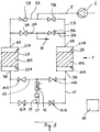
- Figure 1 schematically shows a possible embodiment of an adsorption device 1 according to the invention, which in this case forms a drying device and which comprises two vessels 2A and 2B that are each provided with an inlet 3A and 3B respectively for the supply of a compressed gas to be treated (in this case dried) and an outlet 4A and 4B respectively for the discharge of treated (in this case dried) compressed gas.
- the respective outlets 4A and 4B are connected to a pressure pipe 5 of a compressor 6 via outlet pipes 5A and 5B, in this example an air compressor.
- Each of the outlet pipes 5A and 5B can be shut off by means of an outlet valve 7A and 7B respectively provided to this end.
- each outlet pipe 5A and 5B to a discharge pipe 8A and 8B respectively that can be closed off by means of a discharge valve 9A and 9B respectively, and which in this case, but not necessarily, is connected to a common outlet 10.
- the aforementioned inlets 3A and 3B are connected together by means of a connecting pipe 11 in which a first set of two shutoff valves 12A and 12B are placed in series.
- the valves 12A and 12B concerned are bypassed by a bypass pipe 13 in which a second set of two shutoff valves 14A and 14B are placed in series.
- the connecting pipe 11 and the bypass pipe 13 are connected together by means of a cooling pipe 15, in which a heat exchanger 16 and a condensate separator 17 are affixed.
- One end of the cooling pipe 15 connects to the connecting pipe 11 between the first set of shutoff valves 12A and 12B, while the other end of the cooling pipe 15 is connected to the bypass pipe 13, between the second set of shutoff valves 14A and 14B.
- each of the outlet valves 7A and 7B, the discharge valves 9A and 9B and the shutoff valves 12A, 12B, 14A, 14B are constructed in the form of a controllable shutoff valve that is connected to a control unit 18, either via control cables provided to this end, which for clarity are not included in the drawing, or wirelessly.
- an adsorption element 19A and 19B respectively is affixed in each of the aforementioned vessels 2A and 2B, in this case in the form of drying elements, more specifically in the flow path of the gas to be dried, or in other words according to the flow direction of the compressed gas to be treated between the aforementioned inlet 3A and 3B respectively on the one hand, and the aforementioned outlet 4A and 4B respectively on the other hand.
- an inlet side 20A of the adsorption element 19A will extend opposite the aforementioned inlet 3A, while an outlet side 21A of the adsorption element 19A extends opposite the outlet 4A.
- the adsorption element 19B in the second vessel 2B has an inlet side 20B and an outlet side 21B that extend opposite the inlet 3B and the outlet 4B respectively.
- the adsorption elements 19A and 19B comprise a monolithic supporting structure that preferably, but not necessarily, consists of a ceramic structure that contains cordierite, for example Celcor ⁇ by Corning.
- a monolithic supporting structure that preferably, but not necessarily, consists of a ceramic structure that contains cordierite, for example Celcor ⁇ by Corning.
- other materials can also be used for the manufacture of the supporting structure concerned, such as:
- the monolithic supporting structure is made of a combination of two or more of the aforementioned and/or other materials.
- the material of the supporting structure preferably contains between 200 and 1200 CPSI (cells per square inch), and more preferably between 350 and 450 CPSI.
- the wall thickness of the supporting structure is preferably between 2 and 11 mil (milli-inch), and more preferably between 3 and 9 mil, and even more preferably between 5 and 7.5 mil. In a most preferred embodiment, the wall thickness is between 6 and 7 mil, preferably approximately 6.5 mil.
- the porosity of the wall of the supporting structure is preferably greater than 5%, and more preferably greater than 10%, and even better greater than 20%.
- the cells formed preferably have a square shape, but can present other shapes such as triangular, sinusoidal, circular, hexagonal and similar.
- the aforementioned monolithic supporting structure is at least partially provided with a coating that contains an adsorbent.
- the adsorbent concerned can contain one or more of the following and/or other materials:
- the choice of the adsorbent depends on what treatment the gas to be treated must go through, such as drying or the removal of other molecules such as oxygen or carbon dioxide, for example when using the adsorption device as a nitrogen generator, whereby the compressed gas to be treated is compressed air.
- the distribution of the particle size of the adsorbent is preferably such that D 50 is less than 10 ⁇ m and more preferably less than 4 ⁇ m.
- the aforementioned coating preferably also contains a binder material, preferably an inorganic binder material such as:
- organic binder material such as:
- a seal 22 is provided between two adsorption elements 19A stacked on one another, over the peripheral edge of these adsorption elements 19A, in this case a ringshaped seal that extends between the interfaces of the stacked adsorption elements 19A with at least one radial lip oriented inwards, and in this case with two V-shaped radial lips 23 oriented inwards.
- shrink sleeving 24 is affixed over the peripheral wall of the entire stack of adsorption elements, that is preferably made of an elastic material that is not very permeable to gas, for example polyolefin.
- the shrink sleeving 24 concerned can also be affixed over just a part of the height of the stack of adsorption elements.
- the set of stacked adsorption elements 19A thus forms a cartridge that is interchangeable or replaceable according to a particular aspect of the invention.
- an adsorption device 1 The operation of an adsorption device 1 according to the invention is very simple and as follows.
- the first vessel 2A will fulfil the role of a drying vessel, while the adsorption element 19B (that is thus a drying element here) will be regenerated in the second vessel 2B.
- the compressor 6 draws in a gas, for example surrounding air, and compresses this gas.
- the compressed hot gas is then carried through the outlet pipe 5B via the pressure pipe 5 via the open outlet valve 7B to the outlet 4B of the second vessel 2B.
- the hot compressed gas will have a sufficiently low relative humidity to extract moisture from the adsorption element 19B present in the drying agent and will thus regenerate this adsorption element 19B.
- the desiccant is dried in the second vessel 2B.
- the hot moist gas is then driven via the open shutoff valve 14B to the cooling pipe 15, where it is guided successively through the heat exchanger 16 and the condensate separator 17 to then be carried via the open shutoff valve 12A and the connecting pipe 11 to the inlet 3A of the first vessel 2A.
- the cold compressed gas that is 100% saturated will enter the first vessel 2A via the inlet 3A and be guided through the adsorption element 19A.
- the adsorbent present on the supporting structure will extract moisture from the gas during the flow of the compressed gas through the adsorption element 19A.
- the adsorbent will consequently fulfil the role of a drying agent or desiccant material.
- the gas that leaves the adsorption element 19A, at the outlet side 21A thereof, will be drier than the gas that entered the vessel 2A via the inlet 3A.
- the dried compressed gas then flows, via the outlet 4A, through the outlet pipe 5A and the open discharge valve 9A to the discharge pipe 8A and to the outlet 10 connected thereto, which can be connected to a consumer of dried compressed gas.
- both vessels 2A and 2B can be changed over and the second vessel 2B can take on the role of a drying vessel, while the desiccant in the first vessel 2A can be regenerated.
- the vessels 2A and 2B can be placed in any position such as vertical, horizontal or any other position.
- adsorbent As the adsorbent is attached to a supporting structure there is no risk of fluidisation, such as with a granular desiccant, and consequently dust formation cannot occur, not even at high gas speeds through the adsorption element.
- the gas will flow sequentially through the successive adsorption elements, either as gas to be dried or as a regeneration gas.
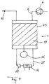
- FIG 4 shows another embodiment of an adsorption device 1 according to the invention, whereby in this case there is only one vessel 25 in which an adsorption element 19 is rotatably affixed.
- the adsorption element 19 is attached to drive means, for example in the form of an electric motor 26.
- a regeneration zone and an adsorption zone extend in the vessel.
- the outlet of the regeneration zone is connected to the inlet of the adsorption zone in a known way via a connecting pipe 27.
- a heat exchanger 16 and condensate separator 17 are provided in the connecting pipe 27 concerned.
- the outlet of the regeneration zone is connected to the outlet 10 via a discharge pipe 8.
- an adsorption device according to figure 4 is analogous to that of known HOC dryers with a rotary drum in which a drying agent is provided.
- a drying agent is provided on account of the structure of the adsorption element 19
- such an improved adsorption device according to the invention is not susceptible to failure on account of a reduction of strength.
- the monolithic supporting structure of an adsorption element in an adsorption device of the invention does not lose structural strength, not even under severe conditions of high humidity and high temperature.
- an adsorption device 1 according to the invention shown in the drawings are both full-flow HOC dryers, however the invention is not limited as such, as an adsorption device 1 according to the invention does not necessarily have to operate according to a full-flow principle. Likewise, according to the invention it is not required either that the heat of compression is employed for the regeneration of the adsorbent, but use can be made of any regeneration gas that originates from the process itself or otherwise, and which is compressed gas or otherwise.
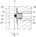
- Figure 5 shows a variant of the detail of claim 3, whereby in this case the stack of adsorption elements 19A is affixed in the vessel 2A and a part of the wall of this vessel 2A can be seen.
- the seal 22 comprises a ring 28, for example but not necessarily of aluminium, another metal or a polymer, whereby the inside diameter of this ring 28 is somewhat larger than the outside diameter of the adsorption elements 19A, which in this example are disc shaped.
- the ring 28 extends over the peripheral edge of the ends of the adsorption elements 19A placed on one another. On its inside periphery the ring 28 concerned is provided with a radial edge 29 oriented inwards, against which the ends concerned of the adsorption elements are affixed.
- a sealing layer 30 and 31 respectively is affixed over the entire periphery on either side of the edge 29 concerned, for example in the form of a quantity of adhesive or another sealing element.
- the ring 28 is provided over its outer periphery with two practically parallel ribs 32 at an axial distance from one another, between which a seal 33 is affixed, in this case in the form of an O-ring.
- the presence of the ribs 32 is not strictly necessary.
- only one rib can be provided on which the seal 33 rests, or can be mounted immovably on the ring 28 of the seal, or form an integral part of this.
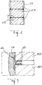
- Figure 6 shows a detail of a top edge of a top part of a stack of adsorption elements 19A in a mounted state in a vessel 2A.
- the wall of the vessel 2A is shown in the right of the drawing.
- the same construction is possible on the bottom edge of a stack of adsorption elements or, when use is made of only one adsorption element in a vessel, on the top and/or bottom side of such a separate adsorption element.
- a V-shaped seal 34 is pushed over the free peripheral edge of the adsorption element 19A, in other words the peripheral edge that is not oriented towards another adsorption element 19A, all such that a first arm 35 of the seal presses against the axial top surface 36 of the adsorption element 19A, while the second arm 37 of this seal 34 presses against the radial outside wall 38 of the adsorption element 19A.
- V-shaped seal 34 presents a lobate protuberance 39 on the top, or in other words on the side where the two arms 35 and 38 are connected together.
- pressing means are provided that press a part of the seal 34 radially against the inside wall of the vessel 2A.
- the pressing means concerned comprise a conical ring 40, that is pressed by means of a spring 41 against the lobate protuberance 39 of the seal 34.
- the conical surface of the conical ring 40 is oriented towards the seal 34 concerned and presses the spring by its other end against the cover of the vessel 2A, for example.
- the part of the seal 34 that is pressed against the inside wall of the vessel 2A does not necessarily have to be lobate, and this part can be constructed in many different ways.
- the largest outside diameter of the conical ring 40 is preferably, but not necessarily, almost as large as the inside diameter of the vessel 2A.
- the seal at the top and bottom of the cartridge consisting of a stack of adsorption elements 19A, can be obtained in different ways, for example by making use of a glued ring and an O-ring similar to the principle shown in figure 5 .
- the invention also relates to other types of adsorption devices such as nitrogen generators and similar, whose adsorption element is able to adsorb certain gas molecules such as oxygen, carbon dioxide and/or similar. By removing such gas molecules from compressed air for example, as is known, nitrogen can be generated.
Description
- The present invention relates to an adsorption device for compressed gas, for example compressed air.
- More specifically, the invention concerns an adsorption device for compressed gas, whereby this adsorption device comprises a vessel in which an adsorbent, for example a drying agent, or a 'desiccant', is placed. The vessel concerned is provided with an inlet for supplying a compressed gas to be treated, and an outlet for discharging treated gas.
- The adsorbent concerned is generally realised in the form of a regeneratable adsorbent, or in other words an adsorbent that can be regenerated after reaching a certain degree of saturation. For simplicity, the following primarily refers to an adsorbent in the form of a drying agent, but the invention also extends to other adsorbents. For example, with a drying device it is indeed the case that as the adsorbent, that is constructed in the form of a drying agent, extracts moisture from the gas to be dried, this drying agent will become increasingly saturated with adsorbed moisture. Hence, it is usual, after using the drying agent for a certain time to dry compressed gas, to regenerate this drying agent, for example by exposing it to a regeneration gas flow that extracts the moisture from the drying agent. Such a regeneration gas flow can consist of a fraction of the dried gas and/or hot gas for example whose relative humidity is sufficiently low to be able to realise the regeneration of the drying agent.
- In some embodiments of drying devices for compressed gas, use is made of two or more vessels of drying agent. With two vessels this principle of drying device is also referred to as a twin tower dryer. In such a type of drying device a compressed gas, for example originating from a compressor, can be passed through the first of the aforementioned vessels for example, where it will be dried by the drying agent in the vessel concerned, after having passed through an after cooler and a condensate separator (which may or may not form part of the after cooler concerned). This vessel consequently acts as a drying vessel.
- At the same time, a regeneration gas flow can be guided through a second aforementioned vessel in order to regenerate the drying agent in that second vessel by extracting the moisture from this drying agent. This can be done by making use of a gas that has already been dried, for example, that is tapped off downstream from the drying vessel for example and/or by supplying a gas flow that has been heated, for example by recovering the heat generated in the compressor during the compression. In this last case it is called a "heat of compression" or HOC dryer. Other known regeneration principles can of course also be used.
- When the drying agent in the drying vessel has reached a certain degree of saturation, the gas flows through the first and the second vessel can be changed over, such that the drying agent in the first vessel will now be regenerated by a regeneration gas flow while the second vessel will take on the role of drying vessel. In this way the two or more vessels will alternately operate as a drying pressure vessel and a regenerating pressure vessel, such that continuity in the drying process can be realised. Examples of such drying devices with a number of vessels are described for example in
US 2003/023.941 ,US 4.783.432 ,US 6.375.722 ,EP 1.776.171 andWO 2006/050.582 . - The drying agent that is used in such adsorption devices with a number of vessels often consists of grains of silica gel, activated alumina or a molecular sieve material, or a combination thereof. As is known activated alumina is produced by thermal dehydration or activation of aluminium hydroxide Al(OH)3, while molecular sieves consist of synthetic zeolites (crystalline aluminosilicates).
- A limitation of such a type of drying device that comprises a drying agent in a granular form, consists of the gas speeds through the vessels having to be limited in order to counteract grains moving against one another or even fluidisation. Indeed, due to the grains being set in motion friction will occur between them, which in turn leads to dust formation and a reduced drying capacity. Other causes of such dust formation are for example pressure variations and/or thermal shocks. Moreover, the pressure drop across a twin tower dryer is relatively high and the desiccant grains have a rather high thermal mass.
- Alternative drying devices are known for compressed gas, whereby the drying agent is placed in a rotating drum, while a drying zone and regeneration zone extend in the vessel. During the operation of such a drying device, the drying drum will be made to rotate by drive means provided to this end, such that the drying agent in this drying drum will alternately be taken through the drying zone and the regeneration zone. The compressed gas to be dried will be guided through the drying zone, while the regeneration gas flow is guided through the regeneration zone, in order to realise simultaneous drying of compressed gas in the drying zone and regeneration of the drying agent in the regeneration zone.
- Examples of such drying devices that are provided with a rotating drying drum are described for example in
WO 00/033.943 WO 00/074.819 WO 01/078.872 WO 01/087.463 WO 02/038.251 WO 2007/079533 ,WO 2005/070.518 ,WO 2006/012.711 ,GB 1.226.348 GB 1.349.732 GB 1.426.292 US 3.490.201 ,US 5.385.603 andUS 8.349.054 . - The drying agent or desiccant that is used in the known drying devices for drying compressed gas consists of silica gel, molecular sieves, activated alumina or a combination thereof, for example. As is known, the drying agent can be affixed on a support such as a corrugated structure of glass fibres or ceramic fibres that are rolled up for example to form a honeycomb structure in the vessel, for example as described in
US 5.683.532 . - In practice it turns out that with the known drying devices for drying compressed gas, under certain conditions such as in the event of insufficient regeneration of the drying agent and oversaturation thereof, the drying agent goes through a complex breakdown process that in some cases can ultimately result in the failure of the drying device, for example in the case of silica gel as a drying agent in a rotor, because the binder function of the silica gel decreases, which leads to a loss of structural strength of the supporting glass fibre matrix, and also because the adsorbing function of the silica gel decreases as a result of hydrolisation and breakdown of the silica gel structure.
- Thus the adsorption behaviour and adsorption capacity of a silica gel rotor, in severe conditions of high moisture and high temperature will substantially change during the useful life of the rotor.
-
EP 2.829.318 A1 discloses an adsorption device with an adsorption element which comprises a monolithic structure such as cordiorite, metal foil or ceramic fibers, a coating suspension comprising a solvent and an adsorbent. -
US 2014/305309 A1 discloses an adsorbent cartridge for removal of gaseous contaminants from air or other gases, the device comprising a plurality of parallel, non-wound adsorbent surfaces, mechanically spaced so as to allow gas flow between each surface and one or more fasteners securing the surfaces together. It does not disclose an "adsorption device for compressed gas". -
US 2015/040765 A1 discloses a breather filter comprising a housing within which a first and second absorber materials are provided. The breather filter being used for removing solid particles in addition to moisture before the fluid is reaching a fluid tank, a hydraulic liquid tank, a liquid fuel tank, or an electronic device container. It does not disclose an adsorption device for compressed gas.The purpose of the present invention is to provide an adsorption device for compressed gas that provides a solution for one or more of the disadvantages attached to the conventional, already known, adsorption devices that make use of an adsorbent. - To this end the invention concerns an adsorption device for compressed gas, according to
claim 1. - An advantage of such an adsorption device according to the invention is that there is no risk of movement or fluidisation, as no loose grains of adsorbent are used. As a result dust formation is prevented, while a relatively high flow rate of the compressed gas to be treated through the adsorption device is possible.
- Moreover, such an adsorption device according to the invention enables the vessel to be placed vertically, sloping or even horizontally, which is not possible with conventional drying devices that make use of a granular drying agent for example, as the horizontal use of such known drying devices can lead to a rearrangement of the grains and the formation of internal leakage paths and consequently a reduced dryer performance.
- According to a preferred characteristic of the invention, the aforementioned monolithic supporting structure comprises one or more of the following materials: ceramic material, metal foil, a fibre structure and a polymer. Particularly good results are obtained with the use of a ceramic structure that contains cordierite.
- Preferably the aforementioned adsorbent contains one or more of the following materials: a zeolite, silica gel, activated alumina, activated carbon, metal organic frameworks, carbon molecular sieve (CMS), an impregnated adsorbent and a hybrid adsorbent. In particular a hydrophilic zeolite support is preferable. Good results are obtained by making use of faujasite or zeolite type X, in which the silicon/aluminium ratio is between 2 and 3.
- According to the invention, the adsorption device comprises a number of adsorption elements placed in series in the aforementioned vessel along the flow direction of the gas.
- The present disclosure also relates to an adsorption element for an adsorption device for compressed gas, whereby this adsorption element comprises a monolithic supporting structure that is at least partially provided with a coating that contains an adsorbent.
- In addition the invention also concerns a cartridge according to
claim 14. - With the intention of better showing the characteristics of the present invention, a few preferred embodiments of an adsorption device according to the invention are described hereinafter by way of an example, without any limiting nature, with reference to the accompanying drawings, wherein:
-
figure 1 schematically shows an adsorption device according to the invention; -
figure 2 shows a cartridge of adsorption elements according to the invention; -
figure 3 shows the part indicated by F3 infigure 2 on a larger scale; -
figure 4 shows a variant of an adsorption device according tofigure 1 ; -
figure 5 shows a variant offigure 3 in the mounted state of the stack of adsorption elements in a vessel; and -
figure 6 shows a detail of the top edge of a stack of adsorption elements in the mounted state in a vessel. -
Figure 1 schematically shows a possible embodiment of anadsorption device 1 according to the invention, which in this case forms a drying device and which comprises twovessels 2A and 2B that are each provided with an inlet 3A and 3B respectively for the supply of a compressed gas to be treated (in this case dried) and anoutlet - The
respective outlets pressure pipe 5 of acompressor 6 viaoutlet pipes outlet pipes outlet valve - Between the
outlet valve outlet outlet pipe discharge pipe discharge valve common outlet 10. - The aforementioned inlets 3A and 3B are connected together by means of a connecting
pipe 11 in which a first set of twoshutoff valves 12A and 12B are placed in series. Thevalves 12A and 12B concerned are bypassed by abypass pipe 13 in which a second set of twoshutoff valves 14A and 14B are placed in series. - The connecting
pipe 11 and thebypass pipe 13 are connected together by means of acooling pipe 15, in which aheat exchanger 16 and acondensate separator 17 are affixed. One end of the coolingpipe 15 connects to the connectingpipe 11 between the first set ofshutoff valves 12A and 12B, while the other end of the coolingpipe 15 is connected to thebypass pipe 13, between the second set ofshutoff valves 14A and 14B. - In this example each of the
outlet valves discharge valves shutoff valves control unit 18, either via control cables provided to this end, which for clarity are not included in the drawing, or wirelessly. - According to the invention, an
adsorption element aforementioned vessels 2A and 2B, in this case in the form of drying elements, more specifically in the flow path of the gas to be dried, or in other words according to the flow direction of the compressed gas to be treated between the aforementioned inlet 3A and 3B respectively on the one hand, and theaforementioned outlet - With regard to the
first vessel 2A, an inlet side 20A of theadsorption element 19A will extend opposite the aforementioned inlet 3A, while anoutlet side 21A of theadsorption element 19A extends opposite theoutlet 4A. - Analogously the
adsorption element 19B in the second vessel 2B has an inlet side 20B and an outlet side 21B that extend opposite the inlet 3B and theoutlet 4B respectively. - According to the invention the
adsorption elements - other ceramic materials such as mullite, γ- or α-alumina or silicon carbide (SiC);
- metal foil; or
- a fibre structure, for example based on glass fibre, ceramic fibre or other fibres, or a mixture of different types of fibres; or
- a polymer.
- It goes without saying that the aforementioned list is not exhaustive and the use of other materials is not excluded.
- According to the invention, it is not excluded either that the monolithic supporting structure is made of a combination of two or more of the aforementioned and/or other materials.
- The material of the supporting structure preferably contains between 200 and 1200 CPSI (cells per square inch), and more preferably between 350 and 450 CPSI.
- The wall thickness of the supporting structure is preferably between 2 and 11 mil (milli-inch), and more preferably between 3 and 9 mil, and even more preferably between 5 and 7.5 mil. In a most preferred embodiment, the wall thickness is between 6 and 7 mil, preferably approximately 6.5 mil.
- The porosity of the wall of the supporting structure is preferably greater than 5%, and more preferably greater than 10%, and even better greater than 20%.
- The cells formed preferably have a square shape, but can present other shapes such as triangular, sinusoidal, circular, hexagonal and similar.
- According to the invention the aforementioned monolithic supporting structure is at least partially provided with a coating that contains an adsorbent.
- According to the invention, the adsorbent concerned can contain one or more of the following and/or other materials:
- a zeolite, preferably a hydrophilic zeolite, but a hydrophobic zeolite is also possible - this zeolite can be faujasite zeolite type X for example, for example Zeolum F9 of Tosoh, or a mixture of zeolite type X and A;
- silica gel;
- activated alumina;
- activated carbon;
- metal-organic frameworks;
- carbon molecular sieve (CMS);
- an impregnated adsorbent; and
- a hybrid adsorbent.
- The above list is not exhaustive and other materials are also possible according to the invention.
- The choice of the adsorbent depends on what treatment the gas to be treated must go through, such as drying or the removal of other molecules such as oxygen or carbon dioxide, for example when using the adsorption device as a nitrogen generator, whereby the compressed gas to be treated is compressed air.
- The distribution of the particle size of the adsorbent is preferably such that D50 is less than 10 µm and more preferably less than 4 µm.
- In addition to the aforementioned adsorbent, the aforementioned coating preferably also contains a binder material, preferably an inorganic binder material such as:
- colloidal silica, for example Ludox-
AS 40 of Grace Davison; - alumina; and/or
- clay.
- Moreover, if need be use can be made of an organic binder material such as:
- methyl cellulose;
- polymers such as acrylic resins, vinyl resins and similar; and/or
- a material from the cellulose group. In the example of
figure 1 eachvessel 2A and 2B contains onesingle adsorption element adsorption device 1 according to the invention, as shown infigure 2 , two ormore adsorption elements vessel 2A and/or 2B along the flow direction of the gas.Figure 2 shows an example of a number ofadsorption elements 19A stacked on one another, which in this example are disc shaped and all present a flat top and bottom surface. - In each case, a
seal 22 is provided between twoadsorption elements 19A stacked on one another, over the peripheral edge of theseadsorption elements 19A, in this case a ringshaped seal that extends between the interfaces of the stackedadsorption elements 19A with at least one radial lip oriented inwards, and in this case with two V-shapedradial lips 23 oriented inwards. - According to the invention, shrink
sleeving 24 is affixed over the peripheral wall of the entire stack of adsorption elements, that is preferably made of an elastic material that is not very permeable to gas, for example polyolefin. Theshrink sleeving 24 concerned can also be affixed over just a part of the height of the stack of adsorption elements. - The set of stacked
adsorption elements 19A thus forms a cartridge that is interchangeable or replaceable according to a particular aspect of the invention. - The operation of an
adsorption device 1 according to the invention is very simple and as follows. - In the first instance, in this example the
first vessel 2A will fulfil the role of a drying vessel, while theadsorption element 19B (that is thus a drying element here) will be regenerated in the second vessel 2B. - The
compressor 6 draws in a gas, for example surrounding air, and compresses this gas. The compressed hot gas is then carried through theoutlet pipe 5B via thepressure pipe 5 via theopen outlet valve 7B to theoutlet 4B of the second vessel 2B. - The hot compressed gas will have a sufficiently low relative humidity to extract moisture from the
adsorption element 19B present in the drying agent and will thus regenerate thisadsorption element 19B. In other words the desiccant is dried in the second vessel 2B. - The hot moist gas is then driven via the
open shutoff valve 14B to the coolingpipe 15, where it is guided successively through theheat exchanger 16 and thecondensate separator 17 to then be carried via theopen shutoff valve 12A and the connectingpipe 11 to the inlet 3A of thefirst vessel 2A. - The cold compressed gas that is 100% saturated will enter the
first vessel 2A via the inlet 3A and be guided through theadsorption element 19A. - The adsorbent present on the supporting structure will extract moisture from the gas during the flow of the compressed gas through the
adsorption element 19A. In this example the adsorbent will consequently fulfil the role of a drying agent or desiccant material. - The gas that leaves the
adsorption element 19A, at theoutlet side 21A thereof, will be drier than the gas that entered thevessel 2A via the inlet 3A. - The dried compressed gas then flows, via the
outlet 4A, through theoutlet pipe 5A and theopen discharge valve 9A to thedischarge pipe 8A and to theoutlet 10 connected thereto, which can be connected to a consumer of dried compressed gas. - After a certain cycle time, the operation of both
vessels 2A and 2B can be changed over and the second vessel 2B can take on the role of a drying vessel, while the desiccant in thefirst vessel 2A can be regenerated. - On account of the fact that the
adsorption device 1 according to the invention does not make use of a granular desiccant, thevessels 2A and 2B can be placed in any position such as vertical, horizontal or any other position. - As the adsorbent is attached to a supporting structure there is no risk of fluidisation, such as with a granular desiccant, and consequently dust formation cannot occur, not even at high gas speeds through the adsorption element.
- When use is made of a number of
adsorption elements 19A placed on one another, as shown infigure 2 , the gas will flow sequentially through the successive adsorption elements, either as gas to be dried or as a regeneration gas. - The presence of the
aforementioned seals 22 betweensuccessive adsorption elements 19A prevents leakages being able to occur between the side wall of the stack ofadsorption elements 19A on the one hand, and the inside wall of thevessel 2A on the other hand. For the rest, the same applies to the use of such a stack of a number ofadsorption elements 19B in the second vessel 2B, which of course is also possible and can be provided with the said seals 22. -
Figure 4 shows another embodiment of anadsorption device 1 according to the invention, whereby in this case there is only onevessel 25 in which anadsorption element 19 is rotatably affixed. Theadsorption element 19 is attached to drive means, for example in the form of anelectric motor 26. - As with known rotary drum dryers a regeneration zone and an adsorption zone (in this case a drying zone) extend in the vessel. The
pressure pipe 5, in this case originating from acompressor 6, connects to the inlet of the regeneration zone, as is the case with known HOC dryers. The outlet of the regeneration zone is connected to the inlet of the adsorption zone in a known way via a connectingpipe 27. Aheat exchanger 16 andcondensate separator 17 are provided in the connectingpipe 27 concerned. - Finally, the outlet of the regeneration zone is connected to the
outlet 10 via a discharge pipe 8. - The operation of an adsorption device according to
figure 4 is analogous to that of known HOC dryers with a rotary drum in which a drying agent is provided. However, on account of the structure of theadsorption element 19, such an improved adsorption device according to the invention is not susceptible to failure on account of a reduction of strength. After all, the monolithic supporting structure of an adsorption element in an adsorption device of the invention does not lose structural strength, not even under severe conditions of high humidity and high temperature. - The embodiments of an
adsorption device 1 according to the invention shown in the drawings are both full-flow HOC dryers, however the invention is not limited as such, as anadsorption device 1 according to the invention does not necessarily have to operate according to a full-flow principle. Likewise, according to the invention it is not required either that the heat of compression is employed for the regeneration of the adsorbent, but use can be made of any regeneration gas that originates from the process itself or otherwise, and which is compressed gas or otherwise. -
Figure 5 shows a variant of the detail of claim 3, whereby in this case the stack ofadsorption elements 19A is affixed in thevessel 2A and a part of the wall of thisvessel 2A can be seen. - In this example the
seal 22 comprises aring 28, for example but not necessarily of aluminium, another metal or a polymer, whereby the inside diameter of thisring 28 is somewhat larger than the outside diameter of theadsorption elements 19A, which in this example are disc shaped. - The
ring 28 extends over the peripheral edge of the ends of theadsorption elements 19A placed on one another. On its inside periphery thering 28 concerned is provided with aradial edge 29 oriented inwards, against which the ends concerned of the adsorption elements are affixed. - In order to obtain a good seal and prevent leakage paths, a
sealing layer 30 and 31 respectively is affixed over the entire periphery on either side of theedge 29 concerned, for example in the form of a quantity of adhesive or another sealing element. - In this example, the
ring 28 is provided over its outer periphery with two practicallyparallel ribs 32 at an axial distance from one another, between which aseal 33 is affixed, in this case in the form of an O-ring. According to the invention the presence of theribs 32 is not strictly necessary. For example, only one rib can be provided on which theseal 33 rests, or can be mounted immovably on thering 28 of the seal, or form an integral part of this. - When mounting the cartridge consisting of adsorption elements stacked on one another, as shown in
figure 5 , theseal 33 will press against the inside wall of thevessel 2A. In this way, this construction not only ensures that leaks between theadsorption elements 19A mutually, but also between the cartridge and the wall of the vessel, are prevented. - Again it is clear that the embodiment concerned is not limited to an application in the
vessel 2A, but it can just as well be applied in the vessel 2B offigure 1 and/or in thevessel 25 offigure 4 , or in any other type ofadsorption device 1 according to the invention. -
Figure 6 shows a detail of a top edge of a top part of a stack ofadsorption elements 19A in a mounted state in avessel 2A. The wall of thevessel 2A is shown in the right of the drawing. The same construction is possible on the bottom edge of a stack of adsorption elements or, when use is made of only one adsorption element in a vessel, on the top and/or bottom side of such a separate adsorption element. - A V-shaped
seal 34 is pushed over the free peripheral edge of theadsorption element 19A, in other words the peripheral edge that is not oriented towards anotheradsorption element 19A, all such that afirst arm 35 of the seal presses against the axialtop surface 36 of theadsorption element 19A, while thesecond arm 37 of thisseal 34 presses against the radial outsidewall 38 of theadsorption element 19A. - In this case, the V-shaped
seal 34 presents alobate protuberance 39 on the top, or in other words on the side where the twoarms - According to a preferred characteristic of the invention, pressing means are provided that press a part of the
seal 34 radially against the inside wall of thevessel 2A. In this example the pressing means concerned comprise aconical ring 40, that is pressed by means of aspring 41 against thelobate protuberance 39 of theseal 34. To this end the conical surface of theconical ring 40 is oriented towards theseal 34 concerned and presses the spring by its other end against the cover of thevessel 2A, for example. It goes without saying that the part of theseal 34 that is pressed against the inside wall of thevessel 2A does not necessarily have to be lobate, and this part can be constructed in many different ways. - The largest outside diameter of the
conical ring 40 is preferably, but not necessarily, almost as large as the inside diameter of thevessel 2A. - Alternatively, in the construction as shown by way of an example in
figure 6 , the seal at the top and bottom of the cartridge, consisting of a stack ofadsorption elements 19A, can be obtained in different ways, for example by making use of a glued ring and an O-ring similar to the principle shown infigure 5 . - Although in the above description an adsorption device in the form of a drying device for adsorbing moisture is primarily described, the invention also relates to other types of adsorption devices such as nitrogen generators and similar, whose adsorption element is able to adsorb certain gas molecules such as oxygen, carbon dioxide and/or similar. By removing such gas molecules from compressed air for example, as is known, nitrogen can be generated.
Claims (21)
- Adsorption device for compressed gas, whereby this adsorption device (1) is provided with a vessel (2A, 2B, 25) with an inlet (3A, 3B) for the supply of a compressed gas to be treated, and an outlet (4A, 4B) for treated gas and whereby an adsorption element (19A, 19B, 19) is affixed in the aforementioned vessel (2A, 2B, 25), whereby this adsorption element (19A, 19B, 19) extends along the flow direction of the compressed gas to be treated, between the aforementioned inlet (3A, 3B) and the aforementioned outlet (4A, 4B), characterised in that the aforementioned adsorption element (19A, 19B, 19) comprises a monolithic supporting structure that is at least partially provided with a coating that contains an adsorbent, in that a number of adsorption elements (19A) are placed in series in the aforementioned vessel (2A, 2B, 25) along the flow direction of the gas, said adsorption elements (19A) being stacked on one another, in that a seal (22) is provided between every two adsorption elements (19A) placed on one another and in that shrink sleeving (24) is affixed over the peripheral wall of the stack of adsorption elements (19A).
- Adsorption device according to claim 1, characterised in that the aforementioned monolithic supporting structure contains one or more of the following materials: ceramic material, metal foil, a fibre structure and a polymer.
- Adsorption device according to claim 2, characterised in that the aforementioned monolithic supporting structure consists of a ceramic structure that contains cordierite.
- Adsorption device according to one or more of the previous claims, characterised in that the aforementioned adsorbent contains one or more of the following materials: a zeolite, silica gel, activated alumina, activated carbon, metal-organic frameworks, an impregnated adsorbent and a hybrid adsorbent.
- Adsorption device according to any one or more of the previous claims, characterised in that the aforementioned seal (22) extends over the respective peripheral edges of the adsorption elements (19A) placed on one another.
- Adsorption device according to claim 5, characterised in that the aforementioned seal (22) is provided with at least one radial lip (23) turned inwards that extends between the adsorption elements (19A).
- Adsorption device according to claim 5, characterised in that the aforementioned seal (22) is provided with two radial V-shaped lips (23) turned inwards, that extend between the adsorption elements (19A) placed on one another.
- Adsorption device according to one or more of the previous claims, characterised in that the aforementioned coating also contains a binder material, in addition to the aforementioned adsorbent.
- Adsorption device according to claim 1, characterised in that a seal (34) is provided over the free peripheral edge of the top edge of a top part of the stack of adsorption elements (19A, 19B, 19).
- Adsorption device according to claim 9, characterised in that the aforementioned seal (34) is constructed as a V-shaped seal that is pushed over the peripheral edge concerned, all such that a first leg (35) of the seal (34) presses against the axial top surface (36) of the adsorption element (19A, 19B, 19), while the second leg (37) of this seal (34) presses against the radial outside wall (38) of the adsorption element (19A, 19B, 19).
- Adsorption device according to claim 9 and/or 10, characterised in that pressing means are provided that press a part of the seal (34) radially against the inside wall of the vessel (2A, 2B).
- Adsorption device according to claim 11, characterised in that the aforementioned pressing means comprise a conical ring (40), that is pressed by means of a spring (41) against a part of the seal (34) .
- Adsorption device according to one or more of the claims 1 to 12, characterised in that the adsorption device forms a drying device for drying compressed gas.
- Cartridge consisting of a stack of adsorption elements for an adsorption device for compressed gas, characterised in that each adsorption element (19A, 19B, 19) comprises a monolithic supporting structure that is at least partially provided with a coating that contains an adsorbent, said adsorption elements (19A) being stacked on one another, whereby a seal (22) is provided between every two adsorption elements (19A) placed on one another and in that shrink sleeving (24) is affixed over the peripheral wall of the stack of adsorption elements (19A).
- Cartridge according to claim 14, characterised in that the aforementioned seal (22) extends over the respective peripheral edges of the adsorption elements (19A) placed on one another.
- Cartridge according to claim 14 or 15, characterised in that the aforementioned seal (22) is provided with at least one radial lip (23) turned inwards that extends between the adsorption elements (19A) .
- Cartridge according to one or more of the claims 14 to 16, characterised in that the aforementioned seal (22) is provided with two radial V-shaped lips (23) turned inwards that extend between adsorption elements (19A) placed on one another.
- Cartridge according to any one or more of the claims 14 to 17, characterised in that the aforementioned monolithic supporting structure consists of a ceramic structure that contains cordierite.
- Cartridge according to any one or more of the claims 14 to 18, characterised in that the aforementioned adsorbent contains a hydrophilic zeolite.
- Cartridge according to any one or more of the claims 14 to 19, characterised in that the aforementioned seal (22) comprises a ring (28) with an inside diameter that is somewhat larger than the outside diameter of the adsorption elements (19A); that the ring (28) extends over the peripheral edge of the ends of the adsorption elements (19A) placed on one another; and that the ring (28) is provided with a radial edge (29) oriented inwards against which the ends concerned of the adsorption elements (19A) are affixed.
- Cartridge according to claim 20, characterised in that a sealing layer (30, 31) is affixed over the entire periphery on at least one side of the radial edge (29) concerned.
Priority Applications (3)
| Application Number | Priority Date | Filing Date | Title |
|---|---|---|---|
| EP20199982.8A EP3785787B1 (en) | 2015-08-31 | 2016-06-14 | Adsorption device for compressed gas |
| EP23201868.9A EP4331707A1 (en) | 2015-08-31 | 2016-06-14 | Adsorption device for compressed gas |
| DK20199982.8T DK3785787T3 (en) | 2015-08-31 | 2016-06-14 | Adsorption device for compressed gas. |
Applications Claiming Priority (3)
| Application Number | Priority Date | Filing Date | Title |
|---|---|---|---|
| US201562212128P | 2015-08-31 | 2015-08-31 | |
| BE20155727A BE1023385A9 (en) | 2015-08-31 | 2015-11-06 | Adsorption device for compressed gas. |
| PCT/BE2016/000026 WO2017035607A1 (en) | 2015-08-31 | 2016-06-14 | Adsorption device for compressed gas |
Related Child Applications (3)
| Application Number | Title | Priority Date | Filing Date |
|---|---|---|---|
| EP20199982.8A Division-Into EP3785787B1 (en) | 2015-08-31 | 2016-06-14 | Adsorption device for compressed gas |
| EP20199982.8A Division EP3785787B1 (en) | 2015-08-31 | 2016-06-14 | Adsorption device for compressed gas |
| EP23201868.9A Division EP4331707A1 (en) | 2015-08-31 | 2016-06-14 | Adsorption device for compressed gas |
Publications (2)
| Publication Number | Publication Date |
|---|---|
| EP3344367A1 EP3344367A1 (en) | 2018-07-11 |
| EP3344367B1 true EP3344367B1 (en) | 2020-11-18 |
Family
ID=75420200
Family Applications (3)
| Application Number | Title | Priority Date | Filing Date |
|---|---|---|---|
| EP20199982.8A Active EP3785787B1 (en) | 2015-08-31 | 2016-06-14 | Adsorption device for compressed gas |
| EP23201868.9A Pending EP4331707A1 (en) | 2015-08-31 | 2016-06-14 | Adsorption device for compressed gas |
| EP16757135.5A Active EP3344367B1 (en) | 2015-08-31 | 2016-06-14 | Adsorption device for compressed gas |
Family Applications Before (2)
| Application Number | Title | Priority Date | Filing Date |
|---|---|---|---|
| EP20199982.8A Active EP3785787B1 (en) | 2015-08-31 | 2016-06-14 | Adsorption device for compressed gas |
| EP23201868.9A Pending EP4331707A1 (en) | 2015-08-31 | 2016-06-14 | Adsorption device for compressed gas |
Country Status (10)
| Country | Link |
|---|---|
| US (3) | US10786779B2 (en) |
| EP (3) | EP3785787B1 (en) |
| JP (3) | JP6854808B2 (en) |
| KR (1) | KR102148581B1 (en) |
| CN (1) | CN106474884B (en) |
| BR (1) | BR112018004008B1 (en) |
| DK (2) | DK3344367T3 (en) |
| PT (2) | PT3785787T (en) |
| RU (1) | RU2727608C2 (en) |
| WO (1) | WO2017035607A1 (en) |
Families Citing this family (8)
| Publication number | Priority date | Publication date | Assignee | Title |
|---|---|---|---|---|
| DE102018212898A1 (en) * | 2018-08-02 | 2020-02-27 | Thyssenkrupp Ag | Regenerative CO2 absorber for a submarine |
| CA3084289A1 (en) * | 2018-08-16 | 2020-02-20 | Commonwealth Scientific And Industrial Research Organisation | Metal organic framework based water capture apparatus |
| KR20210075476A (en) | 2019-12-13 | 2021-06-23 | 주식회사 엘지에너지솔루션 | Pouch-type Battery Cell Having Venting Part and Method for Preparing the Same |
| KR20220009187A (en) | 2020-07-15 | 2022-01-24 | 한국과학기술연구원 | Gas Adsorption Apparatus for Producing Dilution Air |
| BE1029363B1 (en) | 2021-05-03 | 2022-12-06 | Atlas Copco Airpower Nv | Gas purifying device, positioning element and method of assembling a gas purifying device using such a positioning element |
| BE1029448B1 (en) | 2021-06-02 | 2023-01-09 | Atlas Copco Airpower Nv | Device for purifying gas |
| BE1030573B1 (en) | 2022-05-31 | 2024-01-08 | Atlas Copco Airpower Nv | Device for purifying gas |
| BE1030571B1 (en) | 2022-05-31 | 2024-01-08 | Atlas Copco Airpower Nv | Device for purifying gas |
Citations (2)
| Publication number | Priority date | Publication date | Assignee | Title |
|---|---|---|---|---|
| US2930445A (en) * | 1958-01-29 | 1960-03-29 | Westinghouse Air Brake Co | Filter unit |
| FR2974735A1 (en) * | 2011-05-03 | 2012-11-09 | Air Liquide | ADSORBER COMPRISING PARALLEL PASSAGE CONTACTORS WITH INTEGRATED INSULATION |
Family Cites Families (60)
| Publication number | Priority date | Publication date | Assignee | Title |
|---|---|---|---|---|
| US3490201A (en) | 1966-08-05 | 1970-01-20 | Oliver D Colvin | Method and apparatus for drying gases |
| SE335323B (en) | 1967-03-29 | 1971-05-24 | C Munters | |
| SE365720B (en) | 1971-08-06 | 1974-04-01 | Atlas Copco Ab | |
| US3713281A (en) | 1971-11-02 | 1973-01-30 | G Asker | Heat and moisture exchange packing |
| SE368662B (en) | 1972-03-10 | 1974-07-15 | Munters Ab Carl | |
| US4386947A (en) * | 1980-04-25 | 1983-06-07 | Nippon Soken, Inc. | Apparatus for adsorbing fuel vapor |
| JPS5990615A (en) * | 1982-11-17 | 1984-05-25 | Hitachi Ltd | Regenerating method of chemical trap |
| US4550034A (en) | 1984-04-05 | 1985-10-29 | Engelhard Corporation | Method of impregnating ceramic monolithic structures with predetermined amounts of catalyst |
| SU1279657A1 (en) | 1985-06-07 | 1986-12-30 | Предприятие П/Я Г-4150 | Absorber |
| US4783432A (en) | 1987-04-28 | 1988-11-08 | Pall Corporation | Dryer regeneration through heat of compression and pressure swing desorption |
| JPH01270923A (en) * | 1988-04-22 | 1989-10-30 | Osaka Gas Co Ltd | Thermal swing-type adsorption apparatus |
| ES2067629T3 (en) | 1989-11-16 | 1995-04-01 | N E Chemcat Corp | METHOD AND APPARATUS FOR COATING WITH A LIQUID FOR A BEES NEST STRUCTURE. |
| US5683532A (en) | 1990-08-12 | 1997-11-04 | Kabushiki Kaisha Seibu Giken | Method of manufacturing an active silica gel honeycomb adsorbing body usable in an atmosphere having 100% relative humidity |
| EP0526077A1 (en) * | 1991-07-22 | 1993-02-03 | Takeda Chemical Industries, Ltd. | Activated carbon honeycombs and applications thereof |
| BE1005764A3 (en) | 1992-04-15 | 1994-01-18 | Atlas Copco Airpower Nv | Device for drying a gas. |
| US5512083A (en) * | 1993-10-25 | 1996-04-30 | Uop | Process and apparatus for dehumidification and VOC odor remediation |
| JP3000280U (en) * | 1994-01-19 | 1994-08-02 | 内山工業株式会社 | Bearing sealing device |
| CA2147112A1 (en) * | 1994-05-26 | 1995-11-27 | Kishor Purushottam Gadkaree | Electrically heatable activated carbon bodies for adsorption and desorption applications |
| DE19645009A1 (en) * | 1996-10-31 | 1998-05-07 | Ultrafilter Gmbh | Container of a drying plant with adsorbent |
| RU2106528C1 (en) * | 1997-03-26 | 1998-03-10 | Леонид Григорьевич Кузнецов | Method of drying compressed gas |
| DE69906370T2 (en) | 1998-12-09 | 2003-12-18 | Domnick Hunter Ltd Durham | GAS DRYER |
| RU2144419C1 (en) * | 1998-12-28 | 2000-01-20 | Дочернее акционерное общество "Центральное конструкторское бюро нефтеаппаратуры" Открытого акционерного общества "Газпром" | Method of gas adsorption drying |
| WO2000074819A1 (en) | 1999-06-04 | 2000-12-14 | Flair Corporation | Rotating drum adsorber process and system |
| DE19955898A1 (en) * | 1999-11-20 | 2001-05-23 | Mann & Hummel Filter | Drying box for compressor air has solid drying agent body with shape stability in housing between inflow and oil separator and outflow for light weight and easy installation |
| JP2001205045A (en) * | 2000-01-25 | 2001-07-31 | Tokyo Electric Power Co Inc:The | Method of removing carbon dioxide and carbon dioxide removing apparatus |
| BE1013389A3 (en) | 2000-04-13 | 2001-12-04 | Atlas Copco Airpower Nv | Compressor installation with a dry device. |
| BE1013441A3 (en) | 2000-05-17 | 2002-01-15 | Atlas Copco Airpower Nv | COMPRESSOR INSTALLATION WITH A heatless and ADSORPTION DRYER therefor. |
| US6375722B1 (en) | 2000-08-22 | 2002-04-23 | Henderson Engineering Co., Inc. | Heat of compression dryer |
| BE1013828A3 (en) | 2000-11-08 | 2002-09-03 | Atlas Copco Airpower Nv | Method for controlling a compressor plant with a dryer and thus used compressor installation. |
| EP2826552A1 (en) * | 2001-01-05 | 2015-01-21 | Air Products And Chemicals, Inc. | Slurry employed to obtain adsorbent laminates for psa processes and its method of preparation |
| US6957403B2 (en) | 2001-03-30 | 2005-10-18 | Syntest Technologies, Inc. | Computer-aided design system to automate scan synthesis at register-transfer level |
| US6814771B2 (en) * | 2001-11-30 | 2004-11-09 | Delphi Technologies, Inc. | Evaporative emissions control device with internal seals |
| EP2243537B1 (en) | 2002-10-28 | 2016-05-04 | Donaldson Company, Inc. | Air cleaner |
| CN2579505Y (en) * | 2002-10-31 | 2003-10-15 | 陈泽枝 | Organic waste gas purifying device |
| JP3896343B2 (en) * | 2003-04-25 | 2007-03-22 | 東京エレクトロン株式会社 | Dry air supply device |
| US7166149B2 (en) | 2004-01-12 | 2007-01-23 | Uop Llc | Adsorption process for continuous purification of high value gas feeds |
| BE1016145A3 (en) | 2004-08-02 | 2006-04-04 | Atlas Copco Airpower Nv | IMPROVED COMPRESSOR DEVICE. |
| BE1016149A3 (en) | 2004-08-04 | 2006-04-04 | Atlas Copco Airpower Nv | METHOD FOR DRYING A GAS AND DEVICE APPLIED THEREOF |
| BE1016309A3 (en) | 2004-11-10 | 2006-07-04 | Atlas Copco Airpower Nv | METHOD FOR DRYING COMPRESSED GAS AND APPARATUS APPLIED THEREOF |
| US20060208004A1 (en) | 2005-01-18 | 2006-09-21 | Feather Keith F | Substrate Coating System |
| US8882874B1 (en) * | 2005-10-13 | 2014-11-11 | Jonathan Cross | Flexible, multi-cartridge, reconfigurable/selectable air contaminant control system and method for fuel cells |
| JP4231869B2 (en) * | 2005-12-09 | 2009-03-04 | シャープ株式会社 | Biochemical sensor and measuring device |
| WO2007079533A1 (en) | 2006-01-10 | 2007-07-19 | South Eastern Sydney And Illawarra Area Health Service | Method for establishing and proliferating human esc by co-culturing with allogeneic feeder cells in serum-free media |
| BE1016987A3 (en) | 2006-02-10 | 2007-11-06 | Atlas Copco Airpower Nv | IMPROVED FLOW DEVICE FOR HANDLING A FLUID AND FLOW ELEMENT THEREFORE APPLIED. |
| US7722705B2 (en) * | 2006-05-11 | 2010-05-25 | Corning Incorporated | Activated carbon honeycomb catalyst beds and methods for the use thereof |
| JP5141063B2 (en) | 2007-03-26 | 2013-02-13 | トヨタ自動車株式会社 | Exhaust gas purification device |
| RU66691U1 (en) | 2007-04-26 | 2007-09-27 | Леонид Григорьевич Кузнецов | DEVICE FOR DRYING AND CLEANING COMPRESSED GAS |
| AU2008254535B2 (en) * | 2007-05-18 | 2012-05-31 | Exxonmobil Upstream Research Company | Temperature swing adsorption of CO2 from flue gas using a parallel channel contactor |
| US8007731B2 (en) * | 2007-08-10 | 2011-08-30 | Corning Incorporated | Fluid treatment device having a multiple ceramic honeycomb layered structure |
| JP5120542B2 (en) | 2007-10-16 | 2013-01-16 | オリオン機械株式会社 | Insert cartridge |
| US7909919B2 (en) * | 2008-03-10 | 2011-03-22 | Aisan Kogyo Kabushiki Kaisha | Vaporized fuel treatment apparatus |
| JP5107216B2 (en) * | 2008-11-25 | 2012-12-26 | 愛三工業株式会社 | Evaporative fuel processing equipment |
| CN102325590A (en) | 2008-12-19 | 2012-01-18 | 康宁股份有限公司 | The flow-through substrate and preparation and the method for using that apply |
| EP2332631B1 (en) | 2009-12-03 | 2012-11-14 | Kaeser Kompressoren GmbH | Absorption drying device and absorption drying method |
| US8685153B2 (en) * | 2010-01-26 | 2014-04-01 | Micropore, Inc. | Adsorbent system for removal of gaseous contaminants |
| US8821619B2 (en) * | 2010-10-14 | 2014-09-02 | Micropore, Inc. | Adsorbent cartridge assembly with end cap |
| EA026681B1 (en) * | 2011-03-01 | 2017-05-31 | Эксонмобил Апстрим Рисерч Компани | Apparatus and systems having an encased adsorbent contractor and swing adsorption processes related thereto |
| US20150040765A1 (en) * | 2012-03-06 | 2015-02-12 | Donaldson Company, Inc. | Filter for humidity control, typically for control of humidity in a bulk liquid tank |
| CN203090713U (en) * | 2012-12-17 | 2013-07-31 | 孔令德 | Chemical toxic gas filter device |
| WO2016057285A1 (en) * | 2014-10-06 | 2016-04-14 | Corning Incorporated | Honeycomb filter article and methods thereof |
-
2016
- 2016-06-14 DK DK16757135.5T patent/DK3344367T3/en active
- 2016-06-14 JP JP2018511113A patent/JP6854808B2/en active Active
- 2016-06-14 EP EP20199982.8A patent/EP3785787B1/en active Active
- 2016-06-14 KR KR1020187008994A patent/KR102148581B1/en active IP Right Grant
- 2016-06-14 EP EP23201868.9A patent/EP4331707A1/en active Pending
- 2016-06-14 BR BR112018004008-8A patent/BR112018004008B1/en active IP Right Grant
- 2016-06-14 US US15/755,101 patent/US10786779B2/en active Active
- 2016-06-14 RU RU2019112315A patent/RU2727608C2/en active
- 2016-06-14 PT PT201999828T patent/PT3785787T/en unknown
- 2016-06-14 PT PT167571355T patent/PT3344367T/en unknown
- 2016-06-14 DK DK20199982.8T patent/DK3785787T3/en active
- 2016-06-14 EP EP16757135.5A patent/EP3344367B1/en active Active
- 2016-06-14 WO PCT/BE2016/000026 patent/WO2017035607A1/en active Application Filing
- 2016-08-01 CN CN201610619813.8A patent/CN106474884B/en active Active
-
2020
- 2020-09-25 US US17/032,003 patent/US11628398B2/en active Active
-
2021
- 2021-03-16 JP JP2021042162A patent/JP7289865B2/en active Active
-
2023
- 2023-04-17 US US18/135,207 patent/US20230249124A1/en active Pending
- 2023-05-31 JP JP2023089439A patent/JP2023123457A/en active Pending
Patent Citations (2)
| Publication number | Priority date | Publication date | Assignee | Title |
|---|---|---|---|---|
| US2930445A (en) * | 1958-01-29 | 1960-03-29 | Westinghouse Air Brake Co | Filter unit |
| FR2974735A1 (en) * | 2011-05-03 | 2012-11-09 | Air Liquide | ADSORBER COMPRISING PARALLEL PASSAGE CONTACTORS WITH INTEGRATED INSULATION |
Also Published As
| Publication number | Publication date |
|---|---|
| DK3785787T3 (en) | 2024-02-12 |
| JP7289865B2 (en) | 2023-06-12 |
| PT3344367T (en) | 2021-03-18 |
| US20180243686A1 (en) | 2018-08-30 |
| US11628398B2 (en) | 2023-04-18 |
| BR112018004008B1 (en) | 2022-08-30 |
| RU2019112315A3 (en) | 2020-03-17 |
| PT3785787T (en) | 2024-01-29 |
| JP2021102211A (en) | 2021-07-15 |
| KR102148581B1 (en) | 2020-08-27 |
| EP4331707A1 (en) | 2024-03-06 |
| WO2017035607A1 (en) | 2017-03-09 |
| JP2018526209A (en) | 2018-09-13 |
| EP3344367A1 (en) | 2018-07-11 |
| US20210106945A1 (en) | 2021-04-15 |
| RU2019112315A (en) | 2019-06-13 |
| US10786779B2 (en) | 2020-09-29 |
| CN106474884A (en) | 2017-03-08 |
| CN106474884B (en) | 2020-08-18 |
| EP3785787B1 (en) | 2023-11-15 |
| KR20180044413A (en) | 2018-05-02 |
| JP6854808B2 (en) | 2021-04-07 |
| EP3785787A1 (en) | 2021-03-03 |
| DK3344367T3 (en) | 2020-12-07 |
| RU2727608C2 (en) | 2020-07-22 |
| JP2023123457A (en) | 2023-09-05 |
| BR112018004008A2 (en) | 2018-10-02 |
| US20230249124A1 (en) | 2023-08-10 |
Similar Documents
| Publication | Publication Date | Title |
|---|---|---|
| US11628398B2 (en) | Adsorption device for compressed gas | |
| US20240082822A1 (en) | Method for producing an adsorption agent for treating compressed gas and an adsorption device provided with such an adsorption agent | |
| KR20160106549A (en) | High performance adsorbent media for concentrator systems | |
| US7326277B1 (en) | Brake air drying using low pressure desiccant wheel | |
| RU2693751C1 (en) | Adsorption device for compressed gas | |
| JP2004209420A (en) | Dehumidification element and dehumidification apparatus | |
| US20080083336A1 (en) | Electrically conductive adsorptive honeycombs for drying of air | |
| CN214287424U (en) | Two filter cartridge VOCs adsorption equipment based on modified fly ash material | |
| JP2007117942A (en) | Dehumidifying element and dehumidifying device |
Legal Events
| Date | Code | Title | Description |
|---|---|---|---|
| STAA | Information on the status of an ep patent application or granted ep patent |
Free format text: STATUS: THE INTERNATIONAL PUBLICATION HAS BEEN MADE |
|
| PUAI | Public reference made under article 153(3) epc to a published international application that has entered the european phase |
Free format text: ORIGINAL CODE: 0009012 |
|
| STAA | Information on the status of an ep patent application or granted ep patent |
Free format text: STATUS: REQUEST FOR EXAMINATION WAS MADE |
|
| 17P | Request for examination filed |
Effective date: 20180306 |
|
| AK | Designated contracting states |
Kind code of ref document: A1 Designated state(s): AL AT BE BG CH CY CZ DE DK EE ES FI FR GB GR HR HU IE IS IT LI LT LU LV MC MK MT NL NO PL PT RO RS SE SI SK SM TR |
|
| AX | Request for extension of the european patent |
Extension state: BA ME |
|
| DAV | Request for validation of the european patent (deleted) | ||
| DAX | Request for extension of the european patent (deleted) | ||
| STAA | Information on the status of an ep patent application or granted ep patent |
Free format text: STATUS: EXAMINATION IS IN PROGRESS |
|
| 17Q | First examination report despatched |
Effective date: 20200225 |
|
| REG | Reference to a national code |
Ref country code: DE Ref legal event code: R079 Ref document number: 602016048099 Country of ref document: DE Free format text: PREVIOUS MAIN CLASS: B01D0053020000 Ipc: B01D0053260000 |
|
| GRAP | Despatch of communication of intention to grant a patent |
Free format text: ORIGINAL CODE: EPIDOSNIGR1 |
|
| STAA | Information on the status of an ep patent application or granted ep patent |
Free format text: STATUS: GRANT OF PATENT IS INTENDED |
|
| RIC1 | Information provided on ipc code assigned before grant |
Ipc: F16J 15/00 20060101ALI20200625BHEP Ipc: B01J 20/28 20060101ALI20200625BHEP Ipc: B01D 53/26 20060101AFI20200625BHEP Ipc: B01D 53/04 20060101ALI20200625BHEP Ipc: B01J 20/32 20060101ALI20200625BHEP Ipc: B01D 53/02 20060101ALI20200625BHEP |
|
| INTG | Intention to grant announced |
Effective date: 20200720 |
|
| GRAS | Grant fee paid |
Free format text: ORIGINAL CODE: EPIDOSNIGR3 |
|
| GRAA | (expected) grant |
Free format text: ORIGINAL CODE: 0009210 |
|
| STAA | Information on the status of an ep patent application or granted ep patent |
Free format text: STATUS: THE PATENT HAS BEEN GRANTED |
|
| AK | Designated contracting states |
Kind code of ref document: B1 Designated state(s): AL AT BE BG CH CY CZ DE DK EE ES FI FR GB GR HR HU IE IS IT LI LT LU LV MC MK MT NL NO PL PT RO RS SE SI SK SM TR |
|
| REG | Reference to a national code |
Ref country code: GB Ref legal event code: FG4D |
|
| REG | Reference to a national code |
Ref country code: CH Ref legal event code: EP |
|
| REG | Reference to a national code |
Ref country code: DK Ref legal event code: T3 Effective date: 20201203 |
|
| REG | Reference to a national code |
Ref country code: IE Ref legal event code: FG4D |
|
| REG | Reference to a national code |
Ref country code: DE Ref legal event code: R096 Ref document number: 602016048099 Country of ref document: DE |
|
| REG | Reference to a national code |
Ref country code: AT Ref legal event code: REF Ref document number: 1335120 Country of ref document: AT Kind code of ref document: T Effective date: 20201215 |
|
| REG | Reference to a national code |
Ref country code: SE Ref legal event code: TRGR |
|
| REG | Reference to a national code |
Ref country code: PT Ref legal event code: SC4A Ref document number: 3344367 Country of ref document: PT Date of ref document: 20210318 Kind code of ref document: T Free format text: AVAILABILITY OF NATIONAL TRANSLATION Effective date: 20210311 |
|
| REG | Reference to a national code |
Ref country code: AT Ref legal event code: MK05 Ref document number: 1335120 Country of ref document: AT Kind code of ref document: T Effective date: 20201118 |
|
| REG | Reference to a national code |
Ref country code: NL Ref legal event code: MP Effective date: 20201118 |
|
| PG25 | Lapsed in a contracting state [announced via postgrant information from national office to epo] |
Ref country code: GR Free format text: LAPSE BECAUSE OF FAILURE TO SUBMIT A TRANSLATION OF THE DESCRIPTION OR TO PAY THE FEE WITHIN THE PRESCRIBED TIME-LIMIT Effective date: 20210219 Ref country code: FI Free format text: LAPSE BECAUSE OF FAILURE TO SUBMIT A TRANSLATION OF THE DESCRIPTION OR TO PAY THE FEE WITHIN THE PRESCRIBED TIME-LIMIT Effective date: 20201118 Ref country code: RS Free format text: LAPSE BECAUSE OF FAILURE TO SUBMIT A TRANSLATION OF THE DESCRIPTION OR TO PAY THE FEE WITHIN THE PRESCRIBED TIME-LIMIT Effective date: 20201118 Ref country code: NO Free format text: LAPSE BECAUSE OF FAILURE TO SUBMIT A TRANSLATION OF THE DESCRIPTION OR TO PAY THE FEE WITHIN THE PRESCRIBED TIME-LIMIT Effective date: 20210218 |
|
| REG | Reference to a national code |
Ref country code: RO Ref legal event code: EPE |
|
| PG25 | Lapsed in a contracting state [announced via postgrant information from national office to epo] |
Ref country code: AT Free format text: LAPSE BECAUSE OF FAILURE TO SUBMIT A TRANSLATION OF THE DESCRIPTION OR TO PAY THE FEE WITHIN THE PRESCRIBED TIME-LIMIT Effective date: 20201118 Ref country code: IS Free format text: LAPSE BECAUSE OF FAILURE TO SUBMIT A TRANSLATION OF THE DESCRIPTION OR TO PAY THE FEE WITHIN THE PRESCRIBED TIME-LIMIT Effective date: 20210318 Ref country code: PL Free format text: LAPSE BECAUSE OF FAILURE TO SUBMIT A TRANSLATION OF THE DESCRIPTION OR TO PAY THE FEE WITHIN THE PRESCRIBED TIME-LIMIT Effective date: 20201118 Ref country code: LV Free format text: LAPSE BECAUSE OF FAILURE TO SUBMIT A TRANSLATION OF THE DESCRIPTION OR TO PAY THE FEE WITHIN THE PRESCRIBED TIME-LIMIT Effective date: 20201118 Ref country code: BG Free format text: LAPSE BECAUSE OF FAILURE TO SUBMIT A TRANSLATION OF THE DESCRIPTION OR TO PAY THE FEE WITHIN THE PRESCRIBED TIME-LIMIT Effective date: 20210218 |
|
| REG | Reference to a national code |
Ref country code: LT Ref legal event code: MG9D |
|
| PG25 | Lapsed in a contracting state [announced via postgrant information from national office to epo] |
Ref country code: HR Free format text: LAPSE BECAUSE OF FAILURE TO SUBMIT A TRANSLATION OF THE DESCRIPTION OR TO PAY THE FEE WITHIN THE PRESCRIBED TIME-LIMIT Effective date: 20201118 |
|
| PG25 | Lapsed in a contracting state [announced via postgrant information from national office to epo] |
Ref country code: EE Free format text: LAPSE BECAUSE OF FAILURE TO SUBMIT A TRANSLATION OF THE DESCRIPTION OR TO PAY THE FEE WITHIN THE PRESCRIBED TIME-LIMIT Effective date: 20201118 Ref country code: CZ Free format text: LAPSE BECAUSE OF FAILURE TO SUBMIT A TRANSLATION OF THE DESCRIPTION OR TO PAY THE FEE WITHIN THE PRESCRIBED TIME-LIMIT Effective date: 20201118 Ref country code: SM Free format text: LAPSE BECAUSE OF FAILURE TO SUBMIT A TRANSLATION OF THE DESCRIPTION OR TO PAY THE FEE WITHIN THE PRESCRIBED TIME-LIMIT Effective date: 20201118 Ref country code: LT Free format text: LAPSE BECAUSE OF FAILURE TO SUBMIT A TRANSLATION OF THE DESCRIPTION OR TO PAY THE FEE WITHIN THE PRESCRIBED TIME-LIMIT Effective date: 20201118 Ref country code: SK Free format text: LAPSE BECAUSE OF FAILURE TO SUBMIT A TRANSLATION OF THE DESCRIPTION OR TO PAY THE FEE WITHIN THE PRESCRIBED TIME-LIMIT Effective date: 20201118 |
|
| REG | Reference to a national code |
Ref country code: ES Ref legal event code: FG2A Ref document number: 2848425 Country of ref document: ES Kind code of ref document: T3 Effective date: 20210809 |
|
| REG | Reference to a national code |
Ref country code: DE Ref legal event code: R097 Ref document number: 602016048099 Country of ref document: DE |
|
| PLBE | No opposition filed within time limit |
Free format text: ORIGINAL CODE: 0009261 |
|
| STAA | Information on the status of an ep patent application or granted ep patent |
Free format text: STATUS: NO OPPOSITION FILED WITHIN TIME LIMIT |
|
| 26N | No opposition filed |
Effective date: 20210819 |
|
| PG25 | Lapsed in a contracting state [announced via postgrant information from national office to epo] |
Ref country code: NL Free format text: LAPSE BECAUSE OF FAILURE TO SUBMIT A TRANSLATION OF THE DESCRIPTION OR TO PAY THE FEE WITHIN THE PRESCRIBED TIME-LIMIT Effective date: 20201118 Ref country code: AL Free format text: LAPSE BECAUSE OF FAILURE TO SUBMIT A TRANSLATION OF THE DESCRIPTION OR TO PAY THE FEE WITHIN THE PRESCRIBED TIME-LIMIT Effective date: 20201118 |
|
| PG25 | Lapsed in a contracting state [announced via postgrant information from national office to epo] |
Ref country code: SI Free format text: LAPSE BECAUSE OF FAILURE TO SUBMIT A TRANSLATION OF THE DESCRIPTION OR TO PAY THE FEE WITHIN THE PRESCRIBED TIME-LIMIT Effective date: 20201118 |
|
| PG25 | Lapsed in a contracting state [announced via postgrant information from national office to epo] |
Ref country code: IS Free format text: LAPSE BECAUSE OF FAILURE TO SUBMIT A TRANSLATION OF THE DESCRIPTION OR TO PAY THE FEE WITHIN THE PRESCRIBED TIME-LIMIT Effective date: 20210318 |
|
| PG25 | Lapsed in a contracting state [announced via postgrant information from national office to epo] |
Ref country code: CY Free format text: LAPSE BECAUSE OF FAILURE TO SUBMIT A TRANSLATION OF THE DESCRIPTION OR TO PAY THE FEE WITHIN THE PRESCRIBED TIME-LIMIT Effective date: 20201118 |
|
| P01 | Opt-out of the competence of the unified patent court (upc) registered |
Effective date: 20230602 |
|
| PG25 | Lapsed in a contracting state [announced via postgrant information from national office to epo] |
Ref country code: HU Free format text: LAPSE BECAUSE OF FAILURE TO SUBMIT A TRANSLATION OF THE DESCRIPTION OR TO PAY THE FEE WITHIN THE PRESCRIBED TIME-LIMIT; INVALID AB INITIO Effective date: 20160614 |
|
| PGFP | Annual fee paid to national office [announced via postgrant information from national office to epo] |
Ref country code: RO Payment date: 20230525 Year of fee payment: 8 Ref country code: PT Payment date: 20230530 Year of fee payment: 8 Ref country code: MC Payment date: 20230522 Year of fee payment: 8 Ref country code: IE Payment date: 20230627 Year of fee payment: 8 Ref country code: FR Payment date: 20230626 Year of fee payment: 8 Ref country code: DK Payment date: 20230628 Year of fee payment: 8 Ref country code: DE Payment date: 20230626 Year of fee payment: 8 |
|
| PGFP | Annual fee paid to national office [announced via postgrant information from national office to epo] |
Ref country code: SE Payment date: 20230627 Year of fee payment: 8 Ref country code: LU Payment date: 20230627 Year of fee payment: 8 |
|
| PGFP | Annual fee paid to national office [announced via postgrant information from national office to epo] |
Ref country code: BE Payment date: 20230627 Year of fee payment: 8 |
|
| PGFP | Annual fee paid to national office [announced via postgrant information from national office to epo] |
Ref country code: IT Payment date: 20230620 Year of fee payment: 8 Ref country code: GB Payment date: 20230627 Year of fee payment: 8 Ref country code: ES Payment date: 20230703 Year of fee payment: 8 Ref country code: CH Payment date: 20230702 Year of fee payment: 8 |