EP3344012A1 - Treiberschaltung für lichtquellen, insbesondere für ein fahrzeuglicht - Google Patents
Treiberschaltung für lichtquellen, insbesondere für ein fahrzeuglicht Download PDFInfo
- Publication number
- EP3344012A1 EP3344012A1 EP17210912.6A EP17210912A EP3344012A1 EP 3344012 A1 EP3344012 A1 EP 3344012A1 EP 17210912 A EP17210912 A EP 17210912A EP 3344012 A1 EP3344012 A1 EP 3344012A1
- Authority
- EP
- European Patent Office
- Prior art keywords
- voltage
- terminal
- power supply
- driver circuit
- value
- Prior art date
- Legal status (The legal status is an assumption and is not a legal conclusion. Google has not performed a legal analysis and makes no representation as to the accuracy of the status listed.)
- Granted
Links
- 230000033228 biological regulation Effects 0.000 claims abstract description 38
- 239000003990 capacitor Substances 0.000 claims description 25
- 230000008859 change Effects 0.000 claims description 4
- 230000001105 regulatory effect Effects 0.000 claims 1
- 238000010586 diagram Methods 0.000 description 18
- 230000004044 response Effects 0.000 description 7
- 230000009471 action Effects 0.000 description 4
- 230000004913 activation Effects 0.000 description 4
- 230000007423 decrease Effects 0.000 description 4
- 230000005669 field effect Effects 0.000 description 4
- 230000003044 adaptive effect Effects 0.000 description 2
- 230000032683 aging Effects 0.000 description 2
- 230000006978 adaptation Effects 0.000 description 1
- 230000001419 dependent effect Effects 0.000 description 1
- 238000001514 detection method Methods 0.000 description 1
- 238000007599 discharging Methods 0.000 description 1
- 230000003071 parasitic effect Effects 0.000 description 1
- 238000005192 partition Methods 0.000 description 1
- 230000000630 rising effect Effects 0.000 description 1
Images


Classifications
-
- H—ELECTRICITY
- H05—ELECTRIC TECHNIQUES NOT OTHERWISE PROVIDED FOR
- H05B—ELECTRIC HEATING; ELECTRIC LIGHT SOURCES NOT OTHERWISE PROVIDED FOR; CIRCUIT ARRANGEMENTS FOR ELECTRIC LIGHT SOURCES, IN GENERAL
- H05B45/00—Circuit arrangements for operating light-emitting diodes [LED]
- H05B45/30—Driver circuits
- H05B45/395—Linear regulators
-
- H—ELECTRICITY
- H05—ELECTRIC TECHNIQUES NOT OTHERWISE PROVIDED FOR
- H05B—ELECTRIC HEATING; ELECTRIC LIGHT SOURCES NOT OTHERWISE PROVIDED FOR; CIRCUIT ARRANGEMENTS FOR ELECTRIC LIGHT SOURCES, IN GENERAL
- H05B45/00—Circuit arrangements for operating light-emitting diodes [LED]
- H05B45/10—Controlling the intensity of the light
-
- H—ELECTRICITY
- H05—ELECTRIC TECHNIQUES NOT OTHERWISE PROVIDED FOR
- H05B—ELECTRIC HEATING; ELECTRIC LIGHT SOURCES NOT OTHERWISE PROVIDED FOR; CIRCUIT ARRANGEMENTS FOR ELECTRIC LIGHT SOURCES, IN GENERAL
- H05B45/00—Circuit arrangements for operating light-emitting diodes [LED]
- H05B45/30—Driver circuits
- H05B45/347—Dynamic headroom control [DHC]
-
- H—ELECTRICITY
- H05—ELECTRIC TECHNIQUES NOT OTHERWISE PROVIDED FOR
- H05B—ELECTRIC HEATING; ELECTRIC LIGHT SOURCES NOT OTHERWISE PROVIDED FOR; CIRCUIT ARRANGEMENTS FOR ELECTRIC LIGHT SOURCES, IN GENERAL
- H05B45/00—Circuit arrangements for operating light-emitting diodes [LED]
- H05B45/40—Details of LED load circuits
- H05B45/44—Details of LED load circuits with an active control inside an LED matrix
- H05B45/46—Details of LED load circuits with an active control inside an LED matrix having LEDs disposed in parallel lines
-
- B—PERFORMING OPERATIONS; TRANSPORTING
- B60—VEHICLES IN GENERAL
- B60Q—ARRANGEMENT OF SIGNALLING OR LIGHTING DEVICES, THE MOUNTING OR SUPPORTING THEREOF OR CIRCUITS THEREFOR, FOR VEHICLES IN GENERAL
- B60Q1/00—Arrangement of optical signalling or lighting devices, the mounting or supporting thereof or circuits therefor
- B60Q1/02—Arrangement of optical signalling or lighting devices, the mounting or supporting thereof or circuits therefor the devices being primarily intended to illuminate the way ahead or to illuminate other areas of way or environments
- B60Q1/04—Arrangement of optical signalling or lighting devices, the mounting or supporting thereof or circuits therefor the devices being primarily intended to illuminate the way ahead or to illuminate other areas of way or environments the devices being headlights
-
- Y—GENERAL TAGGING OF NEW TECHNOLOGICAL DEVELOPMENTS; GENERAL TAGGING OF CROSS-SECTIONAL TECHNOLOGIES SPANNING OVER SEVERAL SECTIONS OF THE IPC; TECHNICAL SUBJECTS COVERED BY FORMER USPC CROSS-REFERENCE ART COLLECTIONS [XRACs] AND DIGESTS
- Y02—TECHNOLOGIES OR APPLICATIONS FOR MITIGATION OR ADAPTATION AGAINST CLIMATE CHANGE
- Y02B—CLIMATE CHANGE MITIGATION TECHNOLOGIES RELATED TO BUILDINGS, e.g. HOUSING, HOUSE APPLIANCES OR RELATED END-USER APPLICATIONS
- Y02B20/00—Energy efficient lighting technologies, e.g. halogen lamps or gas discharge lamps
- Y02B20/30—Semiconductor lamps, e.g. solid state lamps [SSL] light emitting diodes [LED] or organic LED [OLED]
Definitions
- the present invention relates to a control circuit of lighting sources, in particular for an automotive headlight. More precisely, the invention relates to an adaptive electronic control for one or more lighting sources that may undergo large variations of their activation voltage (Vforward), such as OLED or LED. Such variations of the activation voltage are due for example to a temperature change, or to a voltage selection or to a flow selection.
- Vforward activation voltage
- OLED organic light-emitting diode
- variable voltage drops to be compensated are typically due to the activation voltage at the terminals of the lighting source, as mentioned above, but may also be caused by voltage drops on other devices connected in the lighting branch.
- an adaptive control circuit provides for supplying a supply voltage via a power supply 1 according to the circuit diagram in figure 1 .
- a current controller 2 is connected in series to the lighting source 3 to maintain the drive current of the lighting source at a predetermined value.
- power supplies have a feedback circuit, for example implemented with a voltage divider 4 and an operational amplifier which compares a partition of the output voltage Vout with an internal reference voltage, so as to keep the output voltage constant.
- a variation of the activation voltage Vforward of the lighting source 3 results in a variation of the voltage drop Vreg on the current controller 2.
- a lowering of the voltage drop at the terminals of the lighting source may cause a large increase in the voltage on the current controller, with the result that the power absorbed by the controller or in general by the system must be used in some way.
- the current controller or the electronic card will have to be oversized from the thermal point of view.
- the object of the present invention is to propose a control circuit of lighting sources, for example of the LED or OLED type, able to adjust the value of the supply voltage to variations in the voltage drop on the lighting sources.
- the object of the invention is to maintain the voltage drop on the current controller at an optimal predetermined value upon the variation of the voltage drop on the lighting sources.
- the control circuit comprises an adjustable voltage power supply, that is, having an adjustment terminal accessible to adjust the value of the supply voltage on the power supply output terminal, at least one lighting branch supplied by the output supply voltage, said lighting branch comprising at least one lighting source, a current control device, such as a current controller, connected in series with a respective lighting branch and adapted to adjust the driving current circulating in said lighting branch, and a non-linear feedback network which supplies an adjustment signal to the adjustment terminal.
- a current control device such as a current controller
- the non-linear feedback network has a transfer function which varies according to the voltage drop at the terminals of the current control device and which is adapted to change the value of the output supply voltage to bring the voltage drop at the terminals of the current control device to a predetermined value with at least two different dynamics, depending on whether said voltage drop at the terminals of the control device is greater or smaller than said predetermined value.
- the transfer function has a fast dynamic in case of lowering of the voltage drop at the terminals of the current control device below the predetermined value, and a slow dynamic in case of increase of the voltage drop at the terminals of the current control device above said predetermined value.
- the slow dynamic is selected in such a way that an on-off modulation of the current of the current controller, for example for a power supply mode PWM of the lighting branch, is not controlled by the non-linear feedback network.
- the fast dynamic is instead selected so as to quickly adapt the level of the output supply voltage to higher values, so as to activate with the least possible delay a lighting branch which requires a greater voltage drop at its terminals to allow the powering of the lighting source.
- control terminal is connected to a feedback circuit of the adjustable voltage power supply.
- control terminal acts on a circuit that determines the value of an internal reference voltage of the adjustable voltage power supply.
- the non-linear feedback network comprises a feedback selector circuit defining two different feedback circuit paths that are activated in a selective way according to the level of the voltage drop at the terminals of the current control device.
- this feedback selector circuit has a control node operatively connected to the control terminal, an upper branch that connects the control node to the output terminal of the adjustable power supply by means of a feedback impedance, for example made with a resistive element, a lower branch that connects the control node to ground by means of a capacitor, and at least one intermediate branch connecting the control node to a respective current control device by means of at least one diode.
- a feedback impedance for example made with a resistive element
- a lower branch that connects the control node to ground by means of a capacitor
- at least one intermediate branch connecting the control node to a respective current control device by means of at least one diode.
- the diode switches to a high impedance status, allowing the capacitor to charge through the resistive element.
- the dynamics of the non-linear feedback network transfer function is given by the time constant RC, where R is the feedback impedance value and C is the capacitance of the capacitor.
- the values of Re C can be selected so as to implement a slow time constant RC, for example of the order of a few seconds. In this way, the value of the control node voltage varies according to such a slow time constant, and with it the value of the output supply voltage.
- the non-linear feedback network comprises a feedback selector circuit with active components, comprising a field effect transistor, such as a P-MOS (even though a bipolar transistor may be equivalently used) having the gate terminal connected to the output terminal of the adjustable power supply by means of a resistive element and connected to the current control device, the source terminal operatively connected to the control terminal and the drain terminal connected to ground by means of a resistance.
- the feedback network further comprises a capacitor connected between the source terminal and the drain terminal, and an operational amplifier having the inverting input terminal connected to the drain terminal, the non-inverting input terminal to a reference voltage, and the output terminal connected to the source terminal.
- the P-MOS When the voltage at the terminals of the current control device exceeds the voltage value given by the difference between the voltage of the source terminal and the gate-source threshold voltage of the P-MOS, the P-MOS is cut off and the output of the operational amplifier, and thus the value of the control node voltage, varies according to the time constant RC given by the resistor connected between the inverting terminal of the amplifier and ground, and by the capacitor placed between drain and source. Due to the action of the control signal, the value of the output power supply voltage also decreases according to such a dynamic.
- the non-linear feedback network is implemented using a microprocessor.
- the non-linear feedback network comprises a multichannel analog-digital converter ADC adapted to detect the supply voltage in output to the adjustable power supply and the voltage drop at the terminals of each current control device, a microprocessor, and a digital-analog converter DAC adapted to generate the the control signal.
- the analog circuit is affected by the changes in the voltage drop at the terminals of the current control device without continuously detecting such voltage drop, if not nonlinearly, in the embodiment by means of a microprocessor the voltage drop is directly detected and the nonlinearity is obtained via software.
- the feedback circuit of the adjustable power supply comprises an electrically adjustable impedance element having a control terminal connected to the output of the non-linear feedback network and through which it is possible to vary the value of such impedance based to a control signal supplied by the non-linear feedback network as a function of the voltage drop at the terminals of the current control device.
- the feedback circuit of the adjustable power supply comprises a voltage divider, comprising a first impedance between a feedback terminal and ground and a second impedance between the output terminal of the adjustable power supply and the feedback terminal.
- the second impedance in turn comprises a constant impedance and the electronically adjustable impedance element described above.
- variable impedance assumes different values that determine the overall impedance value which affects the feedback block of the adjustable power supply and thus the output supply voltage level.
- the adjustable power supply comprises a reference voltage setting network defining the internal reference voltage of the power supply.
- a setting network comprises an electrically adjustable impedance element having a control terminal connected to the output of the non-linear feedback network and through which it is possible to vary the value of such impedance based to a control signal supplied by the non-linear feedback network as a function of the voltage drop at the terminals of the current control device.
- the setting network comprises a constant impedance and the adjustable impedance element described above, mutually connected together in parallel.
- the impedances of the feedback circuit of the power supply or the reference voltage setting network may consist of resistors or capacitors with varicap.
- figure 7 is a circuit implementation of the block diagram in figure 3 ;
- circuit refers to either a direct electrical connection between two circuits or circuit elements and to an indirect connection through one or more active or passive intermediate elements.
- circuit may denote either a single component or a plurality of components, active and/or passive, connected together to obtain a predetermined function.
- BJT bipolar junction transistor
- FET field effect transistor
- base includes the terms “gate”, “drain” and “source”, and vice versa.
- NPN type transistors may be employed in place of PNP transistors, and vice versa.
- the control circuit according to the invention is adapted to control lighting sources 3 that undergo a variation of the voltage drop at their terminals during their operation, for example due to changes in temperature, or over time (for example, due to aging of the components or to a short circuit of a component), as is the case in LEDs and OLEDs.
- the control circuit is able to set a node of interest at a specific voltage level, Vreg, regardless of the voltage drop at the terminals of the lighting source 3.
- the voltage drop can be set on a current control device, which can be a simple impedance or an active component, such as a current controller, which regulates the driving current absorbed by the lighting source.
- a current control device which can be a simple impedance or an active component, such as a current controller, which regulates the driving current absorbed by the lighting source.
- the control circuit can respond with different dynamics to the variations in the voltage drop to be stabilized, Vreg.
- Figure 2 shows a block diagram of the architecture of a control circuit according to the invention, in one embodiment.
- the control circuit comprises a voltage supply 10 adapted to generate an output supply voltage Vout on an output terminal 102 thereof adapted to feed one or more lighting sources 3.
- the voltage supply 10 may for example be implemented with a DC/DC or with an LDO.
- the voltage supply 10 is of the adjustable type, i.e. has an adjustment terminal 104 accessible to be connected to an external feedback network.
- power supply 10 comprises a control loop comprising a gain block 106 and a feedback block 108. Output 108' of the feedback block is compared with an internal reference voltage Vref.
- the feedback block 108 is adjustable and is accessible by means of the adjustment terminal 104.
- control circuit feeds two lighting branches 12.
- the driving current circulating in the lighting branches 12 is established by respective current control devices 14, which can be implemented with passive components, for example with a resistor, or with active components, for example with a current controller.
- the current control devices 14 are connected between the lighting branches 12 and ground, i.e. in low-side configuration.
- the current control devices 14 can be connected between the supply terminal 102 and the lighting sources 3, i.e. in high-side configuration.
- Vreg1, Vreg2 indicate the voltage drops to be stabilized at the terminals of the current control devices 14 (in general, in the following description also referred to as Vregk).
- Vd1 and Vd2 indicate the voltage drops at the terminals of the lighting source 3, which may vary for the reasons described in the introductory part of the present description, for example as a function of temperature, and which result in a variation of voltage Vregk.
- the control circuit comprises the non-linear feedback network 20, the output of which is operatively connected to the adjustment terminal 104, and thus to the feedback block 108 if the adjustable power supply 10.
- the non-linear feedback network 20 has a transfer function H(s) variable as a function of the value of signals Vregk and Vout.
- the non-linear feedback network 20 therefore provides a control signal Vsw to the adjustment terminal 104 which alters the feedback block 108 so as to adjust the output power supply voltage Vout as a function of the voltage drops Vregk at the terminals of the current control device(s) 14.
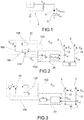
- FIG. 3 shows a block diagram of the control circuit of the invention in an embodiment variant.
- the adjustable power supply 10' has a non-adjustable feedback block 108', but the adjustment terminal 104, connected to the output of the non-linear feedback network 20, acts on a reference voltage setting network that defines the value of the reference voltage Vref internal to the power supply.
- Figure 4 is a circuit diagram of an exemplary embodiment of the circuit architecture in figure 2 .
- the current control device 14 is implemented with a current controller, which requires a minimum voltage drop to ensure the regulation of the current.
- the non-linear feedback network 20 comprises a feedback selector circuit having a control node 202 operatively connected to the control terminal 104, an upper branch 204 that connects the control node to the output terminal 102 of the adjustable power supply 10 by means of a feedback impedance 204', for example with a resistive element, a lower branch 206 that connects the control node 202 to ground by means of a capacitor 206', and at least one intermediate branch 208 connecting the control node 202 to the current controller 14 by means of at least one diode 208'.
- diode 208' has its anode connected to the control node 202 and the cathode connected to the current controller 14 terminal which is at the voltage Vreg to be stabilized.
- the feedback selector circuit thus defined implements two circuit paths for the feedback current, which are activated selectively as a function of the value Vreg, as will be described hereinafter.
- the adjustable feedback block 108 of the adjustable power supply 10 comprises a voltage divider 110.
- This voltage divider 110 comprises a first resistor 112 between a feedback terminal 114 and ground, a second resistor 116 between the output terminal 102 of the adjustable power supply and the feedback terminal 114, and a third resistor 118 also connected between the output terminal 102 and the feedback terminal 114, but by means of an electrically adjustable impedance element 120, such as a MOS-FET, the gate terminal of which coincides with, or is operatively connected to, the feedback terminal 104.
- an electrically adjustable impedance element 120 such as a MOS-FET
- the response dynamic of the feedback network 20 is in this case given by the time constant RC, where R is the resistance of the resistive element 204' and C is the capacitance of capacitor 206'.
- Vreg is thus stabilized around a set-point value (Vout0, Vreg0), in which the current from the upper branch 204 of the feedback selector circuit circulates mainly in the intermediate branch 208 and only a fraction thereof flows through capacitor 206', in order to compensate for parasitic losses.
- the level of voltage Vsw of the control node 202 therefore remains constant.
- Vout0, Vreg0 Vout ⁇ Vd
- Vref is the voltage on the feedback terminal 114 and Vd is the forward voltage drop on the lighting source 3.
- the balance point is defined by the value of the gate-source threshold voltage V GS_TH .
- the adjustment of the voltage drop Vreg at the terminals of the current control device 14 is carried out continuously due to the intrinsic characteristic of the field effect transistor MOS-FET or BJT (the resistance of the transistor, in fact, varies continuously as a function of the voltage applied between gate and source). Consequently, the second impedance 116 will always be in parallel (or, in an embodiment variant, in series) to the electrically adjustable impedance element 120.
- the third impedance 118 could also not be present.
- the control circuit can be adequately sensitive to the intrinsically slow decrease of the voltage drop on the lighting sources, for example due to ageing and temperature rise, and insensitive to the rapid rising edges of voltage Vreg at the terminals of the current control device, which are generated when a lighting source is temporarily turned off, for example in control modulation situations PWM, or during the generation of an animation sequence.
- a more stable output supply voltage Vout can also be obtained during a modulation PWM or an animation, resulting in improved electromagnetic performance, especially when using cables to control the lighting sources.
- the parameters of the control circuit in particular of the non-linear feedback network, may be set so as to achieve fast dynamics in response to an increase of the Vreg and slower dynamics in response to a lowering of the Vreg.
- Figure 6 shows a circuitry implementation similar to that described with reference to figure 4 , in which multiple lighting branches 12 are powered.
- the non-linear feedback network 20 is modified by providing a diode 208' for each lighting branch 12.
- this architecture also represents a relatively cost-effective and reliable solution.
- the design of the circuit stability is facilitated by the fact that the feedback network does not interact significantly with the intrinsic feedback of the power supply.
- an external feedback network which acts on the adjustable feedback block of the power supply with a slower time constant than that of the feedback loop of the power supply actually decouples the lighting branches from the feedback block of the power supply, thus allowing the lighting sources to be considered as a load rather than a part of the feedback path.
- the output supply voltage Vout is set according to the value of Vreg, such an architecture is able to also control additional loads, without affecting the current flow of the lighting source. Therefore, the same supply voltage Vout can be used as input to additional circuits (e.g., voltage controllers).
- additional circuits e.g., voltage controllers
- control circuit therefore comprises any decoupling tripole having a transfer function that varies in an electrically controlled, linear or non-linear manner, as a function of an input voltage or current present on the current control device and which acts on the feedback block of the adjustable power supply.
- Such a control circuit corresponds to that shown in the block diagram in figure 2 and to a circuit implementation thereof shown in figure 4 , where the feedback block consists of the output voltage divider of the adjustable power supply, formed by resistors and an electrically adjustable impedance element.
- the non-linear feedback network 20 can be replaced by another feedback network, also linear, for example implemented with amplifiers, provided that its output is connected to the feedback block of the power supply.
- Figure 7 shows a circuit implementation of the control circuit architecture in figure 3 . Also in this case, the non-linear feedback network 20 is implemented with the feedback selector circuit described above.
- the adjustment terminal 104 in output to the non-linear feedback network acts on a reference voltage setting network 30 defining the reference voltage internal to the adjustable power supply 10.
- this setting network 30 comprises a constant resistor 302 and an electrically adjustable impedance element 304, 306 connected mutually in parallel.
- this electrically adjustable impedance element 304, 306 comprises a constant resistance element 304 placed in series to a transistor 306, for example a MOS-FET, the gate terminal whereof coincides with, or is connected to, the adjustment terminal 104, so as to be driven by the feedback network 20.
- the impedance value of the electrically adjustable impedance element 306 varies, thereby modifying the overall impedance value of the setting circuit 30 and therefore the value of the reference voltage internal to the power supply.
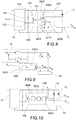
- Figure 8 shows a circuit diagram similar to that in figure 4 , but in which the non-linear feedback network 200 is implemented with active components.
- the non-linear feedback network 200 comprises a control switch 2002, in the example implemented with a P-MOS, having its gate terminal connected to the output terminal 102 of the adjustable power supply 10 by means of a resistive element 2004, and connected to the current control device 14, the source terminal operatively connected to the adjustment terminal 104, and the drain terminal connected to ground by means of a resistor 2006.
- a control switch 2002 in the example implemented with a P-MOS, having its gate terminal connected to the output terminal 102 of the adjustable power supply 10 by means of a resistive element 2004, and connected to the current control device 14, the source terminal operatively connected to the adjustment terminal 104, and the drain terminal connected to ground by means of a resistor 2006.
- a capacitor 2008 is connected between the source terminal and the drain terminal.
- the feedback network 200 further comprises an operational amplifier 2010 having the inverting input terminal connected to the drain terminal, the non-inverting input terminal to a reference voltage V, and the output terminal connected to the source terminal.
- the P-MOS When the voltage at the terminals of the current control device exceeds the voltage value given by the difference between the voltage of the source terminal and the gate-source threshold voltage of the P-MOS, the P-MOS is cut off and the output of the operational amplifier, and thus the value of the control node voltage, varies according to the time constant RC given by the resistor connected between the inverting terminal of the amplifier and ground, and by the capacitor placed between drain and source. Due to the action of the control signal present on the control node, the value of the output supply voltage also rapidly decreases according to such a dynamic.
- Figure 9 shows a block diagram similar to that in figure 2 , thus with a non-linear feedback network acting on an adjustable feedback block 108 of the adjustable power supply 10, where the non-linear feedback network, indicated with 300, is based on a microprocessor 3002 and on a detection network 3004 of the voltage drops Vregk at the terminals of the current control device 14.
- FIG. 10 A possible implementation of the diagram in figure 9 is shown in figure 10 , in which a multichannel analog-digital converter ADC 3004 is used to detect the multiple signals Vregk and Vout, while a digital-analog converter DAC 3006 is used to generate the adjustment signal Vsw.
- ADC 3004 is used to detect the multiple signals Vregk and Vout
- DAC 3006 is used to generate the adjustment signal Vsw.
- the non-linear feedback is implemented by the internal code of microprocessor 3002, which generates the adjustment signal Vsw as a function of the detected signals Vregk and Vout.
- an object of the present invention is also an automotive headlight 500 provided with a control circuit 600 of lighting sources, such as LED or OLED.
- the feedback selector circuit that implements the non-linear feedback network may be connected to a voltage different from the supply voltage Vout, provided that the voltage on the resistive element of the selector circuit is greater than the voltage of the control node.
Landscapes
- Circuit Arrangement For Electric Light Sources In General (AREA)
- Lighting Device Outwards From Vehicle And Optical Signal (AREA)
Applications Claiming Priority (1)
| Application Number | Priority Date | Filing Date | Title |
|---|---|---|---|
| IT102016000132337A IT201600132337A1 (it) | 2016-12-29 | 2016-12-29 | Circuito di pilotaggio di sorgenti di illuminazione, in particolare per un fanale automobilistico |
Publications (2)
| Publication Number | Publication Date |
|---|---|
| EP3344012A1 true EP3344012A1 (de) | 2018-07-04 |
| EP3344012B1 EP3344012B1 (de) | 2023-07-05 |
Family
ID=58609917
Family Applications (1)
| Application Number | Title | Priority Date | Filing Date |
|---|---|---|---|
| EP17210912.6A Active EP3344012B1 (de) | 2016-12-29 | 2017-12-28 | Treiberschaltung für lichtquellen, insbesondere für ein fahrzeuglicht |
Country Status (4)
| Country | Link |
|---|---|
| EP (1) | EP3344012B1 (de) |
| ES (1) | ES2959197T3 (de) |
| IT (1) | IT201600132337A1 (de) |
| PL (1) | PL3344012T3 (de) |
Cited By (1)
| Publication number | Priority date | Publication date | Assignee | Title |
|---|---|---|---|---|
| EP3641500A1 (de) * | 2018-10-16 | 2020-04-22 | Valeo Iluminacion | Beleuchtungssystem zur spannungsregelung in fahrzeugscheinwerfer |
Citations (5)
| Publication number | Priority date | Publication date | Assignee | Title |
|---|---|---|---|---|
| US20060108933A1 (en) * | 2004-11-19 | 2006-05-25 | Sheng-Feng Chen | Light emitted diode driving apparatus |
| US20100134040A1 (en) * | 2008-12-03 | 2010-06-03 | Freescale Semiconductor, Inc. | Led driver with precharge and track/hold |
| US20100327835A1 (en) * | 2009-06-26 | 2010-12-30 | Intersil Americas Inc. | Integrator for providing overshoot protection and light switching mode during non-zero load condition for an led driver circuitry |
| WO2013076685A1 (en) * | 2011-11-23 | 2013-05-30 | Automotive Lighting Italia S.P.A. A Socio Unico | Led driver circuit, driving method and vehicle light |
| US20160302270A1 (en) * | 2015-02-27 | 2016-10-13 | Diodes Incorporated | Power optimization for linear regulator |
Family Cites Families (2)
| Publication number | Priority date | Publication date | Assignee | Title |
|---|---|---|---|---|
| US20070273681A1 (en) * | 2006-05-24 | 2007-11-29 | Mayell Robert J | Method and apparatus to power light emitting diode arrays |
| KR101822889B1 (ko) * | 2016-06-14 | 2018-03-08 | 엘지전자 주식회사 | 리어 콤비네이션 램프의 입력 전압 안정화 회로, 리어 콤비네이션 램프 및 차량 |
-
2016
- 2016-12-29 IT IT102016000132337A patent/IT201600132337A1/it unknown
-
2017
- 2017-12-28 PL PL17210912.6T patent/PL3344012T3/pl unknown
- 2017-12-28 EP EP17210912.6A patent/EP3344012B1/de active Active
- 2017-12-28 ES ES17210912T patent/ES2959197T3/es active Active
Patent Citations (5)
| Publication number | Priority date | Publication date | Assignee | Title |
|---|---|---|---|---|
| US20060108933A1 (en) * | 2004-11-19 | 2006-05-25 | Sheng-Feng Chen | Light emitted diode driving apparatus |
| US20100134040A1 (en) * | 2008-12-03 | 2010-06-03 | Freescale Semiconductor, Inc. | Led driver with precharge and track/hold |
| US20100327835A1 (en) * | 2009-06-26 | 2010-12-30 | Intersil Americas Inc. | Integrator for providing overshoot protection and light switching mode during non-zero load condition for an led driver circuitry |
| WO2013076685A1 (en) * | 2011-11-23 | 2013-05-30 | Automotive Lighting Italia S.P.A. A Socio Unico | Led driver circuit, driving method and vehicle light |
| US20160302270A1 (en) * | 2015-02-27 | 2016-10-13 | Diodes Incorporated | Power optimization for linear regulator |
Cited By (1)
| Publication number | Priority date | Publication date | Assignee | Title |
|---|---|---|---|---|
| EP3641500A1 (de) * | 2018-10-16 | 2020-04-22 | Valeo Iluminacion | Beleuchtungssystem zur spannungsregelung in fahrzeugscheinwerfer |
Also Published As
| Publication number | Publication date |
|---|---|
| IT201600132337A1 (it) | 2018-06-29 |
| ES2959197T3 (es) | 2024-02-21 |
| EP3344012B1 (de) | 2023-07-05 |
| PL3344012T3 (pl) | 2024-01-22 |
Similar Documents
| Publication | Publication Date | Title |
|---|---|---|
| US7948299B2 (en) | Power supply apparatus | |
| US7705543B2 (en) | Supply device of circuit branches with LED diodes | |
| US9265109B2 (en) | Light source control device | |
| US9768687B2 (en) | Step-down DC/DC converter | |
| US8242756B2 (en) | Load driving device and portable apparatus utilizing such driving device | |
| US7679351B2 (en) | Power supply apparatus | |
| US9337727B2 (en) | Circuitry to control a switching regulator | |
| US6184663B1 (en) | Apparatus for driving electric load | |
| US6608520B1 (en) | Regulator circuit | |
| US20100213845A1 (en) | Led driving device with variable light intensity | |
| US7898299B2 (en) | Current sense amplifier | |
| EP3344013A1 (de) | Treiberschaltung für lichtquellen, insbesondere für ein fahrzeuglicht | |
| US20060012932A1 (en) | Overcurrent protection circuit | |
| US20010048295A1 (en) | Power supply device | |
| US20170351285A1 (en) | Linear power supply and electronic apparatus using same | |
| US11031771B2 (en) | Power supply control apparatus | |
| US4556838A (en) | Electronic switch | |
| US10562438B2 (en) | Light-emitting element driving semiconductor integrated circuit, light-emitting element driving device, light-emitting device, and vehicle | |
| EP3344012A1 (de) | Treiberschaltung für lichtquellen, insbesondere für ein fahrzeuglicht | |
| US10411600B1 (en) | Apparatus and methods for converter mode and load configuration control | |
| US7148668B1 (en) | Completely isolated synchronous boost DC-to-DC switching regulator | |
| JP3012616B1 (ja) | 過電圧保護回路 | |
| US5977755A (en) | Constant-voltage power supply circuit | |
| US6801063B1 (en) | Charge compensated bootstrap driving circuit | |
| JP2005110356A (ja) | 負荷駆動装置及び携帯機器 |
Legal Events
| Date | Code | Title | Description |
|---|---|---|---|
| PUAI | Public reference made under article 153(3) epc to a published international application that has entered the european phase |
Free format text: ORIGINAL CODE: 0009012 |
|
| STAA | Information on the status of an ep patent application or granted ep patent |
Free format text: STATUS: THE APPLICATION HAS BEEN PUBLISHED |
|
| AK | Designated contracting states |
Kind code of ref document: A1 Designated state(s): AL AT BE BG CH CY CZ DE DK EE ES FI FR GB GR HR HU IE IS IT LI LT LU LV MC MK MT NL NO PL PT RO RS SE SI SK SM TR |
|
| AX | Request for extension of the european patent |
Extension state: BA ME |
|
| STAA | Information on the status of an ep patent application or granted ep patent |
Free format text: STATUS: REQUEST FOR EXAMINATION WAS MADE |
|
| 17P | Request for examination filed |
Effective date: 20181214 |
|
| RBV | Designated contracting states (corrected) |
Designated state(s): AL AT BE BG CH CY CZ DE DK EE ES FI FR GB GR HR HU IE IS IT LI LT LU LV MC MK MT NL NO PL PT RO RS SE SI SK SM TR |
|
| STAA | Information on the status of an ep patent application or granted ep patent |
Free format text: STATUS: EXAMINATION IS IN PROGRESS |
|
| STAA | Information on the status of an ep patent application or granted ep patent |
Free format text: STATUS: EXAMINATION IS IN PROGRESS |
|
| 17Q | First examination report despatched |
Effective date: 20201110 |
|
| STAA | Information on the status of an ep patent application or granted ep patent |
Free format text: STATUS: EXAMINATION IS IN PROGRESS |
|
| RAP3 | Party data changed (applicant data changed or rights of an application transferred) |
Owner name: MARELLI AUTOMOTIVE LIGHTING ITALY S.P.A. |
|
| REG | Reference to a national code |
Ref country code: DE Ref legal event code: R079 Ref document number: 602017070889 Country of ref document: DE Free format text: PREVIOUS MAIN CLASS: H05B0033080000 Ipc: H05B0045100000 Ref legal event code: R079 Free format text: PREVIOUS MAIN CLASS: H05B0033080000 |
|
| RIC1 | Information provided on ipc code assigned before grant |
Ipc: B60Q 1/04 20060101ALN20221213BHEP Ipc: H05B 45/395 20200101ALI20221213BHEP Ipc: H05B 45/347 20200101ALI20221213BHEP Ipc: H05B 45/46 20200101ALI20221213BHEP Ipc: H05B 45/10 20200101AFI20221213BHEP |
|
| GRAP | Despatch of communication of intention to grant a patent |
Free format text: ORIGINAL CODE: EPIDOSNIGR1 |
|
| STAA | Information on the status of an ep patent application or granted ep patent |
Free format text: STATUS: GRANT OF PATENT IS INTENDED |
|
| INTG | Intention to grant announced |
Effective date: 20230124 |
|
| GRAS | Grant fee paid |
Free format text: ORIGINAL CODE: EPIDOSNIGR3 |
|
| GRAA | (expected) grant |
Free format text: ORIGINAL CODE: 0009210 |
|
| STAA | Information on the status of an ep patent application or granted ep patent |
Free format text: STATUS: THE PATENT HAS BEEN GRANTED |
|
| AK | Designated contracting states |
Kind code of ref document: B1 Designated state(s): AL AT BE BG CH CY CZ DE DK EE ES FI FR GB GR HR HU IE IS IT LI LT LU LV MC MK MT NL NO PL PT RO RS SE SI SK SM TR |
|
| P01 | Opt-out of the competence of the unified patent court (upc) registered |
Effective date: 20230526 |
|
| REG | Reference to a national code |
Ref country code: CH Ref legal event code: EP |
|
| REG | Reference to a national code |
Ref country code: AT Ref legal event code: REF Ref document number: 1586021 Country of ref document: AT Kind code of ref document: T Effective date: 20230715 |
|
| REG | Reference to a national code |
Ref country code: DE Ref legal event code: R096 Ref document number: 602017070889 Country of ref document: DE |
|
| REG | Reference to a national code |
Ref country code: IE Ref legal event code: FG4D |
|
| REG | Reference to a national code |
Ref country code: LT Ref legal event code: MG9D |
|
| REG | Reference to a national code |
Ref country code: NL Ref legal event code: MP Effective date: 20230705 |
|
| REG | Reference to a national code |
Ref country code: AT Ref legal event code: MK05 Ref document number: 1586021 Country of ref document: AT Kind code of ref document: T Effective date: 20230705 |
|
| PG25 | Lapsed in a contracting state [announced via postgrant information from national office to epo] |
Ref country code: NL Free format text: LAPSE BECAUSE OF FAILURE TO SUBMIT A TRANSLATION OF THE DESCRIPTION OR TO PAY THE FEE WITHIN THE PRESCRIBED TIME-LIMIT Effective date: 20230705 |
|
| PG25 | Lapsed in a contracting state [announced via postgrant information from national office to epo] |
Ref country code: GR Free format text: LAPSE BECAUSE OF FAILURE TO SUBMIT A TRANSLATION OF THE DESCRIPTION OR TO PAY THE FEE WITHIN THE PRESCRIBED TIME-LIMIT Effective date: 20231006 |
|
| PGFP | Annual fee paid to national office [announced via postgrant information from national office to epo] |
Ref country code: GB Payment date: 20231121 Year of fee payment: 7 |
|
| PG25 | Lapsed in a contracting state [announced via postgrant information from national office to epo] |
Ref country code: IS Free format text: LAPSE BECAUSE OF FAILURE TO SUBMIT A TRANSLATION OF THE DESCRIPTION OR TO PAY THE FEE WITHIN THE PRESCRIBED TIME-LIMIT Effective date: 20231105 |
|
| PG25 | Lapsed in a contracting state [announced via postgrant information from national office to epo] |
Ref country code: SE Free format text: LAPSE BECAUSE OF FAILURE TO SUBMIT A TRANSLATION OF THE DESCRIPTION OR TO PAY THE FEE WITHIN THE PRESCRIBED TIME-LIMIT Effective date: 20230705 Ref country code: RS Free format text: LAPSE BECAUSE OF FAILURE TO SUBMIT A TRANSLATION OF THE DESCRIPTION OR TO PAY THE FEE WITHIN THE PRESCRIBED TIME-LIMIT Effective date: 20230705 Ref country code: PT Free format text: LAPSE BECAUSE OF FAILURE TO SUBMIT A TRANSLATION OF THE DESCRIPTION OR TO PAY THE FEE WITHIN THE PRESCRIBED TIME-LIMIT Effective date: 20231106 Ref country code: NO Free format text: LAPSE BECAUSE OF FAILURE TO SUBMIT A TRANSLATION OF THE DESCRIPTION OR TO PAY THE FEE WITHIN THE PRESCRIBED TIME-LIMIT Effective date: 20231005 Ref country code: LV Free format text: LAPSE BECAUSE OF FAILURE TO SUBMIT A TRANSLATION OF THE DESCRIPTION OR TO PAY THE FEE WITHIN THE PRESCRIBED TIME-LIMIT Effective date: 20230705 Ref country code: LT Free format text: LAPSE BECAUSE OF FAILURE TO SUBMIT A TRANSLATION OF THE DESCRIPTION OR TO PAY THE FEE WITHIN THE PRESCRIBED TIME-LIMIT Effective date: 20230705 Ref country code: IS Free format text: LAPSE BECAUSE OF FAILURE TO SUBMIT A TRANSLATION OF THE DESCRIPTION OR TO PAY THE FEE WITHIN THE PRESCRIBED TIME-LIMIT Effective date: 20231105 Ref country code: HR Free format text: LAPSE BECAUSE OF FAILURE TO SUBMIT A TRANSLATION OF THE DESCRIPTION OR TO PAY THE FEE WITHIN THE PRESCRIBED TIME-LIMIT Effective date: 20230705 Ref country code: GR Free format text: LAPSE BECAUSE OF FAILURE TO SUBMIT A TRANSLATION OF THE DESCRIPTION OR TO PAY THE FEE WITHIN THE PRESCRIBED TIME-LIMIT Effective date: 20231006 Ref country code: FI Free format text: LAPSE BECAUSE OF FAILURE TO SUBMIT A TRANSLATION OF THE DESCRIPTION OR TO PAY THE FEE WITHIN THE PRESCRIBED TIME-LIMIT Effective date: 20230705 Ref country code: AT Free format text: LAPSE BECAUSE OF FAILURE TO SUBMIT A TRANSLATION OF THE DESCRIPTION OR TO PAY THE FEE WITHIN THE PRESCRIBED TIME-LIMIT Effective date: 20230705 |
|
| PGFP | Annual fee paid to national office [announced via postgrant information from national office to epo] |
Ref country code: TR Payment date: 20231129 Year of fee payment: 7 Ref country code: FR Payment date: 20231122 Year of fee payment: 7 Ref country code: DE Payment date: 20231121 Year of fee payment: 7 Ref country code: CZ Payment date: 20231124 Year of fee payment: 7 |
|
| REG | Reference to a national code |
Ref country code: ES Ref legal event code: FG2A Ref document number: 2959197 Country of ref document: ES Kind code of ref document: T3 Effective date: 20240221 |
|
| REG | Reference to a national code |
Ref country code: DE Ref legal event code: R097 Ref document number: 602017070889 Country of ref document: DE |
|
| PGFP | Annual fee paid to national office [announced via postgrant information from national office to epo] |
Ref country code: ES Payment date: 20240102 Year of fee payment: 7 |
|
| PG25 | Lapsed in a contracting state [announced via postgrant information from national office to epo] |
Ref country code: SM Free format text: LAPSE BECAUSE OF FAILURE TO SUBMIT A TRANSLATION OF THE DESCRIPTION OR TO PAY THE FEE WITHIN THE PRESCRIBED TIME-LIMIT Effective date: 20230705 Ref country code: RO Free format text: LAPSE BECAUSE OF FAILURE TO SUBMIT A TRANSLATION OF THE DESCRIPTION OR TO PAY THE FEE WITHIN THE PRESCRIBED TIME-LIMIT Effective date: 20230705 Ref country code: EE Free format text: LAPSE BECAUSE OF FAILURE TO SUBMIT A TRANSLATION OF THE DESCRIPTION OR TO PAY THE FEE WITHIN THE PRESCRIBED TIME-LIMIT Effective date: 20230705 Ref country code: DK Free format text: LAPSE BECAUSE OF FAILURE TO SUBMIT A TRANSLATION OF THE DESCRIPTION OR TO PAY THE FEE WITHIN THE PRESCRIBED TIME-LIMIT Effective date: 20230705 Ref country code: SK Free format text: LAPSE BECAUSE OF FAILURE TO SUBMIT A TRANSLATION OF THE DESCRIPTION OR TO PAY THE FEE WITHIN THE PRESCRIBED TIME-LIMIT Effective date: 20230705 |
|
| PLBE | No opposition filed within time limit |
Free format text: ORIGINAL CODE: 0009261 |
|
| STAA | Information on the status of an ep patent application or granted ep patent |
Free format text: STATUS: NO OPPOSITION FILED WITHIN TIME LIMIT |