EP3343897B1 - Camera and method of producing color images - Google Patents
Camera and method of producing color images Download PDFInfo
- Publication number
- EP3343897B1 EP3343897B1 EP17209246.2A EP17209246A EP3343897B1 EP 3343897 B1 EP3343897 B1 EP 3343897B1 EP 17209246 A EP17209246 A EP 17209246A EP 3343897 B1 EP3343897 B1 EP 3343897B1
- Authority
- EP
- European Patent Office
- Prior art keywords
- radiation
- pixels
- filter
- camera
- pairs
- Prior art date
- Legal status (The legal status is an assumption and is not a legal conclusion. Google has not performed a legal analysis and makes no representation as to the accuracy of the status listed.)
- Active
Links
- 238000000034 method Methods 0.000 title claims description 17
- 230000005855 radiation Effects 0.000 claims description 142
- 230000000903 blocking effect Effects 0.000 claims description 11
- 238000012545 processing Methods 0.000 claims description 10
- 230000003595 spectral effect Effects 0.000 description 22
- 238000013461 design Methods 0.000 description 7
- 238000000576 coating method Methods 0.000 description 5
- 238000002329 infrared spectrum Methods 0.000 description 5
- 238000011156 evaluation Methods 0.000 description 4
- 230000004044 response Effects 0.000 description 4
- 230000000295 complement effect Effects 0.000 description 3
- 230000003287 optical effect Effects 0.000 description 3
- 238000001228 spectrum Methods 0.000 description 3
- 230000000007 visual effect Effects 0.000 description 3
- 230000009286 beneficial effect Effects 0.000 description 2
- 239000003086 colorant Substances 0.000 description 2
- 238000001514 detection method Methods 0.000 description 2
- 230000009977 dual effect Effects 0.000 description 2
- 238000003384 imaging method Methods 0.000 description 2
- 239000000463 material Substances 0.000 description 2
- 239000000203 mixture Substances 0.000 description 2
- 238000012986 modification Methods 0.000 description 2
- 230000004048 modification Effects 0.000 description 2
- 238000012544 monitoring process Methods 0.000 description 2
- 230000008569 process Effects 0.000 description 2
- 238000000926 separation method Methods 0.000 description 2
- 230000004075 alteration Effects 0.000 description 1
- 230000008901 benefit Effects 0.000 description 1
- 230000003139 buffering effect Effects 0.000 description 1
- 238000012937 correction Methods 0.000 description 1
- 238000010586 diagram Methods 0.000 description 1
- 230000000694 effects Effects 0.000 description 1
- 238000001914 filtration Methods 0.000 description 1
- 230000006870 function Effects 0.000 description 1
- 239000011521 glass Substances 0.000 description 1
- 238000010348 incorporation Methods 0.000 description 1
- 238000004519 manufacturing process Methods 0.000 description 1
- 238000002156 mixing Methods 0.000 description 1
- 239000004033 plastic Substances 0.000 description 1
- 229920003023 plastic Polymers 0.000 description 1
- 229920006395 saturated elastomer Polymers 0.000 description 1
- 239000007787 solid Substances 0.000 description 1
- 238000001429 visible spectrum Methods 0.000 description 1
Images


Classifications
-
- H—ELECTRICITY
- H04—ELECTRIC COMMUNICATION TECHNIQUE
- H04N—PICTORIAL COMMUNICATION, e.g. TELEVISION
- H04N23/00—Cameras or camera modules comprising electronic image sensors; Control thereof
- H04N23/10—Cameras or camera modules comprising electronic image sensors; Control thereof for generating image signals from different wavelengths
- H04N23/12—Cameras or camera modules comprising electronic image sensors; Control thereof for generating image signals from different wavelengths with one sensor only
-
- G—PHYSICS
- G03—PHOTOGRAPHY; CINEMATOGRAPHY; ANALOGOUS TECHNIQUES USING WAVES OTHER THAN OPTICAL WAVES; ELECTROGRAPHY; HOLOGRAPHY
- G03B—APPARATUS OR ARRANGEMENTS FOR TAKING PHOTOGRAPHS OR FOR PROJECTING OR VIEWING THEM; APPARATUS OR ARRANGEMENTS EMPLOYING ANALOGOUS TECHNIQUES USING WAVES OTHER THAN OPTICAL WAVES; ACCESSORIES THEREFOR
- G03B7/00—Control of exposure by setting shutters, diaphragms or filters, separately or conjointly
-
- G—PHYSICS
- G02—OPTICS
- G02B—OPTICAL ELEMENTS, SYSTEMS OR APPARATUS
- G02B5/00—Optical elements other than lenses
- G02B5/20—Filters
- G02B5/201—Filters in the form of arrays
-
- G—PHYSICS
- G02—OPTICS
- G02B—OPTICAL ELEMENTS, SYSTEMS OR APPARATUS
- G02B5/00—Optical elements other than lenses
- G02B5/20—Filters
- G02B5/208—Filters for use with infrared or ultraviolet radiation, e.g. for separating visible light from infrared and/or ultraviolet radiation
-
- G—PHYSICS
- G02—OPTICS
- G02B—OPTICAL ELEMENTS, SYSTEMS OR APPARATUS
- G02B7/00—Mountings, adjusting means, or light-tight connections, for optical elements
- G02B7/006—Filter holders
-
- G—PHYSICS
- G03—PHOTOGRAPHY; CINEMATOGRAPHY; ANALOGOUS TECHNIQUES USING WAVES OTHER THAN OPTICAL WAVES; ELECTROGRAPHY; HOLOGRAPHY
- G03B—APPARATUS OR ARRANGEMENTS FOR TAKING PHOTOGRAPHS OR FOR PROJECTING OR VIEWING THEM; APPARATUS OR ARRANGEMENTS EMPLOYING ANALOGOUS TECHNIQUES USING WAVES OTHER THAN OPTICAL WAVES; ACCESSORIES THEREFOR
- G03B11/00—Filters or other obturators specially adapted for photographic purposes
-
- H—ELECTRICITY
- H04—ELECTRIC COMMUNICATION TECHNIQUE
- H04N—PICTORIAL COMMUNICATION, e.g. TELEVISION
- H04N23/00—Cameras or camera modules comprising electronic image sensors; Control thereof
- H04N23/10—Cameras or camera modules comprising electronic image sensors; Control thereof for generating image signals from different wavelengths
- H04N23/11—Cameras or camera modules comprising electronic image sensors; Control thereof for generating image signals from different wavelengths for generating image signals from visible and infrared light wavelengths
-
- H—ELECTRICITY
- H04—ELECTRIC COMMUNICATION TECHNIQUE
- H04N—PICTORIAL COMMUNICATION, e.g. TELEVISION
- H04N23/00—Cameras or camera modules comprising electronic image sensors; Control thereof
- H04N23/50—Constructional details
- H04N23/55—Optical parts specially adapted for electronic image sensors; Mounting thereof
-
- H—ELECTRICITY
- H04—ELECTRIC COMMUNICATION TECHNIQUE
- H04N—PICTORIAL COMMUNICATION, e.g. TELEVISION
- H04N25/00—Circuitry of solid-state image sensors [SSIS]; Control thereof
- H04N25/70—SSIS architectures; Circuits associated therewith
- H04N25/702—SSIS architectures characterised by non-identical, non-equidistant or non-planar pixel layout
Definitions
- the present invention relates to producing color images, and especially a camera design allowing for producing color images under low light conditions.
- Image sensors used in digital cameras have a spectral response with a non-negligible component in the infrared, IR. This results in opportunities as well as challenges.
- Low-light condition may also be defined as conditions where the amount of visible light and IR-radiation are comparable, hence, low-light condition may also be referred to as a mixed light condition.
- incoming radiation from the IR portion of the spectrum.
- the IR radiation will not contain any color information, and instead of performing a color separation, the only parameter is the intensity of the incoming radiation, which may be presented as a black and white intensity image (or with any desirable color scale).
- a challenge is found during day-time imaging, where the addition of an IR-component may distort the color balance in images captured using a digital camera. In some situations, some or all pixels of the image sensor may even be completely saturated by the infrared component.
- a way of maintaining the beneficial effects while suppressing the less beneficial effects is to add a movable IR-cut filter in the beam path in front of the image sensor.
- the IR-cut filter may be used during daylight conditions, enabling acquisition of color images. Pixels of the image sensor will then operate in a first manner, where the incident light is divided into colors and detected as a charge on individual photodetectors thus enabling color separation. The IR-cut filter will be removed during night time, or in low-light conditions allowing IR-radiation to reach the image sensor. Pixels of the image sensor will then operate in a second manner, where the only parameter measured by the pixels is the intensity of the incoming radiation. Hence, intensity based images may be captured, and presented in black and white.
- US 2011/228145 A1 is disclosing a camera comprising an IR-filter that is partially blocking the optical path of the light entering the camera. In order to determine the amount of IR-light the filter has to be removed from the optical path.
- JP 2003 264842 A also discloses a camera which can detect the amount of IR-light entering the camera, in this case certain pixels are masked with an IR filter.
- a camera comprising: an aperture; an image sensor comprising a plurality of pairs of pixels in which pair: a first pixel is configured such that it detects radiation which has entered the camera through the aperture and travelled from the aperture to the image sensor via a first radiation path, and a second pixel is configured such that it detects radiation which has entered the camera through the aperture and travelled from the aperture to the image sensor via a second radiation path, the second radiation path being different from the first radiation path; and a filter arranged in, or in the vicinity of, the aperture, wherein the filter comprises a first portion configured to block IR-radiation or visible light and a second portion configured to be transparent to wavelengths that are blocked by the first portion, wherein the filter is arranged such that radiation passing the first portion travels to the first pixels of the plurality of pairs of pixels, and such that radiation passing the second portion travels to the second pixels of the plurality of pairs of pixels.
- IR-radiation may be determined by comparing radiation detected by the first and second pixels in each pair of first and second pixels, and compensating for that IR portion.
- a color image may be produced by determining the IR-portion of radiation detected by the image sensor. In this way, a true color representation may be obtained, even though the imaged scene contains IR-radiation which is captured by the image sensor.
- radiation is to be construed as radiation comprising spectral components both in the infrared spectral range and in the visible light spectral range.
- the first portion of the filter may be configured to block IR-radiation.
- the first portion of the filter may be configured to block visible light.
- the second portion of the filter may be configured to be transparent to both IR-radiation and visible light.
- the first portion of the filter may be configured to block IR-radiation and the second portion of the filter may be configured to block visible light.
- the filter may be fixedly positioned in, or in the vicinity of, the aperture.
- a simple camera with very few movable parts may thus be provided.
- the filter does not have to be (often cannot be) exactly in the aperture plane, but as long as it is close enough, it does not matter which side of the aperture it is.
- the filter has to be close to the aperture. It does not have to be (often cannot be) exactly in the aperture plane, but as long as it is close enough, it does not matter which side of the aperture it is.
- the filter may movable such that it may be positioned in and retracted from the first and second radiation paths.
- a day mode wherein the filter with the first and second portions are used for calculating a proportion of IR-radiation in the scene based on an amount of radiation detected by each of the first and second pixels of the plurality of pairs of pixels and a night mode wherein the filter is removed, and the full spectral response of the image sensor is used for producing black and white images.
- the filter is useful when the scene comprises both visible light and IR-radiation. In these situations, it is possible to compensate for the IR-radiation and get good color fidelity. This is particularly useful in mixed light (low light, such as at dusk and dawn), where in implementation of today a switch to only registering the amount of radiation removing the IR cut filter is used. This is needed when the visible light level gets too low. In day light or good light, the IR-radiation is not needed, because there is plenty of visible light.
- the camera set up according to the present invention makes it possible to compensate for the IR-radiation. In traditional monitoring cameras, this is when the IR cut filter is inserted.
- the portioning of the filter may be aligned with the first and second pixels such that: IR-radiation will not reach the first pixels in the pair of pixels, and IR-radiation will reach the second pixels in the pair of pixels.
- Each pixel of the image sensor may belong to a respective pair of pixels.
- the image sensor may be configured to, upon the camera being exposed to radiation comprising both visible light and IR-radiation, register a value indicative of an amount of radiation reaching each of the plurality of pairs of pixels.
- the camera may further comprise a processing unit configured to: determine, for each of the first pixels of the plurality of pairs of pixels, a value indicative of a first amount of radiation detected by the respective first pixel, determine, for each of the second pixels of the plurality of pairs of pixels, a value indicative of a second amount of radiation detected by the respective second pixel, calculate a proportion of IR-radiation in the scene based on the first and second amount of radiation determined for each of the first and second pixels of the plurality of pairs of pixels, and produce a color image of the scene by compensating for an IR-contribution in an image captured by the camera based on the calculated proportion of IR-radiation.
- a method of producing a color image of a scene captured by a camera exposed to radiation comprising both visible light and IR-radiation comprises: detecting a value indicative of an amount of radiation in each of a plurality of pairs of pixels, wherein each pair comprises a first pixel and a second pixel, determining, for each of the first pixels of the plurality of pairs of pixels, a value indicative of a first amount of radiation detected by the respective first pixel, determining for each of the second pixels of the plurality of pairs of pixels a value indicative of a second amount of radiation detected by the respective second pixel, calculating a proportion of IR-radiation in the scene based on the first and second amount of radiation determined for each of the first and second pixels of the plurality of pairs of pixels, and producing the color image of the scene by compensating for an IR-contribution in an image captured by the camera based on the calculated proportion of IR-radiation.
- the method may further comprise blocking IR-radiation or visible light from reaching the first pixels of the plurality of pairs of pixels, and allowing wavelengths that are blocked from reaching the first pixels of the plurality of pairs of pixels to reach the second pixels of the plurality of pairs of pixels.
- a non-transitory computer readable storage medium has computer readable program code stored thereon which when executed on a device having processing capability is configured to perform the method according to the second aspect.
- Fig. 1 illustrates a camera 100 having an image sensor 102 and a camera lens housing 104.
- the camera may be a video camera.
- the camera 100 may be a monitoring camera.
- the camera lens housing 104 and the image sensor 102 are arranged such that radiation entering the camera 100 via the camera lens housing 104 is interacting with the image sensor 102.
- the camera is configured to capture images of a scene viewed by a lens system 108 of the camera lens housing 104.
- the radiation entering the camera 100 typically comprises both visible light and IR-radiation.
- the image sensor 102 For capturing the images of the scene the image sensor 102 comprises a plurality of pixels distributed over a plane of the image sensor 102.
- the pixels of the image sensor are typically sensitive to both visible light and IR-radiation, or more particularly near-infrared radiation (NIR). If the transmitted radiation were fully spectrally resolved it would be readily possible to monitor and evaluate the proportions of different colors of visible light and IR-radiation, but it should be noted that generally the image sensor 102 (and associated components, comprising e.g. an image processor 120) will at the most sort the incoming radiation into red, green and blue components, each of the color components including an IR component, which is indicated in Fig. 5 , so as to be able to regenerate a color image. In Fig.
- the camera lens housing 104 comprises a lens system 108 and an aperture 110.
- the aperture 110 may also be referred to as a diaphragm.
- the role of the aperture 110 is to stop the passage of light, except for the light passing through the aperture 110.
- the aperture 110 may be a fixed aperture having a fixed sized opening. By having a fixed aperture having a fixed sized opening a camera with less moveable parts is provided.
- the aperture 110 may be an iris aperture wherein the size of the aperture opening may be varied. By controlling the size of the opening of the aperture 110 it is possible to control the amount of radiation reaching the image sensor 102, which of course is well known from regular iris apertures used in cameras.
- the aperture 110 is placed in a so called aperture stop plane of the lens system 108, or rather as close to the aperture stop plane as physically possible.
- the aperture stop plane will simply be referred to as the aperture stop.
- the plane of the aperture stop represents a position where there is no spatial correlation with the plane of the image sensor 102.
- the aperture stop would be positioned in the middle of the lens, orthogonally to the optical axis.
- the aperture stop limits how much light from each point of the object that reaches a conjugate image point (the image sensor in our case).
- the aperture stop thus defines a plane in the beam path, and sometimes the term "aperture plane" is used for the same feature.
- a feature of this plane is that it is a position in which alterations in a size of an aperture will affect the entire image plane equally, at least in an ideal situation.
- the features of the aperture stop imply that the size of the aperture will only affect the amount of light reaching the image sensor 102, not the actual image. More specifically, it will not generate any shadowing or similar effects or artefacts in the image plane, i.e. in the plane of the image sensor 102. For this reason, it is standard practice to position the aperture 110 (the diaphragm) in the aperture stop.
- the aperture corresponds to an iris aperture or a fixed sized aperture arranged in or in the vicinity to the aperture stop.
- the filter shall preferably be close enough to the aperture that all light passing the filter affects the image sensor equally.
- the image sensor 102 comprises a plurality of pairs of pixels.
- the plurality of pairs of pixels is often named phase pixels, phase detection pixels, or dual pixels.
- Image sensors with a plurality of pairs of pixels, as used for the present invention are today already used for performing phase detection autofocusing. Some such known sensors have a relatively small number of phase pixels spread over the sensor are, whereas in others all pixels are phase pixels.
- All the pixels of the image sensor 102 may be phase pixels. Hence, as illustrated in Fig 2a , each pixel of the image sensor 102 may belong to a respective pair of pixels. Each pair of pixels comprises a first pixel 200 and a second pixel 202. Alternatively, the image sensor 102 may have a smaller number of phase pixels spread out over the sensor area. Hence, as illustrated in Figs 2b and 2c , a subset of the pixels of the image sensor 102 may belong to a respective pair of pixels.
- the first pixel 200 is configured such that it detects radiation which has entered the camera 100 through the aperture 110 and travelled from the aperture 110 to the image sensor 102 via a first radiation path
- the second pixel 202 is configured such that it detects radiation which has entered the camera 100 through the aperture 110 and travelled from the aperture 110 to the image sensor 102 via a second radiation path.
- the second radiation path is different from the first radiation path.
- the second radiation path may be separate from the first radiation path.
- the first and second radiation paths may be non-overlapping.
- a first half of the first pixel 200 may be masked such that the first pixel 200 detects radiation which has entered the camera 100 through the aperture 110 and travelled from the aperture 110 to the image sensor 102 via the first radiation path and a second half of the second pixel 202 may be masked such that the second pixel 202 detects radiation which has entered the camera 100 through the aperture 110 and travelled from the aperture 110 to the image sensor 102 via the second radiation path.
- the second half may be complementary to the first half.
- a first pixel 200 may be shaped such that the first pixel 200 detects radiation which has entered the camera 100 through the aperture 110 and travelled from the aperture 110 to the image sensor 102 via the first radiation path
- a second pixel 202 may be shaped such that the second pixel 202 detects radiation which has entered the camera 100 through the aperture 110 and travelled from the aperture 110 to the image sensor 102 via the second radiation path.
- the second pixel 202 may be complementary shaped with respect to the to the first pixel 200.
- the camera lens housing 104 further comprises a filter 112.
- the filter 112 is arranged in, or in the vicinity of, the aperture 110.
- the filter 112 is preferably close enough to the aperture plane such that only the amount of light is affected, not the spatial image. There is an added benefit in having the filter 112 in, or in the vicinity of, the aperture 110, and thereby close to the plane of the aperture stop. This since in a normal configuration the plane of the aperture stop represents a position where there is no spatial correlation with the plane of the image sensor 102.
- the filter 112 may be arranged in between the aperture 110 and the image sensor 102, or on the outside of the aperture.
- the filter 112 comprises a first portion 300 configured to block IR-radiation or visible light and a second portion 302 configured to be transparent to wavelengths that are blocked by the first portion.
- the filter 112 may be made out of a material transparent to visible light and to IR-radiation. Examples of such material are glass and plastics.
- the filter may comprise a solid sheet. The sheet may be partly covered by one or more coatings. The portion of the filter 112 with the one or more coatings may be the first portion 300 of the filter 112. Also the second portion 302 of the filter 112 may be covered by one or more coatings. However, the second portion 302 of the filter may also not be covered by any wavelength blocking coatings.
- a specific composition of one or more coatings may block radiation with wavelengths in a specific range of wavelengths and may allow radiation with wavelengths in another specific range of wavelengths to pass. This will be further discussed in connection with Figs. 4a, 4a and 4c .
- the portioning of the filter 112 may be made, just as illustrated in Fig. 3a , such that the first portion 300 represents a first half of the filter 112 and the second portion 302 represents a second half of the filter 112, the second half being complementary to the first half.
- the portioning may be made differently, this will now be discussed further in connection with Figs. 3b and 3c .
- Figs 3b and 3c illustrate two different exemplifying embodiments of a filter 112 having a first portion 300 being larger than the second portion 302.
- the first portion 300 is configured to block IR-radiation.
- the filter designs exemplified in Figs 3b and 3c are just two examples out of many possible designs where the first portion 300 is larger than the second portion 302.
- the filter 112 may have a dual function. In addition to partly blocking IR-radiation, as being useful for low light conditions as is discussed within the context of this disclosure, the filter 112 may also be used as an IR-cut filter during day light conditions. This since during day light conditions the aperture 110, in the form of an iris aperture, is typically reduced in size such that it is operated within an area 306 located within the first portion 300 of the filter 112. With such a design of the filter, the above-mentioned problem with mixing filtered and unfiltered radiation in the second path may be alleviated if the pixels in the pixel pairs are formed with different sizes, such that they receive different amounts of light.
- the filter 112 may be movable such that it may be positioned in and retracted from the first and second radiation paths. Alternatively, the filter 112 may be fixedly positioned in, or in the vicinity of, the aperture 110.
- the filter 112 and the image sensor 102 are arranged such that the portioning of the filter 112 is aligned with or parallel to the orientation of the first and second pixels 200, 202 of the plurality of pairs of pixels.
- the alignment will lead to that the first pixels 200 will receive radiation having passed the first portion 300 of the filter 112 and the second pixels 202 will receive radiation having passed the second portion 302 of the filter 112.
- the filter 112 and the image sensor 102 is thus arranged relative to each other such that radiation passing the first portion 300 of the filter 112 travels to the first pixels 200 of the plurality of pairs of pixels, and such that radiation passing the second portion 302 of the filter 112 travels to the second pixels 202 of the plurality of pairs of pixels.
- the aligning of the filter 112 and the image sensor 102 may be made such that the portioning of the filter 112 is arranged parallel to an orientation of the first and second pixels 200, 202 of the image sensor 102.
- the pixel pairs as well as the filter are divided into a left portion and a right portion. It should be noted that also other divisions are possible, such as an upper portion and a lower portion, or any other orientation.
- the present set-up with the filter 112 having a first portion 300 configured to block IR-radiation or visible light and a second portion 302 configured to be transparent to wavelengths that are blocked by the first portion, and the image sensor 102 comprising a plurality of pairs of pixels as defined above enables estimation of an amount of IR-radiation comprised in the radiation entering the camera 100. This using an image sensor which does not in itself discriminate between visible light and IR-radiation.
- the estimation of the amount of IR-radiation may, e.g., be used for producing color images even during low light conditions. This will be discussed in more detail further down in this description.
- the first portion 300 is configured to block IR-radiation and the second portion 302 is configured to be transparent to IR-radiation.
- both the first portion 300 and the second portion 302 of the filter 112 are configured to allow visible light to pass.
- the first portion 300 of the filter 112 is configured to block IR-radiation and allow visible light to pass and the second portion 302 of the filter 112 is configured to allow both visible light and IR-radiation to pass. This is illustrated in Fig 4a . Radiation having intensity in both the visible spectral range, I vis , and in the IR spectral range, I IR , is entering the filter 112.
- the first portion 300 of the filter 112 will block IR radiation and allow visible light to pass, hence, the radiation passing the first portion 300 of the filter 112 will only have intensity in the visible spectral range, I vis .
- the second portion 302 of the filter 112 will allow both IR radiation and visible light to pass, hence, the radiation passing the second portion 302 of the filter 112 will have intensity in both the IR spectral range, I IR , and the visible spectral range, I vis .
- the first pixels 200 of the plurality of pixels will then produce a signal, S 1 , proportional to I vis and the second pixels 202 of the plurality of pixels will then produce a signal, S 2 , proportional to I vis +I IR .
- the amount of IR radiation may be estimated as S 2 -S 1 .
- the contribution from visible light in signals, S tot from pixels of the images sensor 102 detecting both IR-radiation and visible light may then be estimated to be, S tot -(S 2 -S 1 ).
- the first portion 300 is configured to block visible light and the second portion 302 is configured to be transparent to visible light.
- both the first portion 300 and the second portion 302 of the filter 112 are configured to allow IR-radiation to pass.
- the first portion 300 of the filter 112 is configured to block visible light and allow IR-radiation to pass and the second portion 302 of the filter 112 is configured to allow both visible light and IR-radiation to pass.
- Radiation having intensity in both the visible spectral range, I vis , and in the IR spectral range, I IR is entering the filter 112.
- the first portion 300 of the filter 112 will block visible light and allow IR radiation to pass, hence, the radiation passing the first portion 300 of the filter 112 will only have intensity in the IR spectral range, I IR .
- the second portion 302 of the filter 112 will allow both IR radiation and visible light to pass, hence, the radiation passing the second portion 302 of the filter 112 will have intensity in both the IR spectral range, I IR , and the visible spectral range, I vis .
- the first pixels 200 of the plurality of pixels will then produce a signal, S 1 , proportional to I IR and the second pixels 202 of the plurality of pixels will then produce a signal, S 2 , proportional to I vis +I IR . From this the amount of IR radiation may be estimated as S 1 . Further, the contribution from visible light in signals, S tot , from pixels of the images sensor 102 detecting both IR-radiation and visible light may then be estimated to be, Stot-Si.
- the first portion 300 is configured to block IR-radiation and the second portion 302 is configured to be transparent to IR-radiation. Further, the first portion 300 is configured to be transparent to visible light and the second portion 302 is configured to block visible light. Accordingly, the first portion 300 of the filter 112 is configured to block IR-radiation and allow visible light to pass and the second portion 302 of the filter 112 is configured to allow IR-radiation to pass and to block visible light. This is illustrated in Fig 4c . Radiation having intensity in both the visible spectral range, I vis , and in the IR spectral range, I IR , is entering the filter 112.
- the first portion 300 of the filter 112 will block IR radiation and allow visible light to pass, hence, the radiation passing the first portion 300 of the filter 112 will only have intensity in the visible spectral range, I vis .
- the second portion 302 of the filter 112 will allow IR radiation to pass but will block visible light, hence, the radiation passing the second portion 302 of the filter 112 will have intensity in the IR spectral range, I IR .
- the first pixels 200 of the plurality of pixels will then produce a signal, S 1 , proportional to I vis and the second pixels 202 of the plurality of pixels will then produce a signal, S 2 , proportional to I IR . From this the amount of IR radiation may be estimated as S 2 . Further, the contribution from visible light in signals, S tot , from pixels of the images sensor 102 detecting both IR-radiation and visible light may then be estimated to be, S tot -S 2 .
- the camera 100 may comprise a processor 124.
- the processor 124 may be a single core processor or a multicore processor.
- the processor 124 may be any suitable processor for performing digital data processing.
- the processor 124 may be configured to process signals from the first pixels 200 of the plurality of pairs of pixels and signals from the second pixels 202 of the plurality of pairs of pixels.
- the image processor 120 may be configured to process signals from the first pixels 200 of the plurality of pairs of pixels and signals from the second pixels 202 of the plurality of pairs of pixels.
- the signals from the first and second pixels 200, 202 may be partly processed by the processor 124 and partly by the image processor 120.
- the camera 100 may further comprise a memory 122.
- the memory 122 may be any kind of volatile or non-volatile memory. Further, the memory 122 may comprise a plurality of memory units.
- the memory 122 may be used as a buffer memory for buffering data while performing processing by the processor 124 and/or the image processor 120.
- the memory may, e.g., be configured to buffer information pertaining to pixel value signals for the pixels of the image sensor 102.
- the image processor 120, the memory 122 and the processor 124 may communicate over a data bus 126.
- a processing unit, either the processor 124, the image processor 120 or a combination thereof, of the camera 100 may be configured to determine, for each of the first pixels 200 of the plurality of pairs of pixels, a value indicative of a first amount of radiation detected by the respective first pixel 200.
- the processing unit of the camera 100 may further be configured to determine, for each of the second pixels 202 of the plurality of pairs of pixels, a value indicative of a second amount of radiation detected by the respective second pixel 202. Based on the values indicative of first and second amount of radiation determined for each of the first and second pixels 200, 202 of the plurality of pairs of pixels the processing unit may be configured to calculate a proportion of IR-radiation in the scene.
- the proportion of IR-radiation may be different for different areas of the scene. Since the image sensor 102 comprises a plurality of pairs of pixels a proportion of IR-radiation in different areas of the scene may be determined. This especially if the pairs of pixels are evenly distributed over an area of the image sensor 102.
- the evaluation may be performed on any level of resolution for the image, ranging from individual pixels or groups of pixels to larger portions of the image frame, or the entire image frame. Also, the evaluation may be based on single frames, but for better statistics a number of image frames may be combined to form a mean value before the evaluation is performed.
- the processing unit may be configured to produce a color image of the scene by compensating for an IR-contribution in an image captured by the camera 100.
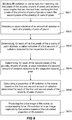
- a method of producing a color image of a scene captured by a camera exposed to radiation comprising both visible light and IR-radiation comprises: Detecting S602 a value indicative of an amount of radiation in each of a plurality of pairs of pixels, wherein each pair comprises a first pixel and a second pixel.
- the camera comprises an image sensor comprising a plurality of pairs of pixels as discussed above.
- Determining S604 for each of the first pixels of the plurality of pairs of pixels, a value indicative of a first amount of radiation detected by the respective first pixel.
- the method may further comprise blocking IR-radiation or visible light from reaching the first pixels of the plurality of pairs of pixels and allowing wavelengths that are blocked from reaching the first pixels of the plurality of pairs of pixels to reach the second pixels of the plurality of pairs of pixels.
- the aperture 110 may have some extra features in terms of control and design.
- a design feature may involve the incorporation of the filter 112.
- the filter 112 may be configured to filter IR-radiation differently in the first and second radiation paths.
- the first portion 300 of the filter 112 may be configured to block all IR-radiation and the second portion 302 of the filter 112 may be configured to block all IR-radiation except a predetermined sub-portion of wavelengths in the IR-spectrum. This may, e.g., be useful in implementations when an IR illuminator is used for illuminating the scene viewed by the camera 100, the IR illuminator being configured to illuminate the scene with wavelengths within the predetermined sub-portion of wavelengths in the IR-spectrum.
- the second portion of the filter is configured to allow IR-radiation in the predetermined sub-portion of wavelengths in the IR-spectrum to reach the image sensor. Then the IR-radiation in the predetermined sub-portion of wavelengths in the IR-spectrum may be compensated for.
- the IR illuminator may be arranged in or on the camera, or elsewhere in the scene.
- filter may be used to filter radiation reaching the first and second pixels of the pairs of pixels differently.
- different portions of the visible spectrum may be filtered differently.
- the green light may be filtered differently in order to study plants. Knowing spectral information about one or more disturbing light sources in an environment, the contribution of such light sources may be compensated for by using a filter having a first portion blocking the wavelengths of the one or more disturbing light sources and a second portion allowing the same wavelengths to pass, together with the image sensor comprising the plurality of pairs of pixels.
- the same principle may be used, e.g., for studying ultraviolet radiation content in incoming radiation, by selectively blocking or transmitting UV radiation.
- one or more of the detecting of a value indicative of an amount of radiation in each of a plurality of pairs of pixels, the determining, for each of the first pixels of the plurality of pairs of pixels, a value indicative of a first amount of radiation detected by the respective first pixel, the determining for each of the second pixels of the plurality of pairs of pixels a value indicative of a second amount of radiation detected by the respective second pixel, the calculating a proportion of IR-radiation in the scene based on the first and second amount of radiation determined for each of the first and second pixels of the plurality of pairs of pixels, and the producing the color image of the scene by compensating for an IR-contribution in an image captured by the camera based on the calculated proportion of IR-radiation may be made in a device separate from the camera 100.
- the camera 100 may be configured to communicate with a device separate from the camera.
- a device may, e.g., be a server.
- the server may, e.g., be configured to service a plurality of cameras with the production of color images.
- the server may be configured to control one or more cameras as the camera 100 discussed above to set the one or more cameras in a day mode or in a night mode.
- the filter 112 preferably is not used but instead an IR-cut filter blocking all IR-radiation from reaching the image sensor is used.
- the filter 112 may be retracted from the beam path of the respective camera 100 and the IR-cut filter may be inserted into the beam path of the respective camera 100.
- the night mode the filter 112 is inserted into the beam path of the respective camera 100 and the IR-cut filter is retracted from the beam path of the respective camera 100.
- the first portion 300 of the filter 112 may be configured to block all IR-radiation and the second portion 302 of the filter 112 may be configured to block all IR-radiation except a predetermined sub-portion of wavelengths in the IR-spectrum corresponding to wavelengths emitted by an IR illuminator arranged in the camera or elsewhere in the scene.
- the first portion of the filter may be transparent to visible light and the IR illuminator sub-portion of IR radiation, whereas the second portion of the filter blocks all IR radiation and only allows visible light through. In a mixed light scene, i.e.
- a scene with IR radiation and a low level of visible light such a configuration may be useful if the IR illuminator provides all or almost all the IR radiation in the scene, and there is little or no IR radiation outside the illuminator sub-spectrum.
- the IR-radiation added by the illuminator increases the total amount of radiation in the scene, and hence reduces the need for gain on the image sensor.
- the pixel pairs and the split filter makes it possible to determine the IR component and compensate for it, such that color images with good color fidelity may be produced also in low light, such as at dusk and dawn.
- the filter arrangement may be provided with an additional, movable filter, which blocks all IR radiation, or at least the spectral range of the IR illuminator, but is transparent to visible light.
- an additional, movable filter which blocks all IR radiation, or at least the spectral range of the IR illuminator, but is transparent to visible light.
- the movable IR cut filter may be removed, and the IR illuminator switched on, thereby allowing IR radiation from the illuminator to reach one pixel of each pixel pair.
- darkness such as at night, the movable IR cut filter should remain removed, and black and white images may be produced based on IR radiation from the illuminator and other sources, whereas the visible light contribution is insignificant.
- the first and second pixels are each part of a pair of pixels. It should, however, be noted that the first and second pixels may be part of larger groups of pixels, such as triplets or quadruplets of pixels. In a triplet of pixels, there may, for instance be one first pixel and two second pixels, or vice versa. In a quadruplet of pixels, there may be two first pixels and two second pixels, but there may as well be one first pixel and three second pixels, or vice versa.
Description
- The present invention relates to producing color images, and especially a camera design allowing for producing color images under low light conditions.
- Image sensors used in digital cameras have a spectral response with a non-negligible component in the infrared, IR. This results in opportunities as well as challenges.
- An opportunity lies in that during night time, or in low-light conditions the IR-component may provide useful information about the imaged scene. Typically, low light conditions occur during dusk or dawn. Other low light condition scenes are badly lit rooms. Low-light condition may also be defined as conditions where the amount of visible light and IR-radiation are comparable, hence, low-light condition may also be referred to as a mixed light condition.
- During night time, or in low-light conditions use may be made of incoming radiation from the IR portion of the spectrum. The IR radiation will not contain any color information, and instead of performing a color separation, the only parameter is the intensity of the incoming radiation, which may be presented as a black and white intensity image (or with any desirable color scale).
- A challenge is found during day-time imaging, where the addition of an IR-component may distort the color balance in images captured using a digital camera. In some situations, some or all pixels of the image sensor may even be completely saturated by the infrared component.
- A way of maintaining the beneficial effects while suppressing the less beneficial effects is to add a movable IR-cut filter in the beam path in front of the image sensor. In this way, the IR-cut filter may be used during daylight conditions, enabling acquisition of color images. Pixels of the image sensor will then operate in a first manner, where the incident light is divided into colors and detected as a charge on individual photodetectors thus enabling color separation. The IR-cut filter will be removed during night time, or in low-light conditions allowing IR-radiation to reach the image sensor. Pixels of the image sensor will then operate in a second manner, where the only parameter measured by the pixels is the intensity of the incoming radiation. Hence, intensity based images may be captured, and presented in black and white.
- There may, however, be instances where it would be desirable to be able to capture color separated images even in low-light conditions.
-
US 2011/228145 A1 is disclosing a camera comprising an IR-filter that is partially blocking the optical path of the light entering the camera. In order to determine the amount of IR-light the filter has to be removed from the optical path.JP 2003 264842 A - In view of the above, it is an object of the present invention to provide means for capturing color separated images even in low-light conditions.
- According to a first aspect a camera is provided. The camera comprises: an aperture; an image sensor comprising a plurality of pairs of pixels in which pair: a first pixel is configured such that it detects radiation which has entered the camera through the aperture and travelled from the aperture to the image sensor via a first radiation path, and a second pixel is configured such that it detects radiation which has entered the camera through the aperture and travelled from the aperture to the image sensor via a second radiation path, the second radiation path being different from the first radiation path; and a filter arranged in, or in the vicinity of, the aperture, wherein the filter comprises a first portion configured to block IR-radiation or visible light and a second portion configured to be transparent to wavelengths that are blocked by the first portion, wherein the filter is arranged such that radiation passing the first portion travels to the first pixels of the plurality of pairs of pixels, and such that radiation passing the second portion travels to the second pixels of the plurality of pairs of pixels.
- Hence, improved imaging is enabled. This due to that components of IR-radiation may be determined by comparing radiation detected by the first and second pixels in each pair of first and second pixels, and compensating for that IR portion. For example, a color image may be produced by determining the IR-portion of radiation detected by the image sensor. In this way, a true color representation may be obtained, even though the imaged scene contains IR-radiation which is captured by the image sensor.
- The term "radiation" is to be construed as radiation comprising spectral components both in the infrared spectral range and in the visible light spectral range.
- The first portion of the filter may be configured to block IR-radiation.
- The first portion of the filter may be configured to block visible light.
- The second portion of the filter may be configured to be transparent to both IR-radiation and visible light.
- The first portion of the filter may be configured to block IR-radiation and the second portion of the filter may be configured to block visible light.
- The filter may be fixedly positioned in, or in the vicinity of, the aperture. A simple camera with very few movable parts may thus be provided. The filter does not have to be (often cannot be) exactly in the aperture plane, but as long as it is close enough, it does not matter which side of the aperture it is.
- The filter has to be close to the aperture. It does not have to be (often cannot be) exactly in the aperture plane, but as long as it is close enough, it does not matter which side of the aperture it is.
- The filter may movable such that it may be positioned in and retracted from the first and second radiation paths. Thus, it will be possible to put the camera in different modes, such as a day mode wherein the filter with the first and second portions are used for calculating a proportion of IR-radiation in the scene based on an amount of radiation detected by each of the first and second pixels of the plurality of pairs of pixels and a night mode wherein the filter is removed, and the full spectral response of the image sensor is used for producing black and white images.
- The filter is useful when the scene comprises both visible light and IR-radiation. In these situations, it is possible to compensate for the IR-radiation and get good color fidelity. This is particularly useful in mixed light (low light, such as at dusk and dawn), where in implementation of today a switch to only registering the amount of radiation removing the IR cut filter is used. This is needed when the visible light level gets too low. In day light or good light, the IR-radiation is not needed, because there is plenty of visible light. However, the camera set up according to the present invention makes it possible to compensate for the IR-radiation. In traditional monitoring cameras, this is when the IR cut filter is inserted.
- At night, or in other really low light, there is basically no visible light, and at least a lot more IR radiation than visual light, so it will be very hard to produce color images. Thus, the filter might be removed at night. This so that as much radiation as possible is reaching the image sensor (by not blocking any IR-radiation). This switch to night mode may be postponed to lower light levels using the present invention.
- The portioning of the filter may be aligned with the first and second pixels such that: IR-radiation will not reach the first pixels in the pair of pixels, and IR-radiation will reach the second pixels in the pair of pixels.
- Each pixel of the image sensor may belong to a respective pair of pixels.
- The image sensor may be configured to, upon the camera being exposed to radiation comprising both visible light and IR-radiation, register a value indicative of an amount of radiation reaching each of the plurality of pairs of pixels. The camera may further comprise a processing unit configured to: determine, for each of the first pixels of the plurality of pairs of pixels, a value indicative of a first amount of radiation detected by the respective first pixel, determine, for each of the second pixels of the plurality of pairs of pixels, a value indicative of a second amount of radiation detected by the respective second pixel, calculate a proportion of IR-radiation in the scene based on the first and second amount of radiation determined for each of the first and second pixels of the plurality of pairs of pixels, and produce a color image of the scene by compensating for an IR-contribution in an image captured by the camera based on the calculated proportion of IR-radiation.
- According to a second aspect a method of producing a color image of a scene captured by a camera exposed to radiation comprising both visible light and IR-radiation is provided. The method comprises: detecting a value indicative of an amount of radiation in each of a plurality of pairs of pixels, wherein each pair comprises a first pixel and a second pixel, determining, for each of the first pixels of the plurality of pairs of pixels, a value indicative of a first amount of radiation detected by the respective first pixel, determining for each of the second pixels of the plurality of pairs of pixels a value indicative of a second amount of radiation detected by the respective second pixel, calculating a proportion of IR-radiation in the scene based on the first and second amount of radiation determined for each of the first and second pixels of the plurality of pairs of pixels, and producing the color image of the scene by compensating for an IR-contribution in an image captured by the camera based on the calculated proportion of IR-radiation.
- The method may further comprise blocking IR-radiation or visible light from reaching the first pixels of the plurality of pairs of pixels, and allowing wavelengths that are blocked from reaching the first pixels of the plurality of pairs of pixels to reach the second pixels of the plurality of pairs of pixels.
- The above mentioned features of the camera, when applicable, apply to this second aspect as well. In order to avoid undue repetition, reference is made to the above.
- According to a third aspect a non-transitory computer readable storage medium is provided. The non-transitory computer readable storage medium has computer readable program code stored thereon which when executed on a device having processing capability is configured to perform the method according to the second aspect.
- A further scope of applicability of the present invention will become apparent from the detailed description given below. However, it should be understood that the detailed description and specific examples, while indicating preferred embodiments of the invention, are given by way of illustration only, since various changes and modifications within the scope of the invention will become apparent to those skilled in the art from this detailed description.
- Hence, it is to be understood that this invention is not limited to the particular component parts of the device described or steps of the methods described as such device and method may vary. It is also to be understood that the terminology used herein is for purpose of describing particular embodiments only, and is not intended to be limiting. It must be noted that, as used in the specification and the appended claim, the articles "a," "an," "the," and "said" are intended to mean that there are one or more of the elements unless the context clearly dictates otherwise. Thus, for example, reference to "a unit" or "the unit" may include several devices, and the like. Furthermore, the words "comprising", "including", "containing" and similar wordings does not exclude other elements or steps.
- The above and other aspects of the present invention will now be described in more detail, with reference to appended drawings showing embodiments of the invention. The figures should not be considered limiting the invention to the specific embodiment; instead they are used for explaining and understanding the invention.
- As illustrated in the figures, the sizes of layers and regions may be exaggerated for illustrative purposes and, thus, are provided to illustrate the general structures of embodiments of the present invention. Like reference numerals refer to like elements throughout.
-
Fig. 1 illustrates a camera. -
Figs 2a, 2b and 2c illustrate different embodiments of an image sensor comprising pairs of pixels. -
Figs 3a, 3b and 3c illustrate different embodiments of a filter. -
Figs 4a, 4b and 4c illustrate different configurations of filters and how they block IR-radiation and/or visible light. -
Fig. 5 illustrates response curves for red, green and blue pixels of an image sensor. -
Fig. 6 is a flow diagram of a method of producing a color image. - The present invention will now be described more fully hereinafter with reference to the accompanying drawings, in which currently preferred embodiments of the invention are shown. This invention may, however, be embodied in many different forms and should not be construed as limited to the embodiments set forth herein; rather, these embodiments are provided for thoroughness and completeness, and to fully convey the scope of the invention to the skilled person.
-
Fig. 1 illustrates acamera 100 having animage sensor 102 and acamera lens housing 104. The camera may be a video camera. Thecamera 100 may be a monitoring camera. - The
camera lens housing 104 and theimage sensor 102 are arranged such that radiation entering thecamera 100 via thecamera lens housing 104 is interacting with theimage sensor 102. Hence, the camera is configured to capture images of a scene viewed by alens system 108 of thecamera lens housing 104. The radiation entering thecamera 100 typically comprises both visible light and IR-radiation. - For capturing the images of the scene the
image sensor 102 comprises a plurality of pixels distributed over a plane of theimage sensor 102. The pixels of the image sensor are typically sensitive to both visible light and IR-radiation, or more particularly near-infrared radiation (NIR). If the transmitted radiation were fully spectrally resolved it would be readily possible to monitor and evaluate the proportions of different colors of visible light and IR-radiation, but it should be noted that generally the image sensor 102 (and associated components, comprising e.g. an image processor 120) will at the most sort the incoming radiation into red, green and blue components, each of the color components including an IR component, which is indicated inFig. 5 , so as to be able to regenerate a color image. InFig. 5 response curves for red, green and blue pixels of an image sensor are exemplified. It is generally not possible to isolate the IR-component at all. For some implementations an IR-cut filter is used for blocking the IR-component of radiation before the radiation is arriving at the image sensor. The reason is that introduction of IR-radiation to the image sensor will distort the color correction performed by a camera controller, since IR-radiation will affect all pixels, referring toFig. 5 , and an IR-cut filter is necessary to be able to provide a true color representation. - The
camera lens housing 104 comprises alens system 108 and anaperture 110. - The
aperture 110 may also be referred to as a diaphragm. The role of theaperture 110 is to stop the passage of light, except for the light passing through theaperture 110. Theaperture 110 may be a fixed aperture having a fixed sized opening. By having a fixed aperture having a fixed sized opening a camera with less moveable parts is provided. Alternatively, theaperture 110 may be an iris aperture wherein the size of the aperture opening may be varied. By controlling the size of the opening of theaperture 110 it is possible to control the amount of radiation reaching theimage sensor 102, which of course is well known from regular iris apertures used in cameras. - The
aperture 110 is placed in a so called aperture stop plane of thelens system 108, or rather as close to the aperture stop plane as physically possible. In the rest of this disclosure the aperture stop plane will simply be referred to as the aperture stop. In a normal configuration the plane of the aperture stop represents a position where there is no spatial correlation with the plane of theimage sensor 102. For an ideal single-lens system the aperture stop would be positioned in the middle of the lens, orthogonally to the optical axis. The aperture stop limits how much light from each point of the object that reaches a conjugate image point (the image sensor in our case). The aperture stop thus defines a plane in the beam path, and sometimes the term "aperture plane" is used for the same feature. A feature of this plane is that it is a position in which alterations in a size of an aperture will affect the entire image plane equally, at least in an ideal situation. Further to what has already been discussed, the features of the aperture stop imply that the size of the aperture will only affect the amount of light reaching theimage sensor 102, not the actual image. More specifically, it will not generate any shadowing or similar effects or artefacts in the image plane, i.e. in the plane of theimage sensor 102. For this reason, it is standard practice to position the aperture 110 (the diaphragm) in the aperture stop. Within the context of the present description "the aperture" corresponds to an iris aperture or a fixed sized aperture arranged in or in the vicinity to the aperture stop. The filter shall preferably be close enough to the aperture that all light passing the filter affects the image sensor equally. - Returning to the
image sensor 102, at least some pixels of theimage sensor 102 belongs to a plurality of pairs of pixels. Hence, theimage sensor 102 comprises a plurality of pairs of pixels. In the literature the plurality of pairs of pixels is often named phase pixels, phase detection pixels, or dual pixels. Image sensors with a plurality of pairs of pixels, as used for the present invention, are today already used for performing phase detection autofocusing. Some such known sensors have a relatively small number of phase pixels spread over the sensor are, whereas in others all pixels are phase pixels. - All the pixels of the
image sensor 102 may be phase pixels. Hence, as illustrated inFig 2a , each pixel of theimage sensor 102 may belong to a respective pair of pixels. Each pair of pixels comprises afirst pixel 200 and asecond pixel 202. Alternatively, theimage sensor 102 may have a smaller number of phase pixels spread out over the sensor area. Hence, as illustrated inFigs 2b and 2c , a subset of the pixels of theimage sensor 102 may belong to a respective pair of pixels. - In each pair of pixels, the
first pixel 200 is configured such that it detects radiation which has entered thecamera 100 through theaperture 110 and travelled from theaperture 110 to theimage sensor 102 via a first radiation path, and thesecond pixel 202 is configured such that it detects radiation which has entered thecamera 100 through theaperture 110 and travelled from theaperture 110 to theimage sensor 102 via a second radiation path. The second radiation path is different from the first radiation path. The second radiation path may be separate from the first radiation path. Hence, the first and second radiation paths may be non-overlapping. - In each pair of pixels, a first half of the
first pixel 200 may be masked such that thefirst pixel 200 detects radiation which has entered thecamera 100 through theaperture 110 and travelled from theaperture 110 to theimage sensor 102 via the first radiation path and a second half of thesecond pixel 202 may be masked such that thesecond pixel 202 detects radiation which has entered thecamera 100 through theaperture 110 and travelled from theaperture 110 to theimage sensor 102 via the second radiation path. The second half may be complementary to the first half. - In each pair of pixels, a
first pixel 200 may be shaped such that thefirst pixel 200 detects radiation which has entered thecamera 100 through theaperture 110 and travelled from theaperture 110 to theimage sensor 102 via the first radiation path, and asecond pixel 202 may be shaped such that thesecond pixel 202 detects radiation which has entered thecamera 100 through theaperture 110 and travelled from theaperture 110 to theimage sensor 102 via the second radiation path. Thesecond pixel 202 may be complementary shaped with respect to the to thefirst pixel 200. - The
camera lens housing 104 further comprises afilter 112. Thefilter 112 is arranged in, or in the vicinity of, theaperture 110. Thefilter 112 is preferably close enough to the aperture plane such that only the amount of light is affected, not the spatial image. There is an added benefit in having thefilter 112 in, or in the vicinity of, theaperture 110, and thereby close to the plane of the aperture stop. This since in a normal configuration the plane of the aperture stop represents a position where there is no spatial correlation with the plane of theimage sensor 102. - In case the
filter 112 is arranged in the vicinity of theaperture 110, thefilter 112 may be arranged in between theaperture 110 and theimage sensor 102, or on the outside of the aperture. - As illustrated in
Figs 3a, 3b and 3c , thefilter 112 comprises afirst portion 300 configured to block IR-radiation or visible light and asecond portion 302 configured to be transparent to wavelengths that are blocked by the first portion. - The
filter 112 may be made out of a material transparent to visible light and to IR-radiation. Examples of such material are glass and plastics. The filter may comprise a solid sheet. The sheet may be partly covered by one or more coatings. The portion of thefilter 112 with the one or more coatings may be thefirst portion 300 of thefilter 112. Also thesecond portion 302 of thefilter 112 may be covered by one or more coatings. However, thesecond portion 302 of the filter may also not be covered by any wavelength blocking coatings. A specific composition of one or more coatings may block radiation with wavelengths in a specific range of wavelengths and may allow radiation with wavelengths in another specific range of wavelengths to pass. This will be further discussed in connection withFigs. 4a, 4a and 4c . - The portioning of the
filter 112 may be made, just as illustrated inFig. 3a , such that thefirst portion 300 represents a first half of thefilter 112 and thesecond portion 302 represents a second half of thefilter 112, the second half being complementary to the first half. However, the portioning may be made differently, this will now be discussed further in connection withFigs. 3b and 3c . -
Figs 3b and 3c illustrate two different exemplifying embodiments of afilter 112 having afirst portion 300 being larger than thesecond portion 302. According to these exemplifying embodiments thefirst portion 300 is configured to block IR-radiation. The filter designs exemplified inFigs 3b and 3c are just two examples out of many possible designs where thefirst portion 300 is larger than thesecond portion 302. By making the IR-blocking portion of thefilter 112 larger than the non-IR-blocking portion of thefilter 112 the risk of leakage of IR-radiation to the pixels out of the pairs of pixels that are not supposed to detect IR-radiation is reduced. Still, this may come at the expense that the estimation of IR-radiation in the scene may not be as accurate, since the pixels in the second path will get a mixture of filtered and unfiltered radiation. According to the filter design illustrated inFig. 3c , thefilter 112 may have a dual function. In addition to partly blocking IR-radiation, as being useful for low light conditions as is discussed within the context of this disclosure, thefilter 112 may also be used as an IR-cut filter during day light conditions. This since during day light conditions theaperture 110, in the form of an iris aperture, is typically reduced in size such that it is operated within anarea 306 located within thefirst portion 300 of thefilter 112. With such a design of the filter, the above-mentioned problem with mixing filtered and unfiltered radiation in the second path may be alleviated if the pixels in the pixel pairs are formed with different sizes, such that they receive different amounts of light. - The
filter 112 may be movable such that it may be positioned in and retracted from the first and second radiation paths. Alternatively, thefilter 112 may be fixedly positioned in, or in the vicinity of, theaperture 110. - The
filter 112 and theimage sensor 102 are arranged such that the portioning of thefilter 112 is aligned with or parallel to the orientation of the first andsecond pixels first pixels 200 will receive radiation having passed thefirst portion 300 of thefilter 112 and thesecond pixels 202 will receive radiation having passed thesecond portion 302 of thefilter 112. Thefilter 112 and theimage sensor 102 is thus arranged relative to each other such that radiation passing thefirst portion 300 of thefilter 112 travels to thefirst pixels 200 of the plurality of pairs of pixels, and such that radiation passing thesecond portion 302 of thefilter 112 travels to thesecond pixels 202 of the plurality of pairs of pixels. The aligning of thefilter 112 and theimage sensor 102 may be made such that the portioning of thefilter 112 is arranged parallel to an orientation of the first andsecond pixels image sensor 102. - In the embodiments shown, the pixel pairs as well as the filter are divided into a left portion and a right portion. It should be noted that also other divisions are possible, such as an upper portion and a lower portion, or any other orientation.
- The present set-up with the
filter 112 having afirst portion 300 configured to block IR-radiation or visible light and asecond portion 302 configured to be transparent to wavelengths that are blocked by the first portion, and theimage sensor 102 comprising a plurality of pairs of pixels as defined above enables estimation of an amount of IR-radiation comprised in the radiation entering thecamera 100. This using an image sensor which does not in itself discriminate between visible light and IR-radiation. The estimation of the amount of IR-radiation may, e.g., be used for producing color images even during low light conditions. This will be discussed in more detail further down in this description. - There are a number of possible configurations of the
filter 112 that may be used in connection with the present invention. - According to a first configuration, the
first portion 300 is configured to block IR-radiation and thesecond portion 302 is configured to be transparent to IR-radiation. For this first configuration, both thefirst portion 300 and thesecond portion 302 of thefilter 112 are configured to allow visible light to pass. Accordingly, thefirst portion 300 of thefilter 112 is configured to block IR-radiation and allow visible light to pass and thesecond portion 302 of thefilter 112 is configured to allow both visible light and IR-radiation to pass. This is illustrated inFig 4a . Radiation having intensity in both the visible spectral range, Ivis, and in the IR spectral range, IIR, is entering thefilter 112. Thefirst portion 300 of thefilter 112 will block IR radiation and allow visible light to pass, hence, the radiation passing thefirst portion 300 of thefilter 112 will only have intensity in the visible spectral range, Ivis. Thesecond portion 302 of thefilter 112 will allow both IR radiation and visible light to pass, hence, the radiation passing thesecond portion 302 of thefilter 112 will have intensity in both the IR spectral range, IIR, and the visible spectral range, Ivis. Thefirst pixels 200 of the plurality of pixels will then produce a signal, S1, proportional to Ivis and thesecond pixels 202 of the plurality of pixels will then produce a signal, S2, proportional to Ivis+IIR. From this the amount of IR radiation may be estimated as S2-S1. Further, the contribution from visible light in signals, Stot, from pixels of theimages sensor 102 detecting both IR-radiation and visible light may then be estimated to be, Stot-(S2-S1). - According to a second configuration, the
first portion 300 is configured to block visible light and thesecond portion 302 is configured to be transparent to visible light. For this second configuration, both thefirst portion 300 and thesecond portion 302 of thefilter 112 are configured to allow IR-radiation to pass. Accordingly, thefirst portion 300 of thefilter 112 is configured to block visible light and allow IR-radiation to pass and thesecond portion 302 of thefilter 112 is configured to allow both visible light and IR-radiation to pass. This is illustrated inFig 4b . Radiation having intensity in both the visible spectral range, Ivis, and in the IR spectral range, IIR, is entering thefilter 112. Thefirst portion 300 of thefilter 112 will block visible light and allow IR radiation to pass, hence, the radiation passing thefirst portion 300 of thefilter 112 will only have intensity in the IR spectral range, IIR. Thesecond portion 302 of thefilter 112 will allow both IR radiation and visible light to pass, hence, the radiation passing thesecond portion 302 of thefilter 112 will have intensity in both the IR spectral range, IIR, and the visible spectral range, Ivis. Thefirst pixels 200 of the plurality of pixels will then produce a signal, S1, proportional to IIR and thesecond pixels 202 of the plurality of pixels will then produce a signal, S2, proportional to Ivis+IIR. From this the amount of IR radiation may be estimated as S1. Further, the contribution from visible light in signals, Stot, from pixels of theimages sensor 102 detecting both IR-radiation and visible light may then be estimated to be, Stot-Si. - According to a third configuration, the
first portion 300 is configured to block IR-radiation and thesecond portion 302 is configured to be transparent to IR-radiation. Further, thefirst portion 300 is configured to be transparent to visible light and thesecond portion 302 is configured to block visible light. Accordingly, thefirst portion 300 of thefilter 112 is configured to block IR-radiation and allow visible light to pass and thesecond portion 302 of thefilter 112 is configured to allow IR-radiation to pass and to block visible light. This is illustrated inFig 4c . Radiation having intensity in both the visible spectral range, Ivis, and in the IR spectral range, IIR, is entering thefilter 112. Thefirst portion 300 of thefilter 112 will block IR radiation and allow visible light to pass, hence, the radiation passing thefirst portion 300 of thefilter 112 will only have intensity in the visible spectral range, Ivis. Thesecond portion 302 of thefilter 112 will allow IR radiation to pass but will block visible light, hence, the radiation passing thesecond portion 302 of thefilter 112 will have intensity in the IR spectral range, IIR. Thefirst pixels 200 of the plurality of pixels will then produce a signal, S1, proportional to Ivis and thesecond pixels 202 of the plurality of pixels will then produce a signal, S2, proportional to IIR. From this the amount of IR radiation may be estimated as S2. Further, the contribution from visible light in signals, Stot, from pixels of theimages sensor 102 detecting both IR-radiation and visible light may then be estimated to be, Stot-S2. - Hence, regardless of the configuration of the filter 112 a proportion of IR-radiation in the scene may be calculated.
- The
camera 100 may comprise aprocessor 124. Theprocessor 124 may be a single core processor or a multicore processor. Theprocessor 124 may be any suitable processor for performing digital data processing. Theprocessor 124 may be configured to process signals from thefirst pixels 200 of the plurality of pairs of pixels and signals from thesecond pixels 202 of the plurality of pairs of pixels. Alternatively, theimage processor 120 may be configured to process signals from thefirst pixels 200 of the plurality of pairs of pixels and signals from thesecond pixels 202 of the plurality of pairs of pixels. Yet alternatively, the signals from the first andsecond pixels processor 124 and partly by theimage processor 120. - The
camera 100 may further comprise amemory 122. Thememory 122 may be any kind of volatile or non-volatile memory. Further, thememory 122 may comprise a plurality of memory units. Thememory 122 may be used as a buffer memory for buffering data while performing processing by theprocessor 124 and/or theimage processor 120. The memory may, e.g., be configured to buffer information pertaining to pixel value signals for the pixels of theimage sensor 102. - The
image processor 120, thememory 122 and theprocessor 124 may communicate over adata bus 126. - A processing unit, either the
processor 124, theimage processor 120 or a combination thereof, of thecamera 100 may be configured to determine, for each of thefirst pixels 200 of the plurality of pairs of pixels, a value indicative of a first amount of radiation detected by the respectivefirst pixel 200. The processing unit of thecamera 100 may further be configured to determine, for each of thesecond pixels 202 of the plurality of pairs of pixels, a value indicative of a second amount of radiation detected by the respectivesecond pixel 202. Based on the values indicative of first and second amount of radiation determined for each of the first andsecond pixels image sensor 102 comprises a plurality of pairs of pixels a proportion of IR-radiation in different areas of the scene may be determined. This especially if the pairs of pixels are evenly distributed over an area of theimage sensor 102. - By determining the proportion of IR-radiation, it will be possible to evaluate the contribution of visual light. The evaluation may be performed on any level of resolution for the image, ranging from individual pixels or groups of pixels to larger portions of the image frame, or the entire image frame. Also, the evaluation may be based on single frames, but for better statistics a number of image frames may be combined to form a mean value before the evaluation is performed.
- Following the evaluation, it will be possible to isolate the contributions from visual and infrared wavelengths, and to compensate a resulting image accordingly. Hence, based on the calculated proportion of IR-radiation in the scene the processing unit may be configured to produce a color image of the scene by compensating for an IR-contribution in an image captured by the
camera 100. - In summary, in order to produce color images even under low light conditions it is realized that the following will give good results:
- Let as much radiation, i.e. both visible light and IR-radiation, as possible reach the
image sensor 102. This in order to reduce the gain needed on the image sensor and hence reduce the level of noise in the signal from the image sensor. - Determine the proportion of IR-radiation in the radiation reaching pixels of the
image sensor 102 detecting both visible light and IR-radiation. This by filtering the radiation reaching the first andsecond pixels - Produce a color image by compensating for an IR-contribution in an image captured by the camera.
- In connection with
Fig. 6 a method of producing a color image of a scene captured by a camera exposed to radiation comprising both visible light and IR-radiation will be discussed. The method comprises: Detecting S602 a value indicative of an amount of radiation in each of a plurality of pairs of pixels, wherein each pair comprises a first pixel and a second pixel. Hence, the camera comprises an image sensor comprising a plurality of pairs of pixels as discussed above. Determining S604, for each of the first pixels of the plurality of pairs of pixels, a value indicative of a first amount of radiation detected by the respective first pixel. Determining S606, for each of the second pixels of the plurality of pairs of pixels, a value indicative of a second amount of radiation detected by the respective second pixel. Calculating S608 a proportion of IR-radiation in the scene based on the first and second amount of radiation determined for each of the first and second pixels of the plurality of pairs of pixels. Producing S610 the color image of the scene by compensating for an IR-contribution in an image captured by the camera based on the calculated proportion of IR-radiation. - The method may further comprise blocking IR-radiation or visible light from reaching the first pixels of the plurality of pairs of pixels and allowing wavelengths that are blocked from reaching the first pixels of the plurality of pairs of pixels to reach the second pixels of the plurality of pairs of pixels.
- The person skilled in the art realizes that the present invention by no means is limited to the preferred embodiments described above. On the contrary, many modifications and variations are possible within the scope of the appended claims.
- For example, further to its normal operation, the
aperture 110 may have some extra features in terms of control and design. A design feature may involve the incorporation of thefilter 112. - Further, the
filter 112 may be configured to filter IR-radiation differently in the first and second radiation paths. For example, thefirst portion 300 of thefilter 112 may be configured to block all IR-radiation and thesecond portion 302 of thefilter 112 may be configured to block all IR-radiation except a predetermined sub-portion of wavelengths in the IR-spectrum. This may, e.g., be useful in implementations when an IR illuminator is used for illuminating the scene viewed by thecamera 100, the IR illuminator being configured to illuminate the scene with wavelengths within the predetermined sub-portion of wavelengths in the IR-spectrum. Then the second portion of the filter is configured to allow IR-radiation in the predetermined sub-portion of wavelengths in the IR-spectrum to reach the image sensor. Then the IR-radiation in the predetermined sub-portion of wavelengths in the IR-spectrum may be compensated for. The IR illuminator may be arranged in or on the camera, or elsewhere in the scene. - Also other types of filter may be used to filter radiation reaching the first and second pixels of the pairs of pixels differently. For example, different portions of the visible spectrum may be filtered differently. Just to mention one possible implementation, the green light may be filtered differently in order to study plants. Knowing spectral information about one or more disturbing light sources in an environment, the contribution of such light sources may be compensated for by using a filter having a first portion blocking the wavelengths of the one or more disturbing light sources and a second portion allowing the same wavelengths to pass, together with the image sensor comprising the plurality of pairs of pixels. With sensors sensitive to other parts of the radiation spectrum, the same principle may be used, e.g., for studying ultraviolet radiation content in incoming radiation, by selectively blocking or transmitting UV radiation.
- Moreover, one or more of the detecting of a value indicative of an amount of radiation in each of a plurality of pairs of pixels, the determining, for each of the first pixels of the plurality of pairs of pixels, a value indicative of a first amount of radiation detected by the respective first pixel, the determining for each of the second pixels of the plurality of pairs of pixels a value indicative of a second amount of radiation detected by the respective second pixel, the calculating a proportion of IR-radiation in the scene based on the first and second amount of radiation determined for each of the first and second pixels of the plurality of pairs of pixels, and the producing the color image of the scene by compensating for an IR-contribution in an image captured by the camera based on the calculated proportion of IR-radiation may be made in a device separate from the
camera 100. Hence, thecamera 100 may be configured to communicate with a device separate from the camera. Such a device may, e.g., be a server. The server may, e.g., be configured to service a plurality of cameras with the production of color images. The server may be configured to control one or more cameras as thecamera 100 discussed above to set the one or more cameras in a day mode or in a night mode. In the day mode thefilter 112 preferably is not used but instead an IR-cut filter blocking all IR-radiation from reaching the image sensor is used. Hence, thefilter 112 may be retracted from the beam path of therespective camera 100 and the IR-cut filter may be inserted into the beam path of therespective camera 100. In the night mode thefilter 112 is inserted into the beam path of therespective camera 100 and the IR-cut filter is retracted from the beam path of therespective camera 100. - As discussed above, the
first portion 300 of thefilter 112 may be configured to block all IR-radiation and thesecond portion 302 of thefilter 112 may be configured to block all IR-radiation except a predetermined sub-portion of wavelengths in the IR-spectrum corresponding to wavelengths emitted by an IR illuminator arranged in the camera or elsewhere in the scene. In a variant of this configuration, the first portion of the filter may be transparent to visible light and the IR illuminator sub-portion of IR radiation, whereas the second portion of the filter blocks all IR radiation and only allows visible light through. In a mixed light scene, i.e. a scene with IR radiation and a low level of visible light, such a configuration may be useful if the IR illuminator provides all or almost all the IR radiation in the scene, and there is little or no IR radiation outside the illuminator sub-spectrum. The IR-radiation added by the illuminator increases the total amount of radiation in the scene, and hence reduces the need for gain on the image sensor. The pixel pairs and the split filter makes it possible to determine the IR component and compensate for it, such that color images with good color fidelity may be produced also in low light, such as at dusk and dawn. Still, in daylight the sun may contribute significant amounts of IR radiation outside the spectral range of the IR illuminator, and therefore it would not be possible to determine the total amount of IR radiation in the incoming radiation. Therefore, the filter arrangement may be provided with an additional, movable filter, which blocks all IR radiation, or at least the spectral range of the IR illuminator, but is transparent to visible light. A filter arrangement using a combination of a fixed filter and a movable filter is described in applicant's European patent application No.16207126.0 - In the embodiments shown in
Figs. 2a-c , the first and second pixels are each part of a pair of pixels. It should, however, be noted that the first and second pixels may be part of larger groups of pixels, such as triplets or quadruplets of pixels. In a triplet of pixels, there may, for instance be one first pixel and two second pixels, or vice versa. In a quadruplet of pixels, there may be two first pixels and two second pixels, but there may as well be one first pixel and three second pixels, or vice versa. - Additionally, variations to the disclosed embodiments can be understood and effected by the skilled person without departing from the scope of the appended claims.
Claims (12)
- A camera comprising:an aperture (110);an image sensor (102) comprising a plurality of pairs of pixels, each pair of pixels comprising:a first pixel (200) is configured such that it detects radiation which has entered the camera through the aperture (110) and travelled from the aperture (110) to the image sensor (102) via a first radiation path, anda second pixel (202) is configured such that it detects radiation which has entered the camera through the aperture (110) and travelled from the aperture (110) to the image sensor (102) via a second radiation path, the second radiation path being different from the first radiation path; anda filter (112) arranged in, or in the vicinity of, the aperture (110), wherein the filter (112) comprises a first portion (300) configured to block IR-radiation or visible light and a second portion (302) configured to be transparent to wavelengths that are blocked by the first portion (300), wherein the filter (112) is arranged such that radiation passing the first portion (300) travels to the first pixels (200) of the plurality of pairs of pixels, and such that radiation passing the second portion (302) travels to the second pixels (202) of the plurality of pairs of pixels.
- The camera according to claim 1, wherein the first portion (300) of the filter (112) is configured to block IR-radiation and wherein the second portion (302) of the filter (112) is configured to be transparent to both IR-radiation and visible light.
- The camera according to claim 1, wherein the first portion (300) of the filter (112) is configured to block visible light and wherein the second portion (302) of the filter (112) is configured to be transparent to both IR-radiation and visible light.
- The camera according to claim 1, wherein the first portion (300) of the filter (112) is configured to block IR-radiation and wherein the second portion (302) of the filter (112) is configured to block visible light.
- The camera according to any one of claims 1-4, wherein the filter (112) is fixedly positioned in, or in the vicinity of, the aperture (110).
- The camera according to any one of claims 1-4, wherein the filter (112) is movable such that it may be positioned in and retracted from the first and second radiation paths.
- The camera according to any one of claims 2, 4-6, wherein the portioning of the filter is aligned with the first and second pixels such that:IR-radiation will not reach the first pixels in the pair of pixels, andIR-radiation will reach the second pixels in the pair of pixels.
- The camera according to any one of claims 1-7, wherein each pixel of the image sensor (102) belongs to a respective pair of pixels.
- The camera according to any one of claims 1-8, wherein the image sensor (102) is configured to, upon the camera being exposed to radiation comprising both visible light and IR-radiation, register a value indicative of an amount of radiation reaching each of the plurality of pairs of pixels, wherein the camera further comprises a processing unit (120; 124) configured to:determine, for each of the first pixels (200) of the plurality of pairs of pixels, a value indicative of a first amount of radiation detected by the respective first pixel (200),determine, for each of the second pixels (200) of the plurality of pairs of pixels, a value indicative of a second amount of radiation detected by the respective second pixel (202),calculate a proportion of IR-radiation in the scene based on the first and second amount of radiation determined for each of the first and second pixels (200; 202) of the plurality of pairs of pixels, andproduce a color image of the scene by compensating for an IR-contribution in an image captured by the camera based on the calculated proportion of IR-radiation.
- A method of producing a color image of a scene captured by a camera exposed to radiation comprising both visible light and IR-radiation, the method comprising:detecting a value indicative of an amount of radiation in each of a plurality of pairs of pixels, wherein each pair comprises a first pixel and a second pixel, the first pixel is configured such that it detects radiation which has entered the camera through an aperture and travelled from the aperture to an image sensor via a first radiation path, and the second pixel is configured such that it detects radiation which has entered the camera through the aperture and travelled from the aperture to the image sensor via a second radiation path, the second radiation path being different from the first radiation path,determining, for each of the first pixels of the plurality of pairs of pixels, a value indicative of a first amount of radiation detected by the respective first pixel,determining for each of the second pixels of the plurality of pairs of pixels a value indicative of a second amount of radiation detected by the respective second pixel,calculating a proportion of IR-radiation in the scene based on the first and second amount of radiation determined for each of the first and second pixels of the plurality of pairs of pixels, andproducing the color image of the scene by compensating for an IR-contribution in an image captured by the camera based on the calculated proportion of IR-radiation.
- The method according to claim 10, further comprising:blocking IR-radiation or visible light from reaching the first pixels of the plurality of pairs of pixels, andallowing wavelengths that are blocked from reaching the first pixels of the plurality of pairs of pixels to reach the second pixels of the plurality of pairs of pixels.
- A non-transitory computer readable storage medium having computer readable program code stored thereon which when executed on a device having processing capability is configured to perform the method of claim 10 or 11.
Priority Applications (5)
| Application Number | Priority Date | Filing Date | Title |
|---|---|---|---|
| US15/857,127 US10567713B2 (en) | 2016-12-28 | 2017-12-28 | Camera and method of producing color images |
| KR1020180050062A KR102100031B1 (en) | 2017-06-29 | 2018-04-30 | Camera and method of producing color images |
| CN201810597300.0A CN109218691A (en) | 2017-06-29 | 2018-06-11 | Video camera and the method for generating color image |
| JP2018115150A JP6606231B2 (en) | 2017-06-29 | 2018-06-18 | Camera and method for generating color images |
| TW107121501A TWI684365B (en) | 2017-06-29 | 2018-06-22 | Camera and method of producing color images |
Applications Claiming Priority (3)
| Application Number | Priority Date | Filing Date | Title |
|---|---|---|---|
| EP16207122.9A EP3343287B1 (en) | 2016-12-28 | 2016-12-28 | A method for sequential control of ir-filter, and an assembly performing such method |
| EP16207126.0A EP3343894B1 (en) | 2016-12-28 | 2016-12-28 | Ir-filter arrangement |
| EP17178716.1A EP3422700B1 (en) | 2017-06-29 | 2017-06-29 | A method for enhancing color images, and an assembly performing such method |
Publications (2)
| Publication Number | Publication Date |
|---|---|
| EP3343897A1 EP3343897A1 (en) | 2018-07-04 |
| EP3343897B1 true EP3343897B1 (en) | 2019-08-21 |
Family
ID=60673419
Family Applications (1)
| Application Number | Title | Priority Date | Filing Date |
|---|---|---|---|
| EP17209246.2A Active EP3343897B1 (en) | 2016-12-28 | 2017-12-21 | Camera and method of producing color images |
Country Status (2)
| Country | Link |
|---|---|
| US (1) | US10567713B2 (en) |
| EP (1) | EP3343897B1 (en) |
Family Cites Families (49)
| Publication number | Priority date | Publication date | Assignee | Title |
|---|---|---|---|---|
| JPH10171026A (en) | 1996-12-10 | 1998-06-26 | Fuji Photo Film Co Ltd | Image recorder |
| JP2001036807A (en) | 1999-07-19 | 2001-02-09 | Hitachi Ltd | Image pickup device |
| US6642955B1 (en) | 2000-01-10 | 2003-11-04 | Extreme Cctv Inc. | Surveillance camera system with infrared and visible light bandpass control circuit |
| JP4011829B2 (en) | 2000-06-14 | 2007-11-21 | キヤノン株式会社 | Imaging apparatus and control method thereof |
| JP2002049073A (en) | 2000-08-07 | 2002-02-15 | Asahi Precision Co Ltd | Diaphragm device for cctv camera lens |
| JP3803274B2 (en) | 2000-10-13 | 2006-08-02 | ペンタックス株式会社 | CCTV camera lens diaphragm device and diaphragm device unit |
| US7079186B2 (en) | 2000-10-13 | 2006-07-18 | Pentax Corporation | Diaphragm device of a television camera lens for a CCTV surveillance camera |
| JP3086673U (en) | 2001-12-13 | 2002-06-28 | 頼源松 | Two-layer water storage type flower pot assembly structure |
| JP2003264842A (en) * | 2002-03-08 | 2003-09-19 | Hitachi Kokusai Electric Inc | Filter, dimmer panel, and solid-state imaging device |
| JP3861241B2 (en) | 2002-03-15 | 2006-12-20 | 三菱電機株式会社 | Filter moving camera device |
| JP3727934B2 (en) | 2003-05-14 | 2005-12-21 | 株式会社タムロン | Aperture device and optical filter |
| JP2004361590A (en) | 2003-06-03 | 2004-12-24 | Sony Corp | Optical device and imaging apparatus |
| JP4438056B2 (en) | 2003-06-26 | 2010-03-24 | キヤノン株式会社 | Manufacturing method of light quantity adjusting member |
| JP2006078666A (en) | 2004-09-08 | 2006-03-23 | Fujinon Corp | Lens device |
| JP2006157413A (en) | 2004-11-29 | 2006-06-15 | Enplas Corp | Imaging apparatus |
| CN101064778A (en) | 2006-04-29 | 2007-10-31 | 上海乐金广电电子有限公司 | Photograph mode control method for monitor camera |
| KR101276757B1 (en) | 2006-05-26 | 2013-06-20 | 삼성전자주식회사 | Apparatus for photographing image and operating method for the same |
| JP5020651B2 (en) | 2007-02-02 | 2012-09-05 | キヤノン株式会社 | Imaging apparatus and imaging system |
| JP5098908B2 (en) | 2008-09-08 | 2012-12-12 | コニカミノルタアドバンストレイヤー株式会社 | Image input device |
| US7915652B2 (en) * | 2008-10-24 | 2011-03-29 | Sharp Laboratories Of America, Inc. | Integrated infrared and color CMOS imager sensor |
| JP5230388B2 (en) * | 2008-12-10 | 2013-07-10 | キヤノン株式会社 | Focus detection apparatus and control method thereof |
| WO2011033984A1 (en) | 2009-09-15 | 2011-03-24 | 株式会社大真空 | Optical filter |
| WO2011101036A1 (en) | 2010-02-19 | 2011-08-25 | Iplink Limited | Processing multi-aperture image data |
| US9091903B2 (en) | 2010-07-29 | 2015-07-28 | Logitech Europe S.A. | Optimized movable IR filter in cameras |
| US8357899B2 (en) | 2010-07-30 | 2013-01-22 | Aptina Imaging Corporation | Color correction circuitry and methods for dual-band imaging systems |
| KR20130115219A (en) | 2010-08-04 | 2013-10-21 | 니혼 세이미츠 속키 카부시키가이샤 | Aperture device, camera, and electronic device |
| US8408821B2 (en) | 2010-10-12 | 2013-04-02 | Omnivision Technologies, Inc. | Visible and infrared dual mode imaging system |
| JP2013152369A (en) | 2012-01-25 | 2013-08-08 | Nippon Seimitsu Sokki Kk | Diaphragm device and camera |
| US20130222603A1 (en) | 2012-02-28 | 2013-08-29 | Aptina Imaging Corporation | Imaging systems for infrared and visible imaging |
| JP5783279B2 (en) | 2013-02-08 | 2015-09-24 | 株式会社デンソー | Image processing device |
| JP6230265B2 (en) | 2013-05-17 | 2017-11-15 | キヤノン株式会社 | Imaging device |
| JP2015026675A (en) | 2013-07-25 | 2015-02-05 | ソニー株式会社 | Solid state image sensor, manufacturing method thereof and electronic apparatus |
| US20150062422A1 (en) | 2013-08-27 | 2015-03-05 | Semiconductor Components Industries, Llc | Lens alignment in camera modules using phase detection pixels |
| US10051211B2 (en) | 2013-12-05 | 2018-08-14 | Omnivision Technologies, Inc. | Image sensors for capturing both visible light images and infrared light images, and associated systems and methods |
| KR102197476B1 (en) | 2014-06-09 | 2020-12-31 | 에스케이하이닉스 주식회사 | Image sensor |
| US9699393B2 (en) | 2014-06-26 | 2017-07-04 | Semiconductor Components Industries, Llc | Imaging systems for infrared and visible imaging with patterned infrared cutoff filters |
| JP6190974B2 (en) | 2014-09-30 | 2017-08-30 | 富士フイルム株式会社 | Infrared imaging device, aperture control method, and aperture control program |
| US9813624B2 (en) | 2014-10-29 | 2017-11-07 | Canon Kabushiki Kaisha | Image pickup apparatus including infrared light reduction section, method of controlling the same, and storage medium |
| US20170230638A1 (en) | 2015-02-26 | 2017-08-10 | Dual Aperture International Co. Ltd. | Depth Measurement Techniques for a Multi-Aperture Imaging System |
| JP6530215B2 (en) | 2015-03-26 | 2019-06-12 | マクセル株式会社 | Lens unit and camera module |
| CN107534727B (en) * | 2015-04-23 | 2020-06-26 | 富士胶片株式会社 | Image processing device, imaging device, image processing method, and computer-readable non-transitory tangible recording medium having image processing program recorded thereon |
| US9420164B1 (en) | 2015-09-24 | 2016-08-16 | Qualcomm Incorporated | Phase detection autofocus noise reduction |
| US9671537B2 (en) * | 2015-10-22 | 2017-06-06 | Omnivision Technologies, Inc. | Multi-layer color filter for low color error and high SNR |
| CN105430363B (en) | 2015-12-18 | 2018-07-17 | 广东欧珀移动通信有限公司 | imaging method, imaging device and electronic device |
| US9906706B2 (en) | 2015-12-23 | 2018-02-27 | Visera Technologies Company Limited | Image sensor and imaging device |
| US10132971B2 (en) | 2016-03-04 | 2018-11-20 | Magna Electronics Inc. | Vehicle camera with multiple spectral filters |
| US9848118B2 (en) * | 2016-03-11 | 2017-12-19 | Intel Corporation | Phase detection autofocus using opposing filter masks |
| US10638060B2 (en) * | 2016-06-28 | 2020-04-28 | Intel Corporation | Color correction of RGBIR sensor stream based on resolution recovery of RGB and IR channels |
| US10574872B2 (en) * | 2016-12-01 | 2020-02-25 | Semiconductor Components Industries, Llc | Methods and apparatus for single-chip multispectral object detection |
-
2017
- 2017-12-21 EP EP17209246.2A patent/EP3343897B1/en active Active
- 2017-12-28 US US15/857,127 patent/US10567713B2/en active Active
Non-Patent Citations (1)
| Title |
|---|
| None * |
Also Published As
| Publication number | Publication date |
|---|---|
| US10567713B2 (en) | 2020-02-18 |
| US20180184054A1 (en) | 2018-06-28 |
| EP3343897A1 (en) | 2018-07-04 |
Similar Documents
| Publication | Publication Date | Title |
|---|---|---|
| KR102100031B1 (en) | Camera and method of producing color images | |
| CA2812860C (en) | Digital multi-spectral camera system having at least two independent digital cameras | |
| US7460160B2 (en) | Multispectral digital camera employing both visible light and non-visible light sensing on a single image sensor | |
| US8018509B2 (en) | Image input processing apparatus and method | |
| EP1975695B1 (en) | Focus detection device, focusing state detection method and imaging apparatus | |
| CN106101549B (en) | Automatic switching method, apparatus and system round the clock | |
| US20070177004A1 (en) | Image creating method and imaging device | |
| US9041930B1 (en) | Digital pathology system | |
| US11747533B2 (en) | Spectral sensor system using optical filter subarrays | |
| CN110493535B (en) | Image acquisition device and image acquisition method | |
| CN107995396B (en) | Two camera modules and terminal | |
| US11696043B2 (en) | White balance compensation using a spectral sensor system | |
| US20170134669A1 (en) | Image sensor and monitoring system | |
| WO2015149711A1 (en) | Infrared control device and method, and camera | |
| EP3343897B1 (en) | Camera and method of producing color images | |
| CN109862332B (en) | Method, apparatus and system for detecting and reducing color fringing effects | |
| CN113938600B (en) | Method for enhancing performance of video camera | |
| US9906705B2 (en) | Image pickup apparatus | |
| JP2011029858A (en) | Imaging apparatus | |
| JP2016200742A (en) | Imaging apparatus | |
| JP2019007826A (en) | Distance measuring camera and distance measurement method |
Legal Events
| Date | Code | Title | Description |
|---|---|---|---|
| PUAI | Public reference made under article 153(3) epc to a published international application that has entered the european phase |
Free format text: ORIGINAL CODE: 0009012 |
|
| STAA | Information on the status of an ep patent application or granted ep patent |
Free format text: STATUS: THE APPLICATION HAS BEEN PUBLISHED |
|
| STAA | Information on the status of an ep patent application or granted ep patent |
Free format text: STATUS: REQUEST FOR EXAMINATION WAS MADE |
|
| AK | Designated contracting states |
Kind code of ref document: A1 Designated state(s): AL AT BE BG CH CY CZ DE DK EE ES FI FR GB GR HR HU IE IS IT LI LT LU LV MC MK MT NL NO PL PT RO RS SE SI SK SM TR |
|
| AX | Request for extension of the european patent |
Extension state: BA ME |
|
| 17P | Request for examination filed |
Effective date: 20180530 |
|
| RBV | Designated contracting states (corrected) |
Designated state(s): AL AT BE BG CH CY CZ DE DK EE ES FI FR GB GR HR HU IE IS IT LI LT LU LV MC MK MT NL NO PL PT RO RS SE SI SK SM TR |
|
| GRAP | Despatch of communication of intention to grant a patent |
Free format text: ORIGINAL CODE: EPIDOSNIGR1 |
|
| STAA | Information on the status of an ep patent application or granted ep patent |
Free format text: STATUS: GRANT OF PATENT IS INTENDED |
|
| INTG | Intention to grant announced |
Effective date: 20190314 |
|
| GRAS | Grant fee paid |
Free format text: ORIGINAL CODE: EPIDOSNIGR3 |
|
| GRAA | (expected) grant |
Free format text: ORIGINAL CODE: 0009210 |
|
| STAA | Information on the status of an ep patent application or granted ep patent |
Free format text: STATUS: THE PATENT HAS BEEN GRANTED |
|
| AK | Designated contracting states |
Kind code of ref document: B1 Designated state(s): AL AT BE BG CH CY CZ DE DK EE ES FI FR GB GR HR HU IE IS IT LI LT LU LV MC MK MT NL NO PL PT RO RS SE SI SK SM TR |
|
| REG | Reference to a national code |
Ref country code: GB Ref legal event code: FG4D |
|
| REG | Reference to a national code |
Ref country code: CH Ref legal event code: EP |
|
| REG | Reference to a national code |
Ref country code: DE Ref legal event code: R096 Ref document number: 602017006363 Country of ref document: DE |
|
| REG | Reference to a national code |
Ref country code: AT Ref legal event code: REF Ref document number: 1171060 Country of ref document: AT Kind code of ref document: T Effective date: 20190915 |
|
| REG | Reference to a national code |
Ref country code: SE Ref legal event code: TRGR |
|
| REG | Reference to a national code |
Ref country code: IE Ref legal event code: FG4D |
|
| REG | Reference to a national code |
Ref country code: LT Ref legal event code: MG4D |
|
| REG | Reference to a national code |
Ref country code: NL Ref legal event code: MP Effective date: 20190821 |
|
| PG25 | Lapsed in a contracting state [announced via postgrant information from national office to epo] |
Ref country code: FI Free format text: LAPSE BECAUSE OF FAILURE TO SUBMIT A TRANSLATION OF THE DESCRIPTION OR TO PAY THE FEE WITHIN THE PRESCRIBED TIME-LIMIT Effective date: 20190821 Ref country code: LT Free format text: LAPSE BECAUSE OF FAILURE TO SUBMIT A TRANSLATION OF THE DESCRIPTION OR TO PAY THE FEE WITHIN THE PRESCRIBED TIME-LIMIT Effective date: 20190821 Ref country code: NL Free format text: LAPSE BECAUSE OF FAILURE TO SUBMIT A TRANSLATION OF THE DESCRIPTION OR TO PAY THE FEE WITHIN THE PRESCRIBED TIME-LIMIT Effective date: 20190821 Ref country code: BG Free format text: LAPSE BECAUSE OF FAILURE TO SUBMIT A TRANSLATION OF THE DESCRIPTION OR TO PAY THE FEE WITHIN THE PRESCRIBED TIME-LIMIT Effective date: 20191121 Ref country code: NO Free format text: LAPSE BECAUSE OF FAILURE TO SUBMIT A TRANSLATION OF THE DESCRIPTION OR TO PAY THE FEE WITHIN THE PRESCRIBED TIME-LIMIT Effective date: 20191121 Ref country code: PT Free format text: LAPSE BECAUSE OF FAILURE TO SUBMIT A TRANSLATION OF THE DESCRIPTION OR TO PAY THE FEE WITHIN THE PRESCRIBED TIME-LIMIT Effective date: 20191223 Ref country code: HR Free format text: LAPSE BECAUSE OF FAILURE TO SUBMIT A TRANSLATION OF THE DESCRIPTION OR TO PAY THE FEE WITHIN THE PRESCRIBED TIME-LIMIT Effective date: 20190821 |
|
| PG25 | Lapsed in a contracting state [announced via postgrant information from national office to epo] |
Ref country code: LV Free format text: LAPSE BECAUSE OF FAILURE TO SUBMIT A TRANSLATION OF THE DESCRIPTION OR TO PAY THE FEE WITHIN THE PRESCRIBED TIME-LIMIT Effective date: 20190821 Ref country code: RS Free format text: LAPSE BECAUSE OF FAILURE TO SUBMIT A TRANSLATION OF THE DESCRIPTION OR TO PAY THE FEE WITHIN THE PRESCRIBED TIME-LIMIT Effective date: 20190821 Ref country code: IS Free format text: LAPSE BECAUSE OF FAILURE TO SUBMIT A TRANSLATION OF THE DESCRIPTION OR TO PAY THE FEE WITHIN THE PRESCRIBED TIME-LIMIT Effective date: 20191221 Ref country code: GR Free format text: LAPSE BECAUSE OF FAILURE TO SUBMIT A TRANSLATION OF THE DESCRIPTION OR TO PAY THE FEE WITHIN THE PRESCRIBED TIME-LIMIT Effective date: 20191122 Ref country code: AL Free format text: LAPSE BECAUSE OF FAILURE TO SUBMIT A TRANSLATION OF THE DESCRIPTION OR TO PAY THE FEE WITHIN THE PRESCRIBED TIME-LIMIT Effective date: 20190821 Ref country code: ES Free format text: LAPSE BECAUSE OF FAILURE TO SUBMIT A TRANSLATION OF THE DESCRIPTION OR TO PAY THE FEE WITHIN THE PRESCRIBED TIME-LIMIT Effective date: 20190821 |
|
| REG | Reference to a national code |
Ref country code: AT Ref legal event code: MK05 Ref document number: 1171060 Country of ref document: AT Kind code of ref document: T Effective date: 20190821 |
|
| PG25 | Lapsed in a contracting state [announced via postgrant information from national office to epo] |
Ref country code: TR Free format text: LAPSE BECAUSE OF FAILURE TO SUBMIT A TRANSLATION OF THE DESCRIPTION OR TO PAY THE FEE WITHIN THE PRESCRIBED TIME-LIMIT Effective date: 20190821 |
|
| PG25 | Lapsed in a contracting state [announced via postgrant information from national office to epo] |
Ref country code: DK Free format text: LAPSE BECAUSE OF FAILURE TO SUBMIT A TRANSLATION OF THE DESCRIPTION OR TO PAY THE FEE WITHIN THE PRESCRIBED TIME-LIMIT Effective date: 20190821 Ref country code: EE Free format text: LAPSE BECAUSE OF FAILURE TO SUBMIT A TRANSLATION OF THE DESCRIPTION OR TO PAY THE FEE WITHIN THE PRESCRIBED TIME-LIMIT Effective date: 20190821 Ref country code: AT Free format text: LAPSE BECAUSE OF FAILURE TO SUBMIT A TRANSLATION OF THE DESCRIPTION OR TO PAY THE FEE WITHIN THE PRESCRIBED TIME-LIMIT Effective date: 20190821 Ref country code: PL Free format text: LAPSE BECAUSE OF FAILURE TO SUBMIT A TRANSLATION OF THE DESCRIPTION OR TO PAY THE FEE WITHIN THE PRESCRIBED TIME-LIMIT Effective date: 20190821 Ref country code: IT Free format text: LAPSE BECAUSE OF FAILURE TO SUBMIT A TRANSLATION OF THE DESCRIPTION OR TO PAY THE FEE WITHIN THE PRESCRIBED TIME-LIMIT Effective date: 20190821 Ref country code: RO Free format text: LAPSE BECAUSE OF FAILURE TO SUBMIT A TRANSLATION OF THE DESCRIPTION OR TO PAY THE FEE WITHIN THE PRESCRIBED TIME-LIMIT Effective date: 20190821 |
|
| PG25 | Lapsed in a contracting state [announced via postgrant information from national office to epo] |
Ref country code: SM Free format text: LAPSE BECAUSE OF FAILURE TO SUBMIT A TRANSLATION OF THE DESCRIPTION OR TO PAY THE FEE WITHIN THE PRESCRIBED TIME-LIMIT Effective date: 20190821 Ref country code: SK Free format text: LAPSE BECAUSE OF FAILURE TO SUBMIT A TRANSLATION OF THE DESCRIPTION OR TO PAY THE FEE WITHIN THE PRESCRIBED TIME-LIMIT Effective date: 20190821 Ref country code: CZ Free format text: LAPSE BECAUSE OF FAILURE TO SUBMIT A TRANSLATION OF THE DESCRIPTION OR TO PAY THE FEE WITHIN THE PRESCRIBED TIME-LIMIT Effective date: 20190821 Ref country code: IS Free format text: LAPSE BECAUSE OF FAILURE TO SUBMIT A TRANSLATION OF THE DESCRIPTION OR TO PAY THE FEE WITHIN THE PRESCRIBED TIME-LIMIT Effective date: 20200224 |
|
| REG | Reference to a national code |
Ref country code: DE Ref legal event code: R097 Ref document number: 602017006363 Country of ref document: DE |
|
| PLBE | No opposition filed within time limit |
Free format text: ORIGINAL CODE: 0009261 |
|
| STAA | Information on the status of an ep patent application or granted ep patent |
Free format text: STATUS: NO OPPOSITION FILED WITHIN TIME LIMIT |
|
| PG2D | Information on lapse in contracting state deleted |
Ref country code: IS |
|
| 26N | No opposition filed |
Effective date: 20200603 |
|
| REG | Reference to a national code |
Ref country code: BE Ref legal event code: MM Effective date: 20191231 |
|
| PG25 | Lapsed in a contracting state [announced via postgrant information from national office to epo] |
Ref country code: SI Free format text: LAPSE BECAUSE OF FAILURE TO SUBMIT A TRANSLATION OF THE DESCRIPTION OR TO PAY THE FEE WITHIN THE PRESCRIBED TIME-LIMIT Effective date: 20190821 Ref country code: MC Free format text: LAPSE BECAUSE OF FAILURE TO SUBMIT A TRANSLATION OF THE DESCRIPTION OR TO PAY THE FEE WITHIN THE PRESCRIBED TIME-LIMIT Effective date: 20190821 |
|
| PG25 | Lapsed in a contracting state [announced via postgrant information from national office to epo] |
Ref country code: IE Free format text: LAPSE BECAUSE OF NON-PAYMENT OF DUE FEES Effective date: 20191221 Ref country code: LU Free format text: LAPSE BECAUSE OF NON-PAYMENT OF DUE FEES Effective date: 20191221 |
|
| PG25 | Lapsed in a contracting state [announced via postgrant information from national office to epo] |
Ref country code: BE Free format text: LAPSE BECAUSE OF NON-PAYMENT OF DUE FEES Effective date: 20191231 |
|
| PG25 | Lapsed in a contracting state [announced via postgrant information from national office to epo] |
Ref country code: CY Free format text: LAPSE BECAUSE OF FAILURE TO SUBMIT A TRANSLATION OF THE DESCRIPTION OR TO PAY THE FEE WITHIN THE PRESCRIBED TIME-LIMIT Effective date: 20190821 |
|
| PG25 | Lapsed in a contracting state [announced via postgrant information from national office to epo] |
Ref country code: MT Free format text: LAPSE BECAUSE OF FAILURE TO SUBMIT A TRANSLATION OF THE DESCRIPTION OR TO PAY THE FEE WITHIN THE PRESCRIBED TIME-LIMIT Effective date: 20190821 Ref country code: HU Free format text: LAPSE BECAUSE OF FAILURE TO SUBMIT A TRANSLATION OF THE DESCRIPTION OR TO PAY THE FEE WITHIN THE PRESCRIBED TIME-LIMIT; INVALID AB INITIO Effective date: 20171221 |
|
| REG | Reference to a national code |
Ref country code: CH Ref legal event code: PL |
|
| PG25 | Lapsed in a contracting state [announced via postgrant information from national office to epo] |
Ref country code: CH Free format text: LAPSE BECAUSE OF NON-PAYMENT OF DUE FEES Effective date: 20201231 Ref country code: LI Free format text: LAPSE BECAUSE OF NON-PAYMENT OF DUE FEES Effective date: 20201231 |
|
| PG25 | Lapsed in a contracting state [announced via postgrant information from national office to epo] |
Ref country code: MK Free format text: LAPSE BECAUSE OF FAILURE TO SUBMIT A TRANSLATION OF THE DESCRIPTION OR TO PAY THE FEE WITHIN THE PRESCRIBED TIME-LIMIT Effective date: 20190821 |
|
| REG | Reference to a national code |
Ref country code: DE Ref legal event code: R079 Ref document number: 602017006363 Country of ref document: DE Free format text: PREVIOUS MAIN CLASS: H04N0005225000 Ipc: H04N0023000000 |
|
| P01 | Opt-out of the competence of the unified patent court (upc) registered |
Effective date: 20230505 |
|
| PGFP | Annual fee paid to national office [announced via postgrant information from national office to epo] |
Ref country code: GB Payment date: 20231124 Year of fee payment: 7 |
|
| PGFP | Annual fee paid to national office [announced via postgrant information from national office to epo] |
Ref country code: SE Payment date: 20231121 Year of fee payment: 7 Ref country code: FR Payment date: 20231122 Year of fee payment: 7 Ref country code: DE Payment date: 20231121 Year of fee payment: 7 |