EP3343809A1 - Relay device, communication system, and fault detection method - Google Patents
Relay device, communication system, and fault detection method Download PDFInfo
- Publication number
- EP3343809A1 EP3343809A1 EP16838767.8A EP16838767A EP3343809A1 EP 3343809 A1 EP3343809 A1 EP 3343809A1 EP 16838767 A EP16838767 A EP 16838767A EP 3343809 A1 EP3343809 A1 EP 3343809A1
- Authority
- EP
- European Patent Office
- Prior art keywords
- time
- value
- time correction
- relay apparatus
- correction value
- Prior art date
- Legal status (The legal status is an assumption and is not a legal conclusion. Google has not performed a legal analysis and makes no representation as to the accuracy of the status listed.)
- Granted
Links
- 238000004891 communication Methods 0.000 title claims description 35
- 238000001514 detection method Methods 0.000 title claims description 8
- 238000012937 correction Methods 0.000 claims abstract description 257
- 238000012545 processing Methods 0.000 claims abstract description 143
- 238000000034 method Methods 0.000 claims abstract description 51
- 230000008569 process Effects 0.000 claims abstract description 42
- 230000005540 biological transmission Effects 0.000 claims description 30
- 230000001360 synchronised effect Effects 0.000 claims description 13
- 238000012795 verification Methods 0.000 claims description 3
- 230000015654 memory Effects 0.000 description 14
- 230000002123 temporal effect Effects 0.000 description 14
- 238000010586 diagram Methods 0.000 description 12
- 230000006870 function Effects 0.000 description 5
- 238000006243 chemical reaction Methods 0.000 description 4
- 239000000284 extract Substances 0.000 description 2
- 230000003287 optical effect Effects 0.000 description 2
- 238000004353 relayed correlation spectroscopy Methods 0.000 description 2
- 230000008901 benefit Effects 0.000 description 1
- 230000008859 change Effects 0.000 description 1
- 230000001934 delay Effects 0.000 description 1
- 230000000694 effects Effects 0.000 description 1
- 239000004973 liquid crystal related substance Substances 0.000 description 1
- 238000012986 modification Methods 0.000 description 1
- 230000004048 modification Effects 0.000 description 1
- 239000013307 optical fiber Substances 0.000 description 1
- 230000008439 repair process Effects 0.000 description 1
- 239000004065 semiconductor Substances 0.000 description 1
Images






Classifications
-
- H—ELECTRICITY
- H04—ELECTRIC COMMUNICATION TECHNIQUE
- H04L—TRANSMISSION OF DIGITAL INFORMATION, e.g. TELEGRAPHIC COMMUNICATION
- H04L7/00—Arrangements for synchronising receiver with transmitter
- H04L7/0008—Synchronisation information channels, e.g. clock distribution lines
-
- H—ELECTRICITY
- H04—ELECTRIC COMMUNICATION TECHNIQUE
- H04J—MULTIPLEX COMMUNICATION
- H04J3/00—Time-division multiplex systems
- H04J3/02—Details
- H04J3/06—Synchronising arrangements
- H04J3/0635—Clock or time synchronisation in a network
- H04J3/0638—Clock or time synchronisation among nodes; Internode synchronisation
- H04J3/0658—Clock or time synchronisation among packet nodes
- H04J3/0673—Clock or time synchronisation among packet nodes using intermediate nodes, e.g. modification of a received timestamp before further transmission to the next packet node, e.g. including internal delay time or residence time into the packet
-
- H—ELECTRICITY
- H04—ELECTRIC COMMUNICATION TECHNIQUE
- H04J—MULTIPLEX COMMUNICATION
- H04J3/00—Time-division multiplex systems
- H04J3/02—Details
- H04J3/14—Monitoring arrangements
-
- H—ELECTRICITY
- H04—ELECTRIC COMMUNICATION TECHNIQUE
- H04L—TRANSMISSION OF DIGITAL INFORMATION, e.g. TELEGRAPHIC COMMUNICATION
- H04L12/00—Data switching networks
- H04L12/28—Data switching networks characterised by path configuration, e.g. LAN [Local Area Networks] or WAN [Wide Area Networks]
-
- H—ELECTRICITY
- H04—ELECTRIC COMMUNICATION TECHNIQUE
- H04L—TRANSMISSION OF DIGITAL INFORMATION, e.g. TELEGRAPHIC COMMUNICATION
- H04L69/00—Network arrangements, protocols or services independent of the application payload and not provided for in the other groups of this subclass
- H04L69/40—Network arrangements, protocols or services independent of the application payload and not provided for in the other groups of this subclass for recovering from a failure of a protocol instance or entity, e.g. service redundancy protocols, protocol state redundancy or protocol service redirection
-
- H—ELECTRICITY
- H04—ELECTRIC COMMUNICATION TECHNIQUE
- H04L—TRANSMISSION OF DIGITAL INFORMATION, e.g. TELEGRAPHIC COMMUNICATION
- H04L69/00—Network arrangements, protocols or services independent of the application payload and not provided for in the other groups of this subclass
- H04L69/30—Definitions, standards or architectural aspects of layered protocol stacks
- H04L69/32—Architecture of open systems interconnection [OSI] 7-layer type protocol stacks, e.g. the interfaces between the data link level and the physical level
- H04L69/322—Intralayer communication protocols among peer entities or protocol data unit [PDU] definitions
- H04L69/323—Intralayer communication protocols among peer entities or protocol data unit [PDU] definitions in the physical layer [OSI layer 1]
Definitions
- a communication system shown in the figure includes a GNSS satellite 60, a GNSS receiver 62, a Master apparatus 40, a relay apparatus 30, and a Slave apparatus 50.
- the delay time Dx is a value intrinsic to the relay apparatus 30 and is a fixed value that is unchanged for different synchronizing packets. Therefore, the prior-to-data-processing time correction unit 32 may add a delay time Dx that is stored therein in advance to the value of the time correction field. That is, the prior-to-data-processing time correction unit 32 may add a value "Dx-Ta" to the value of the time correction field.
- the frequency reproduction unit 38 outputs the reproduced frequency information to the internal clock unit 37.
- the internal clock unit 37 generates a clock signal based on the frequency information output from the frequency reproduction unit 38. That is, the internal clock unit 37 generates a clock signal that is synchronized with the frequency information output from the frequency reproduction unit 38.
- the internal clock unit 37 outputs a counter value that has been incremented according to clock timings determined based on the frequency information output from the frequency reproduction unit 38 to the determination unit 36.
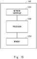
- Fig. 15 is a block diagram showing a configuration example of a node apparatus 140.
- the node apparatus 140 shows a configuration example of the relay apparatus 10 and the relay apparatus 30.
- the node apparatus 140 includes a network interface 1201, a processor 1202, and a memory 1203.
- the network interface 1201 is used for communication with other network node apparatuses constituting a communication system.
- the network interface 1201 may include, for example, a network interface card (NIC) in conformity with IEEE 802.3 series.
- NIC network interface card
Landscapes
- Engineering & Computer Science (AREA)
- Computer Networks & Wireless Communication (AREA)
- Signal Processing (AREA)
- Computer Security & Cryptography (AREA)
- Synchronisation In Digital Transmission Systems (AREA)
- Data Exchanges In Wide-Area Networks (AREA)
Abstract
Description
- The present disclosure relates to a relay apparatus, a communication system, and a failure detection method. For example, the present disclosure relates to a relay apparatus that transmits synchronization information through a network, a communication system, and a failure detection method.
- A GNSS (Global Navigation Satellite System) receiver receives a signal (a synchronizing signal) broadcasted from a GNSS satellite in order to obtain synchronization of time, which is necessary to use a GPS (Global Positioning System) or the like. The GNSS receiver can output a timing signal synchronized with a UTC (Coordinated Universal Time) by using the synchronizing signal broadcasted from the GNSS satellite.
- Further, in some cases, in order to enable a communication apparatus located in a place where it cannot receive a synchronizing signal from a GNSS satellite to use the synchronizing signal, a GNSS receiver that has received the synchronizing signal from the GNSS satellite transmits the received synchronizing signal to the communication apparatus through a packet network.
- However, the synchronizing signal that has been transmitted through the packet network involves a transmission delay. Further, transmission delay values vary due to the traffic condition or the like in the packet network. Therefore, a communication apparatus needs to use a synchronizing signal while giving consideration to a transmission delay caused in a packet network.
- Note that in an IEEE1588v2 (IEEE1588-2008) network which is specified to perform phase synchronization using packet data (a synchronizing packet), it is specified that a Transparent Clock apparatus is used to reduce transmission delays caused in transmission apparatuses and relay apparatuses which constitute the network. The Transparent Clock apparatus writes a duration for which an incoming synchronizing packet has remained in the Transparent Clock apparatus into a correction field of that synchronizing packet and then transmits the synchronizing packet in which the correction field has been updated to a communication apparatus. The synchronizing packet is, for example, a PTP Packet specified in the IEEE1588-2008. Further, the correction field is, for example, a correctionField specified in the IEEE1588-2008.
-
Patent Literature 1 discloses that in a communication system in which a relay apparatus is disposed between a communication apparatus on a transmitting side and a communication apparatus on a receiving side, the communication apparatuses on the transmitting and receiving sides synchronize their times with each other. Specifically, the communication apparatus on the transmitting side transmits data in which a transmitting time and a delay time of a transmission line to the relay apparatus are set to the relay apparatus. Further, the relay apparatus transmits data in which a delay time of a transmission line to the communication apparatus on the receiving side is set to the communication apparatus on the receiving side. The communication apparatus on the receiving side synchronizes its time by using the time information and the transmission-line delay times set in the received data. - Patent Literature 1: Japanese Unexamined Patent Application Publication No.
2013-168811 - When a failure has occurred in the relay apparatus disclosed in
Patent Literature 1, an appropriate transmission-line delay time or the like may not be set in data that is transmitted from the relay apparatus to the communication apparatus on the receiving side. That is, in the case where the communication apparatuses on the transmitting and receiving sides synchronize their times with each other in a state in which a failure has occurred in the relay apparatus, when the communication apparatus on the receiving side receives data in which an accurate transmission-line delay time or the like is not set, it cannot perform a normal time synchronizing process. - However,
Patent Literature 1 does not disclose any operation for detecting a failure in the relay apparatus even when the failure has occurred inside the apparatus. Therefore, there is a problem that when a failure has occurred in the relay apparatus, the communication apparatus on the receiving side continues an incorrect time synchronizing process. - An object of the present disclosure is to provide a relay apparatus, a communication system, and a failure detection method capable of detecting a failure that occurs in the relay apparatus.
- A relay apparatus according to a first aspect of the present disclosure includes: a data reception unit configured to receive a synchronizing packet transmitted from a master apparatus, the synchronizing packet containing a time value and a time correction value for correcting the time value; an update unit configured to update the time correction value based on a processing time for the synchronizing packet; and a determination unit configured to determine whether or not a failure has occurred in a functional block related to a process for updating the time correction value by using a result of a comparison between a corrected time value and a reference time value, the corrected time value having been corrected by using the updated time correction value.
- A communication system according to a second aspect of the present disclosure includes: a master apparatus configured to transmit a synchronizing packet containing a time value and a time correction value for correcting the time value; a secondary apparatus configured to reproduce a time value synchronized with the time value indicated by the master apparatus by using the synchronizing packet; and a relay apparatus configured to relay the synchronizing packet transmitted/received between the master apparatus and the secondary apparatus, in which the relay apparatus includes: a data reception unit configured to receive the synchronizing packet transmitted from the master apparatus; an update unit configured to update the time correction value based on a processing time for the synchronizing packet; and a determination unit configured to determine whether or not a failure has occurred in a functional block related to a process for updating the time correction value by using a result of a comparison between a corrected time value and a reference time value, the corrected time value having been corrected by using the updated time correction value.
- A failure detection method according to a third aspect of the present disclosure includes: receiving a synchronizing packet transmitted from a master apparatus, the synchronizing packet containing a time value and a time correction value for correcting the time value; updating the time correction value based on a processing time for the synchronizing packet; and determining whether or not a failure has occurred in a functional block related to a process for updating the time correction value by using a result of a comparison between a corrected time value and a reference time value, the corrected time value having been corrected by using the updated time correction value.
- According to the present disclosure, it is possible to provide a relay apparatus, a communication system, and a failure detection method capable of detecting a failure that occurs in the relay apparatus.
-
-
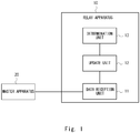
Fig. 1 is a configuration diagram of a relay apparatus according to a first embodiment; -
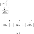
Fig. 2 is a configuration diagram of a communication system according to a second embodiment; -
Fig. 3 is a configuration diagram of a relay apparatus according to the second embodiment; -
Fig. 4 is a structure diagram of a synchronizing packet according to the second embodiment; -
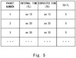
Fig. 5 is a table showing information managed by a determination unit according to the second embodiment; -
Fig. 6 is a table showing information managed by a determination unit according to the second embodiment; -
Fig. 7 shows a flow of a time correction field update process performed in an after-data-processing time correction unit according to the second embodiment; -
Fig. 8 shows a flow of a time correction field update process performed in a prior-to-data-processing time correction unit according to the second embodiment; -
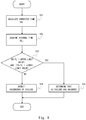
Fig. 9 shows a flow of a determination process performed in a determination unit according to the second embodiment; -
Fig. 10 is a configuration diagram of a relay apparatus according to a third embodiment; -
Fig. 11 is a configuration diagram of a relay apparatus according to a fourth embodiment; -
Fig. 12 is a configuration diagram of a relay apparatus according to a fifth embodiment; -
Fig. 13 is a configuration diagram of a relay apparatus according to a sixth embodiment; -
Fig. 14 is a configuration diagram of a relay apparatus according to a seventh embodiment; and -
Fig. 15 is a configuration diagram of a relay apparatus according to each embodiment. - Embodiments according to the present disclosure are explained with reference to the drawings. A configuration example of a
relay apparatus 10 according to a first embodiment of the present disclosure is explained with reference toFig. 1 . Therelay apparatus 10 may be a computer apparatus that operates by having a processor execute a program stored in a memory. - The
relay apparatus 10 includes adata reception unit 11, anupdate unit 12, and adetermination unit 13. Each of the components constituting therelay apparatus 10 may be software, a module, or the like that operates by having a processor execute a program stored in a memory. Alternatively, each of the components constituting therelay apparatus 10 may be hardware such as a chip or a circuit. - The
data reception unit 11 receives a synchronizing packet transmitted from amaster apparatus 20. The synchronizing packet contains a time value and a time correction value for correcting the time value. When IEEE1588-2008, for example, is applied to therelay apparatus 10, the time value is a Timestamp or an originTimestamp specified in the IEEE1588-2008. Further, when the IEEE1588-2008, for example, is applied to therelay apparatus 10, the time correction value is a value set in the correctionField. - The
master apparatus 20 may be a computer apparatus that operates by having a processor execute a program stored in a memory. Thedata reception unit 11 may receive a synchronizing packet transmitted from themaster apparatus 20 through a network. Thedata reception unit 11 outputs the received synchronizing packet to theupdate unit 12. - The
update unit 12 updates the time correction value based on a processing time for the synchronizing packet output from thedata reception unit 11. The synchronizing packet is transmitted to other devices or the like after undergoing packet processing performed in therelay apparatus 10. Therefore, for example, theupdate unit 12 may update the time correction value, which has been set in the synchronizing packet transmitted from themaster apparatus 20, by adding a packet processing time in therelay apparatus 10 to that time correction value. Theupdate unit 12 outputs the synchronizing packet in which the time correction value has been updated to thedetermination unit 13. - The
determination unit 13 determines whether or not a failure has occurred in a functional block related to the process for updating the time correction value by using a result of a comparison between a corrected time value, which has been corrected by using the updated time correction value, and a reference time value. When the IEEE1588-2008, for example, is applied to therelay apparatus 10, the reference time value is a local time specified in the IEEE1588-2008. - The corrected time value, which has been corrected by using the updated time correction value, is, for example, a value obtained by correcting the time value contained in the synchronizing packet transmitted from the
master apparatus 20 by using the updated time correction value. - The reference time value may be, for example, a time value output from a clock device provided in the
relay apparatus 10 or a time value or the like transmitted from a clock device disposed outside therelay apparatus 10. - The
determination unit 13 may determine that the process for updating the time correction value has been properly performed in therelay apparatus 10 when temporal progress of the corrected time value, which has been corrected by using the updated time correction value, (hereinafter referred to as the corrected time value) is substantially equal to temporal progress of the reference time value based on a comparison between the corrected time value and the reference time value. Further, thedetermination unit 13 may determine that the process for updating the time correction value has not been properly performed in therelay apparatus 10 when the temporal progress of the corrected time value differs from the temporal progress of the reference time value. The temporal progress may mean, for example, a lapse of time. - In this specification, the fact that the process for updating the time correction value has not been properly performed in the
relay apparatus 10 means that a failure has occurred in a functional block related to the process for updating the time correction value. Note that thedetermination unit 13 shown inFig. 1 may function as a verification unit that verifies whether or not the time correction value is normal. For example, thedetermination unit 13 verifies the normality of the time correction value by using a result of a comparison between the corrected time value and the reference time value. For example, thedetermination unit 13 may determine that the time correction value is normal when the temporal progress of the corrected time value is substantially equal to that of the reference time value, and determine that the time correction value is not normal when the temporal progress of the corrected time value is not substantially equal to that of the reference time value. - As explained above, the
relay apparatus 10 according to the first embodiment of the present disclosure can determine whether or not the process for updating the time correction value has been properly performed in therelay apparatus 10 itself by comparing the corrected time value with the reference time value. - By making it possible to detect a failure in the
relay apparatus 10, it is possible to determine whether or not the time synchronization, which has been performed by using the synchronizing packet transmitted from therelay apparatus 10, has been accurately performed. Further, by making it possible to detect a failure in therelay apparatus 10, it is possible to repair therelay apparatus 10, use other relay apparatuses, or take other countermeasures. - Next, a configuration example of a communication system according to a second embodiment of the present disclosure is explained with reference to
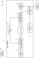
Fig. 2 . A communication system shown in the figure includes aGNSS satellite 60, aGNSS receiver 62, aMaster apparatus 40, arelay apparatus 30, and aSlave apparatus 50. - The
GNSS satellite 60 transmits a GNSS broadcast signal synchronized with a UTC. Further, the term GNSS is a general term for satellite positioning systems including GPS, GLONASS, Galileo, Compass, Quasi-Zenith Satellite System (QZSS), etc. TheGNSS receiver 62 receives a GNSS broadcast signal transmitted from theGNSS satellite 60. TheGNSS receiver 62 reproduces a synchronizing signal based on the GNSS broadcast signal and transmits the reproduced synchronizing signal to theMaster apparatus 40. Alternatively, the function in theGNSS receiver 62 and the function in theMaster apparatus 40 may be incorporated in the same apparatus. - The
Master apparatus 40 transmits a synchronizing packet to theSlave apparatus 50 through therelay apparatus 30. The synchronizing packet is, for example, a clock signal generated by using the GNSS broadcast signal. Note that theMaster apparatus 40 transmits a synchronizing signal by using, for example, a method specified in IEEE1588 (hereinafter called IEEE1588 transmission) or a Synchronous Ethernet (Registered Trademark) method (hereinafter called a SyncE method). The IEEE1588 transmission and the SyncE transmission are performed through an Ethernet (Registered Trademark). Further, the IEEE1588 may also be referred to as a PTP (Precision Time Protocol). The method specified in the IEEE1588 includes, for example, updated versions such as IEEE1588Version2 (IEEE1588v2). - The
relay apparatus 30 is, for example, an apparatus that is disposed in a packet network and transmits packet data through an Ethernet or a radio communication network. The figure shows a configuration in which onerelay apparatus 30 is disposed in a packet network between theMaster apparatus 40 and theSlave apparatus 50. However, a plurality ofrelay apparatuses 30 may be disposed in the packet network between theMaster apparatus 40 and theSlave apparatus 50. - The
relay apparatus 30 receives a synchronizing packet transmitted from theMaster apparatus 40. Further, therelay apparatus 30 incorporates a data processing time in therelay apparatus 30 itself into a time correction field of the synchronizing packet. That is, therelay apparatus 30 updates the time correction field of the synchronizing packet. Therelay apparatus 30 transmits the synchronizing packet in which the time correction field has been updated to theSlave apparatus 50. In the case in which a plurality of relay apparatuses are disposed in the packet network, therelay apparatus 30 may receive a synchronizing packet transmitted from other relay apparatuses. Further, therelay apparatus 30 may transmit an updated synchronizing packet to other relay apparatuses. - The
Slave apparatus 50 receives the synchronizing packet which has been transmitted through therelay apparatus 30. Further, theSlave apparatus 50 generates synchronized time information that is in synchronization with time information generated by theGNSS receiver 62, theMaster apparatus 40, or the like by using the received synchronizing packet. For the generation of the synchronized time information, the above-described method specified in the IEEE1588 or the like may be used. Alternatively, other methods may be used. - Next, a configuration example of the
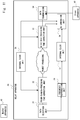
relay apparatus 30 according to the second embodiment of the present disclosure is explained with reference toFig. 3 . Therelay apparatus 30 includes adata reception unit 31, a prior-to-data-processingtime correction unit 32, an after-data-processingtime correction unit 33, adata transmission unit 34, aninternal clock unit 35, and adetermination unit 36. Thedata reception unit 31 corresponds to thedata reception unit 11 shown inFig. 1 . The prior-to-data-processingtime correction unit 32 and the after-data-processingtime correction unit 33 correspond to theupdate unit 12 shown inFig. 1 . Thedetermination unit 36 corresponds to thedetermination unit 13 shown inFig. 1 . - The
data reception unit 31 receives a synchronizing packet transmitted from theMaster apparatus 40. For example, thedata reception unit 31 receives a synchronizing packet transmitted from theMaster apparatus 40 through a packet network. At least one relay apparatus may be disposed between theMaster apparatus 40 and thedata reception unit 31. That is, thedata reception unit 31 may receive a synchronizing packet transmitted from theMaster apparatus 40 without any intervention by a relay apparatus or the like disposed in the network, or may receive a synchronizing packet transmitted through a plurality of relay apparatuses or the like disposed in the network. Thedata reception unit 31 outputs the received synchronizing packet to the prior-to-data-processingtime correction unit 32. - An example of a structure of a synchronizing packet is explained hereinafter with reference to
Fig. 4 . A synchronizing packet that theMaster apparatus 40 transmits to therelay apparatus 30 contains a header, a payload, a time field, and a time correction field. The header and the payload are the same as those in a commonly-used frame or a commonly-used packet and therefore there detailed explanations are omitted. The time field and the time correction field may be defined as a part of the header, or may be defined as a part of ordinary data in the payload. - In the time field, for example, a time value indicating a time at which the
Master apparatus 40 transmits the synchronizing packet is set. Further, in the time correction field, for example, a time correction value for correcting the time value for a transmission delay of the synchronizing packet caused in the packet network, a processing delay thereof caused in each relay apparatus, and the like is set. - Referring
Fig. 3 again, the prior-to-data-processingtime correction unit 32 extracts the time correction value set in the time correction field of the synchronizing packet. The prior-to-data-processingtime correction unit 32 subtracts information indicating a time at which the synchronizing packet is received from the extracted time correction value and thereby updates the time correction field. The time at which the synchronizing packet is received may be, for example, a time at which the prior-to-data-processingtime correction unit 32 receives the synchronizing packet from thedata reception unit 31. - The prior-to-data-processing
time correction unit 32 outputs the synchronizing packet in which the time correction field has been updated to a circuit, a functional block, or the like that performs data processing. The functional block is, for example, a function by which processing is performed by having a processor execute a program. For example, the functional block may be a packet switch function or the like. The circuit, the functional block, or the like that performs data processing may be, for example, a process for controlling a transmission line or the like of a synchronizing packet in the packet network, or may be a process for information set in other packet layers or a process for information set in a layer higher than the packet layer. The data processing may be, for example, referred to as packet processing. - The synchronizing packet, for which data processing has been performed in the circuit or the like that performs data processing, is output to the after-data-processing
time correction unit 33. The after-data-processingtime correction unit 33 extracts the time correction value set in the time correction field of the output synchronizing packet. The after-data-processingtime correction unit 33 updates the time correction field by adding information indicating a time that is later than the execution of the data processing for the synchronizing packet to the extracted time correction value. - The time later than the execution of the data processing for the synchronizing packet may be, for example, a time at which the after-data-processing
time correction unit 33 receives the synchronizing packet for which the data processing has been performed. - The after-data-processing
time correction unit 33 outputs the synchronizing packet in which the time correction field has been updated to thedata transmission unit 34 and thedetermination unit 36. Thedata transmission unit 34 transmits the synchronizing packet output from the after-data-processingtime correction unit 33 to theSlave apparatus 50. - For example, the
data transmission unit 34 transmits the synchronizing packet to theSlave apparatus 50 through the packet network. At least one relay apparatus may be disposed between thedata transmission unit 34 and theSlave apparatus 50. That is, theSlave apparatus 50 may receive a synchronizing packet transmitted from thedata transmission unit 34 without any intervention by a relay apparatus disposed in the network, or may receive a synchronizing packet transmitted through a plurality of relay apparatuses or the like disposed in the network. - The
internal clock unit 35 generates a clock signal that is used in a circuit, a functional block, and the like disposed in therelay apparatus 30. Theinternal clock unit 35 may be, for example, an oscillator. For example, theinternal clock unit 35 outputs the clock signal to the prior-to-data-processingtime correction unit 32, the after-data-processingtime correction unit 33, and thedetermination unit 36. The prior-to-data-processingtime correction unit 32, the after-data-processingtime correction unit 33, and thedetermination unit 36 can recognize the current time by using the clock signal output from theinternal clock unit 35. - For example, the
internal clock unit 35 outputs a clock signal in which a counter value is set to the prior-to-data-processingtime correction unit 32, the after-data-processingtime correction unit 33, and thedetermination unit 36. A counter value that increases according to the lapse of time is set in the clock signal. In this case, the prior-to-data-processingtime correction unit 32 subtracts a counter value indicating the current time from a counter value set in a time correction field of a synchronizing signal output from thedata reception unit 31. For example, when the counter value indicating the current time is Ta, the prior-to-data-processingtime correction unit 32 sets a value -Ta in the time correction field. - When the after-data-processing
time correction unit 33 receives the synchronizing packet, for which the packet processing has been performed, it adds the counter value indicating the current time to the counter value set in the time correction field. For example, when the counter value indicating the current time is Tb, the after-data-processingtime correction unit 33 sets a value expressed by "-Ta+Tb" in the time correction field. Note that it is assumed that a value -Ta had been set in the time correction field. The value "Tb-Ta" indicates a packet processing time. That is, the packet processing time for the synchronizing packet in therelay apparatus 30 is set in the time correction field of that synchronizing packet. The value "-Ta+Tb" set in the time correction field of the synchronizing packet is referred to as a time correction value. - In some cases, the
relay apparatus 30 receives a synchronizing packet in which a time correction field has been updated from other relay apparatuses. It is assumed that, in such cases, a time correction value Tn calculated in the other relay apparatus has been set in the time correction field. When the time correction value Tn is set in the time correction field, the prior-to-data-processingtime correction unit 32 changes the value set in the time correction field to a value "Tn-Ta". Further, when the after-data-processingtime correction unit 33 receives the synchronizing packet in which the value "Tn-Ta" is set in the time correction field, it changes the value in the time correction field to a value "Tn-Ta+Tb". - In the above explanation, an example in which the prior-to-data-processing
time correction unit 32 subtracts a value Ta from a value set in the time correction field is shown. Further, the prior-to-data-processingtime correction unit 32 may add a delay time Dx indicating a difference between a time at which the prior-to-data-processingtime correction unit 32 receives the synchronizing packet and a time at which thedata reception unit 31 receives the synchronizing packet to the value of the time correction field. That is, the delay time Dx indicates a transmission delay that is caused when the synchronizing packet is transmitted from thedata reception unit 31 to the prior-to-data-processingtime correction unit 32. - The delay time Dx is a value intrinsic to the
relay apparatus 30 and is a fixed value that is unchanged for different synchronizing packets. Therefore, the prior-to-data-processingtime correction unit 32 may add a delay time Dx that is stored therein in advance to the value of the time correction field. That is, the prior-to-data-processingtime correction unit 32 may add a value "Dx-Ta" to the value of the time correction field. In the case in which the prior-to-data-processingtime correction unit 32 does not store the delay time Dx in advance, every time the prior-to-data-processingtime correction unit 32 receives a synchronizing packet, it may calculate a transmission delay that is caused when the synchronizing packet is transmitted from thedata reception unit 31 to the prior-to-data-processingtime correction unit 32. - The after-data-processing
time correction unit 33 may add a delay time Dy indicating a transmission delay between the after-data-processingtime correction unit 33 and thedata transmission unit 34 to the value of the time correction field. For example, the delay time Dy may be a time indicating a difference between a time at which the after-data-processingtime correction unit 33 outputs a synchronizing packet and a time at which thedata transmission unit 34 transmits that synchronizing packet to other relay apparatuses or to theSlave apparatus 50 - Similarly to the delay time Dx, the delay time Dy is a value intrinsic to the
relay apparatus 30 and is a fixed value that is unchanged for different synchronizing packets. Therefore, the after-data-processingtime correction unit 33 may add a delay time Dy that is stored therein in advance to the value of the time correction field. That is, the prior-to-data-processingtime correction unit 32 may add a value "Dy+Tb" to the value of the time correction field. In other words, a value "Dx-Ta+Dy+Tb" is set in the time correction field. As therelay apparatus 30 adds the values Dx and Dy to the value of the time correction field, the packet processing time in therelay apparatus 30 and the transmission delay in the apparatus are incorporated into the time correction field. - The
Slave apparatus 50 can use the value "Dx-Ta+Dy+Tb" set in the time correction field of the synchronizing packet received from therelay apparatus 30 as a packet processing time or a data processing time in therelay apparatus 30 and thereby correct the synchronized time information. - The
determination unit 36 generates an internal time value by using the clock signal output from theinternal clock unit 35. The internal time value is a time value that is used in each functional block in therelay apparatus 30, which has received the clock signal output from theinternal clock unit 35, in a synchronous manner. Further, thedetermination unit 36 corrects the time value set in the time field of the synchronizing packet output from the after-data-processingtime correction unit 33 by using the time correction value set in the time correction field of the synchronizing packet. - Further, the
determination unit 36 manages the internal time value indicating the time at which the synchronizing packet is received and the time value which has been corrected by using the time correction value while associating them with each other. Thedetermination unit 36 determines whether or not a failure has occurred in a functional block related to a process for updating the time correction value. Specifically, thedetermination unit 36 determines whether or not a failure has occurred in the prior-to-data-processingtime correction unit 32, the after-data-processingtime correction unit 33, and a circuit or a functional block that performs packet processing for the synchronizing packet. The information managed by thedetermination unit 36 is explained hereinafter with reference toFig. 5 . - The packet number in
Fig. 5 indicates an order in which thedetermination unit 36 has received synchronizing packets output from the after-data-processingtime correction unit 33. The internal time (TL) indicates times at which the synchronizing packets are received. The corrected time (TO) indicates times that are obtained by correcting time values (Ti) set in time fields of synchronizing packets by using time correction values set in time correction fields of the synchronizing packets. For example, a corrected time TO may be expressed as "TO=Ti+(-Ta+Tb)" or "TO=Ti+(Dx-Ta+Dy+Tb)". The value "TO-TL" indicates a difference between the corrected time value and the internal time value. - Next, a determination process performed by the
determination unit 36 is explained. For example, thedetermination unit 36 may determine whether or not temporal progress of the corrected time value is substantially equal to temporal progress of the internal time value by comparing the value "TO-TL" with a threshold. - For example, the
determination unit 36 may define an upper limit threshold as 10 and define a lower limit threshold as 2. In this case, thedetermination unit 36 determines whether or not the value "TO-TL" satisfies a conditional expression. For example, thedetermination unit 36 may determine that the temporal progress of the corrected time value is substantially equal to that of the internal time value when the value "TO-TL" satisfies a condition "(TO-TL < Upper limit value: 10) and (TO-TL > Lower limit value: 2)". - In the example shown in
Fig. 5 , since all of the values "TO-TL" satisfy the conditional expression, thedetermination unit 36 determines that the temporal progress of the corrected time values is substantially equal to that of the internal time values. That is, thedetermination unit 36 determines that no failure has occurred in the prior-to-data-processingtime correction unit 32, the after-data-processingtime correction unit 33, and the circuit or the functional block that performs packet processing for synchronizing packets. - Next, a determination process performed by the
determination unit 36 is explained by using information shown inFig. 6 . The value "TO-TL" for thepacket number 1 shown inFig. 6 satisfies the conditional expression. However, regarding thepacket number 2, the value "TO-TL" is larger than the upper limit value 10 (TO-TL > Upper limit value: 10). Further, the value "TO-TL" for thepacket number 3 is also larger than the upper limit value 10 (TO-TL > Upper limit value: 10). Therefore, the values "TO-TL" for thepacket numbers determination unit 36 determines that a failure has occurred in at least one of the prior-to-data-processingtime correction unit 32, the after-data-processingtime correction unit 33, and the circuit or the functional block that performs packet processing for synchronizing packets. - In the above explanation, the
determination unit 36 determines whether or not temporal progress of the corrected time value is substantially equal to that of the internal time value by using the value "TO-TL". However, thedetermination unit 36 may perform a determination process by using a value other than the value "TO-TL". - For example, the
determination unit 36 may determine whether a value calculated by "(TO for packet number 2) - (TO for packet number 1)" is equal to a value calculated by "(TL for packet number 2) - (TL for packet number 1)", or whether it falls within a predetermined threshold range. That is, thedetermination unit 36 may determine whether or not temporal progress of the corrected time value is substantially equal to that of the internal time value by using a difference between internal times TL of packets that are received at different timings and a difference between corrected times TL of these packets. - Next, a flow of a process for updating a time correction field in the prior-to-data-processing
time correction unit 32 according to the second embodiment of the present disclosure is explained with reference toFig. 7 . Firstly, the prior-to-data-processingtime correction unit 32 receives a synchronizing packet output from the data reception unit 31 (S11). - Next, the prior-to-data-processing
time correction unit 32 subtracts a time Ta indicating the current time from a value set in the time correction field of the synchronizing packet (S12). When no value is set in the time correction field, the prior-to-data-processingtime correction unit 32 sets a value -Ta in the time correction field, whereas when a value Tn is already set in the time correction field, the prior-to-data-processingtime correction unit 32 sets a value "Tn-Ta" in the time correction field. - Next, the prior-to-data-processing
time correction unit 32 outputs the synchronizing packet, in which the time correction field has been updated, to a circuit or a functional block that performs packet processing for the synchronizing packet (S13). - When the prior-to-data-processing
time correction unit 32 subtracts the time Ta in the step S12, it may add a delay time Dx in addition to the subtraction. - Next, a flow of a process for updating a time correction field in the after-data-processing
time correction unit 33 according to the second embodiment of the present disclosure is explained with reference toFig. 8 . Firstly, the after-data-processingtime correction unit 33 acquires a synchronizing packet for which packet processing has already been performed (S21). - Next, the after-data-processing
time correction unit 33 adds a time Tb indicating the current time to a value set in the time correction field of the synchronizing packet (S22). As the after-data-processingtime correction unit 33 adds the time Tb, a value "-Ta+Tb" or a value "Tn-Ta+Tb", for example, may be set in the time correction field. - The after-data-processing
time correction unit 33 outputs the synchronizing packet, in which the time correction field has been updated, to thedata transmission unit 34 and the determination unit 36 (S23). - When the after-data-processing
time correction unit 23 adds the time Tb in the step S22, it may add a delay time Dy, too. - Next, a flow of a determination process in the
determination unit 36 according to the second embodiment of the present disclosure is explained with reference toFig. 9 . Firstly, thedetermination unit 36 acquires a synchronizing packet for which packet processing has already been performed and calculates a corrected time (TO) (S31). Next, thedetermination unit 36 acquires an internal time (TL) indicating a timing at which the synchronizing packet is acquired (S32). Note that althoughFig. 9 shows that the step S32 is performed after the step S31, the steps S31 and S32 may be simultaneously performed in practice. - Next the
determination unit 36 determines whether or not a condition "Lower limit threshold < TO-TL < Upper limit threshold" is satisfied (S33). When thedetermination unit 36 determines that the value "TO-TL" does not satisfy the condition "Lower limit threshold < TO-TL < Upper limit threshold", it determines that a failure has occurred in at least one of the prior-to-data-processingtime correction unit 32, the after-data-processingtime correction unit 33, and the circuit or the functional block that performs packet processing for the synchronizing packet (S34). When thedetermination unit 36 determines that the value "TO-TL" satisfies the condition "Lower limit threshold < TO-TL < Upper limit threshold", it determines that no failure has occurred in the prior-to-data-processingtime correction unit 32, the after-data-processingtime correction unit 33, and the circuit or the functional block that performs packet processing for the synchronizing packet (S35). - As explained above, the
relay apparatus 30 according to the second embodiment of the present disclosure can determine whether or not a failure has occurred in at least one of the prior-to-data-processingtime correction unit 32, the after-data-processingtime correction unit 33, and the circuit or the functional block that performs packet processing for synchronizing packets. - Further, in the step S34, the
determination unit 3 may detect an occurrence of a failure when thedetermination unit 36 determines that the condition "Lower limit threshold < TO-TL < Upper limit threshold" is not satisfied for a predetermined number of synchronizing packets or larger. - Further, the
relay apparatus 30 may transmit a result of the determination in thedetermination unit 36 to an apparatus other than therelay apparatus 30. An example of the apparatus other than therelay apparatus 30 may be an apparatus that monitors the whole network such as a network management apparatus. Alternatively, therelay apparatus 30 may display the result of the determination in thedetermination unit 36 in a display unit such as a liquid-crystal screen (not shown) provided in therelay apparatus 30, or output a sound indicating the determination result. - Next, a configuration example of a
relay apparatus 30 according to a third embodiment of the present disclosure is explained with reference toFig. 10 . Therelay apparatus 30 shown inFig. 10 includes an additionalinternal clock unit 37 compared to therelay apparatus 30 shown inFig. 3 . Detailed explanations of components of therelay apparatus 30 shown inFig. 10 that are similar to those of therelay apparatus 30 shown inFig. 3 are omitted. - The
internal clock unit 37 outputs a clock signal different from the clock signal output by theinternal clock unit 35. In other words, theinternal clock unit 37 operates independently of theinternal clock unit 35. Theinternal clock unit 37 outputs the clock signal to thedetermination unit 36. Thedetermination unit 36 generates an internal time value at which it receives a synchronizing packet output from the after-data-processingtime correction unit 33 by using the clock signal output from theinternal clock unit 37. - The
determination unit 36 calculates a corrected time (TO) by using the synchronizing packet in which a time correction value has been updated based on the clock signal output from theinternal clock unit 35. Further, thedetermination unit 36 calculates an internal time (TL) by using the clock signal output from theinternal clock unit 37. - When a value "TO-TL" does not satisfy a conditional expression "Lower limit threshold < TO-TL < Upper limit threshold", the
determination unit 36 can determine that there is a possibility that a failure has occurred in theinternal clock unit 35, in addition to in the prior-to-data-processingtime correction unit 32, the after-data-processingtime correction unit 33, and the circuit or the functional block that performs packet processing for synchronizing packets. However, this determination is made on the assumption that theinternal clock unit 37 is properly operating. - As explained above, the
determination unit 36 of therelay apparatus 30 according to the third embodiment of the present disclosure can calculate an internal time value by using a clock signal different from the clock signal used for the updating of the time correction value. In this way, thedetermination unit 36 can determine that there is a possibility that a failure has occurred in theinternal clock unit 35, in addition to in the prior-to-data-processingtime correction unit 32, the after-data-processingtime correction unit 33, and the circuit or the functional block that performs packet processing for synchronizing packets. - Next, a configuration example of a
relay apparatus 30 according to a fourth embodiment of the present disclosure is explained with reference toFig. 11 . Therelay apparatus 30 shown inFig. 11 includes an additionalfrequency reproduction unit 38 compared to therelay apparatus 30 shown inFig. 10 . Detailed explanations of components of therelay apparatus 30 shown inFig. 11 that are similar to those of therelay apparatus 30 shown inFig. 10 are omitted. - The
frequency reproduction unit 38 reproduces a frequency used in theMaster apparatus 40 by using a synchronizing packet transmitted from theMaster apparatus 40. Specifically, thefrequency reproduction unit 38 reproduces the frequency by using a method specified in IEEE1588 or IEEE1588Version2 (hereinafter referred to as IEEE1588). For example, thefrequency reproduction unit 38 reproduces the frequency by using information on intervals between receptions of synchronization information (packet data) transmitted according to the IEEE1588 method. When IEEE1588-2008, for example, is applied to therelay apparatus 30, the receiving interval information is an Interval of received packet specified in the IEEE1588-2008. Instead of using the IEEE1588 method, an ACR (AdaptiveClockRecovery) specified in ITU-T G.8265.1 or the like may be used for the reproduction of a frequency using receiving interval information. - Further, the receiving interval of packet data may vary among a plurality of packet data due to a congestion state or the like of the network. In such a case, the receiving interval of packet data may be calculated by statistically analyzing receiving intervals over a plurality of packet data. For example, an average value of a plurality of receiving intervals may be calculated. Alternatively, a median of a plurality of receiving intervals may be calculated.
- The
frequency reproduction unit 38 outputs the reproduced frequency information to theinternal clock unit 37. Theinternal clock unit 37 generates a clock signal based on the frequency information output from thefrequency reproduction unit 38. That is, theinternal clock unit 37 generates a clock signal that is synchronized with the frequency information output from thefrequency reproduction unit 38. Theinternal clock unit 37 outputs a counter value that has been incremented according to clock timings determined based on the frequency information output from thefrequency reproduction unit 38 to thedetermination unit 36. - As explained above, the
internal clock unit 37 can reproduce the frequency used in theMaster apparatus 40 by using a synchronizing packet transmitted from theMaster apparatus 40. In this way, theinternal clock unit 37 can achieve accuracy comparable to that of the clock in theMaster apparatus 40. Since theinternal clock unit 37 synchronizes its frequency with the frequency used in theMaster apparatus 40, it is unnecessary to use a highly-accurate clock generation device, thus making it possible to reduce the cost of therelay apparatus 30. - Next, a configuration example of a
relay apparatus 30 according to a fifth embodiment of the present disclosure is explained with reference toFig. 12 . Therelay apparatus 30 shown inFig. 12 includes an additionalfrequency reproduction unit 39 compared to therelay apparatus 30 shown inFig. 3 . - Similarly to the
frequency reproduction unit 38 shown inFig. 11 , thefrequency reproduction unit 39 reproduces a frequency used in theMaster apparatus 40 by using a synchronizing packet transmitted from theMaster apparatus 40. Thefrequency reproduction unit 39 outputs the reproduced frequency information to theinternal clock unit 35. Theinternal clock unit 35 generates a clock signal based on the frequency information output from thefrequency reproduction unit 39. That is, theinternal clock unit 35 generates a clock signal that is synchronized with the frequency information output from thefrequency reproduction unit 39. Theinternal clock unit 35 outputs a counter value that has been incremented according to clock timings determined based on the frequency information output from thefrequency reproduction unit 39 to the prior-to-data-processingtime correction unit 32 and the after-data-processingtime correction unit 33. - In this way, the
internal clock unit 35 generates a clock signal that is synchronized with the clock signal in theMaster apparatus 40. - Further, the
determination unit 36 receives a clock signal transmitted from aGNSS apparatus 70 disposed outside therelay apparatus 30, instead of receiving a clock signal from theinternal clock unit 35. In this way, assuming that theGNSS apparatus 70 is properly operating, thedetermination unit 36 can detect a failure in theMaster apparatus 40 and a failure in a communication line between theMaster apparatus 40 and therelay apparatus 30, in addition to a failure in the prior-to-data-processingtime correction unit 32, the after-data-processingtime correction unit 33, the circuit or the functional block that performs packet processing for synchronizing packets, and theinternal clock unit 35. - As explained above, the
relay apparatus 30 shown inFig. 12 can detect a failure in theMaster apparatus 40 and a failure in the communication line between theMaster apparatus 40 and therelay apparatus 30, in addition to a failure that occurs inside therelay apparatus 30. - Next, a configuration example of a
relay apparatus 30 according to a sixth embodiment of the present disclosure is explained with reference toFig. 13 . In therelay apparatus 30 shown inFig. 13 , thedetermination unit 36 receives a synchronizing packet output from thedata reception unit 31. - That is, the
determination unit 36 receives a synchronizing packet whose time correction value has not been updated yet in the prior-to-data-processingtime correction unit 32 and the after-data-processingtime correction unit 33. Thedetermination unit 36 manages a time value set in a time field in the synchronizing packet and an internal time value indicating a timing at which it receives the synchronizing packet output from thedata reception unit 31 while associating them with each other. The internal time value is determined based on a clock signal output from theinternal clock unit 35. - The
determination unit 36 determines whether or not a difference (Ti-TL) between the time value (Ti) set in the time field of the synchronizing packet and the internal time value (TL) satisfies a condition that "(Ti-TL < Upper limit value) and (Ti-TL > Lower limit value)". When thedetermination unit 36 determines that the difference does not satisfy the condition that "(Ti-TL < Upper limit value) and (Ti-TL > Lower limit value)", it determines that a failure has occurred in theMaster apparatus 40 or in a communication line between theMaster apparatus 40 and therelay apparatus 30. - As explained above, the
relay apparatus 30 shown inFig. 13 can determine whether or not a failure has occurred outside therelay apparatus 30 by using a synchronizing packet whose time correction field has not been updated yet. Further, thedetermination unit 36 can determine whether or not there is an occurrence of a failure by using a synchronizing packet whose time correction field has already been updated. In this way, therelay apparatus 30 shown inFig. 13 can determine whether or not there is an occurrence of a failure inside therelay apparatus 30 and outside therelay apparatus 30. - Next, a configuration example of a
relay apparatus 30 according to a seventh embodiment of the present disclosure is explained with reference toFig. 14. Fig. 14 shows that the after-data-processingtime correction unit 33 is formed by using one hardware component. The hardware component is, for example, an IC chip or the like. Anaddition circuit 71 and aconversion circuit 72 are disposed in the IC chip which constitutes the after-data-processingtime correction unit 33. - The
addition circuit 71 adds a value Tb to the value of the time correction field of the synchronizing packet. Theconversion circuit 72 converts a MAC frame output from theaddition circuit 71 into a physical signal. The physical signal is a signal transmitted through a transmission medium that is used to transmit data from thedata transmission unit 34 to theSlave apparatus 50. - In general, in the case in which the
addition circuit 71 and theconversion circuit 72 are formed by using one IC chip, when a MAC frame output from theaddition circuit 71 is output to thedetermination unit 36, it is necessary to change the configuration of the IC chip. Therefore, the IC chip constituting the after-data-processingtime correction unit 33 is not changed and anaddition circuit 73 is provided in an IC chip different from the IC chip for the after-data-processingtime correction unit 33. Further, the same data that is input to theaddition circuit 71 is input to theaddition circuit 73. Thedetermination unit 36 determines whether or not there is an occurrence of a failure by using a synchronizing packet whose time correction field is updated in theaddition circuit 73. - As explained above, the
determination unit 36 shown inFig. 14 can determine whether or not there is an occurrence of a failure by using a synchronizing packet output from theaddition circuit 73 that is disposed in hardware different from the hardware constituting the after-data-processingtime correction unit 33. In this way, even when the after-data-processingtime correction unit 33 has been already constructed by using one hardware component, it is possible to perform a determination process using thedetermination unit 36 without changing the after-data-processingtime correction unit 33. - Next, a configuration example of the
relay apparatus 10 and therelay apparatus 30 explained in the above-described plurality of embodiments is explained hereinafter with reference toFig. 15. Fig. 15 is a block diagram showing a configuration example of anode apparatus 140. Thenode apparatus 140 shows a configuration example of therelay apparatus 10 and therelay apparatus 30. As shown inFig. 15 , thenode apparatus 140 includes anetwork interface 1201, aprocessor 1202, and amemory 1203. Thenetwork interface 1201 is used for communication with other network node apparatuses constituting a communication system. Thenetwork interface 1201 may include, for example, a network interface card (NIC) in conformity with IEEE 802.3 series. - The
processor 1202 performs processes performed by thenode apparatus 140 explained with reference to the sequence diagrams and the flowcharts in the above-described embodiments by loading a software module from thememory 1203 and executing the loaded software module. Theprocessor 1202 may be, for example, a microprocessor, an MPU, a CPU, a DSP, or an FPGA. Theprocessor 1202 may include a plurality of processors. - The
memory 1203 is formed by a combination of a volatile memory and a nonvolatile memory. Thememory 1203 may include a storage disposed apart from theprocessor 1202. In this case, theprocessor 1202 may access thememory 1203 through an I/O interface (not shown). - In the example shown in
Fig. 15 , thememory 1203 is used to store a group of software modules. Theprocessor 1202 can perform processes performed by thenode apparatus 140 explained in the above-described embodiments by loading the group of software modules from thememory 1203 and executing the loaded software modules. - As explained above with reference to
Fig. 15 , each of the processors included in therelay apparatus 10 and therelay apparatus 30 executes one or a plurality of programs including a group of instructions to cause a computer to perform an algorithm explained above with reference to the drawings. - In the above-described examples, the program can be stored and provided to a computer using any type of non-transitory computer readable media. Non-transitory computer readable media include any type of tangible storage media. Examples of non-transitory computer readable media include magnetic storage media (such as floppy disks, magnetic tapes, hard disk drives, etc.), optical magnetic storage media (e.g., magneto-optical disks), CD-ROM (compact disc read only memory), CD-R (compact disc recordable), CD-R/W (compact disc rewritable), and semiconductor memories (such as mask ROM, PROM (programmable ROM), EPROM (erasable PROM), flash ROM, RAM (random access memory), etc.). The program may be provided to a computer using any type of transitory computer readable media. Examples of transitory computer readable media include electric signals, optical signals, and electromagnetic waves. Transitory computer readable media can provide the program to a computer via a wired communication line (e.g., electric wires, and optical fibers) or a wireless communication line.
- Note that the present disclosure is not limited to the above-described embodiments and can be modified as appropriate without departing from the spirit and scope of the present disclosure.
- Although the present disclosure is explained above with reference to embodiments, the present disclosure is not limited to the above-described embodiments. Various modifications that can be understood by those skilled in the art can be made to the configuration and details of the present disclosure within the scope of the present disclosure.
- This application is based upon and claims the benefit of priority from Japanese patent applications No.
2015-167411, filed on August 27, 2015 - The whole or part of the embodiments disclosed above can be described as, but not limited to, the following supplementary notes.
- A relay apparatus comprising:
- a data reception unit configured to receive a synchronizing packet transmitted from a master apparatus, the synchronizing packet containing a time value and a time correction value for correcting the time value;
- an update unit configured to update the time correction value based on a processing time for the synchronizing packet; and
- a determination unit configured to determine whether or not a failure has occurred in a functional block related to a process for updating the time correction value by using a result of a comparison between a corrected time value and a reference time value, the corrected time value having been corrected by using the updated time correction value.
- The relay apparatus described in
Supplementary note 1, wherein when the determination unit successively receives a plurality of synchronizing packets in each of which the time correction value has been updated and a difference between the corrected time value in a first synchronizing packet included in the plurality of synchronizing packets and a reference time value indicating a time at which the first synchronizing packet is received exceeds a predetermined threshold, the determination unit determines that a failure has occurred in the functional block related to the process for updating the time correction value. - The relay apparatus described in
Supplementary note
the determination unit uses an internal time value at which the synchronizing packet in which the time correction value has been updated is received as the reference time value. - The relay apparatus described in
Supplementary note - a first clock unit configured to supply an internal time to the update unit; and
- a second clock unit configured to supply an internal time to the determination unit, the second clock unit being different from the first clock unit, wherein
- the determination unit uses an internal time value at which the synchronizing packet in which the time correction value has been updated is received as the reference time value.
- The relay apparatus described in
Supplementary note - a first clock unit configured to supply an internal time to the update unit, wherein
- the determination unit determines a time at which the synchronizing packet in which the time correction value has been updated is received by using an internal time value supplied from outside of the relay apparatus, and uses the internal time value supplied from outside of the relay apparatus as the reference time value.
- The relay apparatus described in
Supplementary note 5, wherein the internal time value supplied from outside of the relay apparatus is determined based on a frequency reproduced by using the synchronizing packet transmitted through a physical layer. - The relay apparatus described in
Supplementary note - a first update unit configured to update the time correction value based on a processing time for the synchronizing packet;
- a data transmission unit configured to transmit the synchronizing packet output from the first update unit to a slave apparatus; and
- a second update unit configured to update the time correction value based on the processing time for the synchronizing packet, the second update unit being disposed in a hardware circuit different from a hardware circuit including the first update unit, wherein
- the determination unit determines whether or not a failure has occurred in the functional block related to the process for updating the time correction value by using a result of a comparison between a corrected time value and a reference time value, the corrected time value having been corrected by using a time correction value updated in the second update unit.
- The relay apparatus described in any one of
Supplementary notes 1 to 7, wherein the update unit updates the time correction value by subtracting a reception time value indicating a time at which the synchronizing packet is received in the data reception unit from the time correction value and then adding an after-processing time value indicating a time later than a time of processing for the synchronizing packet to the resultant time correction value. - The relay apparatus described in any one of
Supplementary notes 1 to 8, wherein when the determination unit determines that a failure has occurred in the functional block related to the process for updating the time correction value, it transmits a result of the determination to an apparatus different from the relay apparatus. - The relay apparatus described in any one of
Supplementary notes 1 to 8, wherein when the determination unit determines that a failure has occurred in the functional block related to the process for updating the time correction value, it outputs a result of the determination to at least one of a display unit configured to display the result of the determination and a sound output unit configured to output a sound indicating the result of the determination. - A relay apparatus comprising:
- a data reception unit configured to receive a synchronizing packet transmitted from a master apparatus, the synchronizing packet containing a time value and a time correction value for correcting the time value;
- an update unit configured to update the time correction value based on a processing time for the synchronizing packet; and
- a verification unit configured to verify whether or not the time correction value is normal.
- A communication system comprising:
- a master apparatus configured to transmit a synchronizing packet containing a time value and a time correction value for correcting the time value;
- a secondary apparatus configured to reproduce a time value synchronized with the time value indicated by the master apparatus by using the synchronizing packet; and
- a relay apparatus configured to relay the synchronizing packet transmitted/received between the master apparatus and the secondary apparatus, wherein
- the relay apparatus comprises:
- a data reception unit configured to receive the synchronizing packet transmitted from the master apparatus;
- an update unit configured to update the time correction value based on a processing time for the synchronizing packet; and
- a determination unit configured to determine whether or not a failure has occurred in a functional block related to a process for updating the time correction value by using a result of a comparison between a corrected time value and a reference time value, the corrected time value having been corrected by using the updated time correction value.
- A failure detection method comprising:
- receiving a synchronizing packet transmitted from a master apparatus, the synchronizing packet containing a time value and a time correction value for correcting the time value;
- updating the time correction value based on a processing time for the synchronizing packet; and
- determining whether or not a failure has occurred in a functional block related to a process for updating the time correction value by using a result of a comparison between a corrected time value and a reference time value, the corrected time value having been corrected by using the updated time correction value.
-
- 10
- RELAY APPARATUS
- 11
- DATA RECEPTION UNIT
- 12
- UPDATE UNIT
- 13
- DETERMINATION UNIT
- 20
- MASTER APPARATUS
- 30
- RELAY APPARATUS
- 31
- DATA RECEPTION UNIT
- 32
- PRIOR-TO-DATA-PROCESSING TIME CORRECTION UNIT
- 33
- AFTER-DATA-PROCESSING TIME CORRECTION UNIT
- 34
- DATA TRANSMISSION UNIT
- 35
- INTERNAL CLOCK UNIT
- 36
- DETERMINATION UNIT
- 37
- INTERNAL CLOCK UNIT
- 38
- FREQUENCY REPRODUCTION UNIT
- 39
- FREQUENCY REPRODUCTION UNIT
- 40
- Master APPARATUS
- 50
- Slave APPARATUS
- 60
- GNSS SATELLITE
- 62
- GNSS RECEIVER
- 71
- ADDITION CIRCUIT
- 72
- CONVERSION CIRCUIT
- 73
- ADDITION CIRCUIT
Claims (13)
- A relay apparatus comprising:data reception means for receiving a synchronizing packet transmitted from a master apparatus, the synchronizing packet containing a time value and a time correction value for correcting the time value;update means for updating the time correction value based on a processing time for the synchronizing packet; anddetermination means for determining whether or not a failure has occurred in a functional block related to a process for updating the time correction value by using a result of a comparison between a corrected time value and a reference time value, the corrected time value having been corrected by using the updated time correction value.
- The relay apparatus according to Claim 1, wherein when the determination means successively receives a plurality of synchronizing packets in each of which the time correction value has been updated and a difference between the corrected time value in a first synchronizing packet included in the plurality of synchronizing packets and a reference time value indicating a time at which the first synchronizing packet is received exceeds a predetermined threshold, the determination means determines that a failure has occurred in the functional block related to the process for updating the time correction value.
- The relay apparatus according to Claim 1 or 2, further comprising clock means for supplying an internal time to the update means and the determination means, wherein
the determination means uses an internal time value at which the synchronizing packet in which the time correction value has been updated is received as the reference time value. - The relay apparatus according to Claim 1 or 2, further comprising:first clock means for supplying an internal time to the update means; andsecond clock means for supplying an internal time to the determination means, the second clock means being different from the first clock means, whereinthe determination means uses an internal time value at which the synchronizing packet in which the time correction value has been updated is received as the reference time value.
- The relay apparatus according to Claim 1 or 2, further comprising:first clock means for supplying an internal time to the update means, whereinthe determination means determines a time at which the synchronizing packet in which the time correction value has been updated is received by using an internal time value supplied from outside of the relay apparatus, and uses the internal time value supplied from outside of the relay apparatus as the reference time value.
- The relay apparatus according to Claim 5, wherein the internal time value supplied from outside of the relay apparatus is determined based on a frequency reproduced by using the synchronizing packet transmitted through a physical layer.
- The relay apparatus according to Claim 1 or 2, further comprising:first update means for updating the time correction value based on a processing time for the synchronizing packet;data transmission means for transmitting the synchronizing packet output from the first update means to a slave apparatus; andsecond update means for updating the time correction value based on the processing time for the synchronizing packet, the second update means being disposed in a hardware circuit different from a hardware circuit including the first update means, whereinthe determination means determines whether or not a failure has occurred in the functional block related to the process for updating the time correction value by using a result of a comparison between a corrected time value and a reference time value, the corrected time value having been corrected by using a time correction value updated in the second update means.
- The relay apparatus according to any one of Claims 1 to 7, wherein the update means updates the time correction value by subtracting a reception time value indicating a time at which the synchronizing packet is received in the data reception means from the time correction value and then adding an after-processing time value indicating a time later than a time of processing for the synchronizing packet to the resultant time correction value.
- The relay apparatus according to any one of Claims 1 to 8, wherein when the determination means determines that a failure has occurred in the functional block related to the process for updating the time correction value, it transmits a result of the determination to an apparatus different from the relay apparatus.
- The relay apparatus according to any one of Claims 1 to 8, wherein when the determination means determines that a failure has occurred in the functional block related to the process for updating the time correction value, it outputs a result of the determination to at least one of display means for displaying the result of the determination and sound output means for outputting a sound indicating the result of the determination.
- A relay apparatus comprising:data reception means for receiving a synchronizing packet transmitted from a master apparatus, the synchronizing packet containing a time value and a time correction value for correcting the time value;update means for updating the time correction value based on a processing time for the synchronizing packet; andverification means for verifying whether or not the time correction value is normal.
- A communication system comprising:a master apparatus configured to transmit a synchronizing packet containing a time value and a time correction value for correcting the time value;a secondary apparatus configured to reproduce a time value synchronized with the time value indicated by the master apparatus by using the synchronizing packet; anda relay apparatus configured to relay the synchronizing packet transmitted/received between the master apparatus and the secondary apparatus, whereinthe relay apparatus comprises:data reception means for receiving the synchronizing packet transmitted from the master apparatus;update means for updating the time correction value based on a processing time for the synchronizing packet; anddetermination means for determining whether or not a failure has occurred in a functional block related to a process for updating the time correction value by using a result of a comparison between a corrected time value and a reference time value, the corrected time value having been corrected by using the updated time correction value.
- A failure detection method comprising:receiving a synchronizing packet transmitted from a master apparatus, the synchronizing packet containing a time value and a time correction value for correcting the time value;updating the time correction value based on a processing time for the synchronizing packet; anddetermining whether or not a failure has occurred in a functional block related to a process for updating the time correction value by using a result of a comparison between a corrected time value and a reference time value, the corrected time value having been corrected by using the updated time correction value.
Applications Claiming Priority (2)
| Application Number | Priority Date | Filing Date | Title |
|---|---|---|---|
| JP2015167411 | 2015-08-27 | ||
| PCT/JP2016/003627 WO2017033416A1 (en) | 2015-08-27 | 2016-08-05 | Relay device, communication system, and fault detection method |
Publications (3)
| Publication Number | Publication Date |
|---|---|
| EP3343809A4 EP3343809A4 (en) | 2018-07-04 |
| EP3343809A1 true EP3343809A1 (en) | 2018-07-04 |
| EP3343809B1 EP3343809B1 (en) | 2020-09-30 |
Family
ID=58099761
Family Applications (1)
| Application Number | Title | Priority Date | Filing Date |
|---|---|---|---|
| EP16838767.8A Not-in-force EP3343809B1 (en) | 2015-08-27 | 2016-08-05 | Relay device, communication system, and fault detection method |
Country Status (3)
| Country | Link |
|---|---|
| US (1) | US10931434B2 (en) |
| EP (1) | EP3343809B1 (en) |
| WO (1) | WO2017033416A1 (en) |
Families Citing this family (1)
| Publication number | Priority date | Publication date | Assignee | Title |
|---|---|---|---|---|
| JP2022079020A (en) * | 2020-11-16 | 2022-05-26 | 日本電気株式会社 | Communication system, communication method, and communication program |
Family Cites Families (17)
| Publication number | Priority date | Publication date | Assignee | Title |
|---|---|---|---|---|
| US8953645B2 (en) * | 2009-11-11 | 2015-02-10 | Mitsubishi Electric Corporation | Communication system, communication apparatus and time synchronization method |
| EP2367309B1 (en) * | 2010-02-10 | 2016-07-13 | Alcatel Lucent | Method for detecting a synchronization failure of a transparent clock and related protection schemes |
| US8446896B2 (en) * | 2010-04-21 | 2013-05-21 | Lsi Corporation | Time synchronization using packet-layer and physical-layer protocols |
| JP5259663B2 (en) * | 2010-09-15 | 2013-08-07 | 株式会社東芝 | Measuring device and program |
| US8316155B2 (en) * | 2010-12-17 | 2012-11-20 | Microsoft Corporation | Distributed robust clock synchronization |
| WO2012118178A1 (en) * | 2011-03-03 | 2012-09-07 | 日本電気株式会社 | Synchronization system, synchronization method, first synchronization device, second synchronization device, and computer program |
| JP5358813B2 (en) * | 2011-03-30 | 2013-12-04 | 株式会社日立製作所 | Network node, time synchronization method, and network system |
| CN103139002B (en) * | 2011-11-30 | 2017-12-29 | 中兴通讯股份有限公司 | 1588 thing error detection method and devices between network element |
| JP5716229B2 (en) * | 2011-12-28 | 2015-05-13 | 株式会社日立製作所 | Time synchronization system, management node, and time synchronization method |
| JP2013168811A (en) | 2012-02-15 | 2013-08-29 | Mitsubishi Electric Corp | Network system and time synchronization method |
| EP2712099B1 (en) | 2012-09-19 | 2015-04-01 | Alcatel Lucent | Method for managing and maintaining an accurate distribution of time in a network when a failure occurs |
| JP5923430B2 (en) * | 2012-10-09 | 2016-05-24 | 株式会社日立製作所 | Communication control device |
| CN103856360B (en) * | 2012-11-28 | 2019-01-25 | 中兴通讯股份有限公司 | Method and device for detecting synchronization link failure |
| JP2017090046A (en) | 2014-02-13 | 2017-05-25 | 日本電気株式会社 | Repeating device, time synchronization system, and time synchronization method |
| EP3189610B1 (en) * | 2014-09-04 | 2020-06-03 | Telefonaktiebolaget LM Ericsson (publ) | Communication network nodes and methods performed therein |
| US9722772B2 (en) * | 2014-09-29 | 2017-08-01 | Alcatel Lucent | Distribution of dynamic accuracy information in a network of IEEE 1588 clocks |
| CN112578408B (en) * | 2015-03-06 | 2024-10-22 | 看门人系统公司 | A low-power positioning system and positioning method for movable objects |
-
2016
- 2016-08-05 WO PCT/JP2016/003627 patent/WO2017033416A1/en not_active Ceased
- 2016-08-05 US US15/754,691 patent/US10931434B2/en active Active
- 2016-08-05 EP EP16838767.8A patent/EP3343809B1/en not_active Not-in-force
Also Published As
| Publication number | Publication date |
|---|---|
| EP3343809A4 (en) | 2018-07-04 |
| WO2017033416A1 (en) | 2017-03-02 |
| US10931434B2 (en) | 2021-02-23 |
| EP3343809B1 (en) | 2020-09-30 |
| US20180241538A1 (en) | 2018-08-23 |
Similar Documents
| Publication | Publication Date | Title |
|---|---|---|
| US9838196B2 (en) | Synchronization apparatus, synchronization system, radio communication apparatus and synchronization method | |
| US9634782B2 (en) | Clock synchronization system, clock synchronization method, and storage medium whereupon clock synchronization program is stored | |
| US20220182164A1 (en) | Method of remotely monitoring the timing performance of a ptp slave | |
| US9548831B2 (en) | Synchronizing system, synchronizing method, first synchronizing device, second synchronizing device, and computer program | |
| US10901372B2 (en) | Time synchronization device, time synchronization system, and time synchronization method | |
| US8705578B2 (en) | Method and system for implementing time synchronization in local area network (LAN) | |
| EP3009897B1 (en) | Distribution device, distribution system, and distribution method | |
| US8819161B1 (en) | Auto-syntonization and time-of-day synchronization for master-slave physical layer devices | |
| CN114448548B (en) | Method, device, system and storage medium for implementing clock source selection | |
| CN110100408B (en) | Method and network device for exchanging time synchronization messages | |
| US9860003B2 (en) | Method for providing time holdover in packet-based timing deployments | |
| US20180287688A1 (en) | Communication system, time synchronization method, and radio relay device | |
| EP2882120A1 (en) | A method and apparatus for mitigation of packet delay variation | |
| EP2749968A1 (en) | Time control device, time control method, and program | |
| CN105245324A (en) | Clock synchronization method and device | |
| US9497018B2 (en) | Relay device, communication system and relay method | |
| JP2017216563A (en) | Repeating device, control method, and communication system | |
| EP3343809B1 (en) | Relay device, communication system, and fault detection method | |
| US11799624B2 (en) | Time-synchronization system, relay apparatus, time-synchronization method, and non-transitory computer readable medium | |
| CN110336635B (en) | Time noise transmission method, device and network node | |
| US20240171295A1 (en) | Communication apparatus, control method for communication apparatus, and storage medium | |
| CN120358586A (en) | Time synchronization method, device, communication equipment and medium based on base station | |
| CN110138487A (en) | A kind of temporal noise transmission characteristic measurement method and network node | |
| WO2025225013A1 (en) | Time synchronization device, time synchronization system, time synchronization method, and program |
Legal Events
| Date | Code | Title | Description |
|---|---|---|---|
| STAA | Information on the status of an ep patent application or granted ep patent |
Free format text: STATUS: THE INTERNATIONAL PUBLICATION HAS BEEN MADE |
|
| PUAI | Public reference made under article 153(3) epc to a published international application that has entered the european phase |
Free format text: ORIGINAL CODE: 0009012 |
|
| STAA | Information on the status of an ep patent application or granted ep patent |
Free format text: STATUS: REQUEST FOR EXAMINATION WAS MADE |
|
| 17P | Request for examination filed |
Effective date: 20180222 |
|
| A4 | Supplementary search report drawn up and despatched |
Effective date: 20180530 |
|
| AK | Designated contracting states |
Kind code of ref document: A1 Designated state(s): AL AT BE BG CH CY CZ DE DK EE ES FI FR GB GR HR HU IE IS IT LI LT LU LV MC MK MT NL NO PL PT RO RS SE SI SK SM TR |
|
| AX | Request for extension of the european patent |
Extension state: BA ME |
|
| DAV | Request for validation of the european patent (deleted) | ||
| DAX | Request for extension of the european patent (deleted) | ||
| STAA | Information on the status of an ep patent application or granted ep patent |
Free format text: STATUS: EXAMINATION IS IN PROGRESS |
|
| 17Q | First examination report despatched |
Effective date: 20200116 |
|
| GRAP | Despatch of communication of intention to grant a patent |
Free format text: ORIGINAL CODE: EPIDOSNIGR1 |
|
| STAA | Information on the status of an ep patent application or granted ep patent |
Free format text: STATUS: GRANT OF PATENT IS INTENDED |
|
| INTG | Intention to grant announced |
Effective date: 20200604 |
|
| GRAS | Grant fee paid |
Free format text: ORIGINAL CODE: EPIDOSNIGR3 |
|
| GRAA | (expected) grant |
Free format text: ORIGINAL CODE: 0009210 |
|
| STAA | Information on the status of an ep patent application or granted ep patent |
Free format text: STATUS: THE PATENT HAS BEEN GRANTED |
|
| AK | Designated contracting states |
Kind code of ref document: B1 Designated state(s): AL AT BE BG CH CY CZ DE DK EE ES FI FR GB GR HR HU IE IS IT LI LT LU LV MC MK MT NL NO PL PT RO RS SE SI SK SM TR |
|
| REG | Reference to a national code |
Ref country code: CH Ref legal event code: EP Ref country code: GB Ref legal event code: FG4D |
|
| REG | Reference to a national code |
Ref country code: DE Ref legal event code: R096 Ref document number: 602016045135 Country of ref document: DE Ref country code: AT Ref legal event code: REF Ref document number: 1319895 Country of ref document: AT Kind code of ref document: T Effective date: 20201015 |
|
| REG | Reference to a national code |
Ref country code: IE Ref legal event code: FG4D |
|
| PG25 | Lapsed in a contracting state [announced via postgrant information from national office to epo] |
Ref country code: HR Free format text: LAPSE BECAUSE OF FAILURE TO SUBMIT A TRANSLATION OF THE DESCRIPTION OR TO PAY THE FEE WITHIN THE PRESCRIBED TIME-LIMIT Effective date: 20200930 Ref country code: BG Free format text: LAPSE BECAUSE OF FAILURE TO SUBMIT A TRANSLATION OF THE DESCRIPTION OR TO PAY THE FEE WITHIN THE PRESCRIBED TIME-LIMIT Effective date: 20201230 Ref country code: SE Free format text: LAPSE BECAUSE OF FAILURE TO SUBMIT A TRANSLATION OF THE DESCRIPTION OR TO PAY THE FEE WITHIN THE PRESCRIBED TIME-LIMIT Effective date: 20200930 Ref country code: FI Free format text: LAPSE BECAUSE OF FAILURE TO SUBMIT A TRANSLATION OF THE DESCRIPTION OR TO PAY THE FEE WITHIN THE PRESCRIBED TIME-LIMIT Effective date: 20200930 Ref country code: GR Free format text: LAPSE BECAUSE OF FAILURE TO SUBMIT A TRANSLATION OF THE DESCRIPTION OR TO PAY THE FEE WITHIN THE PRESCRIBED TIME-LIMIT Effective date: 20201231 Ref country code: NO Free format text: LAPSE BECAUSE OF FAILURE TO SUBMIT A TRANSLATION OF THE DESCRIPTION OR TO PAY THE FEE WITHIN THE PRESCRIBED TIME-LIMIT Effective date: 20201230 |
|
| REG | Reference to a national code |
Ref country code: AT Ref legal event code: MK05 Ref document number: 1319895 Country of ref document: AT Kind code of ref document: T Effective date: 20200930 |
|
| PG25 | Lapsed in a contracting state [announced via postgrant information from national office to epo] |
Ref country code: LV Free format text: LAPSE BECAUSE OF FAILURE TO SUBMIT A TRANSLATION OF THE DESCRIPTION OR TO PAY THE FEE WITHIN THE PRESCRIBED TIME-LIMIT Effective date: 20200930 Ref country code: RS Free format text: LAPSE BECAUSE OF FAILURE TO SUBMIT A TRANSLATION OF THE DESCRIPTION OR TO PAY THE FEE WITHIN THE PRESCRIBED TIME-LIMIT Effective date: 20200930 |
|
| REG | Reference to a national code |
Ref country code: NL Ref legal event code: MP Effective date: 20200930 |
|
| REG | Reference to a national code |
Ref country code: LT Ref legal event code: MG4D |
|
| PG25 | Lapsed in a contracting state [announced via postgrant information from national office to epo] |
Ref country code: CZ Free format text: LAPSE BECAUSE OF FAILURE TO SUBMIT A TRANSLATION OF THE DESCRIPTION OR TO PAY THE FEE WITHIN THE PRESCRIBED TIME-LIMIT Effective date: 20200930 Ref country code: PT Free format text: LAPSE BECAUSE OF FAILURE TO SUBMIT A TRANSLATION OF THE DESCRIPTION OR TO PAY THE FEE WITHIN THE PRESCRIBED TIME-LIMIT Effective date: 20210201 Ref country code: RO Free format text: LAPSE BECAUSE OF FAILURE TO SUBMIT A TRANSLATION OF THE DESCRIPTION OR TO PAY THE FEE WITHIN THE PRESCRIBED TIME-LIMIT Effective date: 20200930 Ref country code: LT Free format text: LAPSE BECAUSE OF FAILURE TO SUBMIT A TRANSLATION OF THE DESCRIPTION OR TO PAY THE FEE WITHIN THE PRESCRIBED TIME-LIMIT Effective date: 20200930 Ref country code: EE Free format text: LAPSE BECAUSE OF FAILURE TO SUBMIT A TRANSLATION OF THE DESCRIPTION OR TO PAY THE FEE WITHIN THE PRESCRIBED TIME-LIMIT Effective date: 20200930 Ref country code: SM Free format text: LAPSE BECAUSE OF FAILURE TO SUBMIT A TRANSLATION OF THE DESCRIPTION OR TO PAY THE FEE WITHIN THE PRESCRIBED TIME-LIMIT Effective date: 20200930 |
|
| PG25 | Lapsed in a contracting state [announced via postgrant information from national office to epo] |
Ref country code: AT Free format text: LAPSE BECAUSE OF FAILURE TO SUBMIT A TRANSLATION OF THE DESCRIPTION OR TO PAY THE FEE WITHIN THE PRESCRIBED TIME-LIMIT Effective date: 20200930 Ref country code: AL Free format text: LAPSE BECAUSE OF FAILURE TO SUBMIT A TRANSLATION OF THE DESCRIPTION OR TO PAY THE FEE WITHIN THE PRESCRIBED TIME-LIMIT Effective date: 20200930 Ref country code: ES Free format text: LAPSE BECAUSE OF FAILURE TO SUBMIT A TRANSLATION OF THE DESCRIPTION OR TO PAY THE FEE WITHIN THE PRESCRIBED TIME-LIMIT Effective date: 20200930 Ref country code: IS Free format text: LAPSE BECAUSE OF FAILURE TO SUBMIT A TRANSLATION OF THE DESCRIPTION OR TO PAY THE FEE WITHIN THE PRESCRIBED TIME-LIMIT Effective date: 20210130 Ref country code: PL Free format text: LAPSE BECAUSE OF FAILURE TO SUBMIT A TRANSLATION OF THE DESCRIPTION OR TO PAY THE FEE WITHIN THE PRESCRIBED TIME-LIMIT Effective date: 20200930 |
|
| PG25 | Lapsed in a contracting state [announced via postgrant information from national office to epo] |
Ref country code: SK Free format text: LAPSE BECAUSE OF FAILURE TO SUBMIT A TRANSLATION OF THE DESCRIPTION OR TO PAY THE FEE WITHIN THE PRESCRIBED TIME-LIMIT Effective date: 20200930 Ref country code: NL Free format text: LAPSE BECAUSE OF FAILURE TO SUBMIT A TRANSLATION OF THE DESCRIPTION OR TO PAY THE FEE WITHIN THE PRESCRIBED TIME-LIMIT Effective date: 20200930 |
|
| REG | Reference to a national code |
Ref country code: DE Ref legal event code: R097 Ref document number: 602016045135 Country of ref document: DE |
|
| PLBE | No opposition filed within time limit |
Free format text: ORIGINAL CODE: 0009261 |
|
| STAA | Information on the status of an ep patent application or granted ep patent |
Free format text: STATUS: NO OPPOSITION FILED WITHIN TIME LIMIT |
|
| PG25 | Lapsed in a contracting state [announced via postgrant information from national office to epo] |
Ref country code: DK Free format text: LAPSE BECAUSE OF FAILURE TO SUBMIT A TRANSLATION OF THE DESCRIPTION OR TO PAY THE FEE WITHIN THE PRESCRIBED TIME-LIMIT Effective date: 20200930 |
|
| 26N | No opposition filed |
Effective date: 20210701 |
|
| PG25 | Lapsed in a contracting state [announced via postgrant information from national office to epo] |
Ref country code: IT Free format text: LAPSE BECAUSE OF FAILURE TO SUBMIT A TRANSLATION OF THE DESCRIPTION OR TO PAY THE FEE WITHIN THE PRESCRIBED TIME-LIMIT Effective date: 20200930 |
|
| PG25 | Lapsed in a contracting state [announced via postgrant information from national office to epo] |
Ref country code: SI Free format text: LAPSE BECAUSE OF FAILURE TO SUBMIT A TRANSLATION OF THE DESCRIPTION OR TO PAY THE FEE WITHIN THE PRESCRIBED TIME-LIMIT Effective date: 20200930 |
|
| REG | Reference to a national code |
Ref country code: DE Ref legal event code: R119 Ref document number: 602016045135 Country of ref document: DE |
|
| REG | Reference to a national code |
Ref country code: CH Ref legal event code: PL |
|
| PG25 | Lapsed in a contracting state [announced via postgrant information from national office to epo] |
Ref country code: MC Free format text: LAPSE BECAUSE OF FAILURE TO SUBMIT A TRANSLATION OF THE DESCRIPTION OR TO PAY THE FEE WITHIN THE PRESCRIBED TIME-LIMIT Effective date: 20200930 |
|
| REG | Reference to a national code |
Ref country code: BE Ref legal event code: MM Effective date: 20210831 |
|
| GBPC | Gb: european patent ceased through non-payment of renewal fee |
Effective date: 20210805 |
|
| PG25 | Lapsed in a contracting state [announced via postgrant information from national office to epo] |
Ref country code: LI Free format text: LAPSE BECAUSE OF NON-PAYMENT OF DUE FEES Effective date: 20210831 Ref country code: CH Free format text: LAPSE BECAUSE OF NON-PAYMENT OF DUE FEES Effective date: 20210831 |
|
| PG25 | Lapsed in a contracting state [announced via postgrant information from national office to epo] |
Ref country code: IS Free format text: LAPSE BECAUSE OF FAILURE TO SUBMIT A TRANSLATION OF THE DESCRIPTION OR TO PAY THE FEE WITHIN THE PRESCRIBED TIME-LIMIT Effective date: 20210130 Ref country code: LU Free format text: LAPSE BECAUSE OF NON-PAYMENT OF DUE FEES Effective date: 20210805 |
|
| PG25 | Lapsed in a contracting state [announced via postgrant information from national office to epo] |
Ref country code: IE Free format text: LAPSE BECAUSE OF NON-PAYMENT OF DUE FEES Effective date: 20210805 Ref country code: GB Free format text: LAPSE BECAUSE OF NON-PAYMENT OF DUE FEES Effective date: 20210805 Ref country code: FR Free format text: LAPSE BECAUSE OF NON-PAYMENT OF DUE FEES Effective date: 20210831 Ref country code: DE Free format text: LAPSE BECAUSE OF NON-PAYMENT OF DUE FEES Effective date: 20220301 Ref country code: BE Free format text: LAPSE BECAUSE OF NON-PAYMENT OF DUE FEES Effective date: 20210831 |
|
| PG25 | Lapsed in a contracting state [announced via postgrant information from national office to epo] |
Ref country code: HU Free format text: LAPSE BECAUSE OF FAILURE TO SUBMIT A TRANSLATION OF THE DESCRIPTION OR TO PAY THE FEE WITHIN THE PRESCRIBED TIME-LIMIT; INVALID AB INITIO Effective date: 20160805 |
|
| PG25 | Lapsed in a contracting state [announced via postgrant information from national office to epo] |
Ref country code: CY Free format text: LAPSE BECAUSE OF FAILURE TO SUBMIT A TRANSLATION OF THE DESCRIPTION OR TO PAY THE FEE WITHIN THE PRESCRIBED TIME-LIMIT Effective date: 20200930 |
|
| PG25 | Lapsed in a contracting state [announced via postgrant information from national office to epo] |
Ref country code: MK Free format text: LAPSE BECAUSE OF FAILURE TO SUBMIT A TRANSLATION OF THE DESCRIPTION OR TO PAY THE FEE WITHIN THE PRESCRIBED TIME-LIMIT Effective date: 20200930 |
|
| PG25 | Lapsed in a contracting state [announced via postgrant information from national office to epo] |
Ref country code: TR Free format text: LAPSE BECAUSE OF FAILURE TO SUBMIT A TRANSLATION OF THE DESCRIPTION OR TO PAY THE FEE WITHIN THE PRESCRIBED TIME-LIMIT Effective date: 20200930 |
|
| PG25 | Lapsed in a contracting state [announced via postgrant information from national office to epo] |
Ref country code: MT Free format text: LAPSE BECAUSE OF FAILURE TO SUBMIT A TRANSLATION OF THE DESCRIPTION OR TO PAY THE FEE WITHIN THE PRESCRIBED TIME-LIMIT Effective date: 20200930 |