EP3343802B1 - Communications bidirectionnelles par satellite ayant un pinceau d'antenne montant laser et un pinceau montant en ondes millimétriques dans la bande de fréquences e de largeur de bande 81-86 mhz. - Google Patents
Communications bidirectionnelles par satellite ayant un pinceau d'antenne montant laser et un pinceau montant en ondes millimétriques dans la bande de fréquences e de largeur de bande 81-86 mhz. Download PDFInfo
- Publication number
- EP3343802B1 EP3343802B1 EP17211123.9A EP17211123A EP3343802B1 EP 3343802 B1 EP3343802 B1 EP 3343802B1 EP 17211123 A EP17211123 A EP 17211123A EP 3343802 B1 EP3343802 B1 EP 3343802B1
- Authority
- EP
- European Patent Office
- Prior art keywords
- forward channel
- beams
- return channel
- channel
- band
- Prior art date
- Legal status (The legal status is an assumption and is not a legal conclusion. Google has not performed a legal analysis and makes no representation as to the accuracy of the status listed.)
- Active
Links
- 238000004891 communication Methods 0.000 title claims description 74
- 230000002457 bidirectional effect Effects 0.000 title 1
- 230000015654 memory Effects 0.000 claims description 34
- 238000000034 method Methods 0.000 claims description 14
- 238000003860 storage Methods 0.000 description 27
- 238000001228 spectrum Methods 0.000 description 17
- 230000003287 optical effect Effects 0.000 description 13
- 230000005540 biological transmission Effects 0.000 description 12
- 238000000926 separation method Methods 0.000 description 12
- 238000010586 diagram Methods 0.000 description 8
- 238000012545 processing Methods 0.000 description 6
- 230000006870 function Effects 0.000 description 5
- 230000008901 benefit Effects 0.000 description 4
- 238000005516 engineering process Methods 0.000 description 4
- 230000010287 polarization Effects 0.000 description 4
- 230000009977 dual effect Effects 0.000 description 3
- 230000009467 reduction Effects 0.000 description 3
- 230000001105 regulatory effect Effects 0.000 description 3
- 230000008685 targeting Effects 0.000 description 3
- 238000013519 translation Methods 0.000 description 3
- 238000004458 analytical method Methods 0.000 description 2
- 230000003416 augmentation Effects 0.000 description 2
- 238000013461 design Methods 0.000 description 2
- 238000009826 distribution Methods 0.000 description 2
- 238000003199 nucleic acid amplification method Methods 0.000 description 2
- 230000002776 aggregation Effects 0.000 description 1
- 238000004220 aggregation Methods 0.000 description 1
- 230000004075 alteration Effects 0.000 description 1
- 230000003321 amplification Effects 0.000 description 1
- 238000013459 approach Methods 0.000 description 1
- 238000003491 array Methods 0.000 description 1
- 230000003190 augmentative effect Effects 0.000 description 1
- 230000015572 biosynthetic process Effects 0.000 description 1
- 239000000872 buffer Substances 0.000 description 1
- 230000003139 buffering effect Effects 0.000 description 1
- 230000001413 cellular effect Effects 0.000 description 1
- 238000006243 chemical reaction Methods 0.000 description 1
- 238000004590 computer program Methods 0.000 description 1
- 230000008878 coupling Effects 0.000 description 1
- 238000010168 coupling process Methods 0.000 description 1
- 238000005859 coupling reaction Methods 0.000 description 1
- 238000005388 cross polarization Methods 0.000 description 1
- 238000013523 data management Methods 0.000 description 1
- 230000000694 effects Effects 0.000 description 1
- 230000002452 interceptive effect Effects 0.000 description 1
- 230000014759 maintenance of location Effects 0.000 description 1
- 238000007726 management method Methods 0.000 description 1
- 239000011159 matrix material Substances 0.000 description 1
- 230000000116 mitigating effect Effects 0.000 description 1
- 238000010295 mobile communication Methods 0.000 description 1
- 238000012986 modification Methods 0.000 description 1
- 230000004048 modification Effects 0.000 description 1
- 239000013307 optical fiber Substances 0.000 description 1
- 230000002093 peripheral effect Effects 0.000 description 1
- 238000013341 scale-up Methods 0.000 description 1
- 239000004065 semiconductor Substances 0.000 description 1
- 230000003595 spectral effect Effects 0.000 description 1
- 230000003068 static effect Effects 0.000 description 1
- 238000006467 substitution reaction Methods 0.000 description 1
- 238000003786 synthesis reaction Methods 0.000 description 1
- 230000002123 temporal effect Effects 0.000 description 1
- 238000012384 transportation and delivery Methods 0.000 description 1
Images


Classifications
-
- H—ELECTRICITY
- H04—ELECTRIC COMMUNICATION TECHNIQUE
- H04B—TRANSMISSION
- H04B7/00—Radio transmission systems, i.e. using radiation field
- H04B7/14—Relay systems
- H04B7/15—Active relay systems
- H04B7/185—Space-based or airborne stations; Stations for satellite systems
- H04B7/19—Earth-synchronous stations
-
- H—ELECTRICITY
- H04—ELECTRIC COMMUNICATION TECHNIQUE
- H04B—TRANSMISSION
- H04B10/00—Transmission systems employing electromagnetic waves other than radio-waves, e.g. infrared, visible or ultraviolet light, or employing corpuscular radiation, e.g. quantum communication
- H04B10/11—Arrangements specific to free-space transmission, i.e. transmission through air or vacuum
- H04B10/112—Line-of-sight transmission over an extended range
- H04B10/1123—Bidirectional transmission
- H04B10/1125—Bidirectional transmission using a single common optical path
-
- H—ELECTRICITY
- H04—ELECTRIC COMMUNICATION TECHNIQUE
- H04B—TRANSMISSION
- H04B7/00—Radio transmission systems, i.e. using radiation field
- H04B7/02—Diversity systems; Multi-antenna system, i.e. transmission or reception using multiple antennas
- H04B7/04—Diversity systems; Multi-antenna system, i.e. transmission or reception using multiple antennas using two or more spaced independent antennas
- H04B7/0408—Diversity systems; Multi-antenna system, i.e. transmission or reception using multiple antennas using two or more spaced independent antennas using two or more beams, i.e. beam diversity
-
- H—ELECTRICITY
- H04—ELECTRIC COMMUNICATION TECHNIQUE
- H04B—TRANSMISSION
- H04B7/00—Radio transmission systems, i.e. using radiation field
- H04B7/14—Relay systems
- H04B7/15—Active relay systems
- H04B7/185—Space-based or airborne stations; Stations for satellite systems
- H04B7/1851—Systems using a satellite or space-based relay
- H04B7/18513—Transmission in a satellite or space-based system
-
- H—ELECTRICITY
- H04—ELECTRIC COMMUNICATION TECHNIQUE
- H04B—TRANSMISSION
- H04B10/00—Transmission systems employing electromagnetic waves other than radio-waves, e.g. infrared, visible or ultraviolet light, or employing corpuscular radiation, e.g. quantum communication
- H04B10/29—Repeaters
-
- H—ELECTRICITY
- H04—ELECTRIC COMMUNICATION TECHNIQUE
- H04B—TRANSMISSION
- H04B7/00—Radio transmission systems, i.e. using radiation field
- H04B7/14—Relay systems
- H04B7/15—Active relay systems
- H04B7/185—Space-based or airborne stations; Stations for satellite systems
- H04B7/195—Non-synchronous stations
Definitions
- This disclosure generally relates to satellite communications and to transceivers, systems and methods, in particular with regard to satellite communication.
- lasercom free-space optical/laser communications
- MEO or GEO satellite may allow multi-Tbps uplink capacity from a ground station to a MEO or GEO satellite along with Tbps-scale downlink capacity via a few beams.
- Tbps-scale downlink capacity via a few beams.
- the total single spatial- and longitudinal-mode uplink laser power required to achieve 10 Tbps gateway link capacity per satellite is a limiting factor.
- lasercom uplink and downlink availability per station may be limited (e.g., on the order of 50 to 60% for above average ground sites).
- US 2016/285541 A1 discloses an aircraft system comprising a first and a second transceiver. Each transceiver being configured to transmit and receive radio signals in a respective first and second mmW frequency band or Free Space Laser links. There is a network between the aircrafts disclosed which can include links to a satellite or to a ground station.
- Particular embodiments may provide a system and methods for achieving ground site diversity, with ground stations (that are visible to a satellite) located a few 100 km apart at atmospherically-independent weather cells.
- Particular embodiments may provide a system and methods for achieving multi-Tbps data-rates in communication with earth-orbiting satellites using a combination of Q/V- and E-bands.
- Particular embodiments may provide high link-availability uplink laser communications to Earth-orbiting satellites from atmospheric-diverse ground stations acting as gateways to terrestrial networks.
- Particular embodiments may provide augmentation with radio frequency (RF) and millimeter-wave (MMW) gateway links.
- Particular embodiments may provide a hybrid of laser communications and MMW links, where a lower capacity MMW transceiver is used as both as a means to achive total higher capacity communications per satellite, and as a backup to the high rate lasercom link.
- Particular embodiments may use a combination of millimeter-wave (MMW) bands (Q/V, E, or W) to downlink data at high data-rates, while taking advantage of lightly-regulated MMW frequencies.
- Particular embodiments may use both single-input single-output (SISO) and multiple-input multiple-output (MIMO) MMW-band links with dispersed ground stations to further increase the downlink-data-rates.
- Particular embodiments may use optical (e.g., lasercom) gateway links at extremely high data-rates.
- Particular embodiments may use either SISO or MIMO RF/MMW beams as the sole downlink communications band.
- Embodiments disclosed herein are only examples, and the scope of this disclosure is not limited to them. Particular embodiments may include all, some, or none of the components, elements, features, functions, operations, or steps of the embodiments disclosed above.
- Embodiments according to the invention are in particular disclosed in the attached claims directed to a transceiver, a system and a method, wherein any feature mentioned in one claim category, e.g. system or transceiver, can be claimed in another claim category, e.g. method, as well.
- the dependencies or references back in the attached claims are chosen for formal reasons only.
- any subject matter resulting from a deliberate reference back to any previous claims can be claimed as well, so that any combination of claims and the features thereof are disclosed and can be claimed regardless of the dependencies chosen in the attached claims.
- the subject-matter which can be claimed comprises not only the combinations of features as set out in the attached claims but also any other combination of features in the claims, wherein each feature mentioned in the claims can be combined with any other feature or combination of other features in the claims.
- any of the embodiments and features described or depicted herein can be claimed in a separate claim and/or in any combination with any embodiment or feature described or depicted herein or with any of the features of the attached claims.
- a transceiver in particular in geosynchronous orbit, may comprise a plurality of forward channel receivers, wherein at least one of the forward channel receivers receives (1) a forward channel laser communication beam transmitted from a ground station and (2) an E-band frequency having a bandwidth of 81-86 GHz; a plurality of forward channel transmitters having different frequencies, wherein the forward channel transmitters transmit user beams to endpoint devices, wherein the user beams are derived from the forward channel laser and MMW communication beams; a plurality of return channel receivers, wherein the return channel receivers receive user beams from the endpoint devices; and at least one return channel transmitter, wherein the return channel transmitter transmits a return channel laser communication beam to a ground station.
- a transceiver may comprise one or more processors and a memory coupled to the processors comprising instructions executable by the processors, the processors being operable when executing the instructions to:
- the processors may be operable when executing the instructions to:
- An endpoint device may comprise an end user client device, and wherein the user beams are RF signals impinging on laser communication beams.
- An endpoint device may comprise a network gateway device, and wherein the user beams transmitted by the forward channel transmitters are laser communication beams transmitted in addition to E-band frequency signal having a bandwidth of 71-76 GHz.
- the return channel laser communication beam may be transmitted in addition to a Q-band plus E-band frequency signal.
- the return channel laser communication beam may be dual-polarized.
- the transceiver may be located on a satellite in low-earth orbit or medium-earth orbit.
- a single antenna feed of the transceiver may receive signals comprising multiple types of MMW bands simultaneously.
- Each of the forward channel transmitters may transmit signals using frequencies on the Q/V-band.
- V-band may transmit signals using frequencies on the Q/V-band.
- W+E band may transmit signals using frequencies on the Q/V-band.
- a system may comprise one or more processors and a memory coupled to the processors comprising instructions executable by the processors, the processors being operable when executing the instructions to:
- the processors may be operable when executing the instructions to:
- the processors may be operable when executing the instructions to:
- a method of transmitting signals by a transceiver in geosynchronous orbit may comprise:
- Particular embodiments may provide a means of providing high-capacity RF/MMW feeder link service for high-throughput satellites (e.g., targeting 10 Tbps uplink and downlink and an average link availability of ⁇ 99.9%).
- Particular embodiments may provide a system and methods for achieving ground site diversity, with ground stations (that are visible to a satellite) located a few 100 km apart at atmospherically-independent weather cells.
- Particular embodiments may uplink laser communications beams to (e.g., MEO or GEO) satellites at data rates on the order of multi-Tbps from four to five ground stations at different weather cells to achieve station diversity resulting in high (e.g., >99%) link availability.
- Particular embodiments may provide augmentation with RF and MMW gateway links.
- Particular embodiments may provide a hybrid of laser communications and millimeter-wave (MMW) links, where a lower capacity MMW transceiver is utilized both as a means to enhance the communivcations capacity per satellite, and as a backup to the high rate lasercom link.
- MMW millimeter-wave
- Particular embodiments may provide a satellite downlink using a combination of MMW bands, e.g. Q/V-Band at approximately 46 to 56 GHz, plus E-band (71-76 GHz and 81-86 GHz), or Q/V plus W-band approximately 86 to 110 GHz), or E + W-bands, to achieve high communication bandwidths at lightly regulated frequencies.
- Use of Q/V and E-band together, for example, may come close to doubling the available spectrum.
- Particular embodiments may provide both SISO and MIMO MMW-band links with dispersed ground stations to further enhance the downlink data rate. Satellite uplink and downlink using a combination of MMW bands, e.g., Q/V-Band at approximately 46 to 56 GHz, plus E-band (approximately 71-76 GHz and 81-86 GHz) or plus W-band (approximately 86 to 110 GHz), or plus E + W-bands, to achieve high communications bandwidths at lightly regulated frequencies.
- Particular embodiments may use either SISO or MIMO RF/MMW beams as the sole downlink communications band.
- Particular embodiments may provide an optical (e.g., lasercom) feeder downlink to specific gateway links (as opposed to connecting directly to end users). To realize 10 Tbps capacity MMW feeder links, for example, the number of MMW ground stations may need to be scaled accordingly, and antenna sizes need to be enlarged to the maximum practical dimensions.
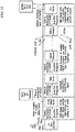
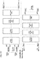
- FIG. 1 is a schematic illustrating a first example configuration of a satellite transceiver 100.
- Multi-Tbps data aggregate and disaggregation module 100 includes mux/demux logic to send data transmissions as laser communications beams 120 or as MMW communications 130 to and from ground stations and endpoint devices.
- the different MMW bands are illustrated by the N RF branches which radiate using a common reflector owing to size weight and power constraints associated with the satellite.
- the MMW bands are aggregated passively post power amplification; an example technique for accomplishing this is described in U.S. Patent Application Publication No. 2017/0317741 A1 , titled "Wireless Communication Utilizing Post-Amplification Carrier Aggregation" and filed 27 April 2016.
- a multi-band co-axial feed structure can also be used to passively aggregate the different MMW bands.
- the data carrying capacity in each MMW band is limited by the amount of RF bandwidth available and the maximum spectral efficiency possible in each band.
- several such bands will need to be multiplexed along with free space optical transmissions.
- free space optical transmission uses a separate aperture and its own transmission chain.
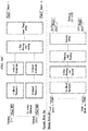
- FIG. 2 is a schematic illustrating a first example system configuration of a satellite transceiver and a plurality of ground stations according to particular embodiments described herein.
- FIG. 1 illustrates an example of a hybrid optical uplink and Q/V+E bands or E+W bands for downlink.
- An optical ground station may be located at each of four different sites and equipped with modulated uplink laser beams to the satellite. A distance d between any two sites may be configured to be greater than a maximum reuse distance for the beam.
- the sites may be located at atmospherically-independent weather cells (e.g., for station diversity).
- FIG. 3 is a schematic illustrating a second example system configuration of a satellite transceiver and a plurality of ground stations according to particular embodiments described herein.
- FIG. 2 illustrates an example of a combined Q/V- and E-band at the satellite and at the ground station for the example of achieving 0.5 Tbps capacity bi-directionally with GEO satellites.
- Tx denotes a transmitter
- Rx denotes a receiver.
- the transceiver may comprise two 3 m Tx antennae (one Q/V-band, and one E-band) and two 2.5 m Tx antennae (one Q/V-band, and one E-band), wherein the beams are dual-polarized.
- the ground stations may each comprise one E-band Tx/Tx 12 m antenna and one V-band Tx/Rx 12 m antenna, wherein the beams are dual-polarized. In particular embodiments, seven ground stations may be required to achieve an overall bandwidth of 0.5 Tbps.
- K a -band uplink in the 27.5-30 GHz range e.g., 2.5 GHz available spectrum
- K a -band downlink in the 17.7-18.6 GHz, and 18.8-20.2 GHz e.g., 2.3 GHz available spectrum
- Q/V-band uplink in the 42.5-47, 47.2-50.2, 50.4-51.4 GHz range e.g., > 5 GHz available spectrum
- Q/V downlink in the 37.5-42.5 GHz range e.g., 5 GHz available spectrum
- E-band uplink in the 81-86 GHz e.g., 5 GHz available spectrum
- E-band downlink at 71-76 GHz e.g., 5 GHz available spectrum.
- the number of simultaneous beams for 0.5 Tbps capacity in each direction may be fifteen beams for K a - and Q/V-bands, or seven beams for an E- or Q/V and E band combination.
- particular embodiments may need eighteen beams for K a - and Q/V-bands, and nine beams for combined E-and Q/V- and E-bands ( see Fig. 2 and 3 ), based on assumptions of a 2.5-meter airborne antenna diameter and a 3-meter ground station diameter at any of the communications frequencies.
- FIG. 4 is a schematic illustrating a third example system configuration of a space vehicle (comprising the satellite communications payload) and a plurality of ground stations according to particular embodiments described herein.
- FIG. 3 illustrates multiple-site SISO at individual frequencies (K a , V, or E). Such embodiments may be based on particular assumptions to achieve 0.5 Tbps capacity in each direction in links with space vehicle, such as, by way of example and not limitation: space vehicle includes one three-meter transmit antenna (at K a , V, or E), one 2.5-meter receive antenna (K a , V, E), and dual-polarized beams; ground station includes: one twelve-meter transmit and receive antenna, and dual-polarized beams.
- the number of sites to achieve 0.5 Tbps at E- or Q/V-band may be fifteen.
- FIG. 5 is a schematic illustrating a fourth example system configuration of a satellite transceiver and a plurality of ground stations according to particular embodiments described herein.
- Particular embodiments provide multiple-site SISO at combined Q/V and E-bands.
- Particular embodiments may be based on particular assumptions to achieve 0.5 Tbps capacity in each direction in links with GEO satellites, such as, by way of example and not limitation: spacecraft-side includes two 3-meter transmit antennas (e.g., one Q/V-band, one E-band), two 2.5-meter receive antennas (e.g., one Q/V-band, one E-band), and dual-polarized beams; ground station includes: one 12-meter transmit and receive antenna Q/V-band antenna, one 12-meter E-band antenna, and dual-polarized beams.
- the number of sites to achieve 0.5 Tbps at E- or Q/V-band may be cut to about half (to 7 sites) relative to use of other communications bands by themselves.
- FIG. 6 is a schematic illustrating a fifth example system configuration of a space vehicle and a plurality of ground stations according to particular embodiments described herein.
- Particular embodiments provide a multiple-site 2X2 MIMO architecture: to achieve 0.5 Tbps bi-directionally in links with space vehicles, particular embodiments may be based on assumptions, such as, by way of example and not limitation: four 2-meter antennas on the space vehicle, 6-meter spacing between transmitter and receiver antennas, and dual-polarized beam.
- the ground station may include: two 12-meter antennas. Required number of sites is 9.
- FIG. 7 is a schematic illustrating a sixth example system configuration of a space vehicle and a plurality of ground stations according to particular embodiments described herein.
- Particular embodiments provide a multiple-site 3X3 MIMO architecture: to achieve 0.5 Tbps in each direction (GEO range), particular embodiments may be based on assumptions, such as, by way of example and not limitation: six 2-meter antennas on the space vehicle, 6-meter spacing between transmitter and receiver antennas, and dual-polarized beam.
- the ground station may include: three 12-meter antennas. Required number of sites is 6.
- Ka-band uplink in 27.5 to 30 GHz range (2.5 GHz available spectrum), and Ka-band downlink in the 17.7 to 18.6GHz, and 18.8-20.2 GHz (2.3 GHz available spectrum); Q/V-band uplink in the 42.5-47, 47.2-50.2, 50.4-51.4 GHz range (> 5GHz available spectrum), and Q/V downlink in the 37.5 to 42.5 GHz range (5 GHz available spectrum); E-band uplink in the 81 to 86 GHz (5 GHz available spectrum), and E-band downlink at 71 to 76 GHz) 5 GHz available spectrum). Particular embodiments may support different values in these communications bands.
- Particular embodiments provide targeting system-wide capacity of 0.5 Tbps. Assuming that all sites can operate at high (e.g., 99%) link availability, and that the sites are sufficiently distant from each other such that there is negligible inter-site correlation between probabilities of rain, link analysis may indicate the number of required sites for different frequencies of SISO communications and system availability.
- 41 beams may be required for K a -band communications, 15 beams may be required for Q/V-band and E-band communications, and 7 beams may be required for links that use a combination Q/V and E bands.
- the transmit aperture diameter may be 3 meters and the receiver aperture diameter may be 2.5 meters.
- Targeting 99.99% system availability at this capacity may require 45 beams at K a -band, 18 beams for Q/V- or E-band, and only 9 beams for Q/V- and E-band combination.
- the 3 additional beams (needed for availability) may be in hot standby: ready to pick up some load when one or more beams go down due to weather. Power consumption for these beams is reduced primarily due to solid-state-amplifiers being used in a low duty cycle and digital electronics where consumption is based on data throughput FPGA demodulator/decoder, and I/Q modulator and digital to analog converter. Very low data rate signals may continue to be sent to the 3 back-up sites to ensure rapid switchover to full data rate is possible.
- the combined Q/V- and E-band configuration may use 9 dual-polarized beams on each band and only 9 versus 18 ground stations.
- Table 1 summarizes the minimum required number of RF/MMW sites. Table 1. The minimum required number of RF/MMW for different system availability assumptions. Required number of sites (99% site availability assumed) K a -Band Q/V Band E-Band Q/V + E Combined Capacity ⁇ 0.5 Tbps (GEO range) 41 15 15 7 99% system availability 43 16 16 8 99.9% system availability 44 17 17 9 99.99% system availability 45 18 18 9 Assumptions Satellite transmit aperture (m) 3 3 3 3 Satellite receive aperture (m) 2.5 2.5 2.5 2.5 2.5 2.5 2.5 2.5 2.5 2.5
- Table 2 shows examples values for mass, power, and normalized cost for all three options, along with the parameters that may significantly impact the terminal cost.
- SSPAs solid-state power amplifiers
- the combined dual-band embodiment reduces the number of unique ground stations from 18 to 9.
- a boom may be required.
- CAPEX capital expenditures
- OPEX operating expenses
- MIMO Multiple-Input Multiple-Output
- the combined Q/V and E-band system may be applied here to further increase the satellite communications capacity.
- MIMO builds on the basic SISO architecture using the same receiver and transmitter chain. However, the required numbers of chains may differ.
- Each transmitter has the capability to send a unique dual-polarized stream to multiple locations (for availability), with one site being used at a time ( Figs. 4 and 5 ).
- the 2x2 and 3x3 architectures each send 2 or 3 such sets of streams to the active site where the receiver provides the signal processing to separate out the streams using a spatial tie equalizer ( Fig. 6 ).
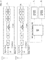
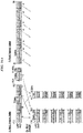
- FIG. 8 is a schematic illustrating an example configuration of a satellite feeder link receiver for providing SISO transmissions.
- the signals received on the various feeds go through an ortho-mode transducer to split them into Left Hand Circularly Polarized (LHCP) and Right Hand Circularly Polarized (RHCP) signals which are then downconverted to a common Intermediate frequency.
- LHCP Left Hand Circularly Polarized
- RHCP Right Hand Circularly Polarized
- the various intermediate frequency signals are downconverted using an I/Q receiver.
- the analog I/Q signals are sampled at Nyquist rate and sent to the payload after buffering and packet switching.
- FIG. 9 is a schematic illustrating an example configuration of a space-vehicle feeder link transmitter for providing SISO transmissions.
- FIG. 9 shows several data streams that are upconverted through an I/Q mixer structure to a common Intermediate frequency.
- the IF signals in different branches are upconverted to a variety of different MMW bands, which are then amplified using travelling waveguide tube amplifiers and radiated using a common dish reflector.
- FIG. 10 is a schematic illustrating an example frequency reference system for providing SISO transmissions.
- individual bands may use either the Q/V- or E-band system, and a combination of bands may use both systems.
- the figure shows direct digital synthesis chips to generate the two LOs required in a typical super-heterodyne architecture.
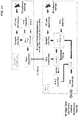
- FIG. 11 is a schematic illustrating an example configuration of a ground station.
- This example identifies: the need for fiberoptic access at the ground station (SISO/MIMO/Optical Ground Station Access); the need fpr a high-speed edge router to effectively manage data movement - for example requiring fast hardware pluse, for example, 100GbE interfaces; Data Server and switch infrastructure for data management beyond just passing packets; Optical Transport hardware providing wavelength conversion and wavelength multiplexing over long-haul; Core Router with larger backbone to handle maximum data-rate to/from centralized location and data handoff to ISPs; and Vendor access to connect high-rates to the Internet.
- FIG. 12 is a schematic illustrating signal processing according to particular embodiments described herein.
- MIMO builds on the basic SISO architecture using the same receiver and transmitter chain. However, the required numbers of chains may differ.
- Each transmitter has the capability to send a unique dual-polarized stream to multiple locations (for availability), with one site being used at a time.
- N sets of streams e.g., 2x2 and 3x3 architectures each send 2 or 3 such sets of streams
- STE Spatial Time Equalizer
- FIG. 13 is a schematic illustrating a 2x2 MIMO architecture for dual polarization.
- the figure shows the least mean squares ("LMS") algorithm implementing the STE along with some additional detail for one of the eight weights.
- LMS least mean squares
- Each complex weight has a number of taps in the transversal filter based on time-bandwidth product and multipath. Note that the antenna may also contribute to internal multipath since the space vehicle body may contribute large reflections into the side lobes of the antennae.
- MIMO requires fewer sites for both 2x2 and 3x3 compared to SISO to achieve both the minimum required capacity and availability.
- the apertures have slightly reduced size, but must be configured in a uniform linear array. This may require booms with joints to reposition from the stowed configuration.
- the 2x2 requires a total of four 2-meter antennas while the 3x3 requires six 2-meter antennas.
- Each simultaneous channel may require 2 x N receive and transmit chains where N is the MIMO dimension.
- Table 3 Space Time Equalizer Complexity 2X2 MIMO 3x3 MIMO Bands ⁇ Q/V E Q/V E Number of simultaneous beams of capacity 9 9 6 6 Number of beams for availability 12 12 8 8 HPA power before back-off 6.2 7.2 5.2 6.1 Back-off (dB) 2.1 2.1 2.1 2.1 2.1 Transmit aperture size 2 2 2 2 2 2 Receive aperture size 2 2 2 2 2
- Mass and power for all four options are summarized in Table 4 along with parameters that most drive the terminal cost. For all cases, dual redundant SSPAs are used.
- the 3x3 MIMO reduces the number of ground sites to eight at the cost of a more complex space vehicle.
- the MIMO mass is noticeably higher than similar SISO cases as booms have been assumed necessary to position the antennas and clear the SV service link antennas. Table 4 .
- per site capacity may be 70% higher than SISO.
- V- and E-bands may need nine sites to achieve 500Gbps (for capacity).
- the number of simultaneous beams for capacity may be nine for either Q/V or E-bands assuming high (e.g., 99.99%) system availability.
- the number of beams required for high link availability may be twelve beams.
- 3x3 MIMO only six simultaneous beams may be needed for high availability, and only eight simultaneous beams for high availability, again using either Q/V- or E-bands. In either case, use of a 2-meter diameter transmitter apertures and 2-meter diameter receiver apertures is assumed.
- the 2X2 per site capacity may be approximately 70% higher than SISO.
- Q/V- and E-bands require only nine sites to achieve 0.5 Tbps bi-directionally in links with GEO satellite, compared with 23 sites for K a -band.
- flight antenna separation at the satellite may be eight meters for all bands, while antenna separation on the satellite may be eight meters for K a -band, and six meters for Q/V- or E-bands.
- Table 6 summarizes the 3X3 MIMO (3 receive and 3 transmit antennas) antenna requirements and separations for uplink and downlink.
- the 3X3 per site capacity may be approximately 2.5 times greater than SISO.
- V- and E-bands may require only 6 sites to achieve 0.5 Tbps at GEO range, compared with 15 sites for K a -band. Table 6.
- Link availability provides targeting-system-wide MMW capacity of 0.5 Tbps at GEO range. Particular embodiments may be based on an assumption that all sites can operate at high link availability while remaining sufficiently separated and distant so that there is low inter-site correlation between probabilities of rain. Table 5 summarizes the number of sites to achieve different degrees of link availability. Table 7. Number of sites required for achieving 0.5 Tbps bi-directionally n links with GEO satellites, and at different system availabilities. MIMO 2X2 MIMO 3X3 Bands ⁇ V E V E 0.5 Tbps capacity 9 9 6 6 99% system availability 10 10 7 7 99.9% system availability 11 11 8 8 99.99% system availability 12 12 8 8 8 8 8
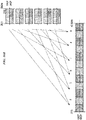
- FIG. 14 is a schematic illustrating an example MIMO ground station with a receiver.
- the ground station MIMO antennas may need to be separated by 8-50 kms. All the sampled signals from the multiple ground antenna sites need to be brought to a central location for MIMO receiver processing.
- sampled baseband signals from remote sites are packetized and sent over a dedicated optical fiber backbone to the main site to be processed along with all the other signals received at the various MIMO antennas.
- the MIMO receiver processing is done at the main site.
- the separated data streams are then sent to the central data distribution facility.
- Table 8 summarizes and compares the quantity and diameter of flight transmitters and receiver antenna diameters as well as the quantity and diameter of ground antennas for the cases of SISO and MIMO, at different communications frequencies. Table 8. Quantity, flight and ground aperture diameters for cases of SISO and MIMO at different frequency bands. Tx denotes transmit and Rx denotes receive. Tx denotes transmitter and Rx denotes receiver.
- Particular embodiments may provide channelization on uplink. Particular embodiments may further provide implementation of cross-polarization interference cancellation or other types of interference cancellation on the satellite. Particular embodiments may further provide oval satellite antennas, which may widen the beam in the direction of spacing of the MIMO ground stations, as well as mitigating pointing error.
- K a dual-polarized • ground stations: V- and E-band (71-76 GHz, 81-86 GHz) dual-polarized uplink; Q-band dual-polarized downlink • spectrum/ground station: 27 GHz forward channel, 6 GHz return channel Table 7. Summary of frequencies for three satellite transceiver designs.
- Example 1 47.2-50.2 & 50.4-51.4 37.5-40.5 * 17.8-18.8 & 19.7-20.2 29.5-30.0
- Example 2 47.2-50.2 & 50.4-51.4, 81-86 37.5-40.5 ** 17.8-18.8 & 19.7-20.2 29.5-30.0
- Example 3 47.2-50.2 & 50.4-51.4, 71-76, 81-86 37.5-40.5 ** 17.8-18.8 & 19.7-20.2 29.5-30.0
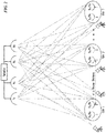
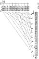
- FIG. 15A illustrates a forward channel frequency plan according to a first example embodiment ("Example 1") of a system configuration described herein.
- the V/K a -Band forward frequency plan illustrated in FIG. 15A may support 12 user beams by each ground station, thereby requiring 30 ground stations per satellite transceiver. As shown, ten of the user beams may be assigned 750MHz and two of the user beams may be assigned 250MHz, thereby requiring five local oscillator (LO) frequencies.
- LO local oscillator
- FIG. 15B illustrates a return channel frequency plan according to the example embodiment of FIG. 15A .
- 12 user beams may be supported by each ground station, and each of the beams assigned to a ground station for the forward channel may be assigned to the same gateway for the return channel.
- all 12 user beams may be assigned 250MHz, thereby requiring six LO frequencies.
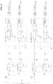
- FIG. 15C is a schematic illustrating forward/return payload block diagram according to the example embodiment of FIG. 15A .
- V-band signals received from the ground stations are processed (e.g., down-converted, then filtered and routed) to generate individual K a user beams to transmit information to end users' devices.
- the K a user beams received from end users' devices are processed (e.g., filtered and routed, then up-converted) to generate Q-band signals to transmit information back to the ground stations.
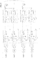
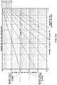
- FIG. 16A illustrates a forward channel frequency plan according to a second example embodiment ("Example 2") of a system configuration described herein.
- the V-Band + E-Band (at 81-86 GHz) forward frequency plan illustrated in FIG. 16A may provide 10GHz of additional forward uplink bandwidth for each gateway.
- This example configuration may support 24 user beams by each ground station, thereby requiring only 15 ground stations per satellite transceiver. In this example configuration, any user beams previously assigned 250MHz may be assigned 750MHz, thereby requiring 12 LO frequencies.
- FIG. 16B illustrates a return channel frequency plan according to the example embodiment of FIG. 16A .
- 24 user beams may be supported by each ground station, and each of the beams assigned to a ground station for the forward channel may be assigned to the same gateway for the return channel.
- all 24 user beams may be assigned 250 MHz (providing a 3:1 forward to return bandwidth ratio), requiring six LO frequencies.
- both polarizations may be used for the return transmission.
- no additional return traveling-wave tube amplifiers (TWTAs) may be required (as compared to Example 1).
- FIG. 16C is a schematic illustrating forward/return payload block diagram according to the example embodiment of FIG. 16A .
- V-band and E-band signals received from the ground stations are processed (e.g., separately down-converted, then jointly filtered and routed) to generate individual K a user beams to transmit information to end users' devices.
- the K a user beams received from end users' devices are processed (e.g., filtered and routed, then up-converted) to generate Q-band signals to transmit information back to the ground stations
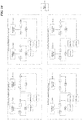
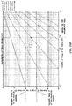
- FIG. 17A illustrates a forward channel frequency plan according to a third example embodiment ("Example 3") of a system configuration described herein.
- the V-Band + E-Band (in the 71-76 GHz and 81-86 GHz bandwidths) forward frequency plan illustrated in FIG. 16A may provide 20GHz of additional forward uplink bandwidth for each gateway (relative to Example 1).
- This example configuration may support 36 user beams by each ground station, thereby requiring only 10 ground stations per satellite transceiver.
- all user beams may be assigned 750MHz, thereby requiring 18 LO frequencies (the forward bandwidth assignments for each beam may be comparable to Example 2).
- FIG. 17B illustrates a return channel frequency plan according to the example embodiment of FIG. 17A .
- 36 user beams may be supported by each ground station, and each of the beams assigned to a ground station for the forward channel may be assigned to the same gateway for the return channel.
- all 36 user beams may be assigned 166 MHz (providing a 4.5:1 forward to return bandwidth ratio), requiring nine LO frequencies (as compared to six LO frequencies for Examples 1 and 2).
- both polarizations may be used for the return transmission.
- no additional return traveling-wave tube amplifiers TWTAs
- TWTAs return traveling-wave tube amplifiers
- Example 2 (relative to Example 1), the additional forward uplink bandwidth for Example 2 may reduce the number of ground stations by 50%.
- the additional mass and DC power required for the E-band components may be offset by a reduction of V-band units required.
- the slight increase in mass for Example 2 accounts for the additional LOs for the E-band frequency translation.
- Example 3 (relative to Example 1), the significant reduction in mass and power is attributable to the reduction in the number of required ground stations. Table 8 . Comparison of mass and power requirements.
- particular embodiments may use a N+P gateway redundancy approach to determine the minimum number of gateways required such that at least X of them are simultaneously available 99.9 percent of the time (overall 99.9 percent gateway link availability), where X is the number of ground stations in a given system configuration.
- X is 30 for Example 1, 15 for Example 2, and 10 for Example 3.
- Particular embodiments may use a binomial distribution for N + P, where N is ⁇ 30, 15, 10 ⁇ gateways, and P is in the range of 1-5 extra gateways. Based on the following assumptions:
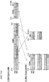
- FIG. 18A is a chart illustrating results of calculating a recommended number of diversity gateways for the example embodiment described with respect to Example 1 (forward channel: V-band uplink/K a -band downlink; return channel: K a uplink/Q-band downlink), based on varying the number of diversity gateways provisioned for the system configuration with 30 ground stations (12 user beams/gateway).
- FIG. 18A is a chart illustrating results of calculating a recommended number of diversity gateways for the example embodiment described with respect to Example 1 (forward channel: V-band uplink/K a -band downlink; return channel: K a uplink/Q-band downlink), based on varying the number of diversity gateways provisioned for the system configuration with 30 ground stations (12 user beams/gateway).
- FIG. 18A is a chart illustrating results of calculating a recommended number of diversity gateways for the example embodiment described with respect to Example 1 (forward channel: V-band uplink/K a -band downlink; return channel: K a up
- 18B is a chart illustrating results of calculating a recommended number of diversity gateways for the example embodiment described with respect to Example 2 (forward channel: V-band+E-band [81-86 GHz] uplink/K a -band downlink; return channel: K a uplink/Q-band downlink), based on varying the number of diversity gateways provisioned for the system configuration with 15 ground stations (24 user beams/gateway).
- FIG. 18B is a chart illustrating results of calculating a recommended number of diversity gateways for the example embodiment described with respect to Example 2 (forward channel: V-band+E-band [81-86 GHz] uplink/K a -band downlink; return channel: K a uplink/Q-band downlink), based on varying the number of diversity gateways provisioned for the system configuration with 15 ground stations (24 user beams/gateway).
- 18C is a chart illustrating results of calculating a recommended number of diversity gateways for the example embodiment described with respect to Example 3 (forward channel: V-band+E-band [71-76 GHz and 81-86 GHz] uplink/K a -band downlink; return channel: K a uplink/Q-band downlink), based on varying the number of diversity gateways provisioned for the system configuration with 10 ground stations (36 user beams/gateway). In all three instances, Pis assumed to be 2%, corresponding to 98% availability for each individual gateway.
- Example 1 Example 2
- Example 3 Primary Ground Stations 30 15 10 Diversity Gateways 2 2 2
- ground station may be used interchangeably with the term "gateway.”
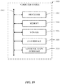
- FIG. 19 illustrates an example computer system 1900.
- one or more computer systems 1900 perform one or more steps of one or more methods described or illustrated herein.
- one or more computer systems 1900 provide functionality described or illustrated herein.
- software running on one or more computer systems 1900 performs one or more steps of one or more methods described or illustrated herein or provides functionality described or illustrated herein.
- Particular embodiments include one or more portions of one or more computer systems 1900.
- reference to a computer system may encompass a computing device, and vice versa, where appropriate.
- reference to a computer system may encompass one or more computer systems, where appropriate.
- computer system 1900 may be an embedded computer system, a system-on-chip (SOC), a single-board computer system (SBC) (such as, for example, a computer-on-module (COM) or system-on-module (SOM)), a desktop computer system, a laptop or notebook computer system, an interactive kiosk, a mainframe, a mesh of computer systems, a mobile telephone, a personal digital assistant (PDA), a server, a tablet computer system, an augmented/virtual reality device, or a combination of two or more of these.
- SOC system-on-chip
- SBC single-board computer system
- COM computer-on-module
- SOM system-on-module
- computer system 1900 may include one or more computer systems 1900; be unitary or distributed; span multiple locations; span multiple machines; span multiple data centers; or reside in a cloud, which may include one or more cloud components in one or more networks.
- one or more computer systems 1900 may perform without substantial spatial or temporal limitation one or more steps of one or more methods described or illustrated herein.
- one or more computer systems 1900 may perform in real time or in batch mode one or more steps of one or more methods described or illustrated herein.
- One or more computer systems 1900 may perform at different times or at different locations one or more steps of one or more methods described or illustrated herein, where appropriate.
- computer system 1900 includes a processor 1902, memory 1904, storage 1906, an input/output (I/O) interface 1908, a communication interface 1910, and a bus 1912.
- I/O input/output
- this disclosure describes and illustrates a particular computer system having a particular number of particular components in a particular arrangement, this disclosure contemplates any suitable computer system having any suitable number of any suitable components in any suitable arrangement.
- processor 1902 includes hardware for executing instructions, such as those making up a computer program.
- processor 1902 may retrieve (or fetch) the instructions from an internal register, an internal cache, memory 1904, or storage 1906; decode and execute them; and then write one or more results to an internal register, an internal cache, memory 1904, or storage 1906.
- processor 1902 may include one or more internal caches for data, instructions, or addresses. This disclosure contemplates processor 1902 including any suitable number of any suitable internal caches, where appropriate.
- processor 1902 may include one or more instruction caches, one or more data caches, and one or more translation lookaside buffers (TLBs).
- TLBs translation lookaside buffers
- Instructions in the instruction caches may be copies of instructions in memory 1904 or storage 1906, and the instruction caches may speed up retrieval of those instructions by processor 1902.
- Data in the data caches may be copies of data in memory 1904 or storage 1906 for instructions executing at processor 1902 to operate on; the results of previous instructions executed at processor 1902 for access by subsequent instructions executing at processor 1902 or for writing to memory 1904 or storage 1906; or other suitable data.
- the data caches may speed up read or write operations by processor 1902.
- the TLBs may speed up virtual-address translation for processor 1902.
- processor 1902 may include one or more internal registers for data, instructions, or addresses. This disclosure contemplates processor 1902 including any suitable number of any suitable internal registers, where appropriate. Where appropriate, processor 1902 may include one or more arithmetic logic units (ALUs); be a multi-core processor; or include one or more processors 1902. Although this disclosure describes and illustrates a particular processor, this disclosure contemplates any suitable processor.
- ALUs arith
- memory 1904 includes main memory for storing instructions for processor 1902 to execute or data for processor 1902 to operate on.
- computer system 1900 may load instructions from storage 1906 or another source (such as, for example, another computer system 1900) to memory 1904.
- Processor 1902 may then load the instructions from memory 1904 to an internal register or internal cache.
- processor 1902 may retrieve the instructions from the internal register or internal cache and decode them.
- processor 1902 may write one or more results (which may be intermediate or final results) to the internal register or internal cache.
- Processor 1902 may then write one or more of those results to memory 1904.
- processor 1902 executes only instructions in one or more internal registers or internal caches or in memory 1904 (as opposed to storage 1906 or elsewhere) and operates only on data in one or more internal registers or internal caches or in memory 1904 (as opposed to storage 1906 or elsewhere).
- One or more memory buses (which may each include an address bus and a data bus) may couple processor 1902 to memory 1904.
- Bus 1912 may include one or more memory buses, as described below.
- one or more memory management units reside between processor 1902 and memory 1904 and facilitate accesses to memory 1904 requested by processor 1902.
- memory 1904 includes random access memory (RAM). This RAM may be volatile memory, where appropriate.
- this RAM may be dynamic RAM (DRAM) or static RAM (SRAM). Moreover, where appropriate, this RAM may be single-ported or multi-ported RAM.
- Memory 1904 may include one or more memories 1904, where appropriate. Although this disclosure describes and illustrates particular memory, this disclosure contemplates any suitable memory.
- storage 1906 includes mass storage for data or instructions.
- storage 1906 may include a hard disk drive (HDD), a floppy disk drive, flash memory, an optical disc, a magneto-optical disc, magnetic tape, or a Universal Serial Bus (USB) drive or a combination of two or more of these.
- Storage 1906 may include removable or non-removable (or fixed) media, where appropriate.
- Storage 1906 may be internal or external to computer system 1900, where appropriate.
- storage 1906 is non-volatile, solid-state memory.
- storage 1906 includes read-only memory (ROM).
- this ROM may be mask-programmed ROM, programmable ROM (PROM), erasable PROM (EPROM), electrically erasable PROM (EEPROM), electrically alterable ROM (EAROM), or flash memory or a combination of two or more of these.
- This disclosure contemplates mass storage 1906 taking any suitable physical form.
- Storage 1906 may include one or more storage control units facilitating communication between processor 1902 and storage 1906, where appropriate.
- storage 1906 may include one or more storages 1906.
- I/O interface 1908 includes hardware, software, or both, providing one or more interfaces for communication between computer system 1900 and one or more I/O devices.
- Computer system 1900 may include one or more of these I/O devices, where appropriate.
- One or more of these I/O devices may enable communication between a person and computer system 1900.
- an I/O device may include a keyboard, keypad, microphone, monitor, mouse, printer, scanner, speaker, still camera, stylus, tablet, touch screen, trackball, video camera, another suitable I/O device or a combination of two or more of these.
- An I/O device may include one or more sensors. This disclosure contemplates any suitable I/O devices and any suitable I/O interfaces 1908 for them.
- I/O interface 1908 may include one or more device or software drivers enabling processor 1902 to drive one or more of these I/O devices.
- I/O interface 1908 may include one or more I/O interfaces 1908, where appropriate.
- communication interface 1910 includes hardware, software, or both providing one or more interfaces for communication (such as, for example, packet-based communication) between computer system 1900 and one or more other computer systems 1900 or one or more networks.
- communication interface 1910 may include a network interface controller (NIC) or network adapter for communicating with an Ethernet or other wire-based network or a wireless NIC (WNIC) or wireless adapter for communicating with a wireless network, such as a WI-FI network.
- NIC network interface controller
- WNIC wireless NIC
- WI-FI network wireless network
- computer system 1900 may communicate with an ad hoc network, a personal area network (PAN), a local area network (LAN), a wide area network (WAN), a metropolitan area network (MAN), or one or more portions of the Internet or a combination of two or more of these.
- PAN personal area network
- LAN local area network
- WAN wide area network
- MAN metropolitan area network
- computer system 1900 may communicate with a wireless PAN (WPAN) (such as, for example, a BLUETOOTH WPAN), a WI-FI network, a WI-MAX network, a cellular telephone network (such as, for example, a Global System for Mobile Communications (GSM) network), or other suitable wireless network or a combination of two or more of these.
- WPAN wireless PAN
- WI-FI wireless personal area network
- WI-MAX wireless personal area network
- WI-MAX wireless personal area network
- cellular telephone network such as, for example, a Global System for Mobile Communications (GSM) network
- GSM Global System
- bus 1912 includes hardware, software, or both coupling components of computer system 1200 to each other.
- bus 1912 may include an Accelerated Graphics Port (AGP) or other graphics bus, an Enhanced Industry Standard Architecture (EISA) bus, a front-side bus (FSB), a HYPER-TRANSPORT (HT) interconnect, an Industry Standard Architecture (ISA) bus, an INFINI-BAND interconnect, a low-pin-count (LPC) bus, a memory bus, a Micro Channel Architecture (MCA) bus, a Peripheral Component Interconnect (PCI) bus, a PCI-Express (PCIe) bus, a serial advanced technology attachment (SATA) bus, a Video Electronics Standards Association local (VLB) bus, or another suitable bus or a combination of two or more of these.
- Bus 1912 may include one or more buses 1912, where appropriate.
- a computer-readable non-transitory storage medium or media may include one or more semiconductor-based or other integrated circuits (ICs) (such, as for example, field-programmable gate arrays (FPGAs) or application-specific ICs (ASICs)), hard disk drives (HDDs), hybrid hard drives (HHDs), optical discs, optical disc drives (ODDs), magneto-optical discs, magneto-optical drives, floppy diskettes, floppy disk drives (FDDs), magnetic tapes, solid-state drives (SSDs), RAM-drives, SECURE DIGITAL cards or drives, any other suitable computer-readable non-transitory storage media, or any suitable combination of two or more of these, where appropriate.
- ICs such, as for example, field-programmable gate arrays (FPGAs) or application-specific ICs (ASICs)
- HDDs hard disk drives
- HHDs hybrid hard drives
- ODDs optical disc drives
- magneto-optical discs magneto-optical drives
- references in the appended claims to an apparatus or system or a component of an apparatus or system being adapted to, arranged to, capable of, configured to, enabled to, operable to, or operative to perform a particular function encompasses that apparatus, system, component, whether or not it or that particular function is activated, turned on, or unlocked, as long as that apparatus, system, or component is so adapted, arranged, capable, configured, enabled, operable, or operative. Additionally, although this disclosure describes or illustrates particular embodiments as providing particular advantages, particular embodiments may provide none, some, or all of these advantages.
Landscapes
- Engineering & Computer Science (AREA)
- Computer Networks & Wireless Communication (AREA)
- Signal Processing (AREA)
- Physics & Mathematics (AREA)
- Astronomy & Astrophysics (AREA)
- Aviation & Aerospace Engineering (AREA)
- General Physics & Mathematics (AREA)
- Electromagnetism (AREA)
- Radio Relay Systems (AREA)
- Mobile Radio Communication Systems (AREA)
Claims (15)
- Emetteur-récepteur comprenant:une pluralité de récepteurs de canal aller, au moins l'un des récepteurs de canal aller recevant (1) un faisceau de communication laser de canal aller émis depuis une station au sol et (2) une fréquence de bande E présentant une bande passante de 81-86 GHz;une pluralité d'émetteurs de canal aller présentant différentes fréquences, les émetteurs de canal aller émettant des faisceaux d'utilisateur vers des dispositifs de point d'extrémité, les faisceaux d'utilisateur étant calculés à partir des faisceaux de communication laser de canal aller et MMW;une pluralité de récepteurs de canal retour, les récepteurs de canal retour recevant des faisceaux d'utilisateur provenant des dispositifs de point d'extrémité;au moins un émetteur de canal retour, l'émetteur de canal retour émettant un faisceau de communication laser de canal retour vers une station au sol, le faisceau de communication laser de canal retour subissant une double polarisation;dans lequel l'émetteur-récepteur est situé sur un système en orbite géosynchrone.
- Emetteur-récepteur selon la revendication 1, comprenant en outre un ou plusieurs processeurs et une mémoire couplée aux processeurs comprenant des instructions aptes à être exécutées par les processeurs, les processeurs étant fonctionnels, lors de l'exécution des instructions, pour:recevoir des données de canal aller émises par un ou plusieurs faisceaux de liaison montante reçus au niveau des récepteurs de canal aller;sur la base des données de canal aller, générer une pluralité de signaux de liaison descendante de canal aller, chacun des signaux de liaison descendante de canal aller comprenant au moins une partie des données de canal aller; etpour chacun des signaux de liaison descendante de canal aller, émettre le signal de liaison descendante de canal aller à l'un des émetteurs de canal aller.
- Emetteur-récepteur selon la revendication 2, les processeurs étant en outre fonctionnels, lors de l'exécution des instructions, pour:recevoir des données de canal retour émises par un ou plusieurs faisceaux de liaison montante reçus au niveau des récepteurs de canal retour;sur la base des données de canal retour, générer un unique signal de liaison descendante de canal retour comprenant les données de canal retour; etémettre le signal de liaison descendante de canal retour à l'émetteur-récepteur de canal retour.
- Emetteur-récepteur selon l'une quelconque des revendications 1 à 3, dans lequel un dispositif de point d'extrémité comprend un dispositif client d'utilisateur final, et dans lequel les faisceaux d'utilisateur sont des signaux RF empiétant sur des faisceaux de communication laser et/ou dans lequel un dispositif de point d'extrémité comprend un dispositif de passerelle de réseau, et dans lequel les faisceaux d'utilisateur émis par les émetteurs de canal aller sont des faisceaux de communication laser émis en plus du signal de fréquence de bande E présentant une bande passante de 71-76 GHz.
- Emetteur-récepteur selon l'une quelconque des revendications 1 à 4, dans lequel le faisceau de communication laser de canal retour est émis en plus d'un signal de fréquence de bande Q plus bande E.
- Emetteur-récepteur selon l'une quelconque des revendications 1 à 5, dans lequel l'émetteur-récepteur est situé sur un satellite en orbite terrestre basse ou en orbite terrestre moyenne.
- Emetteur-récepteur selon l'une quelconque des revendications 1 à 6, dans lequel une alimentation d'antenne unique reçoit des signaux comprenant de multiples types de bandes MMW simultanémentet/oudans lequel chacun des émetteurs de canal aller émet des signaux à l'aide de fréquences sur la bande Q/V, la bande V, la bande W+E ou la bande W.
- Système comprenant un émetteur-récepteur selon l'une quelconque des revendications 1 à 7, un ou plusieurs processeurs et une mémoire couplée aux processeurs comprenant des instructions aptes à être exécutées par les processeurs, les processeurs étant fonctionnels, lors de l'exécution des instructions, pour:recevoir des données de canal aller émises par un ou plusieurs faisceaux de liaison montante reçus au niveau d'une pluralité de récepteurs de canal aller connectés de façon communicative au système, dans lequel au moins l'un des récepteurs de canal aller reçoit (1) un faisceau de communication laser de canal aller émis depuis une station au sol et (2) une fréquence de bande E présentant une bande passante de 81-86 GHz;sur la base des données de canal aller, générer une pluralité de signaux de liaison descendante de canal aller, chacun des signaux de liaison descendante de canal aller comprenant au moins une partie des données de canal aller; etpour chacun des signaux de liaison descendante de canal aller, émettre le signal de liaison descendante de canal aller à l'un d'une pluralité d'émetteurs de canal aller connectés de façon communicative au système, dans lequel les émetteurs de canal aller émettent, à l'aide de différentes fréquences, des faisceaux d'utilisateur à des dispositifs de point d'extrémité, dans lequel les faisceaux d'utilisateur sont calculés à partir des faisceaux de communication laser de canal aller et MMW.
- Système selon la revendication 8, les processeurs étant en outre fonctionnels, lors de l'exécution des instructions, pour:recevoir des données de canal aller émises par un ou plusieurs faisceaux de liaison montante reçus au niveau des récepteurs de canal aller;sur la base des données de canal aller, générer une pluralité de signaux de liaison descendante de canal aller, chacun des signaux de liaison descendante de canal aller comprenant au moins une partie des données de canal aller; etpour chacun des signaux de liaison descendante de canal aller, émettre le signal de liaison descendante de canal aller à l'un des émetteurs de canal aller.
- Système selon la revendication 9, les processeurs étant en outre fonctionnels, lors de l'exécution des instructions, pour:recevoir des données de canal retour émises par un ou plusieurs faisceaux de liaison montante reçus au niveau d'une pluralité de récepteurs de canal retour, dans lequel les récepteurs de canal retour reçoivent des faisceaux d'utilisateur en provenance des dispositifs de point d'extrémité;sur la base des données de canal retour, générer un unique signal de liaison descendante de canal retour comprenant les données de canal retour; etémettre le signal de liaison descendante de canal retour à un émetteur de canal retour, dans lequel l'émetteur de canal retour émet un faisceau de communication laser de canal retour vers une station au sol.
- Système selon l'une quelconque des revendications 8 à 10, dans lequel un dispositif de point d'extrémité comprend un dispositif client d'utilisateur final, et dans lequel les faisceaux d'utilisateur sont des signaux RF empiétant sur des faisceaux de communication laser et/ou dans lequel un dispositif de point d'extrémité comprend un dispositif de passerelle de réseau, et dans lequel les faisceaux d'utilisateur émis par les émetteurs de canal aller sont des faisceaux de communication laser émis en plus d'un signal de fréquence de bande E présentant une bande passante de 71-76 GHz.
- Système selon l'une quelconque des revendications 8 à 11, dans lequel le faisceau de communication laser de canal retour est émis en plus d'un signal de fréquence de bande Q plus bande E et/ou dans lequel le faisceau de communication laser de canal retour subit une double polarisation.
- Système selon l'une quelconque des revendications 8 à 12, dans lequel un ou l'émetteur-récepteur, en particulier un émetteur-récepteur selon l'une quelconque des revendications 1 à 7, est situé sur un satellite en orbite terrestre basse ou en orbite terrestre moyenne.
- Système selon l'une quelconque des revendications 8 à 13, dans lequel une alimentation d'antenne unique reçoit des signaux comprenant de multiples types de bandes MMW simultanément.
- Procédé d'émission de signaux par un émetteur-récepteur en orbite géosynchrone, en particulier par un émetteur-récepteur selon l'une quelconque des revendications 1 à 7, comprenant:par une pluralité de récepteurs de canal aller, recevoir des données de canal aller émises par un ou plusieurs faisceaux de liaison montante, dans lequel au moins l'un des récepteurs de canal aller reçoit (1) un faisceau de communication laser de canal aller émis depuis une station au sol et (2) une fréquence de bande E présentant une bande passante de 81-86 GHz;par un ou plusieurs processeurs de l'émetteur-récepteur et sur la base des données de canal aller, générer une pluralité de signaux de liaison descendante de canal aller, chacun des signaux de liaison descendante de canal aller comprenant au moins une partie des données de canal aller;par une pluralité d'émetteurs-récepteurs de canal aller présentant différentes fréquences, pour chacun des signaux de liaison descendante de canal aller, émettre un ou plusieurs faisceaux d'utilisateur vers un ou plusieurs dispositifs de point d'extrémité, dans lequel les faisceaux d'utilisateur sont calculés à partir des faisceaux de communication laser de canal aller et MMW;par une pluralité de récepteurs de canal retour, recevoir des données de canal retour émises par un ou plusieurs faisceaux de liaison montante reçus au niveau des récepteurs de canal retour, dans lequel les récepteurs de canal retour reçoivent des faisceaux d'utilisateur en provenance des dispositifs de point d'extrémité;par le ou les processeurs de l'émetteur-récepteur et sur la base des données de canal retour, générer un unique signal de liaison descendante de canal retour comprenant les données de canal retour; etpar au moins un émetteur de canal retour, émettre le signal de liaison descendante de canal retour vers une station au sol.
Priority Applications (1)
| Application Number | Priority Date | Filing Date | Title |
|---|---|---|---|
| EP19192056.0A EP3591860B1 (fr) | 2016-12-29 | 2017-12-29 | Communications bidirectionnelles par satellite |
Applications Claiming Priority (2)
| Application Number | Priority Date | Filing Date | Title |
|---|---|---|---|
| US201662440238P | 2016-12-29 | 2016-12-29 | |
| US15/857,605 US10374696B2 (en) | 2016-12-29 | 2017-12-28 | Bidirectional satellite communications |
Related Child Applications (1)
| Application Number | Title | Priority Date | Filing Date |
|---|---|---|---|
| EP19192056.0A Division EP3591860B1 (fr) | 2016-12-29 | 2017-12-29 | Communications bidirectionnelles par satellite |
Publications (2)
| Publication Number | Publication Date |
|---|---|
| EP3343802A1 EP3343802A1 (fr) | 2018-07-04 |
| EP3343802B1 true EP3343802B1 (fr) | 2019-08-28 |
Family
ID=60856966
Family Applications (2)
| Application Number | Title | Priority Date | Filing Date |
|---|---|---|---|
| EP17211123.9A Active EP3343802B1 (fr) | 2016-12-29 | 2017-12-29 | Communications bidirectionnelles par satellite ayant un pinceau d'antenne montant laser et un pinceau montant en ondes millimétriques dans la bande de fréquences e de largeur de bande 81-86 mhz. |
| EP19192056.0A Active EP3591860B1 (fr) | 2016-12-29 | 2017-12-29 | Communications bidirectionnelles par satellite |
Family Applications After (1)
| Application Number | Title | Priority Date | Filing Date |
|---|---|---|---|
| EP19192056.0A Active EP3591860B1 (fr) | 2016-12-29 | 2017-12-29 | Communications bidirectionnelles par satellite |
Country Status (4)
| Country | Link |
|---|---|
| US (2) | US10374696B2 (fr) |
| EP (2) | EP3343802B1 (fr) |
| CN (2) | CN110366830B (fr) |
| WO (1) | WO2018126113A1 (fr) |
Families Citing this family (10)
| Publication number | Priority date | Publication date | Assignee | Title |
|---|---|---|---|---|
| EP3484067B1 (fr) * | 2017-11-13 | 2021-01-27 | NEOSAT GmbH | Procédé de fonctionnement d'un système de communication |
| US10797795B2 (en) * | 2018-11-27 | 2020-10-06 | Facebook, Inc. | System and method of satellite communication |
| US11543645B1 (en) | 2020-03-19 | 2023-01-03 | Meta Platforms, Inc. | Optical beam expander with partial monolithic structure |
| US11689283B1 (en) | 2020-03-30 | 2023-06-27 | Meta Platforms, Inc. | Free-space optical communication system using a backchannel for power optimization |
| US11265076B2 (en) * | 2020-04-10 | 2022-03-01 | Totum Labs, Inc. | System and method for forward error correcting across multiple satellites |
| US11546062B1 (en) | 2020-04-22 | 2023-01-03 | Meta Platforms, Inc. | Wavelength-selectable free-space optical communication |
| CN111641418A (zh) * | 2020-05-07 | 2020-09-08 | 中国电子科技集团公司电子科学研究院 | 一种基于e波段的无线通信系统及其信号处理方法 |
| CN113794503B (zh) * | 2021-09-03 | 2023-08-08 | 上海卫星工程研究所 | 环绕器多频段多通道组合深空中继转发系统 |
| CN115022404B (zh) * | 2022-08-09 | 2022-11-01 | 北京融为科技有限公司 | 一种缓存控制方法和设备 |
| CN116073893B (zh) * | 2023-04-06 | 2023-07-18 | 西安空间无线电技术研究所 | 标定多频段毫米波信号大气传输特性的载荷系统及方法 |
Family Cites Families (22)
| Publication number | Priority date | Publication date | Assignee | Title |
|---|---|---|---|---|
| US6240124B1 (en) * | 1995-06-06 | 2001-05-29 | Globalstar L.P. | Closed loop power control for low earth orbit satellite communications system |
| WO2000014902A2 (fr) | 1998-09-08 | 2000-03-16 | Angel Technologies Corporation | Reseau permettant d'assurer des communications sans fil au moyen d'une plate-forme atmospherique |
| US6873644B1 (en) * | 1999-10-08 | 2005-03-29 | Terence W. Barrett | High data rate inter-satellite communications links method |
| US7680516B2 (en) * | 2001-05-02 | 2010-03-16 | Trex Enterprises Corp. | Mobile millimeter wave communication link |
| US20020176139A1 (en) * | 2001-05-02 | 2002-11-28 | Louis Slaughter | SONET capable millimeter wave communication system |
| US20040001720A1 (en) * | 2002-06-27 | 2004-01-01 | Krill Jerry A. | Satellite-based mobile communication system |
| US20050090198A1 (en) | 2003-10-27 | 2005-04-28 | Christopher Paul F. | Method to extend millimeter wave satellite communication (75-98 GHz) and 3-10 micron laser links to wide areas in the temperate zone |
| EP1844558B1 (fr) | 2005-01-05 | 2018-02-14 | ATC Technologies, LLC | Formation de faisceau adaptatif avec détection multi-utilisateur et réduction de brouillage dans des systèmes et des procédés de communication satellitaire |
| CN101588200B (zh) * | 2006-09-26 | 2013-08-21 | 维尔塞特公司 | 改进的点波束卫星系统 |
| US20090298423A1 (en) * | 2006-10-03 | 2009-12-03 | Viasat, Inc. | Piggy-Back Satellite Payload |
| US20080173533A1 (en) * | 2007-01-22 | 2008-07-24 | John Carlton Mankins | Process and method of making space-solar fuels and other chemicals |
| US20090289839A1 (en) | 2007-09-26 | 2009-11-26 | Viasat, Inc | Dynamic Sub-Channel Sizing |
| JP2011501618A (ja) * | 2007-10-25 | 2011-01-06 | バッテル メモリアル インスティテュート | 光−ミリメートル波変換 |
| US8942562B2 (en) * | 2011-05-31 | 2015-01-27 | A Optix Technologies, Inc. | Integrated commercial communications network using radio frequency and free space optical data communication |
| US8913894B2 (en) | 2012-07-13 | 2014-12-16 | Raytheon Company | High-bandwidth optical communications relay architecture |
| FR2997255B1 (fr) | 2012-10-18 | 2014-12-26 | Thales Sa | Systeme de telecommunication par satellite permettant d'assurer un trafic en etoile et un trafic maille |
| US20150029932A1 (en) | 2013-07-18 | 2015-01-29 | David A. Slemp | Ultra broadband networks and methods |
| US10181895B2 (en) | 2014-09-04 | 2019-01-15 | Honeywell International Inc. | Free space laser and millimetre wave(MMW) network for airborne relay networks |
| US9967792B2 (en) | 2015-03-16 | 2018-05-08 | Space Systems/Loral, Llc | Communication system with multi band gateway |
| CN105553539B (zh) * | 2015-12-16 | 2019-01-18 | 天津大学 | 一种卫星间太赫兹通信系统构架及其信息传输方法 |
| US10158419B2 (en) | 2016-04-27 | 2018-12-18 | Facebook, Inc. | Wireless communication utilizing post-amplification carrier aggregation |
| US20180013193A1 (en) * | 2016-07-06 | 2018-01-11 | Google Inc. | Channel reconfigurable millimeter-wave radio frequency system by frequency-agile transceivers and dual antenna apertures |
-
2017
- 2017-12-28 US US15/857,605 patent/US10374696B2/en active Active
- 2017-12-29 EP EP17211123.9A patent/EP3343802B1/fr active Active
- 2017-12-29 CN CN201780087678.XA patent/CN110366830B/zh active Active
- 2017-12-29 WO PCT/US2017/068898 patent/WO2018126113A1/fr active Application Filing
- 2017-12-29 CN CN202210533837.7A patent/CN114978284A/zh active Pending
- 2017-12-29 EP EP19192056.0A patent/EP3591860B1/fr active Active
-
2019
- 2019-05-21 US US16/418,303 patent/US10594389B2/en active Active
Non-Patent Citations (1)
| Title |
|---|
| None * |
Also Published As
| Publication number | Publication date |
|---|---|
| WO2018126113A1 (fr) | 2018-07-05 |
| US20190363783A1 (en) | 2019-11-28 |
| US10374696B2 (en) | 2019-08-06 |
| EP3591860B1 (fr) | 2021-03-17 |
| EP3591860A1 (fr) | 2020-01-08 |
| CN114978284A (zh) | 2022-08-30 |
| US20180191428A1 (en) | 2018-07-05 |
| CN110366830A (zh) | 2019-10-22 |
| EP3343802A1 (fr) | 2018-07-04 |
| US10594389B2 (en) | 2020-03-17 |
| CN110366830B (zh) | 2022-05-24 |
Similar Documents
| Publication | Publication Date | Title |
|---|---|---|
| EP3343802B1 (fr) | Communications bidirectionnelles par satellite ayant un pinceau d'antenne montant laser et un pinceau montant en ondes millimétriques dans la bande de fréquences e de largeur de bande 81-86 mhz. | |
| US8660482B2 (en) | Broadband satellite with dual frequency conversion and bandwidth aggregation | |
| CN102273096B (zh) | 天基局域网(sblan) | |
| US7024158B2 (en) | Broadband communication satellite | |
| EP2168257B1 (fr) | Systèmes et procédés de communications mobiles par satellite | |
| US20180205448A1 (en) | Distributed satcom aperture on fishing boat | |
| US11201707B2 (en) | Secured independent hosted payload operations | |
| Devaraj et al. | Planet high speed radio: Crossing Gbps from a 3U cubesat | |
| Inigo et al. | Review of terabit/s satellite, the next generation of HTS systems | |
| US20170237182A1 (en) | Antenna with beamwidth reconfigurable circularly polarized radiators | |
| US11515935B2 (en) | Satellite MIMO system | |
| JP2001308770A (ja) | 最小の遅延の静止衛星通信システム | |
| US9648568B2 (en) | Hybrid dual-band satellite communication system | |
| US6825815B1 (en) | Steerable uplink antenna for moveable redundant beams | |
| Narytnik et al. | Coverage aarea formation for a low-orbit broadband access system with distributed satellites | |
| González et al. | Low cost and compact Ka-band mobile Satcom terminal | |
| Amane et al. | Development of Advanced HTS Onboard Ka-band Antennas for Engineering Test Satellite 9 | |
| Codispoti et al. | The Alphasat TDP# 5 experiment and challenges for future Q/V-band systems exploitation | |
| Munemasa et al. | Advanced demonstration plans of high-speed laser communication | |
| US20240049012A1 (en) | Systems and Methods for Network Performance Monitoring | |
| US20240048470A1 (en) | Network Performance Monitoring Devices | |
| Rao et al. | Design options for a Multi-beam/multi-band Airborne Antenna | |
| Kawai et al. | ETS-VI multibeam satellite communications systems | |
| Dybdal et al. | Wide scanning reflector antennas for satellite crosslinks | |
| Evans | Proposed US multimedia satellites |
Legal Events
| Date | Code | Title | Description |
|---|---|---|---|
| PUAI | Public reference made under article 153(3) epc to a published international application that has entered the european phase |
Free format text: ORIGINAL CODE: 0009012 |
|
| STAA | Information on the status of an ep patent application or granted ep patent |
Free format text: STATUS: THE APPLICATION HAS BEEN PUBLISHED |
|
| AK | Designated contracting states |
Kind code of ref document: A1 Designated state(s): AL AT BE BG CH CY CZ DE DK EE ES FI FR GB GR HR HU IE IS IT LI LT LU LV MC MK MT NL NO PL PT RO RS SE SI SK SM TR |
|
| AX | Request for extension of the european patent |
Extension state: BA ME |
|
| STAA | Information on the status of an ep patent application or granted ep patent |
Free format text: STATUS: REQUEST FOR EXAMINATION WAS MADE |
|
| 17P | Request for examination filed |
Effective date: 20190102 |
|
| RBV | Designated contracting states (corrected) |
Designated state(s): AL AT BE BG CH CY CZ DE DK EE ES FI FR GB GR HR HU IE IS IT LI LT LU LV MC MK MT NL NO PL PT RO RS SE SI SK SM TR |
|
| GRAP | Despatch of communication of intention to grant a patent |
Free format text: ORIGINAL CODE: EPIDOSNIGR1 |
|
| STAA | Information on the status of an ep patent application or granted ep patent |
Free format text: STATUS: GRANT OF PATENT IS INTENDED |
|
| INTG | Intention to grant announced |
Effective date: 20190322 |
|
| GRAS | Grant fee paid |
Free format text: ORIGINAL CODE: EPIDOSNIGR3 |
|
| GRAA | (expected) grant |
Free format text: ORIGINAL CODE: 0009210 |
|
| STAA | Information on the status of an ep patent application or granted ep patent |
Free format text: STATUS: THE PATENT HAS BEEN GRANTED |
|
| AK | Designated contracting states |
Kind code of ref document: B1 Designated state(s): AL AT BE BG CH CY CZ DE DK EE ES FI FR GB GR HR HU IE IS IT LI LT LU LV MC MK MT NL NO PL PT RO RS SE SI SK SM TR |
|
| REG | Reference to a national code |
Ref country code: GB Ref legal event code: FG4D |
|
| REG | Reference to a national code |
Ref country code: CH Ref legal event code: EP |
|
| REG | Reference to a national code |
Ref country code: AT Ref legal event code: REF Ref document number: 1173710 Country of ref document: AT Kind code of ref document: T Effective date: 20190915 |
|
| REG | Reference to a national code |
Ref country code: IE Ref legal event code: FG4D |
|
| REG | Reference to a national code |
Ref country code: DE Ref legal event code: R096 Ref document number: 602017006566 Country of ref document: DE |
|
| REG | Reference to a national code |
Ref country code: NL Ref legal event code: MP Effective date: 20190828 |
|
| REG | Reference to a national code |
Ref country code: LT Ref legal event code: MG4D |
|
| PG25 | Lapsed in a contracting state [announced via postgrant information from national office to epo] |
Ref country code: FI Free format text: LAPSE BECAUSE OF FAILURE TO SUBMIT A TRANSLATION OF THE DESCRIPTION OR TO PAY THE FEE WITHIN THE PRESCRIBED TIME-LIMIT Effective date: 20190828 Ref country code: PT Free format text: LAPSE BECAUSE OF FAILURE TO SUBMIT A TRANSLATION OF THE DESCRIPTION OR TO PAY THE FEE WITHIN THE PRESCRIBED TIME-LIMIT Effective date: 20191230 Ref country code: NO Free format text: LAPSE BECAUSE OF FAILURE TO SUBMIT A TRANSLATION OF THE DESCRIPTION OR TO PAY THE FEE WITHIN THE PRESCRIBED TIME-LIMIT Effective date: 20191128 Ref country code: NL Free format text: LAPSE BECAUSE OF FAILURE TO SUBMIT A TRANSLATION OF THE DESCRIPTION OR TO PAY THE FEE WITHIN THE PRESCRIBED TIME-LIMIT Effective date: 20190828 Ref country code: BG Free format text: LAPSE BECAUSE OF FAILURE TO SUBMIT A TRANSLATION OF THE DESCRIPTION OR TO PAY THE FEE WITHIN THE PRESCRIBED TIME-LIMIT Effective date: 20191128 Ref country code: SE Free format text: LAPSE BECAUSE OF FAILURE TO SUBMIT A TRANSLATION OF THE DESCRIPTION OR TO PAY THE FEE WITHIN THE PRESCRIBED TIME-LIMIT Effective date: 20190828 Ref country code: LT Free format text: LAPSE BECAUSE OF FAILURE TO SUBMIT A TRANSLATION OF THE DESCRIPTION OR TO PAY THE FEE WITHIN THE PRESCRIBED TIME-LIMIT Effective date: 20190828 Ref country code: HR Free format text: LAPSE BECAUSE OF FAILURE TO SUBMIT A TRANSLATION OF THE DESCRIPTION OR TO PAY THE FEE WITHIN THE PRESCRIBED TIME-LIMIT Effective date: 20190828 |
|
| PG25 | Lapsed in a contracting state [announced via postgrant information from national office to epo] |
Ref country code: RS Free format text: LAPSE BECAUSE OF FAILURE TO SUBMIT A TRANSLATION OF THE DESCRIPTION OR TO PAY THE FEE WITHIN THE PRESCRIBED TIME-LIMIT Effective date: 20190828 Ref country code: AL Free format text: LAPSE BECAUSE OF FAILURE TO SUBMIT A TRANSLATION OF THE DESCRIPTION OR TO PAY THE FEE WITHIN THE PRESCRIBED TIME-LIMIT Effective date: 20190828 Ref country code: ES Free format text: LAPSE BECAUSE OF FAILURE TO SUBMIT A TRANSLATION OF THE DESCRIPTION OR TO PAY THE FEE WITHIN THE PRESCRIBED TIME-LIMIT Effective date: 20190828 Ref country code: LV Free format text: LAPSE BECAUSE OF FAILURE TO SUBMIT A TRANSLATION OF THE DESCRIPTION OR TO PAY THE FEE WITHIN THE PRESCRIBED TIME-LIMIT Effective date: 20190828 Ref country code: GR Free format text: LAPSE BECAUSE OF FAILURE TO SUBMIT A TRANSLATION OF THE DESCRIPTION OR TO PAY THE FEE WITHIN THE PRESCRIBED TIME-LIMIT Effective date: 20191129 Ref country code: IS Free format text: LAPSE BECAUSE OF FAILURE TO SUBMIT A TRANSLATION OF THE DESCRIPTION OR TO PAY THE FEE WITHIN THE PRESCRIBED TIME-LIMIT Effective date: 20191228 |
|
| REG | Reference to a national code |
Ref country code: AT Ref legal event code: MK05 Ref document number: 1173710 Country of ref document: AT Kind code of ref document: T Effective date: 20190828 |
|
| PG25 | Lapsed in a contracting state [announced via postgrant information from national office to epo] |
Ref country code: TR Free format text: LAPSE BECAUSE OF FAILURE TO SUBMIT A TRANSLATION OF THE DESCRIPTION OR TO PAY THE FEE WITHIN THE PRESCRIBED TIME-LIMIT Effective date: 20190828 |
|
| PG25 | Lapsed in a contracting state [announced via postgrant information from national office to epo] |
Ref country code: PL Free format text: LAPSE BECAUSE OF FAILURE TO SUBMIT A TRANSLATION OF THE DESCRIPTION OR TO PAY THE FEE WITHIN THE PRESCRIBED TIME-LIMIT Effective date: 20190828 Ref country code: AT Free format text: LAPSE BECAUSE OF FAILURE TO SUBMIT A TRANSLATION OF THE DESCRIPTION OR TO PAY THE FEE WITHIN THE PRESCRIBED TIME-LIMIT Effective date: 20190828 Ref country code: DK Free format text: LAPSE BECAUSE OF FAILURE TO SUBMIT A TRANSLATION OF THE DESCRIPTION OR TO PAY THE FEE WITHIN THE PRESCRIBED TIME-LIMIT Effective date: 20190828 Ref country code: RO Free format text: LAPSE BECAUSE OF FAILURE TO SUBMIT A TRANSLATION OF THE DESCRIPTION OR TO PAY THE FEE WITHIN THE PRESCRIBED TIME-LIMIT Effective date: 20190828 Ref country code: IT Free format text: LAPSE BECAUSE OF FAILURE TO SUBMIT A TRANSLATION OF THE DESCRIPTION OR TO PAY THE FEE WITHIN THE PRESCRIBED TIME-LIMIT Effective date: 20190828 Ref country code: EE Free format text: LAPSE BECAUSE OF FAILURE TO SUBMIT A TRANSLATION OF THE DESCRIPTION OR TO PAY THE FEE WITHIN THE PRESCRIBED TIME-LIMIT Effective date: 20190828 |
|
| PG25 | Lapsed in a contracting state [announced via postgrant information from national office to epo] |
Ref country code: SK Free format text: LAPSE BECAUSE OF FAILURE TO SUBMIT A TRANSLATION OF THE DESCRIPTION OR TO PAY THE FEE WITHIN THE PRESCRIBED TIME-LIMIT Effective date: 20190828 Ref country code: SM Free format text: LAPSE BECAUSE OF FAILURE TO SUBMIT A TRANSLATION OF THE DESCRIPTION OR TO PAY THE FEE WITHIN THE PRESCRIBED TIME-LIMIT Effective date: 20190828 Ref country code: CZ Free format text: LAPSE BECAUSE OF FAILURE TO SUBMIT A TRANSLATION OF THE DESCRIPTION OR TO PAY THE FEE WITHIN THE PRESCRIBED TIME-LIMIT Effective date: 20190828 Ref country code: IS Free format text: LAPSE BECAUSE OF FAILURE TO SUBMIT A TRANSLATION OF THE DESCRIPTION OR TO PAY THE FEE WITHIN THE PRESCRIBED TIME-LIMIT Effective date: 20200224 |
|
| REG | Reference to a national code |
Ref country code: DE Ref legal event code: R097 Ref document number: 602017006566 Country of ref document: DE |
|
| PLBE | No opposition filed within time limit |
Free format text: ORIGINAL CODE: 0009261 |
|
| STAA | Information on the status of an ep patent application or granted ep patent |
Free format text: STATUS: NO OPPOSITION FILED WITHIN TIME LIMIT |
|
| PG2D | Information on lapse in contracting state deleted |
Ref country code: IS |
|
| 26N | No opposition filed |
Effective date: 20200603 |
|
| REG | Reference to a national code |
Ref country code: BE Ref legal event code: MM Effective date: 20191231 |
|
| PG25 | Lapsed in a contracting state [announced via postgrant information from national office to epo] |
Ref country code: MC Free format text: LAPSE BECAUSE OF FAILURE TO SUBMIT A TRANSLATION OF THE DESCRIPTION OR TO PAY THE FEE WITHIN THE PRESCRIBED TIME-LIMIT Effective date: 20190828 Ref country code: SI Free format text: LAPSE BECAUSE OF FAILURE TO SUBMIT A TRANSLATION OF THE DESCRIPTION OR TO PAY THE FEE WITHIN THE PRESCRIBED TIME-LIMIT Effective date: 20190828 |
|
| PG25 | Lapsed in a contracting state [announced via postgrant information from national office to epo] |
Ref country code: LU Free format text: LAPSE BECAUSE OF NON-PAYMENT OF DUE FEES Effective date: 20191229 Ref country code: IE Free format text: LAPSE BECAUSE OF NON-PAYMENT OF DUE FEES Effective date: 20191229 Ref country code: FR Free format text: LAPSE BECAUSE OF NON-PAYMENT OF DUE FEES Effective date: 20191231 |
|
| PG25 | Lapsed in a contracting state [announced via postgrant information from national office to epo] |
Ref country code: BE Free format text: LAPSE BECAUSE OF NON-PAYMENT OF DUE FEES Effective date: 20191231 |
|
| PG25 | Lapsed in a contracting state [announced via postgrant information from national office to epo] |
Ref country code: CY Free format text: LAPSE BECAUSE OF FAILURE TO SUBMIT A TRANSLATION OF THE DESCRIPTION OR TO PAY THE FEE WITHIN THE PRESCRIBED TIME-LIMIT Effective date: 20190828 |
|
| PG25 | Lapsed in a contracting state [announced via postgrant information from national office to epo] |
Ref country code: HU Free format text: LAPSE BECAUSE OF FAILURE TO SUBMIT A TRANSLATION OF THE DESCRIPTION OR TO PAY THE FEE WITHIN THE PRESCRIBED TIME-LIMIT; INVALID AB INITIO Effective date: 20171229 Ref country code: MT Free format text: LAPSE BECAUSE OF FAILURE TO SUBMIT A TRANSLATION OF THE DESCRIPTION OR TO PAY THE FEE WITHIN THE PRESCRIBED TIME-LIMIT Effective date: 20190828 |
|
| REG | Reference to a national code |
Ref country code: CH Ref legal event code: PL |
|
| PG25 | Lapsed in a contracting state [announced via postgrant information from national office to epo] |
Ref country code: LI Free format text: LAPSE BECAUSE OF NON-PAYMENT OF DUE FEES Effective date: 20201231 Ref country code: CH Free format text: LAPSE BECAUSE OF NON-PAYMENT OF DUE FEES Effective date: 20201231 |
|
| REG | Reference to a national code |
Ref country code: DE Ref legal event code: R081 Ref document number: 602017006566 Country of ref document: DE Owner name: META PLATFORMS, INC., US Free format text: FORMER OWNER: FACEBOOK, INC., MENLO PARK, CALIF., US |
|
| PG25 | Lapsed in a contracting state [announced via postgrant information from national office to epo] |
Ref country code: MK Free format text: LAPSE BECAUSE OF FAILURE TO SUBMIT A TRANSLATION OF THE DESCRIPTION OR TO PAY THE FEE WITHIN THE PRESCRIBED TIME-LIMIT Effective date: 20190828 |
|
| P01 | Opt-out of the competence of the unified patent court (upc) registered |
Effective date: 20230524 |
|
| PGFP | Annual fee paid to national office [announced via postgrant information from national office to epo] |
Ref country code: GB Payment date: 20231229 Year of fee payment: 7 |
|
| PGFP | Annual fee paid to national office [announced via postgrant information from national office to epo] |
Ref country code: DE Payment date: 20231222 Year of fee payment: 7 |