EP3343752B1 - Method and system for correcting initial zero offset - Google Patents
Method and system for correcting initial zero offset Download PDFInfo
- Publication number
- EP3343752B1 EP3343752B1 EP16853029.3A EP16853029A EP3343752B1 EP 3343752 B1 EP3343752 B1 EP 3343752B1 EP 16853029 A EP16853029 A EP 16853029A EP 3343752 B1 EP3343752 B1 EP 3343752B1
- Authority
- EP
- European Patent Office
- Prior art keywords
- permanent magnet
- synchronous motor
- magnet synchronous
- resolver
- counter electromotive
- Prior art date
- Legal status (The legal status is an assumption and is not a legal conclusion. Google has not performed a legal analysis and makes no representation as to the accuracy of the status listed.)
- Active
Links
Images


Classifications
-
- H—ELECTRICITY
- H02—GENERATION; CONVERSION OR DISTRIBUTION OF ELECTRIC POWER
- H02P—CONTROL OR REGULATION OF ELECTRIC MOTORS, ELECTRIC GENERATORS OR DYNAMO-ELECTRIC CONVERTERS; CONTROLLING TRANSFORMERS, REACTORS OR CHOKE COILS
- H02P21/00—Arrangements or methods for the control of electric machines by vector control, e.g. by control of field orientation
- H02P21/24—Vector control not involving the use of rotor position or rotor speed sensors
- H02P21/32—Determining the initial rotor position
-
- H—ELECTRICITY
- H02—GENERATION; CONVERSION OR DISTRIBUTION OF ELECTRIC POWER
- H02P—CONTROL OR REGULATION OF ELECTRIC MOTORS, ELECTRIC GENERATORS OR DYNAMO-ELECTRIC CONVERTERS; CONTROLLING TRANSFORMERS, REACTORS OR CHOKE COILS
- H02P21/00—Arrangements or methods for the control of electric machines by vector control, e.g. by control of field orientation
- H02P21/14—Estimation or adaptation of machine parameters, e.g. flux, current or voltage
- H02P21/18—Estimation of position or speed
-
- H—ELECTRICITY
- H02—GENERATION; CONVERSION OR DISTRIBUTION OF ELECTRIC POWER
- H02P—CONTROL OR REGULATION OF ELECTRIC MOTORS, ELECTRIC GENERATORS OR DYNAMO-ELECTRIC CONVERTERS; CONTROLLING TRANSFORMERS, REACTORS OR CHOKE COILS
- H02P6/00—Arrangements for controlling synchronous motors or other dynamo-electric motors using electronic commutation dependent on the rotor position; Electronic commutators therefor
- H02P6/08—Arrangements for controlling the speed or torque of a single motor
-
- H—ELECTRICITY
- H02—GENERATION; CONVERSION OR DISTRIBUTION OF ELECTRIC POWER
- H02P—CONTROL OR REGULATION OF ELECTRIC MOTORS, ELECTRIC GENERATORS OR DYNAMO-ELECTRIC CONVERTERS; CONTROLLING TRANSFORMERS, REACTORS OR CHOKE COILS
- H02P6/00—Arrangements for controlling synchronous motors or other dynamo-electric motors using electronic commutation dependent on the rotor position; Electronic commutators therefor
- H02P6/14—Electronic commutators
- H02P6/16—Circuit arrangements for detecting position
-
- H—ELECTRICITY
- H02—GENERATION; CONVERSION OR DISTRIBUTION OF ELECTRIC POWER
- H02P—CONTROL OR REGULATION OF ELECTRIC MOTORS, ELECTRIC GENERATORS OR DYNAMO-ELECTRIC CONVERTERS; CONTROLLING TRANSFORMERS, REACTORS OR CHOKE COILS
- H02P6/00—Arrangements for controlling synchronous motors or other dynamo-electric motors using electronic commutation dependent on the rotor position; Electronic commutators therefor
- H02P6/14—Electronic commutators
- H02P6/16—Circuit arrangements for detecting position
- H02P6/18—Circuit arrangements for detecting position without separate position detecting elements
-
- H—ELECTRICITY
- H02—GENERATION; CONVERSION OR DISTRIBUTION OF ELECTRIC POWER
- H02P—CONTROL OR REGULATION OF ELECTRIC MOTORS, ELECTRIC GENERATORS OR DYNAMO-ELECTRIC CONVERTERS; CONTROLLING TRANSFORMERS, REACTORS OR CHOKE COILS
- H02P6/00—Arrangements for controlling synchronous motors or other dynamo-electric motors using electronic commutation dependent on the rotor position; Electronic commutators therefor
- H02P6/14—Electronic commutators
- H02P6/16—Circuit arrangements for detecting position
- H02P6/18—Circuit arrangements for detecting position without separate position detecting elements
- H02P6/182—Circuit arrangements for detecting position without separate position detecting elements using back-emf in windings
-
- H—ELECTRICITY
- H02—GENERATION; CONVERSION OR DISTRIBUTION OF ELECTRIC POWER
- H02P—CONTROL OR REGULATION OF ELECTRIC MOTORS, ELECTRIC GENERATORS OR DYNAMO-ELECTRIC CONVERTERS; CONTROLLING TRANSFORMERS, REACTORS OR CHOKE COILS
- H02P2203/00—Indexing scheme relating to controlling arrangements characterised by the means for detecting the position of the rotor
- H02P2203/03—Determination of the rotor position, e.g. initial rotor position, during standstill or low speed operation
-
- H—ELECTRICITY
- H02—GENERATION; CONVERSION OR DISTRIBUTION OF ELECTRIC POWER
- H02P—CONTROL OR REGULATION OF ELECTRIC MOTORS, ELECTRIC GENERATORS OR DYNAMO-ELECTRIC CONVERTERS; CONTROLLING TRANSFORMERS, REACTORS OR CHOKE COILS
- H02P2207/00—Indexing scheme relating to controlling arrangements characterised by the type of motor
- H02P2207/05—Synchronous machines, e.g. with permanent magnets or DC excitation
Definitions
- the present disclosure relates to the technical field of a permanent magnet synchronous motor and a resolver, and in particular to a method and a system for correcting an initial zero position deviation.
- a resolver In order to achieve a high-performance speed regulation of a permanent magnet synchronous motor, a resolver is required to accurately detect the position of a rotor of the permanent magnet synchronous motor.
- the accuracy of the detected position of the rotor of the permanent magnet synchronous motor is important for the performance of a motor control system, a fail of which may even cause an unstable operation of the motor speed regulation system.
- it is required to ensure that an initial zero position of the motor is consistent with an initial zero position of the resolver, which is however difficult due to many factors.
- FIG. 1 The electrical principle of a brushless resolver is shown in Figure 1 .
- a primary excitation winding (R1-R2) of the resolver and orthogonal secondary induction windings (S1-S3, S2-S4) of the resolver are all located on a stator side.
- no winding is arranged on the rotor of the variable reluctance resolver. Because of the special design of the rotor, a secondary coupling varies sinusoidally as an angle position varies.
- inductive potentials are generated in the two secondary output windings, with values of a product of a sine value of a rotation angle of the rotor and the excitation and a product of a cosine value of the rotation angle of the rotor and the excitation. Therefore, a rotor angle can be measured with the resolver.
- Figure 2 is a schematic diagram of an initial positioning of a permanent magnet synchronous motor according to a conventional technology.
- a direction of a resultant magnetic field is an axis direction of phase A, i.e., a direction vertical to a horizontal line (defined as a zero position of the motor).
- a constant stator magnetic field and a magnetic field of a permanent magnet rotor may attract the rotor to a same position, that is, the rotor of the motor is driven to and locked at the zero position of the motor, thereby correcting a deviation between the zero position of the resolver and the zero position of the motor.
- a friction resistance and a cogging torque always exist in the permanent magnet synchronous motor even if the motor is in an unloaded state. Therefore, in the initial positioning of the resolver, the rotor of the motor cannot be completely driven to and locked at the axis direction of phase A (i.e., the zero position of the motor), and thus an error angle ⁇ ⁇ exists in an initial orientation of the magnetic field of the rotor of the motor.
- US 2004/061461 A1 discloses an apparatus for controlling a permanent-magnet rotary machine.
- a motor controller performs a dq vector control process to control the permanent-magnet rotary machine in a dq coordinate system which has a d-axis representing the direction of a magnetic field of the rotor and a q-axis representing a direction perpendicular to the d-axis.
- a magnetic pole position correcting quantity ⁇ ofs is determined to correct a magnetic pole position ⁇ act detected by a magnetic pole position detector so that a d-axis voltage command value Vdc determined by the dq vector control process will be substantially zero.
- the motor controller controls the phases of armature voltages Vuc, Vvc, Vwc with magnetic pole positions corrected by the magnetic pole position correcting quantity ⁇ ofs . Irrespective of whether the rotary machine is a cylindrical machine or a salient-pole machine, the detected values of magnetic pole positions are appropriately corrected according to a simple process without the need for a voltage detector for thereby efficiently controlling operation of the permanent-magnet rotary machine.
- CN 102545761A discloses an automatic calibrating device for initial zero-position angle of a permanent magnet synchronous motor.
- the device comprises an isolation voltage sensor, a rotating transformer, a voltage sample decoder, a rotating transformer decoding chip, and a signal processor, wherein the isolation voltage sensor is connected with the voltage sample decoder, and the rotating transformer is connected with the rotating transformer decoding chip.
- the processing process of the signal processor comprises the steps of initializing; sampling a position and a line voltage; judging the current angle; acquiring the line voltage; judging; and calibrating.
- CN 204465405U discloses an apparatus for zeroing and calibrating an initial angle of a rotor of a permanent magnet synchronous motor (PMSM).
- the apparatus comprises a driving unit, a rotary transformer, and a zeroing and calibrating module.
- the driving unit is used for outputting specific driving current to a stator winding.
- the rotary transformer is used for outputting a corresponding measuring result signal according to the position of the rotor of the PMSM.
- the zeroing and calibrating module is used for acquiring the rotor angle information of the PMSM based on the measuring result signal so as to zero and calibrate the rotor angle of the PMSM according to the rotor angle information.
- An objective of the present disclosure is to provide a method for correcting an initial zero position deviation, to correct an initial zero position deviation between a permanent magnet synchronous motor and a resolver.
- a method for correcting an initial zero position deviation is provided according to the present disclosure.
- the method is applied to a permanent magnet synchronous motor and a resolver.
- the method includes:
- the method includes: driving the rotor of the permanent magnet synchronous motor via a driver.
- the method includes: lighting an indicator lamp when the installation deviation ⁇ ⁇ meets the precision requirement, an indicator lamp is lit.
- the calculating a space vector phase angle ⁇ 1 corresponding to the counter electromotive forces of the stator of the permanent magnet synchronous motor based on the counter electromotive forces includes:
- the position of the resolver is adjusted manually until the installation deviation ⁇ ⁇ meets the precision requirement.
- e q represents the q-axis component obtained by the coordinate transformation
- k represents a constant
- e ab and e bc represent the counter electromotive forces of the stator of the permanent magnet synchronous motor.
- a system for correcting an initial zero position deviation is provided according to the present disclosure.
- the system is applied to a permanent magnet synchronous motor and a resolver.
- the system includes:
- the power device is a driver.
- the system further includes an indicator lamp.
- the indicator lamp is lit by the microprocessor when the installation deviation ⁇ ⁇ meets the precision requirement.
- the regulator is a manual regulator.
- the space vector phase angle ⁇ 1 corresponding to the counter electromotive forces is calculated based on the counter electromotive forces of the stator of the permanent magnet synchronous motor.
- the rotation angle ⁇ 2 measured by the resolver is acquired based on the position of the rotor of the resolver.
- the installation deviation ⁇ ⁇ of the resolver is calculated based on the formula.
- the position of the resolver is adjusted according to a precision requirement.
- the core of the present disclosure is to provide a method and a system for correcting an initial zero position deviation.
- Figure 3 is a flowchart of a method for correcting an initial zero position deviation according to the present disclosure. As shown in Figure 3 , the method for correcting the initial zero position deviation is applied to a permanent magnet synchronous motor and a resolver. The method includes steps S10 to S15.
- step S10 a rotor of the permanent magnet synchronous motor is driven to rotate at a constant speed.
- step S11 counter electromotive forces of a stator of the permanent magnet synchronous motor and an angle of a rotor of the resolver are acquired;
- step S12 a space vector phase angle ⁇ 1 corresponding to the counter electromotive forces of the stator of the permanent magnet synchronous motor is calculated based on the counter electromotive forces.
- step S13 a rotation angle ⁇ 2 measured by the resolver is acquired based on the position of the rotor of the resolver.
- step S14 an installation deviation ⁇ ⁇ corresponding to the space vector phase angle ⁇ 1 and the rotation angle ⁇ 2 is calculated based on a formula.
- step S15 a position of the resolver is adjusted until the installation deviation ⁇ ⁇ meets a precision requirement.
- the formula is ⁇ 2 ⁇ ⁇ 1 ⁇ ⁇ 2 .
- the stator of the permanent magnet synchronous motor may generate three phases of symmetrical counter electromotive forces by cutting a magnetic field, and a sine signal and a cosine signal orthogonal to each other are also generated on the resolver.
- Figure 1 it is assumed that the rotor rotates counterclockwise and a positive direction of each of the counter electromotive forces is set as a direction from a port with a subscript of 1 to a port with a subscript of 2.
- a virtual counter electromotive force space vector rotates counterclockwise and the position thereof coincides with that of the rotor.
- the rotor In a case where one of the three phases of counter electromotive forces reaches a maximum value, the rotor is perpendicular to an axis of this phase. If the phase angle of the counter electromotive force and the angle measured by the resolver at a certain time instant are known, then the installation deviation of the resolver is known.
- the counter electromotive forces of the stator of the permanent magnet synchronous motor and the angle of the rotor of the resolver are acquired firstly.
- the space vector phase angle ⁇ 1 corresponding to the counter electromotive forces of the stator of the permanent magnet synchronous motor is calculated based on the counter electromotive forces.
- the rotation angle ⁇ 2 measured by the resolver is acquired.
- the installation deviation ⁇ ⁇ corresponding to the space vector phase angle ⁇ 1 and the rotation angle ⁇ 2 is calculated based on the formula ⁇ 2 ⁇ ⁇ 1 ⁇ ⁇ 2 .
- Precision requirements on the installation deviation of the resolver are different depending on different scenarios. Therefore, after the installation deviation ⁇ ⁇ of the resolver is acquired, the position of the resolver is adjusted according to the precision requirement until the installation deviation ⁇ ⁇ meets the precision requirement.
- the space vector phase angle ⁇ 1 corresponding to the counter electromotive forces is calculated based on the counter electromotive forces of the stator of the permanent magnet synchronous motor.
- the rotation angle ⁇ 2 measured by the resolver is acquired based on the position of the rotor of the resolver.
- the installation deviation ⁇ ⁇ of the resolver is calculated based on the formula.
- the position of the resolver is adjusted according to a precision requirement.
- step S10 the rotor of the permanent magnet synchronous motor may be driven by a driver.
- an indicator lamp may be lit to promote an operator that the current position meets the precision requirement.
- the operator can be promoted timely that the current position meets the precision requirement, thereby saving the correcting time and improving the efficiency.
- step S12 of calculating the space vector phase angle ⁇ 1 corresponding to the counter electromotive forces of the stator of the permanent magnet synchronous motor based on the counter electromotive forces and the angle of the rotor of the resolver includes:
- Figure 4 is a schematic block diagram of a calculation of a space vector phase angle according to the present disclosure.
- e q represents a q-axis (quadrature axis) component obtained by the coordinate transformation
- k represents a constant generally having a value of 2/3 or 2 / 3
- e ab and e bc represent the counter electromotive forces of the stator of the permanent magnet synchronous motor.
- a d-axis component and the q-axis component are acquired.
- the q-axis component e q is inputted to a PI regulator.
- An estimated electrical angular velocity ⁇ e ⁇ is obtained by acquiring a sum of an output value ⁇ ⁇ e of the PI regulator and an electrical angular velocity ⁇ e of the rotor of the permanent magnet synchronous motor. Then, ⁇ e t + ⁇ 0 is obtained by performing an integration. Finally, the space vector phase angle ⁇ 1 is acquired by a complementation. ⁇ 0 is an initial value.
- the PI regulator in the present disclosure may be a proportional integral regulator.
- Figure 4 shows a discrete control process, the initial value ⁇ 0 may be given arbitrarily.
- step S15 the position of the resolver is adjusted manually until the installation deviation ⁇ ⁇ meets the precision requirement.
- Figure 5 is a structural diagram of a system for correcting an initial zero position deviation according to the present disclosure.
- the system for correcting the initial zero position deviation is applied to a permanent magnet synchronous motor 30 and a resolver 31.
- the system includes a power device 32, a signal acquisition device 33, a microprocessor 34 and a regulator 35.
- the power device 32 is configured to drive a rotor of the permanent magnet synchronous motor 30 to rotate at a constant speed.
- the signal acquisition device 33 is configured to acquire counter electromotive forces of a stator of the permanent magnet synchronous motor and a rotation angle ⁇ 2 measured by the resolver 31.
- the microprocessor 34 is configured to calculate a space vector phase angle ⁇ 1 corresponding to the counter electromotive forces of the stator of the permanent magnet synchronous motor 30 based on the counter electromotive forces, and calculate an installation deviation ⁇ ⁇ corresponding to the space vector phase angle ⁇ 1 and the rotation angle ⁇ 2 based on a formula.
- the regulator 35 is configured to adjust a position of the resolver 31 until the installation deviation ⁇ ⁇ meets a precision requirement.
- the formula is ⁇ 2 ⁇ ⁇ 1 ⁇ ⁇ 2 .
- a precision selection button may be arranged on the microprocessor to select a level of the precision, and the level may be set based on the practical situation.
- the microprocessor calculates the space vector phase angle ⁇ 1 corresponding to the counter electromotive forces of the stator of the permanent magnet synchronous motor based on the counter electromotive forces.
- the rotation angle ⁇ 2 measured by the resolver is acquired based on the position of the rotor of the resolver.
- the installation deviation ⁇ ⁇ of the resolver is calculated based on the formula.
- the position of the resolver is adjusted according to the precision requirement.
- the power device may be a driver.
- the system for correcting the initial zero position deviation may further include an indicator lamp.
- the indicator lamp is lit by the microprocessor.
- the regulator is a manual regulator.
Landscapes
- Engineering & Computer Science (AREA)
- Power Engineering (AREA)
- Control Of Motors That Do Not Use Commutators (AREA)
- Transmission And Conversion Of Sensor Element Output (AREA)
- Control Of Ac Motors In General (AREA)
Description
- The present disclosure relates to the technical field of a permanent magnet synchronous motor and a resolver, and in particular to a method and a system for correcting an initial zero position deviation.
- In order to achieve a high-performance speed regulation of a permanent magnet synchronous motor, a resolver is required to accurately detect the position of a rotor of the permanent magnet synchronous motor. The accuracy of the detected position of the rotor of the permanent magnet synchronous motor is important for the performance of a motor control system, a fail of which may even cause an unstable operation of the motor speed regulation system. For convenient use in practices, in the installation of the resolver, it is required to ensure that an initial zero position of the motor is consistent with an initial zero position of the resolver, which is however difficult due to many factors.
- The electrical principle of a brushless resolver is shown in
Figure 1 . A primary excitation winding (R1-R2) of the resolver and orthogonal secondary induction windings (S1-S3, S2-S4) of the resolver are all located on a stator side. As shown inFigure 1 , no winding is arranged on the rotor of the variable reluctance resolver. Because of the special design of the rotor, a secondary coupling varies sinusoidally as an angle position varies. In a case where the rotor of the resolver rotates with the motor synchronously and an alternating-current excitation voltage is applied to the primary excitation winding, inductive potentials are generated in the two secondary output windings, with values of a product of a sine value of a rotation angle of the rotor and the excitation and a product of a cosine value of the rotation angle of the rotor and the excitation. Therefore, a rotor angle can be measured with the resolver. The input and outputs of the resolver have a relation as:
- When a direct current is applied to a stator winding of the motor, a constant magnetic field is generated on the axis of the winding. Ideally, the constant magnetic field and the magnetic field of the permanent magnet rotor attract the rotor to a same position. In this case, an initial zero position of the permanent magnet rotor can be detected with the above method.
-
Figure 2 is a schematic diagram of an initial positioning of a permanent magnet synchronous motor according to a conventional technology. As shown infigure 2 , in an initial positioning of a resolver, generally, a direct current inflows from phase A (A1-A2), and outflows from phases B (B1-B2) and C (C1-C2). In this case a direction of a resultant magnetic field is an axis direction of phase A, i.e., a direction vertical to a horizontal line (defined as a zero position of the motor). Ideally, a constant stator magnetic field and a magnetic field of a permanent magnet rotor may attract the rotor to a same position, that is, the rotor of the motor is driven to and locked at the zero position of the motor, thereby correcting a deviation between the zero position of the resolver and the zero position of the motor. However, a friction resistance and a cogging torque always exist in the permanent magnet synchronous motor even if the motor is in an unloaded state. Therefore, in the initial positioning of the resolver, the rotor of the motor cannot be completely driven to and locked at the axis direction of phase A (i.e., the zero position of the motor), and thus an error angle Δθ exists in an initial orientation of the magnetic field of the rotor of the motor. -
US 2004/061461 A1 discloses an apparatus for controlling a permanent-magnet rotary machine. During rotation of a rotor of a permanent-magnet rotary machine when an armature current thereof is substantially zero, a motor controller performs a dq vector control process to control the permanent-magnet rotary machine in a dq coordinate system which has a d-axis representing the direction of a magnetic field of the rotor and a q-axis representing a direction perpendicular to the d-axis. A magnetic pole position correcting quantity θofs is determined to correct a magnetic pole position θact detected by a magnetic pole position detector so that a d-axis voltage command value Vdc determined by the dq vector control process will be substantially zero. The motor controller controls the phases of armature voltages Vuc, Vvc, Vwc with magnetic pole positions corrected by the magnetic pole position correcting quantity θofs. Irrespective of whether the rotary machine is a cylindrical machine or a salient-pole machine, the detected values of magnetic pole positions are appropriately corrected according to a simple process without the need for a voltage detector for thereby efficiently controlling operation of the permanent-magnet rotary machine. -
CN 102545761A discloses an automatic calibrating device for initial zero-position angle of a permanent magnet synchronous motor. The device comprises an isolation voltage sensor, a rotating transformer, a voltage sample decoder, a rotating transformer decoding chip, and a signal processor, wherein the isolation voltage sensor is connected with the voltage sample decoder, and the rotating transformer is connected with the rotating transformer decoding chip. It further discloses a method of the automatic calibrating device for the initial zero-position angle of the permanent magnet synchronous motor wherein the processing process of the signal processor comprises the steps of initializing; sampling a position and a line voltage; judging the current angle; acquiring the line voltage; judging; and calibrating. -
CN 204465405U discloses an apparatus for zeroing and calibrating an initial angle of a rotor of a permanent magnet synchronous motor (PMSM). The apparatus comprises a driving unit, a rotary transformer, and a zeroing and calibrating module. The driving unit is used for outputting specific driving current to a stator winding. The rotary transformer is used for outputting a corresponding measuring result signal according to the position of the rotor of the PMSM. The zeroing and calibrating module is used for acquiring the rotor angle information of the PMSM based on the measuring result signal so as to zero and calibrate the rotor angle of the PMSM according to the rotor angle information. - As can be seen, it is desired to solve by those skilled in the art the problem of how to correct the initial zero position deviation between permanent magnet synchronous motor and resolver.
- An objective of the present disclosure is to provide a method for correcting an initial zero position deviation, to correct an initial zero position deviation between a permanent magnet synchronous motor and a resolver.
- In order to solve the above technical problem, a method for correcting an initial zero position deviation is provided according to the present disclosure. The method is applied to a permanent magnet synchronous motor and a resolver. The method includes:
- driving a rotor of the permanent magnet synchronous motor to rotate at a constant speed;
- acquiring counter electromotive forces of a stator of the permanent magnet synchronous motor and a position of a rotor of the resolver;
- calculating a space vector phase angle θ 1 corresponding to the counter electromotive forces of the stator of the permanent magnet synchronous motor based on the counter electromotive forces;
- acquiring, based on the position of the rotor of the resolver, a rotation angle θ 2 measured by the resolver;
- calculating, based on a formula, an installation deviation Δθ corresponding to the space vector phase angle θ 1 and the rotation angle θ 2; and
- manually adjusting a position of the resolver until the installation deviation Δθ meets a precision requirement;
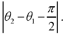
- where the formula is
- Preferably, the method includes: driving the rotor of the permanent magnet synchronous motor via a driver.
- Preferably, the method includes: lighting an indicator lamp when the installation deviation Δθ meets the precision requirement, an indicator lamp is lit.
- Preferably, the calculating a space vector phase angle θ 1 corresponding to the counter electromotive forces of the stator of the permanent magnet synchronous motor based on the counter electromotive forces includes:
- performing a coordinate transformation on the counter electromotive forces of the stator of the permanent magnet synchronous motor;
- inputting a q-axis component obtained by the coordinate transformation to a PI regulator; and
- acquiring a sum of an output value of the PI regulator and an electrical angular velocity of the rotor of the permanent magnet synchronous motor, performing an integration on the sum, and performing a complementation on an integration result to obtain the space vector phase angle θ 1.
- The position of the resolver is adjusted manually until the installation deviation Δθ meets the precision requirement.
- Preferably, the coordinate transformation is performed based on the following formula:

- A system for correcting an initial zero position deviation is provided according to the present disclosure. The system is applied to a permanent magnet synchronous motor and a resolver. The system includes:
- a power device, configured to drive a rotor of the permanent magnet synchronous motor to rotate at a constant speed;
- a signal acquisition device, configured to acquire counter electromotive forces of a stator of the permanent magnet synchronous motor and a rotation angle θ 2 measured by the resolver;
- a microprocessor, configured to calculate a space vector phase angle θ 1 corresponding to the counter electromotive forces of the stator of the permanent magnet synchronous motor based on the counter electromotive forces, and calculate an installation deviation Δθ corresponding to the space vector phase angle θ 1 and the rotation angleθ 2 based on a formula; and
- a regulator, configured to adjust a position of the resolver until the installation deviation Δθ meets a precision requirement;
- where the formula is

- Preferably, the power device is a driver.
- Preferably, the system further includes an indicator lamp.
- The indicator lamp is lit by the microprocessor when the installation deviation Δθ meets the precision requirement.
- The regulator is a manual regulator.
- In the method for correcting the initial zero position deviation according to the present disclosure, the space vector phase angle θ 1 corresponding to the counter electromotive forces is calculated based on the counter electromotive forces of the stator of the permanent magnet synchronous motor. The rotation angle θ 2 measured by the resolver is acquired based on the position of the rotor of the resolver. The installation deviation Δθ of the resolver is calculated based on the formula. Finally, the position of the resolver is adjusted according to a precision requirement. With the method, the initial zero position deviation between the permanent magnet synchronous motor and the resolver can be corrected with simple operations.
-
-
Figure 1 is an electrical schematic diagram of a brushless resolver according to the conventional technology; -
Figure 2 is a schematic diagram of an initial positioning of a permanent magnet synchronous motor according to the conventional technology; -
Figure 3 is a flowchart of a method for correcting an initial zero position deviation according to the present disclosure; -
Figure 4 is a schematic block diagram of a calculation of a space vector phase angle according to the present disclosure; and -
Figure 5 is a structural diagram of a system for correcting an initial zero position deviation according to the present disclosure. - The technical solutions according to the embodiments of the present disclosure will be described below clearly and completely in conjunction with the drawings. Apparently, the described embodiments are only a few rather than all of the embodiments of the present disclosure.
- The core of the present disclosure is to provide a method and a system for correcting an initial zero position deviation.
- In order to make those skilled in the art better understand the technical solutions of the present disclosure, hereinafter, detail description is made in conjunction with the drawings and embodiments.
-
Figure 3 is a flowchart of a method for correcting an initial zero position deviation according to the present disclosure. As shown inFigure 3 , the method for correcting the initial zero position deviation is applied to a permanent magnet synchronous motor and a resolver. The method includes steps S10 to S15. - In step S10, a rotor of the permanent magnet synchronous motor is driven to rotate at a constant speed.
- In step S11, counter electromotive forces of a stator of the permanent magnet synchronous motor and an angle of a rotor of the resolver are acquired;
- In step S12, a space vector phase angle θ 1 corresponding to the counter electromotive forces of the stator of the permanent magnet synchronous motor is calculated based on the counter electromotive forces.
- In step S13, a rotation angle θ 2 measured by the resolver is acquired based on the position of the rotor of the resolver.
- In step S14, an installation deviation Δθ corresponding to the space vector phase angle θ 1 and the rotation angle θ 2 is calculated based on a formula.
- In step S15, a position of the resolver is adjusted until the installation deviation Δθ meets a precision requirement.
- The formula is

- In an implementation, in a case where the rotor of the permanent magnet synchronous motor is driven by an external force to rotate at a certain speed, the stator of the permanent magnet synchronous motor may generate three phases of symmetrical counter electromotive forces by cutting a magnetic field, and a sine signal and a cosine signal orthogonal to each other are also generated on the resolver. As shown in
Figure 1 , it is assumed that the rotor rotates counterclockwise and a positive direction of each of the counter electromotive forces is set as a direction from a port with a subscript of 1 to a port with a subscript of 2. A virtual counter electromotive force space vector rotates counterclockwise and the position thereof coincides with that of the rotor. In a case where one of the three phases of counter electromotive forces reaches a maximum value, the rotor is perpendicular to an axis of this phase. If the phase angle of the counter electromotive force and the angle measured by the resolver at a certain time instant are known, then the installation deviation of the resolver is known. - Therefore, according to the present disclosure, the counter electromotive forces of the stator of the permanent magnet synchronous motor and the angle of the rotor of the resolver are acquired firstly. Next, the space vector phase angle θ 1 corresponding to the counter electromotive forces of the stator of the permanent magnet synchronous motor is calculated based on the counter electromotive forces. Then, the rotation angle θ 2 measured by the resolver is acquired. The installation deviation Δθ corresponding to the space vector phase angle θ 1 and the rotation angle θ 2 is calculated based on the formula

- In the method for correcting the initial zero position deviation according to the present disclosure, the space vector phase angle θ 1 corresponding to the counter electromotive forces is calculated based on the counter electromotive forces of the stator of the permanent magnet synchronous motor. The rotation angle θ 2 measured by the resolver is acquired based on the position of the rotor of the resolver. The installation deviation Δθ of the resolver is calculated based on the formula. Finally, the position of the resolver is adjusted according to a precision requirement. With the method, the initial zero position deviation between the permanent magnet synchronous motor and the resolver can be corrected with simple operations.
- It should be noted that, in a case where a complementation is performed on a first angle of θ 1 and θ 2 which exceeds 2π, 2π is subtracted from the other angle, thereby obtaining the installation deviation

- In step S10, the rotor of the permanent magnet synchronous motor may be driven by a driver.
- Preferably, after step S15, an indicator lamp may be lit to promote an operator that the current position meets the precision requirement.
- By lighting the indicator lamp, the operator can be promoted timely that the current position meets the precision requirement, thereby saving the correcting time and improving the efficiency.
- As a preferred embodiment, step S12 of calculating the space vector phase angle θ 1 corresponding to the counter electromotive forces of the stator of the permanent magnet synchronous motor based on the counter electromotive forces and the angle of the rotor of the resolver includes:
- performing a coordinate transformation on the counter electromotive forces of the stator of the permanent magnet synchronous motor;
- inputting a q-axis component obtained by the coordinate transformation to a PI regulator; and
- acquiring a sum of an output value of the PI regulator and an electrical angular velocity of the rotor of the permanent magnet synchronous motor, performing an integration on the sum, and performing a complementation on an integration result to obtain the space vector phase angle θ 1.
- In order that those skilled in the art better understand the calculation of the space vector phase angle θ 1 according to the present disclosure, reference is made to
Figure 4 , which is a schematic block diagram of a calculation of a space vector phase angle according to the present disclosure. - A coordinate transformation is performed on the counter electromotive forces eab and ebc of the stator of the permanent magnet synchronous motor using the following formula:


- By calculating with the above coordinate transformation formula, a d-axis component and the q-axis component are acquired. The q-axis component eq is inputted to a PI regulator. An estimated electrical angular velocity

- It should be noted that the PI regulator in the present disclosure may be a proportional integral regulator. Besides, since
Figure 4 shows a discrete control process, the initial value θ 0 may be given arbitrarily. - In step S15, the position of the resolver is adjusted manually until the installation deviation Δθ meets the precision requirement.
-
Figure 5 is a structural diagram of a system for correcting an initial zero position deviation according to the present disclosure. The system for correcting the initial zero position deviation is applied to a permanentmagnet synchronous motor 30 and aresolver 31. The system includes apower device 32, asignal acquisition device 33, amicroprocessor 34 and aregulator 35. - The
power device 32 is configured to drive a rotor of the permanentmagnet synchronous motor 30 to rotate at a constant speed. - The
signal acquisition device 33 is configured to acquire counter electromotive forces of a stator of the permanent magnet synchronous motor and a rotation angle θ 2 measured by theresolver 31. - The
microprocessor 34 is configured to calculate a space vector phase angle θ 1 corresponding to the counter electromotive forces of the stator of the permanentmagnet synchronous motor 30 based on the counter electromotive forces, and calculate an installation deviation Δθ corresponding to the space vector phase angle θ 1 and the rotation angleθ 2 based on a formula. - The
regulator 35 is configured to adjust a position of theresolver 31 until the installation deviation Δθ meets a precision requirement. - The formula is

- It should be noted that, for facilitating a check on a precision of the installation, a precision selection button may be arranged on the microprocessor to select a level of the precision, and the level may be set based on the practical situation.
- In the system for correcting the initial zero position deviation, the microprocessor calculates the space vector phase angle θ 1 corresponding to the counter electromotive forces of the stator of the permanent magnet synchronous motor based on the counter electromotive forces. The rotation angle θ 2 measured by the resolver is acquired based on the position of the rotor of the resolver. The installation deviation Δθ of the resolver is calculated based on the formula. Finally, the position of the resolver is adjusted according to the precision requirement. With the system, the initial zero position deviation between the permanent magnet synchronous motor and the resolver can be corrected with simple operations.
- The power device may be a driver.
- The system for correcting the initial zero position deviation may further include an indicator lamp. When the installation deviation Δθ meets the precision requirement, the indicator lamp is lit by the microprocessor.
- The regulator is a manual regulator.
- Since the system according to the second embodiment corresponds to the method according to the first embodiment, one may refer to the first embodiment for details of the system, which is not repeated hereinafter.
- In the above, the method and system for correcting an initial zero position deviation according to the present disclosure are described in detail. Specific examples are described herein to set forth the principle and embodiments of the present disclosure, and the above embodiments are illustrated only for better understanding of the method and the core concept of the present disclosure.
Claims (8)
- A method for correcting an initial zero position deviation, applied to a permanent magnet synchronous motor (30) and a resolver (31), comprising:driving (S10) a rotor of the permanent magnet synchronous motor (30) to rotate at a constant speed;acquiring (S11) counter electromotive forces of a stator of the permanent magnet synchronous motor (30) and a position of a rotor of the resolver (31); calculating (S 12) a space vector phase angle θ 1 corresponding to the counter electromotive forces of the stator of the permanent magnet synchronous motor (30) based on the counter electromotive forces;acquiring (S13), based on the position of the rotor of the resolver (31), a rotation angle θ 2 measured by the resolver (31);calculating (S14), based on a formula, an installation deviation Δθ corresponding to the space vector phase angle θ 1 and the rotation angle θ 2; and manually adjusting (S15) a position of the resolver until the installation deviation Δθ meets a precision requirement;wherein the formula is

- The method for correcting the initial zero position deviation according to claim 1, comprising:
driving (S10) the rotor of the permanent magnet synchronous motor (30) via a driver. - The method for correcting the initial zero position deviation according to claim 1, further comprising:
lighting an indicator lamp when the installation deviation Δθ meets the precision requirement. - The method for correcting the initial zero position deviation according to claim 1, wherein the step (S12) of calculating a space vector phase angle θ 1 corresponding to the counter electromotive forces of the stator of the permanent magnet synchronous motor (30) based on the counter electromotive forces comprises:performing a coordinate transformation on the counter electromotive forces of the stator of the permanent magnet synchronous motor (30);inputting a q-axis component obtained by the coordinate transformation to a PI regulator; andacquiring a sum of an output value of the PI regulator and an electrical angular velocity of the rotor of the permanent magnet synchronous motor (30), performing an integration on the sum, and performing a complementation on an integration result to obtain the space vector phase angle θ 1.
- The method for correcting the initial zero position deviation according to claim 4, wherein the coordinate transformation is performed based on the following formula:

- A system for correcting an initial zero position deviation, applied to a permanent magnet synchronous motor (30) and a resolver (31), comprising:a power device (32), configured to drive a rotor of the permanent magnet synchronous motor (30) to rotate at a constant speed;a signal acquisition device (33), configured to acquire counter electromotive forces of a stator of the permanent magnet synchronous motor (30) and a rotation angle θ 2 measured by the resolver (31);a microprocessor (34), configured to calculate a space vector phase angle θ 1 corresponding to the counter electromotive forces of the stator of the permanent magnet synchronous motor (30) based on the counter electromotive forces, and calculate an installation deviation Δθ corresponding to the space vector phase angle θ 1 and the rotation angle θ 2 based on a formula; anda regulator (35), configured to adjust a position of the resolver (31) until the installation deviation Δθ meets a precision requirement;wherein, the formula is

- The system for correcting the initial zero position deviation according to claim 6, wherein the power device (32) is a driver.
- The system for correcting the initial zero position deviation according to claim 6, further comprising an indicator lamp, wherein the indicator lamp is lit by the microprocessor (34) when the installation deviation Δθ meets the precision requirement.
Applications Claiming Priority (2)
| Application Number | Priority Date | Filing Date | Title |
|---|---|---|---|
| CN201510648687.4A CN105162372B (en) | 2015-10-09 | 2015-10-09 | A kind of method and system of correction initial zero position deviation |
| PCT/CN2016/091008 WO2017059723A1 (en) | 2015-10-09 | 2016-07-22 | Method and system for correcting initial zero offset |
Publications (3)
| Publication Number | Publication Date |
|---|---|
| EP3343752A1 EP3343752A1 (en) | 2018-07-04 |
| EP3343752A4 EP3343752A4 (en) | 2019-05-08 |
| EP3343752B1 true EP3343752B1 (en) | 2023-06-07 |
Family
ID=54803157
Family Applications (1)
| Application Number | Title | Priority Date | Filing Date |
|---|---|---|---|
| EP16853029.3A Active EP3343752B1 (en) | 2015-10-09 | 2016-07-22 | Method and system for correcting initial zero offset |
Country Status (4)
| Country | Link |
|---|---|
| US (1) | US10263556B2 (en) |
| EP (1) | EP3343752B1 (en) |
| CN (1) | CN105162372B (en) |
| WO (1) | WO2017059723A1 (en) |
Families Citing this family (35)
| Publication number | Priority date | Publication date | Assignee | Title |
|---|---|---|---|---|
| CN105162372B (en) * | 2015-10-09 | 2018-08-24 | 中车株洲电力机车研究所有限公司 | A kind of method and system of correction initial zero position deviation |
| DE102016201074B4 (en) * | 2016-01-26 | 2020-07-09 | Baumüller Nürnberg GmbH | Method for detecting a position of a rotating central element of an electric motor |
| CN105656378B (en) * | 2016-03-01 | 2018-07-03 | 广东高标电子科技有限公司 | Counter electromotive force sampling deviation bearing calibration based on counter electromotive force of motor sample circuit |
| CN107404272B (en) * | 2016-05-16 | 2019-08-23 | 广州汽车集团股份有限公司 | Permanent magnet synchronous motor rotation becomes zero-bit initial angle scaling method and calibration system |
| CN106100468A (en) * | 2016-07-08 | 2016-11-09 | 深圳市科陆驱动技术有限公司 | A kind of rotor null adjustment method, device, circuit and rotary transformer |
| CN106533277B (en) * | 2016-12-28 | 2019-04-09 | 北京新能源汽车股份有限公司 | Method and device for checking zero position of rotary transformer of motor |
| CN106849518B (en) * | 2017-02-17 | 2020-06-05 | 深圳市踏路科技有限公司 | Calibration method for hub motor signal detection device |
| CN106849777A (en) * | 2017-03-27 | 2017-06-13 | 苏州汇川联合动力系统有限公司 | A kind of permagnetic synchronous motor rotation becomes Zero correction method and system |
| CN107834934B (en) * | 2017-12-01 | 2020-05-08 | 重庆长安汽车股份有限公司 | Electric automobile and automatic correction method and system for initial position of rotary transformer of electric automobile |
| CN108111080B (en) * | 2017-12-27 | 2019-11-05 | 浙江零跑科技有限公司 | Automatic rotor angle aligning device and method for permanent magnet synchronous motor |
| CN109039176B (en) * | 2018-08-31 | 2019-05-21 | 浙江台运汽车科技有限公司 | A kind of permanent magnet synchronous motor rotation becomes the detection device and detection method of zero-bit initial angle |
| CN109474088B (en) * | 2018-10-31 | 2024-01-12 | 佛山市顺德区金泰德胜电机有限公司 | Method for controlling initial zero offset of permanent magnet motor and rotary transformer |
| CN111200380A (en) * | 2018-11-16 | 2020-05-26 | 郑州宇通客车股份有限公司 | Method and device for detecting initial rotary transformation electrical angle of new energy automobile motor |
| CN111200387B (en) * | 2018-11-16 | 2021-12-21 | 郑州宇通客车股份有限公司 | Method and device for correcting initial electrical angle of motor rotating transformer of new energy automobile |
| CN109861594A (en) * | 2018-12-20 | 2019-06-07 | 无锡华宸控制技术有限公司 | A kind of method and device measuring rotor-position deviation |
| CN111865163B (en) * | 2019-04-29 | 2022-04-26 | 蜂巢传动系统(江苏)有限公司保定研发分公司 | Motor zero position detection device and method, vector control system and storage medium |
| CN112019114A (en) * | 2019-05-29 | 2020-12-01 | 联合汽车电子有限公司 | Method for measuring zero offset angle of motor control system |
| CN110492818B (en) * | 2019-09-17 | 2020-10-30 | 南京越博动力系统股份有限公司 | Motor zero position correction method and correction device, motor control system |
| CN111162711A (en) * | 2020-03-17 | 2020-05-15 | 深圳熙斯特新能源技术有限公司 | Motor rotor reference zero offset correction method and system |
| CN111490710B (en) * | 2020-05-06 | 2022-06-21 | 郑州智驱科技有限公司 | Method and system for identifying zero offset of permanent magnet synchronous motor for vehicle |
| CN112415385B (en) * | 2020-10-28 | 2025-07-04 | 湖南东嘉智能科技有限公司 | A method for detecting and calibrating motor angle zero position in EPS controller |
| CN112671296B (en) * | 2020-12-17 | 2023-03-24 | 电子科技大学 | Method for detecting zero position of rotor of permanent magnet synchronous motor |
| CN112636655B (en) * | 2020-12-18 | 2022-08-30 | 湖南航天机电设备与特种材料研究所 | Method and device for calibrating zero position of permanent magnet synchronous motor |
| CN112704401B (en) * | 2021-02-07 | 2021-10-08 | 浙江炊大王炊具有限公司 | A uniform friction constant temperature heating pot |
| CN113063345B (en) * | 2021-04-07 | 2023-01-10 | 拿森汽车科技(杭州)有限公司 | Motor zero position angle calibration method and device and computer storage medium |
| CN113271043B (en) * | 2021-05-26 | 2022-12-23 | 永大电梯设备(中国)有限公司 | Correction method for angle deviation between resolver rotor and permanent magnet synchronous motor rotor |
| CN113193796B (en) * | 2021-06-03 | 2024-05-24 | 臻驱科技(上海)有限公司 | Zero offset calibration method and system for HEV motor |
| CN113899949B (en) * | 2021-08-30 | 2024-11-29 | 北京航天控制仪器研究所 | Dual-motor stator phase angle testing device |
| CN114362628B (en) * | 2022-01-14 | 2025-02-14 | 中国科学院电工研究所 | Method and system for detecting initial position of rotor of counter-rotating permanent magnet synchronous motor |
| CN114448299B (en) * | 2022-01-21 | 2024-02-06 | 湖南进芯电子科技有限公司 | Hall synchronous angle determining method and system |
| CN117146877A (en) * | 2022-05-23 | 2023-12-01 | 北京机械设备研究所 | A method for initial position calibration of resolver based on digital phase-locked loop |
| CN115085619A (en) * | 2022-07-20 | 2022-09-20 | 深圳市依思普林科技有限公司 | Rotary zero-position correction device and method for motor vehicle driving motor |
| CN116073723B (en) * | 2023-01-30 | 2025-09-26 | 湖南行必达网联科技有限公司 | Method, system and vehicle for determining motor zero position deviation of dual-motor drive system |
| CN116481409A (en) * | 2023-04-11 | 2023-07-25 | 华中科技大学 | Calibration method of zero position offset of encoder of permanent magnet synchronous motor driven by main shaft of loom |
| CN116551597B (en) * | 2023-04-26 | 2025-10-17 | 深圳大学 | Driving motor initial position correction method |
Family Cites Families (15)
| Publication number | Priority date | Publication date | Assignee | Title |
|---|---|---|---|---|
| JP4194770B2 (en) | 2001-06-20 | 2008-12-10 | 株式会社リコー | Optical disk device |
| JP3688673B2 (en) * | 2002-10-01 | 2005-08-31 | 本田技研工業株式会社 | Control device for permanent magnet type rotating electrical machine |
| CN100553108C (en) | 2007-12-17 | 2009-10-21 | 宁波欣达曳引机科技有限公司 | The deduction method of permanent magnet synchronous motor initial magnetic pole position |
| CN101615825B (en) * | 2009-05-18 | 2012-08-22 | 奇瑞汽车股份有限公司 | Calibration and zero adjustment system of rotating transformer of permanent magnet synchronous motor and operation method thereof |
| CN102005995B (en) | 2010-11-12 | 2012-12-05 | 天津清源电动车辆有限责任公司 | Rapid test method and device for initial position of permanent magnet synchronous motor rotor |
| CN102545761B (en) * | 2010-12-30 | 2015-06-24 | 上海大郡动力控制技术有限公司 | Automatic calibrating device for initial zero-position angle of permanent magnet synchronous motor and using method of automatic calibrating device |
| CN102401626B (en) * | 2011-11-20 | 2013-11-20 | 中国科学院光电技术研究所 | Method for estimating mounting deviation of permanent magnet synchronous motor rotor position sensor |
| CN103516167B (en) * | 2012-06-29 | 2015-11-18 | 上海博建电子科技有限公司 | There is the inner-rotor type magneto of rotor-position sensor, rotor position detecting method and servo electrical machinery system |
| CN102983803A (en) * | 2012-11-12 | 2013-03-20 | 中冶南方(武汉)自动化有限公司 | Initial positioning method for permanent-magnet synchronous motor |
| US9209733B2 (en) * | 2012-11-21 | 2015-12-08 | National Cheng Kung University | Control method for controlling a current vector controlled synchronous reluctance motor |
| CN103888040B (en) * | 2012-12-21 | 2018-01-12 | 上海大郡动力控制技术有限公司 | Rotating transformer of permanent magnet synchronous motor zero drift Concordance method |
| JP2014137248A (en) * | 2013-01-15 | 2014-07-28 | Tamagawa Seiki Co Ltd | Angle sensor |
| CN104518714A (en) * | 2013-10-08 | 2015-04-15 | 英飞凌科技股份有限公司 | Resolver calibration for permanent magnet synchronous motor |
| CN204465405U (en) * | 2015-03-27 | 2015-07-08 | 海马轿车有限公司 | A kind of permanent-magnetic synchronous motor rotor initial angle zeroing and calibrating installation |
| CN105162372B (en) * | 2015-10-09 | 2018-08-24 | 中车株洲电力机车研究所有限公司 | A kind of method and system of correction initial zero position deviation |
-
2015
- 2015-10-09 CN CN201510648687.4A patent/CN105162372B/en active Active
-
2016
- 2016-07-22 EP EP16853029.3A patent/EP3343752B1/en active Active
- 2016-07-22 WO PCT/CN2016/091008 patent/WO2017059723A1/en not_active Ceased
- 2016-07-22 US US15/765,251 patent/US10263556B2/en active Active
Also Published As
| Publication number | Publication date |
|---|---|
| EP3343752A4 (en) | 2019-05-08 |
| US20180302014A1 (en) | 2018-10-18 |
| US10263556B2 (en) | 2019-04-16 |
| CN105162372A (en) | 2015-12-16 |
| WO2017059723A1 (en) | 2017-04-13 |
| EP3343752A1 (en) | 2018-07-04 |
| CN105162372B (en) | 2018-08-24 |
Similar Documents
| Publication | Publication Date | Title |
|---|---|---|
| US10263556B2 (en) | Method and system for correcting initial zero offset | |
| EP2587662B1 (en) | Method and system for estimating a rotor angle of an electric machine | |
| EP3007352B1 (en) | Device for detecting magnetic pole position of permanent magnet-type synchronous motor | |
| JP4519864B2 (en) | AC rotating machine electrical constant measuring method and AC rotating machine control apparatus used for carrying out this measuring method | |
| EP2020743A2 (en) | Sensorless controlling apparatus of monitoring brushless motor | |
| EP3157162B1 (en) | Motor control device, and method for correcting torque constant in such motor control device | |
| JP2009142116A (en) | Position sensorless control device for permanent magnet motor | |
| WO2005074117A1 (en) | Method for detecting/adjusting synchronous motor rotor position | |
| WO2010150485A1 (en) | Motor control device | |
| US10807640B2 (en) | Motor control apparatus and method of motor driven power steering system | |
| CN103078572A (en) | High-precision rotor position estimation method for permanent magnet synchronous motor | |
| JP3707528B2 (en) | AC motor control method and control apparatus therefor | |
| CN115459663B (en) | Motor control method | |
| JP3675192B2 (en) | Motor control device, electric vehicle control device, and hybrid vehicle control device | |
| JP2013138559A (en) | Method and device for calibrating angle sensor attached to synchronous motor | |
| CN103888039B (en) | A kind of induction electromotor rotor field orientation deviation correction method based on torque estimating | |
| WO2019121919A1 (en) | Method and apparatus for determining a measuring offset of a rotor position sensor | |
| JP2010154588A (en) | Motor controller with magnetic flux angle correcting function | |
| EP3309953B1 (en) | Power conversion device for induction machine, secondary time constant measurement method and speed control method | |
| US10819263B2 (en) | Method for determining the angular position of the rotor of an inverter-fed synchronous motor, and an apparatus for carrying out the method | |
| JP3405115B2 (en) | Measurement method of electric angle deviation of electric motor | |
| JP4735439B2 (en) | Initial magnetic pole position estimation device for permanent magnet type synchronous motor | |
| CN112019114A (en) | Method for measuring zero offset angle of motor control system | |
| EP4657744A1 (en) | Rotor angle estimation | |
| US20240424910A1 (en) | Method for determining a resolver offset |
Legal Events
| Date | Code | Title | Description |
|---|---|---|---|
| STAA | Information on the status of an ep patent application or granted ep patent |
Free format text: STATUS: THE INTERNATIONAL PUBLICATION HAS BEEN MADE |
|
| PUAI | Public reference made under article 153(3) epc to a published international application that has entered the european phase |
Free format text: ORIGINAL CODE: 0009012 |
|
| STAA | Information on the status of an ep patent application or granted ep patent |
Free format text: STATUS: REQUEST FOR EXAMINATION WAS MADE |
|
| 17P | Request for examination filed |
Effective date: 20180327 |
|
| AK | Designated contracting states |
Kind code of ref document: A1 Designated state(s): AL AT BE BG CH CY CZ DE DK EE ES FI FR GB GR HR HU IE IS IT LI LT LU LV MC MK MT NL NO PL PT RO RS SE SI SK SM TR |
|
| AX | Request for extension of the european patent |
Extension state: BA ME |
|
| DAV | Request for validation of the european patent (deleted) | ||
| DAX | Request for extension of the european patent (deleted) | ||
| REG | Reference to a national code |
Ref country code: DE Ref legal event code: R079 Ref document number: 602016080149 Country of ref document: DE Free format text: PREVIOUS MAIN CLASS: H02P0006180000 Ipc: H02P0021320000 |
|
| A4 | Supplementary search report drawn up and despatched |
Effective date: 20190404 |
|
| RIC1 | Information provided on ipc code assigned before grant |
Ipc: H02P 6/182 20160101ALI20190329BHEP Ipc: H02P 21/32 20160101AFI20190329BHEP Ipc: H02P 21/18 20160101ALI20190329BHEP Ipc: H02P 6/16 20160101ALI20190329BHEP |
|
| STAA | Information on the status of an ep patent application or granted ep patent |
Free format text: STATUS: EXAMINATION IS IN PROGRESS |
|
| 17Q | First examination report despatched |
Effective date: 20210423 |
|
| GRAP | Despatch of communication of intention to grant a patent |
Free format text: ORIGINAL CODE: EPIDOSNIGR1 |
|
| STAA | Information on the status of an ep patent application or granted ep patent |
Free format text: STATUS: GRANT OF PATENT IS INTENDED |
|
| INTG | Intention to grant announced |
Effective date: 20220712 |
|
| GRAS | Grant fee paid |
Free format text: ORIGINAL CODE: EPIDOSNIGR3 |
|
| GRAJ | Information related to disapproval of communication of intention to grant by the applicant or resumption of examination proceedings by the epo deleted |
Free format text: ORIGINAL CODE: EPIDOSDIGR1 |
|
| GRAL | Information related to payment of fee for publishing/printing deleted |
Free format text: ORIGINAL CODE: EPIDOSDIGR3 |
|
| STAA | Information on the status of an ep patent application or granted ep patent |
Free format text: STATUS: EXAMINATION IS IN PROGRESS |
|
| GRAP | Despatch of communication of intention to grant a patent |
Free format text: ORIGINAL CODE: EPIDOSNIGR1 |
|
| STAA | Information on the status of an ep patent application or granted ep patent |
Free format text: STATUS: GRANT OF PATENT IS INTENDED |
|
| INTC | Intention to grant announced (deleted) | ||
| INTG | Intention to grant announced |
Effective date: 20221219 |
|
| GRAA | (expected) grant |
Free format text: ORIGINAL CODE: 0009210 |
|
| STAA | Information on the status of an ep patent application or granted ep patent |
Free format text: STATUS: THE PATENT HAS BEEN GRANTED |
|
| AK | Designated contracting states |
Kind code of ref document: B1 Designated state(s): AL AT BE BG CH CY CZ DE DK EE ES FI FR GB GR HR HU IE IS IT LI LT LU LV MC MK MT NL NO PL PT RO RS SE SI SK SM TR |
|
| REG | Reference to a national code |
Ref country code: GB Ref legal event code: FG4D |
|
| REG | Reference to a national code |
Ref country code: CH Ref legal event code: EP Ref country code: AT Ref legal event code: REF Ref document number: 1577862 Country of ref document: AT Kind code of ref document: T Effective date: 20230615 |
|
| REG | Reference to a national code |
Ref country code: DE Ref legal event code: R096 Ref document number: 602016080149 Country of ref document: DE |
|
| P01 | Opt-out of the competence of the unified patent court (upc) registered |
Effective date: 20230602 |
|
| REG | Reference to a national code |
Ref country code: NL Ref legal event code: FP |
|
| REG | Reference to a national code |
Ref country code: LT Ref legal event code: MG9D |
|
| PG25 | Lapsed in a contracting state [announced via postgrant information from national office to epo] |
Ref country code: SE Free format text: LAPSE BECAUSE OF FAILURE TO SUBMIT A TRANSLATION OF THE DESCRIPTION OR TO PAY THE FEE WITHIN THE PRESCRIBED TIME-LIMIT Effective date: 20230607 Ref country code: NO Free format text: LAPSE BECAUSE OF FAILURE TO SUBMIT A TRANSLATION OF THE DESCRIPTION OR TO PAY THE FEE WITHIN THE PRESCRIBED TIME-LIMIT Effective date: 20230907 Ref country code: ES Free format text: LAPSE BECAUSE OF FAILURE TO SUBMIT A TRANSLATION OF THE DESCRIPTION OR TO PAY THE FEE WITHIN THE PRESCRIBED TIME-LIMIT Effective date: 20230607 |
|
| PG25 | Lapsed in a contracting state [announced via postgrant information from national office to epo] |
Ref country code: RS Free format text: LAPSE BECAUSE OF FAILURE TO SUBMIT A TRANSLATION OF THE DESCRIPTION OR TO PAY THE FEE WITHIN THE PRESCRIBED TIME-LIMIT Effective date: 20230607 Ref country code: LV Free format text: LAPSE BECAUSE OF FAILURE TO SUBMIT A TRANSLATION OF THE DESCRIPTION OR TO PAY THE FEE WITHIN THE PRESCRIBED TIME-LIMIT Effective date: 20230607 Ref country code: LT Free format text: LAPSE BECAUSE OF FAILURE TO SUBMIT A TRANSLATION OF THE DESCRIPTION OR TO PAY THE FEE WITHIN THE PRESCRIBED TIME-LIMIT Effective date: 20230607 Ref country code: HR Free format text: LAPSE BECAUSE OF FAILURE TO SUBMIT A TRANSLATION OF THE DESCRIPTION OR TO PAY THE FEE WITHIN THE PRESCRIBED TIME-LIMIT Effective date: 20230607 Ref country code: GR Free format text: LAPSE BECAUSE OF FAILURE TO SUBMIT A TRANSLATION OF THE DESCRIPTION OR TO PAY THE FEE WITHIN THE PRESCRIBED TIME-LIMIT Effective date: 20230908 |
|
| PG25 | Lapsed in a contracting state [announced via postgrant information from national office to epo] |
Ref country code: FI Free format text: LAPSE BECAUSE OF FAILURE TO SUBMIT A TRANSLATION OF THE DESCRIPTION OR TO PAY THE FEE WITHIN THE PRESCRIBED TIME-LIMIT Effective date: 20230607 |
|
| REG | Reference to a national code |
Ref country code: AT Ref legal event code: UEP Ref document number: 1577862 Country of ref document: AT Kind code of ref document: T Effective date: 20230607 |
|
| PG25 | Lapsed in a contracting state [announced via postgrant information from national office to epo] |
Ref country code: SK Free format text: LAPSE BECAUSE OF FAILURE TO SUBMIT A TRANSLATION OF THE DESCRIPTION OR TO PAY THE FEE WITHIN THE PRESCRIBED TIME-LIMIT Effective date: 20230607 |
|
| PG25 | Lapsed in a contracting state [announced via postgrant information from national office to epo] |
Ref country code: IS Free format text: LAPSE BECAUSE OF FAILURE TO SUBMIT A TRANSLATION OF THE DESCRIPTION OR TO PAY THE FEE WITHIN THE PRESCRIBED TIME-LIMIT Effective date: 20231007 |
|
| PG25 | Lapsed in a contracting state [announced via postgrant information from national office to epo] |
Ref country code: SM Free format text: LAPSE BECAUSE OF FAILURE TO SUBMIT A TRANSLATION OF THE DESCRIPTION OR TO PAY THE FEE WITHIN THE PRESCRIBED TIME-LIMIT Effective date: 20230607 Ref country code: SK Free format text: LAPSE BECAUSE OF FAILURE TO SUBMIT A TRANSLATION OF THE DESCRIPTION OR TO PAY THE FEE WITHIN THE PRESCRIBED TIME-LIMIT Effective date: 20230607 Ref country code: RO Free format text: LAPSE BECAUSE OF FAILURE TO SUBMIT A TRANSLATION OF THE DESCRIPTION OR TO PAY THE FEE WITHIN THE PRESCRIBED TIME-LIMIT Effective date: 20230607 Ref country code: PT Free format text: LAPSE BECAUSE OF FAILURE TO SUBMIT A TRANSLATION OF THE DESCRIPTION OR TO PAY THE FEE WITHIN THE PRESCRIBED TIME-LIMIT Effective date: 20231009 Ref country code: IS Free format text: LAPSE BECAUSE OF FAILURE TO SUBMIT A TRANSLATION OF THE DESCRIPTION OR TO PAY THE FEE WITHIN THE PRESCRIBED TIME-LIMIT Effective date: 20231007 Ref country code: EE Free format text: LAPSE BECAUSE OF FAILURE TO SUBMIT A TRANSLATION OF THE DESCRIPTION OR TO PAY THE FEE WITHIN THE PRESCRIBED TIME-LIMIT Effective date: 20230607 Ref country code: CZ Free format text: LAPSE BECAUSE OF FAILURE TO SUBMIT A TRANSLATION OF THE DESCRIPTION OR TO PAY THE FEE WITHIN THE PRESCRIBED TIME-LIMIT Effective date: 20230607 |
|
| REG | Reference to a national code |
Ref country code: DE Ref legal event code: R119 Ref document number: 602016080149 Country of ref document: DE |
|
| PG25 | Lapsed in a contracting state [announced via postgrant information from national office to epo] |
Ref country code: PL Free format text: LAPSE BECAUSE OF FAILURE TO SUBMIT A TRANSLATION OF THE DESCRIPTION OR TO PAY THE FEE WITHIN THE PRESCRIBED TIME-LIMIT Effective date: 20230607 |
|
| REG | Reference to a national code |
Ref country code: CH Ref legal event code: PL |
|
| PG25 | Lapsed in a contracting state [announced via postgrant information from national office to epo] |
Ref country code: MC Free format text: LAPSE BECAUSE OF FAILURE TO SUBMIT A TRANSLATION OF THE DESCRIPTION OR TO PAY THE FEE WITHIN THE PRESCRIBED TIME-LIMIT Effective date: 20230607 |
|
| REG | Reference to a national code |
Ref country code: BE Ref legal event code: MM Effective date: 20230731 |
|
| PG25 | Lapsed in a contracting state [announced via postgrant information from national office to epo] |
Ref country code: LU Free format text: LAPSE BECAUSE OF NON-PAYMENT OF DUE FEES Effective date: 20230722 |
|
| PG25 | Lapsed in a contracting state [announced via postgrant information from national office to epo] |
Ref country code: MC Free format text: LAPSE BECAUSE OF FAILURE TO SUBMIT A TRANSLATION OF THE DESCRIPTION OR TO PAY THE FEE WITHIN THE PRESCRIBED TIME-LIMIT Effective date: 20230607 Ref country code: LU Free format text: LAPSE BECAUSE OF NON-PAYMENT OF DUE FEES Effective date: 20230722 |
|
| PLBE | No opposition filed within time limit |
Free format text: ORIGINAL CODE: 0009261 |
|
| STAA | Information on the status of an ep patent application or granted ep patent |
Free format text: STATUS: NO OPPOSITION FILED WITHIN TIME LIMIT |
|
| REG | Reference to a national code |
Ref country code: IE Ref legal event code: MM4A |
|
| PG25 | Lapsed in a contracting state [announced via postgrant information from national office to epo] |
Ref country code: DK Free format text: LAPSE BECAUSE OF FAILURE TO SUBMIT A TRANSLATION OF THE DESCRIPTION OR TO PAY THE FEE WITHIN THE PRESCRIBED TIME-LIMIT Effective date: 20230607 Ref country code: DE Free format text: LAPSE BECAUSE OF NON-PAYMENT OF DUE FEES Effective date: 20240201 Ref country code: CH Free format text: LAPSE BECAUSE OF NON-PAYMENT OF DUE FEES Effective date: 20230731 |
|
| PG25 | Lapsed in a contracting state [announced via postgrant information from national office to epo] |
Ref country code: SI Free format text: LAPSE BECAUSE OF FAILURE TO SUBMIT A TRANSLATION OF THE DESCRIPTION OR TO PAY THE FEE WITHIN THE PRESCRIBED TIME-LIMIT Effective date: 20230607 |
|
| 26N | No opposition filed |
Effective date: 20240308 |
|
| GBPC | Gb: european patent ceased through non-payment of renewal fee |
Effective date: 20230907 |
|
| PG25 | Lapsed in a contracting state [announced via postgrant information from national office to epo] |
Ref country code: SI Free format text: LAPSE BECAUSE OF FAILURE TO SUBMIT A TRANSLATION OF THE DESCRIPTION OR TO PAY THE FEE WITHIN THE PRESCRIBED TIME-LIMIT Effective date: 20230607 Ref country code: IT Free format text: LAPSE BECAUSE OF FAILURE TO SUBMIT A TRANSLATION OF THE DESCRIPTION OR TO PAY THE FEE WITHIN THE PRESCRIBED TIME-LIMIT Effective date: 20230607 Ref country code: BE Free format text: LAPSE BECAUSE OF NON-PAYMENT OF DUE FEES Effective date: 20230731 |
|
| PG25 | Lapsed in a contracting state [announced via postgrant information from national office to epo] |
Ref country code: IE Free format text: LAPSE BECAUSE OF NON-PAYMENT OF DUE FEES Effective date: 20230722 |
|
| PG25 | Lapsed in a contracting state [announced via postgrant information from national office to epo] |
Ref country code: GB Free format text: LAPSE BECAUSE OF NON-PAYMENT OF DUE FEES Effective date: 20230907 |
|
| PG25 | Lapsed in a contracting state [announced via postgrant information from national office to epo] |
Ref country code: IE Free format text: LAPSE BECAUSE OF NON-PAYMENT OF DUE FEES Effective date: 20230722 Ref country code: GB Free format text: LAPSE BECAUSE OF NON-PAYMENT OF DUE FEES Effective date: 20230907 Ref country code: FR Free format text: LAPSE BECAUSE OF NON-PAYMENT OF DUE FEES Effective date: 20230807 |
|
| PG25 | Lapsed in a contracting state [announced via postgrant information from national office to epo] |
Ref country code: BG Free format text: LAPSE BECAUSE OF FAILURE TO SUBMIT A TRANSLATION OF THE DESCRIPTION OR TO PAY THE FEE WITHIN THE PRESCRIBED TIME-LIMIT Effective date: 20230607 |
|
| PG25 | Lapsed in a contracting state [announced via postgrant information from national office to epo] |
Ref country code: BG Free format text: LAPSE BECAUSE OF FAILURE TO SUBMIT A TRANSLATION OF THE DESCRIPTION OR TO PAY THE FEE WITHIN THE PRESCRIBED TIME-LIMIT Effective date: 20230607 |
|
| PG25 | Lapsed in a contracting state [announced via postgrant information from national office to epo] |
Ref country code: CY Free format text: LAPSE BECAUSE OF FAILURE TO SUBMIT A TRANSLATION OF THE DESCRIPTION OR TO PAY THE FEE WITHIN THE PRESCRIBED TIME-LIMIT; INVALID AB INITIO Effective date: 20160722 |
|
| PG25 | Lapsed in a contracting state [announced via postgrant information from national office to epo] |
Ref country code: HU Free format text: LAPSE BECAUSE OF FAILURE TO SUBMIT A TRANSLATION OF THE DESCRIPTION OR TO PAY THE FEE WITHIN THE PRESCRIBED TIME-LIMIT; INVALID AB INITIO Effective date: 20160722 |
|
| PGFP | Annual fee paid to national office [announced via postgrant information from national office to epo] |
Ref country code: NL Payment date: 20250724 Year of fee payment: 10 |
|
| PGFP | Annual fee paid to national office [announced via postgrant information from national office to epo] |
Ref country code: AT Payment date: 20250722 Year of fee payment: 10 |
|
| PG25 | Lapsed in a contracting state [announced via postgrant information from national office to epo] |
Ref country code: TR Free format text: LAPSE BECAUSE OF FAILURE TO SUBMIT A TRANSLATION OF THE DESCRIPTION OR TO PAY THE FEE WITHIN THE PRESCRIBED TIME-LIMIT Effective date: 20230607 |