EP3343724A1 - Voltage collecting circuit and circuit control method - Google Patents
Voltage collecting circuit and circuit control method Download PDFInfo
- Publication number
- EP3343724A1 EP3343724A1 EP16900179.9A EP16900179A EP3343724A1 EP 3343724 A1 EP3343724 A1 EP 3343724A1 EP 16900179 A EP16900179 A EP 16900179A EP 3343724 A1 EP3343724 A1 EP 3343724A1
- Authority
- EP
- European Patent Office
- Prior art keywords
- voltage collection
- controller
- switch unit
- voltage
- battery
- Prior art date
- Legal status (The legal status is an assumption and is not a legal conclusion. Google has not performed a legal analysis and makes no representation as to the accuracy of the status listed.)
- Pending
Links
Images



Classifications
-
- H—ELECTRICITY
- H01—ELECTRIC ELEMENTS
- H01M—PROCESSES OR MEANS, e.g. BATTERIES, FOR THE DIRECT CONVERSION OF CHEMICAL ENERGY INTO ELECTRICAL ENERGY
- H01M10/00—Secondary cells; Manufacture thereof
- H01M10/42—Methods or arrangements for servicing or maintenance of secondary cells or secondary half-cells
- H01M10/44—Methods for charging or discharging
- H01M10/441—Methods for charging or discharging for several batteries or cells simultaneously or sequentially
-
- H—ELECTRICITY
- H02—GENERATION; CONVERSION OR DISTRIBUTION OF ELECTRIC POWER
- H02J—ELECTRIC POWER NETWORKS; CIRCUIT ARRANGEMENTS OR SYSTEMS FOR SUPPLYING OR DISTRIBUTING ELECTRIC POWER; SYSTEMS FOR STORING ELECTRIC ENERGY
- H02J7/00—Circuit arrangements for charging or discharging batteries or for supplying loads from batteries
- H02J7/80—Circuit arrangements for charging or discharging batteries or for supplying loads from batteries including monitoring or indicating arrangements
-
- B—PERFORMING OPERATIONS; TRANSPORTING
- B60—VEHICLES IN GENERAL
- B60L—PROPULSION OF ELECTRICALLY-PROPELLED VEHICLES; SUPPLYING ELECTRIC POWER FOR AUXILIARY EQUIPMENT OF ELECTRICALLY-PROPELLED VEHICLES; ELECTRODYNAMIC BRAKE SYSTEMS FOR VEHICLES IN GENERAL; MAGNETIC SUSPENSION OR LEVITATION FOR VEHICLES; MONITORING OPERATING VARIABLES OF ELECTRICALLY-PROPELLED VEHICLES; ELECTRIC SAFETY DEVICES FOR ELECTRICALLY-PROPELLED VEHICLES
- B60L50/00—Electric propulsion with power supplied within the vehicle
- B60L50/50—Electric propulsion with power supplied within the vehicle using propulsion power supplied by batteries or fuel cells
- B60L50/60—Electric propulsion with power supplied within the vehicle using propulsion power supplied by batteries or fuel cells using power supplied by batteries
- B60L50/64—Constructional details of batteries specially adapted for electric vehicles
-
- G—PHYSICS
- G01—MEASURING; TESTING
- G01R—MEASURING ELECTRIC VARIABLES; MEASURING MAGNETIC VARIABLES
- G01R31/00—Arrangements for testing electric properties; Arrangements for locating electric faults; Arrangements for electrical testing characterised by what is being tested not provided for elsewhere
- G01R31/36—Arrangements for testing, measuring or monitoring the electrical condition of accumulators or electric batteries, e.g. capacity or state of charge [SoC]
- G01R31/382—Arrangements for monitoring battery or accumulator variables, e.g. SoC
- G01R31/3835—Arrangements for monitoring battery or accumulator variables, e.g. SoC involving only voltage measurements
-
- H—ELECTRICITY
- H02—GENERATION; CONVERSION OR DISTRIBUTION OF ELECTRIC POWER
- H02J—ELECTRIC POWER NETWORKS; CIRCUIT ARRANGEMENTS OR SYSTEMS FOR SUPPLYING OR DISTRIBUTING ELECTRIC POWER; SYSTEMS FOR STORING ELECTRIC ENERGY
- H02J7/00—Circuit arrangements for charging or discharging batteries or for supplying loads from batteries
-
- H—ELECTRICITY
- H02—GENERATION; CONVERSION OR DISTRIBUTION OF ELECTRIC POWER
- H02J—ELECTRIC POWER NETWORKS; CIRCUIT ARRANGEMENTS OR SYSTEMS FOR SUPPLYING OR DISTRIBUTING ELECTRIC POWER; SYSTEMS FOR STORING ELECTRIC ENERGY
- H02J7/00—Circuit arrangements for charging or discharging batteries or for supplying loads from batteries
- H02J7/50—Circuit arrangements for charging or discharging batteries or for supplying loads from batteries acting upon multiple batteries simultaneously or sequentially
- H02J7/52—Circuit arrangements for charging or discharging batteries or for supplying loads from batteries acting upon multiple batteries simultaneously or sequentially for charge balancing, e.g. equalisation of charge between batteries
- H02J7/54—Passive balancing, e.g. using resistors or parallel MOSFETs
-
- H—ELECTRICITY
- H02—GENERATION; CONVERSION OR DISTRIBUTION OF ELECTRIC POWER
- H02J—ELECTRIC POWER NETWORKS; CIRCUIT ARRANGEMENTS OR SYSTEMS FOR SUPPLYING OR DISTRIBUTING ELECTRIC POWER; SYSTEMS FOR STORING ELECTRIC ENERGY
- H02J7/00—Circuit arrangements for charging or discharging batteries or for supplying loads from batteries
- H02J7/90—Regulation of charging or discharging current or voltage
- H02J7/96—Regulation of charging or discharging current or voltage in response to battery voltage
-
- Y—GENERAL TAGGING OF NEW TECHNOLOGICAL DEVELOPMENTS; GENERAL TAGGING OF CROSS-SECTIONAL TECHNOLOGIES SPANNING OVER SEVERAL SECTIONS OF THE IPC; TECHNICAL SUBJECTS COVERED BY FORMER USPC CROSS-REFERENCE ART COLLECTIONS [XRACs] AND DIGESTS
- Y02—TECHNOLOGIES OR APPLICATIONS FOR MITIGATION OR ADAPTATION AGAINST CLIMATE CHANGE
- Y02E—REDUCTION OF GREENHOUSE GAS [GHG] EMISSIONS, RELATED TO ENERGY GENERATION, TRANSMISSION OR DISTRIBUTION
- Y02E60/00—Enabling technologies; Technologies with a potential or indirect contribution to GHG emissions mitigation
- Y02E60/10—Energy storage using batteries
-
- Y—GENERAL TAGGING OF NEW TECHNOLOGICAL DEVELOPMENTS; GENERAL TAGGING OF CROSS-SECTIONAL TECHNOLOGIES SPANNING OVER SEVERAL SECTIONS OF THE IPC; TECHNICAL SUBJECTS COVERED BY FORMER USPC CROSS-REFERENCE ART COLLECTIONS [XRACs] AND DIGESTS
- Y02—TECHNOLOGIES OR APPLICATIONS FOR MITIGATION OR ADAPTATION AGAINST CLIMATE CHANGE
- Y02T—CLIMATE CHANGE MITIGATION TECHNOLOGIES RELATED TO TRANSPORTATION
- Y02T10/00—Road transport of goods or passengers
- Y02T10/60—Other road transportation technologies with climate change mitigation effect
- Y02T10/70—Energy storage systems for electromobility, e.g. batteries
Definitions
- the present invention relates to the field of electronic technologies, and in particular, to a voltage collection circuit and a circuit control method.
- lithium-ion batteries are widely applied in battery systems in the fields of environmental protection, energy storage, and electric vehicles.
- strict usage restrictions have to apply to such batteries to ensure safety.
- a hardware circuit is required to collect data such as a voltage of each battery cell so as to monitor each battery cell in real time to check whether the usage restrictions are exceeded.
- a dedicated battery monitoring chip is used mostly to collect data such as a voltage and a temperature of a battery cell.
- voltage platforms are different, and structures and arrangements of battery modules are different. Therefore, quantities of battery cells included in all battery modules may not be exactly the same. That is, quantities of battery cells whose data needs to be collected by different battery monitoring chips may be different.
- different hardware circuits may be designed for battery modules with different quantities of battery cells, there is no uniform hardware circuit used to collect voltage statuses of the battery modules as a result. This increases system costs and implementation complexity.
- Embodiments of the present invention provide a voltage collection circuit and a circuit control method, so as to provide a voltage collection circuit with high adaptability and high compatibility to reduce system costs and implementation complexity of voltage collection.
- a first aspect of the embodiments of the present invention provides a voltage collection circuit, including a battery monitoring chip, n switch units, and a controller, where the battery monitoring chip includes n+1 voltage collection channels, and a battery module includes k battery cells.
- the battery monitoring chip is connected to the battery module.
- the battery module includes k battery cells.
- a battery cell CELL(i) is any one of the k battery cells, k is a positive integer less than or equal to n, and i is a positive integer less than or equal to k.
- a switch unit Ji is connected in parallel to the battery cell CELL(i), where the switch unit Ji is any one of the n switch units.
- a switch unit Js is connected in parallel to voltage collection channels Cs and C(s-1), where the switch unit Js is any one of the n switch units, the voltage collection channels Cs and C(s-1) are two adjacent voltage collection channels of n+1 voltage collection channels of the battery monitoring chip, and s is a positive integer less than or equal to n.
- the battery monitoring chip is configured to collect voltages of the k battery cells by using the n+1 voltage collection channels.
- the controller is connected to the battery monitoring chip and control ends of the n switch units and configured to control working statuses of the n switch units according to the voltages collected by using the n+1 voltage collection channels. In this way, a voltage collection circuit with high adaptability and high compatibility can be provided so as to reduce system costs and implementation complexity of voltage collection.
- the switch unit may be a combination of a diode and a relay, the relay is connected in parallel to the diode, and a control end of the relay is connected to the controller.
- a conduction direction of the diode is opposite to a discharge current direction of the battery cell, so as to prevent the battery cell from discharging through the switch unit.
- the controller is configured to: when a voltage collected by a target voltage collection channel of the battery monitoring chip is less than or equal to a preset voltage threshold, control a relay of a switch unit that corresponds to the target voltage collection channel to short-circuit a diode, so as to ensure that a supply voltage of the battery monitoring chip is the highest voltage provided by the battery module, and further ensure voltage collection accuracy of the battery monitoring chip.
- the switch unit may be a combination of a diode and an optical insulated-gate field-effect transistor MOS, the optical MOS is connected in parallel to the diode, and a control end of the optical MOS is connected to the controller.
- a conduction direction of the diode is opposite to a discharge current direction of the battery cell, so as to prevent the battery cell from discharging through the switch unit.
- the controller is configured to: when a voltage collected by a target voltage collection channel of the battery monitoring chip is less than or equal to a preset voltage threshold, control an optical MOS of a switch unit that corresponds to the target voltage collection channel to short-circuit a diode, so as to ensure that a supply voltage of the battery monitoring chip is the highest voltage provided by the battery module, and further ensure voltage collection accuracy of the battery monitoring chip.
- the switch unit may be an N-channel MOS, and the N-channel MOS is connected to the controller.
- a conduction direction of a body diode of the N-channel MOS is opposite to a discharge current direction of the battery cell, so as to prevent the battery cell from discharging through the switch unit.
- the controller is configured to: when a voltage collected by a target voltage collection channel of the battery monitoring chip is less than or equal to a preset voltage threshold, control an N-channel MOS of a switch unit that corresponds to the target voltage collection channel to short-circuit a body diode, so as to ensure that a supply voltage of the battery monitoring chip is the highest voltage provided by the battery module, and further ensure voltage collection accuracy of the battery monitoring chip.
- the switch unit may be a P-channel MOS, and the P-channel MOS is connected to the controller.
- a conduction direction of a body diode of the P-channel MOS is opposite to a discharge current direction of the battery cell, so as to prevent the battery cell from discharging through the switch unit.
- the controller is configured to: when a voltage collected by a target voltage collection channel of the battery monitoring chip is less than or equal to a preset voltage threshold. control a P-channel MOS of a switch unit that corresponds to the target voltage collection channel to short-circuit a body diode, so as to ensure that a supply voltage of the battery monitoring chip is the highest voltage provided by the battery module, and further ensure voltage collection accuracy of the battery monitoring chip.
- controller and the n switch units are connected directly (including a direct connection manner by using a communications bus) or connected by using a conversion chip (for example, a serial-to-parallel chip).
- a conversion chip for example, a serial-to-parallel chip
- a second aspect of the embodiments of the present invention provides a circuit control method, where the method is applied to a voltage collection circuit, the voltage collection circuit includes a battery monitoring chip, n switch units, and a controller, and the method includes:
- the switch unit may be a combination of a diode and a relay, the relay is connected in parallel to the diode, and a control end of the relay is connected to the controller.
- a conduction direction of the diode is opposite to a discharge current direction of the battery cell, so as to prevent the battery cell from discharging through the switch unit.
- the controlling, by the controller, working statuses of the n switch units according to the voltages collected by using the n+1 voltage collection channels is specifically: determining, by the controller, whether the voltages collected by using the n+1 voltage collection channels are less than or equal to a preset voltage threshold; and when a target voltage collection channel by using which a voltage collected is less than or equal to the preset voltage threshold is determined, controlling, by the controller, a relay of a switch unit that corresponds to the target voltage collection channel to short-circuit a diode; or going on until it is determined that there is no target voltage collection channel by using which a voltage collected is less than or equal to the preset voltage threshold, so as to ensure that a supply voltage of the battery monitoring chip is the highest voltage provided by the battery module, and further ensure voltage collection accuracy of the battery monitoring chip.
- a voltage collection circuit provided by the embodiments of the present invention includes a battery monitoring chip, n switch units, and a controller.
- the battery monitoring chip is connected to a battery module including k battery cells, a battery cell CELL(i) is any one of the k battery cells, k is less than or equal to n, and i is less than or equal to k.
- a switch unit Ji is connected in parallel to the battery cell CELL(i), a switch unit Js is connected in parallel to voltage collection channels Cs and C(s-1), and s is less than or equal to n.
- the battery monitoring chip is configured to collect voltages of the k battery cells by using n+1 voltage collection channels.
- the controller is connected to the battery monitoring chip and control ends of the n switch units and configured to control working statuses of the n switch units according to the voltages collected by using the n+1 voltage collection channels. In this way, a voltage collection circuit with high adaptability and high compatibility can be provided so as to reduce system costs and implementation complexity of voltage collection.
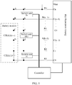
- FIG. 1 is a schematic structural diagram of a voltage collection circuit according to an embodiment of the present invention.
- the voltage collection circuit described in this embodiment of the present invention includes a battery monitoring chip, n switch units, and a controller.
- a battery module includes k battery cells: CELL(1), CELL(2), ..., and CELL(k), connected in series.
- the battery monitoring chip has n+1 differential input voltage collection channels: C0, C1, ..., and Cn, and is capable of simultaneously collecting voltages of a maximum of n battery cells.
- n and k are positive integers, k is less than or equal to n, n is known, and k is unknown.
- a value of n may be relatively large to ensure that the battery monitoring chip can be applied to as many battery modules as possible.
- the battery monitoring chip may specifically be powered by the battery module.
- a quantity of the multiple switch units is n and matches a quantity of voltage collection channels. That is, the switch units are J1, J2, ..., and Jn.
- the switch unit is connected in parallel to both the battery cell and two adjacent voltage collection channels. That is, the switch unit Ji is connected in parallel to the battery cell CELL(i).
- the switch unit Ji is any one of the n switch units, the battery cell CELL(i) is any one of the k battery cells, and i is a positive integer less than or equal to k.
- a switch unit Js is connected in parallel to voltage collection channels Cs and C(s-1), the switch unit Js is any one of the n switch units, the voltage collection channels Cs and C(s-1) are two adjacent voltage collection channels of n+1 voltage collection channels, and s is a positive integer less than or equal to n.
- a resistor may be connected in series between two terminals of a battery cell and a voltage collection channel to ensure impedance matching between the battery module and the battery monitoring chip.
- a switch unit In a default working status, a switch unit is equivalent to a diode and a conduction direction of the switch unit is opposite to a discharge current direction of a battery cell.
- a conduction direction of a switch unit Jk is from d to c in the default working status and there is a conduction voltage drop in a direction from d to c, while a discharge current direction of a battery cell CELL(k) connected in parallel to the switch unit Jk is from c to d. In this way, the battery cell CELL(k) can be prevented from discharging through a circuit C-c-d-D.
- the power-supply voltage of the battery monitoring chip is less than the highest voltage provided by the battery module. As a result, the voltage collection accuracy of the battery monitoring chip is reduced, and is very likely to be unable to meet the requirement on the voltage collection accuracy.
- the controller is connected to the battery monitoring chip and control ends of the n switch units.
- the controller communicates with the battery monitoring chip to obtain n voltages collected by the n+1 voltage collection channels of the battery monitoring chip.
- the n voltages are compared with a preset voltage threshold (for example, 0.5 volt V), separately.
- a voltage collected by two largest-numbered voltage collection channels, C(n-1) and Cn may be first compared with the preset voltage threshold. If the voltage collected by the voltage collection channels C(n-1) and Cn is less than or equal to the preset voltage threshold, the controller may determine that there is no battery cell connected between the voltage collection channels C(n-1) and Cn.
- the preset voltage threshold may be determined according to the conduction voltage drop of the switch unit in the default working status. This embodiment of the present invention is not limited.
- the controller may control, by using a control end of the switch unit Jn, the switch unit Jn to be equivalent to a conducting wire (or in other words, a voltage drop from b to a is very small and can be ignored).
- the supply voltage of the battery monitoring chip is equal to the highest voltage provided by the battery module, and the voltage collection accuracy of the battery monitoring chip is high.
- controller and the control ends of the n switch units may be connected in a direct manner, including that a control end of one switch unit corresponds to one control pin of the controller or that the control ends of the n switch units are connected to one control pin of the controller by using a communications bus (as shown in FIG. 1 or FIG. 2 ); or may be connected by using a conversion chip (for example, a serial-to-parallel chip), that is, one control pin of the controller can control the control ends of the n switch units.
- a conversion chip for example, a serial-to-parallel chip
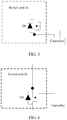
- the switch unit may use an internal structure shown in FIG. 3 , that is, a combination of a diode and a relay.
- the switch unit Jn includes a diode Dn and a relay Kn, the relay Kn is connected in parallel to the diode Dn, a control end of the relay Kn is connected to the controller.
- the controller uses the control end of the relay Kn to control the switch to be closed so as to short-circuit the diode Dn.
- the switch unit Jn is equivalent to a conducting wire.
- the switch unit may alternatively use an internal structure shown in FIG. 4 , that is, a combination of a diode and an optical insulated-gate field-effect transistor(Metal Oxide Semiconductor, MOS).
- the switch unit Jn includes a diode Dn and an optical MOS, the optical MOS is connected in parallel to the diode Dn, and a control end of the optical MOS is connected to the controller.
- the controller turns on the optical MOS by lighting a light emitting diode of the optical MOS so as to short-circuit the diode Dn.
- a conduction voltage drop of the optical MOS is very small, and the switch unit Jn can be considered as a conducting wire.
- the switch unit may alternatively use an internal structure (that is, an N-channel MOS) shown in FIG. 5 .
- the switch unit Jn includes the N-channel MOS, a control end of the N-channel MOS is connected to the controller, and a default working status of the switch unit Jn is that a conduction direction of a body diode Qn of the N-channel MOS is opposite to a discharge current direction of the battery cell CELL(n).
- the controller short-circuits the body diode Qn by controlling the N-channel MOS. In this case, a conduction voltage drop of the N-channel MOS is very small, and the switch unit Jn can be considered as a conducting wire.
- the switch unit may alternatively use an internal structure (that is, a P-channel MOS) shown in FIG. 6 .
- the switch unit Jn includes the P-channel MOS, a control end of the P-channel MOS is connected to the controller, and a default working status of the switch unit Jn is that a conduction direction of a body diode Qn of the P-channel MOS is opposite to a discharge current direction of the battery cell CELL(n).
- the controller short-circuits the body diode Qn by controlling the P-channel MOS. In this case, a conduction voltage drop of the P-channel MOS is very small, and the switch unit Jn can be considered as a conducting wire.
- a quantity of the battery monitoring chips and a quantity of the controllers may both be more than one. That is, each battery monitoring chip and each controller are respectively responsible for collection of voltages of some of the battery cells in the battery module and for control of some of the switch units.
- a voltage collection circuit provided by this embodiment of the present invention includes a battery monitoring chip, n switch units, and a controller.
- the battery monitoring chip is connected to a battery module including k battery cells, a battery cell CELL(i) is any one of the k battery cells, k is less than or equal to n, and i is less than or equal to k.
- a switch unit Ji is connected in parallel to the battery cell CELL(i), a switch unit Js is connected in parallel to voltage collection channels Cs and C(s-1), and s is less than or equal to n.
- the battery monitoring chip is configured to collect voltages of the k battery cells by using n+1 voltage collection channels.
- the controller is connected to the battery monitoring chip and control ends of the n switch units and configured to control working statuses of the n switch units according to the voltages collected by using the n+1 voltage collection channels.
- This voltage collection circuit may be adapted to different battery modules, with high compatibility and ensured high voltage collection accuracy. System costs and implementation complexity of voltage collection are reduced.
- FIG. 7 is a schematic flowchart of a circuit control method according to an embodiment of the present invention based on the voltage collection circuit in FIG. 1 .
- the circuit control method described in this embodiment uses an example in which an internal structure of a switch unit is as depicted in FIG. 3 , and includes the following steps.
- the controller collects a voltage of one battery cell by using two adjacent voltage collection channels. For instance, in FIG. 1 , voltage collection channels C0 and C1 collect a voltage of a battery cell CELL(1), ..., and voltage collection channels Ck and C(k-1) collect a voltage of a battery cell CELL(k).
- the controller may compare the collected voltages with the preset voltage threshold beginning with a largest-numbered voltage collection channel. If a voltage collected by voltage collection channels C(n-1) and Cn is less than or equal to the preset voltage threshold, the controller determines that there is no battery cell connected between the voltage collection channels C(n-1) and Cn, and controls a switch of a relay Kn of a switch unit Jn to be closed to short-circuit a diode Dn. In order to determine a quantity of battery cells in the battery module, the controller compares a voltage collected by the voltage collection channel C(n-1) and a next voltage collection channel C(n-2) with the preset voltage threshold.
- the controller determines that there is no battery cell connected between the voltage collection channels C(n-2) and C(n-1), and controls a switch of a relay K(n-1) of a switch unit J(n-1) to be closed to short-circuit a diode D(n-1). In the same way, the controller further compares a voltage collected by the voltage collection channel C(n-2) and a next voltage collection channel C(n-3) with the preset voltage threshold.
- a controller communicates with a battery monitoring chip to obtain voltages that are of k battery cells included in a battery module and that are collected by the battery monitoring chip, and determines whether the voltages collected by using the n+1 voltage collection channels are less than or equal to a preset voltage threshold; if there is a voltage collection channel by using which a voltage collected is less than or equal to the preset voltage threshold, the controller determines that there is no battery cell connected between corresponding voltage collection channels, and controls a relay of a switch unit that corresponds to the corresponding voltage collection channel to short-circuit a diode.
- the controller further determines whether a voltage collected by a next voltage collection channel is less than or equal to the preset voltage threshold, and if not, the controller may determine a value of k based on channel information of the next voltage collection channel. If yes, the controller controls a relay of a corresponding switch unit to short-circuit the diode. Controlling the voltage collection circuit based on this circuit control method may be adapted to different battery modules, with high compatibility and ensured high voltage collection accuracy. System costs and implementation complexity of voltage collection are reduced.
- the program may be stored in a computer readable storage medium. When the program runs, the processes of the methods in the embodiments are performed.
- the foregoing storage medium may include: a magnetic disk, an optical disc, a read-only memory (Read-Only Memory, ROM), or a random access memory (Random Access Memory, RAM for short).
Landscapes
- Engineering & Computer Science (AREA)
- Power Engineering (AREA)
- Manufacturing & Machinery (AREA)
- Chemical & Material Sciences (AREA)
- Chemical Kinetics & Catalysis (AREA)
- Electrochemistry (AREA)
- General Chemical & Material Sciences (AREA)
- Life Sciences & Earth Sciences (AREA)
- Sustainable Development (AREA)
- Sustainable Energy (AREA)
- Transportation (AREA)
- Mechanical Engineering (AREA)
- Physics & Mathematics (AREA)
- General Physics & Mathematics (AREA)
- Charge And Discharge Circuits For Batteries Or The Like (AREA)
- Secondary Cells (AREA)
Abstract
Description
- The present invention relates to the field of electronic technologies, and in particular, to a voltage collection circuit and a circuit control method.
- Owing to their high energy density, lithium-ion batteries are widely applied in battery systems in the fields of environmental protection, energy storage, and electric vehicles. However, strict usage restrictions have to apply to such batteries to ensure safety. A hardware circuit is required to collect data such as a voltage of each battery cell so as to monitor each battery cell in real time to check whether the usage restrictions are exceeded.
- At present, a dedicated battery monitoring chip is used mostly to collect data such as a voltage and a temperature of a battery cell. However, within different systems, voltage platforms are different, and structures and arrangements of battery modules are different. Therefore, quantities of battery cells included in all battery modules may not be exactly the same. That is, quantities of battery cells whose data needs to be collected by different battery monitoring chips may be different. Whereas different hardware circuits may be designed for battery modules with different quantities of battery cells, there is no uniform hardware circuit used to collect voltage statuses of the battery modules as a result. This increases system costs and implementation complexity.
- Embodiments of the present invention provide a voltage collection circuit and a circuit control method, so as to provide a voltage collection circuit with high adaptability and high compatibility to reduce system costs and implementation complexity of voltage collection.
- A first aspect of the embodiments of the present invention provides a voltage collection circuit, including a battery monitoring chip, n switch units, and a controller, where the battery monitoring chip includes n+1 voltage collection channels, and a battery module includes k battery cells.
- The battery monitoring chip is connected to the battery module. The battery module includes k battery cells. A battery cell CELL(i) is any one of the k battery cells, k is a positive integer less than or equal to n, and i is a positive integer less than or equal to k.
- A switch unit Ji is connected in parallel to the battery cell CELL(i), where the switch unit Ji is any one of the n switch units.
- A switch unit Js is connected in parallel to voltage collection channels Cs and C(s-1), where the switch unit Js is any one of the n switch units, the voltage collection channels Cs and C(s-1) are two adjacent voltage collection channels of n+1 voltage collection channels of the battery monitoring chip, and s is a positive integer less than or equal to n.
- The battery monitoring chip is configured to collect voltages of the k battery cells by using the n+1 voltage collection channels.
- The controller is connected to the battery monitoring chip and control ends of the n switch units and configured to control working statuses of the n switch units according to the voltages collected by using the n+1 voltage collection channels. In this way, a voltage collection circuit with high adaptability and high compatibility can be provided so as to reduce system costs and implementation complexity of voltage collection.
- Optionally, the switch unit may be a combination of a diode and a relay, the relay is connected in parallel to the diode, and a control end of the relay is connected to the controller. In a default working status of the switch unit, a conduction direction of the diode is opposite to a discharge current direction of the battery cell, so as to prevent the battery cell from discharging through the switch unit.
- The controller is configured to: when a voltage collected by a target voltage collection channel of the battery monitoring chip is less than or equal to a preset voltage threshold, control a relay of a switch unit that corresponds to the target voltage collection channel to short-circuit a diode, so as to ensure that a supply voltage of the battery monitoring chip is the highest voltage provided by the battery module, and further ensure voltage collection accuracy of the battery monitoring chip.
- Optionally, the switch unit may be a combination of a diode and an optical insulated-gate field-effect transistor MOS, the optical MOS is connected in parallel to the diode, and a control end of the optical MOS is connected to the controller. In a default working status of the switch unit, a conduction direction of the diode is opposite to a discharge current direction of the battery cell, so as to prevent the battery cell from discharging through the switch unit.
- The controller is configured to: when a voltage collected by a target voltage collection channel of the battery monitoring chip is less than or equal to a preset voltage threshold, control an optical MOS of a switch unit that corresponds to the target voltage collection channel to short-circuit a diode, so as to ensure that a supply voltage of the battery monitoring chip is the highest voltage provided by the battery module, and further ensure voltage collection accuracy of the battery monitoring chip.
- Optionally, the switch unit may be an N-channel MOS, and the N-channel MOS is connected to the controller. In a default working status of the switch unit, a conduction direction of a body diode of the N-channel MOS is opposite to a discharge current direction of the battery cell, so as to prevent the battery cell from discharging through the switch unit.
- The controller is configured to: when a voltage collected by a target voltage collection channel of the battery monitoring chip is less than or equal to a preset voltage threshold, control an N-channel MOS of a switch unit that corresponds to the target voltage collection channel to short-circuit a body diode, so as to ensure that a supply voltage of the battery monitoring chip is the highest voltage provided by the battery module, and further ensure voltage collection accuracy of the battery monitoring chip.
- Optionally, the switch unit may be a P-channel MOS, and the P-channel MOS is connected to the controller. In a default working status of the switch unit, a conduction direction of a body diode of the P-channel MOS is opposite to a discharge current direction of the battery cell, so as to prevent the battery cell from discharging through the switch unit.
- The controller is configured to: when a voltage collected by a target voltage collection channel of the battery monitoring chip is less than or equal to a preset voltage threshold. control a P-channel MOS of a switch unit that corresponds to the target voltage collection channel to short-circuit a body diode, so as to ensure that a supply voltage of the battery monitoring chip is the highest voltage provided by the battery module, and further ensure voltage collection accuracy of the battery monitoring chip.
- Optionally, the controller and the n switch units are connected directly (including a direct connection manner by using a communications bus) or connected by using a conversion chip (for example, a serial-to-parallel chip).
- A second aspect of the embodiments of the present invention provides a circuit control method, where the method is applied to a voltage collection circuit, the voltage collection circuit includes a battery monitoring chip, n switch units, and a controller, and the method includes:
- obtaining, by the controller, voltages that are of k battery cells included in the battery module and that are collected by the battery monitoring chip by using n+1 voltage collection channels; and
- controlling, by the controller, working statuses of the n switch units according to the voltages collected by using the n+1 voltage collection channels. In this way, a voltage collection circuit with high adaptability and high compatibility can be provided so as to reduce system costs and implementation complexity of voltage collection.
- Optionally, the switch unit may be a combination of a diode and a relay, the relay is connected in parallel to the diode, and a control end of the relay is connected to the controller. In a default working status of the switch unit, a conduction direction of the diode is opposite to a discharge current direction of the battery cell, so as to prevent the battery cell from discharging through the switch unit.
- Optionally, the controlling, by the controller, working statuses of the n switch units according to the voltages collected by using the n+1 voltage collection channels is specifically:
determining, by the controller, whether the voltages collected by using the n+1 voltage collection channels are less than or equal to a preset voltage threshold; and when a target voltage collection channel by using which a voltage collected is less than or equal to the preset voltage threshold is determined, controlling, by the controller, a relay of a switch unit that corresponds to the target voltage collection channel to short-circuit a diode; or going on until it is determined that there is no target voltage collection channel by using which a voltage collected is less than or equal to the preset voltage threshold, so as to ensure that a supply voltage of the battery monitoring chip is the highest voltage provided by the battery module, and further ensure voltage collection accuracy of the battery monitoring chip. - Optionally, the method further includes:
when the target voltage collection channel by using which the voltage collected is less than or equal to the preset voltage threshold is determined, determining, by the controller, a value of k, that is, a quantity of battery cells included in the battery module, according to channel information (for example, a channel number) of the target voltage collection channel. It is assumed that the target voltage collection channels are Cn and C(n-1), and that a voltage collected by voltage collection channels C(n-1) and C(n-2) is greater than the preset voltage threshold. Then, k=n-1 may be determined. - A voltage collection circuit provided by the embodiments of the present invention includes a battery monitoring chip, n switch units, and a controller. The battery monitoring chip is connected to a battery module including k battery cells, a battery cell CELL(i) is any one of the k battery cells, k is less than or equal to n, and i is less than or equal to k. A switch unit Ji is connected in parallel to the battery cell CELL(i), a switch unit Js is connected in parallel to voltage collection channels Cs and C(s-1), and s is less than or equal to n. The battery monitoring chip is configured to collect voltages of the k battery cells by using n+1 voltage collection channels. The controller is connected to the battery monitoring chip and control ends of the n switch units and configured to control working statuses of the n switch units according to the voltages collected by using the n+1 voltage collection channels. In this way, a voltage collection circuit with high adaptability and high compatibility can be provided so as to reduce system costs and implementation complexity of voltage collection.
- To describe the technical solutions in the embodiments of the present invention more clearly, the following briefly describes the accompanying drawings required for describing the embodiments. Apparently, the accompanying drawings in the following description show merely some embodiments of the present invention, and a person of ordinary skill in the art may still derive other drawings from these accompanying drawings without creative efforts.
-
FIG. 1 is a schematic structural diagram of a voltage collection circuit according to an embodiment of the present invention; -
FIG. 2 is a schematic structural diagram of another voltage collection circuit according to an embodiment of the present invention; -
FIG. 3 is a schematic structural diagram of a switch unit according to an embodiment of the present invention; -
FIG. 4 is a schematic structural diagram of another switch unit according to an embodiment of the present invention; -
FIG. 5 is a schematic structural diagram of still another switch unit according to an embodiment of the present invention; -
FIG. 6 is a schematic structural diagram of yet another switch unit according to an embodiment of the present invention; and -
FIG. 7 is a schematic flowchart of a circuit control method according to an embodiment of the present invention. - The following clearly and completely describes the technical solutions in the embodiments of the present invention with reference to the accompanying drawings in the embodiments of the present invention. Apparently, the described embodiments are merely some but not all of the embodiments of the present invention. All other embodiments obtained by a person of ordinary skill in the art based on the embodiments of the present invention without creative efforts shall fall within the protection scope of the present invention.
- Referring to
FIG. 1, FIG. 1 is a schematic structural diagram of a voltage collection circuit according to an embodiment of the present invention. The voltage collection circuit described in this embodiment of the present invention includes a battery monitoring chip, n switch units, and a controller. - A battery module includes k battery cells: CELL(1), CELL(2), ..., and CELL(k), connected in series.
- The battery monitoring chip has n+1 differential input voltage collection channels: C0, C1, ..., and Cn, and is capable of simultaneously collecting voltages of a maximum of n battery cells.
- n and k are positive integers, k is less than or equal to n, n is known, and k is unknown. Preferably, a value of n may be relatively large to ensure that the battery monitoring chip can be applied to as many battery modules as possible. The battery monitoring chip may specifically be powered by the battery module.
- A quantity of the multiple switch units is n and matches a quantity of voltage collection channels. That is, the switch units are J1, J2, ..., and Jn.
- Specifically, the switch unit is connected in parallel to both the battery cell and two adjacent voltage collection channels. That is, the switch unit Ji is connected in parallel to the battery cell CELL(i). The switch unit Ji is any one of the n switch units, the battery cell CELL(i) is any one of the k battery cells, and i is a positive integer less than or equal to k. A switch unit Js is connected in parallel to voltage collection channels Cs and C(s-1), the switch unit Js is any one of the n switch units, the voltage collection channels Cs and C(s-1) are two adjacent voltage collection channels of n+1 voltage collection channels, and s is a positive integer less than or equal to n. The battery monitoring chip is connected to the k battery cells included in the battery module, and is configured to collect voltages of the k battery cells by using the n+1 voltage collection channels. That is, voltage collection channels C0 and C1 are used to collect a voltage of a battery cell CELL(1), voltage collection channels C1 and C2 are used to collect a voltage of a battery cell CELL(2), ..., and if the battery module includes n battery cells, that is, k=n, voltage collection channels C(n-1) and Cn are used to collect a voltage of a battery cell CELL(n), as shown in
FIG. 2 . - Preferably, a resistor may be connected in series between two terminals of a battery cell and a voltage collection channel to ensure impedance matching between the battery module and the battery monitoring chip.
- In a default working status, a switch unit is equivalent to a diode and a conduction direction of the switch unit is opposite to a discharge current direction of a battery cell. For example, a conduction direction of a switch unit Jk is from d to c in the default working status and there is a conduction voltage drop in a direction from d to c, while a discharge current direction of a battery cell CELL(k) connected in parallel to the switch unit Jk is from c to d. In this way, the battery cell CELL(k) can be prevented from discharging through a circuit C-c-d-D.
- The battery monitoring chip is powered by the battery module. Therefore, a power-supply pin Vbat is connected to a point between a switch unit Jn and a resistor Rn. If k=n, as shown in
FIG. 2 , a potential of the power-supply pin Vbat is equal to a potential of the positive terminal of the battery cell CELL(n). That is, a supply voltage of the battery monitoring chip is equal to the highest voltage provided by the battery module. In this case, voltage collection accuracy of the battery monitoring chip is high enough to meet a requirement on the voltage collection accuracy. - However, when the quantity of battery cells included in the battery module is less than n, assuming that k=n-1, there is a conduction voltage drop in the switch unit Jn in a direction from b to a and the conduction voltage drop is generally not ignorable. Therefore, in this case, the power-supply voltage of the battery monitoring chip is less than the highest voltage provided by the battery module. As a result, the voltage collection accuracy of the battery monitoring chip is reduced, and is very likely to be unable to meet the requirement on the voltage collection accuracy.
- The controller is connected to the battery monitoring chip and control ends of the n switch units. The controller communicates with the battery monitoring chip to obtain n voltages collected by the n+1 voltage collection channels of the battery monitoring chip. The n voltages are compared with a preset voltage threshold (for example, 0.5 volt V), separately. In order to reduce time for the comparison, a voltage collected by two largest-numbered voltage collection channels, C(n-1) and Cn, may be first compared with the preset voltage threshold. If the voltage collected by the voltage collection channels C(n-1) and Cn is less than or equal to the preset voltage threshold, the controller may determine that there is no battery cell connected between the voltage collection channels C(n-1) and Cn.
- The preset voltage threshold may be determined according to the conduction voltage drop of the switch unit in the default working status. This embodiment of the present invention is not limited.
- Further, the controller compares a voltage collected by voltage collection channels C(n-2) and C(n-1) with the preset voltage threshold. If the voltage collected by the voltage collection channels C(n-2) and C(n-1) is greater than the preset voltage threshold, the controller may determine that a battery cell is connected between the voltage collection channels C(n-2) and C(n-1). In this case, the controller may determine that k=n-1.
- Further, because no battery cell is connected between the voltage collection channels C(n-1) and Cn, the controller may control, by using a control end of the switch unit Jn, the switch unit Jn to be equivalent to a conducting wire (or in other words, a voltage drop from b to a is very small and can be ignored). In this case, it can be considered that the supply voltage of the battery monitoring chip is equal to the highest voltage provided by the battery module, and the voltage collection accuracy of the battery monitoring chip is high.
- It should be noted that the controller and the control ends of the n switch units may be connected in a direct manner, including that a control end of one switch unit corresponds to one control pin of the controller or that the control ends of the n switch units are connected to one control pin of the controller by using a communications bus (as shown in
FIG. 1 orFIG. 2 ); or may be connected by using a conversion chip (for example, a serial-to-parallel chip), that is, one control pin of the controller can control the control ends of the n switch units. This embodiment of the present invention is not limited. - The switch unit may use an internal structure shown in
FIG. 3 , that is, a combination of a diode and a relay. For example, the switch unit Jn includes a diode Dn and a relay Kn, the relay Kn is connected in parallel to the diode Dn, a control end of the relay Kn is connected to the controller. The controller uses the control end of the relay Kn to control the switch to be closed so as to short-circuit the diode Dn. In this case, the switch unit Jn is equivalent to a conducting wire. - In some feasible implementations, the switch unit may alternatively use an internal structure shown in
FIG. 4 , that is, a combination of a diode and an optical insulated-gate field-effect transistor(Metal Oxide Semiconductor, MOS). For example, the switch unit Jn includes a diode Dn and an optical MOS, the optical MOS is connected in parallel to the diode Dn, and a control end of the optical MOS is connected to the controller. The controller turns on the optical MOS by lighting a light emitting diode of the optical MOS so as to short-circuit the diode Dn. In this case, a conduction voltage drop of the optical MOS is very small, and the switch unit Jn can be considered as a conducting wire. - In some feasible implementations, the switch unit may alternatively use an internal structure (that is, an N-channel MOS) shown in
FIG. 5 . For example, the switch unit Jn includes the N-channel MOS, a control end of the N-channel MOS is connected to the controller, and a default working status of the switch unit Jn is that a conduction direction of a body diode Qn of the N-channel MOS is opposite to a discharge current direction of the battery cell CELL(n). The controller short-circuits the body diode Qn by controlling the N-channel MOS. In this case, a conduction voltage drop of the N-channel MOS is very small, and the switch unit Jn can be considered as a conducting wire. - In some feasible implementations, the switch unit may alternatively use an internal structure (that is, a P-channel MOS) shown in
FIG. 6 . For example, the switch unit Jn includes the P-channel MOS, a control end of the P-channel MOS is connected to the controller, and a default working status of the switch unit Jn is that a conduction direction of a body diode Qn of the P-channel MOS is opposite to a discharge current direction of the battery cell CELL(n). The controller short-circuits the body diode Qn by controlling the P-channel MOS. In this case, a conduction voltage drop of the P-channel MOS is very small, and the switch unit Jn can be considered as a conducting wire. - In some feasible implementations, a quantity of the battery monitoring chips and a quantity of the controllers may both be more than one. That is, each battery monitoring chip and each controller are respectively responsible for collection of voltages of some of the battery cells in the battery module and for control of some of the switch units.
- A voltage collection circuit provided by this embodiment of the present invention includes a battery monitoring chip, n switch units, and a controller. The battery monitoring chip is connected to a battery module including k battery cells, a battery cell CELL(i) is any one of the k battery cells, k is less than or equal to n, and i is less than or equal to k. A switch unit Ji is connected in parallel to the battery cell CELL(i), a switch unit Js is connected in parallel to voltage collection channels Cs and C(s-1), and s is less than or equal to n. The battery monitoring chip is configured to collect voltages of the k battery cells by using n+1 voltage collection channels. The controller is connected to the battery monitoring chip and control ends of the n switch units and configured to control working statuses of the n switch units according to the voltages collected by using the n+1 voltage collection channels. This voltage collection circuit may be adapted to different battery modules, with high compatibility and ensured high voltage collection accuracy. System costs and implementation complexity of voltage collection are reduced.
- Referring to
FIG. 7, FIG. 7 is a schematic flowchart of a circuit control method according to an embodiment of the present invention based on the voltage collection circuit inFIG. 1 . The circuit control method described in this embodiment uses an example in which an internal structure of a switch unit is as depicted inFIG. 3 , and includes the following steps. - 701: The controller obtains voltages that are of k battery cells included in a battery module and that are collected by a battery monitoring chip by using n+1 voltage collection channels.
- 702: The controller determines whether the voltages collected by using the n+1 voltage collection channels are less than or equal to a preset voltage threshold; and if yes, executes
step 703; or if no, ends this process. - 703: The controller controls a relay of a switch unit that corresponds to a voltage collection channel by using which a voltage collected is less than or equal to the preset voltage threshold to short-circuit a diode.
- 704: The controller determines whether a voltage collected by a next voltage collection channel is less than or equal to the preset voltage threshold; and if yes, goes back to execute
step 703; or if no, executesstep 705. - 705: The controller determines a value of k according to channel information of the next voltage collection channel.
- It should be noted that the controller collects a voltage of one battery cell by using two adjacent voltage collection channels. For instance, in
FIG. 1 , voltage collection channels C0 and C1 collect a voltage of a battery cell CELL(1), ..., and voltage collection channels Ck and C(k-1) collect a voltage of a battery cell CELL(k). - Preferably, the controller may compare the collected voltages with the preset voltage threshold beginning with a largest-numbered voltage collection channel. If a voltage collected by voltage collection channels C(n-1) and Cn is less than or equal to the preset voltage threshold, the controller determines that there is no battery cell connected between the voltage collection channels C(n-1) and Cn, and controls a switch of a relay Kn of a switch unit Jn to be closed to short-circuit a diode Dn. In order to determine a quantity of battery cells in the battery module, the controller compares a voltage collected by the voltage collection channel C(n-1) and a next voltage collection channel C(n-2) with the preset voltage threshold. If the voltage collected by the voltage collection channels C(n-2) and C(n-1) is greater than the preset voltage threshold, the controller determines that there is a battery cell connected between the voltage collection channels C(n-2) and C(n-1), and may determine that k=n-1 according to channel information (for example, a channel number n-2) of the next voltage collection channel C(n-2). If the voltage collected by the voltage collection channels C(n-1) and Cn is greater than the preset voltage threshold, the controller may directly determine that the quantity of battery cells in the battery module is n.
- Further, if the voltage collected by the voltage collection channel C(n-1) and the next voltage collection channel C(n-2) is also less than or equal to the preset voltage threshold, the controller determines that there is no battery cell connected between the voltage collection channels C(n-2) and C(n-1), and controls a switch of a relay K(n-1) of a switch unit J(n-1) to be closed to short-circuit a diode D(n-1). In the same way, the controller further compares a voltage collected by the voltage collection channel C(n-2) and a next voltage collection channel C(n-3) with the preset voltage threshold. If the voltage collected by voltage collection channels C(n-3) and C(n-2) is greater than the preset voltage threshold, the controller determines that there is a battery cell connected between the voltage collection channels C(n-3) and C(n-2), and may determine that k=n-2 according to channel information (for example, a channel number n-3) of the next voltage collection channel C(n-3).
- Further, if the voltage collected by the voltage collection channel C(n-2) and the next voltage collection channel C(n-3) is also less than or equal to the preset voltage threshold, the controller repeats actions similar to the foregoing ones until all voltage collection channels by which voltages collected are less than or equal to the preset voltage threshold are determined, controls a corresponding switch unit, and determines the value of k; or the controller repeats similar actions until it is determined that there is no voltage collection channel by using which a voltage collected is less than or equal to the preset voltage threshold, and determines that k=n.
- In this embodiment of the present invention, a controller communicates with a battery monitoring chip to obtain voltages that are of k battery cells included in a battery module and that are collected by the battery monitoring chip, and determines whether the voltages collected by using the n+1 voltage collection channels are less than or equal to a preset voltage threshold; if there is a voltage collection channel by using which a voltage collected is less than or equal to the preset voltage threshold, the controller determines that there is no battery cell connected between corresponding voltage collection channels, and controls a relay of a switch unit that corresponds to the corresponding voltage collection channel to short-circuit a diode. The controller further determines whether a voltage collected by a next voltage collection channel is less than or equal to the preset voltage threshold, and if not, the controller may determine a value of k based on channel information of the next voltage collection channel. If yes, the controller controls a relay of a corresponding switch unit to short-circuit the diode. Controlling the voltage collection circuit based on this circuit control method may be adapted to different battery modules, with high compatibility and ensured high voltage collection accuracy. System costs and implementation complexity of voltage collection are reduced.
- A person of ordinary skill in the art may understand that all or some of the processes of the methods in the embodiments may be implemented by a computer program instructing relevant hardware. The program may be stored in a computer readable storage medium. When the program runs, the processes of the methods in the embodiments are performed. The foregoing storage medium may include: a magnetic disk, an optical disc, a read-only memory (Read-Only Memory, ROM), or a random access memory (Random Access Memory, RAM for short).
- In this specification, specific examples are used to describe the principle and implementations of the present invention, and the description of the embodiments is only intended to help understand the method and core idea of the present invention. In addition, a person of ordinary skill in the art may, based on the idea of the present invention, make modifications to the specific implementations and the application scope. Therefore, the content of this specification shall not be construed as a limitation to the present invention.
Claims (10)
- A voltage collection circuit, comprising a battery monitoring chip, n switch units, and a controller, wherein n is a positive integer;
the battery monitoring chip is connected to a battery module, wherein the battery module comprises k battery cells, a battery cell CELL(i) is any one of the k battery cells, k is a positive integer less than or equal to n, and i is a positive integer less than or equal to k;
a switch unit Ji is connected in parallel to the battery cell CELL(i), wherein the switch unit Ji is any one of the n switch units;
a switch unit Js is connected in parallel to voltage collection channels Cs and C(s-1), wherein the switch unit Js is any one of the n switch units, the voltage collection channels Cs and C(s-1) are any two adjacent voltage collection channels of n+1 voltage collection channels of the battery monitoring chip, and s is a positive integer less than or equal to n;
the battery monitoring chip is configured to collect voltages of the k battery cells by using the n+1 voltage collection channels; and
the controller is connected to the battery monitoring chip and control ends of the n switch units and configured to control working statuses of the n switch units according to the voltages collected by using the n+1 voltage collection channels. - The circuit according to claim 1, wherein
the switch unit comprises a diode and a relay, the relay is connected in parallel to the diode, a control end of the relay is connected to the controller, and a default working status of the switch unit is that a conduction direction of the diode is opposite to a discharge current direction of the battery cell; and
the controller is configured to: when a voltage collected by using a target voltage collection channel of the battery monitoring chip is less than or equal to a preset voltage threshold, control a relay of a switch unit that corresponds to the target voltage collection channel to short-circuit a diode. - The circuit according to claim 1, wherein
the switch unit comprises a diode and an optical insulated-gate field-effect transistor MOS, the optical MOS is connected in parallel to the diode, a control end of the optical MOS is connected to the controller, and a default working status of the switch unit is that a conduction direction of the diode is opposite to a discharge current direction of the battery cell; and
the controller is configured to: when a voltage collected by a target voltage collection channel of the battery monitoring chip is less than or equal to a preset voltage threshold, control an optical MOS of a switch unit that corresponds to the target voltage collection channel to short-circuit a diode. - The circuit according to claim 1, wherein
the switch unit comprises an N-channel MOS, and a control end of the N-channel MOS is connected to the controller, and a default working status of the switch unit is that a conduction direction of a body diode of the N-channel MOS is opposite to a discharge current direction of the battery cell; and
the controller is configured to: when a voltage collected by a target voltage collection channel of the battery monitoring chip is less than or equal to a preset voltage threshold, control an N-channel MOS of a switch unit that corresponds to the target voltage collection channel to short-circuit a body diode. - The circuit according to claim 1, wherein
the switch unit comprises a P-channel MOS, and a control end of the P-channel MOS is connected to the controller, and a default working status of the switch unit is that a conduction direction of a body diode of the P-channel MOS is opposite to a discharge current direction of the battery cell; and
the controller is configured to: when a voltage collected by a target voltage collection channel of the battery monitoring chip is less than or equal to a preset voltage threshold, control a P-channel MOS of a switch unit that corresponds to the target voltage collection channel to short-circuit a body diode. - The circuit according to any one of claims 1 to 5, wherein
the controller and the n switch units are connected directly or connected by using a conversion chip. - A circuit control method, wherein the method is applied to a voltage collection circuit, the voltage collection circuit comprises a battery monitoring chip, n switch units, and a controller, n is a positive integer, and the method comprises:obtaining, by the controller, voltages that are of k battery cells comprised in a battery module and that are collected by the battery monitoring chip by using n+1 voltage collection channels, wherein k is a positive integer less than or equal to n; andcontrolling, by the controller, working statuses of the n switch units according to the voltages collected by using the n+1 voltage collection channels.
- The method according to claim 7, wherein
the switch unit comprises a diode and a relay, the relay is connected in parallel to the diode, a control end of the relay is connected to the controller, and a default working status of the switch unit is that a conduction direction of the diode is opposite to a discharge current direction of the battery cell. - The method according to claim 8, wherein the controlling, by the controller, working statuses of the n switch units according to the voltages collected by using the n+1 voltage collection channels is specifically:determining, by the controller, whether the voltages collected by using the n+1 voltage collection channels are less than or equal to a preset voltage threshold; andwhen a target voltage collection channel by using which a voltage collected is less than or equal to the preset voltage threshold is determined, controlling, by the controller, a relay of a switch unit that corresponds to the target voltage collection channel to short-circuit a diode.
- The method according to claim 9, further comprising:
when the target voltage collection channel by using which the voltage collected is less than or equal to the preset voltage threshold is determined, determining, by the controller, a value of k according to channel information of the target voltage collection channel.
Applications Claiming Priority (2)
| Application Number | Priority Date | Filing Date | Title |
|---|---|---|---|
| CN201610289360.7A CN107332292B (en) | 2016-04-29 | 2016-04-29 | Voltage acquisition circuit and circuit control method |
| PCT/CN2016/102407 WO2017185671A1 (en) | 2016-04-29 | 2016-10-18 | Voltage collecting circuit and circuit control method |
Publications (2)
| Publication Number | Publication Date |
|---|---|
| EP3343724A1 true EP3343724A1 (en) | 2018-07-04 |
| EP3343724A4 EP3343724A4 (en) | 2018-10-24 |
Family
ID=60161817
Family Applications (1)
| Application Number | Title | Priority Date | Filing Date |
|---|---|---|---|
| EP16900179.9A Pending EP3343724A4 (en) | 2016-04-29 | 2016-10-18 | Voltage collecting circuit and circuit control method |
Country Status (4)
| Country | Link |
|---|---|
| US (1) | US10819123B2 (en) |
| EP (1) | EP3343724A4 (en) |
| CN (1) | CN107332292B (en) |
| WO (1) | WO2017185671A1 (en) |
Families Citing this family (5)
| Publication number | Priority date | Publication date | Assignee | Title |
|---|---|---|---|---|
| TWI671987B (en) * | 2018-09-10 | 2019-09-11 | 捷佳科技股份有限公司 | Wireless power transmitting unit |
| CN109309398B (en) * | 2018-09-30 | 2023-09-19 | 联想(北京)有限公司 | A processing method and power supply device |
| CN110456280B (en) * | 2019-08-16 | 2021-12-21 | 罗宜恒 | Battery use data online monitoring device and method |
| CN116500483A (en) * | 2022-01-18 | 2023-07-28 | 宁德时代新能源科技股份有限公司 | Fault diagnosis method |
| CN115614222B (en) * | 2022-10-17 | 2025-11-21 | 东方电气风电股份有限公司 | Control circuit and method for switching battery pitch collection failure of pitch control system into alternating current pitch collection |
Family Cites Families (16)
| Publication number | Priority date | Publication date | Assignee | Title |
|---|---|---|---|---|
| US6046514A (en) * | 1997-07-25 | 2000-04-04 | 3M Innovative Properties Company | Bypass apparatus and method for series connected energy storage devices |
| JPH11234916A (en) * | 1998-02-16 | 1999-08-27 | Rohm Co Ltd | Lithium ion battery pack |
| FR2880995B1 (en) * | 2005-01-14 | 2007-04-06 | Pellenc Sa | METHOD FOR BALANCED LOADING OF LITHIUM-ION OR POLYMER LITHIUM BATTERY |
| KR101182431B1 (en) * | 2010-10-12 | 2012-09-12 | 삼성에스디아이 주식회사 | Battery pack, controlling method of the same, and power storage system including the battery pack |
| CN202084959U (en) * | 2011-05-18 | 2011-12-21 | 上海恒动汽车电池有限公司 | A lithium-ion battery pack equalization system |
| CN202633971U (en) * | 2011-05-26 | 2012-12-26 | 韩竞科 | Battery control circuit |
| WO2013024541A1 (en) * | 2011-08-18 | 2013-02-21 | 日立ビークルエナジー株式会社 | Cell monitoring device and cell control device provided with same |
| CN202231461U (en) * | 2011-09-15 | 2012-05-23 | 金华职业技术学院 | Charge-discharge balance control system for power battery pack |
| WO2014024452A1 (en) * | 2012-08-09 | 2014-02-13 | 三洋電機株式会社 | Battery system, and electric vehicle and electricity storage device both having said battery system |
| JP6234127B2 (en) | 2012-10-11 | 2017-11-22 | 株式会社Gsユアサ | Power storage device |
| KR101630002B1 (en) * | 2012-11-12 | 2016-06-21 | 삼성에스디아이 주식회사 | Energy storage system |
| US9362757B2 (en) * | 2012-12-31 | 2016-06-07 | Seeo, Inc. | Solid-state active switch matrix for high energy, moderate power battery systems |
| US20140285936A1 (en) * | 2013-03-20 | 2014-09-25 | Magna E-Car Systems Of America, Inc. | Battery management system for electric vehicle |
| JP5910889B2 (en) * | 2013-10-01 | 2016-04-27 | トヨタ自動車株式会社 | Power storage system |
| JP2017531983A (en) * | 2014-10-13 | 2017-10-26 | 24エム・テクノロジーズ・インコーポレイテッド24M Technologies, Inc. | System and method for series battery charging and forming |
| JP6828296B2 (en) * | 2016-08-09 | 2021-02-10 | 株式会社Gsユアサ | Power storage device and charge control method for power storage device |
-
2016
- 2016-04-29 CN CN201610289360.7A patent/CN107332292B/en active Active
- 2016-10-18 WO PCT/CN2016/102407 patent/WO2017185671A1/en not_active Ceased
- 2016-10-18 EP EP16900179.9A patent/EP3343724A4/en active Pending
-
2018
- 2018-04-09 US US15/948,612 patent/US10819123B2/en active Active
Also Published As
| Publication number | Publication date |
|---|---|
| CN107332292A (en) | 2017-11-07 |
| WO2017185671A1 (en) | 2017-11-02 |
| EP3343724A4 (en) | 2018-10-24 |
| CN107332292B (en) | 2021-02-26 |
| US20180226814A1 (en) | 2018-08-09 |
| US10819123B2 (en) | 2020-10-27 |
Similar Documents
| Publication | Publication Date | Title |
|---|---|---|
| US10819123B2 (en) | Voltage collection circuit and circuit control method | |
| KR101589198B1 (en) | Apparatus and method for diagnosis of cell balancing circuit | |
| TWI672889B (en) | Control device, power storage device, power storage system, and recording medium | |
| US10297855B2 (en) | Rechargeable multi-cell battery | |
| US9876374B2 (en) | Device for controlling charging voltage | |
| EP2219281A2 (en) | Circuit and method for cell balancing | |
| US10464436B2 (en) | Battery system for a hybrid vehicle | |
| JP2014512788A (en) | Charge equalization system for batteries | |
| US11946974B2 (en) | Parallel battery relay diagnostic device and method | |
| US10587126B2 (en) | Power storage device, power storage control device, and power storage control method | |
| CN111095722B (en) | Battery unit and battery unit control method | |
| US20140176080A1 (en) | Load/charger detection circuit, battery management system comprising the same and driving method thereof | |
| US11293985B2 (en) | Switch diagnosing apparatus and method | |
| EP3573209A1 (en) | Control circuit compatible with battery power supply and external power supply | |
| KR102861413B1 (en) | Battery control system, battery pack, electric vehicle, and control method for the battery control system | |
| US10525847B2 (en) | Power switch, battery system and method for operating a power switch | |
| US11095150B2 (en) | Emergency dimming apparatus | |
| KR101858321B1 (en) | Apparatus and method for diagnosis of cell balancing circuit | |
| EP3337002B1 (en) | Battery system and control unit for a battery system | |
| EP2592741A1 (en) | Integrated circuit adapted to perform power path control in a mobile equipment | |
| KR20180106939A (en) | Battery pack and method of connecting the same to external battery systems in parallel | |
| US9337678B2 (en) | Battery block, and power source system | |
| CN112219306B (en) | BMS identification system and method | |
| US10658850B2 (en) | Battery module and battery system having the same | |
| US9853473B2 (en) | Battery pack assembly and method |
Legal Events
| Date | Code | Title | Description |
|---|---|---|---|
| STAA | Information on the status of an ep patent application or granted ep patent |
Free format text: STATUS: THE INTERNATIONAL PUBLICATION HAS BEEN MADE |
|
| PUAI | Public reference made under article 153(3) epc to a published international application that has entered the european phase |
Free format text: ORIGINAL CODE: 0009012 |
|
| STAA | Information on the status of an ep patent application or granted ep patent |
Free format text: STATUS: REQUEST FOR EXAMINATION WAS MADE |
|
| 17P | Request for examination filed |
Effective date: 20180329 |
|
| AK | Designated contracting states |
Kind code of ref document: A1 Designated state(s): AL AT BE BG CH CY CZ DE DK EE ES FI FR GB GR HR HU IE IS IT LI LT LU LV MC MK MT NL NO PL PT RO RS SE SI SK SM TR |
|
| AX | Request for extension of the european patent |
Extension state: BA ME |
|
| A4 | Supplementary search report drawn up and despatched |
Effective date: 20180924 |
|
| RIC1 | Information provided on ipc code assigned before grant |
Ipc: H02J 7/00 20060101AFI20180918BHEP |
|
| STAA | Information on the status of an ep patent application or granted ep patent |
Free format text: STATUS: EXAMINATION IS IN PROGRESS |
|
| 17Q | First examination report despatched |
Effective date: 20190619 |
|
| DAV | Request for validation of the european patent (deleted) | ||
| DAX | Request for extension of the european patent (deleted) | ||
| RAP1 | Party data changed (applicant data changed or rights of an application transferred) |
Owner name: SHENZHEN YINWANG INTELLIGENTTECHNOLOGIES CO., LTD. |
|
| GRAP | Despatch of communication of intention to grant a patent |
Free format text: ORIGINAL CODE: EPIDOSNIGR1 |
|
| STAA | Information on the status of an ep patent application or granted ep patent |
Free format text: STATUS: GRANT OF PATENT IS INTENDED |