EP3343698A1 - Wireless signal transmission antenna, wireless signal reception antenna, wireless signal transmission/reception system, wireless signal transmission method, and wireless signal reception method - Google Patents
Wireless signal transmission antenna, wireless signal reception antenna, wireless signal transmission/reception system, wireless signal transmission method, and wireless signal reception method Download PDFInfo
- Publication number
- EP3343698A1 EP3343698A1 EP15905291.9A EP15905291A EP3343698A1 EP 3343698 A1 EP3343698 A1 EP 3343698A1 EP 15905291 A EP15905291 A EP 15905291A EP 3343698 A1 EP3343698 A1 EP 3343698A1
- Authority
- EP
- European Patent Office
- Prior art keywords
- helical beam
- helical
- signal
- antenna
- signals
- Prior art date
- Legal status (The legal status is an assumption and is not a legal conclusion. Google has not performed a legal analysis and makes no representation as to the accuracy of the status listed.)
- Granted
Links
- 238000000034 method Methods 0.000 title claims description 19
- 230000008054 signal transmission Effects 0.000 title 3
- 238000009826 distribution Methods 0.000 claims description 93
- 230000005672 electromagnetic field Effects 0.000 claims description 52
- 230000010287 polarization Effects 0.000 claims description 7
- 239000012141 concentrate Substances 0.000 claims description 6
- 230000007423 decrease Effects 0.000 claims description 2
- 238000010586 diagram Methods 0.000 description 20
- 239000011295 pitch Substances 0.000 description 16
- 239000011159 matrix material Substances 0.000 description 14
- 230000005855 radiation Effects 0.000 description 12
- 230000005540 biological transmission Effects 0.000 description 11
- 230000000593 degrading effect Effects 0.000 description 3
- 230000003247 decreasing effect Effects 0.000 description 2
- 230000000694 effects Effects 0.000 description 2
- 230000015654 memory Effects 0.000 description 2
- 230000003287 optical effect Effects 0.000 description 2
- 230000035945 sensitivity Effects 0.000 description 2
- 229910052782 aluminium Inorganic materials 0.000 description 1
- XAGFODPZIPBFFR-UHFFFAOYSA-N aluminium Chemical compound [Al] XAGFODPZIPBFFR-UHFFFAOYSA-N 0.000 description 1
- 230000015556 catabolic process Effects 0.000 description 1
- 238000006731 degradation reaction Methods 0.000 description 1
- 230000006870 function Effects 0.000 description 1
- 230000002452 interceptive effect Effects 0.000 description 1
- 239000007769 metal material Substances 0.000 description 1
- 239000013307 optical fiber Substances 0.000 description 1
- 239000004065 semiconductor Substances 0.000 description 1
- 229910001220 stainless steel Inorganic materials 0.000 description 1
- 239000010935 stainless steel Substances 0.000 description 1
Images


Classifications
-
- H—ELECTRICITY
- H01—ELECTRIC ELEMENTS
- H01Q—ANTENNAS, i.e. RADIO AERIALS
- H01Q19/00—Combinations of primary active antenna elements and units with secondary devices, e.g. with quasi-optical devices, for giving the antenna a desired directional characteristic
- H01Q19/10—Combinations of primary active antenna elements and units with secondary devices, e.g. with quasi-optical devices, for giving the antenna a desired directional characteristic using reflecting surfaces
- H01Q19/12—Combinations of primary active antenna elements and units with secondary devices, e.g. with quasi-optical devices, for giving the antenna a desired directional characteristic using reflecting surfaces wherein the surfaces are concave
- H01Q19/17—Combinations of primary active antenna elements and units with secondary devices, e.g. with quasi-optical devices, for giving the antenna a desired directional characteristic using reflecting surfaces wherein the surfaces are concave the primary radiating source comprising two or more radiating elements
-
- H—ELECTRICITY
- H01—ELECTRIC ELEMENTS
- H01Q—ANTENNAS, i.e. RADIO AERIALS
- H01Q15/00—Devices for reflection, refraction, diffraction or polarisation of waves radiated from an antenna, e.g. quasi-optical devices
- H01Q15/14—Reflecting surfaces; Equivalent structures
- H01Q15/16—Reflecting surfaces; Equivalent structures curved in two dimensions, e.g. paraboloidal
-
- H—ELECTRICITY
- H01—ELECTRIC ELEMENTS
- H01Q—ANTENNAS, i.e. RADIO AERIALS
- H01Q15/00—Devices for reflection, refraction, diffraction or polarisation of waves radiated from an antenna, e.g. quasi-optical devices
- H01Q15/14—Reflecting surfaces; Equivalent structures
- H01Q15/22—Reflecting surfaces; Equivalent structures functioning also as polarisation filter
-
- H—ELECTRICITY
- H01—ELECTRIC ELEMENTS
- H01Q—ANTENNAS, i.e. RADIO AERIALS
- H01Q19/00—Combinations of primary active antenna elements and units with secondary devices, e.g. with quasi-optical devices, for giving the antenna a desired directional characteristic
- H01Q19/06—Combinations of primary active antenna elements and units with secondary devices, e.g. with quasi-optical devices, for giving the antenna a desired directional characteristic using refracting or diffracting devices, e.g. lens
- H01Q19/062—Combinations of primary active antenna elements and units with secondary devices, e.g. with quasi-optical devices, for giving the antenna a desired directional characteristic using refracting or diffracting devices, e.g. lens for focusing
-
- H—ELECTRICITY
- H01—ELECTRIC ELEMENTS
- H01Q—ANTENNAS, i.e. RADIO AERIALS
- H01Q19/00—Combinations of primary active antenna elements and units with secondary devices, e.g. with quasi-optical devices, for giving the antenna a desired directional characteristic
- H01Q19/10—Combinations of primary active antenna elements and units with secondary devices, e.g. with quasi-optical devices, for giving the antenna a desired directional characteristic using reflecting surfaces
- H01Q19/18—Combinations of primary active antenna elements and units with secondary devices, e.g. with quasi-optical devices, for giving the antenna a desired directional characteristic using reflecting surfaces having two or more spaced reflecting surfaces
- H01Q19/19—Combinations of primary active antenna elements and units with secondary devices, e.g. with quasi-optical devices, for giving the antenna a desired directional characteristic using reflecting surfaces having two or more spaced reflecting surfaces comprising one main concave reflecting surface associated with an auxiliary reflecting surface
-
- H—ELECTRICITY
- H01—ELECTRIC ELEMENTS
- H01Q—ANTENNAS, i.e. RADIO AERIALS
- H01Q21/00—Antenna arrays or systems
- H01Q21/06—Arrays of individually energised antenna units similarly polarised and spaced apart
- H01Q21/20—Arrays of individually energised antenna units similarly polarised and spaced apart the units being spaced along or adjacent to a curvilinear path
-
- H—ELECTRICITY
- H01—ELECTRIC ELEMENTS
- H01Q—ANTENNAS, i.e. RADIO AERIALS
- H01Q25/00—Antennas or antenna systems providing at least two radiating patterns
- H01Q25/04—Multimode antennas
-
- H—ELECTRICITY
- H01—ELECTRIC ELEMENTS
- H01Q—ANTENNAS, i.e. RADIO AERIALS
- H01Q3/00—Arrangements for changing or varying the orientation or the shape of the directional pattern of the waves radiated from an antenna or antenna system
- H01Q3/26—Arrangements for changing or varying the orientation or the shape of the directional pattern of the waves radiated from an antenna or antenna system varying the relative phase or relative amplitude of energisation between two or more active radiating elements; varying the distribution of energy across a radiating aperture
- H01Q3/30—Arrangements for changing or varying the orientation or the shape of the directional pattern of the waves radiated from an antenna or antenna system varying the relative phase or relative amplitude of energisation between two or more active radiating elements; varying the distribution of energy across a radiating aperture varying the relative phase between the radiating elements of an array
- H01Q3/34—Arrangements for changing or varying the orientation or the shape of the directional pattern of the waves radiated from an antenna or antenna system varying the relative phase or relative amplitude of energisation between two or more active radiating elements; varying the distribution of energy across a radiating aperture varying the relative phase between the radiating elements of an array by electrical means
- H01Q3/40—Arrangements for changing or varying the orientation or the shape of the directional pattern of the waves radiated from an antenna or antenna system varying the relative phase or relative amplitude of energisation between two or more active radiating elements; varying the distribution of energy across a radiating aperture varying the relative phase between the radiating elements of an array by electrical means with phasing matrix
Definitions
- the present invention relates to a radio signal transmitting antenna, a radio signal receiving antenna, a radio signal transmitting system, a radio signal transmitting method, and a radio signal receiving method that form a signal into a helical beam to perform radio communication.
- Patent Literature 1 discloses an antenna for OAM including N (N is an integer of two or greater) antenna elements arranged at equal intervals on a concentric circle.
- the antenna for OAM outputs signals radiated from the antenna elements with a phase difference and forms a helical beam to which an orbital angular momentum is given.
- Patent Literature 2 discloses an antenna device including a wave source that outputs a signal having linear polarization or circular polarization and an OAM filter that forms a signal output from the wave source into a helical beam to which an orbital angular momentum is given.
- Patent Literature 3 discloses a transmitting antenna including a plurality of first wave sources that transmit a plurality of helical beams having orbital angular momentum in a plurality of modes and a parabolic second wave source that reflects the plurality of helical beams.
- the helical beam is formed using the signals radiated from the plurality of signal elements when the helical beam is formed and the signal is transmitted.
- N signal elements need to be arranged on a circumference having a radius larger than that of an existing circumference.
- the signals radiated from the respective signal elements interfere with each other to generate a grating, thereby degrading the helical beam to be formed.
- the antenna device for OAM described in Patent Literature 2 it is necessary to include a plurality of OAM filters corresponding to the respective modes in order to form helical beams of different modes. This complicates the device configuration when the helical beams of the plurality of modes are transmitted.
- the transmitting antenna for OAM described in Patent Literature 3 a plurality of first wave sources corresponding to the respective modes need to be included in order to form helical beams of different modes. This complicates the device configuration when the helical beams of the plurality of modes are transmitted.
- An object of the present invention is to provide a radio signal transmitting antenna, a radio signal receiving antenna, a radio signal transmitting system, a radio signal transmitting method, and a radio signal receiving method for OAM that are capable of transmitting or receiving a helical beam with a simplified and smaller device configuration in an antenna for OAM that forms a signal into a helical beam.
- a radio signal transmitting antenna includes:
- a radio signal transmitting antenna includes:
- a radio signal receiving antenna includes:
- a radio signal transceiver system includes:
- a radio signal transmitting method includes:
- a radio signal receiving method includes:
- the radio signal transmitting antenna, the radio signal receiving antenna, the radio signal transmitting system, the radio signal transmitting method, and the radio signal receiving method of the present invention it is possible to transmit or receive a helical beam for OAM with a simplified and smaller device configuration.
- a radio transmitting antenna 10 includes a primary radiator (a first wave source) that forms and outputs a helical beam (a first helical beam) H for OAM (Orbital Angular Momentum) 11, and a parabolic mirror part (first reflecting means or a second wave source) 15 that collects the output helical beam H to form a helical beam (a second helical beam) L and outputs it in a constant direction. That is, in the radio transmitting antenna 10, the helical beam H output from the primary radiator 11 is reflected by the parabolic mirror part 15 and then transmitted in a constant direction as the helical beam L.
- the parabolic mirror part 15 is a bowl-shaped radio wave reflecting part including a parabolic surface 16 formed on a front surface.
- the parabolic mirror part 15 is formed of a metal material such as stainless steel or aluminum.
- the primary radiator 11 is disposed on a front side of the parabolic mirror part 15.
- the primary radiator 11 is disposed to irradiate the parabolic mirror part 15 with the helical beam H.
- the primary radiator 11 includes signal radiating means A that radiates the helical beam H and a signal distribution circuit B that distributes signals to the signal radiating means A.
- the primary radiator 11 is disposed on the side of the front surface of the parabolic surface 16 of the parabolic mirror part 15.
- the primary radiator 11 is disposed in such a way that the signal radiating means A is at near a position to be a focal point of the parabolic surface 16 of the parabolic mirror part 15.
- the primary radiator 11 is fixed to the parabolic mirror part 15 by, for example, a stay (not shown).
- the helical beam H radiated from the signal radiating means A is collected (received) by the parabolic surface 16 of the parabolic mirror part 15 and is reflected in the constant direction (a direction of arrows 13).
- the reflected wave of the helical beam H is formed into the helical beam L, and the helical beam L is output in the direction of the arrows 13.
- the parabolic mirror part 15 receives the helical beam H, expands an electromagnetic field distribution included in the helical beam H, forms the helical beam L having a second electromagnetic field distribution that is larger than the first electromagnetic field distribution, and then outputs the helical beam L.
- the radio transmitting antenna 10 can transmit the helical beam L having the expanded electromagnetic field distribution from the parabolic mirror part 15 in the constant direction.
- the first electromagnetic field distribution of the helical beam H formed by the primary radiator is expanded by the parabolic mirror part 15 as the second electromagnetic field distribution.
- the second electromagnetic field distribution is wider than the first electromagnetic field distribution in a beam width direction with respect to a direction in which the helical beam H travels.
- the size of the primary radiator 11 can be reduced.
- a radio transmitting antenna 60 which is a modified example of the radio transmitting antenna 10 will be described.
- the same components as those of the radio transmitting antenna 10 are denoted by the same reference terms and signs, the components having functions similar to those of the radio transmitting antenna 10 are denoted by the same reference terms, and repeated descriptions will be omitted as appropriate. This applies to the following embodiments.
- the radio transmitting antenna 60 includes a primary radiator 11 that forms and outputs a helical beam H, a sub-reflecting mirror part (second reflecting means) 63 that reflects the output helical beam H, and a parabolic mirror part (first reflecting means or a second wave source) 65 that collects the reflected helical beam H, forms a helical beam L, and outputs the helical beam L in a constant direction. That is, in the radio transmitting antenna 60, the helical beam H output from the primary radiator 11 is indirectly reflected by the sub-reflecting mirror part 63 and then reflected by the parabolic mirror part 65 to be formed into the helical beam L. Then, the helical beam L is output in the constant direction.
- the parabolic mirror part 65 is a bowl-shaped radio wave reflecting part including a parabolic surface 66 formed on a front surface.
- the sub-reflecting mirror part 63 is disposed to face the parabolic mirror part 65 on a front side thereof.
- the primary radiator 11 is disposed between the parabolic mirror part 65 and the sub-reflecting mirror part 63.
- the sub-reflecting mirror part 63 is a bowl-shaped radio wave reflecting part including a hyperboloid surface 64.
- the sub-reflecting mirror part 63 is disposed in such a way that a convex part of the hyperboloid surface 64 faces the parabolic surface 66.
- the primary radiator 11 is disposed in such a way that the sub-reflecting mirror part 63 is irradiated with the helical beam H. That is, the radio transmitting antenna 60 has a shape of a Cassegrain antenna.
- the helical beam H radiated from the primary radiator 11 is reflected to be diffused by the sub-reflecting mirror part 63.
- the reflected wave is output as a helical beam H1.
- the helical beam H1 is collected by the parabolic mirror part 65 and is reflected in a constant direction (a direction of arrows 67).
- the primary radiator 11 and the sub-reflecting mirror part 63 are arranged in such a positional relationship that the helical beam H1 is radiated from a focal point of the parabolic surface 66. According to the radio transmitting antenna 60, when the size of the parabolic mirror part 65 is increased, a length of a waveguide (not shown) connected to the primary radiator 11 can be reduced, thereby reducing a transmission loss.
- a radio transmitting antenna 70 may have a configuration including a sub-reflecting mirror part 63B in which a rotation ellipsoid surface 64B is formed in place of the sub-reflecting mirror part 63 of the radio transmitting antenna 60.
- the sub-reflecting mirror part 63B is disposed in such a way that a concave part of the rotation ellipsoid surface 64B faces a parabolic surface 66. That is, the radio transmitting antenna 70 has a shape of a Gregorian antenna. According to the radio transmitting antenna 70, when the size of the parabolic mirror part 65 is increased, a length of a waveguide (not shown) connected to the primary radiator 11 can be reduced, thereby reducing a transmission loss.
- a parabolic mirror part (first reflecting means or a second wave source) 85 is disposed in such a way that a parabolic surface 86 is offset from the primary radiator 11. That is, the radio transmitting antenna 80 has a shape of an offset antenna. According to the radio transmitting antenna 80, a primary radiator 11 disposed at a focal position with respect to the parabolic mirror part 85 will not become an obstacle, and a mounting angle of the parabolic mirror part 85 to a ground surface (not shown) becomes steep. This achieves an effect that hardly any foreign objects, snow, etc. pile up on the parabolic mirror part 85.
- a radio transmitting antenna 90 includes a primary radiator (a first wave source) 11 that forms and outputs a helical beam H for OAM and a lens surface part (first reflecting means or a second wave source) 95 that collects the output helical beam H to form a helical beam (a second helical beam) L and output it in a constant direction. That is, in the radio transmitting antenna 10, the helical beam H output from the primary radiator 11 is reflected by the lens surface part 95, formed into a helical beam L, and transmitted in a constant direction.
- the lens surface part 95 is a radio wave refracting part whose entire surface is formed into a convex lens shape.
- the lens surface part 95 is molded using, for example, a lens medium that transmits radio waves.
- the primary radiator 11 is disposed on a rear side of the lens surface part 95.
- the primary radiator 11 is disposed to irradiate a rear part of the lens surface part 95 with the helical beam H.
- the primary radiator 11 is disposed in such a way that the signal radiating means A is at a focal point of the lens surface part 95.
- the primary radiator 11 is fixed to the lens surface part 95 by, for example, a stay (not shown).
- the helical beam H radiated from the signal radiating means A is collected by the lens surface part 95 and is refracted in a constant direction (a direction of arrows 93).
- the refracted wave of the helical beam H is formed into a parallel helical beam L, and the helical beam L is output in the direction of the arrows 93. That is, the radio transmitting antenna 10 can transmit the parallel helical beam L from the lens surface part 95 in the constant direction.
- the radio transmitting antenna 90 the electromagnetic field distribution of the helical beam H radiated from the primary radiator is expanded by the lens surface part 95 in a beam width direction with respect to a direction in which the helical beam H travels.
- the size of the primary radiator 11 can be reduced.
- the primary radiator 11 includes the signal radiating means A including N (N is an integer of two or greater) antenna elements A1, A2 to AN evenly arranged on a circumference, a signal input port (signal input means) C that inputs M (M is a positive integer) first signals S1 to SM, and a signal distribution circuit (signal distribution means) B that distributes the input M first signals S1 to SM to N second signals S2 having equal power and outputs the second signals S2 to the antenna elements A1, A2 to AN, respectively.
- the radio transmitting antenna 10 forms the helical beam H from the input M first signals S1 to SM and outputs the helical beam H from the antenna elements A1, A2 to AN.
- the antenna elements A1 to AN are evenly arranged on a circumference 3 (a ring array). A radius of the circumference 3 is about one wavelength of the signal to be transmitted.
- the plurality of the antenna elements A1 to AN constitute the signal radiating means A. Any element may be used as the antenna elements A1 to AN as long as it can radiate a signal.
- the signal radiating means A is connected to the signal distribution circuit B by a signal waveguide D.
- the signal waveguide D includes N equal length signal lines D1 to DN.
- the signal lines D1 to DN connect N signal radiation ports B1 to BN included in the signal distribution circuit B to the antenna elements A1 to AN, respectively.
- a coaxial cable or a waveguide can be used as the signal lines D1 to DN.
- An antenna element A0 radiating signals in a normal mode (non-OAM mode), which is not the OAM mode, may be provided at the center of the signal radiating means A. That is, the signal radiating means A may further include the antenna element A0 that outputs signals in the non-OAM mode.
- the antenna element A0 may be disposed at a position other than the center of the signal radiating means A.
- a waveguide branched from any one of the signal radiation ports B1 to BN may be connected to the antenna element A0, or a circuit for other signals that outputs signals in the normal mode may be connected to the antenna element A0.
- the signal distribution circuit B distributes the first signal S input from some of the M signal input ports C1 to CM to N second signals G1 to GN having equal power and radiates the second signals G1 to GN from the signal radiation ports B1 to BN, respectively.
- a Butler matrix feeder circuit can be used as the signal distribution circuit B.
- the Butler matrix is commonly used for changing the direction of transmitting beams.
- the Butler matrix is used for analog multiplexing or demultiplexing RF (Radio Frequency) or IF (Intermediate Frequency) mode.
- the signal distribution circuit B uses the Butler matrix feeder circuit, when the first signal S1 is input from the signal input port C1, the N second signals G1 to GN having equal power are distributed and output from the signal radiation ports B1 to BN, respectively.
- the signal distribution circuit B gives a phase difference having a linear slope ⁇ 1 to each of the N second signals G1 to GN radiated from the signal radiation ports B1 to BN, respectively.
- the helical beam H is formed using this property.
- the equal length signal lines D1 to DN are connected to the antenna elements A1 to AN from the signal radiation ports B1 to BN (see Fig. 6 ), respectively. Further, the antenna elements A1 to AN are evenly arranged on the circumference 3 (see Fig. 6 ).
- the helical beam H is formed from the signal radiating means A.
- the rotation direction of the helical beam is changed according to the connection between the antenna elements A1 to AN and the signal lines D1 to DN.
- the rotation direction of the helical beam H can be determined when N is three or greater.
- the Butler matrix commonly includes a plurality of signal input ports C1 to CM (positive integer M ⁇ N).
- the signal input ports C1 to CM for inputting the first signals S1 to SM are changed.
- the first signal S2 input to the signal input port C2 is output as the second signals G1 to GN provided with a phase difference of a linear slope ⁇ 2.
- the helical rotation pitch of the helical beam H can be changed to correspond to the signal input ports C1 to CM.
- the signal output from the signal radiating means A can be formed into the helical beam H having the helical rotation pitch corresponding to the signal input ports C1 to CM whose equiphase surface inclines in a helical manner.
- the signal distribution circuit B generates, from the input first signal S, the N second signals G1 to GN having phase differences from one another. Then, the signal distribution circuit B outputs the N second signals G1 to GN to the N antenna elements A1 to AN, respectively, so that the helical beam H with a helically inclined equiphase surface is output from the signal radiating means A. At this time, the signal distribution circuit B distributes the signals in such a way that the second signals G1 to GN having a predetermined phase difference that increases in a stepwise manner (with an equal difference) in the circumference direction are input to the antenna elements A1 to AN that are adjacent in the signal radiating means A.
- the Butler matrix feeder circuit is used as the signal distribution circuit B.
- any element may be used as the signal distribution circuit B as long as it can output the second signals G1 to GN in such a way that the helical beam H is formed from the antenna elements A1 to AN that are arranged at equal intervals on a circumference.
- the phase difference given to the second signals does not necessarily have to be equally spaced (with an equal difference).
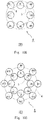
- variations of the arrangement of the antenna elements A1 to AN include, in addition to the antenna elements A1 to AN being arranged on the circumference 3, the antenna elements A1 to AN being evenly arranged on a circumference 4 that is concentric with the circumference 3.
- Another arrangement of the signal radiating means A is, for example, a single circular ring in which eight antenna elements A1 to A8 are arranged on the circumference 3 (see Fig. 10A ).
- Another arrangement of the signal radiating means A is a single rectangular ring in which the eight antenna elements A1 to A8 are arranged on the circumference 3 and the circumference 4 (see Fig. 10B ).
- the signal radiating means A arranged in the single ring is supplied with power in 8 modes by, for example, an 8 ⁇ 8 Butler matrix circuit.
- Another arrangement of the signal radiating means A is a double circular ring in which 16 antenna elements A1 to A16 are arranged on the circumference 3 and the circumference 4 (see Figs. 10C and 10D ).
- the signal radiating means A arranged in the form of a double ring is supplied with power in 8 modes, for example, by a 16 ⁇ 16 Butler matrix circuit.
- the distance between the antenna elements A1 to AN can be narrowed to the level of a wavelength. This prevents the signals radiated from the respective antenna elements A1 to AN from interfering with each other to generate a grating. Consequently, the helical beam H formed by the antenna elements A1 to AN is prevented from degrading by the arrangement of the antenna elements A1 to AN.
- the distance between the antenna elements A1 to AN is narrowed, and thus the apparatus can be downsized to the level of a wavelength.
- the diameter of the parabolic mirror part 15, which is the second wave source may be increased. This eliminates the need to increase the size of the device configuration of the primary radiator 11.
- the device configuration of the radio transmitting antenna 10 can be simplified when the electromagnetic field distribution is expanded in the beam width direction of the helical beam L. This also applies to the radio transmitting antennas 60, 70, 80, and 90.
- the first signal S input to any one of the signal input ports C1 to CM is distributed by the signal distribution circuit B to the N second signals G1 to GN having equal power (S100).
- the signal distribution circuit B gives the phase difference that increases in a stepwise manner to each of the N second signals G1 to GN to be output (S101).
- the signal distribution circuit B distributes the N second signals G1 to GN to the N antenna elements A1 to AN so that the helical beam H whose equiphase surface inclines in a helical manner is formed from the signal radiating means A (S102).
- the primary radiator 11 forms the helical beam (the first helical beam) H and outputs the helical beam H (S103).
- the parabolic mirror part (the second wave source) 15 collects the helical beam H, forms the helical beam (the second helical beam) L output in the constant direction, and transmits the helical beam L (S104).
- the radio transmitting antenna 10 can form the signals output from the respective antenna elements A1 to AN into the helical beam H whose equiphase surface inclines in a helical manner.
- the radio transmitting antenna 10 can freely change the helical rotation pitch of the helical beam H when forming the signals into the helical beam H.
- the radio transmitting antenna 10 can expand the output helical beam H by the parabolic mirror surface part 15 and transmits it in the constant direction.
- the distance between the antenna elements A1 to AN of the primary radiator 11 is narrowed to the level of a wavelength. This prevents a grating from occurring and the helical beam H from degrading. In this way, the radio transmitting antenna 10 can downsize the primary radiator 11 to the level of a wavelength and simplify the device configuration.
- the primary radiator 11 of the radio transmitting antenna 10 forms the signals output from the respective antenna elements A1 to AN into the helical beam whose equiphase surface inclines in a helical manner having a helical rotation pitch corresponding to the signal input ports C1 to CM.
- a plurality of helical beams having different helical rotation pitches are formed using the radio transmitting antenna 10 to perform multiplexed communication.
- the signal distribution circuit B of the radio transmitting antenna 10 includes a plurality of signal input ports C1 to CM and a plurality of signal radiation ports B1 to BN.
- the first signals S1 to SM are input to any of the signal input ports C1 to CM, phase differences having different linear slopes are given to the N second signals G1 to GN, and the N second signals having equal power are output from the signal radiation ports B1 to BN, respectively (see Fig. 9 ).
- the input first signals S are formed into M helical beams H1 to HM having different helical rotation pitches corresponding to the signal input ports C1 to CM, respectively.
- the radio transmitting antenna 10 can simultaneously multiplex and transmit the plurality of helical beams H1 to HM.
- the signal distribution circuit B distributes the M different first signals S1 to SM input to the respective signal input ports C1 to CM into the N second signals G1 to GN having equal power and corresponding to the signal input ports C1 to CM and then outputs the N second signals G1 to GN (S200).
- the signal distribution circuit B gives different phase differences that increase in a stepwise manner to the N distributed second signals G1 to GN and outputs the N second signals G1 to GN from the signal radiation ports B1 to BN (S201).
- the signal distribution circuit B distributes the second signals G1 to GN to the respective N antenna elements A1 to AN so that the M different helical beams H whose equiphase surfaces incline in a helical manner are formed from the signal radiating means A (S202). Then, the M different helical beams (the first helical beams) H are formed and output from the primary radiator 11 (the first wave source) (S203).
- the parabolic mirror part (the second wave source) 15 collects the M different helical beams H, forms the different M helical beams (the second helical beams) L output in the constant direction, and transmits the M helical beams L (S204).
- the radio transmitting antenna 10 can simultaneously multiplex and transmit the plurality of helical beams H1 to HM.
- An antenna having the same configuration as that of the above-described radio transmitting antennas 10, 60, 70, 80, 90 can also be used for receiving antennas of the radio transmitting antennas 10, 60, 70, 80, 90.
- the same combinations of the antennas may be used for the transmission and reception, or different combinations of the antennas may be used for the transmission and reception.
- the receiving antenna performs reception processing by performing a reverse operation of the processing performed by the transmitting antenna for transmitting the helical beam L.
- the radio receiving antenna 20 having the same configuration as that of the radio transmitting antenna 10 will be described as an example.
- the radio receiving antenna 20 includes a parabolic mirror part 25 and first receiving means 21.
- the parabolic mirror part 25 is second receiving means for receiving a helical beam (the second helical beam) L for OAM (Orbital Angular Momentum) output in a constant direction and forms the helical beam (the first helical beam) H.
- the first receiving means 21 receives a helical beam H from the parabolic mirror part 25. That is, in the radio receiving antenna 20, the transmitted helical beam L is received and reflected by the parabolic mirror part unit 25.
- An outer diameter of the parabolic mirror part 25 may differ from an outer diameter of the parabolic mirror part 15 of the radio transmitting antenna 10.
- the outer diameter of the parabolic mirror part 25 may be larger than the outer diameter of the parabolic mirror part 15 of the radio transmitting antenna 10.
- the reflected helical beam L is formed into the helical beam (the first helical beam) H and output.
- the parabolic mirror part 25 receives the helical beam L and forms a helical beam (a third helical beam) H' having a third electromagnetic field distribution that is a reduced second electromagnetic field distribution of the helical beam L.
- the helical beam H' corresponds to the helical beam (the first helical beam) H formed by the primary radiator 11 of the radio transmitting antenna 10.
- the parabolic mirror part 25 receives the helical beam L and forms the helical beam H having the third electromagnetic field distribution concentrated in a small area near a focal point of the parabolic mirror part 25. Then, the helical beam H' is received by the first receiving means 21.
- the first receiving means 21 includes signal receiving means K, which is a reception unit for the helical beam H', and a signal combining circuit (signal combining means) T for combining signals received by the signal receiving means K.
- the first receiving means 21 has the same configuration as that of the primary radiator 11.
- the first receiving means 21 includes the signal receiving means K, the signal combining circuit (signal combining means) T, and signal output means R.
- the signal receiving means K includes X (X is an integer of two or greater) antenna elements K1 to KX evenly arranged on a circumference 3.
- the signal combining circuit T combines X second signals P1 to PX having equal power received from the respective antenna elements K1 to KX into a first signal Q.
- the signal output means R includes Y (positive integer Y ⁇ X) signal output ports R1 to RY that output the first signal Q.
- the first receiving means 21 outputs the received helical beam H' as the first signal Q from the signal output ports R1 to RY.
- the number X of the antenna elements K1 to KX may be greater than the number N of the antenna elements A1 to AN of the primary radiator 11.
- the antenna elements K1 to KX are evenly arranged on the circumference.
- the arranged plurality of antenna elements K1 to KX constitute the signal receiving means K.
- the same antenna element as the antenna element AN may be used as the antenna elements K1 to KX.
- the signal receiving means K and the signal combining circuit T are connected by a signal waveguide U.
- the signal waveguide U includes X equal length signal lines U1 to UX.
- the signal lines U1 to UX connect X signal input ports V1 to VX included in the signal combining circuit T to the antenna elements K1 to KX, respectively.
- an antenna element K0 for receiving signals in a normal mode (non-OAM mode), which is not the OAM mode, may be provided at the center of the signal receiving means K. That is, the signal receiving means K may further include the antenna element K0 that receives signals in the non-OAM mode.
- a coaxial cable or a waveguide can be used as the signal lines U1 to UX.
- the antenna elements K1 to KX may be arranged evenly on a circumference concentric with a circumference 5 in addition to the ones arranged on the circumference 3 (see Figs. 10A to 10D ).
- a diameter of the circumference 5 may differ from a diameter of the circumference 3 in the primary radiator 11.
- the signal combining circuit T combines the second signals P1 to PX having equal power input from the plurality of signal input ports V1 to VX and outputs the combined signal from any one of the signal output ports R1 to RY as the first signal Q according to the helical rotation pitch included in the helical beam H'.
- a Butler matrix feeder circuit can be used as the signal combining circuit T.
- the signal combining circuit T has the same configuration as that of the signal distribution circuit B included in the primary radiator 11 (see Fig. 12 ).
- the radio receiving antenna 20 can output the helical beam H' as the first signal Q by a reverse operation of the operation of the radio transmitting antenna 10.
- the signal combining circuit T receives the helical beam whose equiphase surface inclines in a helical manner, which has been received by the signal receiving means K including X antenna elements K1 to KX arranged at equal intervals on the circumference 5, as the X second signals P1 to PX from the N respective antenna elements K1 to KX, gives a phase difference to each of the X second signals P1 to PX, combines the X second signals P1 to PX, and outputs the first signal Q. Then, the signal combining circuit T gives a predetermined phase difference that decreases in a stepwise manner in the circumferential direction to the X second signals P1 to PX input from the adjacent antenna elements arranged in the signal receiving means K.
- any element may be used as the signal combining circuit T as long as it can receive the helical beam H' from each of the antenna elements K1 to KX arranged at equal intervals on the circumference and output the signal Q.
- the phase differences given to the second signals P1 to PX are not necessarily equally spaced intervals.
- the radio receiving antenna 20 receives the helical beam L by the parabolic mirror surface part 25, which is the second receiving means, forms the helical beam (the first helical beam) H', and outputs the helical beam H' (300).
- the first receiving means 21 sequentially receives the second signals P1 to PX in the fixed rotation direction from the respective X antenna elements K1 to KX evenly arranged on the circumference 5 (S301).
- the signal combining circuit T gives the phase difference decreasing in a stepwise manner to each of the second signals P1 to PX and combines the second signals P1 to PX (S302).
- the signal combining circuit T outputs the first signal Q from any one of the signal output ports R1 to RY (S303).
- the radio receiving antenna 20 can output the received helical beam L as the first signal Q.
- the distance between the antenna elements K1 to KX is narrowed, and the device can be downsized to the level of a wavelength.
- the diameter of the parabolic mirror part 25 may be increased, and it is not necessary to increase the size of the device configuration of the first receiving means 21.
- the ring array antenna described in Patent Literature 1 can receive only signals of a specific mode defined by the diameter of the ring array, whereas the radio receiving antenna 20 can receive all signals of the modes less than or equal to an aperture diameter of the parabolic mirror part 25. Further, the ring array antenna described in Patent Literature 1 can receive signals at a specific distance, whereas the radio receiving antenna 20 can receive signals anywhere as long as the distance is equal to or less than a maximum distance determined by the aperture diameter. Furthermore, the radio receiving antenna 20 receives signals on the surface of the parabolic mirror part 25, and thus it can efficiently receive signals of a plurality of modes having different energy distributions.
- the radio receiving antenna 20 can enhance the reception sensitivity of the helical beam L with a simplified device configuration. This also applies to the case when an antenna having the same configuration as that of the radio transmitting antennas 60, 70, 80, and 90 is used as the reception antenna.
- the radio receiving antenna 20 can receive Y helical beams H having different helical rotation pitches multiplexed and transmitted by the radio transmitting antenna 10 in the second embodiment and outputs them as Y first signals Q.
- the same elements as those of other embodiments are denoted by the same reference terms and signs, and repeated descriptions will be omitted as appropriate.
- the first receiving means 21 includes a signal combining circuit T.
- the signal combining circuit T includes a plurality of signal input ports V1 to VX and a plurality of signal output ports R1 to RY.
- the signal combining circuit T has the same configuration as that of the signal distribution circuit B of the second embodiment.
- the signal combining circuit T when the signal combining circuit T receives the Y helical beams having different helical rotation pitches through the reverse operation of the operation of the signal distribution circuit B, the signal combining circuit T gives the linear phase difference having a slope opposite to the slope corresponding to the signal output ports R1 to RY to each of the received X second signals P1 to PX, combines the second signals P1 to PX, and outputs the Y first signals Q from the signal output ports R1 to RY, respectively.
- the radio receiving antenna 20 receives the Y different helical beams (the second helical beams) L by the parabolic mirror part (a second receiving unit) 25, forms the Y helical beams (the first helical beams) H, and outputs them (S400).
- the first receiving means 21 receives the second signals P1 to PX from the X antenna elements K1 to KX evenly arranged on the circumference in a fixed rotation direction (S401).
- the signal combining circuit T gives the phase difference decreasing in a stepwise manner to each of the second signals P1 to PX and combines the second signals P1 to PX (S402).
- the signal combining circuit T outputs the Y different first signals Q from the signal output ports R1 to RY (S403).
- the radio receiving antenna 20 can receive the Y helical beams L having different helical rotation pitches multiplexed and transmitted by the radio transmitting antenna 10 and outputs them as the Y first signals Q.
- the above-described radio transmitting antenna 10 and the radio receiving antenna 20 can constitute a radio transceiver system 100 that performs radio transmission and reception using the helical beam L. Any one of the radio transmitting antennas 10, 60, 70, 80, 90 may be used for the transmission. An antenna having the same configuration as that of the radio transmitting antennas 10, 60, 70, 80, and 90 can also be used as the reception antenna. The same combinations of the antennas may be used for the transmission and reception, or different combinations of the antennas may be used for the transmission and reception.
- the radio transceiver system 100 includes the radio transmitting antenna 10 and the radio receiving antenna 20.
- the radio transceiver system 100 can transmit and receive signals including the Y helical beams H having multiplexed different helical rotation pitches.
- Fig. 21 shows a primary radiator 31, which is a modified example of the primary radiator 11.
- the primary radiator 31 includes M additional signal input ports Z1 to ZN and another signal distribution circuit E.
- M different first signals W orthogonal to first signals S for forming a helical beam J which is an orthogonal polarization of the helical beam H transmitted by the radio transmission antenna 10 are input.
- the signal distribution circuit E receives the first signals W and outputs N second signals F1 to FN that are orthogonal to second signals G1 to GN.
- a radio transmitting antenna 30 can transmit a helical beam I having a VH polarization.
- a radio receiving antenna (not shown) having the same configuration as that of the radio transmitting antenna 30 can receive the helical beam I having the VH polarization and output the M first signals and other M first signals.
- the present invention has been described as a hardware configuration, but the present invention is not limited to this.
- the present invention can also be realized by performing predetermined processing by DSP (Digital Signal Processing), by executing a program on a DSP (Digital Signal Processor), or by executing a program by a logical circuit composed on an FPGA (Field Programmable Gate Array) or an ASIC (Application Specific Integrated Circuit).
- DSP Digital Signal Processing
- FPGA Field Programmable Gate Array
- ASIC Application Specific Integrated Circuit
- Non-transitory computer readable media include any type of tangible storage media.
- Examples of non-transitory computer readable media include magnetic storage media (such as floppy disks, magnetic tapes, hard disk drives, etc.), optical magnetic storage media (e.g., magneto-optical disks), CD-ROM (Read Only Memory), CD-R, CD-R/W, and semiconductor memories (such as mask ROM, PROM (Programmable ROM), EPROM (Erasable PROM), flash ROM, RAM (Random Access Memory), etc.
- the program may be provided to a computer using any type of transitory computer readable media.
- Transitory computer readable media examples include electric signals, optical signals, and electromagnetic waves.
- Transitory computer readable media can provide the program to a computer via a wired communication line (e.g., electric wires, and optical fibers) or a wireless communication line.
- an 8 ⁇ 8 FFT (Fast Fourier Transform) circuit may be used as the signal distribution circuit B and the signal combining circuit T when digital demultiplexing or demodulating modes with BB (see Figs. 22 and 23 ).
Landscapes
- Physics & Mathematics (AREA)
- Electromagnetism (AREA)
- Variable-Direction Aerials And Aerial Arrays (AREA)
- Aerials With Secondary Devices (AREA)
Abstract
Description
- The present invention relates to a radio signal transmitting antenna, a radio signal receiving antenna, a radio signal transmitting system, a radio signal transmitting method, and a radio signal receiving method that form a signal into a helical beam to perform radio communication.
- Currently, communication in the frequency band used for radio communication is coming close to reaching a limit. In order to solve this problem, a communication technique has been studied in which Orbital Angular Momentum (OAM) is given to a radio signal, and the signal is formed into a helical beam for transmission and reception. The signal from which the helical beam is formed has a feature that the equiphase surface rotates in a helical manner. A change in a helical rotation pitch of the equiphase surface included in the helical beam enables a signal in an infinite orthogonal mode to be formed. Thus, when a helical beam is used for radio communication, a plurality of communications can be established at the same frequency, and communication can be performed at a high speed and with a large capacity.
- Examples of documents relating to an antenna using signals for a helical beam provided with orbital angular momentum include
Patent Literature 1 to 3.Patent Literature 1 discloses an antenna for OAM including N (N is an integer of two or greater) antenna elements arranged at equal intervals on a concentric circle. The antenna for OAM outputs signals radiated from the antenna elements with a phase difference and forms a helical beam to which an orbital angular momentum is given.Patent Literature 2 discloses an antenna device including a wave source that outputs a signal having linear polarization or circular polarization and an OAM filter that forms a signal output from the wave source into a helical beam to which an orbital angular momentum is given.Patent Literature 3 discloses a transmitting antenna including a plurality of first wave sources that transmit a plurality of helical beams having orbital angular momentum in a plurality of modes and a parabolic second wave source that reflects the plurality of helical beams. -
- Patent Literature 1: International Patent Publication No.
WO2012/084039 - Patent Literature 2: Japanese Unexamined Patent Application Publication No.
2015-27042 - Patent Literature 3: International Patent Publication No.
WO2014/199451 - According to the OAM antenna described in
Patent Literature 1, the helical beam is formed using the signals radiated from the plurality of signal elements when the helical beam is formed and the signal is transmitted. In order to transmit the helical beam far away, it is necessary to expand the electromagnetic field distribution in the beam width direction for transmission. Therefore, to form signals for a helical beam in which the electromagnetic field distribution is expanded in the beam width direction, N signal elements need to be arranged on a circumference having a radius larger than that of an existing circumference. However, by doing so, the signals radiated from the respective signal elements interfere with each other to generate a grating, thereby degrading the helical beam to be formed. In order to reduce the degradation of the helical beam, it is necessary to arrange N or more additional signal elements on this circumference so that the distance between the signal elements becomes narrower, resulting in an increase in size and complexity of the configuration. - According to the antenna device for OAM described in
Patent Literature 2, it is necessary to include a plurality of OAM filters corresponding to the respective modes in order to form helical beams of different modes. This complicates the device configuration when the helical beams of the plurality of modes are transmitted. According to the transmitting antenna for OAM described inPatent Literature 3, a plurality of first wave sources corresponding to the respective modes need to be included in order to form helical beams of different modes. This complicates the device configuration when the helical beams of the plurality of modes are transmitted. - An object of the present invention is to provide a radio signal transmitting antenna, a radio signal receiving antenna, a radio signal transmitting system, a radio signal transmitting method, and a radio signal receiving method for OAM that are capable of transmitting or receiving a helical beam with a simplified and smaller device configuration in an antenna for OAM that forms a signal into a helical beam.
- A radio signal transmitting antenna according to the present invention includes:
- a first wave source including a plurality of antenna elements configured to form a first helical beam for OAM (Orbital Angular Momentum) from the plurality of antenna elements and output the first helical beam; and
- a second wave source configured to receive the first helical beam and form a second helical beam output in a constant direction and transmits the second helical beam.
- A radio signal transmitting antenna according to the present invention includes:
- a first wave source including a plurality of antenna elements configured to form a first helical beam for OAM (Orbital Angular Momentum) from the plurality of antenna elements and output the first helical beam; and
- a second wave source configured to receive the first helical beam and form a second helical beam including a second electromagnetic field distribution, the second electromagnetic field distribution being an expanded first electromagnetic field distribution included in the first helical beam.
- A radio signal receiving antenna according to the present invention includes:
- second receiving means for receiving a second helical beam for OAM (Orbital Angular Momentum) and converting the second helical beam into a third helical beam including a third electromagnetic field distribution to concentrate power, the third electromagnetic field distribution being a reduced second electromagnetic field distribution included in the second helical beam; and
- first receiving means including a plurality of antenna elements for receiving the third helical beam from the plurality of antenna elements.
- A radio signal transceiver system according to the present invention includes:
- a radio signal transmitting antenna including:
- a first wave source including a plurality of antenna elements configured to form a first helical beam for OAM (Orbital Angular Momentum) from the plurality of antenna elements and output the helical beam; and
- a second wave source configured to receive the first helical beam and form a second helical beam including a second electromagnetic field distribution, the second electromagnetic field distribution being an expanded first electromagnetic field distribution included in the first helical beam;
- a radio signal receiving antenna including:
- second receiving means for receiving the second helical beam and converting the second helical beam into a third helical beam including a third electromagnetic field distribution to concentrate power, the third electromagnetic field distribution being the reduced second electromagnetic field distribution; and
- first receiving means including a plurality of antenna elements for receiving the third helical beam from the plurality of antenna elements.
- A radio signal transmitting method according to the present invention includes:
- forming a first helical beam for OAM (Orbital Angular Momentum) from a plurality of antenna elements and outputting the first helical beam; and
- receiving the first helical beam and forming a second helical beam including a second electromagnetic field distribution, the second electromagnetic field distribution being an expanded first electromagnetic field distribution included in the first helical beam.
- A radio signal receiving method according to the present invention includes:
- receiving a second helical beam for OAM (Orbital Angular Momentum) and converting the second helical beam into a third helical beam including a third electromagnetic field distribution to concentrate power, the third electromagnetic field distribution being the reduced second electromagnetic field distribution; and
- receiving the third helical beam from a plurality of antenna elements.
- According to the radio signal transmitting antenna, the radio signal receiving antenna, the radio signal transmitting system, the radio signal transmitting method, and the radio signal receiving method of the present invention, it is possible to transmit or receive a helical beam for OAM with a simplified and smaller device configuration.
-
-
Fig. 1 is a diagram showing a configuration of a radio transmitting antenna according to a first embodiment of the present invention; -
Fig. 2 is a diagram showing a configuration of a radio transmitting antenna according to a second embodiment of the present invention; -
Fig. 3 is a diagram showing a configuration of a radio transmitting antenna according to a third embodiment of the present invention; -
Fig. 4 is a diagram showing a configuration of a radio transmitting antenna according to a fourth embodiment of the present invention; -
Fig. 5 is a diagram showing a configuration of a radio transmitting antenna according to a fifth embodiment of the present invention; -
Fig. 6 is a block diagram showing a configuration of a primary radiator included in a radio transmitting antenna; -
Fig. 7 is a diagram showing a principle of a signal distribution circuit using a Butler matrix feeder circuit; -
Fig. 8 is a diagram showing a state in which a helical beam is formed from signal radiating means A; -
Fig. 9 is a diagram showing a principle of a signal distribution circuit using a Butler matrix feeder circuit having a plurality of input ports; -
Fig. 10A is a diagram showing another arrangement of a plurality of antenna elements; -
Fig. 10B is a diagram showing another arrangement of a plurality of antenna elements; -
Fig. 10C is a diagram showing another arrangement of a plurality of antenna elements; -
Fig. 10D is a diagram showing another arrangement of a plurality of antenna elements; -
Fig. 11 is a flowchart showing a process in which a radio transmitting antenna forms a helical beam; -
Fig. 12 is a diagram showing a configuration of a signal distribution circuit included in a radio transmitting antenna according to a sixth embodiment. -
Fig. 13 is a diagram showing a state in which M different first signals are input to a radio transmitting antenna. -
Fig. 14 is a flowchart showing a process of forming M different helical beams from a radio transmitting antenna. -
Fig. 15 is a diagram showing a configuration of a radio receiving antenna according to a seventh embodiment of the present invention. -
Fig. 16 is a block diagram showing a configuration of a primary radiator included in a radio transmitting antenna. -
Fig. 17 is a flowchart showing a process in which a radio receiving antenna receives a helical beam. -
Fig. 18 is a diagram showing a configuration of a signal combining circuit included in a radio receiving antenna. -
Fig. 19 is a flowchart showing a process in which the radio receiving antenna receives M different helical beams. -
Fig. 20 is a diagram showing a configuration of a radio transceiver system according to an eighth embodiment of the present invention. -
Fig. 21 is a block diagram showing a configuration of a primary radiator according to a tenth embodiment of the present invention. -
Fig. 22 shows a modified example using an FFT circuit for a signal distribution circuit; and -
Fig. 23 shows a modified example using an FFT circuit for a signal combining circuit. - Hereinafter, embodiments of the present invention will be described with reference to the drawings.
- As shown in
Fig. 1 , aradio transmitting antenna 10 includes a primary radiator (a first wave source) that forms and outputs a helical beam (a first helical beam) H for OAM (Orbital Angular Momentum) 11, and a parabolic mirror part (first reflecting means or a second wave source) 15 that collects the output helical beam H to form a helical beam (a second helical beam) L and outputs it in a constant direction. That is, in theradio transmitting antenna 10, the helical beam H output from theprimary radiator 11 is reflected by theparabolic mirror part 15 and then transmitted in a constant direction as the helical beam L. - The
parabolic mirror part 15 is a bowl-shaped radio wave reflecting part including aparabolic surface 16 formed on a front surface. Theparabolic mirror part 15 is formed of a metal material such as stainless steel or aluminum. Theprimary radiator 11 is disposed on a front side of theparabolic mirror part 15. Theprimary radiator 11 is disposed to irradiate theparabolic mirror part 15 with the helical beam H. Theprimary radiator 11 includes signal radiating means A that radiates the helical beam H and a signal distribution circuit B that distributes signals to the signal radiating means A. Theprimary radiator 11 is disposed on the side of the front surface of theparabolic surface 16 of theparabolic mirror part 15. For example, theprimary radiator 11 is disposed in such a way that the signal radiating means A is at near a position to be a focal point of theparabolic surface 16 of theparabolic mirror part 15. - The
primary radiator 11 is fixed to theparabolic mirror part 15 by, for example, a stay (not shown). The helical beam H radiated from the signal radiating means A is collected (received) by theparabolic surface 16 of theparabolic mirror part 15 and is reflected in the constant direction (a direction of arrows 13). The reflected wave of the helical beam H is formed into the helical beam L, and the helical beam L is output in the direction of thearrows 13. Theparabolic mirror part 15 receives the helical beam H, expands an electromagnetic field distribution included in the helical beam H, forms the helical beam L having a second electromagnetic field distribution that is larger than the first electromagnetic field distribution, and then outputs the helical beam L. - That is, the
radio transmitting antenna 10 can transmit the helical beam L having the expanded electromagnetic field distribution from theparabolic mirror part 15 in the constant direction. According to theradio transmitting antenna 10, the first electromagnetic field distribution of the helical beam H formed by the primary radiator is expanded by theparabolic mirror part 15 as the second electromagnetic field distribution. The second electromagnetic field distribution is wider than the first electromagnetic field distribution in a beam width direction with respect to a direction in which the helical beam H travels. Thus, the size of theprimary radiator 11 can be reduced. - As shown in
Fig. 2 , aradio transmitting antenna 60, which is a modified example of theradio transmitting antenna 10, will be described. In this embodiment, the same components as those of theradio transmitting antenna 10 are denoted by the same reference terms and signs, the components having functions similar to those of theradio transmitting antenna 10 are denoted by the same reference terms, and repeated descriptions will be omitted as appropriate. This applies to the following embodiments. - The
radio transmitting antenna 60 includes aprimary radiator 11 that forms and outputs a helical beam H, a sub-reflecting mirror part (second reflecting means) 63 that reflects the output helical beam H, and a parabolic mirror part (first reflecting means or a second wave source) 65 that collects the reflected helical beam H, forms a helical beam L, and outputs the helical beam L in a constant direction. That is, in theradio transmitting antenna 60, the helical beam H output from theprimary radiator 11 is indirectly reflected by thesub-reflecting mirror part 63 and then reflected by theparabolic mirror part 65 to be formed into the helical beam L. Then, the helical beam L is output in the constant direction. - The
parabolic mirror part 65 is a bowl-shaped radio wave reflecting part including aparabolic surface 66 formed on a front surface. Thesub-reflecting mirror part 63 is disposed to face theparabolic mirror part 65 on a front side thereof. Theprimary radiator 11 is disposed between theparabolic mirror part 65 and thesub-reflecting mirror part 63. Thesub-reflecting mirror part 63 is a bowl-shaped radio wave reflecting part including ahyperboloid surface 64. Thesub-reflecting mirror part 63 is disposed in such a way that a convex part of thehyperboloid surface 64 faces theparabolic surface 66. Theprimary radiator 11 is disposed in such a way that thesub-reflecting mirror part 63 is irradiated with the helical beam H. That is, theradio transmitting antenna 60 has a shape of a Cassegrain antenna. - The helical beam H radiated from the
primary radiator 11 is reflected to be diffused by thesub-reflecting mirror part 63. The reflected wave is output as a helical beam H1. The helical beam H1 is collected by theparabolic mirror part 65 and is reflected in a constant direction (a direction of arrows 67). Theprimary radiator 11 and thesub-reflecting mirror part 63 are arranged in such a positional relationship that the helical beam H1 is radiated from a focal point of theparabolic surface 66. According to theradio transmitting antenna 60, when the size of theparabolic mirror part 65 is increased, a length of a waveguide (not shown) connected to theprimary radiator 11 can be reduced, thereby reducing a transmission loss. - As shown in
Fig. 3 , aradio transmitting antenna 70 may have a configuration including asub-reflecting mirror part 63B in which arotation ellipsoid surface 64B is formed in place of thesub-reflecting mirror part 63 of theradio transmitting antenna 60. Thesub-reflecting mirror part 63B is disposed in such a way that a concave part of therotation ellipsoid surface 64B faces aparabolic surface 66. That is, theradio transmitting antenna 70 has a shape of a Gregorian antenna. According to theradio transmitting antenna 70, when the size of theparabolic mirror part 65 is increased, a length of a waveguide (not shown) connected to theprimary radiator 11 can be reduced, thereby reducing a transmission loss. - As shown in
Fig. 4 , in aradio transmitting antenna 80, a parabolic mirror part (first reflecting means or a second wave source) 85 is disposed in such a way that aparabolic surface 86 is offset from theprimary radiator 11. That is, theradio transmitting antenna 80 has a shape of an offset antenna. According to theradio transmitting antenna 80, aprimary radiator 11 disposed at a focal position with respect to theparabolic mirror part 85 will not become an obstacle, and a mounting angle of theparabolic mirror part 85 to a ground surface (not shown) becomes steep. This achieves an effect that hardly any foreign objects, snow, etc. pile up on theparabolic mirror part 85. - As shown in
Fig. 5 , aradio transmitting antenna 90 includes a primary radiator (a first wave source) 11 that forms and outputs a helical beam H for OAM and a lens surface part (first reflecting means or a second wave source) 95 that collects the output helical beam H to form a helical beam (a second helical beam) L and output it in a constant direction. That is, in theradio transmitting antenna 10, the helical beam H output from theprimary radiator 11 is reflected by thelens surface part 95, formed into a helical beam L, and transmitted in a constant direction. - The
lens surface part 95 is a radio wave refracting part whose entire surface is formed into a convex lens shape. Thelens surface part 95 is molded using, for example, a lens medium that transmits radio waves. Theprimary radiator 11 is disposed on a rear side of thelens surface part 95. Theprimary radiator 11 is disposed to irradiate a rear part of thelens surface part 95 with the helical beam H. Theprimary radiator 11 is disposed in such a way that the signal radiating means A is at a focal point of thelens surface part 95. Theprimary radiator 11 is fixed to thelens surface part 95 by, for example, a stay (not shown). - The helical beam H radiated from the signal radiating means A is collected by the
lens surface part 95 and is refracted in a constant direction (a direction of arrows 93). The refracted wave of the helical beam H is formed into a parallel helical beam L, and the helical beam L is output in the direction of thearrows 93. That is, theradio transmitting antenna 10 can transmit the parallel helical beam L from thelens surface part 95 in the constant direction. According to theradio transmitting antenna 90, the electromagnetic field distribution of the helical beam H radiated from the primary radiator is expanded by thelens surface part 95 in a beam width direction with respect to a direction in which the helical beam H travels. Thus, the size of theprimary radiator 11 can be reduced. - Next, the
primary radiator 11 common to the first to fifth embodiments will be described in detail. - As shown in
Fig. 6 , theprimary radiator 11 includes the signal radiating means A including N (N is an integer of two or greater) antenna elements A1, A2 to AN evenly arranged on a circumference, a signal input port (signal input means) C that inputs M (M is a positive integer) first signals S1 to SM, and a signal distribution circuit (signal distribution means) B that distributes the input M first signals S1 to SM to N second signals S2 having equal power and outputs the second signals S2 to the antenna elements A1, A2 to AN, respectively. With such a configuration, theradio transmitting antenna 10 forms the helical beam H from the input M first signals S1 to SM and outputs the helical beam H from the antenna elements A1, A2 to AN. - The antenna elements A1 to AN are evenly arranged on a circumference 3 (a ring array). A radius of the
circumference 3 is about one wavelength of the signal to be transmitted. The plurality of the antenna elements A1 to AN constitute the signal radiating means A. Any element may be used as the antenna elements A1 to AN as long as it can radiate a signal. The signal radiating means A is connected to the signal distribution circuit B by a signal waveguide D. The signal waveguide D includes N equal length signal lines D1 to DN. The signal lines D1 to DN connect N signal radiation ports B1 to BN included in the signal distribution circuit B to the antenna elements A1 to AN, respectively. A coaxial cable or a waveguide can be used as the signal lines D1 to DN. - An antenna element A0 radiating signals in a normal mode (non-OAM mode), which is not the OAM mode, may be provided at the center of the signal radiating means A. That is, the signal radiating means A may further include the antenna element A0 that outputs signals in the non-OAM mode. The antenna element A0 may be disposed at a position other than the center of the signal radiating means A. A waveguide branched from any one of the signal radiation ports B1 to BN may be connected to the antenna element A0, or a circuit for other signals that outputs signals in the normal mode may be connected to the antenna element A0.
- The signal distribution circuit B distributes the first signal S input from some of the M signal input ports C1 to CM to N second signals G1 to GN having equal power and radiates the second signals G1 to GN from the signal radiation ports B1 to BN, respectively. For example, a Butler matrix feeder circuit can be used as the signal distribution circuit B. The Butler matrix is commonly used for changing the direction of transmitting beams. The Butler matrix is used for analog multiplexing or demultiplexing RF (Radio Frequency) or IF (Intermediate Frequency) mode.
- As shown in
Fig. 7 , according to the signal distribution circuit B using the Butler matrix feeder circuit, when the first signal S1 is input from the signal input port C1, the N second signals G1 to GN having equal power are distributed and output from the signal radiation ports B1 to BN, respectively. At this time, the signal distribution circuit B gives a phase difference having a linear slope θ1 to each of the N second signals G1 to GN radiated from the signal radiation ports B1 to BN, respectively. The helical beam H is formed using this property. Specifically, the equal length signal lines D1 to DN are connected to the antenna elements A1 to AN from the signal radiation ports B1 to BN (seeFig. 6 ), respectively. Further, the antenna elements A1 to AN are evenly arranged on the circumference 3 (seeFig. 6 ). - As shown in
Fig. 8 , when the second signals G1 to GN are sequentially radiated from the respective antenna elements A1 to AN at predetermined intervals in a fixed rotation direction (clockwise or counterclockwise), the helical beam H is formed from the signal radiating means A. The rotation direction of the helical beam is changed according to the connection between the antenna elements A1 to AN and the signal lines D1 to DN. In the OAM mode in which the helical beam H is formed, there may be a case where N=2. In the case of N=2, the rotation direction may be regarded as being either clockwise or counterclockwise. The rotation direction of the helical beam H can be determined when N is three or greater. - As shown in
Fig. 9 , the Butler matrix commonly includes a plurality of signal input ports C1 to CM (positive integer M≤N). To change the slope θN of the phase difference that linearly inclines and appears at the signal radiation ports B1 to BN, the signal input ports C1 to CM for inputting the first signals S1 to SM are changed. For example, the first signal S2 input to the signal input port C2 is output as the second signals G1 to GN provided with a phase difference of a linear slope θ2. Using this property, the helical rotation pitch of the helical beam H can be changed to correspond to the signal input ports C1 to CM. Specifically, the signal output from the signal radiating means A can be formed into the helical beam H having the helical rotation pitch corresponding to the signal input ports C1 to CM whose equiphase surface inclines in a helical manner. - That is, the signal distribution circuit B generates, from the input first signal S, the N second signals G1 to GN having phase differences from one another. Then, the signal distribution circuit B outputs the N second signals G1 to GN to the N antenna elements A1 to AN, respectively, so that the helical beam H with a helically inclined equiphase surface is output from the signal radiating means A. At this time, the signal distribution circuit B distributes the signals in such a way that the second signals G1 to GN having a predetermined phase difference that increases in a stepwise manner (with an equal difference) in the circumference direction are input to the antenna elements A1 to AN that are adjacent in the signal radiating means A.
- In the above description, the Butler matrix feeder circuit is used as the signal distribution circuit B. Alternatively, any element may be used as the signal distribution circuit B as long as it can output the second signals G1 to GN in such a way that the helical beam H is formed from the antenna elements A1 to AN that are arranged at equal intervals on a circumference. The phase difference given to the second signals does not necessarily have to be equally spaced (with an equal difference).
- As shown in
Figs. 10A to 10D , variations of the arrangement of the antenna elements A1 to AN include, in addition to the antenna elements A1 to AN being arranged on thecircumference 3, the antenna elements A1 to AN being evenly arranged on acircumference 4 that is concentric with thecircumference 3. Another arrangement of the signal radiating means A is, for example, a single circular ring in which eight antenna elements A1 to A8 are arranged on the circumference 3 (seeFig. 10A ). Another arrangement of the signal radiating means A is a single rectangular ring in which the eight antenna elements A1 to A8 are arranged on thecircumference 3 and the circumference 4 (seeFig. 10B ). The signal radiating means A arranged in the single ring is supplied with power in 8 modes by, for example, an 8×8 Butler matrix circuit. - Another arrangement of the signal radiating means A is a double circular ring in which 16 antenna elements A1 to A16 are arranged on the
circumference 3 and the circumference 4 (seeFigs. 10C and10D ). The signal radiating means A arranged in the form of a double ring is supplied with power in 8 modes, for example, by a 16×16 Butler matrix circuit. - According to this arrangement of the antenna elements A1 to AN, the distance between the antenna elements A1 to AN can be narrowed to the level of a wavelength. This prevents the signals radiated from the respective antenna elements A1 to AN from interfering with each other to generate a grating. Consequently, the helical beam H formed by the antenna elements A1 to AN is prevented from degrading by the arrangement of the antenna elements A1 to AN.
- As described above, in the
primary radiator 11, which is the first wave source, the distance between the antenna elements A1 to AN is narrowed, and thus the apparatus can be downsized to the level of a wavelength. In order to expand the electromagnetic field distribution in the beam width direction of the helical beam L radiated from theradio transmitting antenna 10 in the constant direction, the diameter of theparabolic mirror part 15, which is the second wave source, may be increased. This eliminates the need to increase the size of the device configuration of theprimary radiator 11. Thus, the device configuration of theradio transmitting antenna 10 can be simplified when the electromagnetic field distribution is expanded in the beam width direction of the helical beam L. This also applies to theradio transmitting antennas - Next, the radio transmitting method for transmitting the helical beam L by the
radio transmitting antenna 10 will be briefly described with reference toFig. 11 . - In the
radio transmitting antenna 10, the first signal S input to any one of the signal input ports C1 to CM is distributed by the signal distribution circuit B to the N second signals G1 to GN having equal power (S100). The signal distribution circuit B gives the phase difference that increases in a stepwise manner to each of the N second signals G1 to GN to be output (S101). The signal distribution circuit B distributes the N second signals G1 to GN to the N antenna elements A1 to AN so that the helical beam H whose equiphase surface inclines in a helical manner is formed from the signal radiating means A (S102). Then, the primary radiator 11 (the first wave source) forms the helical beam (the first helical beam) H and outputs the helical beam H (S103). The parabolic mirror part (the second wave source) 15 collects the helical beam H, forms the helical beam (the second helical beam) L output in the constant direction, and transmits the helical beam L (S104). - As described above, the
radio transmitting antenna 10 can form the signals output from the respective antenna elements A1 to AN into the helical beam H whose equiphase surface inclines in a helical manner. Theradio transmitting antenna 10 can freely change the helical rotation pitch of the helical beam H when forming the signals into the helical beam H. Furthermore, theradio transmitting antenna 10 can expand the output helical beam H by the parabolicmirror surface part 15 and transmits it in the constant direction. Moreover, according to theradio transmitting antenna 10, the distance between the antenna elements A1 to AN of theprimary radiator 11 is narrowed to the level of a wavelength. This prevents a grating from occurring and the helical beam H from degrading. In this way, theradio transmitting antenna 10 can downsize theprimary radiator 11 to the level of a wavelength and simplify the device configuration. - In the first embodiment, the
primary radiator 11 of theradio transmitting antenna 10 forms the signals output from the respective antenna elements A1 to AN into the helical beam whose equiphase surface inclines in a helical manner having a helical rotation pitch corresponding to the signal input ports C1 to CM. In this embodiment, a plurality of helical beams having different helical rotation pitches are formed using theradio transmitting antenna 10 to perform multiplexed communication. In the following description, the same elements as those of the first embodiment are denoted by the same reference terms and signs, and repeated descriptions will be omitted as appropriate. - As shown in
Fig. 12 , the signal distribution circuit B of theradio transmitting antenna 10 includes a plurality of signal input ports C1 to CM and a plurality of signal radiation ports B1 to BN.Fig. 12 shows a configuration of the signal distribution circuit B having a Butler matrix feeder circuit with 8 (=M) inputs and 8 (=N) outputs. When the first signals S1 to SM are input to any of the signal input ports C1 to CM, phase differences having different linear slopes are given to the N second signals G1 to GN, and the N second signals having equal power are output from the signal radiation ports B1 to BN, respectively (seeFig. 9 ). Then, the input first signals S are formed into M helical beams H1 to HM having different helical rotation pitches corresponding to the signal input ports C1 to CM, respectively. - As shown in
Fig. 13 , when M different first signals S1 to SM are input to the M signal input ports C1 to CM, respectively, phase differences having different linear slopes θ1 to θN are given to the N second signals G1 to GN having equal power and corresponding to the signal input ports C1 to CM, and then the N second signals G1 to GN having equal power are output from the signal radiation ports B1 to BN, respectively. The second signals G1 to GN corresponding to the signal input ports C1 to CM are sequentially output from the antenna elements A1 to AN at equal intervals and at a predetermined time to thereby simultaneously form the M helical beams H1 to HM having different helical rotation pitches. That is, theradio transmitting antenna 10 can simultaneously multiplex and transmit the plurality of helical beams H1 to HM. - Next, a radio transmitting method for forming a plurality of helical beams H having different helical rotation pitches performed by the
radio transmitting antenna 10 will be described with reference toFig. 14 . - In the
radio transmitting antenna 10, the signal distribution circuit B distributes the M different first signals S1 to SM input to the respective signal input ports C1 to CM into the N second signals G1 to GN having equal power and corresponding to the signal input ports C1 to CM and then outputs the N second signals G1 to GN (S200). The signal distribution circuit B gives different phase differences that increase in a stepwise manner to the N distributed second signals G1 to GN and outputs the N second signals G1 to GN from the signal radiation ports B1 to BN (S201). - The signal distribution circuit B distributes the second signals G1 to GN to the respective N antenna elements A1 to AN so that the M different helical beams H whose equiphase surfaces incline in a helical manner are formed from the signal radiating means A (S202). Then, the M different helical beams (the first helical beams) H are formed and output from the primary radiator 11 (the first wave source) (S203). The parabolic mirror part (the second wave source) 15 collects the M different helical beams H, forms the different M helical beams (the second helical beams) L output in the constant direction, and transmits the M helical beams L (S204).
- As described above, the
radio transmitting antenna 10 can simultaneously multiplex and transmit the plurality of helical beams H1 to HM. - An antenna having the same configuration as that of the above-described
radio transmitting antennas radio transmitting antennas radio receiving antenna 20 having the same configuration as that of theradio transmitting antenna 10 will be described as an example. - As shown in
Fig. 15 , theradio receiving antenna 20 includes aparabolic mirror part 25 and first receiving means 21. Theparabolic mirror part 25 is second receiving means for receiving a helical beam (the second helical beam) L for OAM (Orbital Angular Momentum) output in a constant direction and forms the helical beam (the first helical beam) H. The first receiving means 21 receives a helical beam H from theparabolic mirror part 25. That is, in theradio receiving antenna 20, the transmitted helical beam L is received and reflected by the parabolicmirror part unit 25. An outer diameter of theparabolic mirror part 25 may differ from an outer diameter of theparabolic mirror part 15 of theradio transmitting antenna 10. For example, the outer diameter of theparabolic mirror part 25 may be larger than the outer diameter of theparabolic mirror part 15 of theradio transmitting antenna 10. - The reflected helical beam L is formed into the helical beam (the first helical beam) H and output. The
parabolic mirror part 25 receives the helical beam L and forms a helical beam (a third helical beam) H' having a third electromagnetic field distribution that is a reduced second electromagnetic field distribution of the helical beam L. The helical beam H' corresponds to the helical beam (the first helical beam) H formed by theprimary radiator 11 of theradio transmitting antenna 10. - That is, the
parabolic mirror part 25 receives the helical beam L and forms the helical beam H having the third electromagnetic field distribution concentrated in a small area near a focal point of theparabolic mirror part 25. Then, the helical beam H' is received by the first receiving means 21. The first receiving means 21 includes signal receiving means K, which is a reception unit for the helical beam H', and a signal combining circuit (signal combining means) T for combining signals received by the signal receiving means K. The first receiving means 21 has the same configuration as that of theprimary radiator 11. - As shown in
Fig. 16 , the first receiving means 21 includes the signal receiving means K, the signal combining circuit (signal combining means) T, and signal output means R. The signal receiving means K includes X (X is an integer of two or greater) antenna elements K1 to KX evenly arranged on acircumference 3. The signal combining circuit T combines X second signals P1 to PX having equal power received from the respective antenna elements K1 to KX into a first signal Q. The signal output means R includes Y (positive integer Y≤X) signal output ports R1 to RY that output the first signal Q. With such a configuration, the first receiving means 21 outputs the received helical beam H' as the first signal Q from the signal output ports R1 to RY. The number X of the antenna elements K1 to KX may be greater than the number N of the antenna elements A1 to AN of theprimary radiator 11. - The antenna elements K1 to KX are evenly arranged on the circumference. The arranged plurality of antenna elements K1 to KX constitute the signal receiving means K. The same antenna element as the antenna element AN may be used as the antenna elements K1 to KX. The signal receiving means K and the signal combining circuit T are connected by a signal waveguide U. The signal waveguide U includes X equal length signal lines U1 to UX. The signal lines U1 to UX connect X signal input ports V1 to VX included in the signal combining circuit T to the antenna elements K1 to KX, respectively. Like the signal radiating means A, an antenna element K0 for receiving signals in a normal mode (non-OAM mode), which is not the OAM mode, may be provided at the center of the signal receiving means K. That is, the signal receiving means K may further include the antenna element K0 that receives signals in the non-OAM mode.
- A coaxial cable or a waveguide can be used as the signal lines U1 to UX. Like the plurality of antenna elements A1 to AN, the antenna elements K1 to KX may be arranged evenly on a circumference concentric with a
circumference 5 in addition to the ones arranged on the circumference 3 (seeFigs. 10A to 10D ). In the first receiving means 21, a diameter of thecircumference 5 may differ from a diameter of thecircumference 3 in theprimary radiator 11. - The signal combining circuit T combines the second signals P1 to PX having equal power input from the plurality of signal input ports V1 to VX and outputs the combined signal from any one of the signal output ports R1 to RY as the first signal Q according to the helical rotation pitch included in the helical beam H'. For example, a Butler matrix feeder circuit can be used as the signal combining circuit T. The signal combining circuit T has the same configuration as that of the signal distribution circuit B included in the primary radiator 11 (see
Fig. 12 ). - That is, when the second signals P1 to PX are input to the signal distribution circuit B conversely, the signals are combined into the first signal Q and then output, and the signal distribution circuit B becomes the signal combining circuit T. In other words, the
radio receiving antenna 20 can output the helical beam H' as the first signal Q by a reverse operation of the operation of theradio transmitting antenna 10. - Specifically, the signal combining circuit T receives the helical beam whose equiphase surface inclines in a helical manner, which has been received by the signal receiving means K including X antenna elements K1 to KX arranged at equal intervals on the
circumference 5, as the X second signals P1 to PX from the N respective antenna elements K1 to KX, gives a phase difference to each of the X second signals P1 to PX, combines the X second signals P1 to PX, and outputs the first signal Q. Then, the signal combining circuit T gives a predetermined phase difference that decreases in a stepwise manner in the circumferential direction to the X second signals P1 to PX input from the adjacent antenna elements arranged in the signal receiving means K. - In the above description, an example using a Butler matrix feeder circuit for the signal combining circuit T has been described. However, any element may be used as the signal combining circuit T as long as it can receive the helical beam H' from each of the antenna elements K1 to KX arranged at equal intervals on the circumference and output the signal Q. Moreover, the phase differences given to the second signals P1 to PX are not necessarily equally spaced intervals.
- Next, processing in which the
radio receiving antenna 20 receives the helical beam L will be described with reference toFig. 17 . - When the helical beam L is transmitted from the
radio transmitting antenna 10, theradio receiving antenna 20 receives the helical beam L by the parabolicmirror surface part 25, which is the second receiving means, forms the helical beam (the first helical beam) H', and outputs the helical beam H' (300). The first receiving means 21 sequentially receives the second signals P1 to PX in the fixed rotation direction from the respective X antenna elements K1 to KX evenly arranged on the circumference 5 (S301). - As the phase difference increasing in a stepwise manner is given to the second signals P1 to PX, conversely, the signal combining circuit T gives the phase difference decreasing in a stepwise manner to each of the second signals P1 to PX and combines the second signals P1 to PX (S302). The signal combining circuit T outputs the first signal Q from any one of the signal output ports R1 to RY (S303).
- As described above, the
radio receiving antenna 20 can output the received helical beam L as the first signal Q. In this way, in the first receiving means 21, the distance between the antenna elements K1 to KX is narrowed, and the device can be downsized to the level of a wavelength. In order to enhance the reception sensitivity of the helical beam L transmitted from theradio transmitting antenna 10, the diameter of theparabolic mirror part 25 may be increased, and it is not necessary to increase the size of the device configuration of the first receiving means 21. - For example, the ring array antenna described in
Patent Literature 1 can receive only signals of a specific mode defined by the diameter of the ring array, whereas theradio receiving antenna 20 can receive all signals of the modes less than or equal to an aperture diameter of theparabolic mirror part 25. Further, the ring array antenna described inPatent Literature 1 can receive signals at a specific distance, whereas theradio receiving antenna 20 can receive signals anywhere as long as the distance is equal to or less than a maximum distance determined by the aperture diameter. Furthermore, theradio receiving antenna 20 receives signals on the surface of theparabolic mirror part 25, and thus it can efficiently receive signals of a plurality of modes having different energy distributions. - Therefore, the
radio receiving antenna 20 can enhance the reception sensitivity of the helical beam L with a simplified device configuration. This also applies to the case when an antenna having the same configuration as that of theradio transmitting antennas - The
radio receiving antenna 20 can receive Y helical beams H having different helical rotation pitches multiplexed and transmitted by theradio transmitting antenna 10 in the second embodiment and outputs them as Y first signals Q. In the following description, the same elements as those of other embodiments are denoted by the same reference terms and signs, and repeated descriptions will be omitted as appropriate. - As shown in
Fig. 18 , in theradio receiving antenna 20, the first receiving means 21 includes a signal combining circuit T. The signal combining circuit T includes a plurality of signal input ports V1 to VX and a plurality of signal output ports R1 to RY. InFig. 18 , a configuration of the signal combining circuit T including a Butler matrix feeder circuit of Y=8 and X=8 is shown. The signal combining circuit T has the same configuration as that of the signal distribution circuit B of the second embodiment. That is, when the signal combining circuit T receives the Y helical beams having different helical rotation pitches through the reverse operation of the operation of the signal distribution circuit B, the signal combining circuit T gives the linear phase difference having a slope opposite to the slope corresponding to the signal output ports R1 to RY to each of the received X second signals P1 to PX, combines the second signals P1 to PX, and outputs the Y first signals Q from the signal output ports R1 to RY, respectively. - Next, processing in which the
radio receiving antenna 20 receives signals including Y helical beams H having different helical rotation pitches will be described with reference toFig. 19 . - When the Y helical beams L having different helical rotation pitches are transmitted from the
radio transmitting antenna 10, theradio receiving antenna 20 receives the Y different helical beams (the second helical beams) L by the parabolic mirror part (a second receiving unit) 25, forms the Y helical beams (the first helical beams) H, and outputs them (S400). The first receiving means 21 receives the second signals P1 to PX from the X antenna elements K1 to KX evenly arranged on the circumference in a fixed rotation direction (S401). As the phase difference increasing in a stepwise manner is given to the second signals P1 to PX, conversely to the phase difference increasing in a stepwise manner, the signal combining circuit T gives the phase difference decreasing in a stepwise manner to each of the second signals P1 to PX and combines the second signals P1 to PX (S402). The signal combining circuit T outputs the Y different first signals Q from the signal output ports R1 to RY (S403). - As described above, the
radio receiving antenna 20 can receive the Y helical beams L having different helical rotation pitches multiplexed and transmitted by theradio transmitting antenna 10 and outputs them as the Y first signals Q. - The above-described
radio transmitting antenna 10 and theradio receiving antenna 20 can constitute aradio transceiver system 100 that performs radio transmission and reception using the helical beam L. Any one of theradio transmitting antennas radio transmitting antennas - As shown in
Fig. 20 , theradio transceiver system 100 includes theradio transmitting antenna 10 and theradio receiving antenna 20. Theradio transceiver system 100 can transmit and receive signals including the Y helical beams H having multiplexed different helical rotation pitches. -
Fig. 21 shows aprimary radiator 31, which is a modified example of theprimary radiator 11. Theprimary radiator 31 includes M additional signal input ports Z1 to ZN and another signal distribution circuit E. To the M signal input ports Z1 to ZN, M different first signals W orthogonal to first signals S for forming a helical beam J, which is an orthogonal polarization of the helical beam H transmitted by theradio transmission antenna 10, are input. The signal distribution circuit E receives the first signals W and outputs N second signals F1 to FN that are orthogonal to second signals G1 to GN. - Thus, a radio transmitting antenna 30 can transmit a helical beam I having a VH polarization. A radio receiving antenna (not shown) having the same configuration as that of the radio transmitting antenna 30 can receive the helical beam I having the VH polarization and output the M first signals and other M first signals.
- In the above embodiments, the present invention has been described as a hardware configuration, but the present invention is not limited to this. The present invention can also be realized by performing predetermined processing by DSP (Digital Signal Processing), by executing a program on a DSP (Digital Signal Processor), or by executing a program by a logical circuit composed on an FPGA (Field Programmable Gate Array) or an ASIC (Application Specific Integrated Circuit).
- The program can be stored and provided to a computer using any type of non-transitory computer readable media. Non-transitory computer readable media include any type of tangible storage media. Examples of non-transitory computer readable media include magnetic storage media (such as floppy disks, magnetic tapes, hard disk drives, etc.), optical magnetic storage media (e.g., magneto-optical disks), CD-ROM (Read Only Memory), CD-R, CD-R/W, and semiconductor memories (such as mask ROM, PROM (Programmable ROM), EPROM (Erasable PROM), flash ROM, RAM (Random Access Memory), etc. The program may be provided to a computer using any type of transitory computer readable media. Examples of transitory computer readable media include electric signals, optical signals, and electromagnetic waves. Transitory computer readable media can provide the program to a computer via a wired communication line (e.g., electric wires, and optical fibers) or a wireless communication line.
- Although the present invention has been described with reference to the embodiments, the present invention is not limited by the above description. Various changes that can be understood by those skilled in the art within the scope of the invention can be made to the configurations and details of the present invention. For example, an 8×8 FFT (Fast Fourier Transform) circuit may be used as the signal distribution circuit B and the signal combining circuit T when digital demultiplexing or demodulating modes with BB (see
Figs. 22 and23 ). -
- 10, 60, 70, 80, 90
- RADIO TRANSMITTING ANTENNA
- 11
- PRIMARY RADIATOR
- 15
- PARABOLIC MIRROR PART
- 16
- PARABOLIC SURFACE
- 20
- RADIO RECEIVING ANTENNA
- 21
- RECEIVING MEANS
- 25
- PARABOLIC MIRROR PART
- 30
- RADIO TRANSMITTING ANTENNA
- 31
- PRIMARY RADIATOR
- 63
- SUB-REFLECTING MIRROR PART
- 63B
- SUB-REFLECTING MIRROR PART
- 64
- HYPERBOLOID SURFACE
- 64B
- ROTATION ELLIPSOID SURFACE
- 65
- PARABOLIC MIRROR PART
- 66
- PARABOLIC SURFACE
- 85
- PARABOLIC MIRROR PART
- 86
- PARABOLIC SURFACE
- 95
- LENS SURFACE PART
- 100
- RADIO TRANSCEIVER SYSTEM
- A
- SIGNAL RADIATING MEANS
- A0 TO AN
- ANTENNA ELEMENT
- AN
- ANTENNA ELEMENT
- B
- SIGNAL DISTRIBUTION CIRCUIT
- B1 TO BN
- SIGNAL RADIATION PORT
- C1 TO CM
- SIGNAL INPUT PORT
- D
- SIGNAL WAVEGUIDE
- D1 TO DN
- SIGNAL LINE
- E
- SIGNAL DISTRIBUTION CIRCUIT
- F1 TO FN
- SIGNAL
- G1 TO GN
- SIGNAL
- H
- HELICAL BEAM
- H'
- HELICAL BEAM
- H1 TO
- HM HELICAL BEAM
- I
- HELICAL BEAM
- J
- HELICAL BEAM
- K
- SIGNAL RECEIVING MEANS
- K0 TO
- KX ANTENNA ELEMENT
- L
- HELICAL BEAM
- P1 TO PX
- SIGNAL
- Q
- SIGNAL
- R
- SIGNAL OUTPUT MEANS
- R1 TO RY
- SIGNAL OUTPUT PORT
- S
- SIGNAL
- S1 TO SM
- SIGNAL
- T
- SIGNAL COMBINING CIRCUIT
- U
- SIGNAL WAVEGUIDE
- U1 TO UX
- SIGNAL LINE
- V1 TO VX
- SIGNAL INPUT PORT
- W
- SIGNAL
- Z1 TO ZN
- SIGNAL INPUT PORT
Claims (22)
- A radio signal transmitting antenna comprising:a first wave source including a plurality of antenna elements configured to form a first helical beam for OAM (Orbital Angular Momentum) from the plurality of antenna elements and output the first helical beam; anda second wave source configured to receive the first helical beam and form a second helical beam output in a constant direction and transmits the second helical beam.
- A radio signal transmitting antenna comprising:a first wave source including a plurality of antenna elements configured to form a first helical beam for OAM (Orbital Angular Momentum) from the plurality of antenna elements and output the first helical beam; anda second wave source configured to receive the first helical beam and form a second helical beam including a second electromagnetic field distribution, the second electromagnetic field distribution being an expanded first electromagnetic field distribution included in the first helical beam.
- The radio signal transmitting antenna according to Claim 2, wherein the second wave source comprises first reflecting means including a parabolic mirror part that reflects the first helical beam and forms the second helical beam.
- The radio signal transmitting antenna according to Claim 3, wherein the second wave source further comprises second reflecting means including a sub-reflecting mirror part that makes the first helical beam output from the first wave source be indirectly reflected on the first reflecting means.
- The radio signal transmitting antenna according to Claim 2, wherein the second wave source comprises third reflecting means including a lens surface part that refracts the first helical beam to form the second helical beam.
- The radio signal transmitting antenna according to any one of Claims 2 to 5, wherein
the first wave source comprises:the N (integer N≥2) antenna elements arranged at equal intervals on a concentric circumference; andsignal distribution means for generating, from an input first signal, N second signals having a phase difference from one another and outputting the N second signals having the phase difference from one another to the N antenna elements so that the first helical beam whose equiphase surface inclines in a helical manner is output from the N antenna elements. - The radio signal transmitting antenna according to Claim 6, wherein the signal distribution means distributes a signal so that the second signals including a predetermined phase difference that increases in a stepwise manner in a direction of the circumference are input to the adjacent antenna elements.
- The radio signal transmitting antenna according to Claim 6 or 7, wherein when M (integer M≤N) different first signals are input, the signal distribution means distributes the second signals to the respective N antenna elements so that M different helical beams are output from the N antenna elements.
- The radio signal transmitting antenna according to Claim 8, further comprising another signal distribution means for receiving M different other first signals orthogonal to the first signals and outputting N other second signals orthogonal to the second signals in such a way that an orthogonal polarization of the first helical beam is formed from the N antenna elements.
- The radio signal transmitting antenna according to any one of Claims 2 to 9, wherein the first wave source further comprises an antenna element that outputs a signal in a non-OAM mode.
- A radio signal receiving antenna comprising:second receiving means for receiving a second helical beam for OAM (Orbital Angular Momentum) and converting the second helical beam into a third helical beam including a third electromagnetic field distribution to concentrate power, the third electromagnetic field distribution being a reduced second electromagnetic field distribution included in the second helical beam; andfirst receiving means including a plurality of antenna elements for receiving the third helical beam from the plurality of antenna elements.
- The radio signal receiving antenna according to Claim 11, wherein the second receiving means comprises first reflecting means including a parabolic mirror part that reflects the received second helical beam and forms the third helical beam.
- The radio signal receiving antenna according to Claim 12, wherein the second receiving means further comprises second reflecting means including a sub-reflecting mirror part that makes the second helical beam reflected by the parabolic mirror part be indirectly reflected on the first receiving means.
- The radio signal receiving antenna according to Claim 13, wherein the second receiving means comprises third reflecting means including a lens surface part that refracts the second helical beam to form the third helical beam.
- The radio signal receiving antenna according to any one of Claims 11 to 14, wherein the first receiving means comprises:X (integer X≥2) antenna elements arranged at equal intervals on a concentric circumference; andsignal combining means for receiving the third helical beam whose equiphase surface inclines in a helical manner as X second signals from the respective X antenna elements, giving a phase difference to each of the X second signals, combining the second signals, and outputting a first signal.
- The radio signal receiving antenna according to Claim 15, wherein the signal combining means gives a predetermined phase difference to the X second signals input from the adjacent antenna elements so that the phase difference decreases in a stepwise manner in a direction of the circumference.
- The radio signal receiving antenna according to Claim 15 or 16, wherein when the signal combining means receives Y (integer Y≤X) different helical beams, the second signals are input from the X respective antenna elements to the signal combining means, and the signal combining means generates the Y different first signals.
- The radio signal receiving antenna according to Claim 17, further comprising another signal combining means for outputting other first signals orthogonal to the first signals when the X antenna elements receive an orthogonal polarization of the helical beam.
- The radio signal receiving antenna according to any one of Claims 11 to 18, wherein the first receiving means further comprises an antenna element that receives a signal in a non-OAM mode.
- A radio signal transceiver system comprising:a radio signal transmitting antenna comprising:a first wave source including a plurality of antenna elements configured to form a first helical beam for OAM (Orbital Angular Momentum) from the plurality of antenna elements and output the helical beam; anda second wave source configured to receive the first helical beam and form a second helical beam including a second electromagnetic field distribution, the second electromagnetic field distribution being an expanded first electromagnetic field distribution included in the first helical beam;a radio signal receiving antenna comprising:second receiving means for receiving the second helical beam and converting the second helical beam into a third helical beam including a third electromagnetic field distribution to concentrate power, the third electromagnetic field distribution being the reduced second electromagnetic field distribution; andfirst receiving means including a plurality of antenna elements for receiving the third helical beam from the plurality of antenna elements.
- A radio signal transmitting method comprising:forming a first helical beam for OAM (Orbital Angular Momentum) from a plurality of antenna elements and outputting the first helical beam; andreceiving the first helical beam and forming a second helical beam including a second electromagnetic field distribution, the second electromagnetic field distribution being an expanded first electromagnetic field distribution included in the first helical beam.
- A radio signal receiving method comprising:receiving a second helical beam for OAM (Orbital Angular Momentum) and converting the second helical beam into a third helical beam including a third electromagnetic field distribution to concentrate power, the third electromagnetic field distribution being the reduced second electromagnetic field distribution; andreceiving the third helical beam from a plurality of antenna elements.
Applications Claiming Priority (1)
| Application Number | Priority Date | Filing Date | Title |
|---|---|---|---|
| PCT/JP2015/005022 WO2017056136A1 (en) | 2015-10-01 | 2015-10-01 | Wireless signal transmission antenna, wireless signal reception antenna, wireless signal transmission/reception system, wireless signal transmission method, and wireless signal reception method |
Publications (3)
| Publication Number | Publication Date |
|---|---|
| EP3343698A1 true EP3343698A1 (en) | 2018-07-04 |
| EP3343698A4 EP3343698A4 (en) | 2018-08-29 |
| EP3343698B1 EP3343698B1 (en) | 2021-04-21 |
Family
ID=58422869
Family Applications (1)
| Application Number | Title | Priority Date | Filing Date |
|---|---|---|---|
| EP15905291.9A Active EP3343698B1 (en) | 2015-10-01 | 2015-10-01 | Wireless signal transmission antenna, wireless signal reception antenna, wireless signal transmission/reception system, wireless signal transmission method, and wireless signal reception method |
Country Status (3)
| Country | Link |
|---|---|
| US (2) | US10665955B2 (en) |
| EP (1) | EP3343698B1 (en) |
| WO (1) | WO2017056136A1 (en) |
Families Citing this family (14)
| Publication number | Priority date | Publication date | Assignee | Title |
|---|---|---|---|---|
| JP6513590B2 (en) * | 2016-02-26 | 2019-05-15 | 日本電信電話株式会社 | Wireless communication system and communication method of wireless communication system |
| JP6858982B2 (en) | 2016-04-25 | 2021-04-14 | 国立大学法人電気通信大学 | Wireless communication device and antenna device |
| US10680728B2 (en) * | 2016-06-09 | 2020-06-09 | Nec Corporation | Radio communication system, receiving apparatus, correction apparatus, antenna correction method and program |
| JP6996564B2 (en) * | 2017-09-25 | 2022-01-17 | 日本電信電話株式会社 | Wireless communication device and wireless communication method |
| US10784586B2 (en) * | 2017-10-22 | 2020-09-22 | MMRFIC Technology Pvt. Ltd. | Radio frequency antenna incorporating transmitter and receiver feeder with reduced occlusion |
| EP3729560B1 (en) * | 2017-12-19 | 2023-11-22 | Lockheed Martin Corporation | Wide scan phased array fed reflector systems |
| US20230408635A1 (en) * | 2018-07-16 | 2023-12-21 | Or-Ment Llc | Electromagnetic wave medical imaging system, device and methods |
| US11808878B2 (en) * | 2018-07-16 | 2023-11-07 | Or-Ment Llc | Electromagnetic wave medical imaging system, device and methods |
| JP7067622B2 (en) * | 2018-08-02 | 2022-05-16 | 日本電気株式会社 | Control device, OAM transmitter, control method, and control program |
| US11955714B2 (en) | 2019-06-17 | 2024-04-09 | Nec Corporation | Antenna apparatus, radio transmitter, and antenna diameter adjustment method |
| WO2020256093A1 (en) * | 2019-06-20 | 2020-12-24 | 日本電気株式会社 | Antenna device and method for designing same |
| JP7306205B2 (en) * | 2019-10-03 | 2023-07-11 | 日本電気株式会社 | OAM RECEIVER, OAM RECEPTION METHOD, AND OAM TRANSMISSION SYSTEM |
| CN110994157B (en) * | 2019-12-23 | 2021-11-05 | 浙江科技学院 | Vortex-shaped array antenna of double-helix phase-shifting unit |
| CN112993587A (en) * | 2021-02-03 | 2021-06-18 | 北京邮电大学 | Circularly polarized reflector antenna and communication equipment |
Family Cites Families (11)
| Publication number | Priority date | Publication date | Assignee | Title |
|---|---|---|---|---|
| GB0401084D0 (en) * | 2004-01-19 | 2004-02-18 | Roke Manor Research | Parabolic reflector |
| EP2553764A1 (en) * | 2010-03-31 | 2013-02-06 | Andrew LLC | Omni-directional multiple-input multiple-output antenna system |
| WO2012084039A1 (en) | 2010-12-22 | 2012-06-28 | Telefonaktiebolaget Lm Ericsson (Publ) | An antenna arrangement |
| WO2012175629A1 (en) * | 2011-06-24 | 2012-12-27 | Università Degli Studi Di Padova | A telecommunication method and apparatus exploiting the transmission and reception of electromagnetic waves |
| US9240956B2 (en) * | 2012-03-11 | 2016-01-19 | Broadcom Corporation | Communication system using orbital angular momentum |
| EP2951889A1 (en) * | 2012-12-26 | 2015-12-09 | Huawei Technologies Co., Ltd. | Method and apparatus for generating electromagnetic beams |
| JP6037008B2 (en) | 2013-06-11 | 2016-11-30 | 富士通株式会社 | Antenna device and signal transmission system |
| ITAR20130023A1 (en) * | 2013-07-01 | 2015-01-02 | Marco Matteoni | SYSTEM FOR THE GENERATION AND MANAGEMENT OF ORBITAL ANGLE MOMENT IN ELECTROMAGNETIC RADIATION USING SPECIAL LENSES - SYSTEM FOR GENERATION AND MANAGEMENT OF ORBITAL ANGULAR MOMENTUM IN AN ELECTROMAGNETIC RADIATION BY MEANS |
| JP6194676B2 (en) | 2013-07-29 | 2017-09-13 | 富士通株式会社 | Antenna device |
| US20160372835A1 (en) * | 2014-03-05 | 2016-12-22 | Agence Spatiale Europeenne | Imaging antenna systems with compensated optical aberrations based on unshaped surface reflectors |
| JP2015231108A (en) * | 2014-06-04 | 2015-12-21 | 富士通株式会社 | Antenna device and antenna direction adjusting method |
-
2015
- 2015-10-01 WO PCT/JP2015/005022 patent/WO2017056136A1/en active Application Filing
- 2015-10-01 US US15/764,379 patent/US10665955B2/en active Active
- 2015-10-01 EP EP15905291.9A patent/EP3343698B1/en active Active
-
2020
- 2020-04-24 US US16/857,631 patent/US11322853B2/en active Active
Also Published As
| Publication number | Publication date |
|---|---|
| EP3343698B1 (en) | 2021-04-21 |
| US20180287263A1 (en) | 2018-10-04 |
| EP3343698A4 (en) | 2018-08-29 |
| WO2017056136A1 (en) | 2017-04-06 |
| US11322853B2 (en) | 2022-05-03 |
| US20200251829A1 (en) | 2020-08-06 |
| US10665955B2 (en) | 2020-05-26 |
Similar Documents
| Publication | Publication Date | Title |
|---|---|---|
| US11322853B2 (en) | Radio signal transmitting antenna, radio signal receiving antenna, radio signal transmission/reception system, radio signal transmitting meithod, and radio signal receiving method | |
| AU2010261579B2 (en) | Improvements in or relating to antennas | |
| AU2011214118B2 (en) | Antenna system | |
| US20090315794A1 (en) | Millimeter-wave chip-lens array antenna systems for wireless networks | |
| AU2014219561B2 (en) | Planar horn array antenna | |
| ITRM20080674A1 (en) | ANTENNA A LENS DISCRETE ACTIVE APERIODIC FOR MULTI-DRAFT SATELLITE ROOFS | |
| GB2393579A (en) | Multi band ring focus dual reflector antenna system | |
| EP2311144B1 (en) | Apparatus for an antenna system | |
| GB1425142A (en) | Antenna system for radiating multiple planar beams | |
| KR20180131085A (en) | Antenna apparatus for orbital angular momentum mode | |
| KR20110006953A (en) | Helix feed broadband anttena having reverse center feeder | |
| EP2360785A1 (en) | Antenna system | |
| EP3547451B1 (en) | Reflection mirror antenna device | |
| JP2016092633A (en) | Reflect array antenna | |
| RU2461928C1 (en) | Combined monopulse cassegrain antenna with excitation from phased antenna array | |
| US8462067B2 (en) | Apparatus for an antenna system | |
| RU2623652C1 (en) | Multi-wave antenna (versions) | |
| JP6289016B2 (en) | Monopulse radar antenna device | |
| GB2132026A (en) | Antenna systems | |
| JP6501981B2 (en) | Antenna device | |
| Hamidi et al. | Deployable microwave lens antennas | |
| JP2001136023A (en) | Antenna system | |
| Doan | Dual reflector antennas: a study of focal field and efficiency | |
| Kinber et al. | DESIGN OF TWO-MIRROR SYSTEMS |
Legal Events
| Date | Code | Title | Description |
|---|---|---|---|
| STAA | Information on the status of an ep patent application or granted ep patent |
Free format text: STATUS: THE INTERNATIONAL PUBLICATION HAS BEEN MADE |
|
| PUAI | Public reference made under article 153(3) epc to a published international application that has entered the european phase |
Free format text: ORIGINAL CODE: 0009012 |
|
| STAA | Information on the status of an ep patent application or granted ep patent |
Free format text: STATUS: REQUEST FOR EXAMINATION WAS MADE |
|
| 17P | Request for examination filed |
Effective date: 20180329 |
|
| AK | Designated contracting states |
Kind code of ref document: A1 Designated state(s): AL AT BE BG CH CY CZ DE DK EE ES FI FR GB GR HR HU IE IS IT LI LT LU LV MC MK MT NL NO PL PT RO RS SE SI SK SM TR |
|
| AX | Request for extension of the european patent |
Extension state: BA ME |
|
| REG | Reference to a national code |
Ref country code: DE Ref legal event code: R079 Ref document number: 602015068518 Country of ref document: DE Free format text: PREVIOUS MAIN CLASS: H01Q0019060000 Ipc: H01Q0025040000 |
|
| A4 | Supplementary search report drawn up and despatched |
Effective date: 20180727 |
|
| RIC1 | Information provided on ipc code assigned before grant |
Ipc: H01Q 19/06 20060101ALI20180723BHEP Ipc: H01Q 19/19 20060101ALI20180723BHEP Ipc: H01Q 3/40 20060101ALI20180723BHEP Ipc: H01Q 21/20 20060101ALI20180723BHEP Ipc: H01Q 25/04 20060101AFI20180723BHEP |
|
| DAV | Request for validation of the european patent (deleted) | ||
| DAX | Request for extension of the european patent (deleted) | ||
| STAA | Information on the status of an ep patent application or granted ep patent |
Free format text: STATUS: EXAMINATION IS IN PROGRESS |
|
| 17Q | First examination report despatched |
Effective date: 20190731 |
|
| GRAP | Despatch of communication of intention to grant a patent |
Free format text: ORIGINAL CODE: EPIDOSNIGR1 |
|
| STAA | Information on the status of an ep patent application or granted ep patent |
Free format text: STATUS: GRANT OF PATENT IS INTENDED |
|
| INTG | Intention to grant announced |
Effective date: 20201123 |
|
| GRAS | Grant fee paid |
Free format text: ORIGINAL CODE: EPIDOSNIGR3 |
|
| GRAA | (expected) grant |
Free format text: ORIGINAL CODE: 0009210 |
|
| STAA | Information on the status of an ep patent application or granted ep patent |
Free format text: STATUS: THE PATENT HAS BEEN GRANTED |
|
| AK | Designated contracting states |
Kind code of ref document: B1 Designated state(s): AL AT BE BG CH CY CZ DE DK EE ES FI FR GB GR HR HU IE IS IT LI LT LU LV MC MK MT NL NO PL PT RO RS SE SI SK SM TR |
|
| REG | Reference to a national code |
Ref country code: GB Ref legal event code: FG4D |
|
| REG | Reference to a national code |
Ref country code: CH Ref legal event code: EP |
|
| REG | Reference to a national code |
Ref country code: DE Ref legal event code: R096 Ref document number: 602015068518 Country of ref document: DE Ref country code: IE Ref legal event code: FG4D |
|
| REG | Reference to a national code |
Ref country code: AT Ref legal event code: REF Ref document number: 1385617 Country of ref document: AT Kind code of ref document: T Effective date: 20210515 |
|
| REG | Reference to a national code |
Ref country code: LT Ref legal event code: MG9D |
|
| REG | Reference to a national code |
Ref country code: AT Ref legal event code: MK05 Ref document number: 1385617 Country of ref document: AT Kind code of ref document: T Effective date: 20210421 |
|
| REG | Reference to a national code |
Ref country code: NL Ref legal event code: MP Effective date: 20210421 |
|
| PG25 | Lapsed in a contracting state [announced via postgrant information from national office to epo] |
Ref country code: FI Free format text: LAPSE BECAUSE OF FAILURE TO SUBMIT A TRANSLATION OF THE DESCRIPTION OR TO PAY THE FEE WITHIN THE PRESCRIBED TIME-LIMIT Effective date: 20210421 Ref country code: NL Free format text: LAPSE BECAUSE OF FAILURE TO SUBMIT A TRANSLATION OF THE DESCRIPTION OR TO PAY THE FEE WITHIN THE PRESCRIBED TIME-LIMIT Effective date: 20210421 Ref country code: LT Free format text: LAPSE BECAUSE OF FAILURE TO SUBMIT A TRANSLATION OF THE DESCRIPTION OR TO PAY THE FEE WITHIN THE PRESCRIBED TIME-LIMIT Effective date: 20210421 Ref country code: AT Free format text: LAPSE BECAUSE OF FAILURE TO SUBMIT A TRANSLATION OF THE DESCRIPTION OR TO PAY THE FEE WITHIN THE PRESCRIBED TIME-LIMIT Effective date: 20210421 Ref country code: BG Free format text: LAPSE BECAUSE OF FAILURE TO SUBMIT A TRANSLATION OF THE DESCRIPTION OR TO PAY THE FEE WITHIN THE PRESCRIBED TIME-LIMIT Effective date: 20210721 Ref country code: HR Free format text: LAPSE BECAUSE OF FAILURE TO SUBMIT A TRANSLATION OF THE DESCRIPTION OR TO PAY THE FEE WITHIN THE PRESCRIBED TIME-LIMIT Effective date: 20210421 |
|
| PG25 | Lapsed in a contracting state [announced via postgrant information from national office to epo] |
Ref country code: IS Free format text: LAPSE BECAUSE OF FAILURE TO SUBMIT A TRANSLATION OF THE DESCRIPTION OR TO PAY THE FEE WITHIN THE PRESCRIBED TIME-LIMIT Effective date: 20210821 Ref country code: LV Free format text: LAPSE BECAUSE OF FAILURE TO SUBMIT A TRANSLATION OF THE DESCRIPTION OR TO PAY THE FEE WITHIN THE PRESCRIBED TIME-LIMIT Effective date: 20210421 Ref country code: GR Free format text: LAPSE BECAUSE OF FAILURE TO SUBMIT A TRANSLATION OF THE DESCRIPTION OR TO PAY THE FEE WITHIN THE PRESCRIBED TIME-LIMIT Effective date: 20210722 Ref country code: PT Free format text: LAPSE BECAUSE OF FAILURE TO SUBMIT A TRANSLATION OF THE DESCRIPTION OR TO PAY THE FEE WITHIN THE PRESCRIBED TIME-LIMIT Effective date: 20210823 Ref country code: NO Free format text: LAPSE BECAUSE OF FAILURE TO SUBMIT A TRANSLATION OF THE DESCRIPTION OR TO PAY THE FEE WITHIN THE PRESCRIBED TIME-LIMIT Effective date: 20210721 Ref country code: PL Free format text: LAPSE BECAUSE OF FAILURE TO SUBMIT A TRANSLATION OF THE DESCRIPTION OR TO PAY THE FEE WITHIN THE PRESCRIBED TIME-LIMIT Effective date: 20210421 Ref country code: RS Free format text: LAPSE BECAUSE OF FAILURE TO SUBMIT A TRANSLATION OF THE DESCRIPTION OR TO PAY THE FEE WITHIN THE PRESCRIBED TIME-LIMIT Effective date: 20210421 Ref country code: SE Free format text: LAPSE BECAUSE OF FAILURE TO SUBMIT A TRANSLATION OF THE DESCRIPTION OR TO PAY THE FEE WITHIN THE PRESCRIBED TIME-LIMIT Effective date: 20210421 |
|
| REG | Reference to a national code |
Ref country code: DE Ref legal event code: R097 Ref document number: 602015068518 Country of ref document: DE |
|
| PG25 | Lapsed in a contracting state [announced via postgrant information from national office to epo] |
Ref country code: SM Free format text: LAPSE BECAUSE OF FAILURE TO SUBMIT A TRANSLATION OF THE DESCRIPTION OR TO PAY THE FEE WITHIN THE PRESCRIBED TIME-LIMIT Effective date: 20210421 Ref country code: SK Free format text: LAPSE BECAUSE OF FAILURE TO SUBMIT A TRANSLATION OF THE DESCRIPTION OR TO PAY THE FEE WITHIN THE PRESCRIBED TIME-LIMIT Effective date: 20210421 Ref country code: EE Free format text: LAPSE BECAUSE OF FAILURE TO SUBMIT A TRANSLATION OF THE DESCRIPTION OR TO PAY THE FEE WITHIN THE PRESCRIBED TIME-LIMIT Effective date: 20210421 Ref country code: CZ Free format text: LAPSE BECAUSE OF FAILURE TO SUBMIT A TRANSLATION OF THE DESCRIPTION OR TO PAY THE FEE WITHIN THE PRESCRIBED TIME-LIMIT Effective date: 20210421 Ref country code: DK Free format text: LAPSE BECAUSE OF FAILURE TO SUBMIT A TRANSLATION OF THE DESCRIPTION OR TO PAY THE FEE WITHIN THE PRESCRIBED TIME-LIMIT Effective date: 20210421 Ref country code: RO Free format text: LAPSE BECAUSE OF FAILURE TO SUBMIT A TRANSLATION OF THE DESCRIPTION OR TO PAY THE FEE WITHIN THE PRESCRIBED TIME-LIMIT Effective date: 20210421 Ref country code: ES Free format text: LAPSE BECAUSE OF FAILURE TO SUBMIT A TRANSLATION OF THE DESCRIPTION OR TO PAY THE FEE WITHIN THE PRESCRIBED TIME-LIMIT Effective date: 20210421 |
|
| PLBE | No opposition filed within time limit |
Free format text: ORIGINAL CODE: 0009261 |
|
| STAA | Information on the status of an ep patent application or granted ep patent |
Free format text: STATUS: NO OPPOSITION FILED WITHIN TIME LIMIT |
|
| 26N | No opposition filed |
Effective date: 20220124 |
|
| PG25 | Lapsed in a contracting state [announced via postgrant information from national office to epo] |
Ref country code: IS Free format text: LAPSE BECAUSE OF FAILURE TO SUBMIT A TRANSLATION OF THE DESCRIPTION OR TO PAY THE FEE WITHIN THE PRESCRIBED TIME-LIMIT Effective date: 20210821 Ref country code: AL Free format text: LAPSE BECAUSE OF FAILURE TO SUBMIT A TRANSLATION OF THE DESCRIPTION OR TO PAY THE FEE WITHIN THE PRESCRIBED TIME-LIMIT Effective date: 20210421 |
|
| REG | Reference to a national code |
Ref country code: CH Ref legal event code: PL |
|
| REG | Reference to a national code |
Ref country code: BE Ref legal event code: MM Effective date: 20211031 |
|
| PG25 | Lapsed in a contracting state [announced via postgrant information from national office to epo] |
Ref country code: MC Free format text: LAPSE BECAUSE OF FAILURE TO SUBMIT A TRANSLATION OF THE DESCRIPTION OR TO PAY THE FEE WITHIN THE PRESCRIBED TIME-LIMIT Effective date: 20210421 |
|
| PG25 | Lapsed in a contracting state [announced via postgrant information from national office to epo] |
Ref country code: LU Free format text: LAPSE BECAUSE OF NON-PAYMENT OF DUE FEES Effective date: 20211001 Ref country code: IT Free format text: LAPSE BECAUSE OF FAILURE TO SUBMIT A TRANSLATION OF THE DESCRIPTION OR TO PAY THE FEE WITHIN THE PRESCRIBED TIME-LIMIT Effective date: 20210421 Ref country code: BE Free format text: LAPSE BECAUSE OF NON-PAYMENT OF DUE FEES Effective date: 20211031 |
|
| PG25 | Lapsed in a contracting state [announced via postgrant information from national office to epo] |
Ref country code: LI Free format text: LAPSE BECAUSE OF NON-PAYMENT OF DUE FEES Effective date: 20211031 Ref country code: CH Free format text: LAPSE BECAUSE OF NON-PAYMENT OF DUE FEES Effective date: 20211031 |
|
| PG25 | Lapsed in a contracting state [announced via postgrant information from national office to epo] |
Ref country code: IE Free format text: LAPSE BECAUSE OF NON-PAYMENT OF DUE FEES Effective date: 20211001 |
|
| PG25 | Lapsed in a contracting state [announced via postgrant information from national office to epo] |
Ref country code: HU Free format text: LAPSE BECAUSE OF FAILURE TO SUBMIT A TRANSLATION OF THE DESCRIPTION OR TO PAY THE FEE WITHIN THE PRESCRIBED TIME-LIMIT; INVALID AB INITIO Effective date: 20151001 |
|
| PG25 | Lapsed in a contracting state [announced via postgrant information from national office to epo] |
Ref country code: CY Free format text: LAPSE BECAUSE OF FAILURE TO SUBMIT A TRANSLATION OF THE DESCRIPTION OR TO PAY THE FEE WITHIN THE PRESCRIBED TIME-LIMIT Effective date: 20210421 |
|
| PGFP | Annual fee paid to national office [announced via postgrant information from national office to epo] |
Ref country code: GB Payment date: 20231020 Year of fee payment: 9 |
|
| PGFP | Annual fee paid to national office [announced via postgrant information from national office to epo] |
Ref country code: FR Payment date: 20231026 Year of fee payment: 9 Ref country code: DE Payment date: 20231020 Year of fee payment: 9 |
|
| PG25 | Lapsed in a contracting state [announced via postgrant information from national office to epo] |
Ref country code: MK Free format text: LAPSE BECAUSE OF FAILURE TO SUBMIT A TRANSLATION OF THE DESCRIPTION OR TO PAY THE FEE WITHIN THE PRESCRIBED TIME-LIMIT Effective date: 20210421 |