EP3343689B1 - Deterioration degree estimation device and deterioration degree estimation method - Google Patents
Deterioration degree estimation device and deterioration degree estimation method Download PDFInfo
- Publication number
- EP3343689B1 EP3343689B1 EP15902280.5A EP15902280A EP3343689B1 EP 3343689 B1 EP3343689 B1 EP 3343689B1 EP 15902280 A EP15902280 A EP 15902280A EP 3343689 B1 EP3343689 B1 EP 3343689B1
- Authority
- EP
- European Patent Office
- Prior art keywords
- deterioration
- deterioration degree
- battery
- internal resistance
- storage
- Prior art date
- Legal status (The legal status is an assumption and is not a legal conclusion. Google has not performed a legal analysis and makes no representation as to the accuracy of the status listed.)
- Active
Links
- 230000006866 deterioration Effects 0.000 title claims description 352
- 238000000034 method Methods 0.000 title claims description 19
- 230000010354 integration Effects 0.000 claims description 70
- 238000004364 calculation method Methods 0.000 claims description 35
- 230000007423 decrease Effects 0.000 claims description 19
- 238000001514 detection method Methods 0.000 claims description 11
- 238000007599 discharging Methods 0.000 claims description 9
- 238000012544 monitoring process Methods 0.000 claims description 6
- 238000012937 correction Methods 0.000 description 25
- 230000014759 maintenance of location Effects 0.000 description 22
- 239000003792 electrolyte Substances 0.000 description 7
- HBBGRARXTFLTSG-UHFFFAOYSA-N Lithium ion Chemical compound [Li+] HBBGRARXTFLTSG-UHFFFAOYSA-N 0.000 description 2
- PXHVJJICTQNCMI-UHFFFAOYSA-N Nickel Chemical compound [Ni] PXHVJJICTQNCMI-UHFFFAOYSA-N 0.000 description 2
- 230000001419 dependent effect Effects 0.000 description 2
- 230000000694 effects Effects 0.000 description 2
- 238000011156 evaluation Methods 0.000 description 2
- 229910001416 lithium ion Inorganic materials 0.000 description 2
- 230000035945 sensitivity Effects 0.000 description 2
- UFHFLCQGNIYNRP-UHFFFAOYSA-N Hydrogen Chemical compound [H][H] UFHFLCQGNIYNRP-UHFFFAOYSA-N 0.000 description 1
- 238000006243 chemical reaction Methods 0.000 description 1
- 230000003247 decreasing effect Effects 0.000 description 1
- 230000006870 function Effects 0.000 description 1
- 229910052739 hydrogen Inorganic materials 0.000 description 1
- 239000001257 hydrogen Substances 0.000 description 1
- 238000004519 manufacturing process Methods 0.000 description 1
- 229910052759 nickel Inorganic materials 0.000 description 1
- 238000012360 testing method Methods 0.000 description 1
- 230000007704 transition Effects 0.000 description 1
Images


Classifications
-
- G—PHYSICS
- G01—MEASURING; TESTING
- G01R—MEASURING ELECTRIC VARIABLES; MEASURING MAGNETIC VARIABLES
- G01R31/00—Arrangements for testing electric properties; Arrangements for locating electric faults; Arrangements for electrical testing characterised by what is being tested not provided for elsewhere
- G01R31/36—Arrangements for testing, measuring or monitoring the electrical condition of accumulators or electric batteries, e.g. capacity or state of charge [SoC]
- G01R31/392—Determining battery ageing or deterioration, e.g. state of health
-
- G—PHYSICS
- G01—MEASURING; TESTING
- G01R—MEASURING ELECTRIC VARIABLES; MEASURING MAGNETIC VARIABLES
- G01R31/00—Arrangements for testing electric properties; Arrangements for locating electric faults; Arrangements for electrical testing characterised by what is being tested not provided for elsewhere
- G01R31/36—Arrangements for testing, measuring or monitoring the electrical condition of accumulators or electric batteries, e.g. capacity or state of charge [SoC]
- G01R31/389—Measuring internal impedance, internal conductance or related variables
-
- H—ELECTRICITY
- H01—ELECTRIC ELEMENTS
- H01M—PROCESSES OR MEANS, e.g. BATTERIES, FOR THE DIRECT CONVERSION OF CHEMICAL ENERGY INTO ELECTRICAL ENERGY
- H01M10/00—Secondary cells; Manufacture thereof
- H01M10/05—Accumulators with non-aqueous electrolyte
- H01M10/052—Li-accumulators
- H01M10/0525—Rocking-chair batteries, i.e. batteries with lithium insertion or intercalation in both electrodes; Lithium-ion batteries
-
- H—ELECTRICITY
- H01—ELECTRIC ELEMENTS
- H01M—PROCESSES OR MEANS, e.g. BATTERIES, FOR THE DIRECT CONVERSION OF CHEMICAL ENERGY INTO ELECTRICAL ENERGY
- H01M10/00—Secondary cells; Manufacture thereof
- H01M10/42—Methods or arrangements for servicing or maintenance of secondary cells or secondary half-cells
- H01M10/48—Accumulators combined with arrangements for measuring, testing or indicating the condition of cells, e.g. the level or density of the electrolyte
-
- H—ELECTRICITY
- H02—GENERATION; CONVERSION OR DISTRIBUTION OF ELECTRIC POWER
- H02J—CIRCUIT ARRANGEMENTS OR SYSTEMS FOR SUPPLYING OR DISTRIBUTING ELECTRIC POWER; SYSTEMS FOR STORING ELECTRIC ENERGY
- H02J7/00—Circuit arrangements for charging or depolarising batteries or for supplying loads from batteries
-
- Y—GENERAL TAGGING OF NEW TECHNOLOGICAL DEVELOPMENTS; GENERAL TAGGING OF CROSS-SECTIONAL TECHNOLOGIES SPANNING OVER SEVERAL SECTIONS OF THE IPC; TECHNICAL SUBJECTS COVERED BY FORMER USPC CROSS-REFERENCE ART COLLECTIONS [XRACs] AND DIGESTS
- Y02—TECHNOLOGIES OR APPLICATIONS FOR MITIGATION OR ADAPTATION AGAINST CLIMATE CHANGE
- Y02E—REDUCTION OF GREENHOUSE GAS [GHG] EMISSIONS, RELATED TO ENERGY GENERATION, TRANSMISSION OR DISTRIBUTION
- Y02E60/00—Enabling technologies; Technologies with a potential or indirect contribution to GHG emissions mitigation
- Y02E60/10—Energy storage using batteries
Definitions
- the present invention relates to a deterioration degree estimation device and a deterioration degree estimation method for estimating the deterioration degree of a battery.
- a method of determining the deterioration degree of a lithium ion secondary battery a method of detecting the deterioration degree of a battery from the internal resistance of the secondary battery is known.
- the deterioration degree of a battery can be detected from the internal resistance.
- the voltage and the current that flows in the battery are detected, and the internal resistance of the battery is calculated from a predetermined formula.
- a table for specifying the deterioration degree from the internal resistance is stored. Then, the deterioration degree is calculated using the stored table (Patent Document 1).
- JP 2015 026478 A discloses a deterioration degree estimation device comprising: an internal resistance detection unit for detecting an internal resistance of a battery; deterioration management unit for monitoring at least one of a cycle deterioration of the battery and a storage deterioration of the battery, the cycle deterioration being deterioration that occurs due to the charging and discharging of the battery, the storage deterioration being deterioration that occurs over time regardless of the charging and discharging of the battery; and a deterioration degree estimation unit (40) for estimating a deterioration degree of the battery.
- WO 2014/080764 A1 discloses detecting an internal resistance of a lead storage battery, and estimating a deterioration degree of the battery based on the detected internal resistance.
- US 7 211 987 B2 discloses acquiring a cycle deterioration and a storage deterioration of an intelligent battery, calculating a current total capacity of the battery while correcting the current total capacity by using the acquired cycle deterioration and storage deterioration, and obtaining ratio of the current total capacity to the initial state total capacity of the battery as a deterioration degree of the intelligent battery.
- EP 1 531 335 A2 discloses acquiring a cycle deterioration and a storage deterioration of a battery cell, and estimating remaining power of the battery cell based on the acquired cycle deterioration.
- Patent Document 1 Japanese Laid Open Patent Application No. 2008-228492
- the deterioration degree of the battery is determined using only the internal resistance of the battery, there is the problem that the estimation accuracy of the deterioration degree is low.
- the problem to be solved by the present invention is to provide a deterioration degree estimation device or a deterioration degree estimation method with a high estimation accuracy.
- the present invention solves the problem described above by the deterioration degree estimation device defined by the appended claim 1 and the deterioration degree estimation method defined by the appended claim 8. Further advantageous effects can be obtained by the preferred embodiments defined by appended dependent claims.
- a reference example of a deterioration degree estimation method comprises monitoring at least one of the battery cycle deterioration and battery storage deterioration, estimating the deterioration degree of the battery on the basis of the increase rate of the internal resistance of the battery to serve as the estimated deterioration degree, causing the estimated deterioration degree to be smaller as the cycle deterioration becomes larger when monitoring the cycle deterioration, and causing the estimated deterioration degree to be larger as the storage deterioration becomes larger when monitoring the storage deterioration.
- the estimation accuracy of the deterioration degree is increased.
- Figure 1 is a block view of a deterioration degree estimation device according to an embodiment of the present invention.
- the deterioration degree estimation device is provided in a vehicle, and the like, that has a battery.
- the deterioration degree estimation device is not limited to a vehicle, and can be provided in another device equipped with a battery.
- the deterioration degree estimation device comprises a battery 1, a load 2, a current sensor 3, a voltage sensor 4, and a battery controller 10.
- the battery 1 is configured from a plurality of secondary batteries that are connected in series or in parallel.
- the secondary battery is a lithium ion battery, a nickel hydrogen battery, or the like.
- the battery 1 is connected to a charger, which is not shown.
- the load 2 is connected to the battery 1 by wiring.
- the load 2 is driven by the electric power of the battery 1.
- the load 2 is a motor, or the like.
- the current sensor 3 and the voltage sensor 4 detect the state of the battery, and are electrically connected to the battery 1.
- the current sensor 3 detects the current of the battery 1.
- the voltage sensor 4 detects the voltage of the battery 1.
- the detection values of the current sensor 3 and the voltage sensor 4 are output to the battery controller 10.
- the battery controller 10 is a control device for managing the state of the battery 1.
- FIG. 2 is a block view of the battery controller 10.
- the battery controller 10 is configured from a CPU, a ROM, and the like.
- the battery controller 10 comprises a controller illustrated in Figure 2 as a function block for estimating the deterioration degree of the battery 1.
- the battery controller 10 comprises an internal resistance management unit 20, a deterioration management unit 30, and a deterioration degree estimation unit 40.
- the internal resistance management unit 20 monitors the internal resistance of the battery 1 on the basis of the detected current of the current sensor 3 and the detected voltage of the voltage sensor 4.
- the internal resistance management unit 20 comprises an internal resistance detection unit 21 and a resistance increase rate calculation unit 22.
- the internal resistance detection unit 21 detects (calculates) the internal resistance of the battery 1 on the basis of the detected value of the current sensor 3 and the detected value of the voltage sensor 4.
- the resistance increase rate calculation unit 22 calculates the increase rate of the internal resistance.
- the deterioration management unit 30 monitors the cycle deterioration of the battery 1.
- the deterioration management unit 30 monitors the cycle deterioration degree by calculating the current integration value of the battery 1.
- the deterioration management unit 30 comprises an actual current integration value calculation unit 31, a time management unit 32, a reference current integration value calculation unit 33, and an integration value ratio calculation unit 34.
- the actual current integration value calculation unit 31 calculates the current integration value of the battery 1 by integrating the detected current of the current sensor 3.
- the time management unit 32 monitors the elapsed time from the start of use of the battery 1.
- the reference current integration value calculation unit 33 calculates a reference current integration value on the basis of the elapsed time that is monitored by the time management unit 32.
- the current integration value that is calculated by the actual current integration value calculation unit 31 is the integrated value of the actual discharge current.
- the reference current integration value that is calculated by the reference current integration value calculation unit 33 is a current integration value corresponding to the elapsed time, and is not an integrated value of the actual discharge current.
- the integration value ratio calculation unit 34 calculates the ratio of the current integration value.
- the ratio is the actual current integration value relative to the reference current integration value.
- the deterioration degree estimation unit 40 calculates the deterioration degree of the battery 1 on the basis of the internal resistance of the battery 1. In addition, the deterioration degree estimation unit 40 corrects the deterioration degree corresponding to the internal resistance, in accordance with the magnitude of the current integration value ratio that is calculated by the integration value ratio calculation unit 34. The deterioration degree estimation unit 40 thereby estimates the corrected deterioration degree as the final deterioration degree of the battery 1.
- Figure 3 is a graph illustrating the correspondence between the resistance increase rate, the ratio of the current integration value, and the capacity retention rate. Steps S1-S7 of the block view of Figure 2 illustrate the control flow of the deterioration degree estimation method.
- the internal resistance detection unit 21 uses a current sensor 3 and a voltage sensor 4 to acquire the detected current and the detected voltage, plots the acquired detected current and detected voltage on a graph having the current value and the voltage value as axes, and, at the same time, calculates the IV characteristic, which is a straight line approximating the plotted current value and voltage value, and calculates the internal resistance from the inclination of the IV characteristic (Step S1).
- the method of calculating the internal resistance is not limited to the method of calculating from the inclination oxide film layer the IV characteristic, and can be another method.
- the internal resistance can be calculated by substituting the current value detected by the current sensor 3 and the voltage value detected by the voltage sensor 4 into a battery model formula, which is stored in advance and which includes the current value, voltage value, and internal resistance in the parameter. Since these internal resistance calculation methods are well-known, the details are not described herein.
- the resistance increase rate calculation unit 22 calculates the resistance increase rate by calculating the ratio of the initial value of the internal resistance (the internal resistance value corresponding to the internal resistance value when the battery 1 is new, and which is stored in advance), and the internal resistance calculated by the internal resistance detection unit 21 (Step S2).
- the increase rate of the internal resistance corresponds to the ratio of the calculated value of the internal resistance relative to the initial value of the internal resistance. That is, the resistance increase rate means the increase rate relative to the initial value of the internal resistance.
- the initial value of the internal resistance can be a value stored in advance in the resistance increase rate calculation unit 22. Alternatively, the initial value can be a value calculated by the internal resistance detection unit 21 at the time of start of use of the battery 1.
- the resistance increase rate calculation unit 22 outputs the calculated resistance increase rate to the deterioration degree estimation unit 40.
- the actual current integration value calculation unit 31 calculates the actual current integration value of the battery 1 by integrating the detected current of the current sensor 3 (Step S3).
- the current integration value is the integrated value of the discharge current of the battery 1.
- the current integration value is the current integration value from the start of use of the battery 1 to the present.
- the time management unit 32 monitors the elapsed time of the battery 1, in accordance with the calculation timing of the current integration value by the actual current integration value calculation unit 31 (Step S4).
- the reference current integration value calculation unit 33 calculates the current integration value corresponding to the elapsed time as the reference current integration value (Step S5).
- the reference current integration value is a value in which the current integration value at the elapsed time is set in advance.
- the reference current integration value is a value that is set in advance as an evaluation value that evaluates the integrated value of the discharge current under a PR environment.
- the reference current integration value becomes larger as the elapsed time increases. For example, if 1C charging and 1C discharging are repeated for a predetermined number of times during a predetermined period, the integrated value of the discharge time during the predetermined period becomes the reference current integration value corresponding to said predetermined period.
- the correspondence relationship between the elapsed time and the reference current integration value is stored in the reference current integration value calculation unit 33 in advance as a map, or the like.
- the integration value ratio calculation unit 34 calculates the ratio of the current integration value (Step S6).
- the ratio of the current integration value is the ratio of the actual current integration value at a predetermined elapsed time and the reference current integration value corresponding to said elapsed time. If the ratio of the current integration value is high, the actual current integration value becomes large; therefore, the cycle deterioration becomes larger than the storage deterioration. On the other hand, if the ratio of the current integration value is low, the actual current integration value becomes small relative to the current integration value that was evaluated beforehand (corresponding to the reference current integration value); therefore, the cycle deterioration becomes smaller than the storage deterioration. That is, the ratio of the current integration value represents the rate of the influence of cycle deterioration at the elapsed time.
- storage deterioration is deterioration that occurs over time regardless of the charging and discharging of the battery
- cycle deterioration means deterioration that occurs due to the charging and discharging of the battery.
- the internal resistance increases as the deterioration of the battery 1 progresses. Accordingly, it is possible to calculate the deterioration degree of the battery 1 from the increase rate of the internal resistance.
- the deterioration degree of the battery 1 is represented by the storage deterioration and the cycle deterioration. That is, the deterioration of the battery 1 includes storage deterioration and cycle deterioration.
- the rate at which the storage deterioration influences the deterioration degree and the rate at which the cycle deterioration influences the deterioration degree are different depending on how the battery is used.
- the storage deterioration has a greater influence on the deterioration degree of the battery 1 than the cycle deterioration when the increase rate of the internal resistance reaches the predetermined value, the deterioration speed of the battery 1 is low, and the elapsed time from the start of use becomes long.
- the deterioration degree of the battery 1 is larger when the increase rate of the internal resistance reaches the predetermined value over a long time. That is, if the increase rate of the internal resistance is the same, the deterioration degree of the battery 1 decreases as the cycle deterioration increases, and the deterioration degree of the battery 1 increases as the storage deterioration increases.
- the deterioration degree estimation unit 40 estimates the deterioration degree of the battery 1 using this characteristic.
- the deterioration degree estimation unit 40 stores the correspondence relationship between the resistance increase rate, the ratio of the current integration value, and the capacity retention rate as a map. According to the correspondence relationship represented by the map, the capacity retention rate decreases as the resistance increase rate increases, as illustrated in Figure 3 . In addition, when the resistance increase rate is set to a constant value, the capacity retention rate decreases as the ratio of the current integration value decreases. In other words, it can be said that if the deterioration degree of the battery is constant, the capacity retention rate decreases as the ratio of the cycle deterioration decreases, that is, as the ratio of the storage deterioration increases.
- the deterioration degree estimation unit 40 refers to a map, and estimates the capacity retention rate corresponding to the resistance increase rate and the ratio of the current integration value as the current capacity retention rate of the battery 1 (Step S7).
- the deterioration degree estimation unit 40 estimates the current deterioration degree of the battery 1 such that the deterioration degree of the battery 1 decreases as the ratio of the current integration value increases. As a result, the deterioration degree estimation unit 40 corrects the resistance deterioration degree calculated based on the internal resistance of the battery 1 such that the resistance deterioration degree decreases as the cycle deterioration increases, and estimates the corrected resistance deterioration degree as the current deterioration.
- the internal resistance of the battery 1 is calculated, the cycle deterioration of the battery 1 is monitored, and the deterioration degree of the battery 1 is estimated based on the increase rate of the internal resistance of the battery 1. Then, the estimated deterioration degree of the battery 1 is decreased as the cycle deterioration is increased. It is thereby possible to increase the estimation accuracy of the deterioration degree of the battery 1.
- the cycle deterioration is monitored by calculating the current integration value of the battery 1. It is thereby possible to easily grasp how the battery 1 is used.
- a map representing the correspondence relationship between the increase rate of the internal resistance, the current integration value, and the deterioration degree is stored in advance, and the deterioration degree is estimated with reference to the map. Since it is thereby possible to grasp the transition of the deterioration degree according to how the battery is used in accordance with the battery characteristics, it is possible to increase the estimation accuracy of the deterioration degree of the battery 1.
- the deterioration degree estimation unit 40 can calculate a deterioration degree corresponding to the increase rate of the internal resistance, correct the calculated deterioration degree based on the current integration value, and estimate the corrected deterioration degree as the deterioration degree of the battery 1.
- a map representing the correspondence relationship between the increase rate of the internal resistance and the deterioration degree is stored in advance in the deterioration degree estimation unit 40.
- a correction coefficient for correcting the deterioration degree is set in advance in the deterioration degree estimation unit 40. The correction coefficient changes according to the current integration value.
- the maximum value of the correction coefficient is set to 1.0, and the correction coefficient decreases as the ratio of the current integration value decreases.
- the deterioration degree estimation unit 40 estimates the final deterioration degree by multiplying the deterioration degree calculated from the map by the correction coefficient.
- the setting value of the correction coefficient can be a value other than 1.0, and the calculation method for correcting the deterioration degree can be another method.
- the deterioration degree estimation unit 40 can correct the increase rate of the internal resistance based on the current integration value.
- a map representing the correspondence relationship between the increase rate of the internal resistance and the deterioration degree is stored in advance in the deterioration degree estimation unit 40.
- a correction coefficient for correcting the increase rate of the internal resistance is set in advance in the deterioration degree estimation unit 40.
- the correction coefficient changes according to the current integration value.
- the maximum value of the correction coefficient is set to 1.0, and the correction coefficient increases as the ratio of the current integration value decreases.
- the deterioration degree estimation unit 40 calculates the corrected internal resistance increase rate by multiplying the increase rate of the internal resistance by the correction coefficient.
- the corrected internal resistance increase rate increases as the ratio of the current integration value decreases.
- the deterioration degree estimation unit 40 refers to the map, and estimates the deterioration degree corresponding to the corrected internal resistance increase rate as the final deterioration degree.
- the deterioration degree estimation unit 40 can correct the deterioration degree based on the temperature of the battery 1.
- the deterioration degree of the battery 1 has a dependency with respect to the temperature, and the degree of progress of deterioration differs depending on the temperature of the battery 1.
- the battery 1 has a characteristic of being easily deteriorated at a certain temperature and not being easily deteriorated at other temperatures.
- the deterioration degree estimation unit 40 stores a correction coefficient that represents the relationship between deterioration and temperature, and carries out a correction based on the temperature by multiplying the estimated deterioration degree by the correction coefficient. As a result, it is possible to increase the estimation accuracy of the deterioration degree.
- the method of correcting the deterioration degree can be a calculation method that uses a map.
- the temperature of the battery 1 can be detected by a sensor provided to the battery 1.
- the deterioration degree estimation unit 40 can correct the deterioration degree based on the charging state of the battery 1 (SOC: State of Charge).
- SOC State of Charge
- the deterioration degree of the battery 1 has a dependency with respect to the SOC, and the degree of progress of deterioration differs depending on the SOC of the battery 1 (the SOC when the battery 1 is stored, the SOC when the battery 1 is used).
- the battery 1 has a characteristic of being easily deteriorated at a certain SOC and not being easily deteriorated at other SOCs.
- the deterioration degree estimation unit 40 stores a correction coefficient that represents the relationship between SOC and temperature/II think this should be "relationship between SOC and deterioration degree"//, and carries out a correction based on the SOC by multiplying the estimated deterioration degree by the correction coefficient. As a result, it is possible to increase the estimation accuracy of the deterioration degree.
- the method of correcting the deterioration degree can be a calculation method that uses a map.
- the SOC of the battery 1 can be obtained by calculation using the detection value of the current sensor 3 or the detection value of the voltage sensor 4.
- FIG. 4 is a block view of the battery controller 10.
- the battery controller 10 comprises an internal resistance management unit 20, a deterioration degree estimation unit 40, and a storage deterioration management unit 50.
- the configuration of the internal resistance management unit 20 is the same as the configuration of the internal resistance management unit 20 according to the first embodiment.
- the storage deterioration management unit 50 monitors the storage deterioration of the battery 1.
- the storage deterioration management unit 50 monitors the storage deterioration of the battery 1 by measuring the elapsed time of the battery 1 using a timer.
- Storage deterioration is deterioration that progresses over time due to a chemical reaction between the electrolyte and the electrode of a battery.
- the storage deterioration management unit 50 measures the elapsed time since the electrode comes in contact with the electrolyte, and obtains the current storage deterioration based on the elapsed time.
- the storage deterioration monitored by the storage deterioration management unit 50 is set as the storage deterioration from when the electrode comes in contact with the electrolyte to the present time.
- the storage deterioration management unit 50 measures the time from when the electrode comes in contact with the electrolyte to the present time as the elapsed time, and calculates the storage deterioration based on the elapsed time.
- Figure 5 is a graph illustrating the time characteristic of the storage deterioration.
- the horizontal axis represents the square root of time
- the vertical axis represents the deterioration degree of the storage deterioration and the capacity retention rate.
- the characteristic illustrated in Figure 5 can be acquired using a common storage test for battery evaluation.
- Storage deterioration progresses in proportion to the square root of time, as illustrated in Figure 5 .
- a map representing the relationship between elapsed time and storage deterioration is stored in the storage deterioration management unit 50.
- the storage deterioration management unit 50 calculates the deterioration degree corresponding to the elapsed time as the storage deterioration with reference to this map.
- the deterioration degree estimation unit 40 stores the correspondence relationship between the resistance increase rate, the storage deterioration degree, and the capacity retention rate as a map. According to the correspondence relationship represented by the map, the capacity retention rate decreases as the resistance increase rate increases. In addition, when the resistance increase rate is set to a constant value, the capacity retention rate decreases as the storage deterioration degree increases.
- the deterioration degree estimation unit 40 refers to a map, and estimates the capacity retention rate corresponding to the resistance increase rate and the storage deterioration degree as the current capacity retention rate of the battery 1.
- the deterioration degree estimation unit 40 estimates the current deterioration degree of the battery 1 such that the deterioration degree of the battery 1 increases as the ratio of the storage deterioration degree increases. As a result, the deterioration degree estimation unit 40 corrects the resistance deterioration degree calculated based on the internal resistance of the battery 1 such that the resistance deterioration degree increases as the storage deterioration increases, and estimates the corrected resistance deterioration degree as the current deterioration.
- the internal resistance of the battery 1 is calculated, the storage deterioration of the battery 1 is monitored, and the deterioration degree of the battery 1 is estimated based on the increase rate of the internal resistance of the battery 1. Then, the estimated deterioration degree of the battery 1 is increased as the storage deterioration is increased. It is thereby possible to increase the estimation accuracy of the deterioration degree of the battery 1.
- the storage deterioration management unit 50 measures time using a timer mounted in a vehicle, the time from when the electrode comes in contact with the electrolyte to when timing with the vehicle timer is started in the battery manufacturing process cannot be timed. Therefore, the time from when the electrode comes in contact with the electrolyte to when timing with the vehicle timer is started can be managed to be a fixed time, and the fixed time can be added to the time measured by the timer. In addition, since the time from when the electrode comes in contact with the electrolyte to when timing with the vehicle timer is started is extremely short compared to the life of the battery 1, the time can simply be ignored.
- the storage deterioration management unit 50 can correct the storage deterioration based on the temperature of the battery 1.
- storage deterioration has temperature dependence, as illustrated in Figure 6 .
- Figure 6 is a graph illustrating the time characteristics of the deterioration coefficient.
- the horizontal axis represents the square root of time
- the vertical axis represents the deterioration coefficient.
- the deterioration coefficient is a coefficient that is multiplied by the capacity retention rate. The capacity retention rate becomes smaller and the deterioration degree increases as the deterioration coefficient becomes smaller. In addition, if the time is the same, the deterioration coefficient becomes smaller as the temperature increases.
- the storage deterioration management unit 50 stores in advance a correction coefficient that represents the relationship between storage deterioration and temperature. This correction coefficient corresponds to the deterioration coefficient. However, while the deterioration coefficient shown by the characteristic of Figure 6 is a coefficient that is multiplied by the capacity retention rate, the correction coefficient is set to a coefficient that can calculate the deterioration degree while maintaining the relationship shown by the characteristic of Figure 6 .
- the storage deterioration management unit 50 uses temperature information that is output by the temperature sensor of the battery 1 and stores, in a memory, the frequency of the temperature up to this time at a set period unit, based on the time information of the timer.
- the storage deterioration management unit 50 corrects the storage deterioration degree using the temperature information stored in the memory. Specifically, for example, the storage deterioration management unit 50 obtains the time that the battery 1 is exposed to the temperature, using temperature occurrence frequency information that is stored. Next, the storage deterioration management unit 50 calculates the storage deterioration degree with respect to the obtained time, and multiplies the storage deterioration degree by the correction coefficient.
- the storage deterioration management unit 50 carries out the same calculation for each temperature interval, and calculates the storage deterioration degree for each interval. Then, the storage deterioration management unit 50 calculates the final storage deterioration degree by calculating the storage deterioration degree for each interval. The storage deterioration management unit 50 thereby corrects the storage deterioration based on the temperature of the battery 1. In the present embodiment, it is possible to increase the calculation accuracy of the storage deterioration degree by applying temperature sensitivity to the storage deterioration of the battery 1.
- the storage deterioration management unit 50 can correct the storage deterioration based on the SOC of the battery 1. As a characteristic of the battery 1, storage deterioration is dependent on the SOC, as illustrated in Figure 7 .
- Figure 7 is a graph illustrating the time characteristics of the deterioration coefficient.
- the horizontal axis represents the square root of time
- the vertical axis represents the deterioration coefficient.
- the deterioration coefficient is the same as the deterioration coefficient shown in Figure 6 .
- the capacity retention rate becomes smaller and the deterioration degree increases as the deterioration coefficient becomes smaller.
- the time is the same, the deterioration coefficient becomes smaller as the SOC increases.
- the storage deterioration management unit 50 stores in advance a correction coefficient that represents the relationship between storage deterioration and SOC.
- the storage deterioration management unit 50 uses the SOC, and stores, in a memory, the frequency of the SOC up to this time at a set period unit, based on the time information of the timer.
- the storage deterioration management unit 50 corrects the storage deterioration degree using the SOC information stored in the memory. Specifically, for example, the storage deterioration management unit 50 obtains the time that the battery 1 maintains the SOC, using the SOC occurrence frequency information that is stored. Next, the storage deterioration management unit 50 calculates the storage deterioration degree with respect to the obtained time, and multiplies the storage deterioration degree by the correction coefficient.
- the storage deterioration management unit 50 carries out the same calculation for each SOC interval, and calculates the storage deterioration degree for each interval. Then, the storage deterioration management unit 50 calculates the final storage deterioration degree by calculating the storage deterioration degree for each interval. The storage deterioration management unit 50 thereby corrects the storage deterioration based on the SOC of the battery 1. In the present embodiment, it is possible to increase the calculation accuracy of the storage deterioration degree by applying the SOC sensitivity to the storage deterioration of the battery 1.
- the storage deterioration management unit 50 can correct the storage deterioration degree based on the temperature and the SOC of the battery 1 by combining the two modified examples described above.
- the storage deterioration management unit 50 described above corresponds to the deterioration management unit of the present invention.
Description
- The present invention relates to a deterioration degree estimation device and a deterioration degree estimation method for estimating the deterioration degree of a battery.
- As a method of determining the deterioration degree of a lithium ion secondary battery, a method of detecting the deterioration degree of a battery from the internal resistance of the secondary battery is known. As a property of a battery, since the internal resistance of a battery is increased when the battery deteriorates, the deterioration degree of the battery can be detected from the internal resistance. First, the voltage and the current that flows in the battery are detected, and the internal resistance of the battery is calculated from a predetermined formula. A table for specifying the deterioration degree from the internal resistance is stored. Then, the deterioration degree is calculated using the stored table (Patent Document 1).
-
JP 2015 026478 A -
WO 2014/080764 A1 discloses detecting an internal resistance of a lead storage battery, and estimating a deterioration degree of the battery based on the detected internal resistance. -
US 7 211 987 B2 discloses acquiring a cycle deterioration and a storage deterioration of an intelligent battery, calculating a current total capacity of the battery while correcting the current total capacity by using the acquired cycle deterioration and storage deterioration, and obtaining ratio of the current total capacity to the initial state total capacity of the battery as a deterioration degree of the intelligent battery. -
EP 1 531 335 A2 - Patent Document 1:
Japanese Laid Open Patent Application No. 2008-228492 - However, since, in the deterioration degree determination method described above, the deterioration degree of the battery is determined using only the internal resistance of the battery, there is the problem that the estimation accuracy of the deterioration degree is low.
- The problem to be solved by the present invention is to provide a deterioration degree estimation device or a deterioration degree estimation method with a high estimation accuracy.
- The present invention solves the problem described above by the deterioration degree estimation device defined by the appended
claim 1 and the deterioration degree estimation method defined by the appended claim 8. Further advantageous effects can be obtained by the preferred embodiments defined by appended dependent claims. - A reference example of a deterioration degree estimation method comprises monitoring at least one of the battery cycle deterioration and battery storage deterioration, estimating the deterioration degree of the battery on the basis of the increase rate of the internal resistance of the battery to serve as the estimated deterioration degree, causing the estimated deterioration degree to be smaller as the cycle deterioration becomes larger when monitoring the cycle deterioration, and causing the estimated deterioration degree to be larger as the storage deterioration becomes larger when monitoring the storage deterioration.
- According to the present invention, when the internal resistance of the battery increases, a value corresponding to how the battery is used is reflected in the calculation of the deterioration degree; therefore, the estimation accuracy of the deterioration degree is increased.
-
- [
Figure 1 ] is a block view of a deterioration degree estimation device according to an embodiment of the present invention. - [
Figure 2 ] is a block view of a battery controller ofFigure 1 . - [
Figure 3 ] is a graph illustrating the characteristics of the resistance increase rate, the ratio of the current integration value, and the capacity retention rate. - [
Figure 4 ] is a block view of the battery controller in a deterioration degree estimation device according to another embodiment of the present invention. - [
Figure 5 ] is a graph illustrating the time characteristic of the capacity retention rate and the deterioration degree. - [
Figure 6 ] is a graph of the time characteristics illustrating the relationship between the battery temperature and the deterioration coefficient. - [
Figure 7 ] is a graph of the time characteristics illustrating the relationship between the SOC and the deterioration coefficient. - Embodiments of the present invention will be explained below based on the drawings.
-
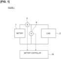
Figure 1 is a block view of a deterioration degree estimation device according to an embodiment of the present invention. The deterioration degree estimation device is provided in a vehicle, and the like, that has a battery. The deterioration degree estimation device is not limited to a vehicle, and can be provided in another device equipped with a battery. - The deterioration degree estimation device comprises a
battery 1, aload 2, acurrent sensor 3, avoltage sensor 4, and abattery controller 10. Thebattery 1 is configured from a plurality of secondary batteries that are connected in series or in parallel. The secondary battery is a lithium ion battery, a nickel hydrogen battery, or the like. Thebattery 1 is connected to a charger, which is not shown. - The
load 2 is connected to thebattery 1 by wiring. Theload 2 is driven by the electric power of thebattery 1. Theload 2 is a motor, or the like. Thecurrent sensor 3 and thevoltage sensor 4 detect the state of the battery, and are electrically connected to thebattery 1. Thecurrent sensor 3 detects the current of thebattery 1. Thevoltage sensor 4 detects the voltage of thebattery 1. The detection values of thecurrent sensor 3 and thevoltage sensor 4 are output to thebattery controller 10. Thebattery controller 10 is a control device for managing the state of thebattery 1. - Next, the configuration of the
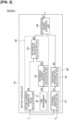
battery controller 10 will be described usingFigure 2. Figure 2 is a block view of thebattery controller 10. Thebattery controller 10 is configured from a CPU, a ROM, and the like. Thebattery controller 10 comprises a controller illustrated inFigure 2 as a function block for estimating the deterioration degree of thebattery 1. Thebattery controller 10 comprises an internalresistance management unit 20, adeterioration management unit 30, and a deteriorationdegree estimation unit 40. - The internal
resistance management unit 20 monitors the internal resistance of thebattery 1 on the basis of the detected current of thecurrent sensor 3 and the detected voltage of thevoltage sensor 4. The internalresistance management unit 20 comprises an internalresistance detection unit 21 and a resistance increaserate calculation unit 22. - The internal
resistance detection unit 21 detects (calculates) the internal resistance of thebattery 1 on the basis of the detected value of thecurrent sensor 3 and the detected value of thevoltage sensor 4. The resistance increaserate calculation unit 22 calculates the increase rate of the internal resistance. - The
deterioration management unit 30 monitors the cycle deterioration of thebattery 1. In the present embodiment, thedeterioration management unit 30 monitors the cycle deterioration degree by calculating the current integration value of thebattery 1. Thedeterioration management unit 30 comprises an actual current integrationvalue calculation unit 31, atime management unit 32, a reference current integrationvalue calculation unit 33, and an integration valueratio calculation unit 34. - The actual current integration
value calculation unit 31 calculates the current integration value of thebattery 1 by integrating the detected current of thecurrent sensor 3. Thetime management unit 32 monitors the elapsed time from the start of use of thebattery 1. The reference current integrationvalue calculation unit 33 calculates a reference current integration value on the basis of the elapsed time that is monitored by thetime management unit 32. The current integration value that is calculated by the actual current integrationvalue calculation unit 31 is the integrated value of the actual discharge current. On the other hand, the reference current integration value that is calculated by the reference current integrationvalue calculation unit 33 is a current integration value corresponding to the elapsed time, and is not an integrated value of the actual discharge current. - The integration value
ratio calculation unit 34 calculates the ratio of the current integration value. The ratio is the actual current integration value relative to the reference current integration value. - The deterioration
degree estimation unit 40 calculates the deterioration degree of thebattery 1 on the basis of the internal resistance of thebattery 1. In addition, the deteriorationdegree estimation unit 40 corrects the deterioration degree corresponding to the internal resistance, in accordance with the magnitude of the current integration value ratio that is calculated by the integration valueratio calculation unit 34. The deteriorationdegree estimation unit 40 thereby estimates the corrected deterioration degree as the final deterioration degree of thebattery 1. - Next, the method of estimating the deterioration degree of the
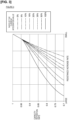
battery 1 will be described with reference toFigure 2 andFigure 3. Figure 3 is a graph illustrating the correspondence between the resistance increase rate, the ratio of the current integration value, and the capacity retention rate. Steps S1-S7 of the block view ofFigure 2 illustrate the control flow of the deterioration degree estimation method. - The internal
resistance detection unit 21 uses acurrent sensor 3 and avoltage sensor 4 to acquire the detected current and the detected voltage, plots the acquired detected current and detected voltage on a graph having the current value and the voltage value as axes, and, at the same time, calculates the IV characteristic, which is a straight line approximating the plotted current value and voltage value, and calculates the internal resistance from the inclination of the IV characteristic (Step S1). The method of calculating the internal resistance is not limited to the method of calculating from the inclination oxide film layer the IV characteristic, and can be another method. For example, the internal resistance can be calculated by substituting the current value detected by thecurrent sensor 3 and the voltage value detected by thevoltage sensor 4 into a battery model formula, which is stored in advance and which includes the current value, voltage value, and internal resistance in the parameter. Since these internal resistance calculation methods are well-known, the details are not described herein. - The resistance increase
rate calculation unit 22 calculates the resistance increase rate by calculating the ratio of the initial value of the internal resistance (the internal resistance value corresponding to the internal resistance value when thebattery 1 is new, and which is stored in advance), and the internal resistance calculated by the internal resistance detection unit 21 (Step S2). The increase rate of the internal resistance corresponds to the ratio of the calculated value of the internal resistance relative to the initial value of the internal resistance. That is, the resistance increase rate means the increase rate relative to the initial value of the internal resistance. The initial value of the internal resistance can be a value stored in advance in the resistance increaserate calculation unit 22. Alternatively, the initial value can be a value calculated by the internalresistance detection unit 21 at the time of start of use of thebattery 1. The resistance increaserate calculation unit 22 outputs the calculated resistance increase rate to the deteriorationdegree estimation unit 40. - The actual current integration
value calculation unit 31 calculates the actual current integration value of thebattery 1 by integrating the detected current of the current sensor 3 (Step S3). The current integration value is the integrated value of the discharge current of thebattery 1. In addition, the current integration value is the current integration value from the start of use of thebattery 1 to the present. Thetime management unit 32 monitors the elapsed time of thebattery 1, in accordance with the calculation timing of the current integration value by the actual current integration value calculation unit 31 (Step S4). - The reference current integration
value calculation unit 33 calculates the current integration value corresponding to the elapsed time as the reference current integration value (Step S5). The reference current integration value is a value in which the current integration value at the elapsed time is set in advance. The reference current integration value is a value that is set in advance as an evaluation value that evaluates the integrated value of the discharge current under a PR environment. The reference current integration value becomes larger as the elapsed time increases. For example, if 1C charging and 1C discharging are repeated for a predetermined number of times during a predetermined period, the integrated value of the discharge time during the predetermined period becomes the reference current integration value corresponding to said predetermined period. The correspondence relationship between the elapsed time and the reference current integration value is stored in the reference current integrationvalue calculation unit 33 in advance as a map, or the like. - The integration value
ratio calculation unit 34 calculates the ratio of the current integration value (Step S6). The ratio of the current integration value is the ratio of the actual current integration value at a predetermined elapsed time and the reference current integration value corresponding to said elapsed time. If the ratio of the current integration value is high, the actual current integration value becomes large; therefore, the cycle deterioration becomes larger than the storage deterioration. On the other hand, if the ratio of the current integration value is low, the actual current integration value becomes small relative to the current integration value that was evaluated beforehand (corresponding to the reference current integration value); therefore, the cycle deterioration becomes smaller than the storage deterioration. That is, the ratio of the current integration value represents the rate of the influence of cycle deterioration at the elapsed time. Here, in general, storage deterioration is deterioration that occurs over time regardless of the charging and discharging of the battery, and cycle deterioration means deterioration that occurs due to the charging and discharging of the battery. - Meanwhile, as a characteristic of the
battery 1, the internal resistance increases as the deterioration of thebattery 1 progresses. Accordingly, it is possible to calculate the deterioration degree of thebattery 1 from the increase rate of the internal resistance. The deterioration degree of thebattery 1 is represented by the storage deterioration and the cycle deterioration. That is, the deterioration of thebattery 1 includes storage deterioration and cycle deterioration. From the point of view of influence on the deterioration degree, even if the deterioration degree of thebattery 1 is the same value (the increase rate of the internal resistance is the same), the rate at which the storage deterioration influences the deterioration degree and the rate at which the cycle deterioration influences the deterioration degree are different depending on how the battery is used. - Here, it is assumed that a predetermined period has elapsed since the start of use of the
battery 1, and that the increase rate of the internal resistance has reached a predetermined value. If the cycle deterioration has a greater influence on the deterioration degree of thebattery 1 than the storage deterioration when the increase rate of the internal resistance reaches the predetermined value, the deterioration speed of thebattery 1 is high, and the elapsed time from the start of use becomes short. On the other hand, if the storage deterioration has a greater influence on the deterioration degree of thebattery 1 than the cycle deterioration when the increase rate of the internal resistance reaches the predetermined value, the deterioration speed of thebattery 1 is low, and the elapsed time from the start of use becomes long. The deterioration degree of thebattery 1 is larger when the increase rate of the internal resistance reaches the predetermined value over a long time. That is, if the increase rate of the internal resistance is the same, the deterioration degree of thebattery 1 decreases as the cycle deterioration increases, and the deterioration degree of thebattery 1 increases as the storage deterioration increases. The deteriorationdegree estimation unit 40 estimates the deterioration degree of thebattery 1 using this characteristic. - The deterioration
degree estimation unit 40 stores the correspondence relationship between the resistance increase rate, the ratio of the current integration value, and the capacity retention rate as a map. According to the correspondence relationship represented by the map, the capacity retention rate decreases as the resistance increase rate increases, as illustrated inFigure 3 . In addition, when the resistance increase rate is set to a constant value, the capacity retention rate decreases as the ratio of the current integration value decreases. In other words, it can be said that if the deterioration degree of the battery is constant, the capacity retention rate decreases as the ratio of the cycle deterioration decreases, that is, as the ratio of the storage deterioration increases. Furthermore, it can also be said that if the deterioration degree of the battery is constant, the capacity retention rate increases as the ratio of the cycle deterioration increases, that is, as the ratio of the storage deterioration decreases. The capacity retention rate is in an inverse relationship with the deterioration degree of thebattery 1, and the deterioration degree decreases as the capacity retention rate increases. The deteriorationdegree estimation unit 40 refers to a map, and estimates the capacity retention rate corresponding to the resistance increase rate and the ratio of the current integration value as the current capacity retention rate of the battery 1 (Step S7). When the resistance increase rate is the same value, the deteriorationdegree estimation unit 40 estimates the current deterioration degree of thebattery 1 such that the deterioration degree of thebattery 1 decreases as the ratio of the current integration value increases. As a result, the deteriorationdegree estimation unit 40 corrects the resistance deterioration degree calculated based on the internal resistance of thebattery 1 such that the resistance deterioration degree decreases as the cycle deterioration increases, and estimates the corrected resistance deterioration degree as the current deterioration. - As described above, in the present embodiment, the internal resistance of the
battery 1 is calculated, the cycle deterioration of thebattery 1 is monitored, and the deterioration degree of thebattery 1 is estimated based on the increase rate of the internal resistance of thebattery 1. Then, the estimated deterioration degree of thebattery 1 is decreased as the cycle deterioration is increased. It is thereby possible to increase the estimation accuracy of the deterioration degree of thebattery 1. - In addition, in the present embodiment, the cycle deterioration is monitored by calculating the current integration value of the
battery 1. It is thereby possible to easily grasp how thebattery 1 is used. - In addition, in the present embodiment, a map representing the correspondence relationship between the increase rate of the internal resistance, the current integration value, and the deterioration degree is stored in advance, and the deterioration degree is estimated with reference to the map. Since it is thereby possible to grasp the transition of the deterioration degree according to how the battery is used in accordance with the battery characteristics, it is possible to increase the estimation accuracy of the deterioration degree of the
battery 1. - As a modified example of the present embodiment, the deterioration
degree estimation unit 40 can calculate a deterioration degree corresponding to the increase rate of the internal resistance, correct the calculated deterioration degree based on the current integration value, and estimate the corrected deterioration degree as the deterioration degree of thebattery 1. A map representing the correspondence relationship between the increase rate of the internal resistance and the deterioration degree is stored in advance in the deteriorationdegree estimation unit 40. A correction coefficient for correcting the deterioration degree is set in advance in the deteriorationdegree estimation unit 40. The correction coefficient changes according to the current integration value. The maximum value of the correction coefficient is set to 1.0, and the correction coefficient decreases as the ratio of the current integration value decreases. Then, the deteriorationdegree estimation unit 40 estimates the final deterioration degree by multiplying the deterioration degree calculated from the map by the correction coefficient. As a result, when the internal resistance of thebattery 1 reaches a certain internal resistance, the estimated deterioration degree decreases as the cycle deterioration increases. The setting value of the correction coefficient can be a value other than 1.0, and the calculation method for correcting the deterioration degree can be another method. - In addition, as a modified example of the present embodiment, the deterioration
degree estimation unit 40 can correct the increase rate of the internal resistance based on the current integration value. A map representing the correspondence relationship between the increase rate of the internal resistance and the deterioration degree is stored in advance in the deteriorationdegree estimation unit 40. In addition, a correction coefficient for correcting the increase rate of the internal resistance is set in advance in the deteriorationdegree estimation unit 40. The correction coefficient changes according to the current integration value. The maximum value of the correction coefficient is set to 1.0, and the correction coefficient increases as the ratio of the current integration value decreases. The deteriorationdegree estimation unit 40 calculates the corrected internal resistance increase rate by multiplying the increase rate of the internal resistance by the correction coefficient. The corrected internal resistance increase rate increases as the ratio of the current integration value decreases. Then, the deteriorationdegree estimation unit 40 refers to the map, and estimates the deterioration degree corresponding to the corrected internal resistance increase rate as the final deterioration degree. - In addition, as a modified example of the present embodiment, the deterioration
degree estimation unit 40 can correct the deterioration degree based on the temperature of thebattery 1. The deterioration degree of thebattery 1 has a dependency with respect to the temperature, and the degree of progress of deterioration differs depending on the temperature of thebattery 1. Thebattery 1 has a characteristic of being easily deteriorated at a certain temperature and not being easily deteriorated at other temperatures. The deteriorationdegree estimation unit 40 stores a correction coefficient that represents the relationship between deterioration and temperature, and carries out a correction based on the temperature by multiplying the estimated deterioration degree by the correction coefficient. As a result, it is possible to increase the estimation accuracy of the deterioration degree. In addition to a method of multiplying a correction coefficient, the method of correcting the deterioration degree can be a calculation method that uses a map. The temperature of thebattery 1 can be detected by a sensor provided to thebattery 1. - In addition, as a modified example of the present embodiment, the deterioration
degree estimation unit 40 can correct the deterioration degree based on the charging state of the battery 1 (SOC: State of Charge). The deterioration degree of thebattery 1 has a dependency with respect to the SOC, and the degree of progress of deterioration differs depending on the SOC of the battery 1 (the SOC when thebattery 1 is stored, the SOC when thebattery 1 is used). Thebattery 1 has a characteristic of being easily deteriorated at a certain SOC and not being easily deteriorated at other SOCs. The deteriorationdegree estimation unit 40 stores a correction coefficient that represents the relationship between SOC and temperature/II think this should be "relationship between SOC and deterioration degree"//, and carries out a correction based on the SOC by multiplying the estimated deterioration degree by the correction coefficient. As a result, it is possible to increase the estimation accuracy of the deterioration degree. In addition to a method of multiplying a correction coefficient, the method of correcting the deterioration degree can be a calculation method that uses a map. The SOC of thebattery 1 can be obtained by calculation using the detection value of thecurrent sensor 3 or the detection value of thevoltage sensor 4. - A deterioration degree estimation device according to another embodiment of the present invention will be described using
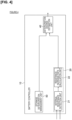
Figure 4 . The present embodiment is different from the first embodiment described above in the point that the storage deterioration of thebattery 1 is monitored, and the deterioration degree of thebattery 1 is estimated in accordance with the magnitude of the storage deterioration. The other configurations are the same as the above-described first embodiment, and the descriptions thereof are incorporated by reference.Figure 4 is a block view of thebattery controller 10. - The
battery controller 10 comprises an internalresistance management unit 20, a deteriorationdegree estimation unit 40, and a storagedeterioration management unit 50. The configuration of the internalresistance management unit 20 is the same as the configuration of the internalresistance management unit 20 according to the first embodiment. - The storage
deterioration management unit 50 monitors the storage deterioration of thebattery 1. In the present embodiment, the storagedeterioration management unit 50 monitors the storage deterioration of thebattery 1 by measuring the elapsed time of thebattery 1 using a timer. Storage deterioration is deterioration that progresses over time due to a chemical reaction between the electrolyte and the electrode of a battery. The storagedeterioration management unit 50 measures the elapsed time since the electrode comes in contact with the electrolyte, and obtains the current storage deterioration based on the elapsed time. - The storage deterioration monitored by the storage
deterioration management unit 50 is set as the storage deterioration from when the electrode comes in contact with the electrolyte to the present time. The storagedeterioration management unit 50 measures the time from when the electrode comes in contact with the electrolyte to the present time as the elapsed time, and calculates the storage deterioration based on the elapsed time. - The characteristic of the storage deterioration is illustrated in
Figure 5. Figure 5 is a graph illustrating the time characteristic of the storage deterioration. InFigure 5 , the horizontal axis represents the square root of time, and the vertical axis represents the deterioration degree of the storage deterioration and the capacity retention rate. The characteristic illustrated inFigure 5 can be acquired using a common storage test for battery evaluation. - Storage deterioration progresses in proportion to the square root of time, as illustrated in
Figure 5 . A map representing the relationship between elapsed time and storage deterioration is stored in the storagedeterioration management unit 50. The storagedeterioration management unit 50 calculates the deterioration degree corresponding to the elapsed time as the storage deterioration with reference to this map. - The deterioration
degree estimation unit 40 stores the correspondence relationship between the resistance increase rate, the storage deterioration degree, and the capacity retention rate as a map. According to the correspondence relationship represented by the map, the capacity retention rate decreases as the resistance increase rate increases. In addition, when the resistance increase rate is set to a constant value, the capacity retention rate decreases as the storage deterioration degree increases. The deteriorationdegree estimation unit 40 refers to a map, and estimates the capacity retention rate corresponding to the resistance increase rate and the storage deterioration degree as the current capacity retention rate of thebattery 1. When the resistance increase rate is the same value, the deteriorationdegree estimation unit 40 estimates the current deterioration degree of thebattery 1 such that the deterioration degree of thebattery 1 increases as the ratio of the storage deterioration degree increases. As a result, the deteriorationdegree estimation unit 40 corrects the resistance deterioration degree calculated based on the internal resistance of thebattery 1 such that the resistance deterioration degree increases as the storage deterioration increases, and estimates the corrected resistance deterioration degree as the current deterioration. - As described above, in the present embodiment, the internal resistance of the
battery 1 is calculated, the storage deterioration of thebattery 1 is monitored, and the deterioration degree of thebattery 1 is estimated based on the increase rate of the internal resistance of thebattery 1. Then, the estimated deterioration degree of thebattery 1 is increased as the storage deterioration is increased. It is thereby possible to increase the estimation accuracy of the deterioration degree of thebattery 1. - Since the storage
deterioration management unit 50 measures time using a timer mounted in a vehicle, the time from when the electrode comes in contact with the electrolyte to when timing with the vehicle timer is started in the battery manufacturing process cannot be timed. Therefore, the time from when the electrode comes in contact with the electrolyte to when timing with the vehicle timer is started can be managed to be a fixed time, and the fixed time can be added to the time measured by the timer. In addition, since the time from when the electrode comes in contact with the electrolyte to when timing with the vehicle timer is started is extremely short compared to the life of thebattery 1, the time can simply be ignored. - In addition, as a modified example of the present embodiment, the storage
deterioration management unit 50 can correct the storage deterioration based on the temperature of thebattery 1. As a characteristic of thebattery 1, storage deterioration has temperature dependence, as illustrated inFigure 6 . -
Figure 6 is a graph illustrating the time characteristics of the deterioration coefficient. InFigure 6 , the horizontal axis represents the square root of time, and the vertical axis represents the deterioration coefficient. The deterioration coefficient is a coefficient that is multiplied by the capacity retention rate. The capacity retention rate becomes smaller and the deterioration degree increases as the deterioration coefficient becomes smaller. In addition, if the time is the same, the deterioration coefficient becomes smaller as the temperature increases. The storagedeterioration management unit 50 stores in advance a correction coefficient that represents the relationship between storage deterioration and temperature. This correction coefficient corresponds to the deterioration coefficient. However, while the deterioration coefficient shown by the characteristic ofFigure 6 is a coefficient that is multiplied by the capacity retention rate, the correction coefficient is set to a coefficient that can calculate the deterioration degree while maintaining the relationship shown by the characteristic ofFigure 6 . - The storage
deterioration management unit 50 uses temperature information that is output by the temperature sensor of thebattery 1 and stores, in a memory, the frequency of the temperature up to this time at a set period unit, based on the time information of the timer. The storagedeterioration management unit 50 corrects the storage deterioration degree using the temperature information stored in the memory. Specifically, for example, the storagedeterioration management unit 50 obtains the time that thebattery 1 is exposed to the temperature, using temperature occurrence frequency information that is stored. Next, the storagedeterioration management unit 50 calculates the storage deterioration degree with respect to the obtained time, and multiplies the storage deterioration degree by the correction coefficient. The storagedeterioration management unit 50 carries out the same calculation for each temperature interval, and calculates the storage deterioration degree for each interval. Then, the storagedeterioration management unit 50 calculates the final storage deterioration degree by calculating the storage deterioration degree for each interval. The storagedeterioration management unit 50 thereby corrects the storage deterioration based on the temperature of thebattery 1. In the present embodiment, it is possible to increase the calculation accuracy of the storage deterioration degree by applying temperature sensitivity to the storage deterioration of thebattery 1. - In addition, as a modified example of the present embodiment, the storage
deterioration management unit 50 can correct the storage deterioration based on the SOC of thebattery 1. As a characteristic of thebattery 1, storage deterioration is dependent on the SOC, as illustrated inFigure 7 . -
Figure 7 is a graph illustrating the time characteristics of the deterioration coefficient. InFigure 7 , the horizontal axis represents the square root of time, and the vertical axis represents the deterioration coefficient. The deterioration coefficient is the same as the deterioration coefficient shown inFigure 6 . The capacity retention rate becomes smaller and the deterioration degree increases as the deterioration coefficient becomes smaller. In addition, if the time is the same, the deterioration coefficient becomes smaller as the SOC increases. - The storage
deterioration management unit 50 stores in advance a correction coefficient that represents the relationship between storage deterioration and SOC. The storagedeterioration management unit 50 uses the SOC, and stores, in a memory, the frequency of the SOC up to this time at a set period unit, based on the time information of the timer. The storagedeterioration management unit 50 corrects the storage deterioration degree using the SOC information stored in the memory. Specifically, for example, the storagedeterioration management unit 50 obtains the time that thebattery 1 maintains the SOC, using the SOC occurrence frequency information that is stored. Next, the storagedeterioration management unit 50 calculates the storage deterioration degree with respect to the obtained time, and multiplies the storage deterioration degree by the correction coefficient. The storagedeterioration management unit 50 carries out the same calculation for each SOC interval, and calculates the storage deterioration degree for each interval. Then, the storagedeterioration management unit 50 calculates the final storage deterioration degree by calculating the storage deterioration degree for each interval. The storagedeterioration management unit 50 thereby corrects the storage deterioration based on the SOC of thebattery 1. In the present embodiment, it is possible to increase the calculation accuracy of the storage deterioration degree by applying the SOC sensitivity to the storage deterioration of thebattery 1. - The storage
deterioration management unit 50 can correct the storage deterioration degree based on the temperature and the SOC of thebattery 1 by combining the two modified examples described above. - The storage
deterioration management unit 50 described above corresponds to the deterioration management unit of the present invention. -
- 1
- Battery
- 2
- Load
- 3
- Current sensor
- 4
- Voltage sensor
- 10
- Battery controller
- 20
- Internal resistance management unit
- 21
- Internal resistance detection unit
- 22
- Resistance increase rate calculation unit
- 30
- Deterioration management unit
- 31
- Actual current integration value calculation unit
- 32
- Time management unit
- 33
- Reference current integration value calculation unit
- 34
- Integration value ratio calculation unit
- 40
- Deterioration degree estimation unit
- 50
- Storage deterioration management unit
Claims (8)
- A deterioration degree estimation device comprising:an internal resistance detection unit (21) for detecting an internal resistance of a battery;a deterioration management unit (30, 50) for monitoring a cycle deterioration of the battery and a storage deterioration of the battery, the cycle deterioration being deterioration that occurs due to the charging and discharging of the battery, the storage deterioration being deterioration that occurs over time regardless of the charging and discharging of the battery; anda deterioration degree estimation unit (40) for estimating a deterioration degree of the battery,characterized bya resistance increase rate calculation unit (22) configured to calculate an increase rate of the internal resistance, the increase rate of the internal resistance being a ratio of a calculated value of the internal resistance relative to an initial value of the internal resistance,whereinthe deterioration degree estimation unit is configured to estimate the deterioration degree of the battery as an estimated deterioration degree based on the increase rate of the internal resistance such that the estimated deterioration degree decreases as a cycle deterioration degree increases, and such that the estimated deterioration degree increases as a storage deterioration degree increases.
- The deterioration degree estimation device according to claim 1, wherein
the deterioration management unit (30) is configured to monitor the cycle deterioration by calculating a current integration value of the battery. - The deterioration degree estimation device according to claim 2, wherein
the deterioration degree estimation unit (40) is configured to store a map representing a correspondence relationship between the increase rate of the internal resistance, the current integration value, and the estimated deterioration degree, and estimate the estimated deterioration degree with reference to the map. - The deterioration degree estimation device according to claim 2 or 3, wherein
the deterioration degree estimation unit (40) is configured to correct the increase rate of the internal resistance based on the current integration value. - The deterioration degree estimation device according to claim 2 or 3, wherein
the deterioration degree estimation unit (40) is configured to calculate the deterioration degree of the battery corresponding to the increase rate of the internal resistance as a reference deterioration degree, correct the reference deterioration degree based on the current integration value, and estimate a corrected reference deterioration degree as the estimated deterioration degree. - The deterioration degree estimation device according to any one of claims 1 to 5, wherein
the deterioration degree estimation unit (40) is configured to correct the estimated deterioration degree based on a temperature of the battery. - The deterioration degree estimation device according to any one of claims 1 to 5, wherein
the deterioration degree estimation unit (40) is configured to correct the estimated deterioration degree based on a charging state of the battery. - A deterioration degree estimation method comprising:detecting an internal resistance of a battery;monitoring a cycle deterioration of the battery and a storage deterioration of the battery, the cycle deterioration being deterioration that occurs due to the charging and discharging of the battery, the storage deterioration being deterioration that occurs over time regardless of the charging and discharging of the battery; andestimating a deterioration degree of the battery,characterized bycalculating an increase rate of the internal resistance, the increase rate of the internal resistance being a ratio of a calculated value of the internal resistance relative to an initial value of the internal resistance,whereinthe estimating estimates the deterioration degree of the battery as an estimated deterioration degree based on the increase rate of the internal resistance such that the estimated deterioration degree decreases as a cycle deterioration degree increases, and such that the estimated deterioration degree increases as a storage deterioration degree increases.
Applications Claiming Priority (1)
| Application Number | Priority Date | Filing Date | Title |
|---|---|---|---|
| PCT/JP2015/074021 WO2017033311A1 (en) | 2015-08-26 | 2015-08-26 | Deterioration degree estimation device and deterioration degree estimation method |
Publications (3)
| Publication Number | Publication Date |
|---|---|
| EP3343689A1 EP3343689A1 (en) | 2018-07-04 |
| EP3343689A4 EP3343689A4 (en) | 2018-11-21 |
| EP3343689B1 true EP3343689B1 (en) | 2024-02-14 |
Family
ID=58100220
Family Applications (1)
| Application Number | Title | Priority Date | Filing Date |
|---|---|---|---|
| EP15902280.5A Active EP3343689B1 (en) | 2015-08-26 | 2015-08-26 | Deterioration degree estimation device and deterioration degree estimation method |
Country Status (5)
| Country | Link |
|---|---|
| US (1) | US11022653B2 (en) |
| EP (1) | EP3343689B1 (en) |
| JP (1) | JP6414336B2 (en) |
| CN (1) | CN107925135B (en) |
| WO (1) | WO2017033311A1 (en) |
Families Citing this family (13)
| Publication number | Priority date | Publication date | Assignee | Title |
|---|---|---|---|---|
| JP6844464B2 (en) * | 2017-07-25 | 2021-03-17 | トヨタ自動車株式会社 | Battery system |
| WO2019026142A1 (en) * | 2017-07-31 | 2019-02-07 | 日産自動車株式会社 | Deterioration state computation method and deterioration state computation device |
| US10948546B2 (en) * | 2017-10-02 | 2021-03-16 | Semiconductor Components Industries, Llc | Methods and apparatus for battery management |
| JP2019113410A (en) * | 2017-12-22 | 2019-07-11 | 三菱自動車工業株式会社 | Device for estimating state of degradation of secondary battery |
| JP2020060453A (en) * | 2018-10-10 | 2020-04-16 | 本田技研工業株式会社 | Deriving apparatus, deriving method and program |
| JP7119882B2 (en) * | 2018-10-15 | 2022-08-17 | 富士通株式会社 | Deterioration Prediction Program, Deterioration Prediction Method, and Deterioration Prediction Apparatus |
| KR102520673B1 (en) * | 2019-03-18 | 2023-04-10 | 주식회사 엘지에너지솔루션 | Apparatus for estimating state of battery |
| KR102521577B1 (en) * | 2019-03-18 | 2023-04-12 | 주식회사 엘지에너지솔루션 | Apparatus for estimating state of battery |
| JP6722954B1 (en) * | 2019-04-02 | 2020-07-15 | 東洋システム株式会社 | Battery residual value determination system |
| JP6722955B1 (en) * | 2019-04-02 | 2020-07-15 | 東洋システム株式会社 | Battery residual value display |
| JP7363086B2 (en) * | 2019-04-26 | 2023-10-18 | 株式会社Gsユアサ | Estimation device, estimation method |
| JP7312636B2 (en) * | 2019-07-24 | 2023-07-21 | 株式会社日立産機システム | Elapsed time display system, electric machine, and method for calculating elapsed time |
| KR20230019315A (en) * | 2021-07-29 | 2023-02-08 | 현대자동차주식회사 | Method and system for estimating degradation of battery for vehicle |
Family Cites Families (33)
| Publication number | Priority date | Publication date | Assignee | Title |
|---|---|---|---|---|
| JP3807965B2 (en) * | 2001-09-19 | 2006-08-09 | インターナショナル・ビジネス・マシーンズ・コーポレーション | Intelligent battery, electric device, computer device, and method for determining battery deterioration |
| JP4311168B2 (en) | 2003-11-14 | 2009-08-12 | ソニー株式会社 | Battery pack and remaining battery charge calculation method |
| JP4736317B2 (en) * | 2003-11-14 | 2011-07-27 | ソニー株式会社 | Battery pack and remaining battery charge calculation method |
| DE102004007904B4 (en) * | 2004-02-18 | 2008-07-03 | Vb Autobatterie Gmbh & Co. Kgaa | Method for determining at least one parameter for the state of an electrochemical storage battery and monitoring device |
| JP2008228492A (en) | 2007-03-14 | 2008-09-25 | Sanyo Electric Co Ltd | Method for charging lithium ion secondary battery |
| US7714736B2 (en) * | 2007-10-30 | 2010-05-11 | Gm Global Technology Operations, Inc. | Adaptive filter algorithm for estimating battery state-of-age |
| JP2009193919A (en) * | 2008-02-18 | 2009-08-27 | Panasonic Corp | Circuit for estimating residual lifetime and estimation method for residual lifetime |
| US8283891B2 (en) * | 2008-03-21 | 2012-10-09 | Rochester Institute Of Technology | Power source health assessment methods and systems thereof |
| CN102859377B (en) * | 2010-04-26 | 2014-11-05 | 丰田自动车株式会社 | Degradation estimation device and degradation estimation method for storage battery device |
| US8452556B2 (en) * | 2010-09-22 | 2013-05-28 | GM Global Technology Operations LLC | Method and apparatus for estimating SOC of a battery |
| JP5342583B2 (en) * | 2011-03-08 | 2013-11-13 | 三菱重工業株式会社 | Battery cell control device and battery cell |
| EP2746796B1 (en) * | 2011-08-03 | 2016-07-20 | Toyota Jidosha Kabushiki Kaisha | Device for estimating state of deterioration of secondary battery and method for estimating state of deterioration |
| WO2013046263A1 (en) * | 2011-09-28 | 2013-04-04 | トヨタ自動車株式会社 | Control device and control method for non-aqueous secondary battery |
| US20140225621A1 (en) * | 2011-10-13 | 2014-08-14 | Toyota Jidosha Kabushiki Kaisha | Control device and control method for secondary battery |
| JP5839052B2 (en) * | 2012-02-17 | 2016-01-06 | トヨタ自動車株式会社 | Battery system and deterioration determination method |
| WO2013141100A1 (en) * | 2012-03-21 | 2013-09-26 | 三洋電機株式会社 | Cell state estimation device |
| JP6155781B2 (en) * | 2012-05-10 | 2017-07-05 | 株式会社Gsユアサ | Storage element management device and SOC estimation method |
| US9018913B2 (en) * | 2012-05-18 | 2015-04-28 | Caterpillar Inc. | System for determining battery impedance |
| JP2013247003A (en) * | 2012-05-28 | 2013-12-09 | Sony Corp | Charge control device for secondary battery, charge control method for secondary battery, charged state estimation device for secondary battery, charged state estimation method for secondary battery, deterioration degree estimation device for secondary battery, deterioration degree estimation method for secondary battery, and secondary battery device |
| CN104662766B (en) * | 2012-09-21 | 2018-04-10 | 日产自动车株式会社 | Charged state arithmetic unit and charged state operation method |
| JP5840116B2 (en) | 2012-11-22 | 2016-01-06 | 古河電気工業株式会社 | Secondary battery state estimation apparatus and method |
| WO2014083856A1 (en) * | 2012-11-30 | 2014-06-05 | 三洋電機株式会社 | Battery management device, power supply, and soc estimation method |
| JP5708668B2 (en) * | 2013-01-18 | 2015-04-30 | トヨタ自動車株式会社 | Power storage system |
| JP5803965B2 (en) * | 2013-03-25 | 2015-11-04 | トヨタ自動車株式会社 | vehicle |
| CN105164392B (en) * | 2013-04-30 | 2018-01-19 | 三菱电机株式会社 | Battery condition detection device and battery condition detection method |
| JP5765375B2 (en) * | 2013-07-25 | 2015-08-19 | トヨタ自動車株式会社 | Control apparatus and control method |
| FR3009093B1 (en) * | 2013-07-29 | 2017-01-13 | Renault Sa | ESTIMATING THE AGING CONDITION OF AN ELECTRIC BATTERY |
| JP5862631B2 (en) * | 2013-10-08 | 2016-02-16 | トヨタ自動車株式会社 | Power storage system |
| JP6110771B2 (en) * | 2013-10-22 | 2017-04-05 | 三菱重工業株式会社 | Deterioration amount calculation device, deterioration amount calculation method, and program |
| JP2015155859A (en) * | 2014-02-21 | 2015-08-27 | ソニー株式会社 | Battery residual amount estimation device, battery pack, power storage device, electric vehicle and battery residual amount estimation method |
| JP6154352B2 (en) * | 2014-04-21 | 2017-06-28 | トヨタ自動車株式会社 | Battery system |
| JP6164168B2 (en) * | 2014-06-26 | 2017-07-19 | トヨタ自動車株式会社 | Vehicle control device |
| JP6245094B2 (en) * | 2014-06-30 | 2017-12-13 | 日立化成株式会社 | Battery system |
-
2015
- 2015-08-26 EP EP15902280.5A patent/EP3343689B1/en active Active
- 2015-08-26 US US15/754,607 patent/US11022653B2/en active Active
- 2015-08-26 JP JP2017536134A patent/JP6414336B2/en active Active
- 2015-08-26 CN CN201580082690.2A patent/CN107925135B/en active Active
- 2015-08-26 WO PCT/JP2015/074021 patent/WO2017033311A1/en active Application Filing
Also Published As
| Publication number | Publication date |
|---|---|
| US11022653B2 (en) | 2021-06-01 |
| WO2017033311A1 (en) | 2017-03-02 |
| EP3343689A1 (en) | 2018-07-04 |
| CN107925135A (en) | 2018-04-17 |
| JPWO2017033311A1 (en) | 2018-07-05 |
| CN107925135B (en) | 2021-09-07 |
| US20180246174A1 (en) | 2018-08-30 |
| JP6414336B2 (en) | 2018-11-07 |
| EP3343689A4 (en) | 2018-11-21 |
Similar Documents
| Publication | Publication Date | Title |
|---|---|---|
| EP3343689B1 (en) | Deterioration degree estimation device and deterioration degree estimation method | |
| US8664960B2 (en) | Charged state estimating device and charged state estimating method of secondary battery | |
| US9660299B2 (en) | Strain measurement based battery testing | |
| US7630842B2 (en) | Secondary battery charge/discharge electricity amount estimation method and device, secondary battery polarization voltage estimation method and device and secondary battery remaining capacity estimation method and device | |
| EP2728368B1 (en) | Condition estimation device and method for battery | |
| EP2664938B1 (en) | Open circuit voltage estimation device, condition estimation device, and method of estimating open circuit voltage | |
| US9400313B2 (en) | Method and device for determining the actual capacity of a battery | |
| WO2008026476A1 (en) | Method and device for estimating soc value of secondary battery and degradation judging method and device | |
| EP3379277B1 (en) | Capacity maintenance rate estimation apparatus or capacity maintenance rate estimation method | |
| CN103969590A (en) | Battery management system and method of using same | |
| JP5565276B2 (en) | Method for correcting the amount of charge in a lithium ion battery | |
| US20140365150A1 (en) | Method and device for determining a charge state of an electric energy store | |
| JP5911407B2 (en) | Battery soundness calculation device and soundness calculation method | |
| JP2004271342A (en) | Charging and discharging control system | |
| KR20180082020A (en) | device for detecting the state of charge of a battery | |
| JP2014109535A (en) | Internal resistance estimation device, charging apparatus, discharging apparatus, and internal resistance estimation method | |
| JP5904916B2 (en) | Battery soundness calculation device and soundness calculation method | |
| JP2004177373A (en) | Method of estimating battery condition, and method of determining engine start | |
| CN114859256A (en) | Method and device for predicting remaining available energy of battery pack | |
| JP2014059251A (en) | Internal resistance estimation device and internal resistance estimation method | |
| JP2004045235A (en) | Method of estimating internal resistance, method of estimating charged condition, and method of determining start of engine | |
| JP2003051341A (en) | Residual capacity meter for battery | |
| CN115042666A (en) | Calculation method and calculation system for internal temperature of power battery |
Legal Events
| Date | Code | Title | Description |
|---|---|---|---|
| STAA | Information on the status of an ep patent application or granted ep patent |
Free format text: STATUS: THE INTERNATIONAL PUBLICATION HAS BEEN MADE |
|
| PUAI | Public reference made under article 153(3) epc to a published international application that has entered the european phase |
Free format text: ORIGINAL CODE: 0009012 |
|
| STAA | Information on the status of an ep patent application or granted ep patent |
Free format text: STATUS: REQUEST FOR EXAMINATION WAS MADE |
|
| 17P | Request for examination filed |
Effective date: 20180316 |
|
| AK | Designated contracting states |
Kind code of ref document: A1 Designated state(s): AL AT BE BG CH CY CZ DE DK EE ES FI FR GB GR HR HU IE IS IT LI LT LU LV MC MK MT NL NO PL PT RO RS SE SI SK SM TR |
|
| AX | Request for extension of the european patent |
Extension state: BA ME |
|
| A4 | Supplementary search report drawn up and despatched |
Effective date: 20181022 |
|
| RIC1 | Information provided on ipc code assigned before grant |
Ipc: H01M 10/48 20060101AFI20181012BHEP Ipc: H02J 7/00 20060101ALI20181012BHEP Ipc: G01R 31/36 20060101ALI20181012BHEP |
|
| DAV | Request for validation of the european patent (deleted) | ||
| DAX | Request for extension of the european patent (deleted) | ||
| REG | Reference to a national code |
Ref country code: DE Ref legal event code: R079 Ref document number: 602015087569 Country of ref document: DE Free format text: PREVIOUS MAIN CLASS: H01M0010480000 Ipc: G01R0031360000 Ref country code: DE Ref legal event code: R079 Ipc: G01R0031360000 |
|
| STAA | Information on the status of an ep patent application or granted ep patent |
Free format text: STATUS: EXAMINATION IS IN PROGRESS |
|
| RIC1 | Information provided on ipc code assigned before grant |
Ipc: G01R 31/392 20190101ALI20220111BHEP Ipc: G01R 31/389 20190101ALI20220111BHEP Ipc: H02J 7/00 20060101ALI20220111BHEP Ipc: H01M 10/48 20060101ALI20220111BHEP Ipc: G01R 31/36 20060101AFI20220111BHEP |
|
| 17Q | First examination report despatched |
Effective date: 20220214 |
|
| GRAP | Despatch of communication of intention to grant a patent |
Free format text: ORIGINAL CODE: EPIDOSNIGR1 |
|
| STAA | Information on the status of an ep patent application or granted ep patent |
Free format text: STATUS: GRANT OF PATENT IS INTENDED |
|
| INTG | Intention to grant announced |
Effective date: 20231121 |
|
| GRAS | Grant fee paid |
Free format text: ORIGINAL CODE: EPIDOSNIGR3 |
|
| GRAA | (expected) grant |
Free format text: ORIGINAL CODE: 0009210 |
|
| STAA | Information on the status of an ep patent application or granted ep patent |
Free format text: STATUS: THE PATENT HAS BEEN GRANTED |
|
| AK | Designated contracting states |
Kind code of ref document: B1 Designated state(s): AL AT BE BG CH CY CZ DE DK EE ES FI FR GB GR HR HU IE IS IT LI LT LU LV MC MK MT NL NO PL PT RO RS SE SI SK SM TR |
|
| REG | Reference to a national code |
Ref country code: GB Ref legal event code: FG4D |
|
| REG | Reference to a national code |
Ref country code: CH Ref legal event code: EP |
|
| REG | Reference to a national code |
Ref country code: DE Ref legal event code: R096 Ref document number: 602015087569 Country of ref document: DE |
|
| REG | Reference to a national code |
Ref country code: IE Ref legal event code: FG4D |