EP3343578A1 - Working electrode of dye-sensitized solar cell - Google Patents
Working electrode of dye-sensitized solar cell Download PDFInfo
- Publication number
- EP3343578A1 EP3343578A1 EP17211134.6A EP17211134A EP3343578A1 EP 3343578 A1 EP3343578 A1 EP 3343578A1 EP 17211134 A EP17211134 A EP 17211134A EP 3343578 A1 EP3343578 A1 EP 3343578A1
- Authority
- EP
- European Patent Office
- Prior art keywords
- group
- dye
- working electrode
- oxide semiconductor
- bonded
- Prior art date
- Legal status (The legal status is an assumption and is not a legal conclusion. Google has not performed a legal analysis and makes no representation as to the accuracy of the status listed.)
- Withdrawn
Links
Images



Classifications
-
- H—ELECTRICITY
- H01—ELECTRIC ELEMENTS
- H01G—CAPACITORS; CAPACITORS, RECTIFIERS, DETECTORS, SWITCHING DEVICES, LIGHT-SENSITIVE OR TEMPERATURE-SENSITIVE DEVICES OF THE ELECTROLYTIC TYPE
- H01G9/00—Electrolytic capacitors, rectifiers, detectors, switching devices, light-sensitive or temperature-sensitive devices; Processes of their manufacture
- H01G9/20—Light-sensitive devices
- H01G9/2027—Light-sensitive devices comprising an oxide semiconductor electrode
- H01G9/2031—Light-sensitive devices comprising an oxide semiconductor electrode comprising titanium oxide, e.g. TiO2
-
- H—ELECTRICITY
- H01—ELECTRIC ELEMENTS
- H01G—CAPACITORS; CAPACITORS, RECTIFIERS, DETECTORS, SWITCHING DEVICES, LIGHT-SENSITIVE OR TEMPERATURE-SENSITIVE DEVICES OF THE ELECTROLYTIC TYPE
- H01G9/00—Electrolytic capacitors, rectifiers, detectors, switching devices, light-sensitive or temperature-sensitive devices; Processes of their manufacture
- H01G9/0029—Processes of manufacture
-
- H—ELECTRICITY
- H01—ELECTRIC ELEMENTS
- H01G—CAPACITORS; CAPACITORS, RECTIFIERS, DETECTORS, SWITCHING DEVICES, LIGHT-SENSITIVE OR TEMPERATURE-SENSITIVE DEVICES OF THE ELECTROLYTIC TYPE
- H01G9/00—Electrolytic capacitors, rectifiers, detectors, switching devices, light-sensitive or temperature-sensitive devices; Processes of their manufacture
- H01G9/20—Light-sensitive devices
- H01G9/2059—Light-sensitive devices comprising an organic dye as the active light absorbing material, e.g. adsorbed on an electrode or dissolved in solution
-
- H—ELECTRICITY
- H10—SEMICONDUCTOR DEVICES; ELECTRIC SOLID-STATE DEVICES NOT OTHERWISE PROVIDED FOR
- H10K—ORGANIC ELECTRIC SOLID-STATE DEVICES
- H10K85/00—Organic materials used in the body or electrodes of devices covered by this subclass
- H10K85/30—Coordination compounds
- H10K85/341—Transition metal complexes, e.g. Ru(II)polypyridine complexes
- H10K85/344—Transition metal complexes, e.g. Ru(II)polypyridine complexes comprising ruthenium
-
- Y—GENERAL TAGGING OF NEW TECHNOLOGICAL DEVELOPMENTS; GENERAL TAGGING OF CROSS-SECTIONAL TECHNOLOGIES SPANNING OVER SEVERAL SECTIONS OF THE IPC; TECHNICAL SUBJECTS COVERED BY FORMER USPC CROSS-REFERENCE ART COLLECTIONS [XRACs] AND DIGESTS
- Y02—TECHNOLOGIES OR APPLICATIONS FOR MITIGATION OR ADAPTATION AGAINST CLIMATE CHANGE
- Y02E—REDUCTION OF GREENHOUSE GAS [GHG] EMISSIONS, RELATED TO ENERGY GENERATION, TRANSMISSION OR DISTRIBUTION
- Y02E10/00—Energy generation through renewable energy sources
- Y02E10/50—Photovoltaic [PV] energy
- Y02E10/542—Dye sensitized solar cells
-
- Y—GENERAL TAGGING OF NEW TECHNOLOGICAL DEVELOPMENTS; GENERAL TAGGING OF CROSS-SECTIONAL TECHNOLOGIES SPANNING OVER SEVERAL SECTIONS OF THE IPC; TECHNICAL SUBJECTS COVERED BY FORMER USPC CROSS-REFERENCE ART COLLECTIONS [XRACs] AND DIGESTS
- Y02—TECHNOLOGIES OR APPLICATIONS FOR MITIGATION OR ADAPTATION AGAINST CLIMATE CHANGE
- Y02E—REDUCTION OF GREENHOUSE GAS [GHG] EMISSIONS, RELATED TO ENERGY GENERATION, TRANSMISSION OR DISTRIBUTION
- Y02E10/00—Energy generation through renewable energy sources
- Y02E10/50—Photovoltaic [PV] energy
- Y02E10/549—Organic PV cells
-
- Y—GENERAL TAGGING OF NEW TECHNOLOGICAL DEVELOPMENTS; GENERAL TAGGING OF CROSS-SECTIONAL TECHNOLOGIES SPANNING OVER SEVERAL SECTIONS OF THE IPC; TECHNICAL SUBJECTS COVERED BY FORMER USPC CROSS-REFERENCE ART COLLECTIONS [XRACs] AND DIGESTS
- Y02—TECHNOLOGIES OR APPLICATIONS FOR MITIGATION OR ADAPTATION AGAINST CLIMATE CHANGE
- Y02P—CLIMATE CHANGE MITIGATION TECHNOLOGIES IN THE PRODUCTION OR PROCESSING OF GOODS
- Y02P70/00—Climate change mitigation technologies in the production process for final industrial or consumer products
- Y02P70/50—Manufacturing or production processes characterised by the final manufactured product
Definitions
- the present invention relates to a working electrode of a dye-sensitized solar cell, and more particularly, to a working electrode of a dye-sensitized solar cell capable of enhancing a bond between a dye and a oxide semiconductor to secure reliability and efficiency of a dye-sensitized solar cell.
- dye-sensitized solar cell includes, as main components, a conductive substrate (a substrate 101 on which a conductive film 102 is formed), a oxide semiconductor 103, a dye 104, an electrolyte 110, and a counter electrode 120 (a substrate 121 on which an electrode material 122 is formed).
- the dye 104 is adsorbed onto the oxide semiconductor 103 and electrons excited by light are injected into the oxide semiconductor 103 to drive the dye-sensitized solar cell.
- the adsorption between the dye 104 and the oxide semiconductor 103 is performed through a immersing method, and the immersing method has a disadvantage in that the working electrode is damaged and a large number of physical bonds between the dyes 104 occur due to prolonged immersing time.
- the physical bond by aggregation between the dyes 104 causes a phenomenon that the dye 104 is separated into the electrolyte 110 when the dye-sensitized solar cell is driven at a high temperature. Most of the separated dyes 104 float in the electrolyte 110, but some of the dyes 104 again form a bond with the oxide semiconductor 103 or form a bond with the conductive film substrate 102. In particular, when a bond with a counter electrode material 122 is formed, a redox reaction between the electrolyte 110 and the counter electrode 120 is affected, and thus, a fill factor (FF) is lowered and efficiency is greatly reduced.
- FF fill factor
- the present invention has been made in an effort to provide a working electrode of a dye-sensitized solar cell having advantages of enhancing a bond between a dye and a oxide semiconductor to prevent the dye from being separated from the oxide semiconductor, and securing reliability and efficiency of a dye-sensitized solar cell.
- An exemplary embodiment of the present invention provides a dye-sensitized solar cell capable of securing reliability and efficiency by including the working electrode of the dye-sensitized solar cell.
- a ratio at which the two or more anchoring groups of the dye are bonded to the oxide semiconductor may be 60% or more of an entire dye.
- a ratio at which the two or more anchoring groups of the dye are bonded to the oxide semiconductor may be 80% or more of an entire dye.
- a ratio at which the two or more anchoring groups of the dye are bonded to the oxide semiconductor may be 90% or more of an entire dye.
- the oxide semiconductor may be titanium dioxide (TiO 2 ).
- the anchoring group of the dye may be any one selected from the group consisting of a carboxyl group (-COOH), a cyanoacrylic acid group, an alkoxysilyl group, a pyridine group, a phosphonic acid group, a tetracyanate group, a perylene dicarboxylic acid anhydride group, a 2-hydroxylbenzonitrile group, a 8-hydroxylquinoline group, a pyridine-N-oxide group, a hydroxylpyridium group, a catechol group, a hydroxamate group, a sulfonic acid group, an acetylacetanate group, a boronic acid group, a nitro group, a tetrazole group, a rhodamine group, and a salicylic acid group.
- a carboxyl group -COOH
- a cyanoacrylic acid group an alkoxysilyl group
- a pyridine group a phosphonic
- the dye may be a metal complex dye or an organic dye.
- Another embodiment of the present invention provides a dye-sensitized solar cell including: the working electrode as described above.
- Another embodiment of the present invention provides a manufacturing method of the working electrode as described above.
- the bond between the dye and the oxide semiconductor may be enhanced to prevent the dye from being separated from the oxide semiconductor, and to secure reliability and efficiency of the dye-sensitized solar cell.
- a working electrode 100 of a dye-sensitized solar cell of the present invention includes a oxide semiconductor 103; and a dye 104 having two or more anchoring groups, wherein the two or more anchoring groups of the dye 104 are bonded to the oxide semiconductor 103.
- the working electrode 100 of the dye-sensitized solar cell is manufactured by depositing a conductive film 102 on a working electrode substrate 101, then depositing the oxide semiconductor 103 on the conductive film 102, and immersing the working electrode on which the oxide 103 is deposited on a dye solution in which the dye 104 is dissolved to thereby adsorb the dye 104 onto the oxide 103.
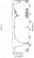
- the FT-IR analysis results of the working electrode 100 including the oxide semiconductor 103 deposited on the conductive film 102 are shown in FIG. 2
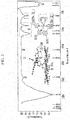
- the FT-IR analysis results of the working electrode 100 including the oxide 103 onto which the dye 104 is adsorbed through a conventional immersing method are shown in FIG. 3 .
- an adsorption time is required to be 12 hours or more, and thus, the working electrode 100 may be damaged due to immersing on the dye solution for a long time, and as shown in FIG. 3 , only one of the two anchoring groups included in the dye 104 bonds with the oxide 103, and thus, a binding force between the dye 104 and the oxide 103 is weaken, and the bond between the dyes is formed.
- a ratio at which the two or more anchoring groups of the dye 104 are bonded to the oxide semiconductor 103 may be 60% or more of an entire dye 104.
- a ratio at which the two or more anchoring groups of the dye 104 are bonded to the oxide semiconductor 103 may be 80% or more of an entire dye 104. More preferably, a ratio at which the two or more anchoring groups of the dye 104 are bonded to the oxide semiconductor 103 may be 90% or more of an entire dye 104.
- the ratio at which the two or more anchoring groups of the dye are bonded to the oxide semiconductor is several % or more of the entire dye means a probability that there is almost no -OH peak that is not bonded with titanium dioxide at the anchoring group of the dye, as a result of spot sampling on any 10 points of a dye-sensitized solar cell module including the working electrode 100, and measuring FT-IR thereon as shown in FIG. 4 .
- FIG. 4 shows FT-IR measured after the working electrode 100 is manufactured by using a working electrode substrate 101 on which titanium dioxide is formed as the oxide semiconductor 103, using a ruthenium-based dye as the dye 104, and applying an electric field to adsorb the dye.
- a working electrode substrate 101 on which titanium dioxide is formed as the oxide semiconductor 103 using a ruthenium-based dye as the dye 104, and applying an electric field to adsorb the dye.
- -OH peak ⁇ peak in FIG. 3
- the manufacturing method of the working electrode 100 will be described in detail.
- the working electrode 100 may be manufactured by applying a voltage to a dye solution in which the dye 104 including the two or more anchoring groups is dissolved, and immersing the working electrode 100 in which the conductive film 102 and the oxide semiconductor 103 are sequentially deposited on the substrate 101 on the dye 104 solution to adsorb the dye 104 onto the oxide semiconductor 103 through electric field adsorption.
- the working electrode 100 and a conductive counter electrode 120 are prepared, the working electrode 100 including the conductive film 102 and the oxide semiconductor 103 sequentially formed on the working electrode substrate 101 and the conductive counter electrode 120 including an electrode material 122 formed on a counter electrode substrate 121.
- the electrode material 122 is not required to be formed, and other types of conductive substrates may be used in place of the counter electrode 120.
- the solution in which the dye 104 is dissolved is prepared, and the dye solution is filled in a bath 500 as shown in FIG. 5 .
- a (+) voltage is applied to the working electrode 100 and a (-) voltage is applied to the counter electrode 120, and thus, the dye 104 is adsorbed onto the oxide 103.
- the voltage V to be applied may be 100V or less, preferably 10V or less.
- a temperature of the solution may be 25 to 60 ⁇ , preferably 50 to 60 ⁇ , and an adsorption time may be 10 minutes to 1 hour, preferably 30 minutes to 1 hour, but the temperature of the solution and the adsorption time are not limited thereto.
- the electric field adsorption is performed as described above, the dye 104 is bonded to the oxide semiconductor 103, and in the bonded dye 104, the two or more anchoring groups are bonded to the oxide semiconductor 103.
- the oxide semiconductor 103 is not particularly limited, but specifically, may be titanium dioxide (TiO 2 ).
- the anchoring group of the dye 104 in the working electrode 100 of the present invention is not particularly limited, but specifically, the anchoring group of the dye may be configured of a material including two or more of any one selected from the group consisting of a carboxyl group (-COOH), a cyanoacrylic acid group, an alkoxysilyl group, a pyridine group, a phosphonic acid group, a tetracyanate group, a perylene dicarboxylic acid anhydride group, a 2-hydroxylbenzonitrile group, a 8-hydroxylquinoline group, a pyridine-N-oxide group, a hydroxylpyridium group, a catechol group, a hydroxamate group, a sulfonic acid group, an acetylacetanate group, a boronic acid group, a nitro group, a tetrazole group, a rhodamine group, and a salicylic acid group.
- a carboxyl group
- the dye 104 is not particularly limited as long as it is a dye 104 having two or more anchoring groups that are usable in the dye-sensitized solar cell.
- the dye may be a metal complex dye or an organic dye.
- the metal complex dye may include a ruthenium-based dye, and may include a material represented by Chemical Formula below:
- the present invention also provides a dye-sensitized solar cell including the working electrode 100, and thus, according to the present invention, the dye 104 may be strongly bonded to the oxide semiconductor 103, and thus, the dye 104 may be prevented from being separated from the oxide semiconductor 103, the bond between the dyes 104 may be prevented, and the damage of the working electrode 100 may be minimized to increase the filling factor of the dye-sensitized solar cell and to increase the efficiency, thereby securing reliability and efficiency.
- Dye-sensitized solar cells including (1) a working electrode in which the dye was adsorbed by simple immersing without applying the voltage, (2) a working electrode in which the dye was adsorbed through electric field adsorption by applying the voltage of 5V for 60 minutes, (3) a working electrode in which the dye was adsorbed through electric field adsorption by applying the voltage of 10V for 60 minutes, and (4) a working electrode in which the dye was adsorbed through electric field adsorption by applying the voltage of 11V for 60 minutes, respectively, wherein each working electrode included titanium dioxide as the conductor oxide, and cis-Bis(isothiocyanato)(2,2'-bipyridyl-4,4'-dicarboxylato)(4,4'-di-nonyl-2'-bipyridyl)ruthenium(II) as the dye, were assembled, respectively.
- Photoelectric performance of each assembled dye-sensitized solar cell was evaluated by measuring a photocurrent density and a voltage (J-V).
- the short-circuit current density (Jsc), the open-circuit voltage (Voc), and the fill factor (FF) were extracted from the J-V profile.
- Table 1 shows a simple immersing case
- Table 2 shows a case where a voltage of 5V was applied
- Table 3 shows a case where a voltage of 10V was applied
- Table 4 shows a case where a voltage of 11V was applied
- Table 5 shows a case where a voltage of 50V was applied
- Table 6 shows a case where a voltage of 100V was applied
- Table 7 shows a case where a voltage of 105V was applied, respectively.
- Table 1 Storage time at high temperature of 85 ⁇ Jsc (mA/cm 2 ) Voc (V) F.
- the short-circuit current density (Jsc), the open-circuit voltage (Voc), and the fill factor (FF) were measured, and the efficiency was calculated on cases where the ratio at which the two or more anchoring groups of the dye were bonded to the titanium dioxide was 60%, 80%, 90%, and 50% in the entire dye, among the previously assembled dye-sensitized solar cells.
Landscapes
- Engineering & Computer Science (AREA)
- Power Engineering (AREA)
- Microelectronics & Electronic Packaging (AREA)
- Chemical & Material Sciences (AREA)
- Materials Engineering (AREA)
- Manufacturing & Machinery (AREA)
- Crystallography & Structural Chemistry (AREA)
- Inorganic Chemistry (AREA)
- Hybrid Cells (AREA)
- Photovoltaic Devices (AREA)
Abstract
Description
- The present invention relates to a working electrode of a dye-sensitized solar cell, and more particularly, to a working electrode of a dye-sensitized solar cell capable of enhancing a bond between a dye and a oxide semiconductor to secure reliability and efficiency of a dye-sensitized solar cell.
- Contents described below merely provide background information related to the present invention and do not constitute the conventional art.
- As shown in
FIG. 1A dye-sensitized solar cell includes, as main components, a conductive substrate (asubstrate 101 on which aconductive film 102 is formed), aoxide semiconductor 103, adye 104, anelectrolyte 110, and a counter electrode 120 (asubstrate 121 on which anelectrode material 122 is formed). Thedye 104 is adsorbed onto theoxide semiconductor 103 and electrons excited by light are injected into theoxide semiconductor 103 to drive the dye-sensitized solar cell. - Conventionally, the adsorption between the
dye 104 and theoxide semiconductor 103 is performed through a immersing method, and the immersing method has a disadvantage in that the working electrode is damaged and a large number of physical bonds between thedyes 104 occur due to prolonged immersing time. - Particularly, the physical bond by aggregation between the
dyes 104 causes a phenomenon that thedye 104 is separated into theelectrolyte 110 when the dye-sensitized solar cell is driven at a high temperature. Most of theseparated dyes 104 float in theelectrolyte 110, but some of thedyes 104 again form a bond with theoxide semiconductor 103 or form a bond with theconductive film substrate 102. In particular, when a bond with acounter electrode material 122 is formed, a redox reaction between theelectrolyte 110 and thecounter electrode 120 is affected, and thus, a fill factor (FF) is lowered and efficiency is greatly reduced. - The present invention has been made in an effort to provide a working electrode of a dye-sensitized solar cell having advantages of enhancing a bond between a dye and a oxide semiconductor to prevent the dye from being separated from the oxide semiconductor, and securing reliability and efficiency of a dye-sensitized solar cell.
- An exemplary embodiment of the present invention provides a dye-sensitized solar cell capable of securing reliability and efficiency by including the working electrode of the dye-sensitized solar cell.
- Another embodiment of the present invention provides a working electrode of a dye-sensitized solar cell including:
- a oxide semiconductor; and a dye having two or more anchoring groups, wherein the two or more anchoring groups of the dye are bonded to the oxide semiconductor.
- According to an embodiment of the present invention, a ratio at which the two or more anchoring groups of the dye are bonded to the oxide semiconductor may be 60% or more of an entire dye.
- According to an embodiment of the present invention, a ratio at which the two or more anchoring groups of the dye are bonded to the oxide semiconductor may be 80% or more of an entire dye.
- According to an embodiment of the present invention, a ratio at which the two or more anchoring groups of the dye are bonded to the oxide semiconductor may be 90% or more of an entire dye.
- According to an embodiment of the present invention, the oxide semiconductor may be titanium dioxide (TiO2).
- According to an embodiment of the present invention, the anchoring group of the dye may be any one selected from the group consisting of a carboxyl group (-COOH), a cyanoacrylic acid group, an alkoxysilyl group, a pyridine group, a phosphonic acid group, a tetracyanate group, a perylene dicarboxylic acid anhydride group, a 2-hydroxylbenzonitrile group, a 8-hydroxylquinoline group, a pyridine-N-oxide group, a hydroxylpyridium group, a catechol group, a hydroxamate group, a sulfonic acid group, an acetylacetanate group, a boronic acid group, a nitro group, a tetrazole group, a rhodamine group, and a salicylic acid group.
- According to an embodiment of the present invention, the dye may be a metal complex dye or an organic dye.
- Another embodiment of the present invention provides a dye-sensitized solar cell including: the working electrode as described above.
- Another embodiment of the present invention provides a manufacturing method of the working electrode as described above.
- According to the present invention, the bond between the dye and the oxide semiconductor may be enhanced to prevent the dye from being separated from the oxide semiconductor, and to secure reliability and efficiency of the dye-sensitized solar cell.
-
-
FIG. 1 shows a general structure of a dye-sensitized solar cell. -
FIG. 2 shows FT-IR analysis results of a working electrode on which a oxide semiconductor is deposited. -
FIG. 3 shows FT-IR analysis results of a working electrode including a oxide semiconductor onto which a dye is adsorbed by a conventional immersing method. -
FIG. 4 shows FT-IR analysis results of a working electrode including a oxide semiconductor onto which a dye is adsorbed according to an exemplary embodiment of the present invention -
FIG. 5 is a schematic diagram for explaining a method of adsorbing a dye onto a oxide semiconductor by electric field adsorption according to an exemplary embodiment of the present invention. - In the following detailed description, only certain exemplary embodiments of the present invention have been shown and described, simply by way of illustration. As those skilled in the art would realize, the described embodiments may be modified in various different ways, all without departing from the spirit or scope of the present invention.
- In addition, unless explicitly described to the contrary, the word "comprise" and variations such as "comprises" or "comprising", will be understood to imply the inclusion of stated elements but not the exclusion of any other elements.
- A working
electrode 100 of a dye-sensitized solar cell of the present invention includes aoxide semiconductor 103; and adye 104 having two or more anchoring groups, wherein the two or more anchoring groups of thedye 104 are bonded to theoxide semiconductor 103. - The working
electrode 100 of the dye-sensitized solar cell is manufactured by depositing aconductive film 102 on a workingelectrode substrate 101, then depositing theoxide semiconductor 103 on theconductive film 102, and immersing the working electrode on which theoxide 103 is deposited on a dye solution in which thedye 104 is dissolved to thereby adsorb thedye 104 onto theoxide 103. In general, the FT-IR analysis results of the workingelectrode 100 including theoxide semiconductor 103 deposited on theconductive film 102 are shown inFIG. 2 , and the FT-IR analysis results of the workingelectrode 100 including theoxide 103 onto which thedye 104 is adsorbed through a conventional immersing method are shown inFIG. 3 . When thedye 104 is adsorbed onto theoxide semiconductor 103 through the general immersing method, an adsorption time is required to be 12 hours or more, and thus, the workingelectrode 100 may be damaged due to immersing on the dye solution for a long time, and as shown inFIG. 3 , only one of the two anchoring groups included in thedye 104 bonds with theoxide 103, and thus, a binding force between thedye 104 and theoxide 103 is weaken, and the bond between the dyes is formed. - On the other hand, in the working
electrode 100 of the dye-sensitized solar cell of the present invention, a ratio at which the two or more anchoring groups of thedye 104 are bonded to theoxide semiconductor 103 may be 60% or more of anentire dye 104. Preferably, a ratio at which the two or more anchoring groups of thedye 104 are bonded to theoxide semiconductor 103 may be 80% or more of anentire dye 104. More preferably, a ratio at which the two or more anchoring groups of thedye 104 are bonded to theoxide semiconductor 103 may be 90% or more of anentire dye 104. - The description that the ratio at which the two or more anchoring groups of the dye are bonded to the oxide semiconductor is several % or more of the entire dye means a probability that there is almost no -OH peak that is not bonded with titanium dioxide at the anchoring group of the dye, as a result of spot sampling on any 10 points of a dye-sensitized solar cell module including the working
electrode 100, and measuring FT-IR thereon as shown inFIG. 4 . - Specifically,
FIG. 4 shows FT-IR measured after the workingelectrode 100 is manufactured by using a workingelectrode substrate 101 on which titanium dioxide is formed as theoxide semiconductor 103, using a ruthenium-based dye as thedye 104, and applying an electric field to adsorb the dye. As shown inFIG. 4 , it may be appreciated that -OH peak (□ peak inFIG. 3 ) of the ruthenium-based dye that is not bonded with titanium dioxide is hardly shown. - The manufacturing method of the working
electrode 100 will be described in detail. The workingelectrode 100 may be manufactured by applying a voltage to a dye solution in which thedye 104 including the two or more anchoring groups is dissolved, and immersing the workingelectrode 100 in which theconductive film 102 and theoxide semiconductor 103 are sequentially deposited on thesubstrate 101 on thedye 104 solution to adsorb thedye 104 onto theoxide semiconductor 103 through electric field adsorption. - In detail, the working
electrode 100 and aconductive counter electrode 120 are prepared, the workingelectrode 100 including theconductive film 102 and theoxide semiconductor 103 sequentially formed on the workingelectrode substrate 101 and theconductive counter electrode 120 including anelectrode material 122 formed on acounter electrode substrate 121. When thecounter electrode substrate 121 itself is conductive, theelectrode material 122 is not required to be formed, and other types of conductive substrates may be used in place of thecounter electrode 120. Then, the solution in which thedye 104 is dissolved is prepared, and the dye solution is filled in abath 500 as shown inFIG. 5 . - Subsequently, after the working
electrode 100 and thecounter electrode 120 are supported on thebath 500, a (+) voltage is applied to the workingelectrode 100 and a (-) voltage is applied to thecounter electrode 120, and thus, thedye 104 is adsorbed onto theoxide 103. The voltage V to be applied may be 100V or less, preferably 10V or less. In this case, a temperature of the solution may be 25 to 60□, preferably 50 to 60□, and an adsorption time may be 10 minutes to 1 hour, preferably 30 minutes to 1 hour, but the temperature of the solution and the adsorption time are not limited thereto. When the electric field adsorption is performed as described above, thedye 104 is bonded to theoxide semiconductor 103, and in thebonded dye 104, the two or more anchoring groups are bonded to theoxide semiconductor 103. - In the working
electrode 100 of the present invention, theoxide semiconductor 103 is not particularly limited, but specifically, may be titanium dioxide (TiO2). - Further, the anchoring group of the
dye 104 in the workingelectrode 100 of the present invention is not particularly limited, but specifically, the anchoring group of the dye may be configured of a material including two or more of any one selected from the group consisting of a carboxyl group (-COOH), a cyanoacrylic acid group, an alkoxysilyl group, a pyridine group, a phosphonic acid group, a tetracyanate group, a perylene dicarboxylic acid anhydride group, a 2-hydroxylbenzonitrile group, a 8-hydroxylquinoline group, a pyridine-N-oxide group, a hydroxylpyridium group, a catechol group, a hydroxamate group, a sulfonic acid group, an acetylacetanate group, a boronic acid group, a nitro group, a tetrazole group, a rhodamine group, and a salicylic acid group. - Further, in the working
electrode 100 of the present invention, thedye 104 is not particularly limited as long as it is adye 104 having two or more anchoring groups that are usable in the dye-sensitized solar cell. Specifically, the dye may be a metal complex dye or an organic dye. Examples of the metal complex dye may include a ruthenium-based dye, and may include a material represented by Chemical Formula below:
- The above Chemical Formula is an example of the
dye 104, and various dyes are disclosed in "ACS Appl. Mater. Interfaces 2015, 7, 3427-3455 "Anchoring Groups for Dye-Sensitized Solar Cells", the disclosures of which are incorporated herein by reference. - Further, the present invention also provides a dye-sensitized solar cell including the working
electrode 100, and thus, according to the present invention, thedye 104 may be strongly bonded to theoxide semiconductor 103, and thus, thedye 104 may be prevented from being separated from theoxide semiconductor 103, the bond between thedyes 104 may be prevented, and the damage of the workingelectrode 100 may be minimized to increase the filling factor of the dye-sensitized solar cell and to increase the efficiency, thereby securing reliability and efficiency. - Hereinafter, preferred Examples are presented in order to help a better understanding of the present invention, however, the following Examples are only illustrative of the present invention, and do not limit the scope of the present invention.
- Dye-sensitized solar cells including (1) a working electrode in which the dye was adsorbed by simple immersing without applying the voltage, (2) a working electrode in which the dye was adsorbed through electric field adsorption by applying the voltage of 5V for 60 minutes, (3) a working electrode in which the dye was adsorbed through electric field adsorption by applying the voltage of 10V for 60 minutes, and (4) a working electrode in which the dye was adsorbed through electric field adsorption by applying the voltage of 11V for 60 minutes, respectively, wherein each working electrode included titanium dioxide as the conductor oxide, and cis-Bis(isothiocyanato)(2,2'-bipyridyl-4,4'-dicarboxylato)(4,4'-di-nonyl-2'-bipyridyl)ruthenium(II) as the dye, were assembled, respectively.
- Photoelectric performance of each assembled dye-sensitized solar cell was evaluated by measuring a photocurrent density and a voltage (J-V). The short-circuit current density (Jsc), the open-circuit voltage (Voc), and the fill factor (FF) were extracted from the J-V profile. The efficiency (η) was measured according to the relationship η=Jsc×Voc×FF/(100 mWcm-2). The measurement was performed after passing 36 hours, 450 hours, and 850 hours, respectively, at 85 immediately after the assembly.
- The measured results are shown in Tables 1 to 7 below. Table 1 shows a simple immersing case, Table 2 shows a case where a voltage of 5V was applied, Table 3 shows a case where a voltage of 10V was applied, Table 4 shows a case where a voltage of 11V was applied, Table 5 shows a case where a voltage of 50V was applied, Table 6 shows a case where a voltage of 100V was applied, and Table 7 shows a case where a voltage of 105V was applied, respectively.
[Table 1] Storage time at high temperature of 85□ Jsc (mA/cm2) Voc (V) F. F (%) Efficiency (%) 0h 10.64 0.696 77.56 5.74 36h 10.8 0.663 76.36 5.47 450h 10.92 0.663 74.07 5.36 850h 10.28 0.62 76.18 4.86 Variation ratio (%) -3.4 -10.9 -1.8 -15.3 [Table 2] Storage time at high temperature of 85□ Jsc (mA/cm2) Voc (V) F. F (%) Efficiency (%) 0h 11.04 0.695 77.66 5.96 36h 11.52 0.688 75.78 6.01 450h 11.6 0.69 75.18 6.02 850h 11.6 0.65 75.54 5.7 Variation ratio (%) 5.1 -6.5 -2.7 -4.4 [Table 3] Storage time at high temperature of 85□ Jsc (mA/cm2) Voc (V) F. F (%) Efficiency (%) 0h 10.8 0.728 74 5.82 36h 11.16 0.708 73.21 5.78 450h 11.08 0.721 70.74 5.65 850h 11.04 0.688 71.13 5.4 Variation ratio (%) 2.2 -5.5 -3.9 -7.2 [Table 4] Storage time at high temperature of 85□ Jsc (mA/cm2) Voc (V) F. F (%) Efficiency (%) 0h 10.7 0.729 73.90 5.76 36h 10.8 0.72 73.01 5.68 450h 10.7 0.71 70.60 5.36 850h 10.6 0.68 70.40 5.07 Variation ratio (%) -0.9 -6.7 -4.7 -12.0 [Table 5] Storage time at high temperature of 85□ Jsc (mA/cm2) Voc (V) F. F (%) Efficiency (%) 0h 10.7 0.73 73.80 5.76 36h 10.7 0.723 73.10 5.65 450h 10.6 0.712 70.70 5.33 850h 10.5 0.677 70.40 5 Variation ratio (%) -1.9 -7.3 -4.6 -13.2 [Table 6] Storage time at high temperature of 85□ Jsc (mA/cm2) Voc (V) F. F (%) Efficiency (%) 0h 10.6 0.729 74.30 5.74 36h 10.6 0.722 73.40 5.62 450h 10.5 0.712 70.60 5.28 850h 10.4 0.674 70.40 4.93 Variation ratio (%) -1.9 -7.5 -5.2 -14.1 [Table 7] Storage time at high temperature of 85□ Jsc (mA/cm2) Voc (V) F. F (%) Efficiency (%) 0h 10.5 0.73 73.80 5.66 36h 10.4 0.724 73.10 5.5 450h 10.3 0.711 70.70 5.12 850h 10.2 0.67 70.40 4.81 Variation ratio (%) -2.9 -8.2 -4.6 -15.0 - It could be appreciated that when the voltage of 100V or less was applied (Tables 2 to 6), the reduction rate of efficiency was entirely reduced as compared to the simple immersing case and the case where the voltage of 105 V was applied (Table 1 and Table 7).
- In particular, it could be appreciated that the reduction rate of efficiency was reduced by 1/4 to 1/2 in the case where the voltage of 10V or less was applied (Tables 2 and 3).
- The short-circuit current density (Jsc), the open-circuit voltage (Voc), and the fill factor (FF) were measured, and the efficiency was calculated on cases where the ratio at which the two or more anchoring groups of the dye were bonded to the titanium dioxide was 60%, 80%, 90%, and 50% in the entire dye, among the previously assembled dye-sensitized solar cells.
- Results thereof are shown in Table 8 below (electric field adsorption amount of 60%), Table 9 below (electric field adsorption amount of 80%), Table 10 below (electric field adsorption amount of 90%), and Table 11 below (electric field adsorption amount of 50%).
[Table 8] Storage time at high temperature of 85□ Jsc (mA/cm2) Voc (V) F. F (%) Efficiency (%) 0h 10.92 0.694 77.6 5.88 36h 11.12 0.688 76.3 5.84 450h 11.04 0.685 74.88 5.66 850h 11.02 0.66 75.5 5.49 Variation ratio (%) 0.9 -4.9 -2.7 -6.6 [Table 9] Storage time at high temperature of 85□ Jsc (mA/cm2) Voc (V) F. F (%) Efficiency (%) 0h 10.98 0.695 77.5 5.91 36h 11.14 0.688 76.5 5.86 450h 11.07 0.685 75.7 5.74 850h 11.06 0.672 75.6 5.62 Variation ratio (%) 0.7 -3.3 -2.5 -4.9 [Table 10] Storage time at high temperature of 85□ Jsc (mA/cm2) Voc (V) F. F (%) Efficiency (%) 0h 10.99 0.696 77.4 5.92 36h 11.15 0.688 76.6 5.88 450h 11.1 0.686 75.9 5.78 850h 11.09 0.675 75.6 5.66 Variation ratio (%) 0.9 -3 -2.3 -4.4 [Table 11] Storage time at high temperature of 85□ Jsc (mA/cm2) Voc (V) F. F (%) Efficiency (%) 0h 10.84 0.695 77.57 5.84 36h 10.82 0.685 77.45 5.74 450h 10.66 0.661 76.2 5.37 850h 10.4 0.636 75.4 4.99 Variation ratio (%) -4.1 -8.5 -2.8 -14.6 - It could be appreciated that when the electric field adsorption amount was 60% or more (Tables 8 to 10), the reduction rate of efficiency was entirely reduced to about 1/2 or less as compared to the case where the electric field adsorption amount was 50% (Table 11).
- The present invention has been described above with reference to preferred exemplary embodiments thereof. It will be appreciated by those skilled in the art that various modifications, changes, and substitutions can be made without departing from the essential characteristics of the present invention. Accordingly, the embodiments disclosed in the present invention and the accompanying drawings are used not to limit but to describe the spirit of the present invention. The scope of the present invention is not limited only to the embodiments and the accompanying drawings. The protection scope of the present invention must be analyzed by the appended claims and it should be analyzed that all spirits within a scope equivalent thereto are included in the appended claims of the present invention.
-
- 100: Working electrode
- 101: Working electrode substrate
- 102: Conductive film
- 103: Oxide semiconductor
- 104: Dye
- 110: Electrolyte
- 120: Counter electrode
- 121: Counter electrode substrate
- 122: Counter electrode material (catalyst layer/conductive material)
Claims (16)
- A working electrode of a dye-sensitized solar cell comprising:a oxide semiconductor; anda dye having two or more anchoring groups,wherein the two or more anchoring groups of the dye are bonded to the oxide semiconductor.
- The working electrode of claim 1, wherein:a ratio at which the two or more anchoring groups of the dye are bonded to the oxide semiconductor is 60% or more of an entire dye.
- The working electrode of claim 1, wherein:a ratio at which the two or more anchoring groups of the dye are bonded to the oxide semiconductor is 80% or more of an entire dye.
- The working electrode of claim 1, wherein:a ratio at which the two or more anchoring groups of the dye are bonded to the oxide semiconductor is 90% or more of an entire dye.
- The working electrode of claim 1, wherein:the oxide semiconductor is titanium dioxide (TiO2).
- The working electrode of claim 1, wherein:the anchoring group of the dye is any one selected from the group consisting of a carboxyl group (-COOH), a cyanoacrylic acid group, an alkoxysilyl group, a pyridine group, a phosphonic acid group, a tetracyanate group, a perylene dicarboxylic acid anhydride group, a 2-hydroxylbenzonitrile group, a 8-hydroxylquinoline group, a pyridine-N-oxide group, a hydroxylpyridium group, a catechol group, a hydroxamate group, a sulfonic acid group, an acetylacetanate group, a boronic acid group, a nitro group, a tetrazole group, a rhodamine group, and a salicylic acid group.
- The working electrode of claim 1, wherein:the dye is a metal complex dye or an organic dye.
- A dye-sensitized solar cell comprising:the working electrode of claims 1 to 7.
- A manufacturing method of a working electrode of a dye-sensitized solar cell comprising:immersing a working electrode on which a oxide semiconductor is formed on a substrate and a conductive substrate in a dye solution bath having two or more anchoring groups, andapplying a (+) voltage to the working electrode and applying a (-) voltage to the conductive substrate so that a voltage (V) to be applied is 100V or less to allow the dye to bind to the oxide semiconductor,wherein the two or more anchoring groups of the dye are bonded to the oxide semiconductor.
- The manufacturing method of claim 9, wherein:the voltage (V) to be applied to the working electrode is 10V or less.
- The manufacturing method of claim 9, wherein:a ratio at which the two or more anchoring groups of the dye are bonded to the oxide semiconductor is 60% or more of an entire dye.
- The manufacturing method of claim 9, wherein:a ratio at which the two or more anchoring groups of the dye are bonded to the oxide semiconductor is 80% or more of an entire dye.
- The manufacturing method of claim 9, wherein:a ratio at which the two or more anchoring groups of the dye are bonded to the oxide semiconductor is 90% or more of an entire dye.
- The manufacturing method of claim 9, wherein:the oxide semiconductor includes titanium dioxide (TiO2).
- The manufacturing method of claim 9, wherein:the anchoring group of the dye is any one selected from the group consisting of a carboxyl group (-COOH), a cyanoacrylic acid group, an alkoxysilyl group, a pyridine group, a phosphonic acid group, a tetracyanate group, a perylene dicarboxylic acid anhydride group, a 2-hydroxylbenzonitrile group, a 8-hydroxylquinoline group, a pyridine-N-oxide group, a hydroxylpyridium group, a catechol group, a hydroxamate group, a sulfonic acid group, an acetylacetanate group, a boronic acid group, a nitro group, a tetrazole group, a rhodamine group, and a salicylic acid group.
- The manufacturing method of claim 9, wherein:the dye is a metal complex dye or an organic dye.
Applications Claiming Priority (2)
| Application Number | Priority Date | Filing Date | Title |
|---|---|---|---|
| KR20160184451 | 2016-12-30 | ||
| KR1020170133495A KR20180079164A (en) | 2016-12-30 | 2017-10-13 | Working electrode of dye sensitized solar cell |
Publications (1)
| Publication Number | Publication Date |
|---|---|
| EP3343578A1 true EP3343578A1 (en) | 2018-07-04 |
Family
ID=61005669
Family Applications (1)
| Application Number | Title | Priority Date | Filing Date |
|---|---|---|---|
| EP17211134.6A Withdrawn EP3343578A1 (en) | 2016-12-30 | 2017-12-29 | Working electrode of dye-sensitized solar cell |
Country Status (3)
| Country | Link |
|---|---|
| US (1) | US20180190437A1 (en) |
| EP (1) | EP3343578A1 (en) |
| CN (1) | CN108269690A (en) |
Families Citing this family (1)
| Publication number | Priority date | Publication date | Assignee | Title |
|---|---|---|---|---|
| CN111243866B (en) * | 2020-01-20 | 2021-11-12 | 南京信息工程大学 | Double-dye co-sensitive solar cell |
Citations (2)
| Publication number | Priority date | Publication date | Assignee | Title |
|---|---|---|---|---|
| US20120073642A1 (en) * | 2010-09-24 | 2012-03-29 | Jinex Corporation Ltd. | Working electrode, method for fabricating the same and dye-sensitized solar cell containing the same |
| WO2013115287A1 (en) * | 2012-02-03 | 2013-08-08 | 日立造船株式会社 | Method for aging dye-sensitized solar cells |
Family Cites Families (1)
| Publication number | Priority date | Publication date | Assignee | Title |
|---|---|---|---|---|
| KR101297258B1 (en) * | 2010-07-09 | 2013-08-16 | 삼성에스디아이 주식회사 | Dyes for dye-sensitive solar cells, manufacturing method thereof and solar cells using the same |
-
2017
- 2017-12-29 EP EP17211134.6A patent/EP3343578A1/en not_active Withdrawn
- 2017-12-29 US US15/858,598 patent/US20180190437A1/en not_active Abandoned
- 2017-12-29 CN CN201711482893.8A patent/CN108269690A/en active Pending
Patent Citations (2)
| Publication number | Priority date | Publication date | Assignee | Title |
|---|---|---|---|---|
| US20120073642A1 (en) * | 2010-09-24 | 2012-03-29 | Jinex Corporation Ltd. | Working electrode, method for fabricating the same and dye-sensitized solar cell containing the same |
| WO2013115287A1 (en) * | 2012-02-03 | 2013-08-08 | 日立造船株式会社 | Method for aging dye-sensitized solar cells |
Non-Patent Citations (2)
| Title |
|---|
| "ACS Appl. Mater. Interfaces", vol. 7, 2015, pages: 3427 - 3455 |
| HUIXIA SHANG ET AL: "The Effect of anchoring Group Number on the Performance of Dye-sensitized Solar Cellls", DYES AND PIGMENTS, ELSEVIER APPLIED SCIENCE PUBLISHERS. BARKING, GB, vol. 87, no. 3, 1 November 2010 (2010-11-01), pages 249 - 256, XP002661954, ISSN: 0143-7208, [retrieved on 20100418], DOI: 10.1016/J.DYEPIG.2010.03.034 * |
Also Published As
| Publication number | Publication date |
|---|---|
| US20180190437A1 (en) | 2018-07-05 |
| CN108269690A (en) | 2018-07-10 |
Similar Documents
| Publication | Publication Date | Title |
|---|---|---|
| Reynal et al. | Interfacial charge recombination between e−− TiO2 and the I−/I3− electrolyte in ruthenium heteroleptic complexes: dye molecular structure− open circuit voltage relationship | |
| Wang et al. | High‐performance liquid and solid dye‐sensitized solar cells based on a novel metal‐free organic sensitizer | |
| JP6418469B2 (en) | Solar cell | |
| Shi et al. | Quasi-solid-state dye-sensitized solar cells with polymer gel electrolyte and triphenylamine-based organic dyes | |
| CN110556481B (en) | Lead-tin blended perovskite layer and preparation method and application thereof | |
| Sil et al. | Enhancement in the solar efficiency of a dye-sensitized solar cell by molecular engineering of an organic dye incorporating N-alkyl-attached 1, 8-naphthalamide derivative | |
| KR20170066207A (en) | An organic-inorganic hybrid perovskite, method for preparation thereof, and solar cell comprising the same | |
| Ardhi et al. | Chemically tuned, bi-functional polar interlayer for TiO 2 photoanodes in fibre-shaped dye-sensitized solar cells | |
| US20180190437A1 (en) | Working electrode of dye-sensitized solar cell | |
| JP6057982B2 (en) | Metal oxide semiconductor electrode formed with porous thin film, dye-sensitized solar cell using the same, and method for producing the same | |
| KR20110000368A (en) | Electrolyte solution for dye-sensitized solar cell containing pyrrolidinium iodide-based ionic liquid, dye-sensitized solar cell and dye-sensitized solar cell comprising same | |
| US20190198257A1 (en) | Dye-sensitized solar cell | |
| KR101088675B1 (en) | Electrolyte solution for dye-sensitized solar cell containing pyridinium iodide-based ionic liquid, dye-sensitized solar cell and dye-sensitized solar cell comprising same | |
| JP5537336B2 (en) | Dye-sensitized solar cell and method for producing the same | |
| KR101976115B1 (en) | A compound having acryl group as an absorber, method for preparation thereof, and solar cell comprising the same | |
| KR20150089689A (en) | Electrolyte for dye-sensitized solar cell and dye-sensitized solar cell including the same | |
| US9214286B2 (en) | Dye-sensitized solar cell and preparing method of the same | |
| KR20180079164A (en) | Working electrode of dye sensitized solar cell | |
| JP4537693B2 (en) | Dye-sensitized solar cell | |
| US20140130872A1 (en) | Photoelectric-conversion device, electronic instrument and building | |
| CN106463271B (en) | Dye-sensitized solar cell element electrolyte and the dye-sensitized solar cell element for using the electrolyte | |
| KR101350381B1 (en) | Electrolyte composition containing cyclodextrin-based material, and dye-sensitized solar cell containing the same | |
| JP2005166613A (en) | Dye-sensitized solar cell | |
| JP4537694B2 (en) | Dye-sensitized solar cell | |
| JP5978289B2 (en) | Dye-sensitized solar cell including ionic layer and method for producing the same |
Legal Events
| Date | Code | Title | Description |
|---|---|---|---|
| PUAI | Public reference made under article 153(3) epc to a published international application that has entered the european phase |
Free format text: ORIGINAL CODE: 0009012 |
|
| STAA | Information on the status of an ep patent application or granted ep patent |
Free format text: STATUS: THE APPLICATION HAS BEEN PUBLISHED |
|
| AK | Designated contracting states |
Kind code of ref document: A1 Designated state(s): AL AT BE BG CH CY CZ DE DK EE ES FI FR GB GR HR HU IE IS IT LI LT LU LV MC MK MT NL NO PL PT RO RS SE SI SK SM TR |
|
| AX | Request for extension of the european patent |
Extension state: BA ME |
|
| STAA | Information on the status of an ep patent application or granted ep patent |
Free format text: STATUS: REQUEST FOR EXAMINATION WAS MADE |
|
| 17P | Request for examination filed |
Effective date: 20190104 |
|
| RBV | Designated contracting states (corrected) |
Designated state(s): AL AT BE BG CH CY CZ DE DK EE ES FI FR GB GR HR HU IE IS IT LI LT LU LV MC MK MT NL NO PL PT RO RS SE SI SK SM TR |
|
| STAA | Information on the status of an ep patent application or granted ep patent |
Free format text: STATUS: THE APPLICATION HAS BEEN WITHDRAWN |
|
| 18W | Application withdrawn |
Effective date: 20200226 |