EP3343510A1 - Apparatus and method for pallet volume dimensioning through 3d vision capable unmanned aerial vehicles (uav) - Google Patents
Apparatus and method for pallet volume dimensioning through 3d vision capable unmanned aerial vehicles (uav) Download PDFInfo
- Publication number
- EP3343510A1 EP3343510A1 EP17210766.6A EP17210766A EP3343510A1 EP 3343510 A1 EP3343510 A1 EP 3343510A1 EP 17210766 A EP17210766 A EP 17210766A EP 3343510 A1 EP3343510 A1 EP 3343510A1
- Authority
- EP
- European Patent Office
- Prior art keywords
- unmanned aerial
- aerial vehicle
- autonomous unmanned
- uav
- flying
- Prior art date
- Legal status (The legal status is an assumption and is not a legal conclusion. Google has not performed a legal analysis and makes no representation as to the accuracy of the status listed.)
- Withdrawn
Links
Images




Classifications
-
- G—PHYSICS
- G06—COMPUTING OR CALCULATING; COUNTING
- G06T—IMAGE DATA PROCESSING OR GENERATION, IN GENERAL
- G06T7/00—Image analysis
- G06T7/70—Determining position or orientation of objects or cameras
-
- B—PERFORMING OPERATIONS; TRANSPORTING
- B60—VEHICLES IN GENERAL
- B60L—PROPULSION OF ELECTRICALLY-PROPELLED VEHICLES; SUPPLYING ELECTRIC POWER FOR AUXILIARY EQUIPMENT OF ELECTRICALLY-PROPELLED VEHICLES; ELECTRODYNAMIC BRAKE SYSTEMS FOR VEHICLES IN GENERAL; MAGNETIC SUSPENSION OR LEVITATION FOR VEHICLES; MONITORING OPERATING VARIABLES OF ELECTRICALLY-PROPELLED VEHICLES; ELECTRIC SAFETY DEVICES FOR ELECTRICALLY-PROPELLED VEHICLES
- B60L53/00—Methods of charging batteries, specially adapted for electric vehicles; Charging stations or on-board charging equipment therefor; Exchange of energy storage elements in electric vehicles
- B60L53/30—Constructional details of charging stations
- B60L53/35—Means for automatic or assisted adjustment of the relative position of charging devices and vehicles
- B60L53/36—Means for automatic or assisted adjustment of the relative position of charging devices and vehicles by positioning the vehicle
-
- G—PHYSICS
- G01—MEASURING; TESTING
- G01B—MEASURING LENGTH, THICKNESS OR SIMILAR LINEAR DIMENSIONS; MEASURING ANGLES; MEASURING AREAS; MEASURING IRREGULARITIES OF SURFACES OR CONTOURS
- G01B11/00—Measuring arrangements characterised by the use of optical techniques
-
- G—PHYSICS
- G05—CONTROLLING; REGULATING
- G05D—SYSTEMS FOR CONTROLLING OR REGULATING NON-ELECTRIC VARIABLES
- G05D1/00—Control of position, course, altitude or attitude of land, water, air or space vehicles, e.g. using automatic pilots
- G05D1/0094—Control of position, course, altitude or attitude of land, water, air or space vehicles, e.g. using automatic pilots involving pointing a payload, e.g. camera, weapon, sensor, towards a fixed or moving target
-
- G—PHYSICS
- G06—COMPUTING OR CALCULATING; COUNTING
- G06T—IMAGE DATA PROCESSING OR GENERATION, IN GENERAL
- G06T7/00—Image analysis
- G06T7/60—Analysis of geometric attributes
- G06T7/62—Analysis of geometric attributes of area, perimeter, diameter or volume
-
- G—PHYSICS
- G06—COMPUTING OR CALCULATING; COUNTING
- G06T—IMAGE DATA PROCESSING OR GENERATION, IN GENERAL
- G06T7/00—Image analysis
- G06T7/70—Determining position or orientation of objects or cameras
- G06T7/73—Determining position or orientation of objects or cameras using feature-based methods
-
- B—PERFORMING OPERATIONS; TRANSPORTING
- B64—AIRCRAFT; AVIATION; COSMONAUTICS
- B64U—UNMANNED AERIAL VEHICLES [UAV]; EQUIPMENT THEREFOR
- B64U10/00—Type of UAV
- B64U10/10—Rotorcrafts
- B64U10/13—Flying platforms
- B64U10/14—Flying platforms with four distinct rotor axes, e.g. quadcopters
-
- B—PERFORMING OPERATIONS; TRANSPORTING
- B64—AIRCRAFT; AVIATION; COSMONAUTICS
- B64U—UNMANNED AERIAL VEHICLES [UAV]; EQUIPMENT THEREFOR
- B64U2101/00—UAVs specially adapted for particular uses or applications
- B64U2101/30—UAVs specially adapted for particular uses or applications for imaging, photography or videography
-
- B—PERFORMING OPERATIONS; TRANSPORTING
- B64—AIRCRAFT; AVIATION; COSMONAUTICS
- B64U—UNMANNED AERIAL VEHICLES [UAV]; EQUIPMENT THEREFOR
- B64U2201/00—UAVs characterised by their flight controls
- B64U2201/10—UAVs characterised by their flight controls autonomous, i.e. by navigating independently from ground or air stations, e.g. by using inertial navigation systems [INS]
-
- G—PHYSICS
- G06—COMPUTING OR CALCULATING; COUNTING
- G06T—IMAGE DATA PROCESSING OR GENERATION, IN GENERAL
- G06T2207/00—Indexing scheme for image analysis or image enhancement
- G06T2207/10—Image acquisition modality
- G06T2207/10028—Range image; Depth image; 3D point clouds
-
- G—PHYSICS
- G06—COMPUTING OR CALCULATING; COUNTING
- G06T—IMAGE DATA PROCESSING OR GENERATION, IN GENERAL
- G06T2207/00—Indexing scheme for image analysis or image enhancement
- G06T2207/30—Subject of image; Context of image processing
- G06T2207/30204—Marker
-
- G—PHYSICS
- G06—COMPUTING OR CALCULATING; COUNTING
- G06T—IMAGE DATA PROCESSING OR GENERATION, IN GENERAL
- G06T2207/00—Indexing scheme for image analysis or image enhancement
- G06T2207/30—Subject of image; Context of image processing
- G06T2207/30204—Marker
- G06T2207/30208—Marker matrix
-
- G—PHYSICS
- G06—COMPUTING OR CALCULATING; COUNTING
- G06T—IMAGE DATA PROCESSING OR GENERATION, IN GENERAL
- G06T2207/00—Indexing scheme for image analysis or image enhancement
- G06T2207/30—Subject of image; Context of image processing
- G06T2207/30241—Trajectory
-
- G—PHYSICS
- G06—COMPUTING OR CALCULATING; COUNTING
- G06T—IMAGE DATA PROCESSING OR GENERATION, IN GENERAL
- G06T2207/00—Indexing scheme for image analysis or image enhancement
- G06T2207/30—Subject of image; Context of image processing
- G06T2207/30244—Camera pose
-
- G—PHYSICS
- G06—COMPUTING OR CALCULATING; COUNTING
- G06T—IMAGE DATA PROCESSING OR GENERATION, IN GENERAL
- G06T2207/00—Indexing scheme for image analysis or image enhancement
- G06T2207/30—Subject of image; Context of image processing
- G06T2207/30248—Vehicle exterior or interior
-
- Y—GENERAL TAGGING OF NEW TECHNOLOGICAL DEVELOPMENTS; GENERAL TAGGING OF CROSS-SECTIONAL TECHNOLOGIES SPANNING OVER SEVERAL SECTIONS OF THE IPC; TECHNICAL SUBJECTS COVERED BY FORMER USPC CROSS-REFERENCE ART COLLECTIONS [XRACs] AND DIGESTS
- Y02—TECHNOLOGIES OR APPLICATIONS FOR MITIGATION OR ADAPTATION AGAINST CLIMATE CHANGE
- Y02T—CLIMATE CHANGE MITIGATION TECHNOLOGIES RELATED TO TRANSPORTATION
- Y02T10/00—Road transport of goods or passengers
- Y02T10/60—Other road transportation technologies with climate change mitigation effect
- Y02T10/70—Energy storage systems for electromobility, e.g. batteries
-
- Y—GENERAL TAGGING OF NEW TECHNOLOGICAL DEVELOPMENTS; GENERAL TAGGING OF CROSS-SECTIONAL TECHNOLOGIES SPANNING OVER SEVERAL SECTIONS OF THE IPC; TECHNICAL SUBJECTS COVERED BY FORMER USPC CROSS-REFERENCE ART COLLECTIONS [XRACs] AND DIGESTS
- Y02—TECHNOLOGIES OR APPLICATIONS FOR MITIGATION OR ADAPTATION AGAINST CLIMATE CHANGE
- Y02T—CLIMATE CHANGE MITIGATION TECHNOLOGIES RELATED TO TRANSPORTATION
- Y02T10/00—Road transport of goods or passengers
- Y02T10/60—Other road transportation technologies with climate change mitigation effect
- Y02T10/7072—Electromobility specific charging systems or methods for batteries, ultracapacitors, supercapacitors or double-layer capacitors
-
- Y—GENERAL TAGGING OF NEW TECHNOLOGICAL DEVELOPMENTS; GENERAL TAGGING OF CROSS-SECTIONAL TECHNOLOGIES SPANNING OVER SEVERAL SECTIONS OF THE IPC; TECHNICAL SUBJECTS COVERED BY FORMER USPC CROSS-REFERENCE ART COLLECTIONS [XRACs] AND DIGESTS
- Y02—TECHNOLOGIES OR APPLICATIONS FOR MITIGATION OR ADAPTATION AGAINST CLIMATE CHANGE
- Y02T—CLIMATE CHANGE MITIGATION TECHNOLOGIES RELATED TO TRANSPORTATION
- Y02T90/00—Enabling technologies or technologies with a potential or indirect contribution to GHG emissions mitigation
- Y02T90/10—Technologies relating to charging of electric vehicles
- Y02T90/12—Electric charging stations
Definitions
- Typical systems developed for pallet volume dimensioning are designed in order to work on multiple static objects placed under a laser measurement system. Very precise measurements can be achieved by increasing scan time of the objects and by using multiple laser scanners or cameras.
- Consolidated solutions available in the market have limitations, which are mainly related to maintenance. Maintenance of pallet volume dimensioning solutions generally includes laser degradations, head replacements, moving parts maintenance, electromechanical driver replacements and maintenance, and so forth.
- an autonomous unmanned aerial vehicle or drone configured to performing measurements and optionally read machine readable indicia (e.g., barcodes, QR codes, text, etc.) and other identifiers (e.g., hazmat symbols) may be utilized.
- the UAV may be configured with minimal computational power and simplistic positioning capabilities, thereby reducing complexity and cost of the UAV.
- the UAV may be configured with a 3D or stereoscopic camera so as to capture 3D images to enable accurate measurements of objects on a pallet to be taken.
- One embodiment of a method for measuring volume dimensions of objects may include flying a UAV to measuring points around an object within a defined area. Images of the object may be captured by the UAV at each of the measuring points. The captured images may be communicated by the UAV to a computing device remotely positioned from the UAV. Volume dimensions of the object may be computed based on the captured images. The volume dimensions of the object may be presented. In presenting the volume dimensions, the volume dimensions may be presented to a user via an electronic display.
- One embodiment of a system for measuring volume dimensions of objects may include a defined area within which a load on a pallet is to be imaged for determining volume dimensions.
- a computing device such as a workstation may be utilized.
- a UAV may be configured to fly to measuring points around an object within the defined area.
- the UAV may include a (i) camera, (ii) processing unit, and (iii) input/output (I/O) unit.
- the UAV may be configured to capture images of the object using the camera at each of the measuring points, and communicate the captured images via the I/O unit to the computing device remotely positioned from the UAV.
- the computing device may be configured to compute volume dimensions of the object based on the captured images, and present the volume dimensions of the object.
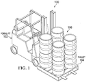
- FIG. 1 is an illustration of an illustrative scene 100 in which a forklift 102 transporting a pallet 104 on which a load 106 including one or more objects is positioned.
- the load in this case is a set of barrels.
- volume of the load 106 may be measured.
- the load 106 may include one or more objects that are the same or different shapes.
- Each object of the load 106 may include a machine readable indicia, such as a barcode, disposed on the outside thereof.
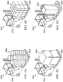
- FIGS. 2A-2D an illustration of illustrative scenes 200a-200d are shown that include forklifts 202a-202d that are transporting pallets 204a-204d on which different sized and shaped loads 206a-206d (collectively 206 ) are positioned.
- the loads 206 include a variety of different shaped objects, including barrels 206a , small boxes 206b , large boxes 206c , and equipment 206d. It should be understood that the objects may be any sized and shaped objects that are typically transported on pallets, as understood in the art.
- An entrance window 306 may be defined by the frame 302 or portions of a wall (not shown) that a forklift or other vehicle may move a pallet with a load into and out of the measuring station 300.
- the entrance window 306 may be equipped with a safety sensor (e.g., optical sensor) that identifies when something or somebody crosses into the entrance window 306 , which, if sensed, may cause measurement operations to be ceased.
- a safety barrier such as a gate or arm, may be positioned to prevent something or someone cross into the entrance window 306 , thereby preventing injury to an operator or damage to an object.
- a sense signal in response to a sensor (not shown) sensing that someone or something crossed into the entrance window 306 , a sense signal may be generated and communicated to a computing device, such as workstation 314 (described hereinbelow), to cause the computing device to communicate a stop signal (or "go home” signal) to instruct the UAV to stop imaging by flying to a landing area.
- a computing device such as workstation 314 (described hereinbelow) to cause the computing device to communicate a stop signal (or "go home” signal) to instruct the UAV to stop imaging by flying to a landing area.
- a ground pattern 308 may be disposed (e.g., painted, stamped, applied via an adhesive, etc.) on a floor 309 within the measuring station 300.
- the ground pattern 308 is shown to be a "bull's-eye," but other ground pattern may be utilized.
- the ground pattern 308 may have particular dimensions that may be utilized as reference dimensions when determining dimensions of an object or orienting an imaging device, such as a UAV.
- the measuring station 300 may further include one or more landing/takeoff and recharge areas 310a-310a (collectively 310 ) on which one or more UAVs 312a-312d (collectively 312 ) may be positioned while not being utilized to capture images of objects.
- the recharge areas may have electrical recharge capabilities for recharging the battery on the UAV(s) 312. If the batteries on the UAVs 312 are capable of 15 continuous minutes of flight for every hour of charge, for example, by maintaining at least four UAVs 312 within a measuring station 300 , a 24x7 continuous operation of UAVs 312 may be possible, thereby providing no downtime for performing volume dimensioning of loads on pallets.
- the recharge areas may be configured as one or more platforms.
- the recharge areas 310 may be configured with wireless recharge devices that are able to recharge a UAV wirelessly. Alternatively the recharge areas 310 may be contact chargers that match contacts on the UAVs 312.
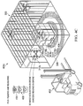
- a forklift 402 is shown to be moving a pallet 404 with a load 406 including multiple items toward the reading station 300.
- An indicator device 408 represented as a stoplight, is shown to be lighting a green light 410 , which indicates that the reading station 300 is available for loading with the pallet 404 on which the load 406 is positioned.
- the indicator device 408 may additionally and/or alternatively include an audible indicator that is used to give notice to the operator of the status (e.g., available to enter, caution, do not enter) of the reading station 300.
- the forklift 402 may cross the entrance window 308 to place the pallet 404 on the ground pattern 308 for measuring by a UAV.
- the appointed UAV or drone 312a may takeoff from a recharge area, localize and read a pallet identification barcode, which is today performed manually by a designed operator, may take 3D pictures or images of a scene (i.e., the load 406 ) and communicate the images to an external computing device (e.g., workstation outside the reading station) for a volume calculation to be performed and storage of the images.
- a pallet identification barcode which is today performed manually by a designed operator
- an external computing device e.g., workstation outside the reading station
- the forklift 402 with the already measured load 406 on the pallet 404 exits the reading station 300 , and the indicator 406 turns on the indicator light 410 , which is green, to notify the operator or another operator that the reading station 300 is ready to start another measurement task.
- the reading station 500 may include a frame 502 , such as a cage or room, on which markers 504a-504k (collectively 504 ), such as illumination devices (e.g., LEDs or LED bars, RF antenna, fibre optic light, etc.), may be positioned to provide points of reference within the reading station 500.
- the markers 504 may alternatively be passive visual elements (e.g., painted crosses), but the use of active reference points (e.g., LEDs) allows for the reference points to be selectively turned on and off.
- the UAV 510 may include one video system for navigation and one for 3D acquisition, although both functions may be performed by a single video capture system.
- the UAV 510 may also be configured with surveillance functionality (e.g., separate camera and/or sensor) that identifies and avoids humans.
- an operator may train the UAV 510 to locate each of the measuring points 506.
- the UAV 510 may view a plurality of markers 504 using a measuring camera used to measure objects or a separate camera that is used for positioning purposes.
- the training may occur by the operator defining distances d1-dn of desired measuring points 506 that the UAV 510 is to fly to take measurements or the UAV 510 may measuring the distances d1-dn when an operator manually positions, via remote control, the UAV 510 at desired measuring points 506.
- the markers 504 may be positioned at additional and/or other locations (e.g., floor and/or ceiling) within the reading station 500.
- the camera may be a time-of-flight camera that is configured to measure distances from the UAV 510 to the markers 504. While determining the measuring points 506 in an accurate manner is helpful, it should be understood that precise location is not critical as the use of a 3D camera and/or other image processing techniques may provide for determining accurate volume dimensions if the UAV 510 captures the images from points that are not precisely at the measuring points 506.
- a "real time flight plan" may navigate the UAV 510 through the measure points 506 , and be adaptable based on feedback from a remote computing device (e.g., workstation) that performs 3D reconstruction.
- the UAV 510 may be configured with multiple communications channels, one for navigation and one for data communication. Feedback positioning in 3-dimensions (longitude, latitude, altitude) may be provided to the UAV 510 to reposition the UAV 510 and/or adjust a measuring point 506.
- feedback and control instructions may include, "30cm closer and repeat the image acquisitions” or “add 2 measuring points in the flight plan and repeat the image acquisitions.” It should be understood that the control signals may have alternative coding (e.g., X-30, Y+4, Z+2; RepAcq).
- a flow diagram of an illustrative process 600 for using an autonomous unmanned aerial vehicle measuring volume of objects on a pallet is shown.
- the process 600 is represented by two sides, a client side 602 (e.g., UAV) and a server side 604 (e.g., remote processing unit, such as a workstation).
- a 3D vision camera on board the UAV may be configured to communicate wirelessly in real-time with an external workstation, for example.
- the UAV is considered to be on the client side 602
- the workstation may be a server on the server side.
- the process 600 may start at step 606 , where the UAV takes off, and at step 608 starts an on-board autonomous navigation system.
- a path detection may be performed for autonomous navigation purposes. The path detection may be performed by detecting an extent of the reading station and plan a flight or navigation path.
- barcode identification may be performed over each measuring point. In addition, other symbols, such as hazmat, may be captured and identified at each measuring point.
- collected data, 2D and/or 3D may be communicated the server perform barcode identification to assign the correct ID to the product perform.
- flight navigation of the UAV may be performed by the UAV flying via each of the measuring points according to a flight plan, as previously described.
- image data such as 3D image data
- the processing may be performed to determine volume dimensions, machine readable indicia information, and possible feedback for adjusting the flight path of the UAV, providing a location of missing data to the UAV, or providing other commands (e.g., scan again) to the UAV.
- a 3D image may be generated using techniques, as understood in the art.
- the server side 604 may perform the following steps.
- a depth image may be received.
- Each received depth map may be aligned to the a current 3D model and fused using a KinectFusion-like framework at step 620.
- Multi-resolution Truncated Signed Distance Function (TSDF, a volumetric representation of a scene used for integration of multiple depth images coming from different viewpoints) extensions may be deployed for reduced memory footprint, as well as advanced tracking algorithms based on RGB-D, as understood in the art, and inertial measurement (IMU) data, if available.
- TSDF Multi-resolution Truncated Signed Distance Function
- IMU inertial measurement
- Volume dimensions measurements may be performed by integrating a triangular mesh along the ground plane at step 630.
- a 3D rendering may also be performed at step 630.
- a determination may be made as to whether all paths or measuring points have been performed. If not, then the process may be return to step 612 to perform indicia (e.g., barcode) identification. If so, then the process 600 may be passed to the feedback manager at step 628 on the server side 604 , as previously described.
- indicia e.g., barcode
- the process may continue to step 634 , where a determination may be made as to whether the feedback does not have adjustment commands (i.e., readings are satisfactory) as received via a communications network from the feedback manager 628 of the server side 604. If not, then the process may return back to step 610 to perform path detection to position the UAV at a measuring point. Alternatively, if the feedback is indicative that the volume dimensions measurements are satisfactory, then the process 600 may restart reading a new pallet at step 608. Alternatively, the process may instruct the UAV to return to a recharging station while a new pallet is delivered to the measuring station.
- adjustment commands i.e., readings are satisfactory
- FIG. 7 is a flow diagram of another illustrative process 700 for using an autonomous unmanned aerial vehicle measuring volume of objects on a pallet.
- the process 700 may include flying a UAV to measuring points around an object within a defined area at step 702.
- images of the object may be captured by the UAV at each of the measuring points.
- the captured images may be communicated by the UAV to a computing device remotely positioned from the UAV at step 706.
- Volume dimensions of the object may be computed based on the captured images at step 708.
- the volume dimensions of the object may be presented. In presenting the volume dimensions, the volume dimensions may be presented to a user via an electronic display. Alternatively, the volume dimensions may be electronically presented to another system that uses the volume dimensions for logistics and/or shipping purposes.
- Embodiments implemented in computer software may be implemented in software, firmware, middleware, microcode, hardware description languages, or any combination thereof.
- a code segment or machine-executable instructions may represent a procedure, a function, a subprogram, a program, a routine, a subroutine, a module, a software package, a class, or any combination of instructions, data structures, or program statements.
- a code segment may be coupled to another code segment or a hardware circuit by passing and/or receiving information, data, arguments, parameters, or memory contents.
- Information, arguments, parameters, data, etc. may be passed, forwarded, or transmitted via any suitable means including memory sharing, message passing, token passing, network transmission, etc.
- the functions When implemented in software, the functions may be stored as one or more instructions or code on a non-transitory computer-readable or processor-readable storage medium.
- the steps of a method or algorithm disclosed herein may be embodied in a processor-executable software module which may reside on a computer-readable or processor-readable storage medium.
- a non-transitory computer-readable or processor-readable media includes both computer storage media and tangible storage media that facilitate transfer of a computer program from one place to another.
- a non-transitory processor-readable storage media may be any available media that may be accessed by a computer.
- non-transitory processor-readable media may comprise RAM, ROM, EEPROM, CD-ROM or other optical disk storage, magnetic disk storage or other magnetic storage devices, or any other tangible storage medium that may be used to store desired program code in the form of instructions or data structures and that may be accessed by a computer or processor.
- Disk and disc include compact disc (CD), laser disc, optical disc, digital versatile disc (DVD), floppy disk, and Blu-ray disc where disks usually reproduce data magnetically, while discs reproduce data optically with lasers. Combinations of the above should also be included within the scope of computer-readable media.
- the operations of a method or algorithm may reside as one or any combination or set of codes and/or instructions on a non-transitory processor-readable medium and/or computer-readable medium, which may be incorporated into a computer program product.
Landscapes
- Engineering & Computer Science (AREA)
- Physics & Mathematics (AREA)
- General Physics & Mathematics (AREA)
- Computer Vision & Pattern Recognition (AREA)
- Theoretical Computer Science (AREA)
- Aviation & Aerospace Engineering (AREA)
- Geometry (AREA)
- Mechanical Engineering (AREA)
- Transportation (AREA)
- Power Engineering (AREA)
- Radar, Positioning & Navigation (AREA)
- Remote Sensing (AREA)
- Automation & Control Theory (AREA)
- Control Of Position, Course, Altitude, Or Attitude Of Moving Bodies (AREA)
- Length Measuring Devices By Optical Means (AREA)
Abstract
Description
- Typical systems developed for pallet volume dimensioning (volume measuring of cargo positioned on the pallets) are designed in order to work on multiple static objects placed under a laser measurement system. Very precise measurements can be achieved by increasing scan time of the objects and by using multiple laser scanners or cameras. Consolidated solutions available in the market have limitations, which are mainly related to maintenance. Maintenance of pallet volume dimensioning solutions generally includes laser degradations, head replacements, moving parts maintenance, electromechanical driver replacements and maintenance, and so forth.
- Another problem with existing pallet volume dimensioning systems are bulky sizes of the systems, which include large frames, drivers, motors, extender arms with multiple laser scanners or cameras, and other moving parts that may wear out. In some cases, the frames are moved during a scanning process. Moreover, existing systems are fairly expensive for the customer to purchase and maintain. As an example, it is estimated that about $50,000 or more is needed simply to perform the volume dimensioning measurements, which does not include weighing the cargo and reading barcodes affixed to the cargo.
- Accordingly, there is a need to reduce cost and size of pallet volume dimensioning systems and maintenance thereof, while maintaining or improving accuracy and functionality.
- To reduce cost, complexity, and maintenance of pallet volume measurement systems, an autonomous unmanned aerial vehicle (UAV) or drone configured to performing measurements and optionally read machine readable indicia (e.g., barcodes, QR codes, text, etc.) and other identifiers (e.g., hazmat symbols) may be utilized. The UAV may be configured with minimal computational power and simplistic positioning capabilities, thereby reducing complexity and cost of the UAV. In an embodiment, the UAV may be configured with a 3D or stereoscopic camera so as to capture 3D images to enable accurate measurements of objects on a pallet to be taken.
- One embodiment of a method for measuring volume dimensions of objects may include flying a UAV to measuring points around an object within a defined area. Images of the object may be captured by the UAV at each of the measuring points. The captured images may be communicated by the UAV to a computing device remotely positioned from the UAV. Volume dimensions of the object may be computed based on the captured images. The volume dimensions of the object may be presented. In presenting the volume dimensions, the volume dimensions may be presented to a user via an electronic display.
- One embodiment of a system for measuring volume dimensions of objects may include a defined area within which a load on a pallet is to be imaged for determining volume dimensions. A computing device, such as a workstation may be utilized. A UAV may be configured to fly to measuring points around an object within the defined area. The UAV may include a (i) camera, (ii) processing unit, and (iii) input/output (I/O) unit. The UAV may be configured to capture images of the object using the camera at each of the measuring points, and communicate the captured images via the I/O unit to the computing device remotely positioned from the UAV. The computing device may be configured to compute volume dimensions of the object based on the captured images, and present the volume dimensions of the object.
- Illustrative embodiments of the present invention are described in detail below with reference to the attached drawing figures, which are incorporated by reference herein and wherein:
-
FIG. 1 is an illustration of an illustrative scene in which a forldift transporting a pallet on which a load is positioned; -
FIGS. 2A-2D is an illustration of an illustrative set of forklifts transporting pallets on which different sized and shaped loads are positioned; -
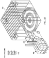
FIG. 3 is an illustration of an illustrative reading station in which pallets with loads may be positioned for an autonomous unmanned aerial vehicle (UAV) (e.g., drone) to measure volume dimensioning of the loads on the pallets is shown. -
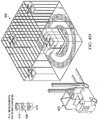
FIGS. 4A-4E are illustrations of the reading station ofFIG. 3 that show a process for loading, reading, and unloading a pallet with a load to be read by the UAV; -
FIGS. 5A and 5B are illustrations of an illustrative reading station showing positions within which an autonomous unmanned aerial vehicle may be positioned during a training session and thereafter automatically position itself for measuring volume of objects on a pallet; -
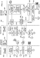
FIG. 6 is a flow diagram of an illustrative process for using an autonomous unmanned aerial vehicle measuring volume of objects on a pallet; and -
FIG. 7 is a flow diagram of another illustrative process for using an autonomous unmanned aerial vehicle measuring volume of objects on a pallet. - With regard to
FIG. 1 is an illustration of anillustrative scene 100 in which aforklift 102 transporting a pallet 104 on which aload 106 including one or more objects is positioned. The load in this case is a set of barrels. For shipping and logistics purposes, volume of theload 106 may be measured. Theload 106 may include one or more objects that are the same or different shapes. Each object of theload 106 may include a machine readable indicia, such as a barcode, disposed on the outside thereof. - With regard to
FIGS. 2A-2D , an illustration ofillustrative scenes 200a-200d are shown that includeforklifts 202a-202d that are transportingpallets 204a-204d on which different sized andshaped loads 206a-206d (collectively 206) are positioned. The loads 206 include a variety of different shaped objects, includingbarrels 206a,small boxes 206b,large boxes 206c, andequipment 206d. It should be understood that the objects may be any sized and shaped objects that are typically transported on pallets, as understood in the art. - With regard to
FIG. 3 is an illustration of anillustrative reading station 300 in which pallets with loads may be positioned for an autonomous unmanned aerial vehicle (UAV) (e.g., drone) to measure volume dimensioning of the loads on the pallets is shown. Thereading station 300 is a defined area in which the loads may be positioned for measuring. Thereading station 300 may be a room. In an embodiment, themeasuring station 300 may include aframe 302 inclusive of a plurality of walls, such as threewalls measuring station 300 may further include aceiling 304d. Anentrance window 306 may be defined by theframe 302 or portions of a wall (not shown) that a forklift or other vehicle may move a pallet with a load into and out of themeasuring station 300. Theentrance window 306 may be equipped with a safety sensor (e.g., optical sensor) that identifies when something or somebody crosses into theentrance window 306, which, if sensed, may cause measurement operations to be ceased. In an alternative embodiment, a safety barrier, such as a gate or arm, may be positioned to prevent something or someone cross into theentrance window 306, thereby preventing injury to an operator or damage to an object. In an embodiment, in response to a sensor (not shown) sensing that someone or something crossed into theentrance window 306, a sense signal may be generated and communicated to a computing device, such as workstation 314 (described hereinbelow), to cause the computing device to communicate a stop signal (or "go home" signal) to instruct the UAV to stop imaging by flying to a landing area. - In an embodiment, a
ground pattern 308 may be disposed (e.g., painted, stamped, applied via an adhesive, etc.) on afloor 309 within themeasuring station 300. Theground pattern 308 is shown to be a "bull's-eye," but other ground pattern may be utilized. In an embodiment, theground pattern 308 may have particular dimensions that may be utilized as reference dimensions when determining dimensions of an object or orienting an imaging device, such as a UAV. - The
measuring station 300 may further include one or more landing/takeoff andrecharge areas 310a-310a (collectively 310) on which one ormore UAVs 312a-312d (collectively 312) may be positioned while not being utilized to capture images of objects. The recharge areas may have electrical recharge capabilities for recharging the battery on the UAV(s) 312. If the batteries on the UAVs 312 are capable of 15 continuous minutes of flight for every hour of charge, for example, by maintaining at least four UAVs 312 within ameasuring station 300, a 24x7 continuous operation of UAVs 312 may be possible, thereby providing no downtime for performing volume dimensioning of loads on pallets.. In an embodiment, the recharge areas may be configured as one or more platforms. The recharge areas 310 may be configured with wireless recharge devices that are able to recharge a UAV wirelessly. Alternatively the recharge areas 310 may be contact chargers that match contacts on the UAVs 312. - In an environment, and
external workstation 314 may be positioned outside of the measuringstation 300, and be configured to receive communications from the UAV(s) 312 via wired or wireless communications network. The wireless communications network may utilize a local communications protocol, such as Wi-Fi®, or any other communications protocol (e.g., wide area network (WAN)), as understood in the art. The UAV(s) 312 may be configured to communicate images being captured by a camera on the UAV(s) 312 via the communications network. In an alternative embodiment, the communications network may be a wired communications network, such as a fiber optic or power over fiber or wire. However, while the use of wire increases security, wire may present more complications in terms of the UAVs flying around loads. In an embodiment, the communicated data may be encrypted to increase security. - With regard to
FIGS. 4A-4E , illustrations that collectively show aprocess 400a-400e (collectively 400) for imaging a load in the readingstation 300 ofFIG. 3 by a UAV are shown. - As shown in
FIG. 4A , aforklift 402 is shown to be moving apallet 404 with aload 406 including multiple items toward the readingstation 300. Anindicator device 408, represented as a stoplight, is shown to be lighting agreen light 410, which indicates that the readingstation 300 is available for loading with thepallet 404 on which theload 406 is positioned. Theindicator device 408 may additionally and/or alternatively include an audible indicator that is used to give notice to the operator of the status (e.g., available to enter, caution, do not enter) of the readingstation 300. Theforklift 402 may cross theentrance window 308 to place thepallet 404 on theground pattern 308 for measuring by a UAV. - As shown in
FIG. 4B , thepallet 404 with theload 406 is shown to be loaded in the readingstation 300 with theforklift 402 backed out of the readingstation 300. The readingstation 300 at this point is loaded and ready to start a measuring phase. Theindicator device 408 at this point has anindicator light 412, in this case a yellow light, turned on to notify an operator of theforklift 402 to go slow or otherwise be cautious as a measuring process is soon to begin. - As shown in
FIG. 4C , anactive step 400c may enable the UAV 412a to perform reading of machine readable indicia (e.g., barcodes) 416a-416d (collectively 416) and volume measuring of a theload 406. While the UAV 412a is in operation, theindicator device 408 turn on anindicator light 414, in this case a red light, to notify the operator to not enter the readingstation 300. As will further be described herein, to perform the reading and imaging, the appointed UAV ordrone 312a may takeoff from a recharge area, localize and read a pallet identification barcode, which is today performed manually by a designed operator, may take 3D pictures or images of a scene (i.e., the load 406) and communicate the images to an external computing device (e.g., workstation outside the reading station) for a volume calculation to be performed and storage of the images. - With regard to
FIG. 4D , after the active phase is complete, theUAV 312a flies back and lands on the recharge area. The operator of theforklift 402 is enabled to enter inside the readingstation 300 to remove thepallet 404 with theload 406. Theindicator device 406 is shown to be illuminating the indicator light 410 to indicate to the operator of theforklift 402 that it is safe to enter the readingstation 300. - With regard to
FIG. 4E , theforklift 402 with the already measuredload 406 on thepallet 404 exits the readingstation 300, and theindicator 406 turns on theindicator light 410, which is green, to notify the operator or another operator that the readingstation 300 is ready to start another measurement task. - With regard to
FIGS. 5A and 5B , illustrations of anillustrative reading station 500 in which an autonomous unmanned aerial vehicle may be trained during a training session and thereafter automatically position itself at measuring points for measuring volume of objects on a pallet are shown. The readingstation 500 may include aframe 502, such as a cage or room, on whichmarkers 504a-504k (collectively 504), such as illumination devices (e.g., LEDs or LED bars, RF antenna, fibre optic light, etc.), may be positioned to provide points of reference within the readingstation 500. The markers 504 may alternatively be passive visual elements (e.g., painted crosses), but the use of active reference points (e.g., LEDs) allows for the reference points to be selectively turned on and off. - In an embodiment, a set of measuring
points 506a-506h (collectively 506) may be defined around a maximum volume ofmeasure 508 representative of a maximum sized load on a pallet that may be measured using an autonomous unmannedaerial vehicle 510. The use of the maximum volume ofmeasure 508 prevents theUAV 510 from hitting a load during operations. The measuring points 506 may be positioned at substantially the same or different altitudes and substantially equal or different angular distances around a center point of the maximum volume ofmeasure 508. Asafe flight area 512 may also be specified that limits theUAV 510 from entering so as to provide an extra level of safety to people and objects that may be within the readingstation 500 during operations. TheUAV 510 may include one video system for navigation and one for 3D acquisition, although both functions may be performed by a single video capture system. TheUAV 510 may also be configured with surveillance functionality (e.g., separate camera and/or sensor) that identifies and avoids humans. - In operation, an operator may train the
UAV 510 to locate each of the measuring points 506. In the training, theUAV 510 may view a plurality of markers 504 using a measuring camera used to measure objects or a separate camera that is used for positioning purposes. The training may occur by the operator defining distances d1-dn of desired measuring points 506 that theUAV 510 is to fly to take measurements or theUAV 510 may measuring the distances d1-dn when an operator manually positions, via remote control, theUAV 510 at desired measuring points 506. It should be understood that the markers 504 may be positioned at additional and/or other locations (e.g., floor and/or ceiling) within the readingstation 500. The camera may be a time-of-flight camera that is configured to measure distances from theUAV 510 to the markers 504. While determining the measuring points 506 in an accurate manner is helpful, it should be understood that precise location is not critical as the use of a 3D camera and/or other image processing techniques may provide for determining accurate volume dimensions if theUAV 510 captures the images from points that are not precisely at the measuring points 506. - In the training session, the operator may be able to define a flight path via each of the measuring points 506 that the
UAV 510 is to fly while measuring a load. The training session may utilize a "reference parcel" of known measurements for calibration purposes. In an embodiment, theUAV 510 or remote workstation that may be configured to control the flight path may be configured to automatically determine flight path of one or more UAVs that are to be used within the readingstation 500 to minimize distances. In particular, the flight plan may include of a set of measuring points 506 to be sequentially reached, where each of the measuring points 506 may be uniquely defined by distances d1-dn from the markers 504. At each of the measuring points 506, the drone may perform hovering while performing a 3D image acquisition. It should be understood that different measure points 506 are associated with a different set of distances and may utilize the same or different markers 504 in determining the distances that are used to define the measuring points 506. - Once the flight path is defined for the
UAV 510, theUAV 510 may be able to autonomously navigate the "measuring area" via the measuring points 506 by relying solely on visual information of the markers 504 acquired by a camera (e.g., 3D camera) on theUAV 510. The flight plan may be stored in a memory of theUAV 510. As shown inFIG. 5B , theUAV 510 may measure five distances d1, d8, d7, d6, and d5 from fiverespective markers UAV 510 is to capture an image of the load being measured. It should be understood that more or fewer markers may be used to determine each measuring point 506. In an embodiment, a "real time flight plan" (RFP) may navigate theUAV 510 through the measure points 506, and be adaptable based on feedback from a remote computing device (e.g., workstation) that performs 3D reconstruction. In an embodiment, theUAV 510 may be configured with multiple communications channels, one for navigation and one for data communication. Feedback positioning in 3-dimensions (longitude, latitude, altitude) may be provided to theUAV 510 to reposition theUAV 510 and/or adjust a measuring point 506. As an example, feedback and control instructions may include, "30cm closer and repeat the image acquisitions" or "add 2 measuring points in the flight plan and repeat the image acquisitions." It should be understood that the control signals may have alternative coding (e.g., X-30, Y+4, Z+2; RepAcq). - As a result of using the markers 504 that may be measured during flight by the
UAV 510, high-end sensors and processing power that is common to UAVs for performing global positioning system (GPS) measurements, simultaneous localization and mapping (SLAM), or other positioning techniques and technologies, may be avoided, thereby reducing the cost and maintenance of theUAV 510. In capturing the images of the load, the images may be stored or not stored on theUAV 510, and if not stored, the images may be transmitted to the remote computing device for storage and processing thereby. By not storing the images, reduced weight and power usage on theUAV 510 may be achieved, and increased security may also be achieved as possible damage or theft of the images may be reduced. - With regard to
FIG. 6 , a flow diagram of anillustrative process 600 for using an autonomous unmanned aerial vehicle measuring volume of objects on a pallet is shown. To employ theprocess 600, theprocess 600 is represented by two sides, a client side 602 (e.g., UAV) and a server side 604 (e.g., remote processing unit, such as a workstation). In an embodiment, a 3D vision camera on board the UAV may be configured to communicate wirelessly in real-time with an external workstation, for example. The UAV is considered to be on theclient side 602, and the workstation may be a server on the server side. - The
process 600 may start atstep 606, where the UAV takes off, and atstep 608 starts an on-board autonomous navigation system. Atstep 610, a path detection may be performed for autonomous navigation purposes. The path detection may be performed by detecting an extent of the reading station and plan a flight or navigation path. Atstep 612, barcode identification may be performed over each measuring point. In addition, other symbols, such as hazmat, may be captured and identified at each measuring point. At each measuring point, collected data, 2D and/or 3D, may be communicated the server perform barcode identification to assign the correct ID to the product perform. Atstep 614, flight navigation of the UAV may be performed by the UAV flying via each of the measuring points according to a flight plan, as previously described. Atstep 616, image data, such as 3D image data, may be communicated wirelessly to a remote processing unit for processing. The processing may be performed to determine volume dimensions, machine readable indicia information, and possible feedback for adjusting the flight path of the UAV, providing a location of missing data to the UAV, or providing other commands (e.g., scan again) to the UAV. If 2D images are captured, a 3D image may be generated using techniques, as understood in the art. - More specifically, in
step 616, theserver side 604 may perform the following steps. Atstep 618, a depth image may be received. Each received depth map may be aligned to the a current 3D model and fused using a KinectFusion-like framework atstep 620. Multi-resolution Truncated Signed Distance Function (TSDF, a volumetric representation of a scene used for integration of multiple depth images coming from different viewpoints) extensions may be deployed for reduced memory footprint, as well as advanced tracking algorithms based on RGB-D, as understood in the art, and inertial measurement (IMU) data, if available. Moreover, atstep 622, after each fusion, the model may raycast from the last estimate UAV's position, which provides an operator with instant feedback on the operation. Optionally, Marching Cubes can be performed on a TSDF volume to show an incremental 3D reconstruction. Atstep 624, a determination may be made as to whether the UAV has completed the flight path. If not, then the process may return to step 618. Alternatively if the flight path via the measuring points is complete, atstep 626, theprocess 600 may perform automated as well as human inspections both on the final TSDF volume and on the 3D reconstruction. A quality measurement or other quality feedback may be communicated to a feedback manager atstep 628. If any information is determined to be missing, both quality or precision, new data acquisition may be requested. - Volume dimensions measurements may be performed by integrating a triangular mesh along the ground plane at
step 630. A 3D rendering may also be performed atstep 630. Atstep 632 on theclient side 602, a determination may be made as to whether all paths or measuring points have been performed. If not, then the process may be return to step 612 to perform indicia (e.g., barcode) identification. If so, then theprocess 600 may be passed to the feedback manager atstep 628 on theserver side 604, as previously described. In addition, on theclient side 602, the process may continue to step 634, where a determination may be made as to whether the feedback does not have adjustment commands (i.e., readings are satisfactory) as received via a communications network from thefeedback manager 628 of theserver side 604. If not, then the process may return back to step 610 to perform path detection to position the UAV at a measuring point. Alternatively, if the feedback is indicative that the volume dimensions measurements are satisfactory, then theprocess 600 may restart reading a new pallet atstep 608. Alternatively, the process may instruct the UAV to return to a recharging station while a new pallet is delivered to the measuring station. - With regard to
FIG. 7 is a flow diagram of anotherillustrative process 700 for using an autonomous unmanned aerial vehicle measuring volume of objects on a pallet. Theprocess 700 may include flying a UAV to measuring points around an object within a defined area atstep 702. Atstep 704, images of the object may be captured by the UAV at each of the measuring points. The captured images may be communicated by the UAV to a computing device remotely positioned from the UAV atstep 706. Volume dimensions of the object may be computed based on the captured images atstep 708. Atstep 710, the volume dimensions of the object may be presented. In presenting the volume dimensions, the volume dimensions may be presented to a user via an electronic display. Alternatively, the volume dimensions may be electronically presented to another system that uses the volume dimensions for logistics and/or shipping purposes. - The foregoing method descriptions and the process flow diagrams are provided merely as illustrative examples and are not intended to require or imply that the steps of the various embodiments must be performed in the order presented. As will be appreciated by one of skill in the art the steps in the foregoing embodiments may be performed in any order. Words such as "then," "next," etc. are not intended to limit the order of the steps; these words are simply used to guide the reader through the description of the methods. Although process flow diagrams may describe the operations as a sequential process, many of the operations can be performed in parallel or concurrently. In addition, the order of the operations may be rearranged. A process may correspond to a method, a function, a procedure, a subroutine, a subprogram, etc. When a process corresponds to a function, its termination may correspond to a return of the function to the calling function or the main function.
- The various illustrative logical blocks, modules, circuits, and algorithm steps described in connection with the embodiments disclosed herein may be implemented as electronic hardware, computer software, or combinations of both. To clearly illustrate this interchangeability of hardware and software, various illustrative components, blocks, modules, circuits, and steps have been described above generally in terms of their functionality. Whether such functionality is implemented as hardware or software depends upon the particular application and design constraints imposed on the overall system. Skilled artisans may implement the described functionality in varying ways for each particular application, but such implementation decisions should not be interpreted as causing a departure from the scope of the principles of the present invention.
- Embodiments implemented in computer software may be implemented in software, firmware, middleware, microcode, hardware description languages, or any combination thereof. A code segment or machine-executable instructions may represent a procedure, a function, a subprogram, a program, a routine, a subroutine, a module, a software package, a class, or any combination of instructions, data structures, or program statements. A code segment may be coupled to another code segment or a hardware circuit by passing and/or receiving information, data, arguments, parameters, or memory contents. Information, arguments, parameters, data, etc. may be passed, forwarded, or transmitted via any suitable means including memory sharing, message passing, token passing, network transmission, etc.
- The actual software code or specialized control hardware used to implement these systems and methods is not limiting of the invention. Thus, the operation and behavior of the systems and methods were described without reference to the specific software code being understood that software and control hardware can be designed to implement the systems and methods based on the description herein.
- When implemented in software, the functions may be stored as one or more instructions or code on a non-transitory computer-readable or processor-readable storage medium. The steps of a method or algorithm disclosed herein may be embodied in a processor-executable software module which may reside on a computer-readable or processor-readable storage medium. A non-transitory computer-readable or processor-readable media includes both computer storage media and tangible storage media that facilitate transfer of a computer program from one place to another. A non-transitory processor-readable storage media may be any available media that may be accessed by a computer. By way of example, and not limitation, such non-transitory processor-readable media may comprise RAM, ROM, EEPROM, CD-ROM or other optical disk storage, magnetic disk storage or other magnetic storage devices, or any other tangible storage medium that may be used to store desired program code in the form of instructions or data structures and that may be accessed by a computer or processor. Disk and disc, as used herein, include compact disc (CD), laser disc, optical disc, digital versatile disc (DVD), floppy disk, and Blu-ray disc where disks usually reproduce data magnetically, while discs reproduce data optically with lasers. Combinations of the above should also be included within the scope of computer-readable media. Additionally, the operations of a method or algorithm may reside as one or any combination or set of codes and/or instructions on a non-transitory processor-readable medium and/or computer-readable medium, which may be incorporated into a computer program product.
- The preceding description of the disclosed embodiments is provided to enable any person skilled in the art to make or use the present invention. Various modifications to these embodiments will be readily apparent to those skilled in the art, and the generic principles defined herein may be applied to other embodiments without departing from the spirit or scope of the invention. Thus, the present invention is not intended to be limited to the embodiments shown herein but is to be accorded the widest scope consistent with the following claims and the principles and novel features disclosed herein.
The previous description is of a preferred embodiment for implementing the invention, and the scope of the invention should not necessarily be limited by this description. The scope of the present invention is instead defined by the following claims.
Further embodiments are given in the following paragraphs: - 1. A method for measuring volume dimensions of objects, said method comprising: flying an autonomous unmanned aerial vehicle (UAV) to measuring points around an object within a defined area; capturing, by the UAV, images of the object at each of the measuring points; communicating, by the UAV, the captured images to a computing device remotely positioned from the UAV; computing, by the computing device, volume dimensions of the object based on the captured images; and presenting the volume dimensions of the object.
- 2. The method according to
embodiment 1, wherein capturing the images includes capturing three-dimensional (3D) images. - 3. The method according to
embodiment 1, further comprising establishing the measuring points based on distances from a plurality of markers positioned within the defined area. - 4. The method according to
embodiment 1, wherein flying the UAV includes flying the UAV within a cage including at least three walls. - 5. The method according to
embodiment 1, wherein flying the UAV to measuring points includes: viewing, by a camera on the UAV, a plurality of markers within the defined area; measuring, by the UAV, distances from the respective markers; and moving, by the UAV, position of the UAV until the UAV flies via each of the measuring points based on the measured distances from the respective markers. - 6. The method according to embodiment 5, further comprising causing the markers to illuminate to enable the UAV to measure distances from the illuminated markers.
- 7. The method according to
embodiment 1, further comprising: after capturing the images of the object, landing the UAV on a charger station within the defined area; and recharging a battery on the UAV by the charger station while the UAV is positioned on the charger station. - 8. The method according to embodiment 7, further comprising: generating a notification prior to initiating flight of the UAV, the notification used to notify an operator to exit the defined area; after the notification is generated, flying the UAV around the object; and after flying the UAV to the charger station, generating a different notification signal to notify the operator that it is safe to enter the defined area.
- 9. The method according to
embodiment 1, further comprising successively flying a plurality of UAVs within the defined area to capture images of the objects. - 10. The method according to
embodiment 1, wherein flying the UAV to each of the measuring points includes flying the UAV to the measuring points using a flight plan. - 11. The method according to embodiment 10, further comprising communicating, by the computing device, adjustments and/or additions to measuring points of the flight plan for capturing the images at the adjusted and/or additional measuring points.
- 12. The method according to
embodiment 1, further comprising imaging, by the UAV, a machine readable indicia associated with the object while flying around the object. - 13. The method according to
embodiment 1, further comprising: sensing that something or someone crosses an entrance window of the defined area; and in response to determining that the UAV is flying within the defined area, communicating a stop signal to the UAV to cause the UAV to stop imaging by flying to a landing area. - 14. The method according to
embodiment 1, further comprising identifying, by the computing device, a symbol on the object. - 15. A system for measuring volume dimensions of objects, said system comprising: a defined area within which a load on a pallet is to be imaged for determining volume dimensions; a computing device; and an autonomous unmanned aerial vehicle (UAV) configured to fly to measuring points around an object within the defined area, the UAV including a (i) camera, (ii) processing unit, and (iii) input/output (I/O) unit, and configured to: capture images of the object using the camera at each of the measuring points; and communicate the captured images via the I/O unit to the computing device remotely positioned from the UAV to: compute volume dimensions of the object based on the captured images; and present the volume dimensions of the object.
- 16. The system according to embodiment 15, wherein the camera of said UAV is a 3D camera configured to capture 3D images.
- 17. The system according to embodiment 15, wherein the processing unit of said UAV is configured to record a plurality of measuring points based on distances from a plurality of markers positioned within the defined area.
- 18. The system according to embodiment 15, wherein said defined area includes at least three walls.
- 19. The system according to claim 15, wherein said UAV, in flying to measuring points, is configured to: viewing, by the camera, a plurality of markers within said defined area; measure, by the processing unit, distances from the respective markers; and move, via a flight path, position of the UAV until the UAV flies via each of the measuring points based on the measured distances from the respective markers.
- 20. The system according to claim 19, wherein the markers are configured to illuminate to enable the UAV to measure distances from the illuminated markers.
- 21. The system according to embodiment 15, wherein the processing unit of the UAV is further configured to land the UAV on a charger station within the defined area after capturing the images of the object; and wherein a battery on the UAV is charged by the charger station while the UAV is positioned on the charger station.
- 22. The system according to embodiment 21, further comprising: a notification device configured to generate a notification prior to initiating flight of the UAV, whereby the notification notifies an operator to exit the defined area; wherein said computing device, after the notification is generated, is configured to communicate a signal to the UAV to initiate fly around the object; and after flying the UAV to the charger station, said notification device being configured to generate a different notification signal to notify the operator that it is safe to enter the defined area.
- 23. The system according to embodiment 15, further comprising a plurality of UAVs that said computing device is configured to successively control flying within the defined area to capture images of the objects.
- 24. The system according to embodiment 15, wherein the processing unit of the UAV is configured to fly the UAV to each of the measuring points using a flight plan stored in a memory of the UAV.
- 25. The system according to embodiment 24, wherein said computing device is further configured to communicate adjustments and/or additions to measuring points of the flight plan for the UAV to capture the images at the adjusted and/or additional measuring points.
- 26. The system according to embodiment 15, wherein the processing unit and camera of said UAV further are further configured to image a machine readable indicia associated with the object while flying around the object.
- 27. The system according to embodiment 15, further comprising a sensor at an entrance window of the defined area configured to sense that something or someone crosses the entrance window of the defined area, and, in response to the computing device receiving a sense signal indicative that something or someone crosses the entrance window while said UAV is flying within said defined area, communicating a stop signal to said UAV to cause said UAV to stop imaging by flying to a landing area.
- 28. The system according to embodiment 15, wherein said computing device is further configured to identify a symbol on the object.
Claims (15)
- A method for measuring volume dimensions of objects, characterized by:flying (702) an autonomous unmanned aerial vehicle (312, 412, 510) to measuring points (506) around an object within a defined area (300, 500);capturing (704), by the autonomous unmanned aerial vehicle (312, 412, 510), images of the object at each of the measuring points (506);communicating (706), by the autonomous unmanned aerial vehicle (312, 412, 510), the captured images to a computing device (314) remotely positioned from the autonomous unmanned aerial vehicle (312, 412, 510);computing (708), by the computing device (314), volume dimensions of the object based on the captured images; andpresenting (710) the volume dimensions of the object.
- The method according to claim 1, characterized in that capturing (704) the images includes capturing (704) three-dimensional (3D) images.
- The method according to claims 1 or 2, characterized by establishing the measuring points (506) based on distances from a plurality of markers (504) positioned within the defined area (300, 500).
- The method according to any one of the preceding claims, characterized in that flying the autonomous unmanned aerial vehicle (312, 412, 510) includes flying the autonomous unmanned aerial vehicle (312, 412, 510) within a cage (302, 502) including at least three walls (304).
- The method according to any one of the preceding claims, characterized in that flying the autonomous unmanned aerial vehicle (312, 412, 510) to measuring points (506) includes:viewing, by a camera on the autonomous unmanned aerial vehicle (312, 412, 510), a plurality of markers (504) within the defined area (300, 500);measuring, by the autonomous unmanned aerial vehicle (312, 412, 510), distances from the respective markers (504); andmoving, by the autonomous unmanned aerial vehicle (312, 412, 510), position of the autonomous unmanned aerial vehicle (312, 412, 510) until the autonomous unmanned aerial vehicle (312, 412, 510) flies via each of the measuring points (506) based on the measured distances from the respective markers (504).
- The method according to claim 5, characterized by causing the markers (504) to illuminate to enable the autonomous unmanned aerial vehicle (312, 412, 510) to measure distances from the illuminated markers (504).
- The method according to any one of the preceding claims, characterized by:after capturing (704) the images of the object, landing the autonomous unmanned aerial vehicle (312, 412, 510) on a charger station (310) within the defined area (300, 500); andrecharging a battery on the autonomous unmanned aerial vehicle (312, 412, 510) by the charger station (310) while the autonomous unmanned aerial vehicle (312, 412, 510) is positioned on the charger station (310).
- The method according to claim 7, characterized by:generating a notification prior to initiating flight of the autonomous unmanned aerial vehicle (312, 412, 510), the notification used to notify an operator to exit the defined area (300, 500);after the notification is generated, flying the autonomous unmanned aerial vehicle (312, 412, 510) around the object; andafter flying the autonomous unmanned aerial vehicle (312, 412, 510) to the charger station (310), generating a different notification signal to notify the operator that it is safe to enter the defined area (300, 500).
- The method according to any one of the preceding claims, characterized by successively flying a plurality of autonomous unmanned aerial vehicles (312, 412, 510) within the defined area (300, 500) to capture images of the objects.
- The method according to any one of the preceding claims, characterized in that flying the autonomous unmanned aerial vehicle (312, 412, 510) to each of the measuring points (506) includes flying the autonomous unmanned aerial vehicle (312, 412, 510) to the measuring points (506) using a flight plan.
- The method according to claim 10, characterized by communicating, by the computing device (314), adjustments and/or additions to measuring points (506) of the flight plan for capturing (704) the images at the adjusted and/or additional measuring points (506).
- The method according to any one of the preceding claims, characterized by imaging, by the autonomous unmanned aerial vehicle (312, 412, 510), a machine readable indicia associated with the object while flying around the object.
- The method according to any one of the preceding claims, characterized by:sensing that something or someone crosses an entrance window of the defined area (300, 500); andin response to determining that the autonomous unmanned aerial vehicle (312, 412, 510) is flying within the defined area (300, 500), communicating a stop signal to the autonomous unmanned aerial vehicle (312, 412, 510) to cause the autonomous unmanned aerial vehicle (312, 412, 510) to stop imaging by flying to a landing area.
- The method according to any one of the preceding claims, characterized by identifying, by the computing device (314), a symbol (416) on the object.
- A system for measuring volume dimensions of objects, characterized by:a defined area (300, 500) within which a load on a pallet is to be imaged for determining volume dimensions;a computing device (314); andan autonomous unmanned aerial vehicle (312, 412, 510) configured to fly to measuring points (506) around an object within the defined area (300, 500), the autonomous unmanned aerial vehicle (312, 412, 510) including a (i) camera, (ii) processing unit, and (iii) input/output (I/O) unit, and configured to:capture images of the object using the camera at each of the measuring points (506); andcommunicate the captured images via the I/O unit to the computing device (314) remotely positioned from the autonomous unmanned aerial vehicle (312, 412, 510) to:compute volume dimensions of the object based on the captured images; andpresent the volume dimensions of the object.
Applications Claiming Priority (1)
| Application Number | Priority Date | Filing Date | Title |
|---|---|---|---|
| US15/393,082 US11430148B2 (en) | 2016-12-28 | 2016-12-28 | Apparatus and method for pallet volume dimensioning through 3D vision capable unmanned aerial vehicles (UAV) |
Publications (1)
| Publication Number | Publication Date |
|---|---|
| EP3343510A1 true EP3343510A1 (en) | 2018-07-04 |
Family
ID=60990594
Family Applications (1)
| Application Number | Title | Priority Date | Filing Date |
|---|---|---|---|
| EP17210766.6A Withdrawn EP3343510A1 (en) | 2016-12-28 | 2017-12-27 | Apparatus and method for pallet volume dimensioning through 3d vision capable unmanned aerial vehicles (uav) |
Country Status (2)
| Country | Link |
|---|---|
| US (1) | US11430148B2 (en) |
| EP (1) | EP3343510A1 (en) |
Cited By (1)
| Publication number | Priority date | Publication date | Assignee | Title |
|---|---|---|---|---|
| WO2022106858A2 (en) | 2020-11-23 | 2022-05-27 | Botsandus Ltd | A method for measuring and analysing packages for storage |
Families Citing this family (15)
| Publication number | Priority date | Publication date | Assignee | Title |
|---|---|---|---|---|
| WO2017127711A1 (en) * | 2016-01-20 | 2017-07-27 | Ez3D, Llc | System and method for structural inspection and construction estimation using an unmanned aerial vehicle |
| JP6850245B2 (en) * | 2017-11-27 | 2021-03-31 | 五洋建設株式会社 | Quantity inspection system and quantity inspection method for the cargo of the ship's Tsuchikura |
| US12243001B1 (en) | 2018-10-09 | 2025-03-04 | Fida, Llc | Multilayered method and apparatus to facilitate the accurate calculation of freight density, area, and classification and provide recommendations to optimize shipping efficiency |
| US11379788B1 (en) | 2018-10-09 | 2022-07-05 | Fida, Llc | Multilayered method and apparatus to facilitate the accurate calculation of freight density, area, and classification and provide recommendations to optimize shipping efficiency |
| CN110706273B (en) * | 2019-08-21 | 2023-04-21 | 成都携恩科技有限公司 | Real-time collapse area measurement method based on unmanned aerial vehicle |
| US11703864B2 (en) * | 2020-02-13 | 2023-07-18 | Skydio, Inc. | Scanning structures via unmanned aerial vehicles |
| KR102316817B1 (en) | 2021-03-04 | 2021-10-25 | 주식회사 파블로항공 | Autonomous vehicle for handling goods in cooperation with unmanned aerial vehicle and method thereof |
| US20230073587A1 (en) * | 2021-09-09 | 2023-03-09 | The Boeing Company | Automated volumetric image capture of an object to support general visual inspection |
| US12559330B2 (en) * | 2022-11-15 | 2026-02-24 | Hand Held Products, Inc. | Loading operation monitoring apparatus and method of using the same |
| US12548258B2 (en) * | 2022-11-15 | 2026-02-10 | Nvidia Corporation | Techniques for training a machine learning model to reconstruct different three-dimensional scenes |
| US12548234B2 (en) | 2022-11-15 | 2026-02-10 | Nvidia Corporation | Techniques for fine-tuning a machine learning model to reconstruct a three-dimensional scene |
| US11655057B1 (en) * | 2022-12-22 | 2023-05-23 | The Adt Security Corporation | Mounts for unmanned aerial vehicles |
| WO2025101230A2 (en) * | 2023-06-15 | 2025-05-15 | Wing Aviation Llc | Initial location determination of uncrewed aerial vehicles from uncalibrated location observations |
| US12571646B2 (en) | 2023-06-15 | 2026-03-10 | Wing Aviation Llc | Automated discovery and monitoring of uncrewed aerial vehicle ground-support infrastructure |
| JP2025065671A (en) * | 2023-10-10 | 2025-04-22 | 三菱ロジスネクスト株式会社 | Surveillance system |
Citations (2)
| Publication number | Priority date | Publication date | Assignee | Title |
|---|---|---|---|---|
| EP3062066A1 (en) * | 2015-02-26 | 2016-08-31 | Hexagon Technology Center GmbH | Determination of object data by template-based UAV control |
| EP3086283A1 (en) * | 2015-04-21 | 2016-10-26 | Hexagon Technology Center GmbH | Providing a point cloud using a surveying instrument and a camera device |
Family Cites Families (37)
| Publication number | Priority date | Publication date | Assignee | Title |
|---|---|---|---|---|
| US8587583B2 (en) | 2011-01-31 | 2013-11-19 | Microsoft Corporation | Three-dimensional environment reconstruction |
| US10848731B2 (en) * | 2012-02-24 | 2020-11-24 | Matterport, Inc. | Capturing and aligning panoramic image and depth data |
| US9393686B1 (en) * | 2013-03-15 | 2016-07-19 | Industrial Perception, Inc. | Moveable apparatuses having robotic manipulators and conveyors to facilitate object movement |
| EP2787319A1 (en) * | 2013-04-05 | 2014-10-08 | Leica Geosystems AG | Control of an image triggering system for taking aerial photographs in nadir alignment for an unmanned aircraft |
| US20140336928A1 (en) * | 2013-05-10 | 2014-11-13 | Michael L. Scott | System and Method of Automated Civil Infrastructure Metrology for Inspection, Analysis, and Information Modeling |
| US20160247115A1 (en) | 2013-07-02 | 2016-08-25 | Jasper Mason PONS | Airborne scanning system and method |
| US20150250137A1 (en) * | 2013-11-27 | 2015-09-10 | Dansk Mink Papir A/S | Motorized feeding vehicle and a method of operating an animal farming system |
| CN203772269U (en) | 2013-12-26 | 2014-08-13 | 中建钢构有限公司 | 3D (three dimensional) scanning monitoring system for constructional engineering |
| CN104880149B (en) | 2014-02-28 | 2018-08-28 | 江苏永钢集团有限公司 | Large-scale bulk cargo stockpile volume measuring method and its equipment based on stereopsis analysis |
| US9554508B2 (en) * | 2014-03-31 | 2017-01-31 | Irobot Corporation | Autonomous mobile robot |
| DE102014011821A1 (en) * | 2014-08-08 | 2016-02-11 | Cargometer Gmbh | Device and method for determining the volume of an object moved by an industrial truck |
| SG10201406357QA (en) * | 2014-10-03 | 2016-05-30 | Infinium Robotics Pte Ltd | System for performing tasks in an operating region and method of controlling autonomous agents for performing tasks in the operating region |
| US9396554B2 (en) * | 2014-12-05 | 2016-07-19 | Symbol Technologies, Llc | Apparatus for and method of estimating dimensions of an object associated with a code in automatic response to reading the code |
| EP3047904A1 (en) * | 2015-01-22 | 2016-07-27 | Basf Se | Catalyst system for oxidation of o-xylene and/or naphthalene to phthalic anhydride |
| FI20155171A7 (en) * | 2015-03-13 | 2016-09-14 | Conexbird Oy | Container inspection arrangement, method, equipment and software |
| US9855658B2 (en) * | 2015-03-19 | 2018-01-02 | Rahul Babu | Drone assisted adaptive robot control |
| US9854203B2 (en) * | 2015-05-06 | 2017-12-26 | Orbis Robotics, Inc. | Convertible telepresence robot |
| CN107076541A (en) * | 2015-06-11 | 2017-08-18 | 松下知识产权经营株式会社 | Size measuring device and size measuring method |
| JP2017036102A (en) * | 2015-08-06 | 2017-02-16 | 株式会社豊田自動織機 | Forklift work assisting system |
| US9989357B2 (en) * | 2015-09-09 | 2018-06-05 | Faro Technologies, Inc. | Aerial device that cooperates with an external projector to measure three-dimensional coordinates |
| US10077984B2 (en) * | 2015-09-25 | 2018-09-18 | International Business Machines Corporation | Indoor positioning system training |
| WO2017073310A1 (en) * | 2015-10-27 | 2017-05-04 | 三菱電機株式会社 | Image capture system for shape measurement of structure, method of capturing image of stucture used for shape measurement of structure, onboard control device, remote control device, program, and recording medium |
| AU2016358512B2 (en) * | 2015-11-23 | 2019-01-24 | Almog Rescue Systems Ltd. | System and method for payload dispersion using UAVs |
| US20170150129A1 (en) * | 2015-11-23 | 2017-05-25 | Chicago Measurement, L.L.C. | Dimensioning Apparatus and Method |
| US20170221241A1 (en) * | 2016-01-28 | 2017-08-03 | 8681384 Canada Inc. | System, method and apparatus for generating building maps |
| CN105844695B (en) | 2016-03-18 | 2017-05-24 | 山东大学 | Illumination modeling method based on real material measurement data |
| US11029352B2 (en) * | 2016-05-18 | 2021-06-08 | Skydio, Inc. | Unmanned aerial vehicle electromagnetic avoidance and utilization system |
| US10625879B2 (en) * | 2016-06-27 | 2020-04-21 | Drone Delivery Canada Corp. | Location for unmanned aerial vehicle landing and taking off |
| US10664791B2 (en) * | 2016-09-28 | 2020-05-26 | Federal Express Corporation | Systems and methods for monitoring the internal storage contents of a shipment storage using one or more internal monitor drones |
| DE102016120386A1 (en) * | 2016-10-26 | 2018-04-26 | Jungheinrich Aktiengesellschaft | Method for detecting objects in a warehouse and industrial truck with a device for detecting objects in a warehouse |
| US20180143312A1 (en) * | 2016-11-21 | 2018-05-24 | Wal-Mart Stores, Inc. | System and method for ultra wideband signal usage with autonomous vehicles in buildings |
| US10354411B2 (en) * | 2016-12-20 | 2019-07-16 | Symbol Technologies, Llc | Methods, systems and apparatus for segmenting objects |
| US20180288364A1 (en) * | 2017-03-30 | 2018-10-04 | Zen-Me Labs Oy | Method and system for sensory environment replication |
| US10538421B2 (en) * | 2017-05-05 | 2020-01-21 | Atlantic Corporation | Systems, devices, and methods for inventory management of carpet rolls in a warehouse |
| DE112017007735T5 (en) * | 2017-08-08 | 2020-04-23 | Ford Global Technologies, Llc | VEHICLE INSPECTION SYSTEM AND METHOD |
| US11021246B2 (en) * | 2018-03-09 | 2021-06-01 | Sharper Shape Oy | Method and system for capturing images of asset using unmanned aerial vehicles |
| US10614579B1 (en) * | 2018-10-10 | 2020-04-07 | The Boeing Company | Three dimensional model generation using heterogeneous 2D and 3D sensor fusion |
-
2016
- 2016-12-28 US US15/393,082 patent/US11430148B2/en active Active
-
2017
- 2017-12-27 EP EP17210766.6A patent/EP3343510A1/en not_active Withdrawn
Patent Citations (2)
| Publication number | Priority date | Publication date | Assignee | Title |
|---|---|---|---|---|
| EP3062066A1 (en) * | 2015-02-26 | 2016-08-31 | Hexagon Technology Center GmbH | Determination of object data by template-based UAV control |
| EP3086283A1 (en) * | 2015-04-21 | 2016-10-26 | Hexagon Technology Center GmbH | Providing a point cloud using a surveying instrument and a camera device |
Non-Patent Citations (2)
| Title |
|---|
| LEE KIAN SENG ET AL: "Autonomous patrol and surveillance system using unmanned aerial vehicles", 2015 IEEE 15TH INTERNATIONAL CONFERENCE ON ENVIRONMENT AND ELECTRICAL ENGINEERING (EEEIC), IEEE, 10 June 2015 (2015-06-10), pages 1291 - 1297, XP033180188, DOI: 10.1109/EEEIC.2015.7165356 * |
| YOHANES KHOSIAWAN ET AL: "A system of UAV application in indoor environment", PRODUCTION & MANUFACTURING RESEARCH, vol. 4, no. 1, 21 January 2016 (2016-01-21), pages 2 - 22, XP055476765, ISSN: 2169-3277, DOI: 10.1080/21693277.2016.1195304 * |
Cited By (5)
| Publication number | Priority date | Publication date | Assignee | Title |
|---|---|---|---|---|
| WO2022106858A2 (en) | 2020-11-23 | 2022-05-27 | Botsandus Ltd | A method for measuring and analysing packages for storage |
| WO2022106858A3 (en) * | 2020-11-23 | 2022-06-30 | Botsandus Ltd | A method for measuring and analysing packages for storage |
| CN116761978A (en) * | 2020-11-23 | 2023-09-15 | 德科瑞有限公司 | Methods of measuring and analyzing packages for storage |
| GB2616777A (en) * | 2020-11-23 | 2023-09-20 | Dexory Ltd | A method for measuring and analysing packages for storage |
| US12591992B2 (en) | 2020-11-23 | 2026-03-31 | Dexory Limited | Method for measuring and analyzing packages for storage |
Also Published As
| Publication number | Publication date |
|---|---|
| US20180178667A1 (en) | 2018-06-28 |
| US11430148B2 (en) | 2022-08-30 |
Similar Documents
| Publication | Publication Date | Title |
|---|---|---|
| US11430148B2 (en) | Apparatus and method for pallet volume dimensioning through 3D vision capable unmanned aerial vehicles (UAV) | |
| US10139817B2 (en) | Unmanned aircraft systems and methods to interact with specifically intended objects | |
| EP3698270B1 (en) | Systems and methods for tracking goods carriers | |
| CA2999867C (en) | Method to determine a planar surface for unmanned aerial vehicle descent | |
| US10655945B2 (en) | Methods and apparatus to coordinate movement of automated vehicles and freight dimensioning components | |
| EP3330908A1 (en) | System and method for securely delivering packages to different delivery recipients with a single vehicle | |
| US20220004974A1 (en) | System and method for securely delivering packages to different delivery recipients with a single vehicle | |
| CN107202571A (en) | Inspection system and method for performing inspection in storage facility | |
| KR102112340B1 (en) | Near field drone detection and identifying device | |
| JP2012084149A (en) | Navigation of mobile divice | |
| KR102850001B1 (en) | Unmanned aerial vehicle for managing stock and operating method thereof | |
| JPWO2018198313A1 (en) | Unmanned aerial vehicle action plan creation system, method and program | |
| SE1650520A1 (en) | Method and control unit for loading a vehicle | |
| CN114167866B (en) | Intelligent logistics robot and control method | |
| Abdelkader et al. | RISCuer: a reliable multi-UAV search and rescue testbed | |
| US20250008067A1 (en) | Systems and methods for processing time of flight sensor data | |
| AU2024336970A1 (en) | Inspection of warehouses by drone | |
| US12541210B2 (en) | Unmanned vehicle and delivery system | |
| EP4619707A1 (en) | Detection of close encounters with obstacles by aerial vehicles | |
| US20250282591A1 (en) | Methods and Apparatus for Using Lights to Indicate Detection of Obstacles By a Robotic Device Such as an Autonomous Material Handling Vehicle | |
| US20250282590A1 (en) | Methods and Apparatus for Checking The Size of Goods And Confirming Sufficient Room for Safe Placement of Goods in a Storage Location | |
| EP4700674A1 (en) | System for monitoring cargo | |
| US20250282596A1 (en) | Methods and Apparatus for Using a Pallet Position Sensor Output To Facilitate Safe Material Handling Operations | |
| RU197225U1 (en) | HYBRID ROBOTECH PLATFORM FOR AUTOMATION OF WAREHOUSE INVENTORY | |
| US12481960B1 (en) | Method and system for robotic platform control and multi-dimensional model environment reconstruction |
Legal Events
| Date | Code | Title | Description |
|---|---|---|---|
| PUAI | Public reference made under article 153(3) epc to a published international application that has entered the european phase |
Free format text: ORIGINAL CODE: 0009012 |
|
| STAA | Information on the status of an ep patent application or granted ep patent |
Free format text: STATUS: THE APPLICATION HAS BEEN PUBLISHED |
|
| AK | Designated contracting states |
Kind code of ref document: A1 Designated state(s): AL AT BE BG CH CY CZ DE DK EE ES FI FR GB GR HR HU IE IS IT LI LT LU LV MC MK MT NL NO PL PT RO RS SE SI SK SM TR |
|
| AX | Request for extension of the european patent |
Extension state: BA ME |
|
| STAA | Information on the status of an ep patent application or granted ep patent |
Free format text: STATUS: REQUEST FOR EXAMINATION WAS MADE |
|
| 17P | Request for examination filed |
Effective date: 20190103 |
|
| RBV | Designated contracting states (corrected) |
Designated state(s): AL AT BE BG CH CY CZ DE DK EE ES FI FR GB GR HR HU IE IS IT LI LT LU LV MC MK MT NL NO PL PT RO RS SE SI SK SM TR |
|
| STAA | Information on the status of an ep patent application or granted ep patent |
Free format text: STATUS: THE APPLICATION IS DEEMED TO BE WITHDRAWN |
|
| 18D | Application deemed to be withdrawn |
Effective date: 20190105 |