EP3343389A1 - Method for the calculation of an open-circuit voltage of an energy accumulator, and associated graphic representation device - Google Patents
Method for the calculation of an open-circuit voltage of an energy accumulator, and associated graphic representation device Download PDFInfo
- Publication number
- EP3343389A1 EP3343389A1 EP16382671.2A EP16382671A EP3343389A1 EP 3343389 A1 EP3343389 A1 EP 3343389A1 EP 16382671 A EP16382671 A EP 16382671A EP 3343389 A1 EP3343389 A1 EP 3343389A1
- Authority
- EP
- European Patent Office
- Prior art keywords
- energy accumulator
- open
- circuit voltage
- calculation
- ocv
- Prior art date
- Legal status (The legal status is an assumption and is not a legal conclusion. Google has not performed a legal analysis and makes no representation as to the accuracy of the status listed.)
- Granted
Links
- 238000000034 method Methods 0.000 title claims abstract description 93
- 238000004364 calculation method Methods 0.000 title claims abstract description 46
- 238000005259 measurement Methods 0.000 claims abstract description 41
- 238000012545 processing Methods 0.000 claims abstract description 12
- 230000002123 temporal effect Effects 0.000 claims description 5
- 238000004590 computer program Methods 0.000 claims description 3
- 238000013178 mathematical model Methods 0.000 abstract description 10
- 230000006870 function Effects 0.000 description 33
- 238000012937 correction Methods 0.000 description 10
- 230000008901 benefit Effects 0.000 description 5
- 238000006243 chemical reaction Methods 0.000 description 3
- 239000011159 matrix material Substances 0.000 description 3
- 230000008569 process Effects 0.000 description 3
- 230000001186 cumulative effect Effects 0.000 description 2
- 230000001419 dependent effect Effects 0.000 description 2
- 238000003487 electrochemical reaction Methods 0.000 description 2
- 238000009472 formulation Methods 0.000 description 2
- 239000000203 mixture Substances 0.000 description 2
- 230000000737 periodic effect Effects 0.000 description 2
- 230000035899 viability Effects 0.000 description 2
- 208000000044 Amnesia Diseases 0.000 description 1
- 230000001133 acceleration Effects 0.000 description 1
- 230000032683 aging Effects 0.000 description 1
- 230000006399 behavior Effects 0.000 description 1
- 238000009529 body temperature measurement Methods 0.000 description 1
- 230000008859 change Effects 0.000 description 1
- 238000002485 combustion reaction Methods 0.000 description 1
- 230000003750 conditioning effect Effects 0.000 description 1
- 238000013461 design Methods 0.000 description 1
- 230000005611 electricity Effects 0.000 description 1
- 239000002803 fossil fuel Substances 0.000 description 1
- 230000036541 health Effects 0.000 description 1
- 230000007774 longterm Effects 0.000 description 1
- 231100000863 loss of memory Toxicity 0.000 description 1
- 230000002035 prolonged effect Effects 0.000 description 1
- 230000003068 static effect Effects 0.000 description 1
- 230000009466 transformation Effects 0.000 description 1
- 238000000844 transformation Methods 0.000 description 1
Images


Classifications
-
- G—PHYSICS
- G06—COMPUTING; CALCULATING OR COUNTING
- G06F—ELECTRIC DIGITAL DATA PROCESSING
- G06F17/00—Digital computing or data processing equipment or methods, specially adapted for specific functions
- G06F17/10—Complex mathematical operations
- G06F17/11—Complex mathematical operations for solving equations, e.g. nonlinear equations, general mathematical optimization problems
- G06F17/13—Differential equations
-
- B—PERFORMING OPERATIONS; TRANSPORTING
- B60—VEHICLES IN GENERAL
- B60L—PROPULSION OF ELECTRICALLY-PROPELLED VEHICLES; SUPPLYING ELECTRIC POWER FOR AUXILIARY EQUIPMENT OF ELECTRICALLY-PROPELLED VEHICLES; ELECTRODYNAMIC BRAKE SYSTEMS FOR VEHICLES IN GENERAL; MAGNETIC SUSPENSION OR LEVITATION FOR VEHICLES; MONITORING OPERATING VARIABLES OF ELECTRICALLY-PROPELLED VEHICLES; ELECTRIC SAFETY DEVICES FOR ELECTRICALLY-PROPELLED VEHICLES
- B60L58/00—Methods or circuit arrangements for monitoring or controlling batteries or fuel cells, specially adapted for electric vehicles
- B60L58/10—Methods or circuit arrangements for monitoring or controlling batteries or fuel cells, specially adapted for electric vehicles for monitoring or controlling batteries
- B60L58/12—Methods or circuit arrangements for monitoring or controlling batteries or fuel cells, specially adapted for electric vehicles for monitoring or controlling batteries responding to state of charge [SoC]
-
- B—PERFORMING OPERATIONS; TRANSPORTING
- B60—VEHICLES IN GENERAL
- B60L—PROPULSION OF ELECTRICALLY-PROPELLED VEHICLES; SUPPLYING ELECTRIC POWER FOR AUXILIARY EQUIPMENT OF ELECTRICALLY-PROPELLED VEHICLES; ELECTRODYNAMIC BRAKE SYSTEMS FOR VEHICLES IN GENERAL; MAGNETIC SUSPENSION OR LEVITATION FOR VEHICLES; MONITORING OPERATING VARIABLES OF ELECTRICALLY-PROPELLED VEHICLES; ELECTRIC SAFETY DEVICES FOR ELECTRICALLY-PROPELLED VEHICLES
- B60L58/00—Methods or circuit arrangements for monitoring or controlling batteries or fuel cells, specially adapted for electric vehicles
- B60L58/10—Methods or circuit arrangements for monitoring or controlling batteries or fuel cells, specially adapted for electric vehicles for monitoring or controlling batteries
- B60L58/16—Methods or circuit arrangements for monitoring or controlling batteries or fuel cells, specially adapted for electric vehicles for monitoring or controlling batteries responding to battery ageing, e.g. to the number of charging cycles or the state of health [SoH]
-
- G—PHYSICS
- G01—MEASURING; TESTING
- G01R—MEASURING ELECTRIC VARIABLES; MEASURING MAGNETIC VARIABLES
- G01R31/00—Arrangements for testing electric properties; Arrangements for locating electric faults; Arrangements for electrical testing characterised by what is being tested not provided for elsewhere
- G01R31/36—Arrangements for testing, measuring or monitoring the electrical condition of accumulators or electric batteries, e.g. capacity or state of charge [SoC]
- G01R31/367—Software therefor, e.g. for battery testing using modelling or look-up tables
-
- G—PHYSICS
- G01—MEASURING; TESTING
- G01R—MEASURING ELECTRIC VARIABLES; MEASURING MAGNETIC VARIABLES
- G01R31/00—Arrangements for testing electric properties; Arrangements for locating electric faults; Arrangements for electrical testing characterised by what is being tested not provided for elsewhere
- G01R31/36—Arrangements for testing, measuring or monitoring the electrical condition of accumulators or electric batteries, e.g. capacity or state of charge [SoC]
- G01R31/382—Arrangements for monitoring battery or accumulator variables, e.g. SoC
-
- B—PERFORMING OPERATIONS; TRANSPORTING
- B60—VEHICLES IN GENERAL
- B60L—PROPULSION OF ELECTRICALLY-PROPELLED VEHICLES; SUPPLYING ELECTRIC POWER FOR AUXILIARY EQUIPMENT OF ELECTRICALLY-PROPELLED VEHICLES; ELECTRODYNAMIC BRAKE SYSTEMS FOR VEHICLES IN GENERAL; MAGNETIC SUSPENSION OR LEVITATION FOR VEHICLES; MONITORING OPERATING VARIABLES OF ELECTRICALLY-PROPELLED VEHICLES; ELECTRIC SAFETY DEVICES FOR ELECTRICALLY-PROPELLED VEHICLES
- B60L2240/00—Control parameters of input or output; Target parameters
- B60L2240/40—Drive Train control parameters
- B60L2240/54—Drive Train control parameters related to batteries
- B60L2240/545—Temperature
-
- B—PERFORMING OPERATIONS; TRANSPORTING
- B60—VEHICLES IN GENERAL
- B60L—PROPULSION OF ELECTRICALLY-PROPELLED VEHICLES; SUPPLYING ELECTRIC POWER FOR AUXILIARY EQUIPMENT OF ELECTRICALLY-PROPELLED VEHICLES; ELECTRODYNAMIC BRAKE SYSTEMS FOR VEHICLES IN GENERAL; MAGNETIC SUSPENSION OR LEVITATION FOR VEHICLES; MONITORING OPERATING VARIABLES OF ELECTRICALLY-PROPELLED VEHICLES; ELECTRIC SAFETY DEVICES FOR ELECTRICALLY-PROPELLED VEHICLES
- B60L2240/00—Control parameters of input or output; Target parameters
- B60L2240/40—Drive Train control parameters
- B60L2240/54—Drive Train control parameters related to batteries
- B60L2240/547—Voltage
-
- B—PERFORMING OPERATIONS; TRANSPORTING
- B60—VEHICLES IN GENERAL
- B60L—PROPULSION OF ELECTRICALLY-PROPELLED VEHICLES; SUPPLYING ELECTRIC POWER FOR AUXILIARY EQUIPMENT OF ELECTRICALLY-PROPELLED VEHICLES; ELECTRODYNAMIC BRAKE SYSTEMS FOR VEHICLES IN GENERAL; MAGNETIC SUSPENSION OR LEVITATION FOR VEHICLES; MONITORING OPERATING VARIABLES OF ELECTRICALLY-PROPELLED VEHICLES; ELECTRIC SAFETY DEVICES FOR ELECTRICALLY-PROPELLED VEHICLES
- B60L2260/00—Operating Modes
- B60L2260/40—Control modes
- B60L2260/44—Control modes by parameter estimation
-
- Y—GENERAL TAGGING OF NEW TECHNOLOGICAL DEVELOPMENTS; GENERAL TAGGING OF CROSS-SECTIONAL TECHNOLOGIES SPANNING OVER SEVERAL SECTIONS OF THE IPC; TECHNICAL SUBJECTS COVERED BY FORMER USPC CROSS-REFERENCE ART COLLECTIONS [XRACs] AND DIGESTS
- Y02—TECHNOLOGIES OR APPLICATIONS FOR MITIGATION OR ADAPTATION AGAINST CLIMATE CHANGE
- Y02T—CLIMATE CHANGE MITIGATION TECHNOLOGIES RELATED TO TRANSPORTATION
- Y02T10/00—Road transport of goods or passengers
- Y02T10/60—Other road transportation technologies with climate change mitigation effect
- Y02T10/70—Energy storage systems for electromobility, e.g. batteries
Definitions
- the subject of the present patent application is a method for the calculation of an open-circuit voltage of an energy accumulator according to claim 1, which incorporates advantages of precision and speed of calculation, as well as an associated graphic representation device according to claim 12, which also incorporates significant advantages.
- the invention also relates to a data processing device according to claim 14, and to a computer program according to claim 15.
- the relationship between the measurable characteristics of a battery and those which are not measurable is direct. This assists the fact that, in these situations, it is possible to succeed in determining internal characteristics of the battery using exclusively measurements which are available, or in other words, measurements which can be measured directly.
- Measurable characteristics are defined as all the physical variables which can be determined by means of the general sensors or sensing means of the vehicle, which in this case, and without being exclusive of others, would be the: voltage, current or T a (temperature), etc.
- Non-measurable characteristics are defined as all the functions which are not determined directly by means of the general sensors or sensing means of the vehicle, which in this case, and without being exclusive of others, would be the: SoC (State of Charge) of the battery, internal losses from the battery, etc.
- a "Method capable of relating these types of characteristics" is defined as all the descriptive functions which can relate the behaviour of the measurable characteristics to the non-measurable characteristics with a certain degree of precision in the long term, for example a mathematical model.
- the ideal situation for the measurement of characteristics of the energy accumulator or battery is considered to be the one in which there has not been an exchange of energy, in other words a current flow equal to zero, for a specific period of time.
- this situation is associated with the one in which the vehicle has been parked for a period of time.
- a non-ideal situation is considered to be any case other than that previously described.
- this situation is associated with that in which the vehicle is running, or when the battery is in use, or also in a state in which the vehicle has been parked but just a little time has elapsed since its latest use.
- the prior state of use of the energy accumulator may not be known because of a stoppage of the processing units of the vehicle at the time of parking. If, when these processing units are restarted, the energy accumulator is not in a known state, in which this known state would be equivalent to an ideal situation, the calculation of, in this case and by way of non-limiting example, the voltage V ocv , cannot be carried out directly.
- the energy accumulator model is known, the calculation cannot be carried out directly because of lack of information about the state of this energy accumulator.
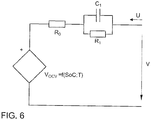
- a very simple mathematical model which relates measurable characteristics to non-measurable characteristics of an energy accumulator or battery would be a circuit constituted by a source of voltage V ocv , this voltage V ocv being function of the SoC and the T a , with a resistor R 0 in series, and another impedance in series constituted by two passive elements in parallel, C 1 and R 1 , with R 0 , R 1 and C 1 being functions of the SoC and the T a , and not constant parameters.
- This circuit would be supplied by a current U.
- This model is represented schematically in figure 6 .
- a method for estimating the state of charge of a battery which uses a model of the battery based on a multi-RC electric circuit designed to represent an open-circuit voltage and/or an impedance of a battery.
- a state observer can be used in relation with the estimation of parameters associated with the battery model.
- This methodology is based on the estimation of some of the parameters of the electric model of the battery.
- Impedance calculation is used based on FFT (fast Fourier transformations) at various frequencies and a Luenberger observer in order to correct the impedances.
- the function V ocv can be obtained from the calculation of the SoC, and a table of the LUT type (look-up table, or static tables) previously estimated, or by means of any other method.
- the initial conditions of the model are assumed to be known.
- a device is also known according to the prior art, as reflected in document US8099180 , for the determination of state-variables and/or parameters of a mathematical model of an energy accumulator, the electric properties of which are described on the basis of various variables of state and parameters.
- the mathematical model of the energy accumulator has correction equations by means of which the state-variables and/or the parameters are corrected and adjusted using the error between the voltage measurement of the energy accumulator and the voltage measurement of the model. This error is divided into different individual components equivalent to a proportional factor, a derivative factor, and another integral one, which are weighted using a weighting factor.
- An apparatus is also known in the prior art, as reflected in document EP0505333 , for the continuous estimation of the charge of electrochemical lead batteries, which apparatus includes data acquisition means for the measurement of the battery voltage, the current and the ambient temperature. It comprises a system for the conditioning and conversion for the signals of these data acquisition means, as well as a data processing system which is designed to provide information and any control signal with respect to all the operating parameters of the battery with reference to a predetermined dynamic model, in order to be able to simulate the performance of this battery.
- the battery charge is corrected by means of the error signals, according to the difference between the measured voltage and the estimated voltage obtained from a control or observer structure.
- the described method is based on the Kalman filter variant, wherein both parameters and states are estimated. If the states are known, the estimation of V ocv is direct, since the problem of the ideal/non-ideal cases is solved.
- the disadvantages of this method consist of the complexity involved, particularly at the time of implementation, and the compromise between complexity and precision. For methods based on Kalman filters which are not so complex, a series of parameters are necessary for a correct functioning (e.g. a matrix of covariance of the process). If these parameters are not precise, the method does not work well.
- the present invention consists of a method for the estimation of the function V ocv or open-circuit voltage of an energy accumulator in any type of situation, for possible subsequent use in the correction of the estimation of the state of charge of the accumulator.
- the energy accumulator is a battery or a battery cell of a motor vehicle.
- the situation can be both ideal and non-ideal.
- an ideal situation is that in which the motor vehicle is parked, and sufficient time has elapsed since its latest use for the intrinsic electrochemical reactions of the battery to reach a stationary state.
- many of the models known in the prior art are valid only in order to estimate the function V ocv in an ideal situation, i.e. in which the initial conditions are known.
- the present invention provides a method for estimation of the function V ocv both in ideal and non-ideal situations, i.e. by way of non-limiting example, a non-ideal situation is that in which the motor vehicle is running, or is parked but has only been so for a short time since its latest use, such that there is a current circulating through its battery circuit, and/or intrinsic electrochemical reactions are still running in the battery.
- a non-ideal situation therefore means that the initial conditions or initial state are not known. It should be noted that these situations are very common in the automotive industry.
- the present invention is resistant to parameter estimation errors in some of the descriptive parameters of the model of the energy accumulator.
- This method for the estimation of the function V ocv or open-circuit voltage 10 of an energy accumulator 2 is based on the structure of at least one Luenberger observer, which is the basic structure of a states observer of a linear system.
- the descriptive parameters of the energy accumulator model 2 are described by means of linearised functions around operating points which are normally dependent on the temperature measurement and the estimation of the state of charge of the energy accumulator.
- the function V ocv is observed using a Luenberger structure which is combined in an innovative manner. This combined structure makes it possible to observe the function V ocv without prior knowledge of the initial state of the battery or energy accumulator 2. It is carried out without needing any uncertain or approximate mathematical approximation.
- the simplicity of the structure is something to highlight, as it allows its technical viability with means of the present technology.
- a discontinuous line represents the estimation of V ocv by means of other methods based exclusively on a mathematical model of the energy accumulator, which do not include any control structure.
- this estimation is based on an electric accumulator model with 20% error in the parameters of the matrix B, and with lack of knowledge of the initial conditions.
- a continuous fine line represents the real value of V ocv .
- a continuous thick line represents the open-circuit voltage V ocv 11 estimated by means of the method according to the present invention, with the same conditions of 20% error in the parameters of the matrix B, and with lack of knowledge of the initial conditions.
- the lower shaded portion below each estimation of the function V ocv by means of the method according to the present invention represents the time during which the calculation process is executed.
- the objective of the method according to the present invention is to carry out an estimation of an open-circuit voltage 10 of an energy accumulator 2 with minimisation of the processing resources or consumption of resources by the control unit or data processing device, and overcoming of the possible errors of the descriptive parameters of the accumulator model.
- This estimation is used subsequently in order to correct the calculation of the state of charge of the energy accumulator, which can be carried out continuously by means of methods which are simple but prone to cumulative errors, already established, such as, and without excluding others, the Coulomb Counting method. Consequently, only intermittent corrections of the charge of the energy accumulator 2 are required.
- the present invention consists specifically of a method for calculation of an open-circuit voltage 10 of an energy accumulator 2, which comprises the following steps:
- the energy accumulator 2 has been defined in accordance with the model in figure 6 .
- this method is valid for both ideal and non-ideal situations, since the result of V ocv continues to be precise including when the energy accumulator 2, or battery, or battery cell, is not in an ideal situation (e.g. during a driving cycle, i.e. with current passing through it). It is also possible that, because of the ageing of the energy accumulator, the parameters B and D of the model may be affected by an incremental error over a period of time. Since this methodology is executed at moments when the electric current is null, the errors in these parameters do not affect the convergence result of V ocv . It should be noted that although reference is made generically to an energy accumulator 2, this is applicable to a battery or a cell of this battery.
- Figure 2 shows an example of demand for electricity by a plurality of electrical consumers of a motor vehicle 1 during a period of driving, and shows the value of the electric current supplied by the energy accumulator 2. This figure shows by means of circles with discontinue lines the moments in time when the current supplied is zero.
- figure 3 shows the moments in time when the open-circuit voltage 10 is constant. These are the moments in time which concur with the moments when the current measurement 3 is zero, as shown in figure 2 . This figure shows by means of circles with broken lines the moments in time when the open-circuit voltage 10 is constant.
- the step of determining the constant open-circuit voltage 10 V ocv of the constant energy accumulator 2 consists of obtaining a value of the electric current measurement u 3 which is close to zero.
- Value of the electric current measurement u 3 which is close to zero means when the current supplied by the energy accumulator 2 is very low compared with its capacity. Reference is then made to an electric current measurement u 3 which is close to zero or substantially null obtained during the predetermined period of time.
- the electric current value u 3 comprises a value which is close to zero is when an electric vehicle is stopped, or no energy is being supplied to the propulsion system of this vehicle.
- small consumers such as control units continue to function, since this consumption is very low in comparison with the capacity of the energy accumulator 2.
- the matrices A, B, C and D of the mathematical model of the energy accumulator 2 must be known.
- the step of determining the constant open-circuit voltage 10 V ocv of the energy accumulator 2 consists of obtaining a value of the electric current measurement u 3 which is equal to zero. It should then be noted that the zero value of the electric current measurement u 3 means a null value, i.e. when no energy accumulator 2 consumer exists.
- the step consists of observing, from amongst the electric current measurements 3 obtained, those which have a null value. When the value of the electric current measurement 3 is kept at null during the predetermined period of time, this means that the open-circuit voltage 10 of the energy accumulator 2 remains constant. It will be at this moment that the following steps described in the present method will be carried out.
- the electric current measurements 3 are null when the motor vehicle 1 is switched off.
- Another example is a motor vehicle 1 of a hybrid type, where the electric vehicle is being driven by the combustion engine, and therefore the energy accumulator 2 which supplies the electric drive motor is not supplying current.
- the electronics of the vehicle, or other electrical consumers, are supplied by another source of supply, such as another battery.
- the value of the electric current u 3 measured is equal to zero.
- the matrices A and C of the mathematic model of the energy accumulator 2 must be known.
- the matrices B and D can be partially unknown, with a certain error in their estimation.
- obtaining the value of the electric current measurement u 3 which is equal to zero consists of forcing an interruption of a first electrical supply by the energy accumulator 2 during the predetermined period of time.
- the electric current measurement u 3 will be equal to zero, and the method according to the present invention can be executed.
- forcing the interruption of the first electrical supply by the energy accumulator 2 consists of providing a second electrical supply by means of an additional device 8 during the predetermined period of time, such that an electric current supplied by the energy accumulator 2 and by the additional device 8 is continuous.
- the second electrical supply is enabled by the additional device 8, which can be another battery integrated in the motor vehicle 1, as shown in figure 1 .
- the current supplied is a value close to zero, such that the additional device 8 has a reduced or limited capacity.
- the method according to the present invention can gather the function V ocv even when the initial conditions are not known, i.e. with the battery or energy accumulator 2 in a state which is not relaxed at the moment when this method begins to be executed.
- a structure is used which is based on a Luenberger observer, in which the combination of the output error e V ⁇ , defined as (V- V ⁇ ), is equal to the function V ocv of the energy accumulator 2 once the stationary state has been reached (which is established after a certain period of time, of approximately a second).
- A, B, C and D are matrices, and are assumed to be known, or to have a tolerable error. These are the parameters which define the energy accumulator model 2, and characterise this model (in particular, each energy accumulator 2 has its own parameters A, B, C, D, with the exception of C which is a vector, and is constant for all the battery models).
- the errors at B and D are tolerable according to this invention, whereas A must be assumed to be known at all times.
- K is a variable 61 which defines a time of convergence of the calculation of the open-circuit voltage 10 of the energy accumulator 2 by means of the observer 41. This time can be reduced to less than a second, and during this period it is necessary to maintain the electric current measurement 3 to a null value. Otherwise, it is not necessary to carry out any calculation until the condition of the electric current measurement 3 is null for at least the convergence time indicated.
- e V ⁇ is a signal which is described as the difference between the voltage measured at the terminals of the energy accumulator 21 and the estimated voltage at the terminals of the energy accumulator 22 by the observer 41; t is the time; T is the temperature of the battery, on which the values of the parameters of the energy accumulator model depend.
- the model output estimation error is used in a conventional Luenberger structure as the system feedback, which in the present case is equivalent to V - V ⁇ , multiplied by a constant (which in this case would be equivalent to K).
- V OCV e V ⁇ CI A ⁇ KC ⁇ 1 K + 1 ⁇ 1
- this method can estimate the function V ocv with precision, without having, in the calculation process, any prior knowledge of the states-vector (x).
- the innovative way of application of this method makes it possible to estimate a non-measurable characteristic of the battery in any type of situation, including in a non-ideal situation (such as, in particular, during driving, without previously knowing the state of the battery (a condition caused by resetting, or a loss of memory of the computer unit of the motor vehicle 1), including when there are modelling errors in the descriptive parameters).
- the method according to the present invention has the advantage of ensuring precision in the results, irrespective of the state of the battery and/or its time of use, since it is dependent only on measurements of the battery itself, i.e. V, I and T a (voltage, current and temperature).
- this method makes it possible to observe the function V ocv without prior knowledge of the initial state of the energy accumulator 2, or the battery, or the battery cell, without needing any uncertain mathematical approximation and without being in a specific highly determining situation, such as when the vehicle has been stopped for a prolonged period of time (relaxed battery).
- variable which defines at least one state can be both scalar and a vector, and is not limited to one of the two. "At least one state" can be a single one, in the scalar case, or a plurality, in the case of the vector.
- the predetermined period of time is at least one second. Preferably, the predetermined period of time is substantially one second.
- the energy accumulator 2 is at least one cell of a battery.
- the energy accumulator 2 is a battery of a motor vehicle 1.
- the method according to the present invention can be used both for measurements from a low-voltage, small battery or energy accumulator 2, and for a high-voltage, or larger, battery or energy accumulator 2.
- the small one would be the typical battery of any motor vehicle 1 driven by fossil fuel.
- the large one would be the case of a battery to drive an electric or hybrid vehicle.
- the present invention also comprises a graphic representation device 5 which shows information relating to an open-circuit voltage 10 of an energy accumulator 2 V ocv , wherein the open-circuit voltage 10 of an energy accumulator 2 is calculated in accordance with the method of the present invention.
- the information displayed can be both the device's own information V ocv , or any other related information, such as a state of charge of the energy accumulator 2, or a graphic element representing it, which is estimated according to the V ocv calculated according to the above-described method.
- the graphic representation device 5 which shows information related to an open-voltage circuit 10 of an energy accumulator 2 is a screen of a motor vehicle 1, such that the user can easily access the information about the state of the energy accumulator 2 of his motor vehicle 1, from his driving position.
- An object of protection is also a data processing device which comprises means for executing the steps of the method for calculation of an open-circuit voltage 10 in accordance with the method of the present invention.
- an object of protection is also a computer program which comprises instructions in order, when the program is executed by a computer, to execute the method for calculation of an open-circuit voltage 10 in accordance with the method of the present invention.
Abstract
Description
- The subject of the present patent application is a method for the calculation of an open-circuit voltage of an energy accumulator according to
claim 1, which incorporates advantages of precision and speed of calculation, as well as an associated graphic representation device according to claim 12, which also incorporates significant advantages. The invention also relates to a data processing device according to claim 14, and to a computer program according to claim 15. - Nowadays there is a need in the automotive industry to determine some internal characteristics of a battery, for a better control and precision of the energy efficiency. However, some of these characteristics cannot be measured directly during the use of the battery, or even after a short period of time since its last use, and this prevents the results obtained on the basis of direct measurements from being precise and certain. Some of the internal characteristics of the battery cannot be measured during driving, since a current flow exists which involves internal chemical reactions which mask these characteristics. Thus, there is a need to provide a calculation method in order to determine at least one of the said characteristics, particularly the open-circuit voltage of the battery, even in those situations in which the energy accumulator is not in an ideal situation for the measurement.
- In some ideal conditions or situations, the relationship between the measurable characteristics of a battery and those which are not measurable is direct. This assists the fact that, in these situations, it is possible to succeed in determining internal characteristics of the battery using exclusively measurements which are available, or in other words, measurements which can be measured directly.
- However, when the conditions or situations are not ideal, the measurable characteristics cease to have a direct relationship with the non-measurable characteristics. Consequently, it is necessary to find a method which can relate the measurable and non-measurable characteristics in any situations or conditions, such that the results never cease being reliable.
- Measurable characteristics are defined as all the physical variables which can be determined by means of the general sensors or sensing means of the vehicle, which in this case, and without being exclusive of others, would be the: voltage, current or Ta (temperature), etc.
- Non-measurable characteristics are defined as all the functions which are not determined directly by means of the general sensors or sensing means of the vehicle, which in this case, and without being exclusive of others, would be the: SoC (State of Charge) of the battery, internal losses from the battery, etc.
- In addition, there are another type of characteristics which in certain ideal situations can be measured, and which however, when these situations change, are converted into non-measurable characteristics, such as, for example, and without excluding other characteristics, the open-circuit voltage function Vocv.
- A "Method capable of relating these types of characteristics" is defined as all the descriptive functions which can relate the behaviour of the measurable characteristics to the non-measurable characteristics with a certain degree of precision in the long term, for example a mathematical model.
- Thereby, the ideal situation for the measurement of characteristics of the energy accumulator or battery is considered to be the one in which there has not been an exchange of energy, in other words a current flow equal to zero, for a specific period of time. In particular, with reference to the motor vehicle field, this situation is associated with the one in which the vehicle has been parked for a period of time.
- Finally, a non-ideal situation is considered to be any case other than that previously described. In particular, with reference to the motor vehicle field, this situation is associated with that in which the vehicle is running, or when the battery is in use, or also in a state in which the vehicle has been parked but just a little time has elapsed since its latest use. In these situations, the prior state of use of the energy accumulator may not be known because of a stoppage of the processing units of the vehicle at the time of parking. If, when these processing units are restarted, the energy accumulator is not in a known state, in which this known state would be equivalent to an ideal situation, the calculation of, in this case and by way of non-limiting example, the voltage Vocv, cannot be carried out directly. Although the energy accumulator model is known, the calculation cannot be carried out directly because of lack of information about the state of this energy accumulator.
- A very simple mathematical model which relates measurable characteristics to non-measurable characteristics of an energy accumulator or battery would be a circuit constituted by a source of voltage Vocv, this voltage Vocv being function of the SoC and the Ta, with a resistor R0 in series, and another impedance in series constituted by two passive elements in parallel, C1 and R1, with R0, R1 and C1 being functions of the SoC and the Ta, and not constant parameters. This circuit would be supplied by a current U. This model is represented schematically in
figure 6 . - This model is extremely non-linear, since its descriptive functions, necessary to relate the measurable and non-measurable characteristics, have parameters which also depend on these characteristics. In addition, the voltage Vocv which appears in the output equation of the mathematical model impedes the direct implementation of methods which are known in the prior art.
- The calculation of the state of charge (SoC) of the battery is always related in some way to the voltage Vocv. In an ideal situation, this open-circuit voltage (Vocv) is directly related to the battery voltage (V). However, outside this ideal situation, estimation of the voltage Vocv is not easy, since it depends on each type of energy accumulator, the temperature, and also the level of use to which this energy accumulator has been subjected. The direct equation which calculates Vocv by means of the model previously described is: Vocv = V - η0 - η1, where V is the battery voltage, η0 is the overvoltage in the resistor R0, and η1 is the overvoltage in the passive element R1. Because of the mathematical description of this function, it is necessary to know the at least one state-variable of the battery model, which involves having to know the conditions of the battery itself at the moment which coincides with the start of calculation of the functions of the model (initial conditions).
- If these initial conditions described cannot be determined, then the calculation of the functions of the model does not make it possible, in a functional way, to succeed in determining the Vocv. These initial conditions are not known in the motor vehicle field when the situation is not ideal at the moment when calculation of the function is begun, i.e. when the vehicle is started before the battery has been able to reach a complete state of relaxation, in other words when it has been switched off and switched on in a given period of time (ranging from minutes to hours), or when the vehicle is being driven.
- At present there are not many techniques which estimate the value of Vocv in another way, and those which do use direct conversion tables using the SoC, which is risky if in turn good estimation of the state of charge is not available. Other methods use quite complex nonlinear techniques with mathematical approximations which are not always certain, or which cannot be implemented because of their complexity. For example, a quite common but complex technique consists of the use of Kalman filters and their non-linear variants (extended Kalman filters, etc.) in order to extract the function Vocv. This technique can involve complex challenges, and a lack of reliability in some applications.
- In addition, a method is known in the prior art, as reflected in document
US20150219726 , for estimating the state of charge of a battery which uses a model of the battery based on a multi-RC electric circuit designed to represent an open-circuit voltage and/or an impedance of a battery. A state observer can be used in relation with the estimation of parameters associated with the battery model. This methodology is based on the estimation of some of the parameters of the electric model of the battery. Impedance calculation is used based on FFT (fast Fourier transformations) at various frequencies and a Luenberger observer in order to correct the impedances. The function Vocv can be obtained from the calculation of the SoC, and a table of the LUT type (look-up table, or static tables) previously estimated, or by means of any other method. The initial conditions of the model are assumed to be known. - A device is also known according to the prior art, as reflected in document
US8099180 , for the determination of state-variables and/or parameters of a mathematical model of an energy accumulator, the electric properties of which are described on the basis of various variables of state and parameters. The mathematical model of the energy accumulator has correction equations by means of which the state-variables and/or the parameters are corrected and adjusted using the error between the voltage measurement of the energy accumulator and the voltage measurement of the model. This error is divided into different individual components equivalent to a proportional factor, a derivative factor, and another integral one, which are weighted using a weighting factor. - The use of the same components to adjust both the parameters of the model and its states does not make the viability of this technique apparent, and the design criteria for its implementation lack rigorousness, meaning that the applicability of this technique is unclear.
- An apparatus is also known in the prior art, as reflected in document
EP0505333 , for the continuous estimation of the charge of electrochemical lead batteries, which apparatus includes data acquisition means for the measurement of the battery voltage, the current and the ambient temperature. It comprises a system for the conditioning and conversion for the signals of these data acquisition means, as well as a data processing system which is designed to provide information and any control signal with respect to all the operating parameters of the battery with reference to a predetermined dynamic model, in order to be able to simulate the performance of this battery. The battery charge is corrected by means of the error signals, according to the difference between the measured voltage and the estimated voltage obtained from a control or observer structure. - Thus, this method focuses on estimating the remaining charge in the battery, and not on carrying out a prior estimation of Vocv. In addition, it is important to indicate the following points:
- In cases in which the initial conditions of the model are not known, the system is slow and inaccurate (even more so in batteries where the dynamics are generally slow). The reason is that the control structure, which permits correction of the error, is implemented once the voltage value Vocv has been obtained, which affects the obtaining of the estimated charge value, thus requiring many iterations in order to obtain a precise value.
- According to the type of battery analysed, the estimation method according to the invention can take many minutes to obtain an estimated charge value which converges towards the real charge value.
- In order for the estimated charge value to be precise, the method according to the invention must be processed and iterated continually. Once the estimated charge value is substantially equal to the real charge of the battery, the method according to the present invention requires continuous processing. Otherwise, the estimated charge would become distanced from the real value, once again requiring a long time until the estimated charge value converges towards that of the real charge. As previously stated, the motive will be to start once again with initial conditions which are not known, and the application of control correction of the error outside the load estimation model.
- There is also known in the prior art, as reflected in document
US7109685 , a method for estimation of a state of charge (SoC) and a state of health (SoH) of an electrochemical cell (CE), which includes modelling of the electrochemical cell in a linear equation, measurement of a terminal current of the electrochemical cell, measurement of a voltage at the terminals of the electrochemical cell, and measurement of a temperature of the electrochemical cell. The linear equation is processed by means of a state estimator and parameters using the aforementioned measurements. - The described method is based on the Kalman filter variant, wherein both parameters and states are estimated. If the states are known, the estimation of Vocv is direct, since the problem of the ideal/non-ideal cases is solved. The disadvantages of this method consist of the complexity involved, particularly at the time of implementation, and the compromise between complexity and precision. For methods based on Kalman filters which are not so complex, a series of parameters are necessary for a correct functioning (e.g. a matrix of covariance of the process). If these parameters are not precise, the method does not work well.
- Therefore, it can be seen that there is still a need to have a method for calculation of an open- circuit voltage of an energy accumulator and associated graphic representation device such that a precise and rapid result is obtained in the estimation of the voltage Vocv, even when there are errors in the estimations of the model because the initial states are not known. In addition, it is desired to reduce the complexity of the known models and reduce the processing resources required by the control unit. This means that this estimation can be carried out for example during driving, without this altering either the precision or the reliability of the results.
- The present invention consists of a method for the estimation of the function Vocv or open-circuit voltage of an energy accumulator in any type of situation, for possible subsequent use in the correction of the estimation of the state of charge of the accumulator. It is understood, more specifically, but not restrictively, that the energy accumulator is a battery or a battery cell of a motor vehicle. It is also understood that the situation can be both ideal and non-ideal. By way of non-limiting example, an ideal situation is that in which the motor vehicle is parked, and sufficient time has elapsed since its latest use for the intrinsic electrochemical reactions of the battery to reach a stationary state. It should be noted that many of the models known in the prior art are valid only in order to estimate the function Vocv in an ideal situation, i.e. in which the initial conditions are known.
- Alternatively, the present invention provides a method for estimation of the function Vocv both in ideal and non-ideal situations, i.e. by way of non-limiting example, a non-ideal situation is that in which the motor vehicle is running, or is parked but has only been so for a short time since its latest use, such that there is a current circulating through its battery circuit, and/or intrinsic electrochemical reactions are still running in the battery. A non-ideal situation therefore means that the initial conditions or initial state are not known. It should be noted that these situations are very common in the automotive industry. In addition, the present invention is resistant to parameter estimation errors in some of the descriptive parameters of the model of the energy accumulator.
- The invention will be described with reference to the appended drawings which show by way of non-limiting example a method for calculation of an open-circuit voltage of an energy accumulator, and associated graphic representation device, constituted according to the invention. Other characteristics and advantages of this method for the calculation of an open-circuit voltage of an energy accumulator, and associated graphic representation device which are the subject of the present invention, will become apparent from the description of a preferred, but not exclusive embodiment, which is illustrated by way of non-limiting example in the accompanying drawings, in which:
-
-
Figure 1 is a lateral view of a vehicle which comprises two energy accumulators according to the present invention. -
Figure 2 is a graphic representation of a possible electric current u, according to the present invention. -
Figure 3 is a graphic representation of a possible open-circuit voltage of the energy accumulator Vocv , according to the present invention. -
Figure 4A is a representation of the main equations which follows the method according to the present invention. -
Figure 4B is a detailed graphic representation of one of the periods during which the measurement of the function Vocv is estimated according to the method of the present invention. -
Figure 5 is a graphic representation which compares the estimation of the function Vocv by means of a methodology known in the prior art and the method according to the present invention. -
Figure 6 is a graphic representation of a generic first-order model of an energy accumulator based on an electrical-description circuit.. - In the light of the aforementioned figures, and in accordance with the numbering adopted, an example can be seen of a preferred embodiment of the invention, comprising the parts and elements which are indicated and described in detail hereinafter.
- This method for the estimation of the function Vocv or open-
circuit voltage 10 of anenergy accumulator 2 is based on the structure of at least one Luenberger observer, which is the basic structure of a states observer of a linear system. In order to overcome the non-linearities of the system, the descriptive parameters of theenergy accumulator model 2 are described by means of linearised functions around operating points which are normally dependent on the temperature measurement and the estimation of the state of charge of the energy accumulator. The function Vocv is observed using a Luenberger structure which is combined in an innovative manner. This combined structure makes it possible to observe the function Vocv without prior knowledge of the initial state of the battery orenergy accumulator 2. It is carried out without needing any uncertain or approximate mathematical approximation. The simplicity of the structure is something to highlight, as it allows its technical viability with means of the present technology. - Thus, and by way of example, the graphic representation in
figure 5 is presented, showing a comparison of the open-circuit voltage 10 according to methods known in the prior art and the method according to the present invention. In this matter, a discontinuous line represents the estimation of Vocv by means of other methods based exclusively on a mathematical model of the energy accumulator, which do not include any control structure. In this example, this estimation is based on an electric accumulator model with 20% error in the parameters of the matrix B, and with lack of knowledge of the initial conditions. In addition, a continuous fine line represents the real value of Vocv. Finally, a continuous thick line represents the open-circuit voltage V ocv 11 estimated by means of the method according to the present invention, with the same conditions of 20% error in the parameters of the matrix B, and with lack of knowledge of the initial conditions. The lower shaded portion below each estimation of the function Vocv by means of the method according to the present invention represents the time during which the calculation process is executed. - Therefore, and as shown in
figure 5 , the objective of the method according to the present invention is to carry out an estimation of an open-circuit voltage 10 of anenergy accumulator 2 with minimisation of the processing resources or consumption of resources by the control unit or data processing device, and overcoming of the possible errors of the descriptive parameters of the accumulator model. This estimation is used subsequently in order to correct the calculation of the state of charge of the energy accumulator, which can be carried out continuously by means of methods which are simple but prone to cumulative errors, already established, such as, and without excluding others, the Coulomb Counting method. Consequently, only intermittent corrections of the charge of theenergy accumulator 2 are required. Therefore, periodic corrections of the state of charge are carried out by means of the estimation results obtained by means of the method according to the present invention and a characteristic table which relates the open-circuit voltage (Vocv) to the state of charge. Therefore, a method is obtained which does not require continuous processing in order to obtain an estimated charge value which converges towards the real charge value, and carries out only intermittent corrections which succeed in solving the problem of the unknown initial conditions (non-ideal situations), and that of the imprecise parameters of the model. The following points can be distinguished: - A period of time of a few milliseconds is required by the present method to obtain a charge value which converges toward the real charge value. By this means, and advantageously, at intermittent moments and very short intervals of time, it will be possible to correct the charge value of the
energy accumulator 2. - The method according to the present invention is executed when the function Vocv or open-
circuit voltage 10 is constant, by way of example when themotor vehicle 1 is stopped or the energy accumulator is not used during driving (by way of example situations in which acceleration or braking do not take place). It will be at this time that the method is executed for the purpose of correcting the charge of theenergy accumulator 2. - It is also observed that there is minimisation of the consumption of resources required in order to execute the method according to the present invention, by limiting it only to intermittent moments which make it possible to obtain a estimated charge value that converges towards the real charge value, consequently correcting at this time the charge value of the
energy accumulator 2 obtained by means of other simple methods which require corrections. - Thus, the present invention consists specifically of a method for calculation of an open-
circuit voltage 10 of anenergy accumulator 2, which comprises the following steps: - i) establishing a definition for the
energy accumulator 2 according to a system of equations and a plurality of descriptive parameters in accordance with the following equation:

energy accumulator 2, ẋ is the temporal derivative of the variable which defines at least one state of the energy accumulator 2 x, A, B, C and D are a plurality of matrices which constitute the performance of theenergy accumulator 2, u is a measurement of electric current 3 which circulates through theenergy accumulator 2, V is a voltage measured at the terminals of the energy accumulator 21, and Vocv is an open-circuit voltage 10 of theenergy accumulator 2; - ii) obtaining the measurement of the electric
current u 3 which circulates through theenergy accumulator 2; - iii) determining on the basis of the electric
current measurement u 3 obtained that the open-circuit voltage 10 Vocv of theenergy accumulator 2 is constant for a predetermined period of time; - iv) obtaining the voltage measured at the terminals of the energy accumulator 21;
- v) calculating an estimated voltage at the terminals of the energy accumulator V̂ 22 by means of an observer 41, wherein the observer 41 is defined by means of a specific control structure;
- vi) calculating the open-
circuit voltage V ocv 10 of theenergy accumulator 2 by means of the formula:
energy accumulator V ocv 10 by means of the observer 41. - As previously stated, the
energy accumulator 2 has been defined in accordance with the model infigure 6 . - Advantageously, this method is valid for both ideal and non-ideal situations, since the result of Vocv continues to be precise including when the
energy accumulator 2, or battery, or battery cell, is not in an ideal situation (e.g. during a driving cycle, i.e. with current passing through it). It is also possible that, because of the ageing of the energy accumulator, the parameters B and D of the model may be affected by an incremental error over a period of time. Since this methodology is executed at moments when the electric current is null, the errors in these parameters do not affect the convergence result of Vocv. It should be noted that although reference is made generically to anenergy accumulator 2, this is applicable to a battery or a cell of this battery. -
Figure 2 shows an example of demand for electricity by a plurality of electrical consumers of amotor vehicle 1 during a period of driving, and shows the value of the electric current supplied by theenergy accumulator 2. This figure shows by means of circles with discontinue lines the moments in time when the current supplied is zero. - In addition,
figure 3 shows the moments in time when the open-circuit voltage 10 is constant. These are the moments in time which concur with the moments when thecurrent measurement 3 is zero, as shown infigure 2 . This figure shows by means of circles with broken lines the moments in time when the open-circuit voltage 10 is constant. - According to a first application of the present invention, the step of determining the constant open-circuit voltage 10 Vocv of the
constant energy accumulator 2 consists of obtaining a value of the electriccurrent measurement u 3 which is close to zero. Value of the electriccurrent measurement u 3 which is close to zero means when the current supplied by theenergy accumulator 2 is very low compared with its capacity. Reference is then made to an electriccurrent measurement u 3 which is close to zero or substantially null obtained during the predetermined period of time. - An example where the electric
current value u 3 comprises a value which is close to zero is when an electric vehicle is stopped, or no energy is being supplied to the propulsion system of this vehicle. Thus, small consumers such as control units continue to function, since this consumption is very low in comparison with the capacity of theenergy accumulator 2. In an example such as the one previously presented, the matrices A, B, C and D of the mathematical model of theenergy accumulator 2 must be known. - According to a second application of the present invention, the step of determining the constant open-circuit voltage 10 Vocv of the
energy accumulator 2 consists of obtaining a value of the electriccurrent measurement u 3 which is equal to zero. It should then be noted that the zero value of the electriccurrent measurement u 3 means a null value, i.e. when noenergy accumulator 2 consumer exists. The step consists of observing, from amongst the electriccurrent measurements 3 obtained, those which have a null value. When the value of the electriccurrent measurement 3 is kept at null during the predetermined period of time, this means that the open-circuit voltage 10 of theenergy accumulator 2 remains constant. It will be at this moment that the following steps described in the present method will be carried out. By way of example, the electriccurrent measurements 3 are null when themotor vehicle 1 is switched off. - Another example is a
motor vehicle 1 of a hybrid type, where the electric vehicle is being driven by the combustion engine, and therefore theenergy accumulator 2 which supplies the electric drive motor is not supplying current. The electronics of the vehicle, or other electrical consumers, are supplied by another source of supply, such as another battery. In this case, the value of the electriccurrent u 3 measured is equal to zero. In an example such as the one presented previously, the matrices A and C of the mathematic model of theenergy accumulator 2 must be known. On the other hand, the matrices B and D can be partially unknown, with a certain error in their estimation. - According to another aspect of the present invention, obtaining the value of the electric
current measurement u 3 which is equal to zero consists of forcing an interruption of a first electrical supply by theenergy accumulator 2 during the predetermined period of time. Thus, by forcing the interruption of the first electrical supply, the electriccurrent measurement u 3 will be equal to zero, and the method according to the present invention can be executed. - More particularly, forcing the interruption of the first electrical supply by the
energy accumulator 2 consists of providing a second electrical supply by means of an additional device 8 during the predetermined period of time, such that an electric current supplied by theenergy accumulator 2 and by the additional device 8 is continuous. This then means that, for the purpose of countering the interruption of the electrical supply of theenergy accumulator 2, the second electrical supply is enabled by the additional device 8, which can be another battery integrated in themotor vehicle 1, as shown infigure 1 . It should be remembered that the current supplied is a value close to zero, such that the additional device 8 has a reduced or limited capacity. - By these means, the method according to the present invention can gather the function Vocv even when the initial conditions are not known, i.e. with the battery or
energy accumulator 2 in a state which is not relaxed at the moment when this method begins to be executed. In the case of the present invention, a structure is used which is based on a Luenberger observer, in which the combination of the output error e V̂ , defined as (V-V̂), is equal to the function Vocv of theenergy accumulator 2 once the stationary state has been reached (which is established after a certain period of time, of approximately a second). - The terms used are defined as follows:
- x is a variable which defines at least one state of the
energy accumulator 2; - ẋ the temporal derivative of the variable which defines at least one state of the
energy accumulator 2; - V is a voltage measured at the terminals of the energy accumulator 21;
- V̂ is an estimated voltage at the terminals of the energy accumulator 22;
- u the input of the equations system (on the battery model), and corresponds to measurement of the electric current 3 which is circulating through the
energy accumulator 2; - Vocv is the open-
circuit voltage 10 of the energy accumulator, 2, or more specifically of the battery, estimated during driving. - A, B, C and D are matrices, and are assumed to be known, or to have a tolerable error. These are the parameters which define the
energy accumulator model 2, and characterise this model (in particular, eachenergy accumulator 2 has its own parameters A, B, C, D, with the exception of C which is a vector, and is constant for all the battery models). The errors at B and D are tolerable according to this invention, whereas A must be assumed to be known at all times. - K is a variable 61 which defines a time of convergence of the calculation of the open-
circuit voltage 10 of theenergy accumulator 2 by means of the observer 41. This time can be reduced to less than a second, and during this period it is necessary to maintain the electriccurrent measurement 3 to a null value. Otherwise, it is not necessary to carry out any calculation until the condition of the electriccurrent measurement 3 is null for at least the convergence time indicated. - e V̂ is a signal which is described as the difference between the voltage measured at the terminals of the energy accumulator 21 and the estimated voltage at the terminals of the energy accumulator 22 by the observer 41;
t is the time;
T is the temperature of the battery, on which the values of the parameters of the energy accumulator model depend. - It is important to mention that the conventional structure of a Luenberger observer 41 is known, and it is used for estimating states in very basic systems, where no unknown functions appear at the output of the model (in the case of the present invention Vocv would be an unknown function which affects the output of the model). This observer 41 and the subsequent control of its error make it possible to obtain, as a result, the function which affects the output of the present model.
- Thus, and as observed in
figure 4A , the model output estimation error is used in a conventional Luenberger structure as the system feedback, which in the present case is equivalent to V - V̂, multiplied by a constant (which in this case would be equivalent to K). - The feedback of the observer 41 structure follows the conventional architecture. Expressed in algebraic form, the observer structure proposed for the
energy accumulator 2 is:

- The conventional structure of a Luenberger observer is traditionally used for calculation of the states-vector (x) of a system, or mathematical model, based on the following formulation:


energy accumulator 2, or more particularly themotor vehicle 1 battery. - However, the formulation of the mathematical model of the battery, represented in
figure 6 , does not have a form which corresponds to the system previously described (the conventional one on which the Luenberger system is based). For this reason, the calculation of the estimated states-vector using the method described here (x̂) does not match with the states-vector from the plant (x). However, the proposed further combination of the estimation error of the voltage at the terminals of the accumulator ( e V̂ = V - V̂) makes it possible to determine the aforementioned function Vocv. Once this function Vocv is known, it is simple to use a Look Up Table in order to obtain the state of charge at the moment when the correction is carried out. - The manner of combining the error e V̂ with the other parameters of the model is as follows:

- Therefore, this method can estimate the function Vocv with precision, without having, in the calculation process, any prior knowledge of the states-vector (x). To summarise, the innovative way of application of this method makes it possible to estimate a non-measurable characteristic of the battery in any type of situation, including in a non-ideal situation (such as, in particular, during driving, without previously knowing the state of the battery (a condition caused by resetting, or a loss of memory of the computer unit of the motor vehicle 1), including when there are modelling errors in the descriptive parameters).
- In addition, it can be observed that the method according to the present invention has the advantage of ensuring precision in the results, irrespective of the state of the battery and/or its time of use, since it is dependent only on measurements of the battery itself, i.e. V, I and Ta (voltage, current and temperature).
- Furthermore, this method makes it possible to observe the function Vocv without prior knowledge of the initial state of the
energy accumulator 2, or the battery, or the battery cell, without needing any uncertain mathematical approximation and without being in a specific highly determining situation, such as when the vehicle has been stopped for a prolonged period of time (relaxed battery). - More specifically, the estimated voltage at the terminals of the energy accumulator 22 by the control structure of the observer 41 is obtained according to the formula:

energy accumulator 2 estimated by means of the observer 41. - It should be noted that the variable which defines at least one state can be both scalar and a vector, and is not limited to one of the two. "At least one state" can be a single one, in the scalar case, or a plurality, in the case of the vector.
- According to another aspect of the method of the invention, the variable which defines at least one estimated state of the energy accumulator x̂ is calculated by solving a first differential equation of the type:
 is the temporal derivative of the variable which defines at least one estimated state of the
energy accumulator 2 x̂. - This method provides advantages such as:
- greater speed in obtaining the result compared with the present methods.
- greater precision in further calculations of other parameters of the battery or energy accumulator 2 (SoC, current limits, etc.). When basic methods are used for estimating the state of charge, which require of periodic corrections because of cumulative errors, the present invention has the requirements in order to work well with these estimations in the case of the automotive industry.
- robustness, simplicity and reliability, in the sense that it does not bring any hurdle defining complicated parameters in order for it towork, or in relation to the input data used, since it is valid for any kindof situation, whether ideal (in particular when the
vehicle 1 has been parked for a long period of time, meaning that there is no current applied in its battery circuit), or non-ideal (in particular with themotor vehicle 1 running, and therefore having current flowing through its battery circuit, being only necessary a condition of null current for a short period of time). It is also observed that even when there are errors in the parameters of the model, the error of estimation of Vocv is substantially null. - According to an aspect of the invention, the predetermined period of time is at least one second. Preferably, the predetermined period of time is substantially one second.
- It should be noted that the
energy accumulator 2 is at least one cell of a battery. - According to a preferred embodiment of the invention, the
energy accumulator 2 is a battery of amotor vehicle 1. - It is indicated that, as observed in
figure 1 , the method according to the present invention can be used both for measurements from a low-voltage, small battery orenergy accumulator 2, and for a high-voltage, or larger, battery orenergy accumulator 2. The small one would be the typical battery of anymotor vehicle 1 driven by fossil fuel. The large one would be the case of a battery to drive an electric or hybrid vehicle. - In addition, as can be seen from
figures 1 and4 , the present invention also comprises agraphic representation device 5 which shows information relating to an open-circuit voltage 10 of an energy accumulator 2 Vocv , wherein the open-circuit voltage 10 of anenergy accumulator 2 is calculated in accordance with the method of the present invention. - By these means, the information displayed can be both the device's own information Vocv , or any other related information, such as a state of charge of the
energy accumulator 2, or a graphic element representing it, which is estimated according to the Vocv calculated according to the above-described method. - Advantageously, the
graphic representation device 5 which shows information related to an open-voltage circuit 10 of anenergy accumulator 2 is a screen of amotor vehicle 1, such that the user can easily access the information about the state of theenergy accumulator 2 of hismotor vehicle 1, from his driving position. - An object of protection is also a data processing device which comprises means for executing the steps of the method for calculation of an open-
circuit voltage 10 in accordance with the method of the present invention. - In addition, an object of protection is also a computer program which comprises instructions in order, when the program is executed by a computer, to execute the method for calculation of an open-
circuit voltage 10 in accordance with the method of the present invention. - It should be noted that the method for the calculation of an open-circuit voltage of an energy accumulator is easy to implement, with low consumption of RAM/ROM memory, and brings the possibility of rapid calculation without advanced hardware.
- The details, forms, dimensions and other accessory elements, as well as the components used in the implementation of the method for calculation of an open-circuit voltage of an energy accumulator and associated graphic representation device can conveniently be substituted by others which are technically equivalent, and do not depart from the essential nature of the invention or from the context defined by the claims which are included after the following list.
-
- 1
- motor vehicle
- 10
- open-circuit voltage Vocv
- 11
- estimated open-circuit voltage Vocv
- 2
- energy accumulator
- 20
- signal e V̂
- 21
- voltage measured at the terminals of the energy accumulator V
- 22
- estimated voltage at the terminals of the energy accumulator V̂
- 3
- electric current measurement u
- 41
- observer
- 5
- graphic representation device
- 61
- variable K
- 8
- additional device
Claims (15)
- Method for the calculation of an open-circuit voltage (10) of an energy accumulator (2), which comprises the following steps:i) establishing a definition for the energy accumulator (2) according to a system of equations and a plurality of descriptive parameters in accordance with the following equation:

 ii) obtaining the measurement of the electric current u (3) which circulates through the energy accumulator (2);iii) determining on the basis of the electric current measurement u (3) obtained that the open-circuit voltage (10) Vocv of the energy accumulator (2) is constant for a predetermined period of time;iv) obtaining the voltage measured at the terminals of the energy accumulator V (21);v) calculating an estimated voltage at the terminals of the energy accumulator V̂ (22) by means of an observer (41), wherein the observer (41) is defined by means of a specific control structure;vi) calculating the open-circuit voltage Vocv (10) of the energy accumulator (2) by means of the formula:
- Method for the calculation of an open-circuit voltage (10) of an energy accumulator (2) according to Claim 1, characterized in that the step of determining the constant open-circuit voltage (10) Vocv of the energy accumulator (2) consists of obtaining a value of the electric current measurement u (3) which is close to zero.
- Method for the calculation of an open-circuit voltage (10) of an energy accumulator (2) according to Claim 1, characterized in that the step of determining the constant open-circuit voltage (10) Vocv of the energy accumulator (2) consists of obtaining a value of the electric current measurement u (3) which is equal to zero.
- Method for the calculation of an open-circuit voltage (10) of an energy accumulator (2) according to Claim 3, characterized in that obtaining the value of the electric current measurement u (3) which is equal to zero consists of forcing an interruption of a first electrical supply by the energy accumulator (2) during the predetermined period of time.
- Method for the calculation of an open-circuit voltage (10) of an energy accumulator (2) according to Claim 4, characterized in that forcing the interruption of the first electrical supply by the energy accumulator (2) consists of providing a second electrical supply by means of an additional device (8) during the predetermined period of time, such that an electric current supplied by the energy accumulator (2) and by the additional device (8) is continuous.
- Method for the calculation of an open-circuit voltage (10) of an energy accumulator (2) according to Claim 1, characterized in that the estimated voltage at the terminals of the energy accumulator V̂ (22) by the control structure of the observer (41) is obtained according to the formula:

- Method for the calculation of an open-circuit voltage (10) of an energy accumulator (2) according to Claim 6, characterized in that the variable which defines at least one estimated state of the energy accumulator (2) x̂ is calculated by solving a first differential equation of the type:
 is the temporal derivative of the variable which defines at least one estimated state of the energy accumulator (2) x̂.
- Method for the calculation of an open-circuit voltage (10) of an energy accumulator (2) according to Claim 1, characterized in that the predetermined period of time is at least one second.
- Method for the calculation of an open-circuit voltage (10) of an energy accumulator (2) according to Claim 1, characterized in that the predetermined period of time is substantially one second.
- Method for the calculation of an open-circuit voltage (10) of an energy accumulator (2) according to Claim 1, characterized in that the energy accumulator (2) is at least one cell of a battery.
- Method for the calculation of an open-circuit voltage (10) of an energy accumulator (2) according to Claim 1, characterized in that the energy accumulator (2) is a battery of a motor vehicle (1).
- Graphic representation device (5) which shows information relating to an open-circuit voltage (10) of an energy accumulator (2) Vocv , characterized in that the open-circuit voltage (10) of an energy accumulator (2) Vocv is calculated in accordance with the method of Claims 1-11.
- Graphic representation device (5) which shows information relating to an open-circuit voltage (10) of an energy accumulator (2) Vocv , characterized in that the graphic representation device (5) is a screen of a motor vehicle (1).
- Data processing device which comprises means for executing the steps of the method for calculation of an open-circuit voltage (10) in accordance with Claims 1-11.
- Computer program which comprises instructions in order, when the program is executed by a computer, to execute the method for calculation of an open-circuit voltage (10) in accordance with Claims 1-11.
Priority Applications (1)
| Application Number | Priority Date | Filing Date | Title |
|---|---|---|---|
| EP16382671.2A EP3343389B1 (en) | 2016-12-29 | 2016-12-29 | Method for the calculation of an open-circuit voltage of an energy accumulator, and associated graphic representation device |
Applications Claiming Priority (1)
| Application Number | Priority Date | Filing Date | Title |
|---|---|---|---|
| EP16382671.2A EP3343389B1 (en) | 2016-12-29 | 2016-12-29 | Method for the calculation of an open-circuit voltage of an energy accumulator, and associated graphic representation device |
Publications (2)
| Publication Number | Publication Date |
|---|---|
| EP3343389A1 true EP3343389A1 (en) | 2018-07-04 |
| EP3343389B1 EP3343389B1 (en) | 2022-12-21 |
Family
ID=57850869
Family Applications (1)
| Application Number | Title | Priority Date | Filing Date |
|---|---|---|---|
| EP16382671.2A Active EP3343389B1 (en) | 2016-12-29 | 2016-12-29 | Method for the calculation of an open-circuit voltage of an energy accumulator, and associated graphic representation device |
Country Status (1)
| Country | Link |
|---|---|
| EP (1) | EP3343389B1 (en) |
Cited By (2)
| Publication number | Priority date | Publication date | Assignee | Title |
|---|---|---|---|---|
| CN109148981A (en) * | 2018-07-13 | 2019-01-04 | 东软集团股份有限公司 | Determine method, apparatus, storage medium and the electronic equipment of battery open circuit voltage |
| CN116930819A (en) * | 2023-09-18 | 2023-10-24 | 云南电网有限责任公司 | Current terminal strip temperature on-line monitoring method and system based on thermal imaging |
Citations (5)
| Publication number | Priority date | Publication date | Assignee | Title |
|---|---|---|---|---|
| EP0505333A2 (en) | 1991-03-18 | 1992-09-23 | Ente per le nuove tecnologie, l'energia e l'ambiente ( ENEA) | Estimating the charge of batteries |
| US6534954B1 (en) * | 2002-01-10 | 2003-03-18 | Compact Power Inc. | Method and apparatus for a battery state of charge estimator |
| US7109685B2 (en) | 2003-09-17 | 2006-09-19 | General Motors Corporation | Method for estimating states and parameters of an electrochemical cell |
| US8099180B2 (en) | 2004-07-23 | 2012-01-17 | Robert Bosch Gmbh | State and parameter estimator having integral and differential components for electrical energy accumulators |
| US20150219726A1 (en) | 2014-02-03 | 2015-08-06 | GM Global Technology Operations LLC | Systems and methods for battery state estimation |
-
2016
- 2016-12-29 EP EP16382671.2A patent/EP3343389B1/en active Active
Patent Citations (5)
| Publication number | Priority date | Publication date | Assignee | Title |
|---|---|---|---|---|
| EP0505333A2 (en) | 1991-03-18 | 1992-09-23 | Ente per le nuove tecnologie, l'energia e l'ambiente ( ENEA) | Estimating the charge of batteries |
| US6534954B1 (en) * | 2002-01-10 | 2003-03-18 | Compact Power Inc. | Method and apparatus for a battery state of charge estimator |
| US7109685B2 (en) | 2003-09-17 | 2006-09-19 | General Motors Corporation | Method for estimating states and parameters of an electrochemical cell |
| US8099180B2 (en) | 2004-07-23 | 2012-01-17 | Robert Bosch Gmbh | State and parameter estimator having integral and differential components for electrical energy accumulators |
| US20150219726A1 (en) | 2014-02-03 | 2015-08-06 | GM Global Technology Operations LLC | Systems and methods for battery state estimation |
Non-Patent Citations (5)
| Title |
|---|
| LIEVRE AURELIEN ET AL: "Luenberger observer for SoC determination of lithium-ion cells in mild hybrid vehicles, compared to a Kalman filter", 2015 TENTH INTERNATIONAL CONFERENCE ON ECOLOGICAL VEHICLES AND RENEWABLE ENERGIES (EVER), IEEE, 31 March 2015 (2015-03-31), pages 1 - 7, XP032780626, DOI: 10.1109/EVER.2015.7112986 * |
| LINFENG ZHENG ET AL: "Embedded implementation of SOC estimation based on the Luenberger observer technique", 2014 IEEE CONFERENCE AND EXPO TRANSPORTATION ELECTRIFICATION ASIA-PACIFIC (ITEC ASIA-PACIFIC), IEEE, 31 August 2014 (2014-08-31), pages 1 - 4, XP032671532, DOI: 10.1109/ITEC-AP.2014.6941037 * |
| LIU ZHENTONG ET AL: "Structural analysis based sensors fault detection and isolation of cylindrical lithium-ion batteries in automotive applications", CONTROL ENGINEERING PRACTICE, PERGAMON PRESS, OXFORD, GB, vol. 52, 19 April 2016 (2016-04-19), pages 46 - 58, XP029545446, ISSN: 0967-0661, DOI: 10.1016/J.CONENGPRAC.2016.03.015 * |
| TAESIC KIM ET AL: "Real-time state of charge and electrical impedance estimation for lithium-ion batteries based on a hybrid battery model", APPLIED POWER ELECTRONICS CONFERENCE AND EXPOSITION (APEC), 2013 TWENTY-EIGHTH ANNUAL IEEE, IEEE, 17 March 2013 (2013-03-17), pages 563 - 568, XP032410393, ISBN: 978-1-4673-4354-1, DOI: 10.1109/APEC.2013.6520266 * |
| YANG FANGFANG ET AL: "A comparative study of three model-based algorithms for estimating state-of-charge of lithium-ion batteries under a new combined dynamic loading profile", APPLIED ENERGY, ELSEVIER SCIENCE PUBLISHERS, GB, vol. 164, 22 December 2015 (2015-12-22), pages 387 - 399, XP029386944, ISSN: 0306-2619, DOI: 10.1016/J.APENERGY.2015.11.072 * |
Cited By (4)
| Publication number | Priority date | Publication date | Assignee | Title |
|---|---|---|---|---|
| CN109148981A (en) * | 2018-07-13 | 2019-01-04 | 东软集团股份有限公司 | Determine method, apparatus, storage medium and the electronic equipment of battery open circuit voltage |
| CN109148981B (en) * | 2018-07-13 | 2020-05-08 | 东软集团股份有限公司 | Method and device for determining open-circuit voltage of battery, storage medium and electronic equipment |
| CN116930819A (en) * | 2023-09-18 | 2023-10-24 | 云南电网有限责任公司 | Current terminal strip temperature on-line monitoring method and system based on thermal imaging |
| CN116930819B (en) * | 2023-09-18 | 2023-12-08 | 云南电网有限责任公司 | Current terminal strip temperature on-line monitoring method and system based on thermal imaging |
Also Published As
| Publication number | Publication date |
|---|---|
| EP3343389B1 (en) | 2022-12-21 |
Similar Documents
| Publication | Publication Date | Title |
|---|---|---|
| Wassiliadis et al. | Revisiting the dual extended Kalman filter for battery state-of-charge and state-of-health estimation: A use-case life cycle analysis | |
| EP3593155B1 (en) | A battery cell state of charge estimation method and a battery state monitoring system | |
| CN113466723B (en) | Method and device for determining state of charge of battery and battery management system | |
| US10807494B2 (en) | Battery management system, battery system and hybrid vehicle control system | |
| Remmlinger et al. | On-board state-of-health monitoring of lithium-ion batteries using linear parameter-varying models | |
| EP3309567A1 (en) | Method and device for estimating remaining available energy of a power battery | |
| JP6404832B2 (en) | Method of determining control technical observer for SoC | |
| US9205755B2 (en) | Receding horizon regression analysis for battery impedance parameter estimation | |
| DE102004036302B4 (en) | Simple optimum value estimator for the state of charge of a lead power source | |
| WO2016129248A1 (en) | Secondary battery state-of-charge estimating device and secondary battery state-of-charge estimating method | |
| Fleischer et al. | On-line self-learning time forward voltage prognosis for lithium-ion batteries using adaptive neuro-fuzzy inference system | |
| EP3780248B1 (en) | Degradation state determination device and degradation state determination method | |
| DE102015202540A1 (en) | BATTERY CAPACITY ESTIMATION USING A CONCEPT OF FLYING CHARGING INITIALIZATION | |
| US20100312744A1 (en) | System for battery prognostics | |
| DE102015103561A1 (en) | FREQUENCY BASED ESTIMATION OF BATTERY MODEL PARAMETERS | |
| US10393814B2 (en) | Secondary battery state detection device and secondary battery state detection method | |
| EP3410139B1 (en) | Method for estimating the current and the state of charge of a battery pack or cell, without direct detection of current under operating conditions | |
| DE102015109327A1 (en) | Estimates of battery current limits based on equivalent circuits | |
| DE102014217128A1 (en) | ESTIMATE BATTERY POWER AT VEHICLE START | |
| US9231515B2 (en) | Method of monitoring performance of an electric motor | |
| JP5653881B2 (en) | Secondary battery state detection device and secondary battery state detection method | |
| JP7030191B2 (en) | Methods and devices for monitoring the stable convergence behavior of the Kalman filter | |
| KR20150019190A (en) | Method of Estimating Battery Stste-Of-Charge and Apparatus therefor the same | |
| US10605845B2 (en) | Estimation of the insulation resistance between a motor vehicle battery and the earth | |
| CN105527492A (en) | Method and apparatus for determining a change in resistance of an energy storage device and vehicle |
Legal Events
| Date | Code | Title | Description |
|---|---|---|---|
| PUAI | Public reference made under article 153(3) epc to a published international application that has entered the european phase |
Free format text: ORIGINAL CODE: 0009012 |
|
| STAA | Information on the status of an ep patent application or granted ep patent |
Free format text: STATUS: THE APPLICATION HAS BEEN PUBLISHED |
|
| AK | Designated contracting states |
Kind code of ref document: A1 Designated state(s): AL AT BE BG CH CY CZ DE DK EE ES FI FR GB GR HR HU IE IS IT LI LT LU LV MC MK MT NL NO PL PT RO RS SE SI SK SM TR |
|
| AX | Request for extension of the european patent |
Extension state: BA ME |
|
| STAA | Information on the status of an ep patent application or granted ep patent |
Free format text: STATUS: REQUEST FOR EXAMINATION WAS MADE |
|
| 17P | Request for examination filed |
Effective date: 20190103 |
|
| STAA | Information on the status of an ep patent application or granted ep patent |
Free format text: STATUS: REQUEST FOR EXAMINATION WAS MADE |
|
| STAA | Information on the status of an ep patent application or granted ep patent |
Free format text: STATUS: EXAMINATION IS IN PROGRESS |
|
| 17Q | First examination report despatched |
Effective date: 20210601 |
|
| STAA | Information on the status of an ep patent application or granted ep patent |
Free format text: STATUS: EXAMINATION IS IN PROGRESS |
|
| REG | Reference to a national code |
Ref country code: DE Ref legal event code: R079 Ref document number: 602016076984 Country of ref document: DE Free format text: PREVIOUS MAIN CLASS: G06F0017130000 Ipc: B60L0058120000 |
|
| GRAP | Despatch of communication of intention to grant a patent |
Free format text: ORIGINAL CODE: EPIDOSNIGR1 |
|
| STAA | Information on the status of an ep patent application or granted ep patent |
Free format text: STATUS: GRANT OF PATENT IS INTENDED |
|
| RIC1 | Information provided on ipc code assigned before grant |
Ipc: G01R 31/36 20060101ALI20220706BHEP Ipc: B60L 58/12 20190101AFI20220706BHEP |
|
| INTG | Intention to grant announced |
Effective date: 20220722 |
|
| GRAS | Grant fee paid |
Free format text: ORIGINAL CODE: EPIDOSNIGR3 |
|
| GRAA | (expected) grant |
Free format text: ORIGINAL CODE: 0009210 |
|
| STAA | Information on the status of an ep patent application or granted ep patent |
Free format text: STATUS: THE PATENT HAS BEEN GRANTED |
|
| AK | Designated contracting states |
Kind code of ref document: B1 Designated state(s): AL AT BE BG CH CY CZ DE DK EE ES FI FR GB GR HR HU IE IS IT LI LT LU LV MC MK MT NL NO PL PT RO RS SE SI SK SM TR |
|
| REG | Reference to a national code |
Ref country code: GB Ref legal event code: FG4D |
|
| REG | Reference to a national code |
Ref country code: CH Ref legal event code: EP |
|
| REG | Reference to a national code |
Ref country code: DE Ref legal event code: R096 Ref document number: 602016076984 Country of ref document: DE |
|
| REG | Reference to a national code |
Ref country code: AT Ref legal event code: REF Ref document number: 1538863 Country of ref document: AT Kind code of ref document: T Effective date: 20230115 |
|
| REG | Reference to a national code |
Ref country code: IE Ref legal event code: FG4D |
|
| REG | Reference to a national code |
Ref country code: LT Ref legal event code: MG9D |
|
| REG | Reference to a national code |
Ref country code: NL Ref legal event code: MP Effective date: 20221221 |
|
| PG25 | Lapsed in a contracting state [announced via postgrant information from national office to epo] |
Ref country code: SE Free format text: LAPSE BECAUSE OF FAILURE TO SUBMIT A TRANSLATION OF THE DESCRIPTION OR TO PAY THE FEE WITHIN THE PRESCRIBED TIME-LIMIT Effective date: 20221221 Ref country code: NO Free format text: LAPSE BECAUSE OF FAILURE TO SUBMIT A TRANSLATION OF THE DESCRIPTION OR TO PAY THE FEE WITHIN THE PRESCRIBED TIME-LIMIT Effective date: 20230321 Ref country code: LT Free format text: LAPSE BECAUSE OF FAILURE TO SUBMIT A TRANSLATION OF THE DESCRIPTION OR TO PAY THE FEE WITHIN THE PRESCRIBED TIME-LIMIT Effective date: 20221221 Ref country code: FI Free format text: LAPSE BECAUSE OF FAILURE TO SUBMIT A TRANSLATION OF THE DESCRIPTION OR TO PAY THE FEE WITHIN THE PRESCRIBED TIME-LIMIT Effective date: 20221221 |
|
| REG | Reference to a national code |
Ref country code: AT Ref legal event code: MK05 Ref document number: 1538863 Country of ref document: AT Kind code of ref document: T Effective date: 20221221 |
|
| PG25 | Lapsed in a contracting state [announced via postgrant information from national office to epo] |
Ref country code: RS Free format text: LAPSE BECAUSE OF FAILURE TO SUBMIT A TRANSLATION OF THE DESCRIPTION OR TO PAY THE FEE WITHIN THE PRESCRIBED TIME-LIMIT Effective date: 20221221 Ref country code: LV Free format text: LAPSE BECAUSE OF FAILURE TO SUBMIT A TRANSLATION OF THE DESCRIPTION OR TO PAY THE FEE WITHIN THE PRESCRIBED TIME-LIMIT Effective date: 20221221 Ref country code: HR Free format text: LAPSE BECAUSE OF FAILURE TO SUBMIT A TRANSLATION OF THE DESCRIPTION OR TO PAY THE FEE WITHIN THE PRESCRIBED TIME-LIMIT Effective date: 20221221 Ref country code: GR Free format text: LAPSE BECAUSE OF FAILURE TO SUBMIT A TRANSLATION OF THE DESCRIPTION OR TO PAY THE FEE WITHIN THE PRESCRIBED TIME-LIMIT Effective date: 20230322 |
|
| PGFP | Annual fee paid to national office [announced via postgrant information from national office to epo] |
Ref country code: DE Payment date: 20221227 Year of fee payment: 7 |
|
| PG25 | Lapsed in a contracting state [announced via postgrant information from national office to epo] |
Ref country code: NL Free format text: LAPSE BECAUSE OF FAILURE TO SUBMIT A TRANSLATION OF THE DESCRIPTION OR TO PAY THE FEE WITHIN THE PRESCRIBED TIME-LIMIT Effective date: 20221221 |
|
| P01 | Opt-out of the competence of the unified patent court (upc) registered |
Effective date: 20230527 |
|
| PG25 | Lapsed in a contracting state [announced via postgrant information from national office to epo] |
Ref country code: SM Free format text: LAPSE BECAUSE OF FAILURE TO SUBMIT A TRANSLATION OF THE DESCRIPTION OR TO PAY THE FEE WITHIN THE PRESCRIBED TIME-LIMIT Effective date: 20221221 Ref country code: RO Free format text: LAPSE BECAUSE OF FAILURE TO SUBMIT A TRANSLATION OF THE DESCRIPTION OR TO PAY THE FEE WITHIN THE PRESCRIBED TIME-LIMIT Effective date: 20221221 Ref country code: PT Free format text: LAPSE BECAUSE OF FAILURE TO SUBMIT A TRANSLATION OF THE DESCRIPTION OR TO PAY THE FEE WITHIN THE PRESCRIBED TIME-LIMIT Effective date: 20230421 Ref country code: ES Free format text: LAPSE BECAUSE OF FAILURE TO SUBMIT A TRANSLATION OF THE DESCRIPTION OR TO PAY THE FEE WITHIN THE PRESCRIBED TIME-LIMIT Effective date: 20221221 Ref country code: EE Free format text: LAPSE BECAUSE OF FAILURE TO SUBMIT A TRANSLATION OF THE DESCRIPTION OR TO PAY THE FEE WITHIN THE PRESCRIBED TIME-LIMIT Effective date: 20221221 Ref country code: CZ Free format text: LAPSE BECAUSE OF FAILURE TO SUBMIT A TRANSLATION OF THE DESCRIPTION OR TO PAY THE FEE WITHIN THE PRESCRIBED TIME-LIMIT Effective date: 20221221 Ref country code: AT Free format text: LAPSE BECAUSE OF FAILURE TO SUBMIT A TRANSLATION OF THE DESCRIPTION OR TO PAY THE FEE WITHIN THE PRESCRIBED TIME-LIMIT Effective date: 20221221 |
|
| REG | Reference to a national code |
Ref country code: CH Ref legal event code: PL |
|
| REG | Reference to a national code |
Ref country code: BE Ref legal event code: MM Effective date: 20221231 |
|
| PG25 | Lapsed in a contracting state [announced via postgrant information from national office to epo] |
Ref country code: SK Free format text: LAPSE BECAUSE OF FAILURE TO SUBMIT A TRANSLATION OF THE DESCRIPTION OR TO PAY THE FEE WITHIN THE PRESCRIBED TIME-LIMIT Effective date: 20221221 Ref country code: PL Free format text: LAPSE BECAUSE OF FAILURE TO SUBMIT A TRANSLATION OF THE DESCRIPTION OR TO PAY THE FEE WITHIN THE PRESCRIBED TIME-LIMIT Effective date: 20221221 Ref country code: LU Free format text: LAPSE BECAUSE OF NON-PAYMENT OF DUE FEES Effective date: 20221229 Ref country code: IS Free format text: LAPSE BECAUSE OF FAILURE TO SUBMIT A TRANSLATION OF THE DESCRIPTION OR TO PAY THE FEE WITHIN THE PRESCRIBED TIME-LIMIT Effective date: 20230421 Ref country code: AL Free format text: LAPSE BECAUSE OF FAILURE TO SUBMIT A TRANSLATION OF THE DESCRIPTION OR TO PAY THE FEE WITHIN THE PRESCRIBED TIME-LIMIT Effective date: 20221221 |
|
| REG | Reference to a national code |
Ref country code: DE Ref legal event code: R097 Ref document number: 602016076984 Country of ref document: DE |
|
| PG25 | Lapsed in a contracting state [announced via postgrant information from national office to epo] |
Ref country code: MC Free format text: LAPSE BECAUSE OF FAILURE TO SUBMIT A TRANSLATION OF THE DESCRIPTION OR TO PAY THE FEE WITHIN THE PRESCRIBED TIME-LIMIT Effective date: 20221221 |
|
| PLBE | No opposition filed within time limit |
Free format text: ORIGINAL CODE: 0009261 |
|
| STAA | Information on the status of an ep patent application or granted ep patent |
Free format text: STATUS: NO OPPOSITION FILED WITHIN TIME LIMIT |
|
| PG25 | Lapsed in a contracting state [announced via postgrant information from national office to epo] |
Ref country code: LI Free format text: LAPSE BECAUSE OF NON-PAYMENT OF DUE FEES Effective date: 20221231 Ref country code: IE Free format text: LAPSE BECAUSE OF NON-PAYMENT OF DUE FEES Effective date: 20221229 Ref country code: DK Free format text: LAPSE BECAUSE OF FAILURE TO SUBMIT A TRANSLATION OF THE DESCRIPTION OR TO PAY THE FEE WITHIN THE PRESCRIBED TIME-LIMIT Effective date: 20221221 Ref country code: CH Free format text: LAPSE BECAUSE OF NON-PAYMENT OF DUE FEES Effective date: 20221231 |
|
| 26N | No opposition filed |
Effective date: 20230922 |
|
| PG25 | Lapsed in a contracting state [announced via postgrant information from national office to epo] |
Ref country code: BE Free format text: LAPSE BECAUSE OF NON-PAYMENT OF DUE FEES Effective date: 20221231 |
|
| PGFP | Annual fee paid to national office [announced via postgrant information from national office to epo] |
Ref country code: GB Payment date: 20231219 Year of fee payment: 8 |
|
| PG25 | Lapsed in a contracting state [announced via postgrant information from national office to epo] |
Ref country code: SI Free format text: LAPSE BECAUSE OF FAILURE TO SUBMIT A TRANSLATION OF THE DESCRIPTION OR TO PAY THE FEE WITHIN THE PRESCRIBED TIME-LIMIT Effective date: 20221221 |
|
| PGFP | Annual fee paid to national office [announced via postgrant information from national office to epo] |
Ref country code: FR Payment date: 20231226 Year of fee payment: 8 |
|
| PG25 | Lapsed in a contracting state [announced via postgrant information from national office to epo] |
Ref country code: HU Free format text: LAPSE BECAUSE OF FAILURE TO SUBMIT A TRANSLATION OF THE DESCRIPTION OR TO PAY THE FEE WITHIN THE PRESCRIBED TIME-LIMIT; INVALID AB INITIO Effective date: 20161229 |