EP3343265A1 - A mems device with piezoelectric actuation, a projective mems system including the mems device and related control method - Google Patents
A mems device with piezoelectric actuation, a projective mems system including the mems device and related control method Download PDFInfo
- Publication number
- EP3343265A1 EP3343265A1 EP17172096.4A EP17172096A EP3343265A1 EP 3343265 A1 EP3343265 A1 EP 3343265A1 EP 17172096 A EP17172096 A EP 17172096A EP 3343265 A1 EP3343265 A1 EP 3343265A1
- Authority
- EP
- European Patent Office
- Prior art keywords
- mems device
- arms
- arm
- elongated
- internal structure
- Prior art date
- Legal status (The legal status is an assumption and is not a legal conclusion. Google has not performed a legal analysis and makes no representation as to the accuracy of the status listed.)
- Granted
Links
Images



Classifications
-
- B—PERFORMING OPERATIONS; TRANSPORTING
- B81—MICROSTRUCTURAL TECHNOLOGY
- B81B—MICROSTRUCTURAL DEVICES OR SYSTEMS, e.g. MICROMECHANICAL DEVICES
- B81B3/00—Devices comprising flexible or deformable elements, e.g. comprising elastic tongues or membranes
- B81B3/0018—Structures acting upon the moving or flexible element for transforming energy into mechanical movement or vice versa, i.e. actuators, sensors, generators
- B81B3/0027—Structures for transforming mechanical energy, e.g. potential energy of a spring into translation, sound into translation
-
- G—PHYSICS
- G02—OPTICS
- G02B—OPTICAL ELEMENTS, SYSTEMS OR APPARATUS
- G02B26/00—Optical devices or arrangements for the control of light using movable or deformable optical elements
- G02B26/08—Optical devices or arrangements for the control of light using movable or deformable optical elements for controlling the direction of light
- G02B26/0816—Optical devices or arrangements for the control of light using movable or deformable optical elements for controlling the direction of light by means of one or more reflecting elements
- G02B26/0833—Optical devices or arrangements for the control of light using movable or deformable optical elements for controlling the direction of light by means of one or more reflecting elements the reflecting element being a micromechanical device, e.g. a MEMS mirror, DMD
- G02B26/0858—Optical devices or arrangements for the control of light using movable or deformable optical elements for controlling the direction of light by means of one or more reflecting elements the reflecting element being a micromechanical device, e.g. a MEMS mirror, DMD the reflecting means being moved or deformed by piezoelectric means
-
- B—PERFORMING OPERATIONS; TRANSPORTING
- B81—MICROSTRUCTURAL TECHNOLOGY
- B81B—MICROSTRUCTURAL DEVICES OR SYSTEMS, e.g. MICROMECHANICAL DEVICES
- B81B3/00—Devices comprising flexible or deformable elements, e.g. comprising elastic tongues or membranes
- B81B3/0064—Constitution or structural means for improving or controlling the physical properties of a device
- B81B3/0083—Optical properties
-
- B—PERFORMING OPERATIONS; TRANSPORTING
- B81—MICROSTRUCTURAL TECHNOLOGY
- B81B—MICROSTRUCTURAL DEVICES OR SYSTEMS, e.g. MICROMECHANICAL DEVICES
- B81B7/00—Microstructural systems ; Auxiliary parts of microstructural devices or systems
- B81B7/02—Microstructural systems ; Auxiliary parts of microstructural devices or systems containing distinct electrical or optical devices of particular relevance for their function, e.g. microelectro-mechanical systems [MEMS]
-
- B—PERFORMING OPERATIONS; TRANSPORTING
- B81—MICROSTRUCTURAL TECHNOLOGY
- B81C—PROCESSES OR APPARATUS SPECIALLY ADAPTED FOR THE MANUFACTURE OR TREATMENT OF MICROSTRUCTURAL DEVICES OR SYSTEMS
- B81C1/00—Manufacture or treatment of devices or systems in or on a substrate
- B81C1/00015—Manufacture or treatment of devices or systems in or on a substrate for manufacturing microsystems
- B81C1/00134—Manufacture or treatment of devices or systems in or on a substrate for manufacturing microsystems comprising flexible or deformable structures
- B81C1/0015—Cantilevers
-
- G—PHYSICS
- G02—OPTICS
- G02B—OPTICAL ELEMENTS, SYSTEMS OR APPARATUS
- G02B26/00—Optical devices or arrangements for the control of light using movable or deformable optical elements
- G02B26/08—Optical devices or arrangements for the control of light using movable or deformable optical elements for controlling the direction of light
- G02B26/10—Scanning systems
- G02B26/105—Scanning systems with one or more pivoting mirrors or galvano-mirrors
-
- H—ELECTRICITY
- H04—ELECTRIC COMMUNICATION TECHNIQUE
- H04N—PICTORIAL COMMUNICATION, e.g. TELEVISION
- H04N9/00—Details of colour television systems
- H04N9/12—Picture reproducers
- H04N9/31—Projection devices for colour picture display, e.g. using electronic spatial light modulators [ESLM]
- H04N9/3129—Projection devices for colour picture display, e.g. using electronic spatial light modulators [ESLM] scanning a light beam on the display screen
-
- B—PERFORMING OPERATIONS; TRANSPORTING
- B81—MICROSTRUCTURAL TECHNOLOGY
- B81B—MICROSTRUCTURAL DEVICES OR SYSTEMS, e.g. MICROMECHANICAL DEVICES
- B81B2201/00—Specific applications of microelectromechanical systems
- B81B2201/03—Microengines and actuators
- B81B2201/032—Bimorph and unimorph actuators, e.g. piezo and thermo
-
- B—PERFORMING OPERATIONS; TRANSPORTING
- B81—MICROSTRUCTURAL TECHNOLOGY
- B81B—MICROSTRUCTURAL DEVICES OR SYSTEMS, e.g. MICROMECHANICAL DEVICES
- B81B2203/00—Basic microelectromechanical structures
- B81B2203/01—Suspended structures, i.e. structures allowing a movement
- B81B2203/0118—Cantilevers
Definitions
- the present invention relates to a device of the so-called MEMS (Micro-Electro-Mechanical System) type.
- MEMS Micro-Electro-Mechanical System
- the present invention regards a MEMS device with piezoelectric actuation.
- the present invention regards a projective MEMS system including the MEMS device, and the corresponding control method.
- MEMS reflectors are known, which include mobile elements formed by mirrors.
- a MEMS reflector is designed to receive an optical beam and to vary the direction of propagation thereof, via its own mirror.
- the direction of propagation of the optical beam is varied in a periodic or quasi-periodic way so as to carry out scanning of a portion of space with the reflected optical beam.
- a resonant MEMS reflector comprises an actuation system that causes oscillation of the respective mirror in a substantially periodic way around a resting position, the oscillation period being as close as possible to the resonance frequency of the mirror in order to maximize the angular distance covered by the mirror during each oscillation, and thus maximize the size of the portion of space scanned.
- MEMS reflectors In order to improve the resolution with which the optical beam carries out scanning, there is felt the need to provide MEMS reflectors with mirrors having diameters greater than the ones available today, and with resonance frequencies higher than or equal to the ones available today. For this reason, driving systems are required that are able to apply on the mirrors greater forces.
- the actuation systems implemented in MEMS reflectors are of an electrostatic or electromagnetic type.
- the aim of the present invention is thus to provide a MEMS device with piezoelectric actuation that will solve at least in part the drawbacks of the known art.
- a MEMS device a Projective MEMS system, and a control method are thus provided, as defined in the annexed claims.
- Figure 1 shows a projective system 2, which includes a light source 4 formed by a plurality of diodes 6 of a laser or LED type, each of which emits electromagnetic radiation at a corresponding wavelength.
- a light source 4 formed by a plurality of diodes 6 of a laser or LED type, each of which emits electromagnetic radiation at a corresponding wavelength.
- three diodes 6 are shown, each of which emits radiation, respectively, around red (620-750 nm), green (495-570 nm), and blue (450-475 nm).
- the projective system 2 further comprises a combiner 8, a MEMS system 10, and a display 12.
- the combiner 8 is arranged downstream of the light source 4 so as to receive the electromagnetic radiation emitted by the diodes 6 and form a single optical beam OB1, obtained by combination of this electromagnetic radiation.
- the combiner 8 is further designed to direct the optical beam OB1 on the MEMS system 10.
- the MEMS system 10 described in greater detail hereinafter, is designed to generate a reflected optical beam OB2 and to send the reflected optical beam OB2 onto the display 12 so as to enable formation of images on the display 12.
- the MEMS system 10 is designed to vary in time the orientation in space of the axis of the reflected optical beam OB2 so as to scan periodically portions of the display 12.
- the MEMS system 10 comprises a MEMS device 11 (shown in Figures 2 and 3 ), which is formed in a first die 20 and includes a fixed supporting body 22 of semiconductor material (for example, silicon), which defines a cavity 24.
- a MEMS device 11 shown in Figures 2 and 3
- a fixed supporting body 22 of semiconductor material for example, silicon
- the MEMS device 11 further comprises a suspended structure 26, which is constrained, at its own ends, to the fixed supporting body 22 and is suspended over the cavity 24.
- the suspended structure 26 comprises a deformable structure 27 and an internal structure 29, which are of semiconductor material.
- the deformable structure 27 comprises a first arm B1 and a second arm B2, which are physically distinct, have elongated shapes, are arranged around the internal structure 29 and in particular extend in cantilever fashion between the fixed supporting body 22 and the internal structure 29.
- Each of the first and second arms B1, B2 is deformable and functions as spring, this spring being principally subjected to deflection (secondarily, also to torsion), as described hereinafter.
- the internal structure 29 comprises a frame-like portion 36, a central portion 38, and two connecting portions 40.
- the frame-like portion 36 has a ring shape (for example, the shape of an annulus).
- the central portion 38 extends within the frame-like portion 36, to which it is connected via the two connecting portions 40.
- the central portion 38 has, for example, a circular shape, in top plan view, and is designed to carry a mirror 41 (shown only in Figure 3 ), which is formed, for example, by a metal film and is designed to receive the optical beam OB1 coming from the combiner 8 and to generate the reflected optical beam OB2.
- the central portion 38, the frame-like portion 36, and the two connecting portions 40 form a rigid body. Further, the frame-like portion 36 functions as rotatable frame, as described hereinafter.
- an (oriented) axis H and an axis Z which are perpendicular to one another and define a plane parallel to the main surface of the first die 20.
- a further axis K perpendicular to the axes H and Z and passing through the geometrical centre of the central portion 38 of the internal structure 29.
- the axis K will be referred to as "axis of symmetry K”.
- the connecting portions 40 extend along the axis H, starting from opposite points of the central portion 38.
- the first and second arms B1, B2 extend parallel to the plane HZ. Further, each of them is fixed to the fixed supporting body 22 in a corresponding single area of the latter, as explained in what follows.
- each of the first and second arms B1, B2 comprises a respective elongated portion (designated respectively by 30 and 32), which has a curved shape with single concavity, with concavity facing the internal structure 29, and in particular the frame-like portion 36 of the internal structure 29, which is located in a portion of space defined by the concavities of the first and second elongated portions 30, 32, at a distance from the latter, thus without being in contact therewith.
- parts of the frame-like portion 36 of the internal structure 29 extend within the recesses formed by the concavities of the first and second elongated portions 30, 32.
- first elongated portion 30 extends in a first half-plane defined by the axis Z
- second elongated portion 32 extends in the other half-plane defined by the axis Z.
- Each of the first and second elongated portions 30, 32 has a first end, which is fixed to the fixed supporting body 22. Assuming a cylindrical reference system centred on the axis of symmetry K, the first ends of the first and second elongated portions 30, 32 have one and same first radial coordinate, i.e., they are equidistant from the axis of symmetry K, and have angular coordinates that differ by 180° from one another. The first end of the first elongated portion 30 may have an angular coordinate, measured with respect to the axis Z, for example of 30°.
- Each of the first and second elongated portions 30, 32 further has a respective second end, which is fixed to the internal structure 29, as described in greater detail hereinafter.
- the second ends of the first and second elongated portions 30, 32 have a same second radial coordinate, which is less than the first radial coordinate, and have angular coordinates that differ by 180° from one another.
- the second end of the first elongated portion 30 may have an angular coordinate for example of 150°.
- first ends of the first and second elongated portions 30, 32 are arranged in a plane SH1 in which the axis of symmetry K lies, whereas the second ends of the first and second elongated portions 30, 32 are arranged in a plane SH2, which intersects the plane SH1 along the axis of symmetry K.
- mutually opposite portions of the frame-like portion 36 are surrounded laterally, and at a distance, by the first and second elongated portions 30, 32.
- each of the first and second elongated portions 30, 32 has an own line of symmetry (designated, respectively, by L1 and L2) of a curved type.
- L1 and L2 the previous considerations regarding the coordinates of the ends of each elongated portion may apply to the ends of the corresponding lines of symmetry.
- each line of symmetry L1, L2 is formed by a portion of a corresponding spiral (i.e., with radius of curvature that decreases, or at the most is locally constant, as the angular coordinate increases) that winds around the axis of symmetry K, and thus reduces its own distance from the axis of symmetry K as the angular coordinate increases.
- the lines of symmetry L1, L2 extend on corresponding angular domains, which have amplitudes smaller than 180°, do not overlap, and are respectively equal, for example, to [30°, 150°] and [210°, 330°].
- first and second elongated portions 30, 32 are the same as one another, are arranged symmetrically (with central symmetry) with respect to the axis of symmetry K, and each one of them can be hypothetically obtained by rototranslation of the other, where the rototranslation includes translations parallel to the plane HZ and rotations about an axis perpendicular to the plane HZ.
- the second ends of the first and second elongated portions 30, 32 connect to corresponding points of the frame-like portion 36 of the internal structure 29, by interposition of corresponding terminal portions.
- first and second arms B1, B2 comprise, respectively, a first terminal portion 31 and a second terminal portion 33.
- the second end of the first elongated portion 30 is connected to a first end of the first terminal portion 31, which forms a single piece with the first elongated portion 30.
- a second end of the first terminal portion 31 is connected to a corresponding point of the frame-like portion 36 of the internal structure 29, which lies along the axis Z.
- the second end of the second elongated portion 32 is connected to a first end of the second terminal portion 33, which forms a single piece with the second elongated portion 32.
- a second end of the second terminal portion 33 is connected to a corresponding point of the frame-like portion 36, which lies along the axis Z and is diametrically opposite with respect to the point of the frame-like portion 36 where the first terminal portion 31 connects up.
- first and second terminal portions 31, 33 are the same as one another and are arranged in a symmetrical way (with central symmetry) with respect to the axis of symmetry K.
- each of the first and second terminal portions 31, 33 has an approximately constant width that is approximately equal to the width of the second end of the elongated portion to which it is connected.
- the respective line of symmetry (designated, respectively, by L31 and L33) is connected to the line of symmetry of the corresponding elongated portion and has an approximately constant radius of curvature shorter than the smallest radius of curvature exhibited by the first (and, equivalently, by the second) line of symmetry L1.
- the first and second terminal portions 31, 33 each form a corresponding single concavity, the internal structure 29 being arranged on the outside of said concavities.
- each of the first and second terminal portions 31, 33 presents a course such as to form a projection that projects radially and externally with respect to the second end of the elongated portion to which it is connected, this projection being angularly staggered by (for example) 15° with respect to said second end.
- first gap I1 the gap delimited by the frame-like portion 36, by the first elongated portion 30, and by the first terminal portion 31, this first gap I1 forms a sort of first eyelet O1 delimited in part by the first terminal portion 31.
- the first gap I1 includes a respective portion, which is delimited by the first elongated portion 30 and by the frame-like portion 36 and has a width that decreases monotonically as the angular coordinate increases, as far as the second end of the first elongated portion 30, where it connects to the aforementioned eyelet O1
- second gap I2 which is delimited by the second elongated portion 32 and which forms a second eyelet 02.
- each one of the first and second terminal portions 31, 33 can hypothetically be obtained by rototranslation of the other, where the rototranslation includes translations parallel to the plane HZ and rotations about an axis perpendicular to the plane HZ.
- the suspended structure 26 thus has the conformation of a spiral galaxy (in top plan view), where the second ends of the arms, fixed to the internal structure 29, are arranged in a same direction of rotation (counter clockwise) with respect to the corresponding first ends of the arms, fixed to the fixed supporting structure 22.
- This enables reduction of the area of the MEMS device 11, albeit guaranteeing application of a high force of actuation on the internal structure 29, as described hereinafter.
- the MEMS device 11 comprises a first piezoelectric element 50, a second piezoelectric element 52, a third piezoelectric element 54, and a fourth piezoelectric element 56, which are of piezoelectric material, for example, lead zirconate titanate (PZT) or aluminium nitride (AlN).
- PZT lead zirconate titanate
- AlN aluminium nitride
- the first and third piezoelectric elements 50, 54 are arranged on the first elongated portion 30, whereas the second and fourth piezoelectric elements 52, 56 are arranged on the second elongated portion 32.
- portions of the MEMS device 11 have been removed in order to facilitate understanding of the arrangement of the piezoelectric elements. Part of the removed elements is visible in Figure 3 .
- the first and third piezoelectric elements 50, 54 are separate from one another. Further, the first piezoelectric element 50 (from a more quantitative standpoint, its geometrical centre) is located at an angular coordinate greater than that of the third piezoelectric element 54 (from a more quantitative standpoint, its geometrical centre). In this connection, without any loss of generality, in top plan view and in resting conditions, the first piezoelectric element 50 is entirely located in the left-hand half-plane, with respect to the axis H, whereas the third piezoelectric element 54 has a secondary portion, which is also located in the left-hand half-plane, and a main portion, which is located in the right-hand half-plane.
- the second and fourth piezoelectric elements 52, 56 are separate from one another, are respectively the same as the first and third piezoelectric elements 50, 54 and are arranged in a way symmetrical, with respect to the axis of symmetry K, to the first and third piezoelectric elements 50, 54, respectively. Consequently, the second piezoelectric element 52 is located at a greater angular coordinate than the fourth piezoelectric element 56.
- the second piezoelectric element 52 is located entirely in the right-hand half-plane, with respect to the axis H, whereas the fourth piezoelectric element 56 has a secondary portion, which is also located in the right-hand half-plane, and a main portion, which is located in the left-hand half-plane.
- the MEMS device 11 comprises a first dielectric region 60 and a second dielectric region 62, which extend, respectively, over the first and second elongated portions 30, 32, with which they are in direct contact, and are made, for example, of silicon oxide.
- the MEMS device 11 comprises a first bottom electrode 64 and a second bottom electrode 66, which are made, for example, of titanium and extend respectively over the first and second dielectric regions 60, 62, with which they are in direct contact.
- the first and third piezoelectric elements 50, 54 are arranged on the first bottom electrode 64, with which they are in direct contact
- the second and fourth piezoelectric elements 52, 56 are arranged on the second bottom electrode 66, with which they are in direct contact.
- the MEMS device 11 further comprises, for each piezoelectric element, a respective top electrode, made, for example, of platinum and overlying, in direct contact, the respective piezoelectric element.
- a respective top electrode made, for example, of platinum and overlying, in direct contact, the respective piezoelectric element.
- a first top electrode 68 and a second top electrode 70 are visible, which are arranged respectively on the third and fourth piezoelectric elements 54, 56.
- the MEMS device 11 further comprises a dielectric coating 72, which extends over the top electrodes, as well as over the exposed portions of the piezoelectric elements and of the bottom electrodes.
- the MEMS device 11 comprises a first bottom-electrode metallization 74 and a second bottom-electrode metallization 76, which extend through the dielectric coating 72 and contact the first and second bottom electrodes 64, 66, respectively.
- the MEMS device 11 comprises, for each top electrode, a corresponding top-electrode metallization.
- a first top-electrode metallization 78 and a second top-electrode metallization 80 are visible, which extend through the dielectric coating 72 and contact, respectively, the first and second top electrodes 68, 70.
- the MEMS system 10 further comprises a second die 102, formed inside which is a driving circuit 104, which is electrically connected to the first, second, third, and fourth piezoelectric elements 50, 52, 54, 56 and is designed to bias the latter, through the top-electrode metallizations and the bottom-electrode metallizations.
- a driving circuit 104 which is electrically connected to the first, second, third, and fourth piezoelectric elements 50, 52, 54, 56 and is designed to bias the latter, through the top-electrode metallizations and the bottom-electrode metallizations.
- the driving circuit 104 applies on the first and fourth piezoelectric elements 50, 56 a first control signal, of an a.c. type, and further applies on the second and third piezoelectric elements 52, 54 a second control signal, which is also of an a.c. type and is phase-shifted by 180° with respect to the first control signal.
- the deformable structure 27 undergoes a periodic deformation, such as to cause a rotation of the internal structure 29, and in particular of its central portion 38, about a first axis of rotation that lies in the plane HZ and is comprised between the axes H and Z.
- An example of the deformation undergone by the deformable structure 27 at a given instant is shown in Figure 5 .
- the exact position of the first axis of rotation depends upon the angular arrangement of the first ends of the first and second elongated portions 30, 32 and of the points of contact of the terminal portions 31, 33 with the frame-like portion 36.
- the first, second, third, and fourth piezoelectric elements 50, 52, 54, and 56 are arranged on the portions of the first and second elongated portions 30, 32 that, considering the operating mode (i.e., the mode of oscillation that envisages oscillation about the aforesaid first axis of rotation), are subject to greater deviations (in absolute value) with respect to the corresponding resting positions.
- these portions will be denoted also as "intermediate portions". In this way, given the same amplitude of the rotation of the internal structure 29, and thus of the mirror 41, the energy supplied to the piezoelectric elements to obtain this rotation is reduced, thus optimizing consumption.
- the deformable structure 27 of the MEMS device 11 comprises a third arm B3 and a fourth arm B4, which in turn comprise, respectively, a third elongated portion 90 and a fourth elongated portion 92.
- the angular domains of the first and second elongated portions 30, 32 are designated by D1 and D2.
- Figure 6 shows the angular domains of the third and fourth elongated portions 90, 92, which are designated, respectively, by D3 and D4.
- the angular domains of the complete arms are not indicated, but may be derived from the angular domains of the corresponding elongated portions and are given, for each of the arms, by the difference between the angular coordinates of the second end of the corresponding terminal portion and of the first end of the corresponding elongated portion.
- the third and fourth elongated portions 90, 92 are arranged on the outside of the first and second elongated portions 30, 32 and have curved shapes, with individual concavities facing, respectively, the first and second elongated portions 30, 32. Parts of the first and second elongated portions 30, 32 extend, respectively, within the recesses formed by the concavities of the third and fourth elongated portions 90, 92.
- Each of the third and fourth elongated portions 90, 92 has a first end, which is fixed to the fixed supporting body 22. Without any loss of generality, the first ends of the third and fourth elongated portions 90, 92 have a same radial coordinate (greater than the radial coordinate of the first ends of the first and second elongated portions 30, 32) and have angular coordinates that differ by 180° from one another.
- the first end of the third elongated portion 90 has an angular coordinate comprised between the angular coordinates of the first and second ends of the first elongated portion 30, whereas the first end of the fourth elongated portion 92 has an angular coordinate comprised between the angular coordinates of the first and second ends of the second elongated portion 32.
- Each of the third and fourth elongated portions 90, 92 further has a respective second end, which is fixed to the internal structure 29, as described in greater detail hereinafter.
- the second ends of the third and fourth elongated portions 90, 92 have a same second radial coordinate, which is smaller than the radial coordinate of the corresponding first ends and have angular coordinates that differ by 180° from one another.
- the second end of the third elongated portion 90 has an angular coordinate comprised between the angular coordinates of the second end of the first elongated portion 30 and of the first end of the second elongated portion 32
- the second end of the fourth elongated portion 92 has an angular coordinate comprised between the angular coordinates of the second end of the second elongated portion 32 and of the first end of the first elongated portion 30.
- the angular domains of the third and fourth arms B3, B4 overlap respectively, for at least 50%, the angular domains of the first and second arms B1, B2.
- each of the third and fourth elongated portions 90, 92 has an own line of symmetry (not shown) of a curved type, which reduces its own distance from the axis of symmetry K as the angular coordinate increases. Further, the lines of symmetry of the third and fourth elongated portions 90, 92 extend on corresponding angular domains, which have an amplitude smaller than 180° and do not overlap. Without any loss of generality, considering each of the third and fourth elongated portions 90, 92, the width of the elongated portion decreases as the angular coordinate increases.
- the third and fourth elongated portions 90, 92 are the same as one another and are arranged in a symmetrical way with respect to the axis of symmetry K.
- the second ends of the third and fourth elongated portions 90, 92 connect to corresponding points of the frame-like portion 36 of the internal structure 29, by interposition of corresponding terminal portions (not indicated), which are angularly arranged at a distance apart by 180°.
- the MEMS device 11 further comprises a fifth piezoelectric element 95, a sixth piezoelectric element 96, a seventh piezoelectric element 97, and an eighth piezoelectric element 95, 96, 97, 98.
- the fifth and seventh piezoelectric elements 95, 97 are arranged on the third elongated portion 90, whereas the sixth and eighth piezoelectric elements 96, 98 are arranged on the fourth elongated portion 92. Further, the fifth and eighth piezoelectric elements 95, 98 are driven with the first control signal, whereas the sixth and seventh piezoelectric elements 96, 97 are driven with the second control signal.
- the internal structure again comprises the frame-like portion (of a hollow type), here designated by 136, which will be referred to in what follows as "outer frame 136".
- first and second secondary arms SB1, SB2 Extending within the cavity defined by the outer frame 136 are: a further deformable structure including a pair further arms, which will be referred to in what follows as first and second secondary arms SB1, SB2; an inner frame 170; and a supporting portion 138, designed to carry the mirror 41 (not shown in Figure 7 ).
- the first and second secondary arms SB1, SB2 comprise, respectively, a first secondary elongated portion 160 and a second secondary elongated portion 162, as well as, respectively, a first secondary terminal portion 131 and a second secondary terminal portion 133.
- the supporting portion 138 connects up to the inner frame 170 by connecting portions (not associated to reference numbers in Figure 7 ), in a way similar to what has been described as regards the frame-like portion 36 and the central portion 38.
- the first and second secondary elongated portions 160, 162 are deformable and function as springs.
- each of the first and second secondary elongated portions 160, 162 has a curved shape with single concavity, with concavity facing the inner frame 170, which is located in a portion of space defined by the concavities of the first and second secondary elongated portions 160, 162.
- the inner frame 170 has an annular shape, with circular outer perimeter, in top plan view. Further, parts of the inner frame 170 extend within the recesses formed by the concavities of the first and second secondary elongated portions 160, 162.
- Each of the first and second secondary elongated portions 160, 162 has a first end, which is fixed to the outer frame 136. Without any loss of generality, the first ends of the first and second secondary elongated portions 160, 162 have a same radial coordinate and have angular coordinates that differ by 180° from one another. Further, the first ends of the first and second secondary elongated portions 160, 162 have angular coordinates that are arranged at a distance, for example, of 90° (in the counter clockwise direction), from the first ends, respectively, of the first and second elongated portions 30, 32 (in this embodiment, the latter have angular coordinates approximately equal to 60° and 240°).
- Each of the first and second secondary elongated portions 160, 162 further has a respective second end, which is fixed to the inner frame 170, as described in greater detail hereinafter.
- the second ends of the first and second secondary elongated portions 160, 162 have a same second radial coordinate, which is less than the radial coordinate of the corresponding first ends, and have angular coordinates that differ by 180° from one another.
- each of the first and second secondary elongated portions 160, 162 has an own line of symmetry of a curved type, which, without any loss of generality, is formed by a portion of a corresponding spiral.
- the second ends of the first and second secondary elongated portions 160, 162 connect to the inner frame 170, respectively, by interposition of the first and second secondary terminal portions 131, 133.
- the first and second secondary terminal portions 131, 133 are fixed in corresponding points of the inner frame 170, which are angularly arranged at a distance apart from one another by 180° and further angularly staggered by 90° with respect to the points in which the first and second terminal portions 31, 33 connect to the outer frame 136.
- first and second secondary terminal portions 131, 133 there apply the same considerations expressed in regard to the first and second terminal portions 31, 33, in particular as regards the width, the radius of curvature, and the projecting course of the respective lines of symmetry.
- the MEMS device 11 also comprises the fifth, sixth, seventh, and eighth piezoelectric elements 95, 96, 97, 98.
- the fifth and seventh piezoelectric elements 95, 97 are arranged on the first secondary elongated portion 160, whereas the sixth and eighth piezoelectric elements 96, 98 are arranged on the second secondary elongated portion 162.
- the arrangement of the fifth, sixth, seventh, and eighth piezoelectric elements 95, 96, 97, 98 on the first and second secondary elongated portions 160, 162 there apply the same considerations expressed in regard to the first, second, third, and fourth piezoelectric elements 50, 52, 54 and 56, in particular as regards the arrangement on portions with greater deviation (with respect to the resting conditions) of the first and second secondary elongated portions 160, 162.
- the fifth and eighth piezoelectric elements 95, 98 are driven by a third control signal, whereas the sixth and seventh piezoelectric elements 96, 97 are driven by a fourth control signal.
- the third and fourth control signals are of an a.c. type and can be generated by the driving circuit 104, so as to be phase-shifted with respect to one another by 180°. Further, the third and fourth control signals may have a frequency and/or amplitude different from the first and second control signals.
- first and second elongated portions 30, 32 and the corresponding piezoelectric elements form a first pair of actuators
- first and second secondary elongated portions 160, 162 form a second pair of actuators, nested with respect to the first pair of actuators and arranged orthogonally (i.e., rotated through 90°) with respect to the latter; however possible are embodiments (not shown) in which the arrangement of the pairs of actuators is not orthogonal.
- first and second secondary elongated portions 160, 162 may be the same as the first and second elongated portions 30, 32, but for a scale factor.
- the first, second, third, and fourth piezoelectric elements 50, 52, 54, 56 are actuators that enable deformation of the first and second elongated portions 30, 32, and consequently rotation of the outer frame 136 about the aforementioned first axis of rotation, with respect to the fixed supporting body 22.
- the fifth, sixth, seventh, and eighth piezoelectric elements 95, 96, 97, 98 are actuators that enable deformation of the first and second secondary elongated portions 160, 162, and consequently rotation of the inner frame 170 about a second axis of rotation (not shown), which is perpendicular to the first axis of rotation and lies in the plane HZ (strictly speaking, this applies to the case of absence of deformations).
- Rotation of the inner frame 170 entails simultaneous rotation of the supporting portion 138, which forms substantially a rigid body with the inner frame 170.
- the supporting portion 138 which carries the mirror 41, can turn about two axes orthogonal to one another.
- the projective system 2 is of a biaxial type.
- all the embodiments described may include one or more strain gauges, as shown in Figure 8 with reference, purely by way of example, to the embodiment shown in Figure 2 .
- the MEMS device 11 comprises a first strain gauge 300, a second strain gauge 302, a third strain gauge 304, and a fourth strain gauge 306, each of which is formed, for example, by a metal serpentine 310 (made, for example, of platinum), shown in Figure 9 .
- the serpentine may be formed during the process flow of the MEMS device 11, for example during the steps of formation of the electrodes.
- the first and second strain gauges 300, 302 are arranged, respectively, on the first end of the first elongated portion 30 and on the first end of the second elongated portion 32, in a symmetrical way (with central symmetry) with respect to the axis of symmetry K.
- the third and fourth strain gauges 304, 306 are instead arranged on the fixed supporting body 22, in a symmetrical way (with central symmetry) with respect to the axis of symmetry K.
- the MEMS device 11 further comprises conductive paths (not shown), which connect the strain gauges so that they form a Wheatstone bridge 312, shown in Figure 10 , where the strain gauges are modelled as equivalent resistors.
- a first terminal and a second terminal of the first strain gauge 300 form, respectively, a node N1 and a node N2.
- a first terminal of the second strain gauge 302 is connected to the node N1, whereas the second terminal forms a node N3.
- a first terminal of the third strain gauge 304 is connected to the node N3, whereas the second terminal forms a node N4.
- the first and second terminals of the fourth strain gauge 306 are connected, respectively, to the node N2 and to the node N4.
- the third and fourth strain gauges 304, 306 function as reference resistors, because the respective resistances do not depend upon the angular position of the internal structure 29. Instead, the resistances of the first and second strain gauges 300, 302 are the same as one another in the absence of rotation of the internal structure 29, whereas, when the internal structure 29 rotates, they undergo deviations that are the same in modulus, but have opposite signs, these deviations being proportional to the degree of the rotation. This occurs because the first and second strain gauges 300, 302 are arranged on symmetrical portions of elongated portions, which, when the deformable structure 27 undergoes deformation, are subjected to out-of-plane displacements with approximately the same amplitude, but opposite signs. These symmetrical portions thus exert on the strain gauges opposite tensile stresses of approximately the same intensity.
- a control circuit 108 which is electrically coupled to the Wheatstone bridge 312 and to the driving circuit 104.
- control circuit 108 is configured to generate a signal indicating the angular position of the internal structure 29, as a function of the resistances of the Wheatstone bridge 312. Further, the control circuit 108 controls the driving circuit 104 as a function of the signal indicating the angular position; i.e., it controls the first and second control signals so as to optimize the driving in frequency and amplitude, i.e., so as to obtain the desired angular deflection.
- the projective system 2 may be obtained as separate and stand-alone accessory with respect to an associated portable electronic apparatus 200, such as a cellphone or smartphone (or else, for example, a PDA, a tablet, a digital audio player, or a controller for videogames), being coupled to a same portable electronic apparatus 200 by appropriate electrical and mechanical connection elements (not illustrated).
- the projective system 2 is provided with an own package 201, which has at least one portion 202 transparent to the reflected optical beam OB2 generated by the MEMS reflector 8.
- the package 201 of the projective system 2 is releasably coupled to a respective case 203 of the portable electronic apparatus 200.
- the projective system 2 may be integrated within the portable electronic apparatus 200, being arranged within the case 203 of the portable electronic apparatus 200 itself, which has in this case a respective portion 204 transparent to the reflected optical beam OB2 generated by the MEMS reflector 8.
- the projective system 2 is, for example, coupled to a printed-circuit board present within the case 203 of the portable electronic apparatus 200.
- the present MEMS device is characterized by reduced overall dimensions, thanks to the fact that the deformable arms that carry the actuators, i.e., the piezoelectric elements, form concavities that house part of the internal structures.
- terminal portions of the arms may have shapes different from what has been described.
- the elongated portions of the arms may extend on angular domains different from what has been illustrated.
- the angular domains of the first and second elongated portions have amplitudes comprised in the interval [60°, 170°], or else in the interval [90°, 150°], as also the angular domains of the first and second secondary elongated portions, if present.
- the elongated portions of the arms may have more than one concavity and/or convex regions facing the internal structure. In general, the course of the lines of symmetry of the arms may thus be more irregular than what has been described, as likewise the angular arrangements of the respective ends. Further, the arms have angular domains with amplitudes comprised in the interval [65°, 175°], or else in the interval [95°, 155°].
- the angular domains of the first and second arms B1, B2 are preferably disjoint so that the area occupied by the MEMS device 11 is particularly reduced. Similar considerations apply for the pairs formed by the third and fourth arms B3, B4 and by the first and second secondary arms SB1, SB2, if present.
- the frame-like portion 36 may be of a full type, instead of being hollow, in which case it functions as central portion 38 and carries the mirror 41, the connecting portions 40 being absent.
- the inner frame 170 may be replaced by a full structure, which functions as supporting portion 138 and carries the mirror 41.
- each arm may differ from the one described.
- central portion 38 and the supporting portion 138 may have shapes different from what has been described; for example, they may include shapings designed to increase stiffness.
- the present device may be obtained using one or more metal materials (e.g., aluminium or steel), instead of semiconductor material.
- metal materials e.g., aluminium or steel
Landscapes
- Physics & Mathematics (AREA)
- Engineering & Computer Science (AREA)
- Optics & Photonics (AREA)
- Microelectronics & Electronic Packaging (AREA)
- General Physics & Mathematics (AREA)
- Computer Hardware Design (AREA)
- Manufacturing & Machinery (AREA)
- Multimedia (AREA)
- Signal Processing (AREA)
- Chemical & Material Sciences (AREA)
- Analytical Chemistry (AREA)
- Micromachines (AREA)
Abstract
Description
- The present invention relates to a device of the so-called MEMS (Micro-Electro-Mechanical System) type. In particular, the present invention regards a MEMS device with piezoelectric actuation. Further, the present invention regards a projective MEMS system including the MEMS device, and the corresponding control method.
- As is known, numerous MEMS devices are today available. For example, the so-called MEMS reflectors are known, which include mobile elements formed by mirrors.
- In general, a MEMS reflector is designed to receive an optical beam and to vary the direction of propagation thereof, via its own mirror. Typically, the direction of propagation of the optical beam is varied in a periodic or quasi-periodic way so as to carry out scanning of a portion of space with the reflected optical beam.
- Further known are MEMS reflectors of a resonant type. In general, a resonant MEMS reflector comprises an actuation system that causes oscillation of the respective mirror in a substantially periodic way around a resting position, the oscillation period being as close as possible to the resonance frequency of the mirror in order to maximize the angular distance covered by the mirror during each oscillation, and thus maximize the size of the portion of space scanned.
- In order to improve the resolution with which the optical beam carries out scanning, there is felt the need to provide MEMS reflectors with mirrors having diameters greater than the ones available today, and with resonance frequencies higher than or equal to the ones available today. For this reason, driving systems are required that are able to apply on the mirrors greater forces. In this connection, generally the actuation systems implemented in MEMS reflectors are of an electrostatic or electromagnetic type.
- In order to increase the force applied on the mirror, there have been proposed actuation systems of a piezoelectric type, as described for example in U. Baran, "Resonant PZT MEMS Scanner for High-Resolution Displays", Journal of Micro-electro-mechanical Systems, vol. 21, No. 6, pp. 1303-1310. However, the solutions proposed are characterized by relatively large overall dimensions, and thus by high manufacturing costs.
- The aim of the present invention is thus to provide a MEMS device with piezoelectric actuation that will solve at least in part the drawbacks of the known art.
- According to the present invention, a MEMS device, a Projective MEMS system, and a control method are thus provided, as defined in the annexed claims.
- For a better understanding of the present invention, preferred embodiments thereof are now described, purely by way of non-limiting example and with reference to the attached drawings, wherein:
-
Figure 1 shows a block diagram of a projective system including the present MEMS device; -
Figure 2 is a schematic top plan view with portions removed of the present MEMS device; -
Figure 3 is a schematic cross-sectional view of a portion of the present MEMS device, taken along a line of section III-III appearing inFigure 2 ; -
Figure 4 shows a block diagram of a MEMS system that includes the present MEMS device; -
Figure 5 is a schematic perspective view of a part of the present MEMS device, when subjected to a deformation provided by way of example; -
Figure 6 is a schematic top plan view with portions removed of a further embodiment of the present MEMS device; -
Figure 7 is a schematic perspective view with portions removed of a further embodiment of the present MEMS device; -
Figure 8 is a schematic top plan view with portions removed of a further embodiment of the present MEMS device; -
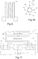
Figure 9 shows a top plan view of a component of the embodiment shown inFigure 8 ; -
Figure 10 shows a circuit diagram formed by components of the embodiment shown inFigure 8 ; -
Figure 11 shows a block diagram of a MEMS system that includes the embodiment shown inFigure 8 ; and -
Figures 12 and 13 are schematic perspective views of portable apparatuses that incorporate the present projective system. - The present invention is described in what follows, purely by way of example, with reference to the case of a MEMS device designed to reflect an optical beam in an electronically controllable way, and thus including at least one mirror. However possible are other uses of the MEMS device described hereinafter.
- This being said,
Figure 1 shows aprojective system 2, which includes alight source 4 formed by a plurality ofdiodes 6 of a laser or LED type, each of which emits electromagnetic radiation at a corresponding wavelength. For example, inFigure 1 threediodes 6 are shown, each of which emits radiation, respectively, around red (620-750 nm), green (495-570 nm), and blue (450-475 nm). - The
projective system 2 further comprises acombiner 8, aMEMS system 10, and adisplay 12. Thecombiner 8 is arranged downstream of thelight source 4 so as to receive the electromagnetic radiation emitted by thediodes 6 and form a single optical beam OB1, obtained by combination of this electromagnetic radiation. Thecombiner 8 is further designed to direct the optical beam OB1 on theMEMS system 10. In turn, theMEMS system 10, described in greater detail hereinafter, is designed to generate a reflected optical beam OB2 and to send the reflected optical beam OB2 onto thedisplay 12 so as to enable formation of images on thedisplay 12. - In detail, the
MEMS system 10 is designed to vary in time the orientation in space of the axis of the reflected optical beam OB2 so as to scan periodically portions of thedisplay 12. - The
MEMS system 10 comprises a MEMS device 11 (shown inFigures 2 and3 ), which is formed in afirst die 20 and includes a fixed supportingbody 22 of semiconductor material (for example, silicon), which defines acavity 24. - The
MEMS device 11 further comprises a suspendedstructure 26, which is constrained, at its own ends, to the fixed supportingbody 22 and is suspended over thecavity 24. - The suspended
structure 26 comprises adeformable structure 27 and aninternal structure 29, which are of semiconductor material. - In detail, the
deformable structure 27 comprises a first arm B1 and a second arm B2, which are physically distinct, have elongated shapes, are arranged around theinternal structure 29 and in particular extend in cantilever fashion between the fixed supportingbody 22 and theinternal structure 29. Each of the first and second arms B1, B2 is deformable and functions as spring, this spring being principally subjected to deflection (secondarily, also to torsion), as described hereinafter. - Without any loss of generality, in the embodiment shown in
Figures 2 and3 , theinternal structure 29 comprises a frame-like portion 36, acentral portion 38, and two connectingportions 40. In top plan view, the frame-like portion 36 has a ring shape (for example, the shape of an annulus). Thecentral portion 38 extends within the frame-like portion 36, to which it is connected via the two connectingportions 40. Thecentral portion 38 has, for example, a circular shape, in top plan view, and is designed to carry a mirror 41 (shown only inFigure 3 ), which is formed, for example, by a metal film and is designed to receive the optical beam OB1 coming from thecombiner 8 and to generate the reflected optical beam OB2. - To a first approximation, the
central portion 38, the frame-like portion 36, and the two connectingportions 40 form a rigid body. Further, the frame-like portion 36 functions as rotatable frame, as described hereinafter. - In greater detail, in what follows we assume an (oriented) axis H and an axis Z, which are perpendicular to one another and define a plane parallel to the main surface of the
first die 20. We further assume a further axis K, perpendicular to the axes H and Z and passing through the geometrical centre of thecentral portion 38 of theinternal structure 29. In what follows, the axis K will be referred to as "axis of symmetry K". - This being said, without any loss of generality, the connecting
portions 40 extend along the axis H, starting from opposite points of thecentral portion 38. - As regards the
deformable structure 27, in resting conditions the first and second arms B1, B2 extend parallel to the plane HZ. Further, each of them is fixed to the fixed supportingbody 22 in a corresponding single area of the latter, as explained in what follows. - In greater detail, each of the first and second arms B1, B2 comprises a respective elongated portion (designated respectively by 30 and 32), which has a curved shape with single concavity, with concavity facing the
internal structure 29, and in particular the frame-like portion 36 of theinternal structure 29, which is located in a portion of space defined by the concavities of the first and secondelongated portions like portion 36 of theinternal structure 29 extend within the recesses formed by the concavities of the first and secondelongated portions - Without any loss of generality, in top plan view the first
elongated portion 30 extends in a first half-plane defined by the axis Z, whereas the secondelongated portion 32 extends in the other half-plane defined by the axis Z. - Each of the first and second
elongated portions body 22. Assuming a cylindrical reference system centred on the axis of symmetry K, the first ends of the first and secondelongated portions elongated portion 30 may have an angular coordinate, measured with respect to the axis Z, for example of 30°. - Each of the first and second
elongated portions internal structure 29, as described in greater detail hereinafter. Without any loss of generality, the second ends of the first and secondelongated portions elongated portion 30 may have an angular coordinate for example of 150°. - In other words, the first ends of the first and second
elongated portions elongated portions like portion 36 are surrounded laterally, and at a distance, by the first and secondelongated portions - In greater detail, each of the first and second
elongated portions - Without any loss of generality, each line of symmetry L1, L2 is formed by a portion of a corresponding spiral (i.e., with radius of curvature that decreases, or at the most is locally constant, as the angular coordinate increases) that winds around the axis of symmetry K, and thus reduces its own distance from the axis of symmetry K as the angular coordinate increases. Further, the lines of symmetry L1, L2 extend on corresponding angular domains, which have amplitudes smaller than 180°, do not overlap, and are respectively equal, for example, to [30°, 150°] and [210°, 330°].
- In addition, without any loss of generality, considering each of the first and second
elongated portions - Once again without any loss of generality, the first and second
elongated portions - As may be seen in
Figure 2 , the second ends of the first and secondelongated portions like portion 36 of theinternal structure 29, by interposition of corresponding terminal portions. - In particular, the first and second arms B1, B2 comprise, respectively, a first
terminal portion 31 and a secondterminal portion 33. Further, the second end of the firstelongated portion 30 is connected to a first end of the firstterminal portion 31, which forms a single piece with the firstelongated portion 30. A second end of the firstterminal portion 31 is connected to a corresponding point of the frame-like portion 36 of theinternal structure 29, which lies along the axis Z. - The second end of the second
elongated portion 32 is connected to a first end of thesecond terminal portion 33, which forms a single piece with the secondelongated portion 32. A second end of thesecond terminal portion 33 is connected to a corresponding point of the frame-like portion 36, which lies along the axis Z and is diametrically opposite with respect to the point of the frame-like portion 36 where the firstterminal portion 31 connects up. - Without any loss of generality, the first and second
terminal portions - In greater detail, and without any loss of generality, each of the first and second
terminal portions terminal portions internal structure 29 being arranged on the outside of said concavities. - In addition, the line of symmetry of each of the first and second
terminal portions - In other words, if we denote as "first gap I1" the gap delimited by the frame-
like portion 36, by the firstelongated portion 30, and by the firstterminal portion 31, this first gap I1 forms a sort of first eyelet O1 delimited in part by the firstterminal portion 31. Further, the first gap I1 includes a respective portion, which is delimited by the firstelongated portion 30 and by the frame-like portion 36 and has a width that decreases monotonically as the angular coordinate increases, as far as the second end of the firstelongated portion 30, where it connects to the aforementioned eyelet O1 The same considerations apply for a second gap I2, which is delimited by the secondelongated portion 32 and which forms asecond eyelet 02. - In practice, each one of the first and second
terminal portions - To a first approximation, the suspended
structure 26 thus has the conformation of a spiral galaxy (in top plan view), where the second ends of the arms, fixed to theinternal structure 29, are arranged in a same direction of rotation (counter clockwise) with respect to the corresponding first ends of the arms, fixed to the fixed supportingstructure 22. This enables reduction of the area of theMEMS device 11, albeit guaranteeing application of a high force of actuation on theinternal structure 29, as described hereinafter. - In detail, movement of the rotating element of the
internal structure 29 is obtained thanks to the presence of piezoelectric elements. In this connection, theMEMS device 11 comprises a firstpiezoelectric element 50, a secondpiezoelectric element 52, a thirdpiezoelectric element 54, and a fourthpiezoelectric element 56, which are of piezoelectric material, for example, lead zirconate titanate (PZT) or aluminium nitride (AlN). - The first and third
piezoelectric elements elongated portion 30, whereas the second and fourthpiezoelectric elements elongated portion 32. In this connection, inFigure 2 portions of theMEMS device 11 have been removed in order to facilitate understanding of the arrangement of the piezoelectric elements. Part of the removed elements is visible inFigure 3 . - In detail, the first and third
piezoelectric elements piezoelectric element 50 is entirely located in the left-hand half-plane, with respect to the axis H, whereas the thirdpiezoelectric element 54 has a secondary portion, which is also located in the left-hand half-plane, and a main portion, which is located in the right-hand half-plane. - The second and fourth
piezoelectric elements piezoelectric elements piezoelectric elements piezoelectric element 52 is located at a greater angular coordinate than the fourthpiezoelectric element 56. Further, in top plan view and in resting conditions, the secondpiezoelectric element 52 is located entirely in the right-hand half-plane, with respect to the axis H, whereas the fourthpiezoelectric element 56 has a secondary portion, which is also located in the right-hand half-plane, and a main portion, which is located in the left-hand half-plane. - In greater detail, as visible in
Figure 3 , theMEMS device 11 comprises a firstdielectric region 60 and a seconddielectric region 62, which extend, respectively, over the first and secondelongated portions - Further, the
MEMS device 11 comprises a firstbottom electrode 64 and a secondbottom electrode 66, which are made, for example, of titanium and extend respectively over the first and seconddielectric regions piezoelectric elements bottom electrode 64, with which they are in direct contact, whereas the second and fourthpiezoelectric elements second bottom electrode 66, with which they are in direct contact. - The
MEMS device 11 further comprises, for each piezoelectric element, a respective top electrode, made, for example, of platinum and overlying, in direct contact, the respective piezoelectric element. In this connection, inFigure 3 a firsttop electrode 68 and a secondtop electrode 70 are visible, which are arranged respectively on the third and fourthpiezoelectric elements - The
MEMS device 11 further comprises adielectric coating 72, which extends over the top electrodes, as well as over the exposed portions of the piezoelectric elements and of the bottom electrodes. In order to enable the electrical contacts with the first and secondbottom electrodes MEMS device 11 comprises a first bottom-electrode metallization 74 and a second bottom-electrode metallization 76, which extend through thedielectric coating 72 and contact the first and secondbottom electrodes MEMS device 11 comprises, for each top electrode, a corresponding top-electrode metallization. In this connection, inFigure 3 a first top-electrode metallization 78 and a second top-electrode metallization 80 are visible, which extend through thedielectric coating 72 and contact, respectively, the first and secondtop electrodes - As shown in
Figure 4 , theMEMS system 10 further comprises asecond die 102, formed inside which is a drivingcircuit 104, which is electrically connected to the first, second, third, and fourthpiezoelectric elements - In use, the driving
circuit 104 applies on the first and fourthpiezoelectric elements 50, 56 a first control signal, of an a.c. type, and further applies on the second and thirdpiezoelectric elements 52, 54 a second control signal, which is also of an a.c. type and is phase-shifted by 180° with respect to the first control signal. In this way, it may be shown that thedeformable structure 27 undergoes a periodic deformation, such as to cause a rotation of theinternal structure 29, and in particular of itscentral portion 38, about a first axis of rotation that lies in the plane HZ and is comprised between the axes H and Z. An example of the deformation undergone by thedeformable structure 27 at a given instant is shown inFigure 5 . In general, the exact position of the first axis of rotation depends upon the angular arrangement of the first ends of the first and secondelongated portions terminal portions like portion 36. - In greater detail, the
internal structure 29, in so far as it is a mechanical structure, exhibits a certain number of modes of oscillation, which on the other hand can be studied analytically and/or experimentally and/or numerically. Further, it may be shown that the first, second, third, and fourthpiezoelectric elements elongated portions internal structure 29, and thus of themirror 41, the energy supplied to the piezoelectric elements to obtain this rotation is reduced, thus optimizing consumption. - According to a different embodiment, shown in
Figure 6 , thedeformable structure 27 of theMEMS device 11 comprises a third arm B3 and a fourth arm B4, which in turn comprise, respectively, a thirdelongated portion 90 and a fourthelongated portion 92. - In detail, in
Figure 6 the angular domains of the first and secondelongated portions Figure 6 shows the angular domains of the third and fourthelongated portions - In greater detail, the third and fourth
elongated portions elongated portions elongated portions elongated portions elongated portions - Each of the third and fourth
elongated portions body 22. Without any loss of generality, the first ends of the third and fourthelongated portions elongated portions 30, 32) and have angular coordinates that differ by 180° from one another. Once again without any loss of generality, the first end of the thirdelongated portion 90 has an angular coordinate comprised between the angular coordinates of the first and second ends of the firstelongated portion 30, whereas the first end of the fourthelongated portion 92 has an angular coordinate comprised between the angular coordinates of the first and second ends of the secondelongated portion 32. - Each of the third and fourth
elongated portions internal structure 29, as described in greater detail hereinafter. Without any loss of generality, the second ends of the third and fourthelongated portions elongated portion 90 has an angular coordinate comprised between the angular coordinates of the second end of the firstelongated portion 30 and of the first end of the secondelongated portion 32, whereas the second end of the fourthelongated portion 92 has an angular coordinate comprised between the angular coordinates of the second end of the secondelongated portion 32 and of the first end of the firstelongated portion 30. - In practice, the angular domains of the third and fourth arms B3, B4 overlap respectively, for at least 50%, the angular domains of the first and second arms B1, B2.
- In greater detail, each of the third and fourth
elongated portions elongated portions elongated portions - Once again without any loss of generality, the third and fourth
elongated portions - The second ends of the third and fourth
elongated portions like portion 36 of theinternal structure 29, by interposition of corresponding terminal portions (not indicated), which are angularly arranged at a distance apart by 180°. - The
MEMS device 11 further comprises a fifthpiezoelectric element 95, a sixthpiezoelectric element 96, a seventhpiezoelectric element 97, and an eighthpiezoelectric element - The fifth and seventh
piezoelectric elements elongated portion 90, whereas the sixth and eighthpiezoelectric elements elongated portion 92. Further, the fifth and eighthpiezoelectric elements piezoelectric elements - In practice, the embodiment shown in
Figure 6 makes it possible to exert a greater force on theinternal structure 29, as well as to increase the frequency of rotation, thanks to the presence of a number of deformable elements that operate in parallel. In this connection, albeit not shown, embodiments are in any case possible with an even greater number of arms and/or piezoelectric elements. - According to a different embodiment, shown in
Figure 7 , the internal structure (here designated by 109) again comprises the frame-like portion (of a hollow type), here designated by 136, which will be referred to in what follows as "outer frame 136". - Extending within the cavity defined by the
outer frame 136 are: a further deformable structure including a pair further arms, which will be referred to in what follows as first and second secondary arms SB1, SB2; aninner frame 170; and a supportingportion 138, designed to carry the mirror 41 (not shown inFigure 7 ). The first and second secondary arms SB1, SB2 comprise, respectively, a first secondaryelongated portion 160 and a second secondaryelongated portion 162, as well as, respectively, a firstsecondary terminal portion 131 and a secondsecondary terminal portion 133. - In greater detail, the supporting
portion 138 connects up to theinner frame 170 by connecting portions (not associated to reference numbers inFigure 7 ), in a way similar to what has been described as regards the frame-like portion 36 and thecentral portion 38. - The first and second secondary
elongated portions - In greater detail, each of the first and second secondary
elongated portions inner frame 170, which is located in a portion of space defined by the concavities of the first and second secondaryelongated portions inner frame 170 has an annular shape, with circular outer perimeter, in top plan view. Further, parts of theinner frame 170 extend within the recesses formed by the concavities of the first and second secondaryelongated portions - Each of the first and second secondary
elongated portions outer frame 136. Without any loss of generality, the first ends of the first and second secondaryelongated portions elongated portions elongated portions 30, 32 (in this embodiment, the latter have angular coordinates approximately equal to 60° and 240°). - Each of the first and second secondary
elongated portions inner frame 170, as described in greater detail hereinafter. Without any loss of generality, the second ends of the first and second secondaryelongated portions - In greater detail, each of the first and second secondary
elongated portions elongated portions inner frame 170, respectively, by interposition of the first and second secondaryterminal portions terminal portions inner frame 170, which are angularly arranged at a distance apart from one another by 180° and further angularly staggered by 90° with respect to the points in which the first and secondterminal portions outer frame 136. - As regards the shape of the first and second secondary
terminal portions terminal portions - In the embodiment shown in
Figure 7 , theMEMS device 11 also comprises the fifth, sixth, seventh, and eighthpiezoelectric elements - The fifth and seventh
piezoelectric elements elongated portion 160, whereas the sixth and eighthpiezoelectric elements elongated portion 162. In particular, as regards the arrangement of the fifth, sixth, seventh, and eighthpiezoelectric elements elongated portions piezoelectric elements elongated portions - The fifth and eighth
piezoelectric elements piezoelectric elements - The third and fourth control signals are of an a.c. type and can be generated by the driving
circuit 104, so as to be phase-shifted with respect to one another by 180°. Further, the third and fourth control signals may have a frequency and/or amplitude different from the first and second control signals. - In practice, the first and second
elongated portions elongated portions - Once again with reference to the embodiment shown in
Figure 7 , without any loss of generality, the first and second secondaryelongated portions elongated portions - Operatively, the first, second, third, and fourth
piezoelectric elements elongated portions outer frame 136 about the aforementioned first axis of rotation, with respect to the fixed supportingbody 22. Further, the fifth, sixth, seventh, and eighthpiezoelectric elements elongated portions inner frame 170 about a second axis of rotation (not shown), which is perpendicular to the first axis of rotation and lies in the plane HZ (strictly speaking, this applies to the case of absence of deformations). Rotation of theinner frame 170 entails simultaneous rotation of the supportingportion 138, which forms substantially a rigid body with theinner frame 170. - It follows that, with respect to the fixed supporting
body 22, the supportingportion 138, which carries themirror 41, can turn about two axes orthogonal to one another. In this case, theprojective system 2 is of a biaxial type. - In general, all the embodiments described may include one or more strain gauges, as shown in
Figure 8 with reference, purely by way of example, to the embodiment shown inFigure 2 . - In detail, the
MEMS device 11 comprises afirst strain gauge 300, asecond strain gauge 302, athird strain gauge 304, and afourth strain gauge 306, each of which is formed, for example, by a metal serpentine 310 (made, for example, of platinum), shown inFigure 9 . The serpentine may be formed during the process flow of theMEMS device 11, for example during the steps of formation of the electrodes. - Once again with reference to
Figure 8 , the first and second strain gauges 300, 302 are arranged, respectively, on the first end of the firstelongated portion 30 and on the first end of the secondelongated portion 32, in a symmetrical way (with central symmetry) with respect to the axis of symmetry K. The third and fourth strain gauges 304, 306 are instead arranged on the fixed supportingbody 22, in a symmetrical way (with central symmetry) with respect to the axis of symmetry K. - The
MEMS device 11 further comprises conductive paths (not shown), which connect the strain gauges so that they form aWheatstone bridge 312, shown inFigure 10 , where the strain gauges are modelled as equivalent resistors. - In detail, a first terminal and a second terminal of the
first strain gauge 300 form, respectively, a node N1 and a node N2. A first terminal of thesecond strain gauge 302 is connected to the node N1, whereas the second terminal forms a node N3. A first terminal of thethird strain gauge 304 is connected to the node N3, whereas the second terminal forms a node N4. The first and second terminals of thefourth strain gauge 306 are connected, respectively, to the node N2 and to the node N4. - In practice, the third and fourth strain gauges 304, 306 function as reference resistors, because the respective resistances do not depend upon the angular position of the
internal structure 29. Instead, the resistances of the first and second strain gauges 300, 302 are the same as one another in the absence of rotation of theinternal structure 29, whereas, when theinternal structure 29 rotates, they undergo deviations that are the same in modulus, but have opposite signs, these deviations being proportional to the degree of the rotation. This occurs because the first and second strain gauges 300, 302 are arranged on symmetrical portions of elongated portions, which, when thedeformable structure 27 undergoes deformation, are subjected to out-of-plane displacements with approximately the same amplitude, but opposite signs. These symmetrical portions thus exert on the strain gauges opposite tensile stresses of approximately the same intensity. - As shown in
Figure 11 , in thesecond die 102 there may be formed, in addition to thedriving circuit 104, acontrol circuit 108, which is electrically coupled to theWheatstone bridge 312 and to thedriving circuit 104. - In detail, the
control circuit 108 is configured to generate a signal indicating the angular position of theinternal structure 29, as a function of the resistances of theWheatstone bridge 312. Further, thecontrol circuit 108 controls the drivingcircuit 104 as a function of the signal indicating the angular position; i.e., it controls the first and second control signals so as to optimize the driving in frequency and amplitude, i.e., so as to obtain the desired angular deflection. - As illustrated in
Figure 12 , theprojective system 2 may be obtained as separate and stand-alone accessory with respect to an associated portableelectronic apparatus 200, such as a cellphone or smartphone (or else, for example, a PDA, a tablet, a digital audio player, or a controller for videogames), being coupled to a same portableelectronic apparatus 200 by appropriate electrical and mechanical connection elements (not illustrated). In this case, theprojective system 2 is provided with anown package 201, which has at least oneportion 202 transparent to the reflected optical beam OB2 generated by theMEMS reflector 8. Thepackage 201 of theprojective system 2 is releasably coupled to arespective case 203 of the portableelectronic apparatus 200. - Alternatively, as illustrated in
Figure 13 , theprojective system 2 may be integrated within the portableelectronic apparatus 200, being arranged within thecase 203 of the portableelectronic apparatus 200 itself, which has in this case arespective portion 204 transparent to the reflected optical beam OB2 generated by theMEMS reflector 8. In this case, theprojective system 2 is, for example, coupled to a printed-circuit board present within thecase 203 of the portableelectronic apparatus 200. - From what has been described and illustrated previously, the advantages that the present solution affords emerge clearly.
- In particular, the present MEMS device is characterized by reduced overall dimensions, thanks to the fact that the deformable arms that carry the actuators, i.e., the piezoelectric elements, form concavities that house part of the internal structures.
- In conclusion, it is clear that modifications and variations may be made to what has been described and illustrated herein, without thereby departing from the scope of the present invention, as defined in the annexed claims.
- For example, the terminal portions of the arms may have shapes different from what has been described.
- As regards the elongated portions of the arms, they may extend on angular domains different from what has been illustrated.
- In general, the angular domains of the first and second elongated portions have amplitudes comprised in the interval [60°, 170°], or else in the interval [90°, 150°], as also the angular domains of the first and second secondary elongated portions, if present. Further, the elongated portions of the arms may have more than one concavity and/or convex regions facing the internal structure. In general, the course of the lines of symmetry of the arms may thus be more irregular than what has been described, as likewise the angular arrangements of the respective ends. Further, the arms have angular domains with amplitudes comprised in the interval [65°, 175°], or else in the interval [95°, 155°]. In addition, the angular domains of the first and second arms B1, B2 are preferably disjoint so that the area occupied by the
MEMS device 11 is particularly reduced. Similar considerations apply for the pairs formed by the third and fourth arms B3, B4 and by the first and second secondary arms SB1, SB2, if present. - As regards the
internal structure 29, the frame-like portion 36 may be of a full type, instead of being hollow, in which case it functions ascentral portion 38 and carries themirror 41, the connectingportions 40 being absent. Likewise, theinner frame 170 may be replaced by a full structure, which functions as supportingportion 138 and carries themirror 41. - As regards the number of piezoelectric elements coupled to each arm, it may differ from the one described. For example, on each arm there may be present just one piezoelectric element, which has a shape different from that of the piezoelectric element present on the other arm.
- As regards the
central portion 38 and the supportingportion 138, they may have shapes different from what has been described; for example, they may include shapings designed to increase stiffness. - Finally, the present device may be obtained using one or more metal materials (e.g., aluminium or steel), instead of semiconductor material.
Claims (20)
- A MEMS device comprising a fixed structure (22) delimiting a cavity (24) and a suspended structure (26), which overlies the cavity and comprises:- an internal structure (29;109); and- at least one first arm (B1) and one second arm (B2), which are arranged around the internal structure and each of which has a respective first end and a respective second end, said first ends being fixed to the fixed structure and being angularly arranged at a distance apart, said second ends being fixed to the internal structure, being angularly arranged at a distance apart and being angularly arranged in a same direction of rotation with respect to the corresponding first ends; and- a number of piezoelectric actuators (50, 52, 54, 56), each of which is coupled to the first arm or to the second arm and can be driven so as to cause a deformation of the arm to which it is coupled and a consequent rotation of the internal structure;and wherein, in resting conditions, each of the first and second arms has a respective elongated portion (30, 32) with a respective concavity, said internal structure extending in part within the concavities of the elongated portions of the first and second arms.
- The MEMS device according to claim 1, wherein, in resting conditions, said first and second arms (B1, B2) extend around the internal structure (29) on angular domains at least in part shifted and with amplitude comprised in the interval [65°, 175°].
- The MEMS device according to claim 2, wherein the angular domains of the first and second arms (B1, B2) are disjoint.
- The MEMS device according to any one of the preceding claims, wherein the second ends of the first and second arms (B1, B2) are arranged at an angular distance of 180°.
- The MEMS device according to any one of the preceding claims, wherein the first ends of the first and second arms (B1, B2) are arranged at an angular distance of 180°.
- The MEMS device according to any one of the preceding claims, wherein, in resting conditions, the first and second elongated portions (30, 32) form, each, a single concavity.
- The MEMS device according to claim 6, wherein each of the first and second elongated portions (30, 32) has a respective line of symmetry, which has a radius of curvature that varies angularly in a monotonic way.
- The MEMS device according to claim 6 or claim 7, wherein the width of each of the first and second elongated portions (30, 32) decreases in the direction of the second end of the corresponding arm (B1, B2).
- The MEMS device according to any one of claims 6 to 8, wherein the first and second elongated portions (30, 32) form, respectively, the first ends of the first and second arms (B1, B2); and wherein the first and second arms further comprise, respectively, a first terminal portion (31) and a second terminal portion (33), which form, respectively, the second ends of the first and second arms; and wherein the first and second terminal portions connect, respectively, to corresponding parts of the first and second elongated portions and form curved projections with single concavity, with concavity facing the internal structure (29), said curved projections projecting radially with respect to said parts of the first and second elongated portions.
- The MEMS device according to any one of the preceding claims, wherein each of said piezoelectric actuators (50, 52, 54, 56) is arranged on the elongated portion of the arm (B1, B2) to which it is coupled.
- The MEMS device according to claim 10, comprising a first piezoelectric actuator (50), a second piezoelectric actuator (52), a third piezoelectric actuator (54), and a fourth piezoelectric actuator (56), the first and third piezoelectric actuators being arranged on the elongated portion (30) of the first arm (B1), the second and fourth piezoelectric actuators being arranged on the elongated portion (52, 56) of the second arm (B2), in a way symmetrical, respectively, to the first and second piezoelectric actuators.
- The MEMS device according to any one of the preceding claims, further comprising a third arm (B3) and a fourth arm (B4), each of which comprises a respective elongated portion (90, 92), each of which has a respective concavity; and wherein, in resting conditions, the elongated portions (30, 32) of the first and second arms extend at least in part within the concavities formed, respectively, by the elongated portions of the third and fourth arms.
- The MEMS device according to any one of the preceding claims, wherein said internal structure (29) comprises:- a nested structure (138, 160, 162, 170); and- an outer frame (136) of an annular shape, which surrounds the nested structure, and fixed to which are the second ends of the first and second arms (B1, B2);and wherein the nested structure comprises:- an inner frame (170); and- a first secondary arm (SB1) and a second secondary arm (SB2), which are arranged around the inner frame and each of which has a respective first end and a respective second end, said first ends being fixed to the outer frame and being angularly arranged at a distance apart, said second ends being fixed to the inner frame, being angularly arranged at a distance apart, and being arranged angularly in a same direction of rotation with respect to the corresponding first ends; and- a number of additional piezoelectric actuators (95, 96, 97, 98), each of which is coupled to the first secondary arm or to the second secondary arm and can be driven so as to cause a deformation of the secondary arm to which it is coupled and a consequent rotation of the inner frame;and wherein each of the first and second secondary arms comprises a respective elongated portion (160, 162) with a respective concavity; and wherein, in resting conditions, said inner frame extends in part within the concavities of the elongated portions of the first and second secondary arms.
- The MEMS device according to any one of the preceding claims, further comprising at least one first strain gauge (300) and one second strain gauge (302), which are mechanically coupled, respectively, to the first and second arms (B1, B2), in symmetrical positions.
- The MEMS device according to any one of the preceding claims, wherein said fixed structure (22) and said internal structure (29) are made at least in part of semiconductor material.
- A projective MEMS system comprising:- the MEMS device (11) according to any one of the preceding claims, said MEMS device further comprising a reflecting element (41) coupled to the internal structure (29) ; and- an optical source (4) configured to generate an optical beam (OBI) that impinges on the reflecting element.
- A portable electronic apparatus (200) comprising a projective MEMS system (2) according to claim 16.
- The apparatus according to claim 17, wherein said projective MEMS system (2) is a stand-alone accessory having a package (201) releasably coupled to a respective case (203) of said portable electronic apparatus (200).
- The apparatus according to claim 17, wherein said projective MEMS system (2) is formed in an integrated way, within a case (203) of said portable electronic apparatus (200).
- A method for controlling a MEMS device according to claim 11, wherein the first and second piezoelectric actuators (50, 52) are arranged angularly in a same direction of rotation with respect to the third and fourth piezoelectric actuators (54, 56), respectively, said method comprising the steps of:- applying to the first and fourth piezoelectric actuators a first control signal; and- applying to the second and third piezoelectric actuators a second control signal, which is phase-shifted by 180° with respect to the first control signal.
Applications Claiming Priority (1)
| Application Number | Priority Date | Filing Date | Title |
|---|---|---|---|
| IT102016000131849A IT201600131849A1 (en) | 2016-12-28 | 2016-12-28 | MEMS DEVICE WITH PIEZOELECTRIC DRIVE, PROJECTIVE MEMS SYSTEM INCLUDING THE MEMS DEVICE AND ITS COMMAND METHOD |
Publications (2)
| Publication Number | Publication Date |
|---|---|
| EP3343265A1 true EP3343265A1 (en) | 2018-07-04 |
| EP3343265B1 EP3343265B1 (en) | 2024-02-28 |
Family
ID=58609911
Family Applications (1)
| Application Number | Title | Priority Date | Filing Date |
|---|---|---|---|
| EP17172096.4A Active EP3343265B1 (en) | 2016-12-28 | 2017-05-19 | A mems device with piezoelectric actuation, a projective mems system including the mems device and related control method |
Country Status (4)
| Country | Link |
|---|---|
| US (1) | US10310253B2 (en) |
| EP (1) | EP3343265B1 (en) |
| CN (2) | CN207318836U (en) |
| IT (1) | IT201600131849A1 (en) |
Cited By (3)
| Publication number | Priority date | Publication date | Assignee | Title |
|---|---|---|---|---|
| WO2020205373A1 (en) * | 2019-04-02 | 2020-10-08 | Microsoft Technology Licensing, Llc | Display device with compact scanning mirror |
| WO2020214368A1 (en) * | 2019-04-15 | 2020-10-22 | Microsoft Technology Licensing, Llc | Mems scanner |
| EP3882683A1 (en) * | 2020-03-16 | 2021-09-22 | Ricoh Company, Ltd. | Movable device, image projection apparatus, object recognition device, and mobile object |
Families Citing this family (13)
| Publication number | Priority date | Publication date | Assignee | Title |
|---|---|---|---|---|
| IT201600131849A1 (en) * | 2016-12-28 | 2018-06-28 | St Microelectronics Srl | MEMS DEVICE WITH PIEZOELECTRIC DRIVE, PROJECTIVE MEMS SYSTEM INCLUDING THE MEMS DEVICE AND ITS COMMAND METHOD |
| IT201900004197A1 (en) | 2019-03-22 | 2020-09-22 | St Microelectronics Srl | INTEGRATED ELECTRONIC MODULE FOR 3D DETECTION, AND 3D SCANNING DEVICE INCLUDING THE ELECTRONIC MODULE |
| CN215974953U (en) * | 2020-05-07 | 2022-03-08 | 意法半导体股份有限公司 | MEMS actuator, flow regulator and speaker |
| CN116057449B (en) * | 2020-08-04 | 2025-09-30 | 富士胶片株式会社 | Micromirror device and optical scanning device |
| JP7436686B2 (en) * | 2020-09-04 | 2024-02-22 | 富士フイルム株式会社 | Micromirror device and optical scanning device |
| IT202000022715A1 (en) | 2020-09-25 | 2022-03-25 | St Microelectronics Srl | INTEGRATED ELECTRONIC MODULE INCLUDING TWO MICROMIRRORS, AND SYSTEM THAT INCLUDE THE ELECTRONIC MODULE |
| WO2022102214A1 (en) * | 2020-11-11 | 2022-05-19 | パナソニックIpマネジメント株式会社 | Driving element and driving device |
| JP2023008577A (en) * | 2021-07-06 | 2023-01-19 | スタンレー電気株式会社 | Light deflector |
| DE102021208125A1 (en) | 2021-07-28 | 2023-02-02 | Robert Bosch Gesellschaft mit beschränkter Haftung | Process for controlling a piezoelectric drive unit |
| EP4202529A1 (en) * | 2021-12-22 | 2023-06-28 | Silicon Austria Labs GmbH | Optical deflector and method operating an optical deflector |
| IT202200004745A1 (en) * | 2022-03-11 | 2023-09-11 | St Microelectronics Srl | MICROELECTROMECHANICAL BIAXIAL MIRROR DEVICE WITH PIEZOELECTRIC ACTUATION |
| IT202400014038A1 (en) * | 2024-06-19 | 2025-12-19 | St Microelectronics Int Nv | MEMS DEVICE HAVING AN ORIENTABLE STRUCTURE AND QUASI-STATIC PIEZOELECTRIC ACTUATION, IN PARTICULAR MICROSPIRRORING, WITH IMPROVED EFFICIENCY |
| DE102024206030A1 (en) * | 2024-06-27 | 2025-12-31 | Fraunhofer-Gesellschaft zur Förderung der angewandten Forschung eingetragener Verein | Micromechanical device with a semiconductor arrangement for the emission and detection of electromagnetic radiation |
Citations (2)
| Publication number | Priority date | Publication date | Assignee | Title |
|---|---|---|---|---|
| US5519198A (en) * | 1991-10-15 | 1996-05-21 | Gap Technologies, Inc. | Electro-optical scanning system |
| WO2016199730A1 (en) * | 2015-06-09 | 2016-12-15 | 第一精工株式会社 | Movable reflective element and two-dimensional scanning device |
Family Cites Families (8)
| Publication number | Priority date | Publication date | Assignee | Title |
|---|---|---|---|---|
| US6830944B1 (en) * | 1999-03-18 | 2004-12-14 | Trustees Of Boston University | Piezoelectric bimorphs as microelectromechanical building blocks and constructions made using same |
| FR2840102B1 (en) * | 2002-05-23 | 2004-07-16 | Commissariat Energie Atomique | MINIATURE ELECTROSTATIC ACTUATING DEVICE AND INSTALLATION COMPRISING SUCH DEVICES |
| JP4286553B2 (en) * | 2003-02-06 | 2009-07-01 | 日本信号株式会社 | Planar type actuator |
| JP5524254B2 (en) * | 2012-02-14 | 2014-06-18 | 富士フイルム株式会社 | Mirror drive device and control method thereof |
| JP2014137472A (en) * | 2013-01-17 | 2014-07-28 | Funai Electric Co Ltd | Oscillating mirror element and electronic apparatus having projector function |
| JP6092713B2 (en) * | 2013-05-28 | 2017-03-08 | スタンレー電気株式会社 | Optical deflector |
| DE102016208924A1 (en) * | 2016-05-24 | 2017-11-30 | Robert Bosch Gmbh | Micromechanical component and method for adjusting an adjustable part simultaneously about two mutually inclined axes of rotation |
| IT201600131849A1 (en) * | 2016-12-28 | 2018-06-28 | St Microelectronics Srl | MEMS DEVICE WITH PIEZOELECTRIC DRIVE, PROJECTIVE MEMS SYSTEM INCLUDING THE MEMS DEVICE AND ITS COMMAND METHOD |
-
2016
- 2016-12-28 IT IT102016000131849A patent/IT201600131849A1/en unknown
-
2017
- 2017-05-12 US US15/594,287 patent/US10310253B2/en active Active
- 2017-05-19 EP EP17172096.4A patent/EP3343265B1/en active Active
- 2017-05-31 CN CN201720623732.5U patent/CN207318836U/en active Active
- 2017-05-31 CN CN201710401489.7A patent/CN108249382A/en active Pending
Patent Citations (2)
| Publication number | Priority date | Publication date | Assignee | Title |
|---|---|---|---|---|
| US5519198A (en) * | 1991-10-15 | 1996-05-21 | Gap Technologies, Inc. | Electro-optical scanning system |
| WO2016199730A1 (en) * | 2015-06-09 | 2016-12-15 | 第一精工株式会社 | Movable reflective element and two-dimensional scanning device |
Non-Patent Citations (1)
| Title |
|---|
| U. BARAN: "Resonant PZT MEMS Scanner for High-Resolution Displays", JOURNAL OF MICRO-ELECTRO-MECHANICAL SYSTEMS, vol. 21, no. 6, pages 1303 - 1310, XP011482665, DOI: doi:10.1109/JMEMS.2012.2209405 |
Cited By (8)
| Publication number | Priority date | Publication date | Assignee | Title |
|---|---|---|---|---|
| WO2020205373A1 (en) * | 2019-04-02 | 2020-10-08 | Microsoft Technology Licensing, Llc | Display device with compact scanning mirror |
| US11360299B2 (en) | 2019-04-02 | 2022-06-14 | Microsoft Technology Licensing, Llc | Display device with compact scanning mirror |
| WO2020214368A1 (en) * | 2019-04-15 | 2020-10-22 | Microsoft Technology Licensing, Llc | Mems scanner |
| US11221478B2 (en) | 2019-04-15 | 2022-01-11 | Microsoft Technology Licensing, Llc | MEMS scanner |
| US20220113534A1 (en) * | 2019-04-15 | 2022-04-14 | Microsoft Technology Licensing, Llc | Mems scanner |
| US12124027B2 (en) * | 2019-04-15 | 2024-10-22 | Microsoft Technology Licensing, Llc | MEMS scanner |
| EP3882683A1 (en) * | 2020-03-16 | 2021-09-22 | Ricoh Company, Ltd. | Movable device, image projection apparatus, object recognition device, and mobile object |
| US11640053B2 (en) | 2020-03-16 | 2023-05-02 | Ricoh Company, Ltd. | Movable device, image projection apparatus, heads-up display, laser headlamp, head-mounted display, object recognition device, and mobile object |
Also Published As
| Publication number | Publication date |
|---|---|
| US20180180873A1 (en) | 2018-06-28 |
| EP3343265B1 (en) | 2024-02-28 |
| CN108249382A (en) | 2018-07-06 |
| US10310253B2 (en) | 2019-06-04 |
| CN207318836U (en) | 2018-05-04 |
| IT201600131849A1 (en) | 2018-06-28 |
Similar Documents
| Publication | Publication Date | Title |
|---|---|---|
| EP3343265B1 (en) | A mems device with piezoelectric actuation, a projective mems system including the mems device and related control method | |
| US11953813B2 (en) | Microelectromechanical device with a structure tiltable by piezoelectric actuation having improved mechanical and electrical characteristics | |
| CN110488486B (en) | Resonant dual-axis MEMS reflector with piezoelectric actuator and projection MEMS system including the same | |
| US10365475B2 (en) | Oscillating structure with piezoelectric actuation, system and manufacturing method | |
| JP6447683B2 (en) | Scanning microelectromechanical reflector system, light detection and ranging (LIDAR) device, and method of operating scanning microelectromechanical reflector system | |
| US10914939B2 (en) | MEMS reflector system | |
| EP3839602B1 (en) | Microelectromechanical mirror device with piezoelectric actuation, having an improved structure | |
| JPWO2018230065A1 (en) | Optical scanning device and adjustment method of optical scanning device | |
| US10534170B2 (en) | MEMS device with piezoelectric actuation, a projective MEMS system including the MEMS device and related driving method | |
| CN107636512B (en) | Movable reflection element and two-dimensional scanning device | |
| JP6506212B2 (en) | Optical deflector and manufacturing method | |
| JPWO2019176204A1 (en) | Optical scanning device and its control method | |
| JP2011069954A (en) | Optical scanner | |
| US20230359022A1 (en) | Deflection device with a mirror for use in scanner technical field | |
| CN112731653A (en) | MEMS scanning mirror and laser projector | |
| CN114326094A (en) | Micro-electromechanical mirror device with flatness error compensation | |
| JP2022146781A (en) | Optical deflector, image projector, head-up display, laser head lamp, head mount display, distance measuring device, and mobile body | |
| JP7667043B2 (en) | Optical Deflector | |
| US12572008B2 (en) | Movable device, projection apparatus, head-up display, laser headlamp, head-mounted display, and object recognition apparatus | |
| JP2023008577A (en) | Light deflector | |
| CN120958365A (en) | Microelectromechanical microscope (MEMS), methods for operating a MEMS, projection equipment, and applications of a MEMS. | |
| CN119948381A (en) | Micromirror device and optical scanning device |
Legal Events
| Date | Code | Title | Description |
|---|---|---|---|
| PUAI | Public reference made under article 153(3) epc to a published international application that has entered the european phase |
Free format text: ORIGINAL CODE: 0009012 |
|
| STAA | Information on the status of an ep patent application or granted ep patent |
Free format text: STATUS: THE APPLICATION HAS BEEN PUBLISHED |
|
| AK | Designated contracting states |
Kind code of ref document: A1 Designated state(s): AL AT BE BG CH CY CZ DE DK EE ES FI FR GB GR HR HU IE IS IT LI LT LU LV MC MK MT NL NO PL PT RO RS SE SI SK SM TR |
|
| AX | Request for extension of the european patent |
Extension state: BA ME |
|
| STAA | Information on the status of an ep patent application or granted ep patent |
Free format text: STATUS: REQUEST FOR EXAMINATION WAS MADE |
|
| 17P | Request for examination filed |
Effective date: 20190102 |
|
| RBV | Designated contracting states (corrected) |
Designated state(s): AL AT BE BG CH CY CZ DE DK EE ES FI FR GB GR HR HU IE IS IT LI LT LU LV MC MK MT NL NO PL PT RO RS SE SI SK SM TR |
|
| STAA | Information on the status of an ep patent application or granted ep patent |
Free format text: STATUS: EXAMINATION IS IN PROGRESS |
|
| 17Q | First examination report despatched |
Effective date: 20211104 |
|
| GRAP | Despatch of communication of intention to grant a patent |
Free format text: ORIGINAL CODE: EPIDOSNIGR1 |
|
| STAA | Information on the status of an ep patent application or granted ep patent |
Free format text: STATUS: GRANT OF PATENT IS INTENDED |
|
| INTG | Intention to grant announced |
Effective date: 20230922 |
|
| GRAS | Grant fee paid |
Free format text: ORIGINAL CODE: EPIDOSNIGR3 |
|
| GRAA | (expected) grant |
Free format text: ORIGINAL CODE: 0009210 |
|
| STAA | Information on the status of an ep patent application or granted ep patent |
Free format text: STATUS: THE PATENT HAS BEEN GRANTED |
|
| AK | Designated contracting states |
Kind code of ref document: B1 Designated state(s): AL AT BE BG CH CY CZ DE DK EE ES FI FR GB GR HR HU IE IS IT LI LT LU LV MC MK MT NL NO PL PT RO RS SE SI SK SM TR |
|
| REG | Reference to a national code |
Ref country code: GB Ref legal event code: FG4D |
|
| REG | Reference to a national code |
Ref country code: CH Ref legal event code: EP |
|
| REG | Reference to a national code |
Ref country code: DE Ref legal event code: R096 Ref document number: 602017079492 Country of ref document: DE |
|
| REG | Reference to a national code |
Ref country code: IE Ref legal event code: FG4D |
|
| REG | Reference to a national code |
Ref country code: LT Ref legal event code: MG9D |
|
| PG25 | Lapsed in a contracting state [announced via postgrant information from national office to epo] |
Ref country code: IS Free format text: LAPSE BECAUSE OF FAILURE TO SUBMIT A TRANSLATION OF THE DESCRIPTION OR TO PAY THE FEE WITHIN THE PRESCRIBED TIME-LIMIT Effective date: 20240628 |
|
| REG | Reference to a national code |
Ref country code: NL Ref legal event code: MP Effective date: 20240228 |
|
| PG25 | Lapsed in a contracting state [announced via postgrant information from national office to epo] |
Ref country code: LT Free format text: LAPSE BECAUSE OF FAILURE TO SUBMIT A TRANSLATION OF THE DESCRIPTION OR TO PAY THE FEE WITHIN THE PRESCRIBED TIME-LIMIT Effective date: 20240228 |
|
| PG25 | Lapsed in a contracting state [announced via postgrant information from national office to epo] |
Ref country code: GR Free format text: LAPSE BECAUSE OF FAILURE TO SUBMIT A TRANSLATION OF THE DESCRIPTION OR TO PAY THE FEE WITHIN THE PRESCRIBED TIME-LIMIT Effective date: 20240529 |
|
| PG25 | Lapsed in a contracting state [announced via postgrant information from national office to epo] |
Ref country code: RS Free format text: LAPSE BECAUSE OF FAILURE TO SUBMIT A TRANSLATION OF THE DESCRIPTION OR TO PAY THE FEE WITHIN THE PRESCRIBED TIME-LIMIT Effective date: 20240528 Ref country code: HR Free format text: LAPSE BECAUSE OF FAILURE TO SUBMIT A TRANSLATION OF THE DESCRIPTION OR TO PAY THE FEE WITHIN THE PRESCRIBED TIME-LIMIT Effective date: 20240228 Ref country code: NL Free format text: LAPSE BECAUSE OF FAILURE TO SUBMIT A TRANSLATION OF THE DESCRIPTION OR TO PAY THE FEE WITHIN THE PRESCRIBED TIME-LIMIT Effective date: 20240228 |
|
| PG25 | Lapsed in a contracting state [announced via postgrant information from national office to epo] |
Ref country code: ES Free format text: LAPSE BECAUSE OF FAILURE TO SUBMIT A TRANSLATION OF THE DESCRIPTION OR TO PAY THE FEE WITHIN THE PRESCRIBED TIME-LIMIT Effective date: 20240228 |
|
| PG25 | Lapsed in a contracting state [announced via postgrant information from national office to epo] |
Ref country code: RS Free format text: LAPSE BECAUSE OF FAILURE TO SUBMIT A TRANSLATION OF THE DESCRIPTION OR TO PAY THE FEE WITHIN THE PRESCRIBED TIME-LIMIT Effective date: 20240528 Ref country code: NO Free format text: LAPSE BECAUSE OF FAILURE TO SUBMIT A TRANSLATION OF THE DESCRIPTION OR TO PAY THE FEE WITHIN THE PRESCRIBED TIME-LIMIT Effective date: 20240528 Ref country code: NL Free format text: LAPSE BECAUSE OF FAILURE TO SUBMIT A TRANSLATION OF THE DESCRIPTION OR TO PAY THE FEE WITHIN THE PRESCRIBED TIME-LIMIT Effective date: 20240228 Ref country code: LT Free format text: LAPSE BECAUSE OF FAILURE TO SUBMIT A TRANSLATION OF THE DESCRIPTION OR TO PAY THE FEE WITHIN THE PRESCRIBED TIME-LIMIT Effective date: 20240228 Ref country code: IS Free format text: LAPSE BECAUSE OF FAILURE TO SUBMIT A TRANSLATION OF THE DESCRIPTION OR TO PAY THE FEE WITHIN THE PRESCRIBED TIME-LIMIT Effective date: 20240628 Ref country code: HR Free format text: LAPSE BECAUSE OF FAILURE TO SUBMIT A TRANSLATION OF THE DESCRIPTION OR TO PAY THE FEE WITHIN THE PRESCRIBED TIME-LIMIT Effective date: 20240228 Ref country code: GR Free format text: LAPSE BECAUSE OF FAILURE TO SUBMIT A TRANSLATION OF THE DESCRIPTION OR TO PAY THE FEE WITHIN THE PRESCRIBED TIME-LIMIT Effective date: 20240529 Ref country code: FI Free format text: LAPSE BECAUSE OF FAILURE TO SUBMIT A TRANSLATION OF THE DESCRIPTION OR TO PAY THE FEE WITHIN THE PRESCRIBED TIME-LIMIT Effective date: 20240228 Ref country code: ES Free format text: LAPSE BECAUSE OF FAILURE TO SUBMIT A TRANSLATION OF THE DESCRIPTION OR TO PAY THE FEE WITHIN THE PRESCRIBED TIME-LIMIT Effective date: 20240228 Ref country code: BG Free format text: LAPSE BECAUSE OF FAILURE TO SUBMIT A TRANSLATION OF THE DESCRIPTION OR TO PAY THE FEE WITHIN THE PRESCRIBED TIME-LIMIT Effective date: 20240228 |
|
| PG25 | Lapsed in a contracting state [announced via postgrant information from national office to epo] |
Ref country code: PL Free format text: LAPSE BECAUSE OF FAILURE TO SUBMIT A TRANSLATION OF THE DESCRIPTION OR TO PAY THE FEE WITHIN THE PRESCRIBED TIME-LIMIT Effective date: 20240228 Ref country code: PT Free format text: LAPSE BECAUSE OF FAILURE TO SUBMIT A TRANSLATION OF THE DESCRIPTION OR TO PAY THE FEE WITHIN THE PRESCRIBED TIME-LIMIT Effective date: 20240628 |
|
| REG | Reference to a national code |
Ref country code: AT Ref legal event code: MK05 Ref document number: 1661766 Country of ref document: AT Kind code of ref document: T Effective date: 20240228 |
|
| PG25 | Lapsed in a contracting state [announced via postgrant information from national office to epo] |
Ref country code: SE Free format text: LAPSE BECAUSE OF FAILURE TO SUBMIT A TRANSLATION OF THE DESCRIPTION OR TO PAY THE FEE WITHIN THE PRESCRIBED TIME-LIMIT Effective date: 20240228 Ref country code: PT Free format text: LAPSE BECAUSE OF FAILURE TO SUBMIT A TRANSLATION OF THE DESCRIPTION OR TO PAY THE FEE WITHIN THE PRESCRIBED TIME-LIMIT Effective date: 20240628 Ref country code: PL Free format text: LAPSE BECAUSE OF FAILURE TO SUBMIT A TRANSLATION OF THE DESCRIPTION OR TO PAY THE FEE WITHIN THE PRESCRIBED TIME-LIMIT Effective date: 20240228 Ref country code: LV Free format text: LAPSE BECAUSE OF FAILURE TO SUBMIT A TRANSLATION OF THE DESCRIPTION OR TO PAY THE FEE WITHIN THE PRESCRIBED TIME-LIMIT Effective date: 20240228 |
|
| PG25 | Lapsed in a contracting state [announced via postgrant information from national office to epo] |
Ref country code: DK Free format text: LAPSE BECAUSE OF FAILURE TO SUBMIT A TRANSLATION OF THE DESCRIPTION OR TO PAY THE FEE WITHIN THE PRESCRIBED TIME-LIMIT Effective date: 20240228 |
|
| PG25 | Lapsed in a contracting state [announced via postgrant information from national office to epo] |
Ref country code: SM Free format text: LAPSE BECAUSE OF FAILURE TO SUBMIT A TRANSLATION OF THE DESCRIPTION OR TO PAY THE FEE WITHIN THE PRESCRIBED TIME-LIMIT Effective date: 20240228 |
|
| PG25 | Lapsed in a contracting state [announced via postgrant information from national office to epo] |
Ref country code: CZ Free format text: LAPSE BECAUSE OF FAILURE TO SUBMIT A TRANSLATION OF THE DESCRIPTION OR TO PAY THE FEE WITHIN THE PRESCRIBED TIME-LIMIT Effective date: 20240228 Ref country code: EE Free format text: LAPSE BECAUSE OF FAILURE TO SUBMIT A TRANSLATION OF THE DESCRIPTION OR TO PAY THE FEE WITHIN THE PRESCRIBED TIME-LIMIT Effective date: 20240228 |
|
| PG25 | Lapsed in a contracting state [announced via postgrant information from national office to epo] |
Ref country code: AT Free format text: LAPSE BECAUSE OF FAILURE TO SUBMIT A TRANSLATION OF THE DESCRIPTION OR TO PAY THE FEE WITHIN THE PRESCRIBED TIME-LIMIT Effective date: 20240228 |
|
| PG25 | Lapsed in a contracting state [announced via postgrant information from national office to epo] |
Ref country code: SK Free format text: LAPSE BECAUSE OF FAILURE TO SUBMIT A TRANSLATION OF THE DESCRIPTION OR TO PAY THE FEE WITHIN THE PRESCRIBED TIME-LIMIT Effective date: 20240228 |
|
| PG25 | Lapsed in a contracting state [announced via postgrant information from national office to epo] |
Ref country code: SM Free format text: LAPSE BECAUSE OF FAILURE TO SUBMIT A TRANSLATION OF THE DESCRIPTION OR TO PAY THE FEE WITHIN THE PRESCRIBED TIME-LIMIT Effective date: 20240228 Ref country code: SK Free format text: LAPSE BECAUSE OF FAILURE TO SUBMIT A TRANSLATION OF THE DESCRIPTION OR TO PAY THE FEE WITHIN THE PRESCRIBED TIME-LIMIT Effective date: 20240228 Ref country code: RO Free format text: LAPSE BECAUSE OF FAILURE TO SUBMIT A TRANSLATION OF THE DESCRIPTION OR TO PAY THE FEE WITHIN THE PRESCRIBED TIME-LIMIT Effective date: 20240228 Ref country code: EE Free format text: LAPSE BECAUSE OF FAILURE TO SUBMIT A TRANSLATION OF THE DESCRIPTION OR TO PAY THE FEE WITHIN THE PRESCRIBED TIME-LIMIT Effective date: 20240228 Ref country code: DK Free format text: LAPSE BECAUSE OF FAILURE TO SUBMIT A TRANSLATION OF THE DESCRIPTION OR TO PAY THE FEE WITHIN THE PRESCRIBED TIME-LIMIT Effective date: 20240228 Ref country code: CZ Free format text: LAPSE BECAUSE OF FAILURE TO SUBMIT A TRANSLATION OF THE DESCRIPTION OR TO PAY THE FEE WITHIN THE PRESCRIBED TIME-LIMIT Effective date: 20240228 Ref country code: AT Free format text: LAPSE BECAUSE OF FAILURE TO SUBMIT A TRANSLATION OF THE DESCRIPTION OR TO PAY THE FEE WITHIN THE PRESCRIBED TIME-LIMIT Effective date: 20240228 |
|
| REG | Reference to a national code |
Ref country code: DE Ref legal event code: R097 Ref document number: 602017079492 Country of ref document: DE |
|
| PG25 | Lapsed in a contracting state [announced via postgrant information from national office to epo] |
Ref country code: IT Free format text: LAPSE BECAUSE OF FAILURE TO SUBMIT A TRANSLATION OF THE DESCRIPTION OR TO PAY THE FEE WITHIN THE PRESCRIBED TIME-LIMIT Effective date: 20240228 |
|
| REG | Reference to a national code |
Ref country code: CH Ref legal event code: PL |
|
| PG25 | Lapsed in a contracting state [announced via postgrant information from national office to epo] |
Ref country code: IT Free format text: LAPSE BECAUSE OF FAILURE TO SUBMIT A TRANSLATION OF THE DESCRIPTION OR TO PAY THE FEE WITHIN THE PRESCRIBED TIME-LIMIT Effective date: 20240228 |
|
| PLBE | No opposition filed within time limit |
Free format text: ORIGINAL CODE: 0009261 |
|
| STAA | Information on the status of an ep patent application or granted ep patent |
Free format text: STATUS: NO OPPOSITION FILED WITHIN TIME LIMIT |
|
| PG25 | Lapsed in a contracting state [announced via postgrant information from national office to epo] |
Ref country code: MC Free format text: LAPSE BECAUSE OF FAILURE TO SUBMIT A TRANSLATION OF THE DESCRIPTION OR TO PAY THE FEE WITHIN THE PRESCRIBED TIME-LIMIT Effective date: 20240228 |
|
| PG25 | Lapsed in a contracting state [announced via postgrant information from national office to epo] |
Ref country code: LU Free format text: LAPSE BECAUSE OF NON-PAYMENT OF DUE FEES Effective date: 20240519 |
|
| GBPC | Gb: european patent ceased through non-payment of renewal fee |
Effective date: 20240528 |
|
| PG25 | Lapsed in a contracting state [announced via postgrant information from national office to epo] |
Ref country code: MC Free format text: LAPSE BECAUSE OF FAILURE TO SUBMIT A TRANSLATION OF THE DESCRIPTION OR TO PAY THE FEE WITHIN THE PRESCRIBED TIME-LIMIT Effective date: 20240228 Ref country code: LU Free format text: LAPSE BECAUSE OF NON-PAYMENT OF DUE FEES Effective date: 20240519 Ref country code: CH Free format text: LAPSE BECAUSE OF NON-PAYMENT OF DUE FEES Effective date: 20240531 |
|
| 26N | No opposition filed |
Effective date: 20241129 |
|
| REG | Reference to a national code |
Ref country code: BE Ref legal event code: MM Effective date: 20240531 |
|
| PG25 | Lapsed in a contracting state [announced via postgrant information from national office to epo] |
Ref country code: IE Free format text: LAPSE BECAUSE OF NON-PAYMENT OF DUE FEES Effective date: 20240519 |
|
| PG25 | Lapsed in a contracting state [announced via postgrant information from national office to epo] |
Ref country code: SI Free format text: LAPSE BECAUSE OF FAILURE TO SUBMIT A TRANSLATION OF THE DESCRIPTION OR TO PAY THE FEE WITHIN THE PRESCRIBED TIME-LIMIT Effective date: 20240228 Ref country code: BE Free format text: LAPSE BECAUSE OF NON-PAYMENT OF DUE FEES Effective date: 20240531 |
|
| PG25 | Lapsed in a contracting state [announced via postgrant information from national office to epo] |
Ref country code: FR Free format text: LAPSE BECAUSE OF NON-PAYMENT OF DUE FEES Effective date: 20240531 |
|
| PG25 | Lapsed in a contracting state [announced via postgrant information from national office to epo] |
Ref country code: GB Free format text: LAPSE BECAUSE OF NON-PAYMENT OF DUE FEES Effective date: 20240528 |
|
| PG25 | Lapsed in a contracting state [announced via postgrant information from national office to epo] |
Ref country code: CY Free format text: LAPSE BECAUSE OF FAILURE TO SUBMIT A TRANSLATION OF THE DESCRIPTION OR TO PAY THE FEE WITHIN THE PRESCRIBED TIME-LIMIT; INVALID AB INITIO Effective date: 20170519 |
|
| PG25 | Lapsed in a contracting state [announced via postgrant information from national office to epo] |
Ref country code: HU Free format text: LAPSE BECAUSE OF FAILURE TO SUBMIT A TRANSLATION OF THE DESCRIPTION OR TO PAY THE FEE WITHIN THE PRESCRIBED TIME-LIMIT; INVALID AB INITIO Effective date: 20170519 |
|
| PG25 | Lapsed in a contracting state [announced via postgrant information from national office to epo] |
Ref country code: TR Free format text: LAPSE BECAUSE OF FAILURE TO SUBMIT A TRANSLATION OF THE DESCRIPTION OR TO PAY THE FEE WITHIN THE PRESCRIBED TIME-LIMIT Effective date: 20240228 |
|
| PGFP | Annual fee paid to national office [announced via postgrant information from national office to epo] |
Ref country code: DE Payment date: 20260421 Year of fee payment: 10 |