EP3343252A1 - Diffusion plate, display device, projection device, and illumination device - Google Patents
Diffusion plate, display device, projection device, and illumination device Download PDFInfo
- Publication number
- EP3343252A1 EP3343252A1 EP16851913.0A EP16851913A EP3343252A1 EP 3343252 A1 EP3343252 A1 EP 3343252A1 EP 16851913 A EP16851913 A EP 16851913A EP 3343252 A1 EP3343252 A1 EP 3343252A1
- Authority
- EP
- European Patent Office
- Prior art keywords
- lens group
- single lens
- diffuser plate
- represented
- plate according
- Prior art date
- Legal status (The legal status is an assumption and is not a legal conclusion. Google has not performed a legal analysis and makes no representation as to the accuracy of the status listed.)
- Granted
Links
Images









Classifications
-
- G—PHYSICS
- G02—OPTICS
- G02B—OPTICAL ELEMENTS, SYSTEMS OR APPARATUS
- G02B5/00—Optical elements other than lenses
- G02B5/02—Diffusing elements; Afocal elements
- G02B5/0205—Diffusing elements; Afocal elements characterised by the diffusing properties
-
- F—MECHANICAL ENGINEERING; LIGHTING; HEATING; WEAPONS; BLASTING
- F21—LIGHTING
- F21V—FUNCTIONAL FEATURES OR DETAILS OF LIGHTING DEVICES OR SYSTEMS THEREOF; STRUCTURAL COMBINATIONS OF LIGHTING DEVICES WITH OTHER ARTICLES, NOT OTHERWISE PROVIDED FOR
- F21V3/00—Globes; Bowls; Cover glasses
- F21V3/04—Globes; Bowls; Cover glasses characterised by materials, surface treatments or coatings
- F21V3/049—Patterns or structured surfaces for diffusing light, e.g. frosted surfaces
-
- F—MECHANICAL ENGINEERING; LIGHTING; HEATING; WEAPONS; BLASTING
- F21—LIGHTING
- F21V—FUNCTIONAL FEATURES OR DETAILS OF LIGHTING DEVICES OR SYSTEMS THEREOF; STRUCTURAL COMBINATIONS OF LIGHTING DEVICES WITH OTHER ARTICLES, NOT OTHERWISE PROVIDED FOR
- F21V5/00—Refractors for light sources
- F21V5/002—Refractors for light sources using microoptical elements for redirecting or diffusing light
- F21V5/004—Refractors for light sources using microoptical elements for redirecting or diffusing light using microlenses
-
- G—PHYSICS
- G02—OPTICS
- G02B—OPTICAL ELEMENTS, SYSTEMS OR APPARATUS
- G02B27/00—Optical systems or apparatus not provided for by any of the groups G02B1/00 - G02B26/00, G02B30/00
- G02B27/09—Beam shaping, e.g. changing the cross-sectional area, not otherwise provided for
- G02B27/0938—Using specific optical elements
- G02B27/095—Refractive optical elements
- G02B27/0955—Lenses
-
- G—PHYSICS
- G02—OPTICS
- G02B—OPTICAL ELEMENTS, SYSTEMS OR APPARATUS
- G02B3/00—Simple or compound lenses
- G02B3/0006—Arrays
- G02B3/0037—Arrays characterized by the distribution or form of lenses
- G02B3/0043—Inhomogeneous or irregular arrays, e.g. varying shape, size, height
-
- G—PHYSICS
- G02—OPTICS
- G02B—OPTICAL ELEMENTS, SYSTEMS OR APPARATUS
- G02B5/00—Optical elements other than lenses
- G02B5/02—Diffusing elements; Afocal elements
- G02B5/0205—Diffusing elements; Afocal elements characterised by the diffusing properties
- G02B5/021—Diffusing elements; Afocal elements characterised by the diffusing properties the diffusion taking place at the element's surface, e.g. by means of surface roughening or microprismatic structures
- G02B5/0221—Diffusing elements; Afocal elements characterised by the diffusing properties the diffusion taking place at the element's surface, e.g. by means of surface roughening or microprismatic structures the surface having an irregular structure
-
- G—PHYSICS
- G03—PHOTOGRAPHY; CINEMATOGRAPHY; ANALOGOUS TECHNIQUES USING WAVES OTHER THAN OPTICAL WAVES; ELECTROGRAPHY; HOLOGRAPHY
- G03B—APPARATUS OR ARRANGEMENTS FOR TAKING PHOTOGRAPHS OR FOR PROJECTING OR VIEWING THEM; APPARATUS OR ARRANGEMENTS EMPLOYING ANALOGOUS TECHNIQUES USING WAVES OTHER THAN OPTICAL WAVES; ACCESSORIES THEREFOR
- G03B21/00—Projectors or projection-type viewers; Accessories therefor
- G03B21/14—Details
Definitions
- the present invention relates to a diffuser plate, a display device, a projection device, and a lighting device.
- a diffuser plate that scatters incoming light to various directions is widely utilized in various devices, for example, a display device such as a display, a projection device such as a projector, and various types of lighting devices.
- An incoming light diffusing mechanism in this diffuser plate is roughly classified into a mechanism that utilizes light refraction resulting from the surface shape of the diffuser plate and a mechanism that utilizes scattering by a substance existing inside a bulk body and having different refractive index from the circumference.
- One of the diffuser plates which utilize the light refraction resulting from the surface shape is what is called a microlens array diffuser plate including a plurality of microlenses having sizes of approximately several tens of micrometers and located on the surface of the bulk body.
- Patent Literature 1 discloses a diffuser plate for a reticle, and such a diffuser plate is designed to have variations in pitches and heights of microlenses. Specifically, Patent Literature 1 below discloses that a microlens pitch P is set at 8 ⁇ m ⁇ P ⁇ 30 ⁇ m and setting a microlens height H is set at 0.01 ⁇ P ⁇ H ⁇ 0.1 ⁇ P.
- Patent Literature 2 discloses that, by setting a diameter (D) of microlenses constituting a microlens array at more than or equal to 100 ⁇ m and less than or equal to 1000 ⁇ m and setting a surface roughness (Ra) of the microlenses at more than or equal to 0.1 ⁇ m and less than or equal to 10 ⁇ m, a light diffusion effect is imparted to the lens surface.
- an arrangement pattern of the microlenses is a random arrangement pattern similarly to Patent Literature 1 above, but introduction of randomness for the microlens height is denied stating that stress concentration can be reduced by keeping the microlens height constant.
- Patent Literature 1 above fails to mention the radius of curvature of each microlens, and has a problem in that it is difficult to achieve more even (flat) diffusion angle distribution properties.
- Patent Literature 2 above even if the technology disclosed in Patent Literature 2 above is used, it is difficult to achieve more even (flat) diffusion angle distribution properties.
- the present invention was made in view of the above-described problems, and the present invention has an object to provide a diffuser plate, a display device, a projection device, and a lighting device that can achieve more even diffusion angle distribution properties.
- a diffuser plate of a microlens array type including: a single lens group located on a surface of a transparent base material, in which aperture sizes and radii of curvatures of respective single lenses constituting the single lens group vary in the single lens group as a whole, and vertex positions of the respective single lenses are located irregularly, and energy distribution of light that transmits through the single lens group is substantially even in a predetermined diffusion angle range.
- boundaries include curves different from one another, each of the boundaries being formed between one of the single lenses and an adjacent one of the single lenses.
- the vertex positions of the respective single lenses constituting the single lens group may be located irregularly using positions of vertices of the respective single lenses when assuming that the single lenses are arranged regularly as a reference, such that a moved amount from the reference falls within a predetermined range.
- Expression (5) it is preferable that Expression (5) below be satisfied, where the moved amount at maximum in the single lens group is represented by M, a reference aperture size of the single lens group is represented by ⁇ , and a reference radius of curvature of the single lens group is represented by R. [Math. 5] M 2 ⁇ 2 ⁇ 2 + R 2 ⁇ 0.12
- ⁇ r/ ⁇ ⁇ 0 be satisfied, where the moved amount from the reference in the single lens group is represented by ⁇ r, and a reference aperture size of the single lens group is represented by ⁇ .
- the respective single lenses constituting the single lens group may be located irregularly on the transparent base material.
- Expression (6) a maximum value of an overlying width between the single lenses adjacent to each other in the single lens group is represented by O v
- a reference aperture size of the single lens group is represented by ⁇
- a reference radius of curvature of the single lens group is represented by R.
- the transparent base material may be any of a resin substrate, a resin film, and a glass substrate.
- a display device including the diffuser plate.
- a projection device including the diffuser plate.
- a lighting device including the diffuser plate.
- the diffuser plate according to an embodiment of the present invention as will be described below in detail is a microlens array diffuser plate having light homogeneous diffusion and optical aperture homogeneous expanding functions.
- Optical bodies that is, microlenses
- Optical bodies that is, microlenses
- the optical bodies are different in shape of convex surfaces or concave surfaces each having the light diffusion function from one another, and that a boundary contour of each lens is in contact with an adjacent lens with a different curve.
- top hat type diffusion an optical function that homogeneity of energy distribution is very high within an angular component in a certain region, and if the certain region of this angular component is exceeded, energy may be reduced abruptly cannot be resolved.
- the diffuser plate according to an embodiment of the present invention has optical bodies including many bents and curved surfaces that have a plurality of bent and curved surface regions different from one another, in which the boundaries of the regions are curved surfaces different from one another, and an overview projection trajectory in which tangent orientations are different from one another are sectioned with different curves. Accordingly, it is possible to resolve the issue as described above and to achieve optical bodies having a high homogeneous diffusion function.
- FIG. 1 is an explanatory diagram schematically illustrating a structure of the diffuser plate according to the present embodiment.
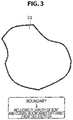
- FIGS. 2 and 3 are each an explanatory diagram for describing single lenses that the diffuser plate according to the present embodiment has.
- FIGS. 4 to 5B are each an electron micrograph of an example of a single lens group that the diffuser plate according to the present embodiment includes as seen from above.
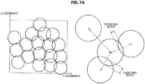
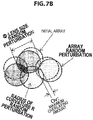
- FIGS. 6A to 7B are each an explanatory diagram for describing a locating method of the single lens group that the diffuser plate according to the present embodiment includes.
- FIGS. 8A to 9B are each an electron micrograph of an example of the single lens group that the diffuser plate according to the present embodiment includes as seen from above.
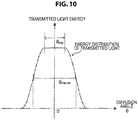
- FIG. 10 is an explanatory diagram schematically illustrating energy distribution of light having transmitted through the diffuser plate according to the present embodiment.
- FIG. 11 is an explanatory diagram for describing energy distribution of light having transmitted through the diffuser plate according to the present embodiment.
- FIG. 12 is an explanatory diagram illustrating an example of geometrical-optical diffusion properties of the diffuser plate according to the present embodiment.
- the diffuser plate 1 is a microlens array diffuser plate including a plurality of microlens (hereinafter, also referred to as "single lens") located on a base material.
- a diffuser plate 1 includes, as schematically illustrated in FIG. 1 , a transparent base material 10 and a single lens group 20 formed on a surface of the transparent base material 10.
- the transparent base material 10 is a base material made of material that can be assumed as transparent in a wavelength band of light that enters into the diffuser plate 1 according to the present embodiment.
- a transparent base material 10 may be a film-like material or may be a plate-like material.
- the material of such a base material is not particularly limited, and it is also possible to use publicly-known resin such as polymenthyl methacrylate (PMMA), polyethylene terephthalate (PET), polycarbonate (PC), or cyclo olefin copolymer (COC), for example, as the transparent base material 10, and it is also possible to use publicly-known optical glass such as quartz glass, borosilicate glass, or white glass plate.
- PMMA polymenthyl methacrylate
- PET polyethylene terephthalate
- PC polycarbonate
- COC cyclo olefin copolymer
- the shape of the transparent base material 10 is not limited to a rectangle, but may have an arbitrary shape, depending on the shape of a display device, a projection device, a lighting device, or the like in which the diffuser plate 1 is provided, for example.
- the single lens group 20 composed of a plurality of single lenses 21 is formed on the surface of the transparent base material 10.
- the single lens group 20 is preferably formed in such a manner that a plurality of single lenses 21 are adjacent to each other (in other words, in such a manner that a gap (flat portion) does not exist between the single lenses 21) as schematically illustrated in FIG. 1 .
- a component of incoming light that transmits through the diffuser plate surface as it is without scattering on the diffuser plate surface (hereinafter, also referred to as "0th order transmitted light component") can be reduced, by locating the single lenses 21 on the transparent base material 10 without a gap (in other words, locating the single lenses 21 in such a manner that the filling rate of the single lenses is 100%).
- the single lens group 20 including a plurality of single lenses 21 located adjacent to each other can further improve diffusion capability.
- each single lens 21 is not located regularly, but is located irregularly (at random), as schematically illustrated in FIG. 1 .
- irregular means regularity relevant to the location of the single lens 21 does not exist practically, in an arbitrary region of the single lens group 20 in the diffuser plate 1.
- the arbitrary region having no regularity in the location of the single lens 21 as a whole is assumed to be included in "irregular". Note that an irregular locating method of the single lens 21 in the single lens group 20 according to the present embodiment will be described again in detail below.
- the single lens 21 constituting the single lens group 20 is a convex lens.
- the surface shape of each single lens 21 is not particularly limited, and may only include a spherical component, or may include an aspherical component.
- the single lens group 20 has variations not only in the locations of the respective single lenses 21 as described above, but also in the aperture sizes and radii of curvatures of the respective single lenses 21 in the single lens group 20 as a whole.
- outer shapes of the respective single lenses 21 are not identical shapes to one another, but have various shapes as schematically illustrated in FIG. 1 , and many single lenses 21 do not have symmetry.
- the boundary between the adjacent single lenses is not structured by a straight line alone, but at least partly includes a curve.
- the outer shapes of the single lenses 21 include a plurality of bent and curved boundaries different from one another. With curves included at least partly in the boundaries between the single lenses, regularity in the location at the boundaries between the single lenses is further broken, and it is possible to further reduce a refraction component.
- FIG. 4 is a scanning electron microscope (SEM) picture in a case where part of the single lens group 20 in the diffuser plate according to the present embodiment is monitored from above by an SEM.
- SEM scanning electron microscope
- the single lens group 20 in which a plurality of single lenses 21 having characteristics as described above are located can be achieved mainly by the following two locating methods.
- the first array method is a scheme of once setting a state (hereinafter also referred to as "initial array state") serving as a reference in which the single lenses 21 having a shape serving as a reference are located regularly, and then varying (perturbing) the shapes (that is, the aperture sizes and radii of curvatures) of the single lenses 21 and the locating positions (in more detail, the vertex positions of the single lenses 21) from such an initial locating state.
- this locating method will also be referred to as “reference locating method.”
- this locating method upon experiencing a regular array of the single lenses 21, randomness is provided for the shapes and locations of the single lenses 21. Therefore, as is apparent from an SEM picture illustrated in FIG. 5A illustrating an actual appearance of locating the single lens group 20, such a location that an initial array state can be estimated to some degree when overviewing the single lens group 20 macroscopically to some degree is achieved.
- the second locating method is a locating method of locating the single lenses 21 having a shape serving as a reference at random from the beginning.
- this locating method will also be referred to as "random locating method.”
- the single lenses 21 having a shape serving as a reference are located at random, and then the shapes (that is, the aperture sizes and radii of curvatures) of the single lenses 21 are varied (perturbed). Therefore, as is apparent from an SEM picture illustrated in FIG. 5B illustrating an actual appearance of locating the single lens group 20, regularity cannot be found in the locations of the single lenses 21 even in a case of overviewing the single lens group 20 macroscopically to some degree.
- an initial array state serving as a reference is set first.
- a regular array state of the single lenses 21 is not particularly limited, but a rectangular location in which the vertex positions of the single lenses 21 are located in a square manner, a hexagonal location in which the vertex positions of the single lenses 21 are located at positions corresponding to the vertices of a hexagon and the center of the hexagon, or the like may be utilized as appropriate.
- the regular array state be a close packed array state such as a hexagonal close packed lattice.
- the lattice spacing (a reference lattice pitch G in FIG. 6B ) is used as a parameter. Then, as illustrated in the diagram at the bottom on the left side in FIG. 6A , the lattice spacing which is a parameter is reduced from a value corresponding to a close packed pattern. Accordingly, as illustrated in the diagram at the top on the right side in FIG. 6A , the respective single lenses overlie one another, so that there is no flat portion.
- each single lens 21 is moved at random from a lattice point. Specifically, using the maximum moved distance from a lattice point as a parameter (a maximum perturbation amount M in FIG. 6B ), and using the product of a random number of 0 to 1 and the maximum moved distance as a moved distance, a decision is made individually. In addition, a moved angle is also decided using a random number. Accordingly, as illustrated in the diagram at the bottom on the right side in FIG 6A , the final locating pattern of the single lenses 21 is decided.
- the x coordinate and y coordinate of the lens locating position are decided by random numbers.
- the distance from each single lens 21 already located is calculated, and if the overlying width with the single lenses 21 already located falls within a previously set acceptable range, the single lens 21 of interest shall be located. Conversely, in a case where the calculated overlying width exceeds the acceptable range, the single lens 21 of interest shall not be located. In this manner, the initial array in the random locating method is decided.
- the acceptable range in the locating method as described above is a maximum overlaying amount O v illustrated in FIG. 7B . It is possible to regard this maximum overlaying amount O v as the maximum value of the overlying width between the single lenses 21 adjacent to each other.
- the locating method of the single lenses 21 according to the present embodiment has been specifically described above with reference to FIGS. 6A to 7B .
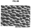
- FIGS. 8A and 8B are results of monitoring by SEM an appearance of the single lens group 20 in a case of locating the single lenses 21 in the above manner.
- FIG. 8A is an SEM picture in a case of looking at the single lens group 20 from above
- FIG. 8B is an SEM picture in a case of looking down the single lens group 20 in a diagonal direction.
- the single lens group 20 illustrated in FIGS. 8A and 8B is an example in a case of assuming that the aperture size (the aperture size before perturbation) ⁇ serving as a reference is 30 ⁇ m and the radius of curvature (the radius of curvature before perturbation) R serving as a reference is 20 ⁇ m.
- the respective single lenses 21 have various outer shapes and have been located at random.
- the respective single lenses 21 vary in lens height variously, and the boundaries between the single lenses 21 adjacent to each other present curved surfaces.
- the single lenses 21 are extremely uniform in vertex height (lens height), and it will be difficult to achieve even diffusion angle distribution properties, which is not preferable.
- the proportion of a flat portion (for example, the proportion of an area where a flat portion exists to the area of the transparent base material 10) be less than 10%.
- the proportion of a flat portion is more than or equal to 10%, the 0th order transmitted light component will be increased, and diffusion angle distribution properties may be degraded, which is not preferable.
- anisotropy may be provided for the location properties of the single lens group 20 as described above.
- top hat type diffusion as schematically illustrated in FIG. 10 is achieved in which homogeneity of energy distribution is very high within an angular component in a certain region, and energy is abruptly reduced when the certain region of this angular component is exceeded.
- the diffuser plate 1 by forming the single lens group 20 as described above on the transparent base material 10, it is possible to achieve top hat type diffusion in which the diffusion angle is ⁇ 35° in a case where it is assumed that the reference aperture size ⁇ is 30 ⁇ m and the reference radius of curvature R is 20 ⁇ m.
- Such distribution properties indicate that light entered into the diffuser plate 1 at a spot diffuses to a range of 144 mm at a position 100 mm away from the diffuser plate 1.
- the diffuser plate 1 according to the present embodiment has been described above in detail with reference to FIGS. 1 to 12 .
- the diffuser plate 1 according to the present embodiment as described above can achieve more even diffusion angle distribution properties by providing randomness for the locations of the single lenses 21 and the shapes (the aperture sizes and radii of curvatures) of the single lenses 21.
- the diffuser plate 1 according to the present embodiment by controlling the aperture sizes and radii of curvatures of the single lenses 21, it is possible to freely design the diffusion angle of light having transmitted through the diffuser plate 1.
- FIG. 13 is a flowchart illustrating an example of a flow of the manufacturing method of the diffuser plate according to the present embodiment.
- a base may be a roll-like base such as a glass roll, or may be a planar base such as a glass wafer.
- a resist (such as resist in which a metal oxide is used, for example) is formed on the base after cleaning (step S103). Processing of forming such a resist is achieved by application processing or dipping for a roll-like base, and achieved by various kinds of coating processing for a planar base.
- step S105 exposure processing is carried out on the base on which the resist has been formed.
- a publicly-known exposure method such as exposure through use of a gray scale mask or multi-exposure performed by overlaying a plurality of gray scale masks.
- a master original such as a glass master or a metal master, for example
- a soft mold is manufactured using the completed master original (step S111).
- step S113 by carrying out imprinting processing on a substrate glass, a substrate film, or the like utilizing the manufactured soft mold (step S113), the diffuser plate 1 according to the present embodiment is manufactured.
- the flow of the manufacturing method illustrated in FIG. 13 is merely an example, and the manufacturing method of the diffuser plate according to the present embodiment is not limited to the example illustrated in FIG 13 .
- FIG. 14 is an explanatory diagram schematically illustrating an example of an application example of the diffuser plate according to the present embodiment.
- the diffuser plate 1 according to the present embodiment described above is provided as appropriate in a device that needs to diffuse the light to provide its function.
- the device that needs to diffuse the light to provide the function is a display device such as various types of displays, a projection device such as a projector, and the like, for example.
- the diffuser plate 1 according to the present embodiment is also applicable to a backlight of a liquid crystal display device as illustrated at the top of FIG. 14 , and can also be used for optical shaping application as illustrated at the middle of FIG. 14 . Further, as illustrated at the bottom of FIG. 14 , the diffuser plate 1 according to the present embodiment can also be applied to various lighting devices.
- the device that needs to diffuse the light to provide the function is not limited to the above examples, and the diffuser plate 1 according to the present embodiment can be applied to other publicly known devices, as long as it is a device that utilizes diffusion of light.
- the diffuser plate according to the present invention will be described specifically, with Examples and Comparative Examples. Note that the Examples described below are just an example of the diffuser plate according to the present invention, and the diffuser plate according to the present invention is not limited to the following examples.
- Examples 1 to 3 a hexagonal close packed lattice was used as a reference location, and the shape (the aperture size ⁇ , the radius of curvature R, each perturbation amount) and a location spacing G of single lenses, and the maximum perturbation amount M were set at the respective conditions as in Table 1 below.
- FIGS. 15 and 16 illustrate simulation results of the diffuser plate shown in Example 1. As is also apparent particularly from energy distribution properties illustrated in FIG. 16 , it is seen that top hat type distribution properties have been achieved.
- Comparative Example 1 and Comparative Example 2 it has been clarified that the diffusion distribution has a non-top hat shape of discrete diffraction, so that desired optical properties are not obtained.
- the random location was used as the reference location, and the shapes (the aperture size ⁇ , radius of curvature R, each perturbation amount) and locations (E x , O v ) of single lenses were set at the respective conditions as in Table 2 below.
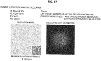
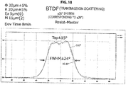
- FIGS. 17 and 18 illustrate simulation results of the diffuser plate shown in Example 4. As is also apparent particularly from energy distribution properties illustrated in FIG. 18 , it is seen that top hat type distribution properties have been achieved.
- Comparative Example 3 it has been clarified that the diffusion distribution has a non-top hat shape of discrete diffraction, so that desired optical properties are not obtained.
Landscapes
- Physics & Mathematics (AREA)
- General Physics & Mathematics (AREA)
- Optics & Photonics (AREA)
- Engineering & Computer Science (AREA)
- General Engineering & Computer Science (AREA)
- Optical Elements Other Than Lenses (AREA)
- Planar Illumination Modules (AREA)
- Devices For Indicating Variable Information By Combining Individual Elements (AREA)
- Liquid Crystal (AREA)
- Projection Apparatus (AREA)
Abstract
Description
- The present invention relates to a diffuser plate, a display device, a projection device, and a lighting device.
- A diffuser plate that scatters incoming light to various directions is widely utilized in various devices, for example, a display device such as a display, a projection device such as a projector, and various types of lighting devices. An incoming light diffusing mechanism in this diffuser plate is roughly classified into a mechanism that utilizes light refraction resulting from the surface shape of the diffuser plate and a mechanism that utilizes scattering by a substance existing inside a bulk body and having different refractive index from the circumference. One of the diffuser plates which utilize the light refraction resulting from the surface shape is what is called a microlens array diffuser plate including a plurality of microlenses having sizes of approximately several tens of micrometers and located on the surface of the bulk body.
- As such a microlens array diffuser plate,
Patent Literature 1 below discloses a diffuser plate for a reticle, and such a diffuser plate is designed to have variations in pitches and heights of microlenses. Specifically,Patent Literature 1 below discloses that a microlens pitch P is set at 8 µm ≤ P ≤ 30 µm and setting a microlens height H is set at 0.01×P ≤ H ≤ 0.1×P. - In addition, as the microlens array diffuser plate,
Patent Literature 2 below discloses that, by setting a diameter (D) of microlenses constituting a microlens array at more than or equal to 100 µm and less than or equal to 1000 µm and setting a surface roughness (Ra) of the microlenses at more than or equal to 0.1 µm and less than or equal to 10 µm, a light diffusion effect is imparted to the lens surface. In thisPatent Literature 2, an arrangement pattern of the microlenses is a random arrangement pattern similarly toPatent Literature 1 above, but introduction of randomness for the microlens height is denied stating that stress concentration can be reduced by keeping the microlens height constant. -
- Patent Literature 1:
-
JP H3-192232A - Patent Literature 2:
-
JP 2004-145330A - However,
Patent Literature 1 above fails to mention the radius of curvature of each microlens, and has a problem in that it is difficult to achieve more even (flat) diffusion angle distribution properties. In addition, even if the technology disclosed inPatent Literature 2 above is used, it is difficult to achieve more even (flat) diffusion angle distribution properties. - Thus, the present invention was made in view of the above-described problems, and the present invention has an object to provide a diffuser plate, a display device, a projection device, and a lighting device that can achieve more even diffusion angle distribution properties.
- In order to solve the above problem, according to an aspect of the present invention, there is provided a diffuser plate of a microlens array type, the diffuser plate including: a single lens group located on a surface of a transparent base material, in which aperture sizes and radii of curvatures of respective single lenses constituting the single lens group vary in the single lens group as a whole, and vertex positions of the respective single lenses are located irregularly, and energy distribution of light that transmits through the single lens group is substantially even in a predetermined diffusion angle range.
- It is preferable that boundaries include curves different from one another, each of the boundaries being formed between one of the single lenses and an adjacent one of the single lenses.
- It is preferable that Expression (1) below be satisfied, where a reference aperture size of the single lens group is represented by ϕ, and a perturbation width which is a degree of variations in aperture sizes in the single lens group is represented by Δϕ.
[Math. 1]
- It is preferable that Expression (2) below be satisfied, where a reference radius of curvature of the single lens group is represented by R, and a perturbation width which is a degree of variations in radii of curvatures in the single lens group is represented by ΔR.
[Math. 2]
- It is preferable that Expression (3) below be satisfied, where that a maximum elevation difference in the vertex positions between the single lenses constituting the single lens group is represented by ΔZmax, and a maximum vertex height in the single lens group is represented by Z.
[Math. 3]
- It is preferable that Expression (4) below be satisfied, where, in energy distribution of light that transmits through the single lens group, a diffusion angle range in which the energy distribution becomes substantially even is represented by θtop, and a full width at half maximum of the energy distribution is represented by θFWHM,
[Math. 4]
- The vertex positions of the respective single lenses constituting the single lens group may be located irregularly using positions of vertices of the respective single lenses when assuming that the single lenses are arranged regularly as a reference, such that a moved amount from the reference falls within a predetermined range. In this case, it is preferable that Expression (5) below be satisfied, where the moved amount at maximum in the single lens group is represented by M, a reference aperture size of the single lens group is represented byϕ, and a reference radius of curvature of the single lens group is represented by R.
[Math. 5]
- Further, it is preferable that Δr/ϕ ≠ 0 be satisfied, where the moved amount from the reference in the single lens group is represented by Δr, and a reference aperture size of the single lens group is represented by ϕ.
- The respective single lenses constituting the single lens group may be located irregularly on the transparent base material. In this case, it is preferable that Expression (6) below be satisfied, where a maximum value of an overlying width between the single lenses adjacent to each other in the single lens group is represented by Ov, a reference aperture size of the single lens group is represented by ϕ, and a reference radius of curvature of the single lens group is represented by R.
[Math. 6]
- The transparent base material may be any of a resin substrate, a resin film, and a glass substrate.
- Further, in order to solve the above problem, according to another aspect of the present invention, there is provided a display device including the diffuser plate.
- Further, in order to solve the above problem, according to another aspect of the present invention, there is provided a projection device including the diffuser plate.
- Further, in order to solve the above problem, according to another aspect of the present invention, there is provided a lighting device including the diffuser plate.
- According to the present invention as described above, it is possible to achieve more even diffusion angle distribution properties.
-
- [
FIG. 1] FIG. 1 is an explanatory diagram schematically illustrating a structure of a diffuser plate according to an embodiment of the present invention. - [
FIG. 2] FIG. 2 is an explanatory diagram for describing single lenses that the diffuser plate according to the embodiment has. - [
FIG. 3] FIG. 3 is an explanatory diagram for describing single lenses that the diffuser plate according to the embodiment has. - [
FIG. 4] FIG. 4 is an electron micrograph of an example of a single lens group that the diffuser plate according to the embodiment includes as seen from above. - [
FIG. 5A] FIG. 5A is an electron micrograph of an example of a single lens group that the diffuser plate according to the embodiment includes as seen from above. - [
FIG. 5B] FIG. 5B is an electron micrograph of an example of a single lens group that the diffuser plate according to the embodiment includes as seen from above. - [
FIG. 6A] FIG. 6A is an explanatory diagram for describing a locating method of the single lens group that the diffuser plate according to the embodiment includes. - [
FIG. 6B] FIG. 6B is an explanatory diagram for describing a locating method of the single lens group that the diffuser plate according to the embodiment includes. - [
FIG. 7A] FIG. 7A is an explanatory diagram for describing a locating method of the single lens group that the diffuser plate according to the embodiment includes. - [
FIG. 7B] FIG. 7B is an explanatory diagram for describing a locating method of the single lens group that the diffuser plate according to the embodiment includes. - [
FIG. 8A] FIG. 8A is an electron micrograph of an example of the single lens group that the diffuser plate according to the embodiment includes as seen from above. - [
FIG 8B] FIG. 8B is an electron micrograph of an example of the single lens group that the diffuser plate according to the embodiment includes as seen from above. - [
FIG. 9A] FIG. 9A is an electron micrograph of an example of the single lens group that the diffuser plate according to the embodiment includes as seen from above. - [
FIG. 9B] FIG. 9B is an electron micrograph of an example of the single lens group that the diffuser plate according to the embodiment includes as seen from above. - [
FIG. 10] FIG. 10 is an explanatory diagram schematically illustrating an energy distribution of light having transmitted through the diffuser plate according to the embodiment. - [
FIG. 11] FIG. 11 is an explanatory diagram for describing an energy distribution of light having transmitted through the diffuser plate according to the embodiment. - [
FIG. 12] FIG. 12 is an explanatory diagram illustrating an example of geometrical-optical diffusion properties of the diffuser plate according to the embodiment. - [
FIG. 13] FIG. 13 is a flowchart illustrating an example of a flow of a manufacturing method of the diffuser plate according to the embodiment. - [
FIG. 14] FIG. 14 is an explanatory diagram schematically illustrating an example of an application example of the diffuser plate according to the embodiment. - [
FIG. 15] FIG. 15 is an explanatory diagram for describing results of Example 1. - [
FIG. 16] FIG. 16 is an explanatory diagram for describing results of Example 1. - [
FIG. 17] FIG. 17 is an explanatory diagram for describing results of Example 4. - [
FIG. 18] FIG 18 is an explanatory diagram for describing results of Example 4. - Hereinafter, (a) preferred embodiment(s) of the present invention will be described in detail with reference to the appended drawings. Note that, in this specification and the appended drawings, structural elements that have substantially the same function and structure are denoted with the same reference numerals, and repeated explanation of these structural elements is omitted.
- Prior to describing a diffuser plate according to an embodiment of the present invention in detail, an overview of the diffuser plate according to an embodiment of the present invention will be mentioned below briefly.
- The diffuser plate according to an embodiment of the present invention as will be described below in detail is a microlens array diffuser plate having light homogeneous diffusion and optical aperture homogeneous expanding functions. Optical bodies (that is, microlenses) that this diffuser plate has are structures characterized in that the optical bodies are different in shape of convex surfaces or concave surfaces each having the light diffusion function from one another, and that a boundary contour of each lens is in contact with an adjacent lens with a different curve.
- In a case of optical bodies with a conventional microlens array structure as disclosed in
Patent Literature 1 andPatent Literature 2 above, a general Gaussian light diffusion function and a moire reducing function in imaging equipment may only be added, and there is a problem in that it is difficult to satisfy distribution properties of homogeneous energy distribution. That is, with respect to collimated light in a visible light region and telecentric light having a principal ray with a collimating property and having a certain aperture, there is a problem in that an issue concerning an optical function (hereinafter also referred to as "top hat type diffusion") that homogeneity of energy distribution is very high within an angular component in a certain region, and if the certain region of this angular component is exceeded, energy may be reduced abruptly cannot be resolved. - By providing perturbation (in other words, variations) for the locations, radii of curvatures, and circular aperture sizes of respective unit cells constituting the microlens array, the diffuser plate according to an embodiment of the present invention as will be described below in detail has optical bodies including many bents and curved surfaces that have a plurality of bent and curved surface regions different from one another, in which the boundaries of the regions are curved surfaces different from one another, and an overview projection trajectory in which tangent orientations are different from one another are sectioned with different curves. Accordingly, it is possible to resolve the issue as described above and to achieve optical bodies having a high homogeneous diffusion function.
- Characteristics of the diffuser plate as will be described below in detail are summarized as follows:
- 1) A curved surface portion of each microlens is a spherical body or an aspherical body.
- 2) The locations of microlenses constituting the microlens array can be locations perturbed at random from a periodic array. In this case, ΔP/P ≠ 0 is satisfied, where a lattice position to serve as a reference is represented by P and a perturbation width (variation width) is represented by ΔP.
- 3) In the above 2) case, a reference array (lattice to serve as a reference) can be a hexagonal lattice, for example. In this case, a perturbation ratio (M/2)×2/(ϕ2+R2)0.5 is more than or equal to 0.12, where a reference aperture size and a reference radius of curvature of a microlens in the reference array are represented by ϕ and R, respectively, and the maximum perturbation amount is represented by M/2.
- 4) In the microlens array, the ratio |Δϕ/ϕ| of the perturbation width Δϕ to the reference aperture size ϕ is more than or equal to 5% and less than or equal to 25%.
- 5) In the microlens array, the ratio |ΔR/R| of the perturbation width ΔR to the reference radius of curvature R is more than or equal to 5% and less than or equal to 70%.
- 6) The locations of microlenses constituting the microlens array can be a random array, not using a periodic array as a reference as in the above 2). In such a random array case, a perturbation ratio Ov/(ϕ2+R2)0.5 is more than or equal to 0.12, where the reference aperture size of the microlens is ϕ, the reference radius of curvature is represented by R, and the maximum overlapping amount (the maximum value of the overlying width) between the microlenses is represented by Ov.
- 7) In the microlens array, the ratio ΔZmax/Z is more than or equal to 0.015, where the maximum elevation difference between vertices of the respective microlenses constituting the array is represented by ΔZmax, and the maximum vertex height is represented by Z.
- 8) The respective boundaries between microlenses constituting the microlens array and adjacent microlenses have bent shapes different from one another.
- 9) A flat portion of an optical body (diffuser plate) on which microlenses are located is less than 10%.
- Hereinafter, the diffuser plate according to an embodiment of the present invention having characteristics as described above will be described in detail.
- Hereinafter, with reference to
FIGS. 1 to 12 , adiffuser plate 1 according to a first embodiment of the present invention will be described in detail. -
FIG. 1 is an explanatory diagram schematically illustrating a structure of the diffuser plate according to the present embodiment.FIGS. 2 and3 are each an explanatory diagram for describing single lenses that the diffuser plate according to the present embodiment has.FIGS. 4 to 5B are each an electron micrograph of an example of a single lens group that the diffuser plate according to the present embodiment includes as seen from above.FIGS. 6A to 7B are each an explanatory diagram for describing a locating method of the single lens group that the diffuser plate according to the present embodiment includes.FIGS. 8A to 9B are each an electron micrograph of an example of the single lens group that the diffuser plate according to the present embodiment includes as seen from above.FIG. 10 is an explanatory diagram schematically illustrating energy distribution of light having transmitted through the diffuser plate according to the present embodiment.FIG. 11 is an explanatory diagram for describing energy distribution of light having transmitted through the diffuser plate according to the present embodiment.FIG. 12 is an explanatory diagram illustrating an example of geometrical-optical diffusion properties of the diffuser plate according to the present embodiment. - The
diffuser plate 1 according to the present embodiment is a microlens array diffuser plate including a plurality of microlens (hereinafter, also referred to as "single lens") located on a base material. Such adiffuser plate 1 includes, as schematically illustrated inFIG. 1 , atransparent base material 10 and asingle lens group 20 formed on a surface of thetransparent base material 10. - The
transparent base material 10 is a base material made of material that can be assumed as transparent in a wavelength band of light that enters into thediffuser plate 1 according to the present embodiment. Such atransparent base material 10 may be a film-like material or may be a plate-like material. The material of such a base material is not particularly limited, and it is also possible to use publicly-known resin such as polymenthyl methacrylate (PMMA), polyethylene terephthalate (PET), polycarbonate (PC), or cyclo olefin copolymer (COC), for example, as thetransparent base material 10, and it is also possible to use publicly-known optical glass such as quartz glass, borosilicate glass, or white glass plate. AlthoughFIG. 1 illustrates an example in which thetransparent base material 10 is rectangular, the shape of thetransparent base material 10 is not limited to a rectangle, but may have an arbitrary shape, depending on the shape of a display device, a projection device, a lighting device, or the like in which thediffuser plate 1 is provided, for example. - The
single lens group 20 composed of a plurality ofsingle lenses 21 is formed on the surface of thetransparent base material 10. In thediffuser plate 1 according to the present embodiment, thesingle lens group 20 is preferably formed in such a manner that a plurality ofsingle lenses 21 are adjacent to each other (in other words, in such a manner that a gap (flat portion) does not exist between the single lenses 21) as schematically illustrated inFIG. 1 . A component of incoming light that transmits through the diffuser plate surface as it is without scattering on the diffuser plate surface (hereinafter, also referred to as "0th order transmitted light component") can be reduced, by locating thesingle lenses 21 on thetransparent base material 10 without a gap (in other words, locating thesingle lenses 21 in such a manner that the filling rate of the single lenses is 100%). As a result, thesingle lens group 20 including a plurality ofsingle lenses 21 located adjacent to each other can further improve diffusion capability. - Also, in the
single lens group 20 according to the present embodiment, eachsingle lens 21 is not located regularly, but is located irregularly (at random), as schematically illustrated inFIG. 1 . Here, "irregular" means regularity relevant to the location of thesingle lens 21 does not exist practically, in an arbitrary region of thesingle lens group 20 in thediffuser plate 1. Thus, even if a certain kind of regularity exists in the location of thesingle lens 21 at a microscopic region in an arbitrary region, the arbitrary region having no regularity in the location of thesingle lens 21 as a whole is assumed to be included in "irregular". Note that an irregular locating method of thesingle lens 21 in thesingle lens group 20 according to the present embodiment will be described again in detail below. - In the present embodiment, the
single lens 21 constituting thesingle lens group 20 is a convex lens. In addition, in thesingle lens group 20 according to the present embodiment, the surface shape of eachsingle lens 21 is not particularly limited, and may only include a spherical component, or may include an aspherical component. - In addition, the
single lens group 20 according to the present embodiment has variations not only in the locations of the respectivesingle lenses 21 as described above, but also in the aperture sizes and radii of curvatures of the respectivesingle lenses 21 in thesingle lens group 20 as a whole. - By providing a plurality of
single lenses 21 so as to be adjacent to one another, forming thesingle lenses 21 irregularly on thetransparent base material 10, and providing variations (randomness) in the aperture sizes and radii of curvatures of the respectivesingle lenses 21, outer shapes of the respectivesingle lenses 21 are not identical shapes to one another, but have various shapes as schematically illustrated inFIG. 1 , and manysingle lenses 21 do not have symmetry. - In such a case, as schematically illustrated in
FIG. 2 , many situations occur in which a single lens A has a radius of curvature rA, whereas a single lens B has a radius of curvature rB (# rA). In a case where adjacent single lenses are different in radius of curvature, the boundary between the adjacent single lenses is not structured by a straight line alone, but at least partly includes a curve. As a result, as schematically illustrated inFIG. 3 , the outer shapes of the single lenses 21 (a projection trajectory of outer shapes in a case of overviewing the single lenses 21) include a plurality of bent and curved boundaries different from one another. With curves included at least partly in the boundaries between the single lenses, regularity in the location at the boundaries between the single lenses is further broken, and it is possible to further reduce a refraction component. -
FIG. 4 is a scanning electron microscope (SEM) picture in a case where part of thesingle lens group 20 in the diffuser plate according to the present embodiment is monitored from above by an SEM. As is apparent fromFIG. 4 , it is seen that the outer shapes (an overview projection trajectory) of thesingle lenses 21 constituting thesingle lens group 20 have various shapes, and that thesingle lenses 21 are also different in aperture size from one another. - Hereinafter, a locating method of the
single lenses 21 as described above will be specifically described. - In the
diffuser plate 1 according to the present embodiment, thesingle lens group 20 in which a plurality ofsingle lenses 21 having characteristics as described above are located can be achieved mainly by the following two locating methods. - The first array method is a scheme of once setting a state (hereinafter also referred to as "initial array state") serving as a reference in which the
single lenses 21 having a shape serving as a reference are located regularly, and then varying (perturbing) the shapes (that is, the aperture sizes and radii of curvatures) of thesingle lenses 21 and the locating positions (in more detail, the vertex positions of the single lenses 21) from such an initial locating state. Hereinafter, this locating method will also be referred to as "reference locating method." In this locating method, upon experiencing a regular array of thesingle lenses 21, randomness is provided for the shapes and locations of thesingle lenses 21. Therefore, as is apparent from an SEM picture illustrated inFIG. 5A illustrating an actual appearance of locating thesingle lens group 20, such a location that an initial array state can be estimated to some degree when overviewing thesingle lens group 20 macroscopically to some degree is achieved. - The second locating method is a locating method of locating the
single lenses 21 having a shape serving as a reference at random from the beginning. Hereinafter, this locating method will also be referred to as "random locating method." In this locating method, thesingle lenses 21 having a shape serving as a reference are located at random, and then the shapes (that is, the aperture sizes and radii of curvatures) of thesingle lenses 21 are varied (perturbed). Therefore, as is apparent from an SEM picture illustrated inFIG. 5B illustrating an actual appearance of locating thesingle lens group 20, regularity cannot be found in the locations of thesingle lenses 21 even in a case of overviewing thesingle lens group 20 macroscopically to some degree. - Hereinafter, with reference to
FIGS. 6A and6B , a flow of the reference locating method will be briefly described. - As illustrated in
FIG. 6A , in the reference locating method, first, an initial array state serving as a reference is set first. A regular array state of thesingle lenses 21 is not particularly limited, but a rectangular location in which the vertex positions of thesingle lenses 21 are located in a square manner, a hexagonal location in which the vertex positions of thesingle lenses 21 are located at positions corresponding to the vertices of a hexagon and the center of the hexagon, or the like may be utilized as appropriate. On this occasion, in order to minimize occurrence of a flat portion in thesingle lens group 20 after carrying out the reference locating method, it is preferable that the regular array state be a close packed array state such as a hexagonal close packed lattice. - In such a reference locating method, as illustrated in the diagram at the middle on the left side in
FIG. 6A , the lattice spacing (a reference lattice pitch G inFIG. 6B ) is used as a parameter. Then, as illustrated in the diagram at the bottom on the left side inFIG. 6A , the lattice spacing which is a parameter is reduced from a value corresponding to a close packed pattern. Accordingly, as illustrated in the diagram at the top on the right side inFIG. 6A , the respective single lenses overlie one another, so that there is no flat portion. - Thereafter, as illustrated in the diagram at the middle on the right side in
FIG. 6A , the lens center (vertex position) of eachsingle lens 21 is moved at random from a lattice point. Specifically, using the maximum moved distance from a lattice point as a parameter (a maximum perturbation amount M inFIG. 6B ), and using the product of a random number of 0 to 1 and the maximum moved distance as a moved distance, a decision is made individually. In addition, a moved angle is also decided using a random number. Accordingly, as illustrated in the diagram at the bottom on the right side inFIG 6A , the final locating pattern of thesingle lenses 21 is decided. - Thereafter, by further performing perturbation using the aperture size ϕ and the radius of curvature R of the
single lenses 21 as illustrated inFIG. 6B as parameters, it is possible to locate at random thesingle lenses 21 having random shapes. - In the reference locating method as described above, it is preferable that Expression (101) below be satisfied, where the maximum moved amount (the maximum perturbation amount in
FIG. 6B ) in thesingle lens group 20 is represented by M, the reference aperture size of thesingle lens group 20 is represented by ϕ, and the reference radius of curvature of thesingle lens group 20 is represented by R. In addition, it is preferable that Δr/ϕ ≠ 0 be satisfied, where, a moved amount from the initial array in thesingle lens group 20 is represented by Δr, and the reference aperture size of thesingle lens group 20 is represented by ϕ.
[Math. 7]
- In a case where a perturbation ratio expressed by the left side of Expression (101) above is less than 0.12, the degree of variations in parameters for achieving a random location will be insufficient, and it will be difficult to achieve sufficient randomness. In addition, that Δr/ϕ ≠ 0 is satisfied means displacing the vertex positions of all the
single lenses 21 from regular vertex positions. In this manner, it is possible to introduce irregularity more reliably for the locations of thesingle lenses 21 in thesingle lens group 20. - Next, with reference to
FIGS. 7A and7B , a flow of the random locating method will be briefly described. - In the random locating method, as illustrated in
FIG. 7A , in a case of considering the lens locating position in the xy coordinate system, the x coordinate and y coordinate of the lens locating position are decided by random numbers. On this occasion, for asingle lens 21 of interest, the distance from eachsingle lens 21 already located is calculated, and if the overlying width with thesingle lenses 21 already located falls within a previously set acceptable range, thesingle lens 21 of interest shall be located. Conversely, in a case where the calculated overlying width exceeds the acceptable range, thesingle lens 21 of interest shall not be located. In this manner, the initial array in the random locating method is decided. - The acceptable range in the locating method as described above is a maximum overlaying amount Ov illustrated in
FIG. 7B . It is possible to regard this maximum overlaying amount Ov as the maximum value of the overlying width between thesingle lenses 21 adjacent to each other. - The foregoing is an overview of the random locating method, and a more specific algorithm for the random locating method is not particularly limited, but it is possible to utilize a publicly-known method as disclosed in
JP 2012-181816A - After deciding the initial array in the above manner, by further performing perturbation using the aperture size ϕ and the radius of curvature R of the
single lenses 21 as illustrated inFIG. 7B as parameters, it is possible to locate at random thesingle lenses 21 having random shapes, and it is possible to suppress occurrence of a flat portion. - In the random locating method as described above, it is preferable that Expression (103) below be satisfied, where the maximum value of the overlying width between single lenses adjacent to each other in the
single lens group 20 is represented by Ov, the reference aperture size of thesingle lens group 20 is represented by ϕ, and the reference radius of curvature of thesingle lens group 20 is represented by R.
[Math. 8]
- In a case where the perturbation ratio expressed by the left side of Expression (103) above is less than 0.12, the degree of variations in parameters for achieving the random location will be insufficient, and it will be difficult to achieve sufficient randomness.
- The locating method of the
single lenses 21 according to the present embodiment has been specifically described above with reference toFIGS. 6A to 7B . -
FIGS. 8A and8B are results of monitoring by SEM an appearance of thesingle lens group 20 in a case of locating thesingle lenses 21 in the above manner.FIG. 8A is an SEM picture in a case of looking at thesingle lens group 20 from above, andFIG. 8B is an SEM picture in a case of looking down thesingle lens group 20 in a diagonal direction. Thesingle lens group 20 illustrated inFIGS. 8A and8B is an example in a case of assuming that the aperture size (the aperture size before perturbation) ϕ serving as a reference is 30 µm and the radius of curvature (the radius of curvature before perturbation) R serving as a reference is 20 µm. - As is apparent from
FIG. 8A , it is seen that the respectivesingle lenses 21 have various outer shapes and have been located at random. In addition, as is apparent fromFIG. 8B , it is seen that the respectivesingle lenses 21 vary in lens height variously, and the boundaries between thesingle lenses 21 adjacent to each other present curved surfaces. Through detailed analysis of these SEM pictures, the maximum elevation difference in vertex position between thesingle lenses 21 was approximately 8 µm, and the surface roughness (Ra) at the vertex positions of thesingle lenses 21 was approximately 6 nm. - Location properties of the
single lens group 20 achieved by the locating method of thesingle lenses 21 as described above will be briefly described below. - In the
single lens group 20 achieved by the locating method as described above, it is preferable that Expression (105) be satisfied, where the reference aperture size (the aperture size before perturbation) of thesingle lens group 20 is represented by ϕ, and a perturbation width which is the degree of variations in aperture sizes in thesingle lens group 20 is represented by Δϕ.
[Math. 9]
- In a case where the ratio expressed by |Δϕ/ϕ| is less than 5%, the degree of variations in aperture sizes will be insufficient, and consequently, randomness of the locations of the
single lenses 21 will be insufficient, which is not preferable. In addition, in a case where the ratio expressed by |Δϕ/ϕ| exceeds 25%, deformations of the structure of thesingle lenses 21 themselves and the macroscopic structure of thesingle lens group 20 will be increased abruptly asFIG. 9A shows an SEM picture in a case where |Δϕ/ϕ| = 25%, which is not preferable. - In addition, in the
single lens group 20 achieved by the locating method as described above, it is preferable that Expression (107) below be satisfied, where the reference radius of curvature (the radius of curvature before perturbation) of thesingle lens group 20 is represented by R, and the perturbation width which is the degree of variations in radii of curvatures in thesingle lens group 20 is represented by ΔR.
[Math. 10]
- In a case where the ratio expressed by |ΔR/R| is less than 5%, the degree of variations in radii of curvatures will be insufficient, and consequently, randomness of the locations of the
single lenses 21 will be insufficient, which is not preferable. In addition, in a case where the ratio expressed by |ΔR/R| exceeds 70%, deformations of the structure of thesingle lenses 21 themselves and the macroscopic structure of thesingle lens group 20 will be increased abruptly asFIG. 9B shows an SEM picture in a case where |ΔR/R| = 70%, which is not preferable. - In addition, it is preferable that Expression (109) below be satisfied, where the maximum elevation difference in vertex position between the
single lenses 21 constituting thesingle lens group 20 is represented by ΔZmax, and the maximum vertex height in thesingle lens group 20 is represented by Z.
[Math. 11]
- In a case where the ratio expressed by |ΔZmax/Z| is less than 0.015, the
single lenses 21 are extremely uniform in vertex height (lens height), and it will be difficult to achieve even diffusion angle distribution properties, which is not preferable. - In addition, in the
single lens group 20 in which thesingle lenses 21 as described above are located, it is preferable that the proportion of a flat portion (for example, the proportion of an area where a flat portion exists to the area of the transparent base material 10) be less than 10%. In a case where the proportion of a flat portion is more than or equal to 10%, the 0th order transmitted light component will be increased, and diffusion angle distribution properties may be degraded, which is not preferable. - Note that, in the diffuser plate according to the present embodiment, anisotropy may be provided for the location properties of the
single lens group 20 as described above. - Next, with reference to
FIGS. 10 and11 , transmitted light energy distribution of thediffuser plate 1 having thesingle lens group 20 as described above will be specifically described. - When collimated light in a visible light region or telecentric light having a principal ray with a collimating property and having a certain aperture enters into the
diffuser plate 1 as described above, top hat type diffusion as schematically illustrated inFIG. 10 is achieved in which homogeneity of energy distribution is very high within an angular component in a certain region, and energy is abruptly reduced when the certain region of this angular component is exceeded. - Here, as illustrated in
FIG. 10 , in a case of assuming that a diffusion angle width of a region in which homogeneity of energy distribution is high is represented by θtop, and a full width at half maximum of such energy distribution is represented by θFWHM, an appearance of fluctuations in energy ratio in a case of changing the ratio θtop/θFWHM (=a) was analyzed utilizing a commercially available application for ray tracing simulation. Obtained results are illustrated inFIG. 11 . - As a result, it has been clarified that, in a case where the ratio a becomes more than or equal to 1/3, homogeneous central energy as schematically illustrated in
FIG. 10 is achieved, not Gaussian diffusion apparently. In addition, it has been clarified that, in a case where the ratio a becomes more than or equal to 1/2, the central energy in a homogeneous region becomes 20%, and diffusivity with the light collecting function is achieved. - Consequently, in the
diffuser plate 1 according to the present embodiment, it is preferable that Expression (111) below be satisfied.
[Math. 12]
- Next, with reference to
FIG 12 , geometrical-optical diffusion properties of thediffuser plate 1 having thesingle lens group 20 as described above will be specifically described. - In the
diffuser plate 1 according to the present embodiment, by forming thesingle lens group 20 as described above on thetransparent base material 10, it is possible to achieve top hat type diffusion in which the diffusion angle is ±35° in a case where it is assumed that the reference aperture size ϕ is 30 µm and the reference radius of curvature R is 20 µm. Such distribution properties indicate that light entered into thediffuser plate 1 at a spot diffuses to a range of 144 mm at a position 100 mm away from thediffuser plate 1. - The
diffuser plate 1 according to the present embodiment has been described above in detail with reference toFIGS. 1 to 12 . - The
diffuser plate 1 according to the present embodiment as described above can achieve more even diffusion angle distribution properties by providing randomness for the locations of thesingle lenses 21 and the shapes (the aperture sizes and radii of curvatures) of thesingle lenses 21. In addition, in thediffuser plate 1 according to the present embodiment, by controlling the aperture sizes and radii of curvatures of thesingle lenses 21, it is possible to freely design the diffusion angle of light having transmitted through thediffuser plate 1. - Hereinafter, with reference to
FIG. 13 , an example of a manufacturing method of thediffuser plate 1 according to the first embodiment of the present invention will be briefly described.FIG. 13 is a flowchart illustrating an example of a flow of the manufacturing method of the diffuser plate according to the present embodiment. - In the manufacturing method of the diffuser plate according to the present embodiment, cleaning of a base is carried out first (step S101). For example, such a base may be a roll-like base such as a glass roll, or may be a planar base such as a glass wafer.
- Next, a resist (such as resist in which a metal oxide is used, for example) is formed on the base after cleaning (step S103). Processing of forming such a resist is achieved by application processing or dipping for a roll-like base, and achieved by various kinds of coating processing for a planar base.
- Thereafter, exposure processing is carried out on the base on which the resist has been formed (step S105). To such exposure processing, it is possible to apply as appropriate a publicly-known exposure method such as exposure through use of a gray scale mask or multi-exposure performed by overlaying a plurality of gray scale masks.
- Thereafter, by subjecting the base after exposure to alkaline development (step S107), a master original (such as a glass master or a metal master, for example) for manufacturing the
diffuser plate 1 according to the present embodiment is completed (step S109). Thereafter, a soft mold is manufactured using the completed master original (step S111). - Next, by carrying out imprinting processing on a substrate glass, a substrate film, or the like utilizing the manufactured soft mold (step S113), the
diffuser plate 1 according to the present embodiment is manufactured. - Note that the flow of the manufacturing method illustrated in
FIG. 13 is merely an example, and the manufacturing method of the diffuser plate according to the present embodiment is not limited to the example illustrated inFIG 13 . - Next, with reference to
FIG. 14 , an application example of thediffuser plate 1 according to the present embodiment will be briefly described.FIG. 14 is an explanatory diagram schematically illustrating an example of an application example of the diffuser plate according to the present embodiment. - Note that the
diffuser plate 1 according to the present embodiment described above is provided as appropriate in a device that needs to diffuse the light to provide its function. The device that needs to diffuse the light to provide the function is a display device such as various types of displays, a projection device such as a projector, and the like, for example. - In addition, the
diffuser plate 1 according to the present embodiment is also applicable to a backlight of a liquid crystal display device as illustrated at the top ofFIG. 14 , and can also be used for optical shaping application as illustrated at the middle ofFIG. 14 . Further, as illustrated at the bottom ofFIG. 14 , thediffuser plate 1 according to the present embodiment can also be applied to various lighting devices. - Also, the device that needs to diffuse the light to provide the function is not limited to the above examples, and the
diffuser plate 1 according to the present embodiment can be applied to other publicly known devices, as long as it is a device that utilizes diffusion of light. - Next, the diffuser plate according to the present invention will be described specifically, with Examples and Comparative Examples. Note that the Examples described below are just an example of the diffuser plate according to the present invention, and the diffuser plate according to the present invention is not limited to the following examples.
- Hereinafter, utilizing a commercially available application for ray tracing simulation, various properties in cases where the
single lenses 21 were located by the reference locating method and the random locating method, respectively, were simulated. Note that, in the following simulations, a lens material that forms thesingle lenses 21 was transparent resin or glass. - In Examples 1 to 3, a hexagonal close packed lattice was used as a reference location, and the shape (the aperture size ϕ, the radius of curvature R, each perturbation amount) and a location spacing G of single lenses, and the maximum perturbation amount M were set at the respective conditions as in Table 1 below.
- In Comparative Example 1, upon setting the perturbation amounts of the aperture size ϕ and the radius of curvature R at 0, the respective conditions were set as in Table 1 below.
- In Comparative Example 2, upon setting the perturbation amounts of the aperture size ϕ and the radius of curvature R at less than 0.12, the respective conditions were set as in Table 1 below.
- Note that criteria for performance determination are as follows.
- A: The diffused light distribution has a top hat shape, and an energy change at a top part is less than or equal to 20%
- B: The diffused light distribution has a top hat shape, and an energy change at the top part exceeds 20%
- C: The diffused light distribution does not have a top hat shape (discrete diffraction)
- Obtained results are also shown in Table 1 below. In Examples 1 to 3, it is seen that the diffusion distribution has a top hat shape with different TOP widths, and desired properties have been obtained.
FIGS. 15 and16 illustrate simulation results of the diffuser plate shown in Example 1. As is also apparent particularly from energy distribution properties illustrated inFIG. 16 , it is seen that top hat type distribution properties have been achieved. - On the other hand, in Comparative Example 1 and Comparative Example 2, it has been clarified that the diffusion distribution has a non-top hat shape of discrete diffraction, so that desired optical properties are not obtained.
-
Table 1 Reference aperture size φ µm Perturbation width φ ± (%) Radius of curvature R µm R Perturbation ±(%) Hexagonal lattice spacing G µm Maximum perturbation amount M(/2) µm φ·R Perturbation ratio Elevation Difference Z Dispersion Elevation difference between adjacent vertices ΔZmax/Z TOP width degree (±) FWHM degree (±) Performance determination Example 1 45 10 40 10 28 11 0.183 9.7 2.21 0.48 0.049 12 16 A Example 2 130 10 500 10 80 80 0.155 4.8 0.97 0.12 0.025 2 4 A Example 3 150 10 300 10 103 43 0.128 11.7 6.00 0.24 0.021 4 6 B Comparative Example 1 150 0 300 0 110 40 0.119 9.1 3.70 0.20 0.022 - - C Comparative Example 2 100 10 150 10 78 19 0.105 98 3.70 0.30 0.031 - - C - In Examples 4 to 11, the random location was used as the reference location, and the shapes (the aperture size ϕ, radius of curvature R, each perturbation amount) and locations (Ex, Ov) of single lenses were set at the respective conditions as in Table 2 below.
- In Comparative Example 3, upon setting the perturbation amounts of the aperture size ϕ and the radius of curvature R at less than 0.12, the respective conditions were set as in Table 2 below.
- Here, in Examples 4 to 11 and Comparative Example 3 above, criteria for performance determination are as described above.
- Obtained results are also shown in Table 2 below. In Examples 4 to 11, it is seen that the diffusion distribution has a top hat shape with different TOP widths, and desired properties have been obtained.
FIGS. 17 and18 illustrate simulation results of the diffuser plate shown in Example 4. As is also apparent particularly from energy distribution properties illustrated inFIG. 18 , it is seen that top hat type distribution properties have been achieved. - On the other hand, in Comparative Example 3, it has been clarified that the diffusion distribution has a non-top hat shape of discrete diffraction, so that desired optical properties are not obtained.
-
Table 2 Reference aperture size φ µm Perturbation width φ ±(%) Radius of curvature R µm R Perturbation ±(%) Diameter expansion amount Ex µm Maximum overlapping amount Ov µm φ·R Perturbation ratio Elevation difference Z Dispersion Elevation difference between adjacent vertices ΔZmax/Z TOP width degree (±) FWHM degree (±) Performance determination Example 4 30 5 20 5 5 11 0.444 10.2 1.04 0.88 0.086 15 24 A Example 5 60 10 60 10 13 12 0.295 112 3.20 0.59 0.053 10 13 A Example 6 55 10 60 10 12 11 0.283 9.1 2.10 0.52 0.057' 8 12 A Example 7 80 10 100 10 17 21 0.297 11.2 2.50 0.39 0.035 7 10 A Example 8 100 10 150 10 21 20 0.227 11.3 3.50 0.33 0.029 6 10 A Example 9 100 10 150 10 15 34 0.272 10.9 2.20 0.30 0.028 4 7 A Example 10 150 10 300 10 31 30 0.182 11.9 4.20 0.22 0.018 4 6 B Example 11 180 10 570 10 37 36 0.122 89 2.50 0.14 0.016 3 5 B Comparative Example 3 100 10 150 10 8 13 0116 10.9 8.00 0.34 0.031 - - c - The preferred embodiment(s) of the present invention has/have been described above with reference to the accompanying drawings, whilst the present invention is not limited to the above examples. A person skilled in the art may find various alterations and modifications within the scope of the appended claims, and it should be understood that they will naturally come under the technical scope of the present invention.
-
- 1
- diffuser plate
- 10
- transparent base material
- 20
- single lens group
- 21
- single lens
Claims (13)
- A diffuser plate of a microlens array type, the diffuser plate comprising:a single lens group located on a surface of a transparent base material, whereinaperture sizes and radii of curvatures of respective single lenses constituting the single lens group vary in the single lens group as a whole, and vertex positions of the respective single lenses are located irregularly, andenergy distribution of light that transmits through the single lens group is substantially even in a predetermined diffusion angle range.
- The diffuser plate according to claim 1, wherein
boundaries include curves different from one another, each of the boundaries being formed between one of the single lenses and an adjacent one of the single lenses. - The diffuser plate according to claim 1 or 2, wherein
Expression (1) below is satisfied, where a reference aperture size of the single lens group is represented by ϕ, and a perturbation width which is a degree of variations in aperture sizes in the single lens group is represented by Δϕ.
[Math. 1]
- The diffuser plate according to any one of claims 1 to 3, wherein
Expression (2) below is satisfied, where a reference radius of curvature of the single lens group is represented by R, and a perturbation width which is a degree of variations in radii of curvatures in the single lens group is represented by ΔR.
[Math. 2]
- The diffuser plate according to any one of claims 1 to 4, wherein
Expression (3) below is satisfied, where that a maximum elevation difference in the vertex positions between the single lenses constituting the single lens group is represented by ΔZmax, and a maximum vertex height in the single lens group is represented by Z.
[Math. 3]
- The diffuser plate according to any one of claims 1 to 5, wherein
Expression (4) below is satisfied, where, in energy distribution of light that transmits through the single lens group, a diffusion angle range in which the energy distribution becomes substantially even is represented by θtop, and a full width at half maximum of the energy distribution is represented by θFWHM,.
[Math. 4]
- The diffuser plate according to any one of claims 1 to 6, wherein
the vertex positions of the respective single lenses constituting the single lens group are located irregularly using positions of vertices of the respective single lenses when assuming that the single lenses are arranged regularly as a reference, such that a moved amount from the reference falls within a predetermined range, and
Expression (5) below is satisfied, where the moved amount at maximum in the single lens group is represented by M, a reference aperture size of the single lens group is represented by ϕ, and a reference radius of curvature of the single lens group is represented by R.
[Math. 5]
- The diffuser plate according to claim 7, wherein
Δr/ϕ ≠ 0 is satisfied, where the moved amount from the reference in the single lens group is represented by Δr, and a reference aperture size of the single lens group is represented by ϕ. - The diffuser plate according to any one of claims 1 to 6, wherein
the respective single lenses constituting the single lens group are located irregularly on the transparent base material, and
Expression (6) below is satisfied, where a maximum value of an overlying width between the single lenses adjacent to each other in the single lens group is represented by Ov, a reference aperture size of the single lens group is represented by ϕ, and a reference radius of curvature of the single lens group is represented by R.
[Math. 6]
- The diffuser plate according to any one of claims 1 to 9, wherein
the transparent base material is any of a resin substrate, a resin film, and a glass substrate. - A display device comprising the diffuser plate according to any one of claims 1 to 10.
- A projection device comprising the diffuser plate according to any one of claims 1 to 10.
- A lighting device comprising the diffuser plate according to any one of claims 1 to 10.
Applications Claiming Priority (2)
| Application Number | Priority Date | Filing Date | Title |
|---|---|---|---|
| JP2015197187A JP6753660B2 (en) | 2015-10-02 | 2015-10-02 | Diffusing plate, display device, projection device and lighting device |
| PCT/JP2016/079150 WO2017057744A1 (en) | 2015-10-02 | 2016-09-30 | Diffusion plate, display device, projection device, and illumination device |
Publications (3)
| Publication Number | Publication Date |
|---|---|
| EP3343252A1 true EP3343252A1 (en) | 2018-07-04 |
| EP3343252A4 EP3343252A4 (en) | 2019-06-05 |
| EP3343252B1 EP3343252B1 (en) | 2023-03-29 |
Family
ID=58424091
Family Applications (1)
| Application Number | Title | Priority Date | Filing Date |
|---|---|---|---|
| EP16851913.0A Active EP3343252B1 (en) | 2015-10-02 | 2016-09-30 | Diffuser plate, display device, projection device, and lighting device |
Country Status (6)
| Country | Link |
|---|---|
| US (1) | US10859735B2 (en) |
| EP (1) | EP3343252B1 (en) |
| JP (1) | JP6753660B2 (en) |
| CN (1) | CN108139512B (en) |
| PL (1) | PL3343252T3 (en) |
| WO (1) | WO2017057744A1 (en) |
Cited By (2)
| Publication number | Priority date | Publication date | Assignee | Title |
|---|---|---|---|---|
| EP3623851A3 (en) * | 2018-08-24 | 2020-07-15 | Sick Ag | Optical beam forming element, light emitting assembly, and optoelectronic sensor assembly |
| EP4027177A4 (en) * | 2019-10-25 | 2023-10-11 | Dexerials Corporation | DIFFUSION PLATE, DISPLAY DEVICE, PROJECTION DEVICE AND LIGHTING DEVICE |
Families Citing this family (19)
| Publication number | Priority date | Publication date | Assignee | Title |
|---|---|---|---|---|
| JP2019015753A (en) * | 2017-07-03 | 2019-01-31 | リコーインダストリアルソリューションズ株式会社 | Diffuser panel and optical system |
| US10884264B2 (en) | 2018-01-30 | 2021-01-05 | Sightglass Vision, Inc. | Ophthalmic lenses with light scattering for treating myopia |
| US10847071B2 (en) * | 2018-04-30 | 2020-11-24 | Apple Inc. | Electronic devices having ambient light sensors with lens diffusers |
| TWI774968B (en) | 2018-07-12 | 2022-08-21 | 美商賽特眼鏡視光有限公司 | Methods and devices for reducing myopia in children |
| CN110865509B (en) * | 2018-08-27 | 2022-01-04 | 深圳光峰科技股份有限公司 | Projection screen and manufacturing method thereof |
| JP7341645B2 (en) * | 2018-09-21 | 2023-09-11 | デクセリアルズ株式会社 | Method for manufacturing optical bodies |
| JP7493317B2 (en) * | 2018-09-21 | 2024-05-31 | デクセリアルズ株式会社 | Light diffusion plate, image display device and lighting device |
| WO2020059770A1 (en) * | 2018-09-21 | 2020-03-26 | デクセリアルズ株式会社 | Light-diffusing plate, image display device, and lighting device |
| US12092836B2 (en) * | 2018-10-26 | 2024-09-17 | Viavi Solutions Inc. | Optical element and optical system |
| CN109541810B (en) * | 2018-12-20 | 2025-06-10 | 珠海迈时光电科技有限公司 | Light homogenizing device |
| CN109471267B (en) * | 2019-01-11 | 2025-05-16 | 珠海迈时光电科技有限公司 | A laser homogenizer |
| CN210835462U (en) * | 2019-08-19 | 2020-06-23 | 上海鲲游光电科技有限公司 | Dimension-increasing information acquisition device |
| WO2021079923A1 (en) * | 2019-10-25 | 2021-04-29 | デクセリアルズ株式会社 | Diffusion plate, display device, projection device, and illumination device |
| JP2021189393A (en) * | 2020-06-04 | 2021-12-13 | Eneos株式会社 | Light diffusion plate using micro-lens array and manufacturing method of the same |
| CN114114477B (en) * | 2020-08-31 | 2025-11-18 | 苏州苏大维格科技集团股份有限公司 | Microlens array homogenizing structure and its fabrication method, TOF lens and equipment |
| JP7785449B2 (en) | 2020-12-18 | 2025-12-15 | デクセリアルズ株式会社 | Diffuser, display device, projection device, lighting device, and light source for remote sensing |
| CN113376719B (en) * | 2021-04-25 | 2022-07-15 | 苏州苏大维格科技集团股份有限公司 | Engineering diffusion sheet and random micro-lens array boundary processing method |
| CN216387438U (en) * | 2021-09-30 | 2022-04-26 | 苏州苏大维格科技集团股份有限公司 | Combined micro-lens array light uniformizing structure and lens and equipment provided with same |
| CN116243411B (en) * | 2021-12-07 | 2025-10-10 | 宁波舜宇车载光学技术有限公司 | A diffusion plate device and a method for manufacturing the same, a projection device, and a display device |
Family Cites Families (19)
| Publication number | Priority date | Publication date | Assignee | Title |
|---|---|---|---|---|
| JP2881877B2 (en) | 1989-12-21 | 1999-04-12 | 株式会社ニコン | Reticle |
| US6201642B1 (en) * | 1999-07-27 | 2001-03-13 | Donnelly Corporation | Vehicular vision system with a wide angle lens including a diffractive element |
| WO2002010804A1 (en) * | 2000-07-31 | 2002-02-07 | Rochester Photonics Corporation | Structure screens for controlled spreading of light |
| US6859326B2 (en) | 2002-09-20 | 2005-02-22 | Corning Incorporated | Random microlens array for optical beam shaping and homogenization |
| JP4394919B2 (en) | 2002-10-04 | 2010-01-06 | 恵和株式会社 | Optical sheet and backlight unit using the same |
| EP3267251B1 (en) * | 2008-01-28 | 2019-03-06 | RealD Inc. | Polarization preserving front projection screen |
| JP5131166B2 (en) | 2008-11-20 | 2013-01-30 | 凸版印刷株式会社 | EL element |
| WO2011004898A1 (en) | 2009-07-08 | 2011-01-13 | 住友化学株式会社 | Light diffusion film and liquid crystal display device comprising same |
| CN101963678B (en) | 2009-07-21 | 2012-06-13 | 迎辉科技股份有限公司 | Brightening diffusion film |
| KR20140051117A (en) | 2011-02-07 | 2014-04-30 | 데쿠세리아루즈 가부시키가이샤 | Transparent conductive element, input device, electronic device, and master board for producing transparent conductive element |
| KR101265312B1 (en) * | 2011-03-15 | 2013-05-16 | 주식회사 엘지화학 | Micro-lens array sheet and backlight unit comprising the same |
| CN102508325A (en) | 2011-10-31 | 2012-06-20 | 常州山由帝杉防护材料制造有限公司 | Diffusion film and preparation method thereof |
| KR101781206B1 (en) | 2011-12-30 | 2017-09-25 | 에스케이씨하이테크앤마케팅(유) | Microlens optical sheet, and backlight unit and liquid crystal display using same |
| CN103807804B (en) | 2012-11-15 | 2018-07-06 | 欧司朗有限公司 | Lens, the manufacturing method of lens and the lighting device with the lens |
| CN104871043B (en) * | 2012-12-28 | 2017-09-26 | 旭硝子株式会社 | Optical element, projection device and method for manufacturing optical element |
| CN104110649A (en) | 2013-04-18 | 2014-10-22 | 鸿富锦精密工业(深圳)有限公司 | Diffusion plate and backlight module |
| JP6680455B2 (en) | 2013-07-09 | 2020-04-15 | Agc株式会社 | Optical element and projection device |
| JP6260819B2 (en) * | 2014-02-20 | 2018-01-17 | カシオ計算機株式会社 | Light source device and projector |
| CN104570172A (en) | 2014-12-11 | 2015-04-29 | 太湖金张科技股份有限公司 | Optical diffusion structure and backlight source device |
-
2015
- 2015-10-02 JP JP2015197187A patent/JP6753660B2/en active Active
-
2016
- 2016-09-30 US US15/753,751 patent/US10859735B2/en active Active
- 2016-09-30 PL PL16851913.0T patent/PL3343252T3/en unknown
- 2016-09-30 CN CN201680056926.XA patent/CN108139512B/en active Active
- 2016-09-30 EP EP16851913.0A patent/EP3343252B1/en active Active
- 2016-09-30 WO PCT/JP2016/079150 patent/WO2017057744A1/en not_active Ceased
Cited By (2)
| Publication number | Priority date | Publication date | Assignee | Title |
|---|---|---|---|---|
| EP3623851A3 (en) * | 2018-08-24 | 2020-07-15 | Sick Ag | Optical beam forming element, light emitting assembly, and optoelectronic sensor assembly |
| EP4027177A4 (en) * | 2019-10-25 | 2023-10-11 | Dexerials Corporation | DIFFUSION PLATE, DISPLAY DEVICE, PROJECTION DEVICE AND LIGHTING DEVICE |
Also Published As
| Publication number | Publication date |
|---|---|
| US20180284326A1 (en) | 2018-10-04 |
| EP3343252B1 (en) | 2023-03-29 |
| WO2017057744A1 (en) | 2017-04-06 |
| US10859735B2 (en) | 2020-12-08 |
| EP3343252A4 (en) | 2019-06-05 |
| CN108139512B (en) | 2021-10-08 |
| JP2017068216A (en) | 2017-04-06 |
| JP6753660B2 (en) | 2020-09-09 |
| CN108139512A (en) | 2018-06-08 |
| PL3343252T3 (en) | 2023-06-19 |
Similar Documents
| Publication | Publication Date | Title |
|---|---|---|
| EP3343252B1 (en) | Diffuser plate, display device, projection device, and lighting device | |
| EP3550338B1 (en) | Reflective diffuser plate, display device, projection device, and lighting device | |
| JP7217319B2 (en) | Optical bodies, diffusion plates, display devices, projection devices and lighting devices | |
| EP4027177A1 (en) | Diffusion plate, display device, projection device, and illumination device | |
| US10599022B2 (en) | Diffuser plate, display device, projection device, and lighting device | |
| EP3355086B1 (en) | Diffuser, method for designing diffuser, method for manufacturing diffuser, display device, projection device, and illumination device | |
| US11327206B2 (en) | Diffuser | |
| US12517288B2 (en) | Diffusion plate, display device, projection device, lighting device, and remote sensing light source | |
| US11726237B2 (en) | Light diffuser plate, image display device, and lighting device | |
| WO2021079923A1 (en) | Diffusion plate, display device, projection device, and illumination device | |
| JP2025021559A (en) | Diffuser | |
| TW202403228A (en) | Diffusion plate and device | |
| EP3839584A1 (en) | Light-diffusing plate, image display device, and lighting device | |
| KR20120134495A (en) | Microlens array sheet | |
| CN118584567A (en) | A diffuser based on microlens array |
Legal Events
| Date | Code | Title | Description |
|---|---|---|---|
| STAA | Information on the status of an ep patent application or granted ep patent |
Free format text: STATUS: THE INTERNATIONAL PUBLICATION HAS BEEN MADE |
|
| PUAI | Public reference made under article 153(3) epc to a published international application that has entered the european phase |
Free format text: ORIGINAL CODE: 0009012 |
|
| STAA | Information on the status of an ep patent application or granted ep patent |
Free format text: STATUS: REQUEST FOR EXAMINATION WAS MADE |
|
| 17P | Request for examination filed |
Effective date: 20180314 |
|
| AK | Designated contracting states |
Kind code of ref document: A1 Designated state(s): AL AT BE BG CH CY CZ DE DK EE ES FI FR GB GR HR HU IE IS IT LI LT LU LV MC MK MT NL NO PL PT RO RS SE SI SK SM TR |
|
| AX | Request for extension of the european patent |
Extension state: BA ME |
|
| DAV | Request for validation of the european patent (deleted) | ||
| DAX | Request for extension of the european patent (deleted) | ||
| A4 | Supplementary search report drawn up and despatched |
Effective date: 20190507 |
|
| RIC1 | Information provided on ipc code assigned before grant |
Ipc: F21V 3/02 20060101ALI20190430BHEP Ipc: G02B 5/02 20060101AFI20190430BHEP Ipc: G02F 1/13357 20060101ALI20190430BHEP Ipc: F21Y 115/10 20160101ALI20190430BHEP Ipc: G03B 21/14 20060101ALI20190430BHEP Ipc: G02B 3/00 20060101ALI20190430BHEP Ipc: F21V 3/00 20150101ALI20190430BHEP Ipc: F21S 2/00 20160101ALI20190430BHEP Ipc: G09F 9/00 20060101ALI20190430BHEP |
|
| STAA | Information on the status of an ep patent application or granted ep patent |
Free format text: STATUS: EXAMINATION IS IN PROGRESS |
|
| 17Q | First examination report despatched |
Effective date: 20201008 |
|
| GRAP | Despatch of communication of intention to grant a patent |
Free format text: ORIGINAL CODE: EPIDOSNIGR1 |
|
| STAA | Information on the status of an ep patent application or granted ep patent |
Free format text: STATUS: GRANT OF PATENT IS INTENDED |
|
| INTG | Intention to grant announced |
Effective date: 20221020 |
|
| RIN1 | Information on inventor provided before grant (corrected) |
Inventor name: NAGAHAMA,TSUTOMU Inventor name: ISHIWATA, MASAYUKI Inventor name: ARIMA, MITSUO |
|
| GRAS | Grant fee paid |
Free format text: ORIGINAL CODE: EPIDOSNIGR3 |
|
| GRAA | (expected) grant |
Free format text: ORIGINAL CODE: 0009210 |
|
| STAA | Information on the status of an ep patent application or granted ep patent |
Free format text: STATUS: THE PATENT HAS BEEN GRANTED |
|
| AK | Designated contracting states |
Kind code of ref document: B1 Designated state(s): AL AT BE BG CH CY CZ DE DK EE ES FI FR GB GR HR HU IE IS IT LI LT LU LV MC MK MT NL NO PL PT RO RS SE SI SK SM TR |
|
| REG | Reference to a national code |
Ref country code: GB Ref legal event code: FG4D |
|
| REG | Reference to a national code |
Ref country code: CH Ref legal event code: EP |
|
| REG | Reference to a national code |
Ref country code: DE Ref legal event code: R096 Ref document number: 602016078577 Country of ref document: DE |
|
| REG | Reference to a national code |
Ref country code: AT Ref legal event code: REF Ref document number: 1557090 Country of ref document: AT Kind code of ref document: T Effective date: 20230415 |
|
| REG | Reference to a national code |
Ref country code: NL Ref legal event code: FP Ref country code: IE Ref legal event code: FG4D |
|
| REG | Reference to a national code |
Ref country code: LT Ref legal event code: MG9D |
|
| PG25 | Lapsed in a contracting state [announced via postgrant information from national office to epo] |
Ref country code: RS Free format text: LAPSE BECAUSE OF FAILURE TO SUBMIT A TRANSLATION OF THE DESCRIPTION OR TO PAY THE FEE WITHIN THE PRESCRIBED TIME-LIMIT Effective date: 20230329 Ref country code: NO Free format text: LAPSE BECAUSE OF FAILURE TO SUBMIT A TRANSLATION OF THE DESCRIPTION OR TO PAY THE FEE WITHIN THE PRESCRIBED TIME-LIMIT Effective date: 20230629 Ref country code: LV Free format text: LAPSE BECAUSE OF FAILURE TO SUBMIT A TRANSLATION OF THE DESCRIPTION OR TO PAY THE FEE WITHIN THE PRESCRIBED TIME-LIMIT Effective date: 20230329 Ref country code: LT Free format text: LAPSE BECAUSE OF FAILURE TO SUBMIT A TRANSLATION OF THE DESCRIPTION OR TO PAY THE FEE WITHIN THE PRESCRIBED TIME-LIMIT Effective date: 20230329 Ref country code: HR Free format text: LAPSE BECAUSE OF FAILURE TO SUBMIT A TRANSLATION OF THE DESCRIPTION OR TO PAY THE FEE WITHIN THE PRESCRIBED TIME-LIMIT Effective date: 20230329 |
|
| REG | Reference to a national code |
Ref country code: AT Ref legal event code: MK05 Ref document number: 1557090 Country of ref document: AT Kind code of ref document: T Effective date: 20230329 |
|
| PG25 | Lapsed in a contracting state [announced via postgrant information from national office to epo] |
Ref country code: SE Free format text: LAPSE BECAUSE OF FAILURE TO SUBMIT A TRANSLATION OF THE DESCRIPTION OR TO PAY THE FEE WITHIN THE PRESCRIBED TIME-LIMIT Effective date: 20230329 Ref country code: GR Free format text: LAPSE BECAUSE OF FAILURE TO SUBMIT A TRANSLATION OF THE DESCRIPTION OR TO PAY THE FEE WITHIN THE PRESCRIBED TIME-LIMIT Effective date: 20230630 Ref country code: FI Free format text: LAPSE BECAUSE OF FAILURE TO SUBMIT A TRANSLATION OF THE DESCRIPTION OR TO PAY THE FEE WITHIN THE PRESCRIBED TIME-LIMIT Effective date: 20230329 |
|
| PG25 | Lapsed in a contracting state [announced via postgrant information from national office to epo] |
Ref country code: SM Free format text: LAPSE BECAUSE OF FAILURE TO SUBMIT A TRANSLATION OF THE DESCRIPTION OR TO PAY THE FEE WITHIN THE PRESCRIBED TIME-LIMIT Effective date: 20230329 Ref country code: RO Free format text: LAPSE BECAUSE OF FAILURE TO SUBMIT A TRANSLATION OF THE DESCRIPTION OR TO PAY THE FEE WITHIN THE PRESCRIBED TIME-LIMIT Effective date: 20230329 Ref country code: PT Free format text: LAPSE BECAUSE OF FAILURE TO SUBMIT A TRANSLATION OF THE DESCRIPTION OR TO PAY THE FEE WITHIN THE PRESCRIBED TIME-LIMIT Effective date: 20230731 Ref country code: ES Free format text: LAPSE BECAUSE OF FAILURE TO SUBMIT A TRANSLATION OF THE DESCRIPTION OR TO PAY THE FEE WITHIN THE PRESCRIBED TIME-LIMIT Effective date: 20230329 Ref country code: EE Free format text: LAPSE BECAUSE OF FAILURE TO SUBMIT A TRANSLATION OF THE DESCRIPTION OR TO PAY THE FEE WITHIN THE PRESCRIBED TIME-LIMIT Effective date: 20230329 Ref country code: AT Free format text: LAPSE BECAUSE OF FAILURE TO SUBMIT A TRANSLATION OF THE DESCRIPTION OR TO PAY THE FEE WITHIN THE PRESCRIBED TIME-LIMIT Effective date: 20230329 |
|
| PG25 | Lapsed in a contracting state [announced via postgrant information from national office to epo] |
Ref country code: SK Free format text: LAPSE BECAUSE OF FAILURE TO SUBMIT A TRANSLATION OF THE DESCRIPTION OR TO PAY THE FEE WITHIN THE PRESCRIBED TIME-LIMIT Effective date: 20230329 Ref country code: IS Free format text: LAPSE BECAUSE OF FAILURE TO SUBMIT A TRANSLATION OF THE DESCRIPTION OR TO PAY THE FEE WITHIN THE PRESCRIBED TIME-LIMIT Effective date: 20230729 |
|
| REG | Reference to a national code |
Ref country code: DE Ref legal event code: R097 Ref document number: 602016078577 Country of ref document: DE |
|
| PG25 | Lapsed in a contracting state [announced via postgrant information from national office to epo] |
Ref country code: DK Free format text: LAPSE BECAUSE OF FAILURE TO SUBMIT A TRANSLATION OF THE DESCRIPTION OR TO PAY THE FEE WITHIN THE PRESCRIBED TIME-LIMIT Effective date: 20230329 Ref country code: CZ Free format text: LAPSE BECAUSE OF FAILURE TO SUBMIT A TRANSLATION OF THE DESCRIPTION OR TO PAY THE FEE WITHIN THE PRESCRIBED TIME-LIMIT Effective date: 20230329 |
|
| PLBE | No opposition filed within time limit |
Free format text: ORIGINAL CODE: 0009261 |
|
| STAA | Information on the status of an ep patent application or granted ep patent |
Free format text: STATUS: NO OPPOSITION FILED WITHIN TIME LIMIT |
|
| 26N | No opposition filed |
Effective date: 20240103 |
|
| REG | Reference to a national code |
Ref country code: CH Ref legal event code: PL |
|
| PG25 | Lapsed in a contracting state [announced via postgrant information from national office to epo] |
Ref country code: SI Free format text: LAPSE BECAUSE OF FAILURE TO SUBMIT A TRANSLATION OF THE DESCRIPTION OR TO PAY THE FEE WITHIN THE PRESCRIBED TIME-LIMIT Effective date: 20230329 |
|
| PG25 | Lapsed in a contracting state [announced via postgrant information from national office to epo] |
Ref country code: LU Free format text: LAPSE BECAUSE OF NON-PAYMENT OF DUE FEES Effective date: 20230930 |
|
| REG | Reference to a national code |
Ref country code: BE Ref legal event code: MM Effective date: 20230930 |
|
| PG25 | Lapsed in a contracting state [announced via postgrant information from national office to epo] |
Ref country code: SI Free format text: LAPSE BECAUSE OF FAILURE TO SUBMIT A TRANSLATION OF THE DESCRIPTION OR TO PAY THE FEE WITHIN THE PRESCRIBED TIME-LIMIT Effective date: 20230329 Ref country code: LU Free format text: LAPSE BECAUSE OF NON-PAYMENT OF DUE FEES Effective date: 20230930 Ref country code: IT Free format text: LAPSE BECAUSE OF FAILURE TO SUBMIT A TRANSLATION OF THE DESCRIPTION OR TO PAY THE FEE WITHIN THE PRESCRIBED TIME-LIMIT Effective date: 20230329 Ref country code: MC Free format text: LAPSE BECAUSE OF FAILURE TO SUBMIT A TRANSLATION OF THE DESCRIPTION OR TO PAY THE FEE WITHIN THE PRESCRIBED TIME-LIMIT Effective date: 20230329 |
|
| REG | Reference to a national code |
Ref country code: IE Ref legal event code: MM4A |
|
| PG25 | Lapsed in a contracting state [announced via postgrant information from national office to epo] |
Ref country code: IE Free format text: LAPSE BECAUSE OF NON-PAYMENT OF DUE FEES Effective date: 20230930 |
|
| PG25 | Lapsed in a contracting state [announced via postgrant information from national office to epo] |
Ref country code: CH Free format text: LAPSE BECAUSE OF NON-PAYMENT OF DUE FEES Effective date: 20230930 |
|
| PG25 | Lapsed in a contracting state [announced via postgrant information from national office to epo] |
Ref country code: IE Free format text: LAPSE BECAUSE OF NON-PAYMENT OF DUE FEES Effective date: 20230930 Ref country code: CH Free format text: LAPSE BECAUSE OF NON-PAYMENT OF DUE FEES Effective date: 20230930 |
|
| PG25 | Lapsed in a contracting state [announced via postgrant information from national office to epo] |
Ref country code: BE Free format text: LAPSE BECAUSE OF NON-PAYMENT OF DUE FEES Effective date: 20230930 |
|
| PG25 | Lapsed in a contracting state [announced via postgrant information from national office to epo] |
Ref country code: BG Free format text: LAPSE BECAUSE OF FAILURE TO SUBMIT A TRANSLATION OF THE DESCRIPTION OR TO PAY THE FEE WITHIN THE PRESCRIBED TIME-LIMIT Effective date: 20230329 |
|
| PG25 | Lapsed in a contracting state [announced via postgrant information from national office to epo] |
Ref country code: BG Free format text: LAPSE BECAUSE OF FAILURE TO SUBMIT A TRANSLATION OF THE DESCRIPTION OR TO PAY THE FEE WITHIN THE PRESCRIBED TIME-LIMIT Effective date: 20230329 |
|
| PG25 | Lapsed in a contracting state [announced via postgrant information from national office to epo] |
Ref country code: CY Free format text: LAPSE BECAUSE OF FAILURE TO SUBMIT A TRANSLATION OF THE DESCRIPTION OR TO PAY THE FEE WITHIN THE PRESCRIBED TIME-LIMIT; INVALID AB INITIO Effective date: 20160930 |
|
| PG25 | Lapsed in a contracting state [announced via postgrant information from national office to epo] |
Ref country code: HU Free format text: LAPSE BECAUSE OF FAILURE TO SUBMIT A TRANSLATION OF THE DESCRIPTION OR TO PAY THE FEE WITHIN THE PRESCRIBED TIME-LIMIT; INVALID AB INITIO Effective date: 20160930 |
|
| PGFP | Annual fee paid to national office [announced via postgrant information from national office to epo] |
Ref country code: NL Payment date: 20250814 Year of fee payment: 10 |
|
| PGFP | Annual fee paid to national office [announced via postgrant information from national office to epo] |
Ref country code: DE Payment date: 20250805 Year of fee payment: 10 |
|
| PGFP | Annual fee paid to national office [announced via postgrant information from national office to epo] |
Ref country code: PL Payment date: 20250728 Year of fee payment: 10 |
|
| PGFP | Annual fee paid to national office [announced via postgrant information from national office to epo] |
Ref country code: GB Payment date: 20250807 Year of fee payment: 10 |
|
| PGFP | Annual fee paid to national office [announced via postgrant information from national office to epo] |
Ref country code: FR Payment date: 20250808 Year of fee payment: 10 |
|
| PG25 | Lapsed in a contracting state [announced via postgrant information from national office to epo] |
Ref country code: TR Free format text: LAPSE BECAUSE OF FAILURE TO SUBMIT A TRANSLATION OF THE DESCRIPTION OR TO PAY THE FEE WITHIN THE PRESCRIBED TIME-LIMIT Effective date: 20230329 |