EP3343110A1 - Cooker - Google Patents
Cooker Download PDFInfo
- Publication number
- EP3343110A1 EP3343110A1 EP16838808.0A EP16838808A EP3343110A1 EP 3343110 A1 EP3343110 A1 EP 3343110A1 EP 16838808 A EP16838808 A EP 16838808A EP 3343110 A1 EP3343110 A1 EP 3343110A1
- Authority
- EP
- European Patent Office
- Prior art keywords
- circulation fan
- convection
- wall
- microwave
- heating chamber
- Prior art date
- Legal status (The legal status is an assumption and is not a legal conclusion. Google has not performed a legal analysis and makes no representation as to the accuracy of the status listed.)
- Granted
Links
Images



Classifications
-
- F—MECHANICAL ENGINEERING; LIGHTING; HEATING; WEAPONS; BLASTING
- F24—HEATING; RANGES; VENTILATING
- F24C—DOMESTIC STOVES OR RANGES ; DETAILS OF DOMESTIC STOVES OR RANGES, OF GENERAL APPLICATION
- F24C7/00—Stoves or ranges heated by electric energy
- F24C7/02—Stoves or ranges heated by electric energy using microwaves
-
- H—ELECTRICITY
- H05—ELECTRIC TECHNIQUES NOT OTHERWISE PROVIDED FOR
- H05B—ELECTRIC HEATING; ELECTRIC LIGHT SOURCES NOT OTHERWISE PROVIDED FOR; CIRCUIT ARRANGEMENTS FOR ELECTRIC LIGHT SOURCES, IN GENERAL
- H05B6/00—Heating by electric, magnetic or electromagnetic fields
- H05B6/64—Heating using microwaves
- H05B6/647—Aspects related to microwave heating combined with other heating techniques
- H05B6/6473—Aspects related to microwave heating combined with other heating techniques combined with convection heating
-
- H—ELECTRICITY
- H05—ELECTRIC TECHNIQUES NOT OTHERWISE PROVIDED FOR
- H05B—ELECTRIC HEATING; ELECTRIC LIGHT SOURCES NOT OTHERWISE PROVIDED FOR; CIRCUIT ARRANGEMENTS FOR ELECTRIC LIGHT SOURCES, IN GENERAL
- H05B6/00—Heating by electric, magnetic or electromagnetic fields
- H05B6/64—Heating using microwaves
- H05B6/76—Prevention of microwave leakage, e.g. door sealings
Definitions
- the present disclosure relates to cookers used to microwave-heat an object by radiating microwaves, and, in particular, relates to a commercial cooker used as a cooking apparatus in commercial facilities including stores and restaurants such as convenience stores and fast-food restaurants.
- commercial cookers used in stores and restaurants such as convenience stores and fast-food restaurants are configured to include, in addition to a microwave-heating mode with which an object is heat cooked by radiating microwaves, a grill mode with which the object is heat cooked through radiation heating using a heater, and a convection mode with which the object is heat cooked by using a fan to circulate air heated by the heater in a convection manner in a heating chamber.
- the commercial cookers used in stores and restaurants are required to securely execute each heating process for heat cooking at a precise temperature and a precise time.
- shortening a cooking time is important to promptly respond to an order of a customer.
- the commercial cookers having a greater high-frequency output for microwave-heating are used, and a heater that consumes greater power is often used as a heating source in the grill mode and the convection mode.
- the commercial cookers As described above, in the commercial cookers, various devices having a greater output are used to shorten a cooking time.
- the commercial cookers capable of simultaneously executing the microwave-heating mode with which microwaves are irradiated and at least one of the grill mode and the convection mode are required to highly effectively use devices having a greater output to shorten a cooking time.
- Controlling a speed of a circulation fan in accordance with a type of an object and a heating method is also proposed (e.g., see PTL 1).
- the present disclosure has an object to provide a cooker at least having a microwave-heating mode and a convection mode, which is capable of highly effectively performing heat cooking with the microwave-heating mode by suppressing a microwave leak in a mechanism for executing the convection mode to shorten a cooking time during the microwave-heating mode.
- a cooker includes a heating chamber configured to accommodate and heat an object, a microwave-heating mechanism configured to form microwaves and radiate the microwaves into the heating chamber to heat the object with the microwave-heating mode, a convection-heating mechanism configured to heat the object with the convection mode, and a microwave leak suppression mechanism configured to suppress a microwave leak.
- the convection-heating mechanism includes a circulation fan for taking air from the heating chamber and for blowing the air into the heating chamber, a convection heater for heating the air taken from the heating chamber by the circulation fan, a hot air guide for guiding the air taken from the heating chamber by the circulation fan toward the convection heater, and for guiding a direction of the hot air blown into the heating chamber by the circulation fan toward a desired position in the heating chamber, and a fan driver for driving a circulation fan shaft for rotating the circulation fan.
- the convection heater and the circulation fan are disposed in a convection forming space that is in communication with the heating chamber.
- the fan driver is disposed outside of the convection forming space.
- the microwave leak suppression mechanism has a coaxial seal mechanism for forming a gap between the circulation fan shaft passing through a first wall forming the convection forming space and the first wall and setting the gap between opposing faces of the circulation fan shaft and the first wall to a predetermined distance or smaller, and suppresses a microwave leak from the convection forming space.
- a leak of microwaves radiated in the heating chamber during heat cooking with the microwave-heating mode from a mechanism for executing heat cooking with the convection mode can significantly be suppressed. Therefore, the cooker for highly effectively performing heat cooking with the microwave-heating mode can be provided.
- a cooker includes a heating chamber configured to accommodate and heat an object, a microwave-heating mechanism configured to form microwaves and radiate the microwaves into the heating chamber to heat the object with a microwave-heating mode, a convection-heating mechanism configured to heat the object in a convection mode, and a microwave leak suppression mechanism configured to suppress a microwave leak.
- the convection-heating mechanism includes a circulation fan for taking air from the heating chamber and for blowing the air into the heating chamber, a convection heater for heating the air taken from the heating chamber by the circulation fan, a hot air guide for guiding the air taken from the heating chamber by the circulation fan toward the convection heater, and for guiding a direction of the hot air blown into the heating chamber by the circulation fan toward a desired position in the heating chamber, and a fan driver for driving a circulation fan shaft for rotating the circulation fan.
- the convection heater and the circulation fan are disposed in a convection forming space that is in communication with the heating chamber.
- the fan driver is disposed outside of the convection forming space.
- the microwave leak suppression mechanism has a coaxial seal mechanism for forming a gap between the circulation fan shaft passing through a first wall forming the convection forming space and the first wall and setting the gap between opposing faces to a predetermined distance or smaller, and suppresses a microwave leak from the convection forming space.
- the cooker according to the first aspect of the present disclosure configured to have the microwave-heating mode and the convection mode can suppress a microwave leak in the convection-heating mechanism for executing the convection mode. Therefore, heat cooking with the microwave-heating mode can highly effectively be performed to shorten a cooking time during the microwave-heating mode.
- the gap between opposing faces i.e., between the circulation fan shaft and the first wall, may be 3.0 mm or smaller.
- the microwave leak suppression mechanism may include a fan support for fixing the circulation fan at a predetermined position with respect to the circulation fan shaft, and an annular first bushing fixed so as to cover an inner face of a through hole on the first wall, into which the circulation fan shaft passes through.
- a gap between opposing faces i.e., between the fan support and the first bushing, may be 3.0 mm or smaller.
- the fan support in the third aspect may include a plain face portion having a plain face for fixing the circulation fan at a predetermined position, and a cylindrical portion for covering an outer peripheral surface of the circulation fan shaft that is orthogonal to the plain face of the plain face portion.
- a gap between opposing faces, i.e., between an inner peripheral surface of the first bushing and an outer peripheral surface of the cylindrical portion, may be 3.0 mm or smaller, and a gap between opposing faces, i.e., between the first bushing and the plain face portion, may be 3.0 mm or smaller.
- a second wall for covering the first wall forming the convection forming space in the fourth aspect with a space interposed may be included.
- the circulation fan shaft may pass through the first wall and the second wall, the fan driver may join the circulation fan shaft passing through the second wall, and other faces than a face facing the heating chamber in the convection forming space may be configured in a double wall structure.
- a leak suppression space surrounding the circulation fan shaft with a leak suppression wall provided to join the first wall and the second wall may be formed.
- a metal mesh seal provided in an annular shape around the circulation fan shaft passing through the second wall may be provided on a side of the second wall, on which the fan driver is provided.
- the metal mesh seal in the seventh aspect may be pressed and fixed onto the second wall by a seal pressure plate into which the circulation fan shaft passes through, and the seal pressure plate may form a microwave sealing space inside of the metal mesh seal.
- a second bushing having a coaxial seal function which is fixed to the seal pressure plate and disposed on the outer peripheral surface of the circulation fan shaft to have a predetermined gap, may be provided.
- a gap between opposing faces i.e., between an inner peripheral surface of the second bushing and the outer peripheral surface of the circulation fan shaft, may be 1.0 mm or smaller.
- a cooker according to an exemplary embodiment of the present disclosure which is capable of executing a microwave-heating mode, a grill mode and a convection mode, will now be described herein.
- the cooker that is a commercial microwave oven used in stores and restaurants such as convenience stores and fast-food restaurants will now be described herein with reference to the accompanied drawings.
- a configuration of the cooker according to the present disclosure is not limited to a configuration of the commercial microwave oven described in the below exemplary embodiment, but includes a configuration of a cooker based on a technical idea equivalent to a technical idea described in the below exemplary embodiment.
- FIG. 1 is a perspective view illustrating an appearance of cooker 10 according to the exemplary embodiment of the present disclosure when its door formed on a front face of cooker 10 is closed.
- FIG. 2 the door of cooker 10 shown in FIG. 1 is open, and thus a heating chamber formed in cooker 10 is open.
- Cooker 10 is a commercial microwave oven used in stores and restaurants, in particular, used in convenience stores and fast-food restaurants, has a maximum output of approximately 2000 W, and is configured to be capable of switching an output in plural steps.
- cooker 10 includes main body 1 configuring an outer case of heating chamber 4, machine chamber 2 provided under main body 1 so as to support main body 1, and door 3 attached on a front face side of main body 1.
- Detachable front grille panel 12 is provided on a front face side of machine chamber 2.
- heating chamber 4 is formed inside of main body 1.
- Heating chamber 4 is a space formed in an approximately rectangular parallelepiped shape having an opening on its front face side (door side) for internally accommodating an object.
- the side of heating chamber 4, on which the opening is formed is defined as a front side of cooker 10
- a back side of heating chamber 4 is defined as a rear side of cooker 10.
- a right side of cooker 10 when cooker 10 is viewed from front is simply referred to as a right side
- a left side of cooker 10 when cooker 10 is viewed from front is simply referred to as a left side.
- Door 3 is vertically openably attached on the front face side of main body 1 so as to cover the opening on a front of heating chamber 4.
- Door 3 is configured in such a manner that a user holds handle 5 provided on door 3 to open or close door 3.
- heating chamber 4 is internally formed in a closed space so that an accommodated object is heat processed with microwaves, for example.
- door 3 is open as shown in FIG. 2 , the user can put or remove an object into or from heating chamber 4.
- operation unit 6 is provided on a right side of a front face of main body 1. Operation unit 6 is provided with operation buttons for setting a processing condition for heat cooking in cooker 10, and a display screen.
- heating chamber 4 is internally disposed with tray 7 made of ceramics (specifically, made of cordierite (made of ceramics composed of 2MgO ⁇ 2A1203 ⁇ 5SiO2)), and wire rack 8 made of stainless steel in an accommodatable manner.
- Wire rack 8 is a loading portion formed from a mesh member for loading an object, and allows hot air to effectively circulate under the object.
- Tray 7 is provided under wire rack 8 to catch fat components, for example, dropping from the object on wire rack 8.
- machine chamber 2 under heating chamber 4 is provided with magnetron 35 (see FIG. 4 described later) served as a microwave generator.
- Microwaves generated from magnetron 35 radiate, via a wave guide, from microwave radiation holes formed on the wave guide and openings formed on a bottom face side of heating chamber 4.
- the microwaves radiated from the microwave radiation holes on the wave guide and the openings formed on a bottom face of heating chamber 4 into heating chamber 4 will be stirred by a stir (agitator).
- a grill heater formed based on a sheath heater is provided on a ceiling side of heating chamber 4 so that a grill mode is executed to directly heat the object in heating chamber 4 with radiant heat of the grill heater.
- convection device 30 (described later, see the cross-sectional view shown in FIG. 4 ) configured to supply hot air into heating chamber 4 is provided behind a rear wall of heating chamber 4.
- Convection device 30 has a function to take air from a central portion of heating chamber 4, to heat the taken air, and to blow the hot air into heating chamber 4.
- convection device 30 supplies hot air into heating chamber 4, and the hot air causes a circulating flow to occur in heating chamber 4.
- convection device 30 takes air from a central area of heating chamber 4, heats the taken air, and blows the hot air from a front side of the bottom face and a front side of a ceiling into heating chamber 4 to circulate the hot air.
- FIG. 3 is a front view of cooker 10 according to this exemplary embodiment when door 3 is open, and illustrates that convection device 30 is provided behind rear wall 31 of heating chamber 4.
- cooker 10 is configured to be capable of separately or simultaneously performing heating with microwaves supplied from magnetron 35 served as a microwave generator, heating through radiation of heat using the grill heater provided on an upper side (ceiling wall side) of heating chamber 4, and heating through a circulating flow of hot air using convection device 30.
- Cooker 10 is configured such that a heater that is a larger heat source does not lie under the object accommodated in heating chamber 4. Therefore, a liquid such as a fat component dropping from the object does not come into contact with a heater, and thus a highly safe cooker can be achieved, where neither smoke nor a fire occurs.
- Machine chamber 2 is internally provided with components including magnetron 35 served as a microwave generator for generating microwaves, inverter 36 (see FIG. 4 ) for driving magnetron 35, and cooling fan 37 (see FIG. 4 ) for cooling magnetron 35, inverter 36, and other components.
- magnetron 35 served as a microwave generator for generating microwaves
- inverter 36 for driving magnetron 35
- cooling fan 37 for cooling magnetron 35, inverter 36, and other components.
- two magnetrons 35 are used, and a total output ranges from 1200 W to 1300 W inclusive.
- Microwaves output from the two magnetrons respectively transmit into two wave guides, and radiate into heating chamber 4 via microwave radiation openings respectively formed on the wave guides and openings formed on the bottom face of heating chamber 4.
- the microwaves are stirred by stir 32, and radiated into heating chamber 4.
- Inverter 36 drives each of magnetrons 35.
- Two inverters 36 for respectively driving two magnetrons 35 are provided in machine chamber 2.
- a plurality of cooling fans 37 is also disposed for respectively cooling magnetrons 35 and inverters 36.
- four cooling fans 37 are provided to form two pairs. Cooling fans 37 respectively take outside air from front grille panel 12 provided on a front face of machine chamber 2, and blow the taken outside air rearward to sequentially cool two pairs of inverters 36 and magnetrons 35 and other components arranged in a file to form the microwave-heating mechanism provided in machine chamber 2.
- a power supply circuit board is provided in machine chamber 2, and a cooling fan for cooling the power supply circuit board is further provided. Upon the cooling fan starts, outside air is taken from front grille panel 12 provided on the front face of machine chamber 2 to cool various devices including the power supply circuit board in machine chamber 2.
- cooling fans 37 arranged in parallel to cool heating portions of inverters 36 and magnetrons 35 and other components and the cooling fan for cooling the power supply circuit board is formed by multi-blade fans installed so that their rotation axes align in a straight line.
- the cooling fans are configured to take air in an axial direction of each of the rotation axes, and to blow the air toward a rear of machine chamber 2 in an outer peripheral direction.
- the air blown toward the rear of machine chamber 2 passes through an exhaust duct disposed on a rear face of main body 1 and a gap between a ceiling wall of heating chamber 4 and an upper face wall of main body 1, and exits from the front face side of main body 1.
- air flowing from the cooling fans prevents the upper face wall around a rear wall of main body 1 from being heated.
- FIG. 4 is a vertical cross-sectional view of cooker 10 when viewed in a front-rear direction, in which the front side (front) faces rightward in FIG. 4 .
- tray 7 is loaded on tray stand 22.
- Tray stand 22 is provided on the bottom face of heating chamber 4 to support tray 7.
- tray stand 22 is made of a ceramics plate material that allows microwaves to pass through.
- Stir (agitator) 32 for stirring microwaves to be radiated into heating chamber 4 is provided between tray stand 22 and the bottom face of heating chamber 4.
- Stir 32 is a rotor blade configured to rotate about stir shaft 33 to stir microwaves.
- Motor 34 is provided in machine chamber 2 to rotate and drive stir 32.
- Machine chamber 2 is internally provided with the microwave-heating mechanism including magnetrons 35 served as microwave generators for generating microwaves, inverters 36 for driving magnetrons 35, and cooling fans 37 for cooling magnetrons 35 and inverters 36.
- two pairs of magnetrons 35 and inverters 36 are provided for generating a higher output, and four cooling fans 37 cool magnetrons 35 and inverters 36.
- the plurality of cooling fans 37 (in this exemplary embodiment, four cooling fans 37) provided in machine chamber 2 cool magnetrons 35 and inverters 36, and single cooling fan 37 cools the power supply circuit board disposed in machine chamber 2 and other components.
- cooling fans 37 start, outside air is taken from front grille panel 12 attached on the front face of machine chamber 2, passes through an outside air intake port formed on the front face of machine chamber 2, and is then taken into machine chamber 2.
- the air taken into machine chamber 2 cools members in machine chamber 2, passes through the exhaust duct disposed on the rear face of main body 1 and the gap between the ceiling wall of heating chamber 4 and the upper face wall of main body 1, and exits from the front face side of main body 1.
- a plurality of openings 38 is formed on rear wall 31 (see FIG. 5 described later) configuring a back wall of heating chamber 4. Openings 38 on rear wall 31 in this exemplary embodiment are a plurality of punching holes formed through punching on rear wall 31 made of a plate material.
- Convection device 30 configured to take air in heating chamber 4, to heat the air to generate hot air, and to blow the hot air into heating chamber 4 is provided behind rear wall 31.
- a space in which convection device 30 is disposed is separated from an inner space of heating chamber 4 by rear wall 31, and is in communication with the inner space of heating chamber 4 through the plurality of openings 38 formed on rear wall 31.
- convection device 30 is served as a convection-heating mechanism.
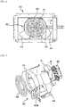
- FIG. 5 is a front view of rear wall 31.
- rear wall 31 is formed from a metallic plate having an approximately rectangular parallelepiped shape.
- the plurality of openings 38 formed on rear wall 31 includes first holes 38a that are punching holes formed in a group in an approximately circular shape on a central portion of rear wall 31 (central portion of heating chamber 4), and second holes 38b that are punching holes laterally formed in a group under first holes 38a.
- the group of second holes 38b is formed at a lower side in heating chamber 4 so as to be more widely distributed in a left-right direction than the group of first holes 38a.
- the group of first holes 38a formed on rear wall 31 functions as an air intake port into convection device 30, and the group of second holes 38b formed under the group of first holes 38a functions as a hot air blowing port from convection device 30.
- a diameter of each of punching holes formed on a heating chamber in a conventional convection oven falls within a range from 4 mm to 5 mm inclusive.
- a diameter of each of first holes 38a and second holes 38b forming openings 38 functioning as the air intake port and the hot air blowing port for convection device 30 is 10 mm, which is approximately twice of a diameter of punching holes in the conventional convection oven.
- hot air generation mechanism 39 formed from a plurality of members for generating hot air is provided in convection device 30.
- Hot air generation mechanism 39 has a function to take air in heating chamber 4, to heat the taken air to generate hot air, and to blow the hot air into heating chamber 4.
- hot air generation mechanism 39 supplies hot air into heating chamber 4 to generate a circulating flow of the hot air in heating chamber 4.
- a heating configuration of cooker 10 according to this exemplary embodiment can separately or simultaneously perform heating through radiation of heat using the grill heater provided on the ceiling wall side of heating chamber 4, heating with microwaves supplied from magnetrons 35 served as microwave generators, and heating through a circulating flow of hot air using hot air generation mechanism 39 of convection device 30.
- no heater lies under an object, a liquid such as a fat component dropping from the object does not come into contact with a heater served as a heat source, and thus neither smoke nor a fire occurs.
- FIG. 6 is a front view of convection device 30 provided behind rear wall 31 of heating chamber 4.
- FIG. 7 is an exploded perspective view of hot air generation mechanism 39 of convection device 30.
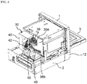
- FIG. 8 is a perspective view of the cooker according to this exemplary embodiment, when a housing served as a cover of main body 1 is removed to show, in a partial cross-sectional view, an arrangement of convection device 30 provided behind heating chamber 4.
- convection device 30 is illustrated in a partial cross-sectional view, and another configuration than the configuration of convection device 30 is omitted.
- Hot air generation mechanism 39 includes convection heater 40 provided immediately behind rear wall 31 of heating chamber 4, circulation fan 41, fan driver 42 for rotating and driving circulation fan 41, first and second hot air guides 43, 44 for guiding hot air in hot air generation mechanism 39.
- a sheath heater is used to configure convection heater 40 for heating air in convection device 30.
- Convection heater 40 is formed in a spiral shape at a central portion of convection device 30 (which corresponds to a central portion in the heating chamber) to increase an area coming into contact with air.
- Circulation fan 41 is a centrifugal fan that takes air in its central portion to blow the taken air in a centrifugal direction.
- the cooker according to this exemplary embodiment is configured such that, in the convection mode, circulation fan 41 takes air in heating chamber 4 into convection device 30 via openings 38 on rear wall 31 to blow the air in convection device 30 toward heating chamber 4.
- Circulation fan 41 is disposed behind convection heater 40, and is driven by fan driver 42 provided behind circulation fan 41.
- a case when circulation fan 41 rotates in a direction of arrow R (see FIG. 7 ) will be described. However, an identical function is achieved when circulation fan 41 rotates in an opposite direction.
- first hot air guide 43 is a guide member for guiding air taken into convection device 30 by circulation fan 41 to pass through an area around convection heater 40, and is disposed so as to surround convection heater 40.
- first hot air guide 43 is formed in an approximately cylindrical shape.
- First hot air guide 43 is formed with cut-away portion 43a for allowing an extended portion of convection heater 40 to extend from inside toward outside.
- Second hot air guide 44 is a member for guiding hot air blown in the centrifugal direction by circulation fan 41 toward a desired direction, and is disposed so as to externally surround circulation fan 41 and first hot air guide 43. In this exemplary embodiment, second hot air guide 44 partially abuts first hot air guide 43 outside of first hot air guide 43.
- fan driver 42 drives circulation fan 41 to take air in heating chamber 4 into convection device 30 via openings 38 (first holes 38a) on rear wall 31.
- the taken air is guided by first hot air guide 43 toward the area around convection heater 40 for being heated by convection heater 40.
- Circulation fan 41 takes the air heated by convection heater 40 (hot air) to blow the air in a spiral shape toward around circulation fan 41.
- the air blown around by circulation fan 41 is guided by second hot air guide 44, and then guided into a lower space formed on a lower side of a space between first hot air guide 43 and second hot air guide 44.
- the hot air guided by first hot air guide 43 and second hot air guide 44 in convection device 30 is blown into a lower side in heating chamber 4 via openings 38 (second holes 38b) on rear wall 31.
- first hot air guide 43 functions as a guide plate for separating the paths for taking and blowing air in convection device 30.
- convection device 30 As shown in FIG. 8 , convection device 30 according to this exemplary embodiment, which is configured as described above, is attached to rear wall 31 configuring a wall face on a rear of heating chamber 4. In convection device 30, convection heater 40 and circulation fan 41 are covered by convection device case 45 fixed to rear wall 31.
- the plurality of openings 38 (first holes 38a and second holes 38b) each having a diameter of 10 mm is formed on rear wall 31 of heating chamber 4 to significantly reduce a pressure loss when air passes through openings 38 on rear wall 31 in the convection mode.
- a diameter of each of punching holes formed in a heating chamber of a conventional convection oven ranges from 4 mm to 5 mm inclusive.
- openings 38 formed on rear wall 31 in this exemplary embodiment each have a diameter approximately twice the diameter of each of the punching holes in the conventional convection oven. Therefore, in the cooker according to this exemplary embodiment, a pressure loss is significantly reduced when hot air circulates, compared with the conventional convection oven.
- Cooker 10 includes a plurality of microwave leak suppression mechanisms described below in order to significantly reduce microwaves leaking outside of the cooker via convection device 30, but to highly effectively perform heat processing with the microwave-heating mode.
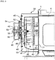
- FIG. 9 is a cross-sectional view of convection device 30 provided behind heating chamber 4, which is taken along a rotation central axis of circulation fan 41, when an outer housing covering heating chamber 4 is removed.
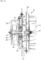
- FIG. 10 is an enlarged cross-sectional view illustrating a configuration of the convection-heating mechanism including circulation fan 41, fan driver 42, and circulation fan shaft 46 in convection device 30.
- convection heater 40 is provided behind rear wall 31 of heating chamber 4. Behind convection heater 40 having a spiral shape, circulation fan 41 having a rotation center approximately around convection heater 40 is provided.
- Circulation fan shaft 46 lying at the rotation center of circulation fan 41 is rotated and driven by a motor, i.e., fan driver 42.
- circulation fan 41 is fixed at a front end side of circulation fan shaft 46
- fan driver 42 served as the motor is provided at a rear end side of circulation fan shaft 46
- circulation fan shaft 46 is rotated and driven by fan driver 42.
- Circulation fan shaft 46 is rotatably held by two bearings 55 at a rear side at which fan driver 42 is provided.
- circulation fan shaft 46 is held by bearings 55 at only one side. This is because a front side (tip side) of circulation fan shaft 46 becomes hot due to transmitted heat and microwaves radiated from heating chamber 4, and thus no bearing can be provided on the front side (tip side).
- Convection space forming wall 50 served as a wall face provided immediately behind circulation fan 41 is provided behind rear wall 31. Convection space forming wall 50 and rear wall 31 form convection forming space A. Part of convection space forming wall 50 is served as second hot air guide 44 described above. Convection heater 40 and circulation fan 41 are provided in convection forming space A. Therefore, in convection forming space A, air taken from inside of heating chamber 4 is heated, and the heated air (hot air) is blown into heating chamber 4 (in this exemplary embodiment, the lower side in heating chamber 4).
- Convection forming space A formed by convection space forming wall 50 (including second hot air guide 44) served as a first wall is covered by convection device case 45 served as a second wall, and fan driver case 54 covering fan driver 42 is fixed to convection device case 45 served as the second wall. Therefore, other faces than a face (rear wall 31) facing heating chamber 4 in convection forming space A according to this exemplary embodiment are formed in a double wall structure.
- the plurality of microwave leak suppression mechanisms in convection device 30, which is configured as described above, is provided around circulation fan shaft 46 that rotates circulation fan 41.
- the plurality of microwave leak suppression mechanisms will now be described herein.
- a first microwave leak suppression mechanism is a coaxial seal mechanism formed based on a gap between convection space forming wall 50 served as the first wall provided behind circulation fan 41 and circulation fan shaft 46.
- a second microwave leak suppression mechanism follows the first microwave leak suppression mechanism, and is formed by leak suppression space B lying behind convection space forming wall 50 (see FIG. 10 ).
- a third microwave leak suppression mechanism follows the second microwave leak suppression mechanism, and is formed by microwave sealing space C.
- a fourth microwave leak suppression mechanism follows the third microwave leak suppression mechanism, and is a coaxial seal mechanism formed based on a gap around circulation fan shaft 46.
- the microwave leak suppression mechanisms are provided in convection device 30 in plural stages to significantly suppress a microwave leak from convection device 30 toward outside of the cooker. According to experiments and calculations performed by the inventors of the present disclosure with a cooker having a microwave output of 1300 W, even when microwaves having an output of 30 W enter into convection device 30 via the plurality of openings 38 on rear wall 31 of heating chamber 4, the microwave leak suppression mechanisms provided in convection device 30 in plural stages have reduced a microwave output at approximately 97 dB, where only an extremely smaller amount of microwaves having an output of approximately 0.4 mW has leaked.
- FIG. 11 is a cross-sectional view illustrating an area around the tip side (front end side) of circulation fan shaft 46 fixed with circulation fan 41.
- fan fastener 47 for fixing circulation fan 41 to circulation fan shaft 46 is screwed into a tip of circulation fan shaft 46.
- the central portion of circulation fan 41 is pinched and attached between fan support 48 secured around the tip side of circulation fan shaft 46 and holding plate 57.
- Fan support 48 having a T-shaped cross-section is passed through by circulation fan shaft 46 and is fixed to circulation fan shaft 46.
- Fan support 48 includes plain face portion 48a having a plain face that is orthogonal to a rotation central axis of circulation fan shaft 46, and cylindrical portion 48b integrally formed with and projecting rearward from a center of plain face portion 48a so as to closely fit to an outer periphery of circulation fan shaft 46. Therefore, circulation fan 41 inserted with a tip portion of circulation fan shaft 46 screwed with fan fastener 47 into the tip portion of circulation fan shaft 46 is pinched between holding plate 57 and plain face portion 48a of fan support 48, and is securely fixed to circulation fan shaft 46.
- first bushing 49 is provided in a through hole of convection space forming wall 50 served as the first wall into which circulation fan shaft 46 passes through.
- First bushing 49 having a through hole at its center and formed in an annular shape is attached so as to cover an inner peripheral surface of the through hole of convection space forming wall 50 into which circulation fan shaft 46 passes through.
- First bushing 49 has a face opposing an outer face of fan support 48 with a predetermined distance interposed.
- First bushing 49 has a front end (an end in a direction toward which circulation fan 41 is provided) formed in a flat face.
- the flat face hereinafter will refer to opposing Y plain face 49y.
- First bushing 49 has the through hole into which cylindrical portion 48b of fan support 48 abutting an outer peripheral surface of circulation fan shaft 46 passes through.
- An inner peripheral surface of the through hole of first bushing 49 is regarded as opposing X plain face 49x facing an outer peripheral surface of cylindrical portion 48b of fan support 48.
- fan support 48 a rear end face on plain face portion 48a facing opposing Y plain face 49y of first bushing 49 is regarded as opposing Y plain face 48y.
- the outer peripheral surface of cylindrical portion 48b on fan support 48 is regarded as opposing X plain face 48x.
- a distance between opposing faces refers to a minimum distance between opposing faces.
- a minimum distance in a left-right direction in a vertically extending gap between opposing Y plain faces 48y and 49y represents a distance between opposing faces
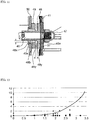
- a minimum distance in a upper-lower direction in a horizontally extending gap between opposing X plain faces 48x and 49x represents another distance between opposing faces.
- the gap between opposing Y plain faces 48y and 49y (between opposing faces) is set to 1.5 mm, and the gap between opposing X plain faces 48x and 49x (between opposing faces) is also set to 1.5 mm.
- the gap between opposing Y plain faces 48y and 49y (between opposing faces), and the gap between opposing X plain faces 48x and 49x (between opposing faces) are set to 1.5 mm.
- a distance is as short as possible.
- circulation fan shaft 46 is held by bearings 55 provided only at a rear side, a gap of 1.0 mm or greater is preferable by taking into account vibration when the shaft rotates, and, in reality, the gap can be formed in a range from 0.8 mm to 1.2 mm inclusive.
- FIG. 12 is a graph rendered based on results of experiments regarding gaps (distances between opposing faces) and microwave leak power, as described above, where a vertical axis shows the microwave leak power [W], and a horizontal axis shows the gap between opposing Y plain faces 48y and 49y (distance between opposing faces) [mm].
- FIG. 12 shows the results of experiments based on various samples in which a distance between opposing faces varies.
- the microwave leak power increases greater when the gap exceeds 3.0 mm. Therefore, a preferable distance between opposing faces for securely suppressing a microwave leak is 3.0 mm or smaller.
- a more preferable distance between opposing faces is 2.0 mm or smaller.
- a distance between opposing faces of 1.0 mm or smaller can lead to a superior effect of suppressing a microwave leak to less than 0.5 W.
- the second microwave leak suppression mechanism follows the first microwave leak suppression mechanism described above, and suppresses a microwave leak of microwave power leaked from the first microwave leak suppression mechanism by leak suppression space B (see FIGS. 9 and 10 ) formed behind convection space forming wall 50.
- Leak suppression space B is a space formed to surround circulation fan shaft 46 with leak suppression wall 51 provided so as to join convection space forming wall 50 served as the first wall and convection device case 45 served as the second wall.
- Leak suppression space B is closed in its outer direction by leak suppression wall 51 so that convection space forming wall 50 forms a front wall face and convection device case 45 forms a back wall face.
- microwaves leaked from the first microwave leak suppression mechanism interfere to each other to reduce microwave power.
- the third microwave leak suppression mechanism is formed behind leak suppression space B configuring the second microwave leak suppression mechanism, and is formed by a metal mesh seal mechanism.
- FIG. 13 is a cross-sectional view of the metal mesh seal mechanism of the third microwave leak suppression mechanism formed behind leak suppression space B.
- metal mesh seal 52 is provided to closely fit to convection device case 45 forming a back wall of leak suppression space B.
- metal mesh seal 52 is formed by gathering stainless steel mesh wires, and is disposed in an annular shape around circulation fan shaft 46. In FIG. 13 and other figures, metal mesh seal 52 is simplified.
- Metal mesh seal 52 is formed by gathering mesh wires, and thus is an elastic body wholly having elasticity. Therefore, metal mesh seal 52 is pressed and securely fixed by seal pressure plate 53 fixed to convection device case 45 by means of a fastener such as a screw.
- a seal of metal mesh seal 52 is not limited to a metal mesh, and a metallic contact seal may be adopted to secure a similar performance.
- the third microwave leak suppression mechanism uses metal mesh seal 52 to seal microwaves leaked from leak suppression space B of the second microwave leak suppression mechanism via a through hole on convection device case 45, into which circulation fan shaft 46 passes through.
- Metal mesh seal 52 is pressed and fixed by seal pressure plate 53, into which circulation fan shaft 46 passes through, onto convection device case 45 served as the second wall.
- Microwave sealing space C is substantially formed inside of metal mesh seal 52 by seal pressure plate 53. In other words, microwave sealing space C is formed by convection device case 45, metal mesh seal 52, and seal pressure plate 53.
- the fourth microwave leak suppression mechanism follows the metal mesh seal mechanism served as the third microwave leak suppression mechanism.
- the fourth microwave leak suppression mechanism is a coaxial seal mechanism formed by second bushing 56 provided to have a predetermined gap with respect to the outer peripheral surface of circulation fan shaft 46.
- seal pressure plate 53 for pressing and fixing metal mesh seal 52 onto a rear face (back face) of convection device case 45 has projection 53a formed in a projected shape toward a front side from around circulation fan shaft 46. Therefore, projection 53a of seal pressure plate 53 is disposed at a central portion of metal mesh seal 52 disposed in an annular shape around circulation fan shaft 46.
- the fourth microwave leak suppression mechanism is formed by second bushing 56 made of a metal and provided to face the outer peripheral surface of circulation fan shaft 46 passing through projection 53a of seal pressure plate 53.
- second bushing 56 is made of aluminum.
- second bushing 56 may be made of any metal, as long as the metal is a conductor.
- a gap between the outer peripheral surface of circulation fan shaft 46 and an inner peripheral surface of second bushing 56 has been set to 0.5 mm. Similar to the first microwave leak suppression mechanism (coaxial seal mechanism) described above, a smaller distance between opposing faces is preferable, and a distance between opposing faces, i.e., between the outer peripheral surface of circulation fan shaft 46 and the inner peripheral surface of second bushing 56, of 0.5 mm is a distance that significantly reduces a microwave leak.
- a preferable distance between opposing faces, i.e., between the outer peripheral surface of circulation fan shaft 46 and the inner peripheral surface of second bushing 56, is 1.0 mm or smaller as described above for suppressing a microwave leak.
- the fourth microwave leak suppression mechanism has been formed to have a length of 10 mm between opposing faces in the axial direction in the coaxial seal mechanism formed by circulation fan shaft 46 and second bushing 56. However, a longer length in this axial direction is preferable.
- the above cooker according to the exemplary embodiment has been described to have a configuration where hot air formed in convection device 30 is blown toward the lower side in heating chamber 4.
- the present disclosure is not limited to such a configuration, but may be a configuration where hot air is blown toward the upper side (ceiling side) of heating chamber 4.
- the cooker configured as described above can be configured to circulate, with the convection mode, hot air heated by at least one of convection heater 40 of convection device 30 and the grill heater provided on the ceiling side of heating chamber 4.
- the present disclosure has a configuration applicable to cookers for heating and cooking an object, and in particular to high-speed cookers such as commercial microwave ovens having a microwave-heating mode and a convection mode, which are used in, for example, stores and restaurants such as convenience stores and fast-food restaurants.
Landscapes
- Physics & Mathematics (AREA)
- Electromagnetism (AREA)
- Engineering & Computer Science (AREA)
- Chemical & Material Sciences (AREA)
- Combustion & Propulsion (AREA)
- Mechanical Engineering (AREA)
- General Engineering & Computer Science (AREA)
- Electric Ovens (AREA)
- Constitution Of High-Frequency Heating (AREA)
Abstract
Description
- The present disclosure relates to cookers used to microwave-heat an object by radiating microwaves, and, in particular, relates to a commercial cooker used as a cooking apparatus in commercial facilities including stores and restaurants such as convenience stores and fast-food restaurants.
- In order to be able to respond to various menus, commercial cookers used in stores and restaurants such as convenience stores and fast-food restaurants are configured to include, in addition to a microwave-heating mode with which an object is heat cooked by radiating microwaves, a grill mode with which the object is heat cooked through radiation heating using a heater, and a convection mode with which the object is heat cooked by using a fan to circulate air heated by the heater in a convection manner in a heating chamber. The commercial cookers used in stores and restaurants are required to securely execute each heating process for heat cooking at a precise temperature and a precise time. In addition, for the commercial cookers, shortening a cooking time is important to promptly respond to an order of a customer. To achieve such requirements, the commercial cookers having a greater high-frequency output for microwave-heating are used, and a heater that consumes greater power is often used as a heating source in the grill mode and the convection mode.
- As described above, in the commercial cookers, various devices having a greater output are used to shorten a cooking time. In particular, the commercial cookers capable of simultaneously executing the microwave-heating mode with which microwaves are irradiated and at least one of the grill mode and the convection mode are required to highly effectively use devices having a greater output to shorten a cooking time.
- Controlling a speed of a circulation fan in accordance with a type of an object and a heating method is also proposed (e.g., see PTL 1).
- PTL 1: Unexamined Japanese Patent Publication No.
2006-275390 - The present disclosure has an object to provide a cooker at least having a microwave-heating mode and a convection mode, which is capable of highly effectively performing heat cooking with the microwave-heating mode by suppressing a microwave leak in a mechanism for executing the convection mode to shorten a cooking time during the microwave-heating mode.
- A cooker according to an aspect of the present disclosure includes a heating chamber configured to accommodate and heat an object, a microwave-heating mechanism configured to form microwaves and radiate the microwaves into the heating chamber to heat the object with the microwave-heating mode, a convection-heating mechanism configured to heat the object with the convection mode, and a microwave leak suppression mechanism configured to suppress a microwave leak. The convection-heating mechanism includes a circulation fan for taking air from the heating chamber and for blowing the air into the heating chamber, a convection heater for heating the air taken from the heating chamber by the circulation fan, a hot air guide for guiding the air taken from the heating chamber by the circulation fan toward the convection heater, and for guiding a direction of the hot air blown into the heating chamber by the circulation fan toward a desired position in the heating chamber, and a fan driver for driving a circulation fan shaft for rotating the circulation fan. The convection heater and the circulation fan are disposed in a convection forming space that is in communication with the heating chamber. The fan driver is disposed outside of the convection forming space. The microwave leak suppression mechanism has a coaxial seal mechanism for forming a gap between the circulation fan shaft passing through a first wall forming the convection forming space and the first wall and setting the gap between opposing faces of the circulation fan shaft and the first wall to a predetermined distance or smaller, and suppresses a microwave leak from the convection forming space.
- According to the present disclosure, a leak of microwaves radiated in the heating chamber during heat cooking with the microwave-heating mode from a mechanism for executing heat cooking with the convection mode can significantly be suppressed. Therefore, the cooker for highly effectively performing heat cooking with the microwave-heating mode can be provided.
-
-
FIG. 1 is a perspective view of a cooker according to an exemplary embodiment of the present disclosure when its door is closed. -
FIG. 2 is a perspective view of the cooker according to the exemplary embodiment of the present disclosure when its door is open. -
FIG. 3 is a front view of the cooker according to the exemplary embodiment of the present disclosure when its door is open. -
FIG. 4 is a vertical cross-sectional view of the cooker according to the exemplary embodiment of the present disclosure. -
FIG. 5 is a front view of a rear wall of a heating chamber in the cooker according to the exemplary embodiment of the present disclosure. -
FIG. 6 is a front view of a convection device placed behind the heating chamber of the cooker according to the exemplary embodiment of the present disclosure. -
FIG. 7 is an exploded perspective view of the convection device of the cooker according to the exemplary embodiment of the present disclosure. -
FIG. 8 is a perspective view of the cooker according to the exemplary embodiment of the present disclosure, when a housing is removed to show an arrangement of the convection device. -
FIG. 9 is a cross-sectional view of the convection device of the cooker according to the exemplary embodiment of the present disclosure, which is taken along a rotation central axis of a circulation fan. -
FIG. 10 is an enlarged cross-sectional view illustrating a configuration of the convection device of the cooker according to the exemplary embodiment of the present disclosure. -
FIG. 11 is a cross-sectional view illustrating an area around a front end side of a circulation fan shaft fixed with the circulation fan of the cooker according to the exemplary embodiment of the present disclosure. -
FIG. 12 is a graph rendered based on results of experiments using the cooker according to the exemplary embodiment of the present disclosure. -
FIG. 13 is a cross-sectional view of a metal mesh seal mechanism of a microwave leak suppression mechanism and other components of the cooker according to the exemplary embodiment of the present disclosure. - A cooker according to a first aspect of the present disclosure includes a heating chamber configured to accommodate and heat an object, a microwave-heating mechanism configured to form microwaves and radiate the microwaves into the heating chamber to heat the object with a microwave-heating mode, a convection-heating mechanism configured to heat the object in a convection mode, and a microwave leak suppression mechanism configured to suppress a microwave leak. The convection-heating mechanism includes a circulation fan for taking air from the heating chamber and for blowing the air into the heating chamber, a convection heater for heating the air taken from the heating chamber by the circulation fan, a hot air guide for guiding the air taken from the heating chamber by the circulation fan toward the convection heater, and for guiding a direction of the hot air blown into the heating chamber by the circulation fan toward a desired position in the heating chamber, and a fan driver for driving a circulation fan shaft for rotating the circulation fan. The convection heater and the circulation fan are disposed in a convection forming space that is in communication with the heating chamber. The fan driver is disposed outside of the convection forming space. The microwave leak suppression mechanism has a coaxial seal mechanism for forming a gap between the circulation fan shaft passing through a first wall forming the convection forming space and the first wall and setting the gap between opposing faces to a predetermined distance or smaller, and suppresses a microwave leak from the convection forming space.
- As described above, the cooker according to the first aspect of the present disclosure configured to have the microwave-heating mode and the convection mode can suppress a microwave leak in the convection-heating mechanism for executing the convection mode. Therefore, heat cooking with the microwave-heating mode can highly effectively be performed to shorten a cooking time during the microwave-heating mode.
- In a cooker according to a second aspect of the present disclosure, in the first aspect, the gap between opposing faces, i.e., between the circulation fan shaft and the first wall, may be 3.0 mm or smaller.
- In a cooker according to a third aspect of the present disclosure, in the second aspect, the microwave leak suppression mechanism may include a fan support for fixing the circulation fan at a predetermined position with respect to the circulation fan shaft, and an annular first bushing fixed so as to cover an inner face of a through hole on the first wall, into which the circulation fan shaft passes through. In addition, with the fan support being passed through the first bushing, a gap between opposing faces, i.e., between the fan support and the first bushing, may be 3.0 mm or smaller.
- In a cooker according to a fourth aspect of the present disclosure, the fan support in the third aspect may include a plain face portion having a plain face for fixing the circulation fan at a predetermined position, and a cylindrical portion for covering an outer peripheral surface of the circulation fan shaft that is orthogonal to the plain face of the plain face portion. A gap between opposing faces, i.e., between an inner peripheral surface of the first bushing and an outer peripheral surface of the cylindrical portion, may be 3.0 mm or smaller, and a gap between opposing faces, i.e., between the first bushing and the plain face portion, may be 3.0 mm or smaller.
- In a cooker according to a fifth aspect of the present disclosure, a second wall for covering the first wall forming the convection forming space in the fourth aspect with a space interposed may be included. In addition, the circulation fan shaft may pass through the first wall and the second wall, the fan driver may join the circulation fan shaft passing through the second wall, and other faces than a face facing the heating chamber in the convection forming space may be configured in a double wall structure.
- In a cooker according to a sixth aspect of the present disclosure, as the microwave leak suppression mechanism in the fifth aspect, a leak suppression space surrounding the circulation fan shaft with a leak suppression wall provided to join the first wall and the second wall may be formed.
- In a cooker according to a seventh aspect of the present disclosure, as the microwave leak suppression mechanism in the fifth aspect, a metal mesh seal provided in an annular shape around the circulation fan shaft passing through the second wall may be provided on a side of the second wall, on which the fan driver is provided.
- In a cooker according to an eighth aspect of the present disclosure, the metal mesh seal in the seventh aspect may be pressed and fixed onto the second wall by a seal pressure plate into which the circulation fan shaft passes through, and the seal pressure plate may form a microwave sealing space inside of the metal mesh seal.
- In a cooker according to a ninth aspect of the present disclosure, as the microwave leak suppression mechanism in the eighth aspect, a second bushing having a coaxial seal function, which is fixed to the seal pressure plate and disposed on the outer peripheral surface of the circulation fan shaft to have a predetermined gap, may be provided.
- In a cooker according to a tenth aspect of the present disclosure, in the ninth aspect, a gap between opposing faces, i.e., between an inner peripheral surface of the second bushing and the outer peripheral surface of the circulation fan shaft, may be 1.0 mm or smaller.
- A cooker according to an exemplary embodiment of the present disclosure, which is capable of executing a microwave-heating mode, a grill mode and a convection mode, will now be described herein. In particular, in the exemplary embodiment described below, the cooker that is a commercial microwave oven used in stores and restaurants such as convenience stores and fast-food restaurants will now be described herein with reference to the accompanied drawings. A configuration of the cooker according to the present disclosure is not limited to a configuration of the commercial microwave oven described in the below exemplary embodiment, but includes a configuration of a cooker based on a technical idea equivalent to a technical idea described in the below exemplary embodiment.
- The commercial cooker according to the exemplary embodiment of the present disclosure will now be described herein with reference to the accompanied drawings. Note however that some or all of the drawings are schematically rendered for illustration purpose, and components shown in the drawings do not always indicate their actual relative sizes and positions.
-
FIG. 1 is a perspective view illustrating an appearance ofcooker 10 according to the exemplary embodiment of the present disclosure when its door formed on a front face ofcooker 10 is closed. InFIG. 2 , the door ofcooker 10 shown inFIG. 1 is open, and thus a heating chamber formed incooker 10 is open. - Cooker 10 according to this exemplary embodiment is a commercial microwave oven used in stores and restaurants, in particular, used in convenience stores and fast-food restaurants, has a maximum output of approximately 2000 W, and is configured to be capable of switching an output in plural steps.
- As shown in
FIGS. 1 and2 ,cooker 10 includesmain body 1 configuring an outer case ofheating chamber 4,machine chamber 2 provided undermain body 1 so as to supportmain body 1, anddoor 3 attached on a front face side ofmain body 1. Detachablefront grille panel 12 is provided on a front face side ofmachine chamber 2. - As shown in
FIG. 2 ,heating chamber 4 is formed inside ofmain body 1.Heating chamber 4 is a space formed in an approximately rectangular parallelepiped shape having an opening on its front face side (door side) for internally accommodating an object. In the following description, the side ofheating chamber 4, on which the opening is formed, is defined as a front side ofcooker 10, and a back side ofheating chamber 4 is defined as a rear side ofcooker 10. A right side ofcooker 10 whencooker 10 is viewed from front is simply referred to as a right side, and a left side ofcooker 10 whencooker 10 is viewed from front is simply referred to as a left side. -
Door 3 is vertically openably attached on the front face side ofmain body 1 so as to cover the opening on a front ofheating chamber 4.Door 3 is configured in such a manner that a user holdshandle 5 provided ondoor 3 to open orclose door 3. Whendoor 3 is closed as shown inFIG. 1 ,heating chamber 4 is internally formed in a closed space so that an accommodated object is heat processed with microwaves, for example. Whendoor 3 is open as shown inFIG. 2 , the user can put or remove an object into or fromheating chamber 4. - In
cooker 10 according to this exemplary embodiment,operation unit 6 is provided on a right side of a front face ofmain body 1.Operation unit 6 is provided with operation buttons for setting a processing condition for heat cooking incooker 10, and a display screen. - As shown in
FIG. 2 ,heating chamber 4 is internally disposed withtray 7 made of ceramics (specifically, made of cordierite (made of ceramics composed of 2MgO ·2A1203 ·5SiO2)), andwire rack 8 made of stainless steel in an accommodatable manner.Wire rack 8 is a loading portion formed from a mesh member for loading an object, and allows hot air to effectively circulate under the object.Tray 7 is provided underwire rack 8 to catch fat components, for example, dropping from the object onwire rack 8. - In
cooker 10 according to this exemplary embodiment,machine chamber 2 underheating chamber 4 is provided with magnetron 35 (seeFIG. 4 described later) served as a microwave generator. Microwaves generated frommagnetron 35 radiate, via a wave guide, from microwave radiation holes formed on the wave guide and openings formed on a bottom face side ofheating chamber 4. The microwaves radiated from the microwave radiation holes on the wave guide and the openings formed on a bottom face ofheating chamber 4 intoheating chamber 4 will be stirred by a stir (agitator). By the cooker configured as described above, the object accommodated inheating chamber 4 can be microwave heated. - In
cooker 10 according to this exemplary embodiment, a grill heater formed based on a sheath heater is provided on a ceiling side ofheating chamber 4 so that a grill mode is executed to directly heat the object inheating chamber 4 with radiant heat of the grill heater. - In addition, convection device 30 (described later, see the cross-sectional view shown in
FIG. 4 ) configured to supply hot air intoheating chamber 4 is provided behind a rear wall ofheating chamber 4.Convection device 30 has a function to take air from a central portion ofheating chamber 4, to heat the taken air, and to blow the hot air intoheating chamber 4. As described above,convection device 30 supplies hot air intoheating chamber 4, and the hot air causes a circulating flow to occur inheating chamber 4. For example,convection device 30 takes air from a central area ofheating chamber 4, heats the taken air, and blows the hot air from a front side of the bottom face and a front side of a ceiling intoheating chamber 4 to circulate the hot air. -
FIG. 3 is a front view ofcooker 10 according to this exemplary embodiment whendoor 3 is open, and illustrates thatconvection device 30 is provided behindrear wall 31 ofheating chamber 4. - As described above,
cooker 10 according to this exemplary embodiment is configured to be capable of separately or simultaneously performing heating with microwaves supplied frommagnetron 35 served as a microwave generator, heating through radiation of heat using the grill heater provided on an upper side (ceiling wall side) ofheating chamber 4, and heating through a circulating flow of hot air usingconvection device 30. -
Cooker 10 according to this exemplary embodiment is configured such that a heater that is a larger heat source does not lie under the object accommodated inheating chamber 4. Therefore, a liquid such as a fat component dropping from the object does not come into contact with a heater, and thus a highly safe cooker can be achieved, where neither smoke nor a fire occurs. -
Machine chamber 2 is internally provided withcomponents including magnetron 35 served as a microwave generator for generating microwaves, inverter 36 (seeFIG. 4 ) for drivingmagnetron 35, and cooling fan 37 (seeFIG. 4 ) for coolingmagnetron 35,inverter 36, and other components. - In this exemplary embodiment, two
magnetrons 35 are used, and a total output ranges from 1200 W to 1300 W inclusive. Microwaves output from the two magnetrons respectively transmit into two wave guides, and radiate intoheating chamber 4 via microwave radiation openings respectively formed on the wave guides and openings formed on the bottom face ofheating chamber 4. The microwaves are stirred bystir 32, and radiated intoheating chamber 4. -
Inverter 36 drives each ofmagnetrons 35. Twoinverters 36 for respectively driving twomagnetrons 35 are provided inmachine chamber 2. Inmachine chamber 2, a plurality of coolingfans 37 is also disposed for respectively coolingmagnetrons 35 andinverters 36. In this exemplary embodiment, four coolingfans 37 are provided to form two pairs. Coolingfans 37 respectively take outside air fromfront grille panel 12 provided on a front face ofmachine chamber 2, and blow the taken outside air rearward to sequentially cool two pairs ofinverters 36 andmagnetrons 35 and other components arranged in a file to form the microwave-heating mechanism provided inmachine chamber 2. - A power supply circuit board is provided in
machine chamber 2, and a cooling fan for cooling the power supply circuit board is further provided. Upon the cooling fan starts, outside air is taken fromfront grille panel 12 provided on the front face ofmachine chamber 2 to cool various devices including the power supply circuit board inmachine chamber 2. - In this exemplary embodiment, four cooling
fans 37 arranged in parallel to cool heating portions ofinverters 36 andmagnetrons 35 and other components and the cooling fan for cooling the power supply circuit board is formed by multi-blade fans installed so that their rotation axes align in a straight line. The cooling fans are configured to take air in an axial direction of each of the rotation axes, and to blow the air toward a rear ofmachine chamber 2 in an outer peripheral direction. The air blown toward the rear ofmachine chamber 2 passes through an exhaust duct disposed on a rear face ofmain body 1 and a gap between a ceiling wall ofheating chamber 4 and an upper face wall ofmain body 1, and exits from the front face side ofmain body 1. As described above, air flowing from the cooling fans prevents the upper face wall around a rear wall ofmain body 1 from being heated. - An internal structure of
cooker 10 will now be described herein with reference toFIG. 4. FIG. 4 is a vertical cross-sectional view ofcooker 10 when viewed in a front-rear direction, in which the front side (front) faces rightward inFIG. 4 . - As shown in
FIG. 4 ,tray 7 is loaded ontray stand 22. Tray stand 22 is provided on the bottom face ofheating chamber 4 to supporttray 7. In this exemplary embodiment, tray stand 22 is made of a ceramics plate material that allows microwaves to pass through. - Stir (agitator) 32 for stirring microwaves to be radiated into
heating chamber 4 is provided between tray stand 22 and the bottom face ofheating chamber 4.Stir 32 is a rotor blade configured to rotate aboutstir shaft 33 to stir microwaves.Motor 34 is provided inmachine chamber 2 to rotate and drivestir 32. -
Machine chamber 2 is internally provided with the microwave-heatingmechanism including magnetrons 35 served as microwave generators for generating microwaves,inverters 36 for drivingmagnetrons 35, and coolingfans 37 for coolingmagnetrons 35 andinverters 36. - In this exemplary embodiment, as described above, two pairs of
magnetrons 35 andinverters 36 are provided for generating a higher output, and four coolingfans 37cool magnetrons 35 andinverters 36. - The plurality of cooling fans 37 (in this exemplary embodiment, four cooling fans 37) provided in
machine chamber 2cool magnetrons 35 andinverters 36, andsingle cooling fan 37 cools the power supply circuit board disposed inmachine chamber 2 and other components. Upon coolingfans 37 start, outside air is taken fromfront grille panel 12 attached on the front face ofmachine chamber 2, passes through an outside air intake port formed on the front face ofmachine chamber 2, and is then taken intomachine chamber 2. The air taken intomachine chamber 2 cools members inmachine chamber 2, passes through the exhaust duct disposed on the rear face ofmain body 1 and the gap between the ceiling wall ofheating chamber 4 and the upper face wall ofmain body 1, and exits from the front face side ofmain body 1. - A plurality of
openings 38 is formed on rear wall 31 (seeFIG. 5 described later) configuring a back wall ofheating chamber 4.Openings 38 onrear wall 31 in this exemplary embodiment are a plurality of punching holes formed through punching onrear wall 31 made of a plate material.Convection device 30 configured to take air inheating chamber 4, to heat the air to generate hot air, and to blow the hot air intoheating chamber 4 is provided behindrear wall 31. A space in whichconvection device 30 is disposed is separated from an inner space ofheating chamber 4 byrear wall 31, and is in communication with the inner space ofheating chamber 4 through the plurality ofopenings 38 formed onrear wall 31. In this exemplary embodiment,convection device 30 is served as a convection-heating mechanism. -
FIG. 5 is a front view ofrear wall 31. As shown inFIG. 5 ,rear wall 31 is formed from a metallic plate having an approximately rectangular parallelepiped shape. The plurality ofopenings 38 formed onrear wall 31 includesfirst holes 38a that are punching holes formed in a group in an approximately circular shape on a central portion of rear wall 31 (central portion of heating chamber 4), andsecond holes 38b that are punching holes laterally formed in a group underfirst holes 38a. On a plain face (front) ofrear wall 31, the group ofsecond holes 38b is formed at a lower side inheating chamber 4 so as to be more widely distributed in a left-right direction than the group offirst holes 38a. - As will be described later, the group of
first holes 38a formed onrear wall 31 functions as an air intake port intoconvection device 30, and the group ofsecond holes 38b formed under the group offirst holes 38a functions as a hot air blowing port fromconvection device 30. - A diameter of each of punching holes formed on a heating chamber in a conventional convection oven falls within a range from 4 mm to 5 mm inclusive. In this exemplary embodiment, a diameter of each of
first holes 38a andsecond holes 38b forming openings 38 functioning as the air intake port and the hot air blowing port forconvection device 30 is 10 mm, which is approximately twice of a diameter of punching holes in the conventional convection oven. As described above, by increasing the diameter ofopenings 38, a pressure loss in air passing throughopenings 38 can significantly be reduced, and a hot air circulation mechanism having a higher efficiency in a convection mode can be constructed. - As shown in
FIG. 6 , hotair generation mechanism 39 formed from a plurality of members for generating hot air is provided inconvection device 30. Hotair generation mechanism 39 has a function to take air inheating chamber 4, to heat the taken air to generate hot air, and to blow the hot air intoheating chamber 4. As described above, hotair generation mechanism 39 supplies hot air intoheating chamber 4 to generate a circulating flow of the hot air inheating chamber 4. - A heating configuration of
cooker 10 according to this exemplary embodiment can separately or simultaneously perform heating through radiation of heat using the grill heater provided on the ceiling wall side ofheating chamber 4, heating with microwaves supplied frommagnetrons 35 served as microwave generators, and heating through a circulating flow of hot air using hotair generation mechanism 39 ofconvection device 30. In the configuration according to this exemplary embodiment, no heater lies under an object, a liquid such as a fat component dropping from the object does not come into contact with a heater served as a heat source, and thus neither smoke nor a fire occurs. - Next, a configuration of
convection device 30 served as the convection-heating mechanism incooker 10 according to this exemplary embodiment will now be described herein. -
FIG. 6 is a front view ofconvection device 30 provided behindrear wall 31 ofheating chamber 4.FIG. 7 is an exploded perspective view of hotair generation mechanism 39 ofconvection device 30.FIG. 8 is a perspective view of the cooker according to this exemplary embodiment, when a housing served as a cover ofmain body 1 is removed to show, in a partial cross-sectional view, an arrangement ofconvection device 30 provided behindheating chamber 4. InFIG. 8 , to show the configuration ofconvection device 30,convection device 30 is illustrated in a partial cross-sectional view, and another configuration than the configuration ofconvection device 30 is omitted. - Hot
air generation mechanism 39 includesconvection heater 40 provided immediately behindrear wall 31 ofheating chamber 4,circulation fan 41,fan driver 42 for rotating and drivingcirculation fan 41, first and second hot air guides 43, 44 for guiding hot air in hotair generation mechanism 39. - A sheath heater is used to configure
convection heater 40 for heating air inconvection device 30.Convection heater 40 is formed in a spiral shape at a central portion of convection device 30 (which corresponds to a central portion in the heating chamber) to increase an area coming into contact with air. -
Circulation fan 41 is a centrifugal fan that takes air in its central portion to blow the taken air in a centrifugal direction. The cooker according to this exemplary embodiment is configured such that, in the convection mode,circulation fan 41 takes air inheating chamber 4 intoconvection device 30 viaopenings 38 onrear wall 31 to blow the air inconvection device 30 towardheating chamber 4.Circulation fan 41 is disposed behindconvection heater 40, and is driven byfan driver 42 provided behindcirculation fan 41. In this exemplary embodiment, a case whencirculation fan 41 rotates in a direction of arrow R (seeFIG. 7 ) will be described. However, an identical function is achieved whencirculation fan 41 rotates in an opposite direction. - In
FIG. 7 , firsthot air guide 43 is a guide member for guiding air taken intoconvection device 30 bycirculation fan 41 to pass through an area aroundconvection heater 40, and is disposed so as to surroundconvection heater 40. In this exemplary embodiment, firsthot air guide 43 is formed in an approximately cylindrical shape. Firsthot air guide 43 is formed with cut-awayportion 43a for allowing an extended portion ofconvection heater 40 to extend from inside toward outside. - Second
hot air guide 44 is a member for guiding hot air blown in the centrifugal direction bycirculation fan 41 toward a desired direction, and is disposed so as to externally surroundcirculation fan 41 and firsthot air guide 43. In this exemplary embodiment, secondhot air guide 44 partially abuts firsthot air guide 43 outside of firsthot air guide 43. - In
cooker 10 according to this exemplary embodiment, which is configured as described above, upon the convection mode starts,fan driver 42 drivescirculation fan 41 to take air inheating chamber 4 intoconvection device 30 via openings 38 (first holes 38a) onrear wall 31. The taken air is guided by firsthot air guide 43 toward the area aroundconvection heater 40 for being heated byconvection heater 40. -
Circulation fan 41 takes the air heated by convection heater 40 (hot air) to blow the air in a spiral shape toward aroundcirculation fan 41. The air blown around bycirculation fan 41 is guided by secondhot air guide 44, and then guided into a lower space formed on a lower side of a space between firsthot air guide 43 and secondhot air guide 44. The hot air guided by firsthot air guide 43 and secondhot air guide 44 inconvection device 30 is blown into a lower side inheating chamber 4 via openings 38 (second holes 38b) onrear wall 31. - As described above, a path for taking air from
first holes 38a ofopenings 38 onrear wall 31 tocirculation fan 41 is formed in a space surrounded by firsthot air guide 43. A path for blowing hot air fromcirculation fan 41 tosecond holes 38b ofopenings 38 onrear wall 31 is formed in a space between firsthot air guide 43 and secondhot air guide 44. As described above, firsthot air guide 43 functions as a guide plate for separating the paths for taking and blowing air inconvection device 30. - As shown in
FIG. 8 ,convection device 30 according to this exemplary embodiment, which is configured as described above, is attached torear wall 31 configuring a wall face on a rear ofheating chamber 4. Inconvection device 30,convection heater 40 andcirculation fan 41 are covered byconvection device case 45 fixed torear wall 31. - In
cooker 10 according to this exemplary embodiment, the plurality of openings 38 (first holes 38a andsecond holes 38b) each having a diameter of 10 mm is formed onrear wall 31 ofheating chamber 4 to significantly reduce a pressure loss when air passes throughopenings 38 onrear wall 31 in the convection mode. A diameter of each of punching holes formed in a heating chamber of a conventional convection oven ranges from 4 mm to 5 mm inclusive. In other words,openings 38 formed onrear wall 31 in this exemplary embodiment each have a diameter approximately twice the diameter of each of the punching holes in the conventional convection oven. Therefore, in the cooker according to this exemplary embodiment, a pressure loss is significantly reduced when hot air circulates, compared with the conventional convection oven. - As described above, in
cooker 10 according to this exemplary embodiment, since the plurality of openings 38 (first holes 38a andsecond holes 38b) formed onrear wall 31 ofheating chamber 4 has been formed to each have a greater diameter, an amount of microwaves radiated intoheating chamber 4 and passing throughopenings 38 onrear wall 31 falls within approximately 2.5% to 3% (around 30 W), when the microwave-heating mode is executed. If microwaves passed throughopenings 38 onrear wall 31 leak outside ofconvection device case 45, heating efficiency would significantly lower in heat processing with the microwave-heating mode. -
Cooker 10 according to this exemplary embodiment includes a plurality of microwave leak suppression mechanisms described below in order to significantly reduce microwaves leaking outside of the cooker viaconvection device 30, but to highly effectively perform heat processing with the microwave-heating mode. - The microwave leak suppression mechanisms of
convection device 30 according to this exemplary embodiment will now be described herein.FIG. 9 is a cross-sectional view ofconvection device 30 provided behindheating chamber 4, which is taken along a rotation central axis ofcirculation fan 41, when an outer housing coveringheating chamber 4 is removed.FIG. 10 is an enlarged cross-sectional view illustrating a configuration of the convection-heating mechanism includingcirculation fan 41,fan driver 42, andcirculation fan shaft 46 inconvection device 30. - As shown in
FIG. 9 ,convection heater 40 is provided behindrear wall 31 ofheating chamber 4. Behindconvection heater 40 having a spiral shape,circulation fan 41 having a rotation center approximately aroundconvection heater 40 is provided.Circulation fan shaft 46 lying at the rotation center ofcirculation fan 41 is rotated and driven by a motor, i.e.,fan driver 42. In this exemplary embodiment,circulation fan 41 is fixed at a front end side ofcirculation fan shaft 46,fan driver 42 served as the motor is provided at a rear end side ofcirculation fan shaft 46, andcirculation fan shaft 46 is rotated and driven byfan driver 42.Circulation fan shaft 46 is rotatably held by twobearings 55 at a rear side at whichfan driver 42 is provided. In other words, in this exemplary embodiment,circulation fan shaft 46 is held bybearings 55 at only one side. This is because a front side (tip side) ofcirculation fan shaft 46 becomes hot due to transmitted heat and microwaves radiated fromheating chamber 4, and thus no bearing can be provided on the front side (tip side). - Convection
space forming wall 50 served as a wall face provided immediately behindcirculation fan 41 is provided behindrear wall 31. Convectionspace forming wall 50 andrear wall 31 form convection forming space A. Part of convectionspace forming wall 50 is served as secondhot air guide 44 described above.Convection heater 40 andcirculation fan 41 are provided in convection forming space A. Therefore, in convection forming space A, air taken from inside ofheating chamber 4 is heated, and the heated air (hot air) is blown into heating chamber 4 (in this exemplary embodiment, the lower side in heating chamber 4). - Convection forming space A formed by convection space forming wall 50 (including second hot air guide 44) served as a first wall is covered by
convection device case 45 served as a second wall, andfan driver case 54 coveringfan driver 42 is fixed toconvection device case 45 served as the second wall. Therefore, other faces than a face (rear wall 31) facingheating chamber 4 in convection forming space A according to this exemplary embodiment are formed in a double wall structure. - The plurality of microwave leak suppression mechanisms in
convection device 30, which is configured as described above, is provided aroundcirculation fan shaft 46 that rotatescirculation fan 41. The plurality of microwave leak suppression mechanisms will now be described herein. - A first microwave leak suppression mechanism is a coaxial seal mechanism formed based on a gap between convection
space forming wall 50 served as the first wall provided behindcirculation fan 41 andcirculation fan shaft 46. A second microwave leak suppression mechanism follows the first microwave leak suppression mechanism, and is formed by leak suppression space B lying behind convection space forming wall 50 (seeFIG. 10 ). A third microwave leak suppression mechanism follows the second microwave leak suppression mechanism, and is formed by microwave sealing space C. In addition, a fourth microwave leak suppression mechanism follows the third microwave leak suppression mechanism, and is a coaxial seal mechanism formed based on a gap aroundcirculation fan shaft 46. - As described above, in the cooker according to this exemplary embodiment, the microwave leak suppression mechanisms are provided in
convection device 30 in plural stages to significantly suppress a microwave leak fromconvection device 30 toward outside of the cooker. According to experiments and calculations performed by the inventors of the present disclosure with a cooker having a microwave output of 1300 W, even when microwaves having an output of 30 W enter intoconvection device 30 via the plurality ofopenings 38 onrear wall 31 ofheating chamber 4, the microwave leak suppression mechanisms provided inconvection device 30 in plural stages have reduced a microwave output at approximately 97 dB, where only an extremely smaller amount of microwaves having an output of approximately 0.4 mW has leaked. - First, the first microwave leak suppression mechanism (coaxial seal mechanism) will now be described herein with reference to
FIG. 11. FIG. 11 is a cross-sectional view illustrating an area around the tip side (front end side) ofcirculation fan shaft 46 fixed withcirculation fan 41. - In
FIG. 11 ,fan fastener 47 for fixingcirculation fan 41 tocirculation fan shaft 46 is screwed into a tip ofcirculation fan shaft 46. By screwingfan fastener 47 into the tip ofcirculation fan shaft 46, the central portion ofcirculation fan 41 is pinched and attached betweenfan support 48 secured around the tip side ofcirculation fan shaft 46 and holdingplate 57. -
Fan support 48 having a T-shaped cross-section is passed through bycirculation fan shaft 46 and is fixed tocirculation fan shaft 46.Fan support 48 includesplain face portion 48a having a plain face that is orthogonal to a rotation central axis ofcirculation fan shaft 46, andcylindrical portion 48b integrally formed with and projecting rearward from a center ofplain face portion 48a so as to closely fit to an outer periphery ofcirculation fan shaft 46. Therefore,circulation fan 41 inserted with a tip portion ofcirculation fan shaft 46 screwed withfan fastener 47 into the tip portion ofcirculation fan shaft 46 is pinched between holdingplate 57 andplain face portion 48a offan support 48, and is securely fixed tocirculation fan shaft 46. - As shown in
FIG. 11 ,first bushing 49 is provided in a through hole of convectionspace forming wall 50 served as the first wall into whichcirculation fan shaft 46 passes through.First bushing 49 having a through hole at its center and formed in an annular shape is attached so as to cover an inner peripheral surface of the through hole of convectionspace forming wall 50 into whichcirculation fan shaft 46 passes through.First bushing 49 has a face opposing an outer face offan support 48 with a predetermined distance interposed.First bushing 49 has a front end (an end in a direction toward whichcirculation fan 41 is provided) formed in a flat face. The flat face hereinafter will refer to opposing Yplain face 49y.First bushing 49 has the through hole into whichcylindrical portion 48b offan support 48 abutting an outer peripheral surface ofcirculation fan shaft 46 passes through. An inner peripheral surface of the through hole offirst bushing 49 is regarded as opposing Xplain face 49x facing an outer peripheral surface ofcylindrical portion 48b offan support 48. - On the other hand, in
fan support 48, a rear end face onplain face portion 48a facing opposing Yplain face 49y offirst bushing 49 is regarded as opposing Yplain face 48y. The outer peripheral surface ofcylindrical portion 48b onfan support 48 is regarded as opposing Xplain face 48x. - As described above, between
fan support 48 andfirst bushing 49, opposing Y plain faces 48y and 49y, and opposing X plain faces 48x and 49x respectively are disposed to face each other with a predetermined gap interposed. Therefore,fan support 48 andfirst bushing 49 are provided to share the rotation central axis ofcirculation fan shaft 46 to configure a coaxial seal mechanism having a predetermined distance between opposing faces. In the present disclosure, a distance between opposing faces refers to a minimum distance between opposing faces. In this exemplary embodiment as shown inFIG. 11 , a minimum distance in a left-right direction in a vertically extending gap between opposing Y plain faces 48y and 49y represents a distance between opposing faces, and a minimum distance in a upper-lower direction in a horizontally extending gap between opposing X plain faces 48x and 49x represents another distance between opposing faces. - In the configuration according to this exemplary embodiment, the gap between opposing Y plain faces 48y and 49y (between opposing faces) is set to 1.5 mm, and the gap between opposing X plain faces 48x and 49x (between opposing faces) is also set to 1.5 mm.
- In this exemplary embodiment, as described above, an example is described, in which the gap between opposing Y plain faces 48y and 49y (between opposing faces), and the gap between opposing X plain faces 48x and 49x (between opposing faces) are set to 1.5 mm. However, it is preferable that a distance is as short as possible. However, as described above, in this exemplary embodiment, since
circulation fan shaft 46 is held bybearings 55 provided only at a rear side, a gap of 1.0 mm or greater is preferable by taking into account vibration when the shaft rotates, and, in reality, the gap can be formed in a range from 0.8 mm to 1.2 mm inclusive. According to experiments performed by the inventors of the present disclosure, it has been found that a basic performance can be secured as long as the gap between opposing Y plain faces 48y and 49y, and the gap between opposing X plain faces 48x and 49x are each 3.0 mm or smaller, in a worst case scenario. For example, as for a relation between the gap between opposing Y plain faces 48y and 49y and microwave leak power, results of experiments shown below have been obtained based on a plurality of samples. -
- When a gap (distance between opposing faces) is 1.5 mm: Microwave leak power is 0.68 W
- When a gap (distance between opposing faces) is 2.0 mm: Microwave leak power is 0.94 W
- When a gap (distance between opposing faces) is 2.2 mm: Microwave leak power is 1.20 W
- When a gap (distance between opposing faces) is 3.0 mm: Microwave leak power is 2.49 W
- When a gap (distance between opposing faces) is 3.2 mm: Microwave leak power is 7.85 W
- In the above described experiments and calculations, a cooker having a microwave output of 1300 W has been used, and a microwave power of 30 W has been leaked into convection forming space A of
convection device 30. -
FIG. 12 is a graph rendered based on results of experiments regarding gaps (distances between opposing faces) and microwave leak power, as described above, where a vertical axis shows the microwave leak power [W], and a horizontal axis shows the gap between opposing Y plain faces 48y and 49y (distance between opposing faces) [mm].FIG. 12 shows the results of experiments based on various samples in which a distance between opposing faces varies. As is apparent from the graph shown inFIG. 12 , the microwave leak power increases greater when the gap exceeds 3.0 mm. Therefore, a preferable distance between opposing faces for securely suppressing a microwave leak is 3.0 mm or smaller. A more preferable distance between opposing faces is 2.0 mm or smaller. Further preferably, a distance between opposing faces of 1.0 mm or smaller can lead to a superior effect of suppressing a microwave leak to less than 0.5 W. - The second microwave leak suppression mechanism follows the first microwave leak suppression mechanism described above, and suppresses a microwave leak of microwave power leaked from the first microwave leak suppression mechanism by leak suppression space B (see
FIGS. 9 and10 ) formed behind convectionspace forming wall 50. Leak suppression space B is a space formed to surroundcirculation fan shaft 46 withleak suppression wall 51 provided so as to join convectionspace forming wall 50 served as the first wall andconvection device case 45 served as the second wall. Leak suppression space B is closed in its outer direction byleak suppression wall 51 so that convectionspace forming wall 50 forms a front wall face andconvection device case 45 forms a back wall face. In the second microwave leak suppression mechanism configured as described above, microwaves leaked from the first microwave leak suppression mechanism interfere to each other to reduce microwave power. - The third microwave leak suppression mechanism is formed behind leak suppression space B configuring the second microwave leak suppression mechanism, and is formed by a metal mesh seal mechanism.
FIG. 13 is a cross-sectional view of the metal mesh seal mechanism of the third microwave leak suppression mechanism formed behind leak suppression space B. - As shown in
FIG. 13 ,metal mesh seal 52 is provided to closely fit toconvection device case 45 forming a back wall of leak suppression space B. In this exemplary embodiment,metal mesh seal 52 is formed by gathering stainless steel mesh wires, and is disposed in an annular shape aroundcirculation fan shaft 46. InFIG. 13 and other figures,metal mesh seal 52 is simplified. -
Metal mesh seal 52 is formed by gathering mesh wires, and thus is an elastic body wholly having elasticity. Therefore,metal mesh seal 52 is pressed and securely fixed byseal pressure plate 53 fixed toconvection device case 45 by means of a fastener such as a screw. However, a seal ofmetal mesh seal 52 is not limited to a metal mesh, and a metallic contact seal may be adopted to secure a similar performance. - The third microwave leak suppression mechanism provided as described above uses
metal mesh seal 52 to seal microwaves leaked from leak suppression space B of the second microwave leak suppression mechanism via a through hole onconvection device case 45, into whichcirculation fan shaft 46 passes through.Metal mesh seal 52 is pressed and fixed byseal pressure plate 53, into whichcirculation fan shaft 46 passes through, ontoconvection device case 45 served as the second wall. Microwave sealing space C is substantially formed inside ofmetal mesh seal 52 byseal pressure plate 53. In other words, microwave sealing space C is formed byconvection device case 45,metal mesh seal 52, and sealpressure plate 53. - The fourth microwave leak suppression mechanism follows the metal mesh seal mechanism served as the third microwave leak suppression mechanism. The fourth microwave leak suppression mechanism is a coaxial seal mechanism formed by
second bushing 56 provided to have a predetermined gap with respect to the outer peripheral surface ofcirculation fan shaft 46. - As shown in
FIG. 13 ,seal pressure plate 53 for pressing and fixingmetal mesh seal 52 onto a rear face (back face) ofconvection device case 45 has projection 53a formed in a projected shape toward a front side from aroundcirculation fan shaft 46. Therefore, projection 53a ofseal pressure plate 53 is disposed at a central portion ofmetal mesh seal 52 disposed in an annular shape aroundcirculation fan shaft 46. The fourth microwave leak suppression mechanism is formed bysecond bushing 56 made of a metal and provided to face the outer peripheral surface ofcirculation fan shaft 46 passing through projection 53a ofseal pressure plate 53. - In this exemplary embodiment,
second bushing 56 is made of aluminum. However,second bushing 56 may be made of any metal, as long as the metal is a conductor. In this exemplary embodiment, a gap between the outer peripheral surface ofcirculation fan shaft 46 and an inner peripheral surface of second bushing 56 (distance between opposing faces) has been set to 0.5 mm. Similar to the first microwave leak suppression mechanism (coaxial seal mechanism) described above, a smaller distance between opposing faces is preferable, and a distance between opposing faces, i.e., between the outer peripheral surface ofcirculation fan shaft 46 and the inner peripheral surface ofsecond bushing 56, of 0.5 mm is a distance that significantly reduces a microwave leak. A preferable distance between opposing faces, i.e., between the outer peripheral surface ofcirculation fan shaft 46 and the inner peripheral surface ofsecond bushing 56, is 1.0 mm or smaller as described above for suppressing a microwave leak. The fourth microwave leak suppression mechanism has been formed to have a length of 10 mm between opposing faces in the axial direction in the coaxial seal mechanism formed bycirculation fan shaft 46 andsecond bushing 56. However, a longer length in this axial direction is preferable. - As described above, according to the experiments and calculations using the cooker having a microwave output of 1300 W, which has been configured according to this exemplary embodiment, when a microwave power of 30 W has leaked into convection forming space A of
convection device 30, and when the plurality of stages of the microwave leak suppression mechanisms starting from the first microwave leak suppression mechanism to the fourth microwave leak suppression mechanism is used, it has been confirmed that a leak has been suppressed to 0.4 mW or smaller at the final stage. Obviously, it has been confirmed that a microwave leak fromconvection device 30 to outside of the cooker can be securely suppressed by using a single microwave leak suppression mechanism among the first microwave leak suppression mechanism to the fourth microwave leak suppression mechanism. - The above cooker according to the exemplary embodiment has been described to have a configuration where hot air formed in
convection device 30 is blown toward the lower side inheating chamber 4. However, the present disclosure is not limited to such a configuration, but may be a configuration where hot air is blown toward the upper side (ceiling side) ofheating chamber 4. The cooker configured as described above can be configured to circulate, with the convection mode, hot air heated by at least one ofconvection heater 40 ofconvection device 30 and the grill heater provided on the ceiling side ofheating chamber 4. - The present disclosure has been described in the exemplary embodiment in detail to a certain level. However, the contents of disclosure in the exemplary embodiment can obviously change in detailed configurations, and changes in combination and order of components in the exemplary embodiment can be achieved without departing from the scope and spirit of the appended claims of the present disclosure.
- The present disclosure has a configuration applicable to cookers for heating and cooking an object, and in particular to high-speed cookers such as commercial microwave ovens having a microwave-heating mode and a convection mode, which are used in, for example, stores and restaurants such as convenience stores and fast-food restaurants.
-
- 1: main body
- 2: machine chamber
- 3: door
- 4: heating chamber
- 5: handle
- 6: operation unit
- 7: tray
- 8: wire rack
- 10: cooker
- 12: front grille panel
- 30: convection device
- 31: rear wall
- 35: magnetron
- 36: inverter
- 37: cooling fan
- 38: opening
- 39: hot air generation mechanism
- 40: convection heater
- 41: circulation fan
- 42: fan driver
- 43: first hot air guide
- 44: second hot air guide
- 45: convection device case
- 46: circulation fan shaft
- 47: fan fastener
- 48: fan support
- 49: first bushing
- 50: convection space forming wall
- 51: leak suppression wall
- 52: metal mesh seal
- 53: seal pressure plate
- 54: fan driver case
- 55: bearing
- 56: second bushing
Claims (10)
- A cooker comprising:a heating chamber configured to accommodate and heat an object;a microwave-heating mechanism configured to form microwaves and radiate the microwaves into the heating chamber to heat the object with a microwave-heating mode;a convection-heating mechanism configured to heat the object with a convection mode; anda microwave leak suppression mechanism configured to suppress a microwave leak, whereinthe convection-heating mechanism includes:a circulation fan for taking air from the heating chamber and for blowing the air into the heating chamber;a convection heater for heating the air taken from the heating chamber by the circulation fan;a hot air guide for guiding the air taken from the heating chamber by the circulation fan toward the convection heater, and for guiding a direction of the hot air blown into the heating chamber by the circulation fan to a desired position in the heating chamber; anda fan driver for driving a circulation fan shaft for rotating the circulation fan,the convection heater and the circulation fan are disposed in a convection forming space that is in communication with the heating chamber,the fan driver is disposed outside of the convection forming space, andthe microwave leak suppression mechanism includes a coaxial seal mechanism for forming a gap between the circulation fan shaft passing through a first wall forming the convection forming space and the first wall and setting the gap between opposing faces of the circulation fan shaft and the first wall to a predetermined distance or smaller, and suppresses a microwave leak from the convection forming space.
- The cooker according to claim 1, wherein the gap between opposing faces of the circulation fan shaft and the first wall is 3.0 mm or smaller.
- The cooker according to claim 2, wherein
the microwave leak suppression mechanism includesa fan support fixing the circulation fan at a predetermined position with respect to the circulation fan shaft, andan annular first bushing fixed so as to cover an inner face of a through hole on the first wall, into which the circulation fan shaft passes through, anda gap between opposing faces of the fan support and the first bushing is 3.0 mm or smaller when the fan support passes through the first bushing. - The cooker according to claim 3, wherein
the fan support includesa plain face portion having a plain face for fixing the circulation fan at a predetermined position, anda cylindrical portion covering an outer peripheral surface of the circulation fan shaft that is orthogonal to the plain face of the plain face portion,a gap between opposing faces of an inner peripheral surface of the first bushing and an outer peripheral surface of the cylindrical portion is 3.0 mm or smaller, and
a gap between opposing faces of the first bushing and the plain face portion is 3.0 mm or smaller. - The cooker according to claim 4, further comprising a second wall covering the first wall forming the convection forming space with a space interposed, wherein
the circulation fan shaft passes through the first wall and the second wall,
the fan driver joins the circulation fan shaft passing through the second wall, and
other faces than a face facing the heating chamber in the convection forming space are formed in a double wall structure. - The cooker according to claim 5, wherein, as the microwave leak suppression mechanism, a leak suppression wall provided so as to join the first wall and the second wall forms a leak suppression space surrounding the circulation fan shaft.
- The cooker according to claim 5, wherein, as the microwave leak suppression mechanism, a metal mesh seal disposed in an annular shape around the circulation fan shaft passing through the second wall is provided on a side of the second wall, on which the fan driver is provided.
- The cooker according to claim 7, wherein the metal mesh seal is pressed and fixed to the second wall by a seal pressure plate into which the circulation fan shaft passes through, and the seal pressure plate forms a microwave sealing space in the metal mesh seal.
- The cooker according to claim 8, wherein, as the microwave leak suppression mechanism, a second bushing fixed to the seal pressure plate and disposed on the outer peripheral surface of the circulation fan shaft to have a predetermined gap is provided, the second bushing having a coaxial seal function.
- The cooker according to claim 9, wherein a gap between opposing faces of an inner peripheral surface of the second bushing and the outer peripheral surface of the circulation fan shaft is 1.0 mm or smaller.
Applications Claiming Priority (2)
| Application Number | Priority Date | Filing Date | Title |
|---|---|---|---|
| JP2015166744 | 2015-08-26 | ||
| PCT/JP2016/003818 WO2017033458A1 (en) | 2015-08-26 | 2016-08-23 | Cooker |
Publications (3)
| Publication Number | Publication Date |
|---|---|
| EP3343110A1 true EP3343110A1 (en) | 2018-07-04 |
| EP3343110A4 EP3343110A4 (en) | 2018-09-05 |
| EP3343110B1 EP3343110B1 (en) | 2019-10-23 |
Family
ID=58101187
Family Applications (1)
| Application Number | Title | Priority Date | Filing Date |
|---|---|---|---|
| EP16838808.0A Active EP3343110B1 (en) | 2015-08-26 | 2016-08-23 | Cooker |
Country Status (6)
| Country | Link |
|---|---|
| US (1) | US10697643B2 (en) |
| EP (1) | EP3343110B1 (en) |
| JP (1) | JP6782400B2 (en) |
| CN (1) | CN107532802B (en) |
| CA (1) | CA2988528C (en) |
| WO (1) | WO2017033458A1 (en) |
Families Citing this family (7)
| Publication number | Priority date | Publication date | Assignee | Title |
|---|---|---|---|---|
| CN107543215B (en) * | 2017-08-31 | 2019-07-02 | 广东美的厨房电器制造有限公司 | cooking appliances |
| JP7292450B2 (en) * | 2018-11-15 | 2023-06-16 | 三菱電機株式会社 | Built-in compound type heating cooker and kitchen furniture |
| JP7292449B2 (en) * | 2018-11-15 | 2023-06-16 | 三菱電機株式会社 | Built-in compound type heating cooker and kitchen furniture |
| JP7149501B2 (en) | 2019-01-10 | 2022-10-07 | パナソニックIpマネジメント株式会社 | heating cooker |
| CN114532855B (en) * | 2020-11-25 | 2025-04-15 | 宁波方太厨具有限公司 | Air guide and heat dissipation structure of cooking equipment and cooking equipment |
| US11849527B2 (en) * | 2021-02-15 | 2023-12-19 | Haier Us Appliance Solutions, Inc. | Oven appliance with improved convection cooking performance |
| JP7607199B2 (en) * | 2021-10-04 | 2024-12-27 | パナソニックIpマネジメント株式会社 | Cooking equipment |
Family Cites Families (16)
| Publication number | Priority date | Publication date | Assignee | Title |
|---|---|---|---|---|
| JPS54811Y2 (en) * | 1974-11-08 | 1979-01-17 | ||
| JPS54811U (en) | 1977-06-06 | 1979-01-06 | ||
| EP0006997B1 (en) | 1978-07-12 | 1983-01-19 | Bosch-Siemens HausgerÀ¤te GmbH | Microwave oven |
| JPS5850164Y2 (en) * | 1978-10-04 | 1983-11-15 | リンナイ株式会社 | heating cooking device |
| JPS56117498U (en) | 1980-02-12 | 1981-09-08 | ||
| JPS5850164U (en) | 1981-09-30 | 1983-04-05 | ティー・シー・エム株式会社 | Valve operation lever locking device for industrial vehicles |
| JPS6035477A (en) * | 1984-07-23 | 1985-02-23 | 住友電気工業株式会社 | Improved aluminum bus bar |
| DE3738267A1 (en) * | 1987-11-11 | 1989-05-24 | Miele & Cie | Microwave oven |
| DE4105300C2 (en) * | 1991-02-20 | 1997-02-13 | Bosch Siemens Hausgeraete | Fan for a convection oven |
| JPH08247473A (en) * | 1995-03-10 | 1996-09-27 | Toshiba Corp | Heating cooker |
| JPH103985A (en) * | 1996-06-17 | 1998-01-06 | Matsushita Electric Ind Co Ltd | High frequency heating equipment |
| JP2002093571A (en) * | 2000-09-14 | 2002-03-29 | Tanico Corp | Door shield structure of microwave heating device |
| JP4483653B2 (en) | 2005-03-29 | 2010-06-16 | パナソニック株式会社 | Cooking equipment |
| EP2869667B1 (en) | 2013-10-31 | 2021-12-15 | Electrolux Appliances Aktiebolag | Microwave oven |
| EP3104083B1 (en) | 2014-02-05 | 2018-05-23 | Panasonic Intellectual Property Management Co., Ltd. | Heat cooker |
| CN204100320U (en) * | 2014-08-22 | 2015-01-14 | 宁波方太厨具有限公司 | A kind of anti-microwave leakage structure of micro-wave oven |
-
2016
- 2016-08-23 EP EP16838808.0A patent/EP3343110B1/en active Active
- 2016-08-23 CN CN201680026922.7A patent/CN107532802B/en active Active
- 2016-08-23 CA CA2988528A patent/CA2988528C/en active Active
- 2016-08-23 US US15/573,011 patent/US10697643B2/en active Active
- 2016-08-23 WO PCT/JP2016/003818 patent/WO2017033458A1/en not_active Ceased
- 2016-08-23 JP JP2017536617A patent/JP6782400B2/en active Active
Also Published As
| Publication number | Publication date |
|---|---|
| CA2988528A1 (en) | 2017-03-02 |
| JP6782400B2 (en) | 2020-11-11 |
| US10697643B2 (en) | 2020-06-30 |
| EP3343110A4 (en) | 2018-09-05 |
| CN107532802A (en) | 2018-01-02 |
| EP3343110B1 (en) | 2019-10-23 |
| CN107532802B (en) | 2019-12-13 |
| US20180119961A1 (en) | 2018-05-03 |
| JPWO2017033458A1 (en) | 2018-06-07 |
| WO2017033458A1 (en) | 2017-03-02 |
| CA2988528C (en) | 2019-04-02 |
Similar Documents
| Publication | Publication Date | Title |
|---|---|---|
| CA2988528C (en) | Cooker | |
| US10368403B2 (en) | Heating cooker | |
| EP2456284A1 (en) | Complex microwave range | |
| CN105960830B (en) | Microwave heating equipment | |
| EP3343109B1 (en) | Heat cooking device | |
| EP4019847B1 (en) | Drawer-type cooking appliance | |
| JP2009008298A (en) | Cooker | |
| CN220713699U (en) | Cooking Equipment | |
| KR101728917B1 (en) | Cooking appliance | |
| HK1242405A1 (en) | Cooker | |
| KR20100020635A (en) | Convection type micro wave oven | |
| EP2309191A1 (en) | High frequency heating device with heater | |
| JP2015203518A (en) | Cooker | |
| US20250137661A1 (en) | Heating cooker | |
| EP4550934A1 (en) | Heating cooker | |
| HK1242405B (en) | Cooker | |
| KR20120033424A (en) | Cooking appliance | |
| KR20140014431A (en) | Convection type microwave oven |
Legal Events
| Date | Code | Title | Description |
|---|---|---|---|
| STAA | Information on the status of an ep patent application or granted ep patent |
Free format text: STATUS: THE INTERNATIONAL PUBLICATION HAS BEEN MADE |
|
| PUAI | Public reference made under article 153(3) epc to a published international application that has entered the european phase |
Free format text: ORIGINAL CODE: 0009012 |
|
| STAA | Information on the status of an ep patent application or granted ep patent |
Free format text: STATUS: REQUEST FOR EXAMINATION WAS MADE |
|
| 17P | Request for examination filed |
Effective date: 20171115 |
|
| AK | Designated contracting states |
Kind code of ref document: A1 Designated state(s): AL AT BE BG CH CY CZ DE DK EE ES FI FR GB GR HR HU IE IS IT LI LT LU LV MC MK MT NL NO PL PT RO RS SE SI SK SM TR |
|
| AX | Request for extension of the european patent |
Extension state: BA ME |
|
| REG | Reference to a national code |
Ref country code: DE Ref legal event code: R079 Ref document number: 602016023116 Country of ref document: DE Free format text: PREVIOUS MAIN CLASS: F24C0007020000 Ipc: H05B0006760000 |
|
| A4 | Supplementary search report drawn up and despatched |
Effective date: 20180803 |
|
| RIC1 | Information provided on ipc code assigned before grant |
Ipc: H05B 6/76 20060101AFI20180730BHEP Ipc: H05B 6/64 20060101ALI20180730BHEP |
|
| DAV | Request for validation of the european patent (deleted) | ||
| DAX | Request for extension of the european patent (deleted) | ||
| GRAP | Despatch of communication of intention to grant a patent |
Free format text: ORIGINAL CODE: EPIDOSNIGR1 |
|
| STAA | Information on the status of an ep patent application or granted ep patent |
Free format text: STATUS: GRANT OF PATENT IS INTENDED |
|
| INTG | Intention to grant announced |
Effective date: 20190703 |
|
| GRAS | Grant fee paid |
Free format text: ORIGINAL CODE: EPIDOSNIGR3 |
|
| GRAA | (expected) grant |
Free format text: ORIGINAL CODE: 0009210 |
|
| STAA | Information on the status of an ep patent application or granted ep patent |
Free format text: STATUS: THE PATENT HAS BEEN GRANTED |
|
| AK | Designated contracting states |
Kind code of ref document: B1 Designated state(s): AL AT BE BG CH CY CZ DE DK EE ES FI FR GB GR HR HU IE IS IT LI LT LU LV MC MK MT NL NO PL PT RO RS SE SI SK SM TR |
|
| REG | Reference to a national code |
Ref country code: GB Ref legal event code: FG4D |
|
| REG | Reference to a national code |
Ref country code: CH Ref legal event code: EP |
|
| REG | Reference to a national code |
Ref country code: IE Ref legal event code: FG4D |
|
| REG | Reference to a national code |
Ref country code: DE Ref legal event code: R096 Ref document number: 602016023116 Country of ref document: DE |
|
| REG | Reference to a national code |
Ref country code: AT Ref legal event code: REF Ref document number: 1195157 Country of ref document: AT Kind code of ref document: T Effective date: 20191115 |
|
| REG | Reference to a national code |
Ref country code: NL Ref legal event code: MP Effective date: 20191023 |
|
| REG | Reference to a national code |
Ref country code: LT Ref legal event code: MG4D |
|
| PG25 | Lapsed in a contracting state [announced via postgrant information from national office to epo] |
Ref country code: PT Free format text: LAPSE BECAUSE OF FAILURE TO SUBMIT A TRANSLATION OF THE DESCRIPTION OR TO PAY THE FEE WITHIN THE PRESCRIBED TIME-LIMIT Effective date: 20200224 Ref country code: FI Free format text: LAPSE BECAUSE OF FAILURE TO SUBMIT A TRANSLATION OF THE DESCRIPTION OR TO PAY THE FEE WITHIN THE PRESCRIBED TIME-LIMIT Effective date: 20191023 Ref country code: BG Free format text: LAPSE BECAUSE OF FAILURE TO SUBMIT A TRANSLATION OF THE DESCRIPTION OR TO PAY THE FEE WITHIN THE PRESCRIBED TIME-LIMIT Effective date: 20200123 Ref country code: NL Free format text: LAPSE BECAUSE OF FAILURE TO SUBMIT A TRANSLATION OF THE DESCRIPTION OR TO PAY THE FEE WITHIN THE PRESCRIBED TIME-LIMIT Effective date: 20191023 Ref country code: SE Free format text: LAPSE BECAUSE OF FAILURE TO SUBMIT A TRANSLATION OF THE DESCRIPTION OR TO PAY THE FEE WITHIN THE PRESCRIBED TIME-LIMIT Effective date: 20191023 Ref country code: LV Free format text: LAPSE BECAUSE OF FAILURE TO SUBMIT A TRANSLATION OF THE DESCRIPTION OR TO PAY THE FEE WITHIN THE PRESCRIBED TIME-LIMIT Effective date: 20191023 Ref country code: PL Free format text: LAPSE BECAUSE OF FAILURE TO SUBMIT A TRANSLATION OF THE DESCRIPTION OR TO PAY THE FEE WITHIN THE PRESCRIBED TIME-LIMIT Effective date: 20191023 Ref country code: LT Free format text: LAPSE BECAUSE OF FAILURE TO SUBMIT A TRANSLATION OF THE DESCRIPTION OR TO PAY THE FEE WITHIN THE PRESCRIBED TIME-LIMIT Effective date: 20191023 Ref country code: GR Free format text: LAPSE BECAUSE OF FAILURE TO SUBMIT A TRANSLATION OF THE DESCRIPTION OR TO PAY THE FEE WITHIN THE PRESCRIBED TIME-LIMIT Effective date: 20200124 Ref country code: NO Free format text: LAPSE BECAUSE OF FAILURE TO SUBMIT A TRANSLATION OF THE DESCRIPTION OR TO PAY THE FEE WITHIN THE PRESCRIBED TIME-LIMIT Effective date: 20200123 |
|
| PG25 | Lapsed in a contracting state [announced via postgrant information from national office to epo] |
Ref country code: HR Free format text: LAPSE BECAUSE OF FAILURE TO SUBMIT A TRANSLATION OF THE DESCRIPTION OR TO PAY THE FEE WITHIN THE PRESCRIBED TIME-LIMIT Effective date: 20191023 Ref country code: RS Free format text: LAPSE BECAUSE OF FAILURE TO SUBMIT A TRANSLATION OF THE DESCRIPTION OR TO PAY THE FEE WITHIN THE PRESCRIBED TIME-LIMIT Effective date: 20191023 Ref country code: IS Free format text: LAPSE BECAUSE OF FAILURE TO SUBMIT A TRANSLATION OF THE DESCRIPTION OR TO PAY THE FEE WITHIN THE PRESCRIBED TIME-LIMIT Effective date: 20200224 |
|
| PG25 | Lapsed in a contracting state [announced via postgrant information from national office to epo] |
Ref country code: AL Free format text: LAPSE BECAUSE OF FAILURE TO SUBMIT A TRANSLATION OF THE DESCRIPTION OR TO PAY THE FEE WITHIN THE PRESCRIBED TIME-LIMIT Effective date: 20191023 |
|
| REG | Reference to a national code |
Ref country code: DE Ref legal event code: R097 Ref document number: 602016023116 Country of ref document: DE |
|
| PG2D | Information on lapse in contracting state deleted |
Ref country code: IS |
|
| PG25 | Lapsed in a contracting state [announced via postgrant information from national office to epo] |
Ref country code: DK Free format text: LAPSE BECAUSE OF FAILURE TO SUBMIT A TRANSLATION OF THE DESCRIPTION OR TO PAY THE FEE WITHIN THE PRESCRIBED TIME-LIMIT Effective date: 20191023 Ref country code: EE Free format text: LAPSE BECAUSE OF FAILURE TO SUBMIT A TRANSLATION OF THE DESCRIPTION OR TO PAY THE FEE WITHIN THE PRESCRIBED TIME-LIMIT Effective date: 20191023 Ref country code: ES Free format text: LAPSE BECAUSE OF FAILURE TO SUBMIT A TRANSLATION OF THE DESCRIPTION OR TO PAY THE FEE WITHIN THE PRESCRIBED TIME-LIMIT Effective date: 20191023 Ref country code: CZ Free format text: LAPSE BECAUSE OF FAILURE TO SUBMIT A TRANSLATION OF THE DESCRIPTION OR TO PAY THE FEE WITHIN THE PRESCRIBED TIME-LIMIT Effective date: 20191023 Ref country code: RO Free format text: LAPSE BECAUSE OF FAILURE TO SUBMIT A TRANSLATION OF THE DESCRIPTION OR TO PAY THE FEE WITHIN THE PRESCRIBED TIME-LIMIT Effective date: 20191023 Ref country code: IS Free format text: LAPSE BECAUSE OF FAILURE TO SUBMIT A TRANSLATION OF THE DESCRIPTION OR TO PAY THE FEE WITHIN THE PRESCRIBED TIME-LIMIT Effective date: 20200223 |
|
| REG | Reference to a national code |
Ref country code: AT Ref legal event code: MK05 Ref document number: 1195157 Country of ref document: AT Kind code of ref document: T Effective date: 20191023 |
|
| PLBE | No opposition filed within time limit |
Free format text: ORIGINAL CODE: 0009261 |
|
| STAA | Information on the status of an ep patent application or granted ep patent |
Free format text: STATUS: NO OPPOSITION FILED WITHIN TIME LIMIT |
|
| PG25 | Lapsed in a contracting state [announced via postgrant information from national office to epo] |
Ref country code: SK Free format text: LAPSE BECAUSE OF FAILURE TO SUBMIT A TRANSLATION OF THE DESCRIPTION OR TO PAY THE FEE WITHIN THE PRESCRIBED TIME-LIMIT Effective date: 20191023 Ref country code: IT Free format text: LAPSE BECAUSE OF FAILURE TO SUBMIT A TRANSLATION OF THE DESCRIPTION OR TO PAY THE FEE WITHIN THE PRESCRIBED TIME-LIMIT Effective date: 20191023 Ref country code: SM Free format text: LAPSE BECAUSE OF FAILURE TO SUBMIT A TRANSLATION OF THE DESCRIPTION OR TO PAY THE FEE WITHIN THE PRESCRIBED TIME-LIMIT Effective date: 20191023 |
|
| 26N | No opposition filed |
Effective date: 20200724 |
|
| PG25 | Lapsed in a contracting state [announced via postgrant information from national office to epo] |
Ref country code: AT Free format text: LAPSE BECAUSE OF FAILURE TO SUBMIT A TRANSLATION OF THE DESCRIPTION OR TO PAY THE FEE WITHIN THE PRESCRIBED TIME-LIMIT Effective date: 20191023 Ref country code: SI Free format text: LAPSE BECAUSE OF FAILURE TO SUBMIT A TRANSLATION OF THE DESCRIPTION OR TO PAY THE FEE WITHIN THE PRESCRIBED TIME-LIMIT Effective date: 20191023 |
|
| PG25 | Lapsed in a contracting state [announced via postgrant information from national office to epo] |
Ref country code: MC Free format text: LAPSE BECAUSE OF FAILURE TO SUBMIT A TRANSLATION OF THE DESCRIPTION OR TO PAY THE FEE WITHIN THE PRESCRIBED TIME-LIMIT Effective date: 20191023 |
|
| REG | Reference to a national code |
Ref country code: CH Ref legal event code: PL |
|
| PG25 | Lapsed in a contracting state [announced via postgrant information from national office to epo] |
Ref country code: CH Free format text: LAPSE BECAUSE OF NON-PAYMENT OF DUE FEES Effective date: 20200831 Ref country code: LU Free format text: LAPSE BECAUSE OF NON-PAYMENT OF DUE FEES Effective date: 20200823 Ref country code: LI Free format text: LAPSE BECAUSE OF NON-PAYMENT OF DUE FEES Effective date: 20200831 |
|
| REG | Reference to a national code |
Ref country code: BE Ref legal event code: MM Effective date: 20200831 |
|
| PG25 | Lapsed in a contracting state [announced via postgrant information from national office to epo] |
Ref country code: FR Free format text: LAPSE BECAUSE OF NON-PAYMENT OF DUE FEES Effective date: 20200831 |
|
| PG25 | Lapsed in a contracting state [announced via postgrant information from national office to epo] |
Ref country code: BE Free format text: LAPSE BECAUSE OF NON-PAYMENT OF DUE FEES Effective date: 20200831 Ref country code: IE Free format text: LAPSE BECAUSE OF NON-PAYMENT OF DUE FEES Effective date: 20200823 |
|
| PG25 | Lapsed in a contracting state [announced via postgrant information from national office to epo] |
Ref country code: TR Free format text: LAPSE BECAUSE OF FAILURE TO SUBMIT A TRANSLATION OF THE DESCRIPTION OR TO PAY THE FEE WITHIN THE PRESCRIBED TIME-LIMIT Effective date: 20191023 Ref country code: MT Free format text: LAPSE BECAUSE OF FAILURE TO SUBMIT A TRANSLATION OF THE DESCRIPTION OR TO PAY THE FEE WITHIN THE PRESCRIBED TIME-LIMIT Effective date: 20191023 Ref country code: CY Free format text: LAPSE BECAUSE OF FAILURE TO SUBMIT A TRANSLATION OF THE DESCRIPTION OR TO PAY THE FEE WITHIN THE PRESCRIBED TIME-LIMIT Effective date: 20191023 |
|
| PG25 | Lapsed in a contracting state [announced via postgrant information from national office to epo] |
Ref country code: MK Free format text: LAPSE BECAUSE OF FAILURE TO SUBMIT A TRANSLATION OF THE DESCRIPTION OR TO PAY THE FEE WITHIN THE PRESCRIBED TIME-LIMIT Effective date: 20191023 |
|
| PGFP | Annual fee paid to national office [announced via postgrant information from national office to epo] |
Ref country code: DE Payment date: 20250820 Year of fee payment: 10 |
|
| PGFP | Annual fee paid to national office [announced via postgrant information from national office to epo] |
Ref country code: GB Payment date: 20250821 Year of fee payment: 10 |