EP3343079A1 - Solenoid valve - Google Patents
Solenoid valve Download PDFInfo
- Publication number
- EP3343079A1 EP3343079A1 EP16838992.2A EP16838992A EP3343079A1 EP 3343079 A1 EP3343079 A1 EP 3343079A1 EP 16838992 A EP16838992 A EP 16838992A EP 3343079 A1 EP3343079 A1 EP 3343079A1
- Authority
- EP
- European Patent Office
- Prior art keywords
- iron core
- valve
- intermediate member
- movable iron
- spring
- Prior art date
- Legal status (The legal status is an assumption and is not a legal conclusion. Google has not performed a legal analysis and makes no representation as to the accuracy of the status listed.)
- Granted
Links
Images


Classifications
-
- F—MECHANICAL ENGINEERING; LIGHTING; HEATING; WEAPONS; BLASTING
- F02—COMBUSTION ENGINES; HOT-GAS OR COMBUSTION-PRODUCT ENGINE PLANTS
- F02M—SUPPLYING COMBUSTION ENGINES IN GENERAL WITH COMBUSTIBLE MIXTURES OR CONSTITUENTS THEREOF
- F02M51/00—Fuel-injection apparatus characterised by being operated electrically
- F02M51/06—Injectors peculiar thereto with means directly operating the valve needle
-
- F—MECHANICAL ENGINEERING; LIGHTING; HEATING; WEAPONS; BLASTING
- F02—COMBUSTION ENGINES; HOT-GAS OR COMBUSTION-PRODUCT ENGINE PLANTS
- F02M—SUPPLYING COMBUSTION ENGINES IN GENERAL WITH COMBUSTIBLE MIXTURES OR CONSTITUENTS THEREOF
- F02M51/00—Fuel-injection apparatus characterised by being operated electrically
- F02M51/06—Injectors peculiar thereto with means directly operating the valve needle
- F02M51/061—Injectors peculiar thereto with means directly operating the valve needle using electromagnetic operating means
- F02M51/0625—Injectors peculiar thereto with means directly operating the valve needle using electromagnetic operating means characterised by arrangement of mobile armatures
- F02M51/0664—Injectors peculiar thereto with means directly operating the valve needle using electromagnetic operating means characterised by arrangement of mobile armatures having a cylindrically or partly cylindrically shaped armature, e.g. entering the winding; having a plate-shaped or undulated armature entering the winding
- F02M51/0671—Injectors peculiar thereto with means directly operating the valve needle using electromagnetic operating means characterised by arrangement of mobile armatures having a cylindrically or partly cylindrically shaped armature, e.g. entering the winding; having a plate-shaped or undulated armature entering the winding the armature having an elongated valve body attached thereto
- F02M51/0682—Injectors peculiar thereto with means directly operating the valve needle using electromagnetic operating means characterised by arrangement of mobile armatures having a cylindrically or partly cylindrically shaped armature, e.g. entering the winding; having a plate-shaped or undulated armature entering the winding the armature having an elongated valve body attached thereto the body being hollow and its interior communicating with the fuel flow
-
- F—MECHANICAL ENGINEERING; LIGHTING; HEATING; WEAPONS; BLASTING
- F02—COMBUSTION ENGINES; HOT-GAS OR COMBUSTION-PRODUCT ENGINE PLANTS
- F02M—SUPPLYING COMBUSTION ENGINES IN GENERAL WITH COMBUSTIBLE MIXTURES OR CONSTITUENTS THEREOF
- F02M51/00—Fuel-injection apparatus characterised by being operated electrically
- F02M51/06—Injectors peculiar thereto with means directly operating the valve needle
- F02M51/061—Injectors peculiar thereto with means directly operating the valve needle using electromagnetic operating means
- F02M51/0625—Injectors peculiar thereto with means directly operating the valve needle using electromagnetic operating means characterised by arrangement of mobile armatures
- F02M51/0664—Injectors peculiar thereto with means directly operating the valve needle using electromagnetic operating means characterised by arrangement of mobile armatures having a cylindrically or partly cylindrically shaped armature, e.g. entering the winding; having a plate-shaped or undulated armature entering the winding
- F02M51/0685—Injectors peculiar thereto with means directly operating the valve needle using electromagnetic operating means characterised by arrangement of mobile armatures having a cylindrically or partly cylindrically shaped armature, e.g. entering the winding; having a plate-shaped or undulated armature entering the winding the armature and the valve being allowed to move relatively to each other or not being attached to each other
-
- F—MECHANICAL ENGINEERING; LIGHTING; HEATING; WEAPONS; BLASTING
- F02—COMBUSTION ENGINES; HOT-GAS OR COMBUSTION-PRODUCT ENGINE PLANTS
- F02M—SUPPLYING COMBUSTION ENGINES IN GENERAL WITH COMBUSTIBLE MIXTURES OR CONSTITUENTS THEREOF
- F02M61/00—Fuel-injectors not provided for in groups F02M39/00 - F02M57/00 or F02M67/00
- F02M61/04—Fuel-injectors not provided for in groups F02M39/00 - F02M57/00 or F02M67/00 having valves, e.g. having a plurality of valves in series
- F02M61/10—Other injectors with elongated valve bodies, i.e. of needle-valve type
-
- F—MECHANICAL ENGINEERING; LIGHTING; HEATING; WEAPONS; BLASTING
- F16—ENGINEERING ELEMENTS AND UNITS; GENERAL MEASURES FOR PRODUCING AND MAINTAINING EFFECTIVE FUNCTIONING OF MACHINES OR INSTALLATIONS; THERMAL INSULATION IN GENERAL
- F16K—VALVES; TAPS; COCKS; ACTUATING-FLOATS; DEVICES FOR VENTING OR AERATING
- F16K31/00—Actuating devices; Operating means; Releasing devices
- F16K31/02—Actuating devices; Operating means; Releasing devices electric; magnetic
- F16K31/06—Actuating devices; Operating means; Releasing devices electric; magnetic using a magnet, e.g. diaphragm valves, cutting off by means of a liquid
-
- F—MECHANICAL ENGINEERING; LIGHTING; HEATING; WEAPONS; BLASTING
- F16—ENGINEERING ELEMENTS AND UNITS; GENERAL MEASURES FOR PRODUCING AND MAINTAINING EFFECTIVE FUNCTIONING OF MACHINES OR INSTALLATIONS; THERMAL INSULATION IN GENERAL
- F16K—VALVES; TAPS; COCKS; ACTUATING-FLOATS; DEVICES FOR VENTING OR AERATING
- F16K31/00—Actuating devices; Operating means; Releasing devices
- F16K31/02—Actuating devices; Operating means; Releasing devices electric; magnetic
- F16K31/06—Actuating devices; Operating means; Releasing devices electric; magnetic using a magnet, e.g. diaphragm valves, cutting off by means of a liquid
- F16K31/0644—One-way valve
- F16K31/0651—One-way valve the fluid passing through the solenoid coil
-
- H—ELECTRICITY
- H01—ELECTRIC ELEMENTS
- H01F—MAGNETS; INDUCTANCES; TRANSFORMERS; SELECTION OF MATERIALS FOR THEIR MAGNETIC PROPERTIES
- H01F7/00—Magnets
- H01F7/06—Electromagnets; Actuators including electromagnets
- H01F7/08—Electromagnets; Actuators including electromagnets with armatures
- H01F7/16—Rectilinearly-movable armatures
-
- F—MECHANICAL ENGINEERING; LIGHTING; HEATING; WEAPONS; BLASTING
- F02—COMBUSTION ENGINES; HOT-GAS OR COMBUSTION-PRODUCT ENGINE PLANTS
- F02M—SUPPLYING COMBUSTION ENGINES IN GENERAL WITH COMBUSTIBLE MIXTURES OR CONSTITUENTS THEREOF
- F02M51/00—Fuel-injection apparatus characterised by being operated electrically
- F02M51/06—Injectors peculiar thereto with means directly operating the valve needle
- F02M51/061—Injectors peculiar thereto with means directly operating the valve needle using electromagnetic operating means
- F02M51/0614—Injectors peculiar thereto with means directly operating the valve needle using electromagnetic operating means characterised by arrangement of electromagnets or fixed armature
- F02M51/0617—Injectors peculiar thereto with means directly operating the valve needle using electromagnetic operating means characterised by arrangement of electromagnets or fixed armature having two or more electromagnets
- F02M51/0621—Injectors peculiar thereto with means directly operating the valve needle using electromagnetic operating means characterised by arrangement of electromagnets or fixed armature having two or more electromagnets acting on one mobile armature
-
- F—MECHANICAL ENGINEERING; LIGHTING; HEATING; WEAPONS; BLASTING
- F02—COMBUSTION ENGINES; HOT-GAS OR COMBUSTION-PRODUCT ENGINE PLANTS
- F02M—SUPPLYING COMBUSTION ENGINES IN GENERAL WITH COMBUSTIBLE MIXTURES OR CONSTITUENTS THEREOF
- F02M61/00—Fuel-injectors not provided for in groups F02M39/00 - F02M57/00 or F02M67/00
- F02M61/16—Details not provided for in, or of interest apart from, the apparatus of groups F02M61/02 - F02M61/14
- F02M61/168—Assembling; Disassembling; Manufacturing; Adjusting
Definitions
- the present invention relates to an electromagnetic valve.
- a structure in which an intermediate member slidable on both a movable iron core and a valve body and forming a gap in a displacement direction between the movable iron core and the valve body in a closed valve state (refer to, for example, PTL 1).
- PTL 1 a structure in which an intermediate member slidable on both a movable iron core and a valve body and forming a gap in a displacement direction between the movable iron core and the valve body in a closed valve state.
- PTL 1 by providing a gap in a displacement direction on a movable iron core and a valve body, only the movable iron core is operated before starting energization, an impact force at collision is applied to the valve body during valve opening, and a low lift period is shortened. Further, by providing an intermediate member between the movable iron core and the valve body, relative movement between the valve body and the movable iron core is allowed, and an injection amount is stabilized.
- an object of the present invention is to provide an electromagnetic valve capable of stabilizing an injection amount even when injection is performed while an intermediate member continues to be displaced after valve closing and returns to a closed valve standby state.
- the present invention provides an electromagnetic valve including a valve body, a movable iron core, an intermediate member, and a stopper portion.
- the valve body opens and closes a flow path.
- the movable iron core moves the valve body in a valve opening direction using a magnetic attraction force.
- the intermediate member forms a preliminary stroke gap (g1) between the movable iron core and the valve body in a closed valve state.
- the stopper portion collides with the intermediate member when the intermediate member moves in a direction in which the preliminary stroke gap (g1) is reduced.
- an electromagnetic valve can stabilize an injection amount even when injection is performed while an intermediate member continues to be displaced after valve closing and returns to a closed valve standby state. Issues, configurations, and effects other than the above are clarified by descriptions of the following embodiment.
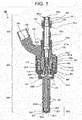
- FIG. 1 is a cross-sectional view illustrating a structure of a fuel injection device according to the first embodiment of the present invention, and is a longitudinal sectional view illustrating a cut surface parallel to a center axis 100a.
- FIG. 2 is an enlarged cross-sectional view of an electromagnetic drive unit 400 illustrated in FIG. 1 .
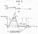
- FIG. 3 is a view illustrating operation of a movable iron core 404.
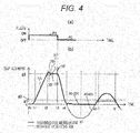
- FIGS. 3(a) and 4(a) illustrate ON/OFF states of an injection command pulse.
- FIGS. 1 is a cross-sectional view illustrating a structure of a fuel injection device according to the first embodiment of the present invention, and is a longitudinal sectional view illustrating a cut surface parallel to a center axis 100a.
- FIG. 2 is an enlarged cross-sectional view of an electromagnetic drive unit 400 illustrated in FIG. 1 .
- FIG. 3 is a view illustrating operation of a movable iron core 404.
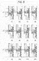
- FIG. 5 is a cross-sectional view (schematic view) illustrating operation of a movable portion.
- a recessed portion 404b of the movable iron core 404 illustrated in FIG. 2 is omitted as appropriate.
- the fuel injection device 100 includes a fuel supply unit 200, a nozzle unit 300, and an electromagnetic drive unit 400.
- the fuel supply unit 200 supplies fuel.
- a valve unit 300a for permitting or interrupting fuel flow is provided.
- the electromagnetic drive unit 400 drives the valve unit 300a.
- a fuel injection device for an internal combustion engine using gasoline as a fuel will be described as an example.
- the fuel supply unit 200, the valve unit 300a, the nozzle unit 300, and the electromagnetic drive unit 400 indicate corresponding portions with respect to the cross section illustrated in FIG. 1 and do not indicate a single component.
- the fuel injection device 100 includes the fuel supply unit 200 illustrated at the upper end side of the drawing, the nozzle unit 300 illustrated at the lower end side, and the electromagnetic drive unit 400 provided between the fuel supply unit 200 and the nozzle unit 300. That is, the fuel supply unit 200, the electromagnetic drive unit 400, and the nozzle unit 300 are disposed in this order along a direction of the center axis 100a.
- An end portion of the fuel supply unit 200 on the opposite side of the nozzle unit 300 is connected to a fuel pipe, which is not illustrated.
- An end portion of the nozzle unit 300 on the opposite side of the fuel supply unit 200 is inserted into an attachment hole (insertion hole) formed on an intake pipe, which is not illustrated, or a combustion chamber forming member (such as a cylinder block and a cylinder head) of an internal combustion engine.
- the fuel injection device 100 receives fuel from a fuel pipe through the fuel supply unit 200 and injects fuel from a distal portion of the nozzle unit 300 into the intake pipe or the combustion chamber.
- a fuel passage 101 (101a to 101f) is provided such that fuel flows from the end portion of the fuel supply unit 200 towards the distal portion of the nozzle unit 300 substantially in a direction of the center axis 100a of the fuel injection device 100.
- the end portion or the end side of the fuel supply unit 200 positioned on the opposite side of the nozzle unit 300 is referred to as a proximal end portion or a proximal end side
- the end portion or the end side of the nozzle unit 300 positioned on the opposite side of the fuel supply unit 200 is referred to as a distal portion or a distal side.
- each portion included in the fuel injection device will be described by adding "upper” or “lower” based on the vertical direction in FIG. 1 . This is merely for simplifying the description.
- a mounting form of the fuel injection device in the internal combustion engine is not limited to this vertical direction.
- the fuel supply unit 200 includes a fuel pipe 201.
- a fuel supply port 201a is provided at one end (upper end) of the fuel pipe 201, and the fuel passage 101a is formed inside the fuel pipe 201 so as to penetrate in a direction along the center axis 100a.
- the other end (lower end) of the fuel pipe 201 is bonded to one end (upper end) of the fixed iron core 401.
- An O-ring 202 and a backup ring 203 are provided on an outer peripheral side of the upper end of the fuel pipe 201.
- the O-ring 202 functions as a seal for preventing fuel leakage when the fuel supply port 201a is attached to a fuel pipe. Further, the backup ring 203 is for backing up the O-ring 202.
- the backup ring 203 may be formed by laminating a plurality of ring-shaped members. Inside the fuel supply port 201a, a filter 204 for filtering foreign matter mixed in fuel is disposed.
- the nozzle unit 300 includes a nozzle body 300b, and the valve unit 300a is formed at the distal portion (lower end) of the nozzle body 300b.
- the nozzle body 300b is a hollow cylindrical body, and a fuel passage 101f is provided upstream of the valve unit 300a. Further, a movable iron core bearing 311 is provided on a lower fuel passage 101e of the electromagnetic drive unit 400.
- a tip seal 103 for maintaining airtightness when being mounted in the internal combustion engine is provided on an outer peripheral surface of the distal portion of the nozzle body 300b.
- the valve unit 300a includes an injection hole forming member 301, a guide unit 302, and a valve body 303 provided at one end portion (distal portion in the lower end side) of the plunger rod 102.
- the injection hole forming member 301 includes a valve seat 301a which is in contact with the valve body 303 and seals fuel and a fuel injection hole 301b which injects fuel.
- the injection hole forming member 301 is inserted and fixed in a recessed inner peripheral surface 300ba formed at the distal portion of the nozzle body 300b. At this time, the outer periphery of a tip surface of the injection hole forming member 301 and the inner periphery of a tip surface of the nozzle body 300b are welded to seal fuel.
- the guide unit 302 is disposed on an inner peripheral side of the injection hole forming member 301 and forms a guide surface at an end side (lower end side) of the plunger rod 102, and the guide unit 302 guides movement of the plunger rod 102 in a direction along the center axis 100a (opening/closing valve direction).
- the electromagnetic drive unit 400 includes a fixed iron core 401, a coil 402, a housing 403, a movable iron core 404, an intermediate member 414, a plunger cap 410, a first spring member 405, a third spring member 406, and a second spring member 407.
- the fixed iron core 401 is also called a fixed core.
- the movable iron core 404 is called a movable core, a mover, or an armature.
- the fixed iron core 401 includes a fuel passage 101c in a center portion and a joining portion 401a with the fuel pipe 201.
- An outer peripheral surface 401b of the fixed iron core 401 is fitted and joined to a large diameter portion 300c (large diameter inner peripheral portion) of a cylindrical member of the nozzle body 300b, and is fitted and joined to an outer peripheral side fixed iron core 401d on an outer peripheral surface 401e having a larger diameter than the outer peripheral surface 401b.
- the coil 402 is wound around the fixed iron core 401 and the outer diameter side of the large diameter portion 300c of the cylindrical member.
- the housing 403 is provided so as to surround an outer peripheral side of the coil 402 and forms an outer periphery of the fuel injection device 100.
- An upper end side inner peripheral surface 403a of the housing 403 is connected to an outer peripheral surface 401f of the outer peripheral side fixed iron core 401d.
- the outer peripheral side fixed iron core 401d is joined to the outer peripheral surface 401e of the fixed iron core 401.
- the movable iron core 404 is disposed on a lower end surface 401g side ( FIG. 2 ) of the fixed iron core 401.
- An upper end surface 404c of the movable iron core 404 faces the lower end surface 401g of the fixed iron core 401 with a gap g3 ( FIG. 2 ) in a closed valve state.
- An outer peripheral surface of the movable iron core 404 faces an inner peripheral surface of the large diameter portion 300c of the nozzle body 300b with a slight gap formed therebetween.
- the movable iron core 404 is movably provided in a direction along the center axis 100a on the inner side of the large diameter portion 300c of the cylindrical member.
- a magnetic path is formed such that a magnetic flux circulates to the fixed iron core 401, the movable iron core 404, the housing 403, and the large diameter portion 300c of the cylindrical member.
- a magnetic attraction force generated by the magnetic flux flowing between the lower end surface 401g of the fixed iron core 401 and the upper end surface 404c of the movable iron core 404 attracts the movable iron core 404 in the fixed iron core 401 direction.
- the recessed portion 404b recessed from the upper end surface 404c side ( FIG. 2 ) to a lower end surface 404a side is formed in the center portion of the movable iron core 404.
- a fuel passage hole 404d is formed on the upper end surface 404c and a bottom surface 404b' of the recessed portion 404b as a fuel passage 101d penetrating to the lower end surface 404a side in a direction along the center axis 100a.
- a through hole 404e is formed on the bottom surface 404b' of the recessed portion 404b so as to penetrate to the lower end surface 404a side in a direction along the center axis 100a.
- the plunger rod 102 is provided so as to pass through the through hole 404e.
- a plunger cap 410 is fitted and fixed to the plunger rod 102.
- the plunger rod 102 has a thick diameter portion 102a.
- the intermediate member 414 is a cylindrical member having the recessed portion 404b functioning as a step on inner and outer peripheries.
- An inner peripheral side surface 414a comes into contact with an upper surface 102b of the thick diameter portion 102a of the plunger rod 102.
- An outer peripheral side surface 414b comes into contact with the bottom surface 404b' of the recessed portion 404b of the movable iron core 404.
- the gap g1 is provided between the lower surface 102c of the thick diameter portion 102a and the bottom surface 404b' of the recessed portion 404b of the movable iron core 404.
- the above-described gap g1 is the length obtained by subtracting the height h present between the upper surface 102b and the lower surface 102c of the thick diameter portion 102a of the plunger rod 102 from the height 414h of the recessed step of the intermediate member 414.
- a stopper portion 410c of the plunger cap 410 is disposed upstream of an upper end surface 414c of the intermediate member 414 via a gap g2.
- an upper end portion of the first spring member 405 comes into contact with a lower end surface of a spring force adjusting member 106.
- a lower end portion of the first spring member 405 comes into contact with an upper spring bearing 410a of the plunger cap 410 and energizes the plunger rod 102 downward via the plunger cap 410.
- An upper end portion of the third spring member 406 comes into contact with a lower spring bearing 410b of the plunger cap 410.
- a lower end portion of the third spring member 406 comes into contact with the upper end surface 414c of the intermediate member 414 and energizes the intermediate member 414 in a valve closing direction.
- the electromagnetic valve (fuel injection device 100) includes the first spring member 405, the third spring member 406, and the second spring member 407.
- the first spring member 405 energizes the valve body 303 in a valve closing direction.
- the third spring member 406 is attached to the stopper portion 410c or the valve body 303 and energizes the intermediate member 414 in a direction in which the preliminary stroke gap (g1) is increased.
- the second spring member 407 energizes the movable iron core 404 in a valve opening direction.
- a spring force of the first spring member 405 is larger than a spring force of the third spring member 406, and the spring force of the third spring member 406 is larger than a spring force of the second spring member 407.
- the preliminary stroke gap (g1) is formed in a valve closed state.
- the intermediate member 414 uses the third spring member 406 to energize the valve body 303 and the movable iron core 404 in the valve closing direction, and accordingly the preliminary stroke gap (g1) in the valve closed state is formed.
- the coil 402 is wound around a bobbin and assembled to the fixed iron core 401 and the outer peripheral side of the large diameter portion 300c of a cylindrical member.
- a resin material is molded around the coil 402.
- a connector 105 having a terminal 104 drawn out from the coil 402 is integrally molded with the resin material used for this mold.
- FIG. 2 is an enlarged view of the electromagnetic drive unit 400 and FIGS. 3 , 4 , and 5 which illustrates operation of a movable portion.
- FIGS. 3(a) and 4(a) are the same, and operations of the movable iron core 404 and the intermediate member 414 from t0 to t7 are the same as those in FIGS. 3(b) and 4(b) .
- the plunger rod 102 comes into contact with the valve seat 301a to close a valve, due to a force obtained by subtracting an energizing force of the third spring member 406 from an energizing force of the first spring member 405 and an energizing force of the second spring member 407, which energize the plunger rod 102 in a valve closing direction.
- This state is called a closed valve rest state.
- the movable iron core 404 is in contact with the outer peripheral side surface 414b (lower end surface) of the intermediate member 414 and is disposed in a valve closing position.
- a gap related to movable components relating to valve opening operation is formed as follows. As illustrated in FIG. 2 , the gap g2 is provided between the upper end surface 414c of the intermediate member 414 and the stopper portion 410c of the plunger cap 410. The gap g1 is included between the bottom surface 404b' of the recessed portion 404b of the movable iron core 404 and the lower surface 102c of the thick diameter portion 102a of the plunger rod 102. The relationship between g1 and g2 is configured as g2> g1.
- a magnetomotive force is generated by an electromagnet including the fixed iron core 401, the coil 402, and the housing 403. Due to this magnetomotive force, a magnetic flux circulating in a magnetic path including the fixed iron core 401 configured to surround the coil 402, the housing 403, the large diameter portion 300c (thick diameter portion) of the nozzle body 300b, and the movable iron core 404. At this time, a magnetic attractive force acts between the upper end surface 404c of the movable iron core 404 and the lower end surface 401g of the fixed iron core 401, and the movable iron core 404 and the intermediate member 414 are displaced toward the fixed iron core 401. Thereafter, as illustrated in FIG.
- the movable iron core 404 is displaced by g1 (between t0 and t1) until the movable iron core 404 comes into contact with the lower surface 102c of the thick diameter portion 102a of the plunger rod 102. At this time, the plunger rod 102 does not move.
- the plunger rod 102 receives an impact force from the movable iron core 404 and is pulled up, and the plunger rod 102 is separated from the valve seat 301a. As a result, a gap is formed in a valve seat portion, and a fuel passage is opened. The plunger rod 102 rises steeply (3A) to start valve opening by receiving an impact force. At this time, the movable iron core 404 and the intermediate member 414 perform the same operation as the plunger rod 102.
- the intermediate member 414 is provided below the third spring 406 which generates a spring force in the movable iron core 404 and the plunger rod 102.
- the intermediate member 414 is disposed by coming into contact with the bottom surface 404b' of the recessed portion 404b of the movable iron core 404 and the upper surface 102b of the thick diameter portion of the plunger rod 102. Therefore, when the movable iron core 404, the plunger rod 102, and the intermediate member 414 open a valve, and the movable iron core 404 and the fixed iron core 401 collide at the timing t2, as illustrated in FIG. 3 , the movable iron core 404 moves in a valve closing direction and the intermediate member 414 and the plunger rod 102 continue to move in a valve opening direction.
- the movable iron core 404 bounces in the valve closing direction (3D'), and the plunger rod 102 bounces in the valve opening direction (3D).
- they do not exchange mutual forces and move without exerting the spring forces which vary with the movement of each other, and the plunger rod 102 and the movable iron core 404 have small forces. Therefore, convergence of bounding of movable components becomes faster (3E), as compared with the case where a spring force that varies with the movement of each other is exerted. This effect makes it possible to stabilize a fuel injection amount.
- the gap g1 where the movable iron core 404 is displaced is formed by a difference between the height 414h of a recessed portion of the intermediate member 414 and the height h of the thick diameter portion 102a of the plunger rod 102(the height h present between the upper surface 102b and the lower surface 102c of 102a). Therefore, the gap is determined according to a component size, and adjustment in an assembling process becomes unnecessary. As a result, the assembling process can be simplified.
- the movable iron core 404 is displaced in the valve opening direction such that the second spring member causes the displacement to become zero again.
- the displacement again becomes zero at the timing t6, and the movable iron core 404 and the intermediate member 414 collide with each other.
- FIG. 4 illustrates the case where the stopper portion 410c is not included, and the intermediate member 414 is displaced further, in the valve opening direction, than the preliminary stroke gap (g1) between t7 and t8'. Then, the movable iron core 404 also moves in the direction in which the preliminary stroke gap (g1) is reduced, in accordance the displacement. As a result, the preliminary stroke gap (g1) does not exist for a certain time. In this state, when the next pulse signal is sent, the movable iron core 404 cannot open the plunger rod 102 since the preliminary stroke gap (g1) does not exist, and fuel cannot be injected.
- the electromagnetic valve (fuel injection device 100) according to the present embodiment includes the valve body 303, the movable iron core 404, and the intermediate member 414.
- the valve body 303 opens and closes a flow passage.
- the movable iron core 404 moves the valve body 303 in a valve opening direction using a magnetic attraction force.
- the intermediate member 414 forms the preliminary stroke gap (g1) between the movable iron core 404 and the valve body 303.
- the electromagnetic valve includes the stopper portion 410c which collides with the intermediate member 414 when the intermediate member 414 moves in a direction in which the preliminary stroke gap (g1) is reduced.
- the intermediate member 414 is further displaced, in the valve opening direction, than the preliminary stroke gap (g1) at the timing t7 to t8, and collides with the stopper portion 410c when the intermediate member 414 is displaced by g2. Due to this collision, the intermediate member 414 is again displaced in the valve closing direction. Consequently, a duration of the state in which the preliminary stroke gap (g1) of the movable iron core 404 does not exist can be shortened. As a result, as compared with the case illustrated in FIG. 4 , in the case illustrated in FIG. 3 in which the present embodiment is applied, return to the closed valve initial state can be made faster, and the stability of a fuel injection amount is improved.
- the movable iron core 404 and the intermediate member 414 are displaced as illustrated in FIGS. 5(10) to 5(12) .
- the intermediate member 414 collides with the stopper portion 410c when the intermediate member 414 is displaced further, in the valve opening direction, than the preliminary stroke gap (g1) and is displaced to g2. That is, in the electromagnetic valve (fuel injection device 100) according to the present embodiment, the stopper portion 410c and the intermediate member 414 are disposed via a gap (g2) larger than the preliminary stroke gap (g1).
- the stopper portion 410c is disposed at an upstream side end portion of the valve body 303. In other words, the stopper portion 410c is fixed to the valve body 303.
- the gap (g2) between the stopper portion 410c and the intermediate member 414 is determined solely by a component size, and is formed by subtracting the height from the stopper portion 410c of the plunger cap 410 to an inner peripheral side surface 410d of the plunger cap 410 and the height from the inner peripheral side surface 414a of the intermediate member 414 to the upper end surface 414c of the intermediate member 414 from the height from an upper end surface 102d of the plunger rod 102 to the upper surface 102b (upper end surface) of the thick diameter portion 102a of the plunger rod 102. Therefore, adjustment in the assembling process is not needed, and the assembling process can be simplified.
- an outer diameter 414D of the intermediate member 414 is smaller than an inner diameter 401D of the fixed iron core. Therefore, when the fuel injection device is assembled, after the gap g1 is determined by the step height 414h of the intermediate member 414 and the height h of the thick diameter portion 102a of the plunger rod 102, in a state where the spring force adjusting member 106 and the first spring member 405 are not inserted, the plunger cap 410, the plunger rod 102, the third spring member 406, and the intermediate member 414 can be integrated in advance into the fuel injection device and therefore can be easily assembled, and the gap g1 can be stably controlled.
- the outer diameter 414D of the intermediate member 414 is smaller than the inner diameter 410D of the fixed iron core 401.
- the outermost diameter of the member to be assembled in advance is smaller.
- the outermost diameter of the plunger cap 410 is larger than the outer diameter 414D (the outermost diameter) of the intermediate member 414, the outermost diameter of the plunger cap 410 needs to be smaller than the inner diameter 410D of the fixed iron core 401.
- the movable iron core 404 does not have the recessed portion 404b and is the same surface as 404c, it is possible to obtain the same operation effect as the present embodiment.
- the intermediate member 414 can be disposed further downward, the length of the plunger rod 102 in the valve opening/closing direction can be shortened, and the plunger rod 102 can be precisely formed.
- an injection amount can be stabilized even when injection is performed while the intermediate member 414 continues to be displaced after valve closing and returns to a closed valve standby state. That is, the stopper portion 410c can reduce the displacement amount of the intermediate member 414 during valve closing and reduce the period to reduce the preliminary stroke gap (g1). As a result, the fuel injection amount can be further stabilized.
- FIG. 6 A configuration of a second embodiment according to the present invention will be described with reference to FIG. 6 .
- descriptions of components denoted by the same reference signs as in the first embodiment will be omitted since there is no difference in operation effect.
- the movable iron core 404 in the closed valve state, has a recessed portion 404b2 recessed from a lower end surface side toward an upper end surface side of a center portion.
- a through hole 404f penetrating to the upper end surface side of the movable iron core 404 in a direction along a center axis 100a is formed on a bottom surface 404e2 of the recessed portion 404b2.
- a projected intermediate member 414 is inserted into the through hole 404f from a downstream side, and an upper surface 414b2 of a thick diameter portion is in contact with the recessed portion 404b2 of the movable iron core 404.
- a through hole 414e penetrating in a direction along the center axis 100a is formed in the intermediate member 414.
- a plunger rod 102 is provided so as to pass through the through hole 414e.
- an upper end surface 414f of the intermediate member 414 and a lower end surface 102g of a plunger rod thick diameter portion 102f is in contact with each other.
- the height from the upper surface 414b2 to the upper end surface 414f of the thick diameter portion of the intermediate member 414 is larger than the height from the bottom surface 404e2 of a recessed portion of the movable iron core 404 to an upper end surface 404c by g1.
- the third spring member 406 is stored in the recessed portion 404b2 of the movable iron core 404.
- One end portion of the third spring member 406 is engaged with a bottom surface 415b of the recessed portion recessed from the upper end side to the lower end surface side of the center portion of a stopper 415 stored in the recessed portion 404b2 of the movable iron core 404.
- the other end portion of the third spring member 406 is engaged with a lower end surface 414c2 of the intermediate member 414.
- the electromagnetic valve (fuel injection device 100) of the present embodiment includes the third spring member 406 which energizes the intermediate member 414 in a valve opening direction.
- the intermediate member 414 energizes a valve body 303 and the movable iron core 404, using the third spring member 406, in a valve opening direction, and a preliminary stroke gap (g1) in a closed valve state is formed.
- a lower end surface 415c of the stopper 415 and a stepped portion 300d of a nozzle body 300b are in contact with each other.
- the stopper 415 is fixed to the movable iron core 404 and forms a gap with the stepped portion 300d of the nozzle body 300b.
- stopper portion 415a of the stopper 415 is disposed with respect to the lower end surface 414c2 of the intermediate member 414 via a gap (g2) larger than the preliminary stroke gap (g1).
- the present invention is not limited to the above-described embodiments and includes various variations.
- the above-described embodiments describe the present invention in detail for clarification, and every configurations described above may not be necessarily included.
- a configuration of each embodiment can be partially replaced to a configuration of the other embodiment.
- a configuration of each embodiment can be added to the configuration of the other embodiment.
- a part of a configuration of each embodiment can be added to, deleted from, and replaced from the other configuration.
Landscapes
- Engineering & Computer Science (AREA)
- General Engineering & Computer Science (AREA)
- Mechanical Engineering (AREA)
- Chemical & Material Sciences (AREA)
- Combustion & Propulsion (AREA)
- Physics & Mathematics (AREA)
- Electromagnetism (AREA)
- Power Engineering (AREA)
- Fuel-Injection Apparatus (AREA)
- Magnetically Actuated Valves (AREA)
Abstract
Description
- The present invention relates to an electromagnetic valve.
- In a fuel injection nozzle, a structure is known in which an intermediate member slidable on both a movable iron core and a valve body and forming a gap in a displacement direction between the movable iron core and the valve body in a closed valve state (refer to, for example, PTL 1). According to such a structure, since the movable iron core collides with the valve body when a valve opens, it is possible to shorten a traveling time by a distance necessary for opening an injection hole and to relatively move the movable iron core and the valve after the valve is opened or closed. As a result, controllability of an injection amount is improved.
- PTL 1:
JP 2011-137442 A - In a fuel injection device, promotion of finer atomization of spray and stabilization of an injection amount are required. Finer spray atomization is deteriorated as a result of a reduction of fuel flow rate in a low lift period at the beginning of opening of a valve body. The injection amount stabilization is deteriorated as a result of slow convergence of valve operation after valve opening. Therefore, it is necessary for the fuel injection device to rapidly converge operation of the valve body after valve opening as well as steeply starting opening of the valve.
- In
PTL 1, by providing a gap in a displacement direction on a movable iron core and a valve body, only the movable iron core is operated before starting energization, an impact force at collision is applied to the valve body during valve opening, and a low lift period is shortened. Further, by providing an intermediate member between the movable iron core and the valve body, relative movement between the valve body and the movable iron core is allowed, and an injection amount is stabilized. - However, there is a problem that, when injection is performed while the intermediate member continues to be displaced after valve closing and returns to a closed valve standby state, a gap in the displacement direction becomes small and an injection amount (valve opening behavior) is not stabilized.
- Accordingly, an object of the present invention is to provide an electromagnetic valve capable of stabilizing an injection amount even when injection is performed while an intermediate member continues to be displaced after valve closing and returns to a closed valve standby state.
- To achieve the above-described object, the present invention provides an electromagnetic valve including a valve body, a movable iron core, an intermediate member, and a stopper portion. The valve body opens and closes a flow path. The movable iron core moves the valve body in a valve opening direction using a magnetic attraction force. The intermediate member forms a preliminary stroke gap (g1) between the movable iron core and the valve body in a closed valve state. The stopper portion collides with the intermediate member when the intermediate member moves in a direction in which the preliminary stroke gap (g1) is reduced.
- According to the present invention, an electromagnetic valve can stabilize an injection amount even when injection is performed while an intermediate member continues to be displaced after valve closing and returns to a closed valve standby state. Issues, configurations, and effects other than the above are clarified by descriptions of the following embodiment.
-
- [
FIG. 1] FIG. 1 is a cross-sectional view illustrating a structure of a fuel injection device according to a first embodiment of the present invention, and is a longitudinal cross-sectional view sowing a cut surface parallel to a center axis. - [
FIG. 2] FIG. 2 is an enlarged cross-sectional view of an electromagnetic drive unit of the fuel injection device illustrated inFIG. 1 . - [
FIG. 3] FIG. 3 is a view illustrating operation of a movable portion in the case where a stopper portion is set in response to an injection command pulse, according to the first embodiment of the present invention. - [
FIG. 4] FIG. 4 is a view illustrating operation of the movable portion in the case where the stopper portion is not set in response to the injection command pulse, according to the first embodiment of the present invention. - [
FIG. 5] FIG. 5 is a cross-sectional view (schematic view) illustrating operation of the movable portion according to the first embodiment of the present invention. - [
FIG. 6] FIG. 6 is a cross-sectional view illustrating a structure of a fuel injection device according to a second embodiment of the present invention, and is an enlarged cross-sectional view of an electromagnetic drive unit. - Hereinafter, configurations and operation effects of a fuel injection valve (electromagnetic valve) according to first and second embodiments of the present invention will be described with reference to the drawings.
- A configuration of a
fuel injection device 100 according to a first embodiment of the present invention will be described with reference toFIGS. 1 to 5 .FIG. 1 is a cross-sectional view illustrating a structure of a fuel injection device according to the first embodiment of the present invention, and is a longitudinal sectional view illustrating a cut surface parallel to acenter axis 100a.FIG. 2 is an enlarged cross-sectional view of anelectromagnetic drive unit 400 illustrated inFIG. 1 .FIG. 3 is a view illustrating operation of amovable iron core 404.FIGS. 3(a) and4(a) illustrate ON/OFF states of an injection command pulse.FIGS. 3(b) and4(b) illustrate displacement of themovable iron core 404 and anintermediate member 414 when a closed valve state of aplunger rod 102 is set todisplacement 0. Operations from t0 to t7 of themovable iron core 404 and theintermediate member 414 illustrated inFIGS. 3(b) and4(b) are the same.FIG. 5 is a cross-sectional view (schematic view) illustrating operation of a movable portion. InFIG. 5 , such as arecessed portion 404b of themovable iron core 404 illustrated inFIG. 2 is omitted as appropriate. - The
fuel injection device 100 includes afuel supply unit 200, anozzle unit 300, and anelectromagnetic drive unit 400. Thefuel supply unit 200 supplies fuel. At a tip of thenozzle unit 300, avalve unit 300a for permitting or interrupting fuel flow is provided. Theelectromagnetic drive unit 400 drives thevalve unit 300a. In the present embodiment, a fuel injection device for an internal combustion engine using gasoline as a fuel will be described as an example. Thefuel supply unit 200, thevalve unit 300a, thenozzle unit 300, and theelectromagnetic drive unit 400 indicate corresponding portions with respect to the cross section illustrated inFIG. 1 and do not indicate a single component. - The
fuel injection device 100 according to the present embodiment includes thefuel supply unit 200 illustrated at the upper end side of the drawing, thenozzle unit 300 illustrated at the lower end side, and theelectromagnetic drive unit 400 provided between thefuel supply unit 200 and thenozzle unit 300. That is, thefuel supply unit 200, theelectromagnetic drive unit 400, and thenozzle unit 300 are disposed in this order along a direction of thecenter axis 100a. - An end portion of the
fuel supply unit 200 on the opposite side of thenozzle unit 300 is connected to a fuel pipe, which is not illustrated. An end portion of thenozzle unit 300 on the opposite side of thefuel supply unit 200 is inserted into an attachment hole (insertion hole) formed on an intake pipe, which is not illustrated, or a combustion chamber forming member (such as a cylinder block and a cylinder head) of an internal combustion engine. Thefuel injection device 100 receives fuel from a fuel pipe through thefuel supply unit 200 and injects fuel from a distal portion of thenozzle unit 300 into the intake pipe or the combustion chamber. Inside thefuel injection device 100, a fuel passage 101 (101a to 101f) is provided such that fuel flows from the end portion of thefuel supply unit 200 towards the distal portion of thenozzle unit 300 substantially in a direction of thecenter axis 100a of thefuel injection device 100. - In the following description, regarding both end portions in the direction along the
center axis 100a of thefuel injection device 100, the end portion or the end side of thefuel supply unit 200 positioned on the opposite side of thenozzle unit 300 is referred to as a proximal end portion or a proximal end side, and the end portion or the end side of thenozzle unit 300 positioned on the opposite side of thefuel supply unit 200 is referred to as a distal portion or a distal side. Further, each portion included in the fuel injection device will be described by adding "upper" or "lower" based on the vertical direction inFIG. 1 . This is merely for simplifying the description. A mounting form of the fuel injection device in the internal combustion engine is not limited to this vertical direction. - Hereinafter, configurations of the
fuel supply unit 200, theelectromagnetic drive unit 400, and thenozzle unit 300 will be described in detail. - The
fuel supply unit 200 includes afuel pipe 201. Afuel supply port 201a is provided at one end (upper end) of thefuel pipe 201, and thefuel passage 101a is formed inside thefuel pipe 201 so as to penetrate in a direction along thecenter axis 100a. The other end (lower end) of thefuel pipe 201 is bonded to one end (upper end) of the fixediron core 401. - An O-
ring 202 and abackup ring 203 are provided on an outer peripheral side of the upper end of thefuel pipe 201. - The O-
ring 202 functions as a seal for preventing fuel leakage when thefuel supply port 201a is attached to a fuel pipe. Further, thebackup ring 203 is for backing up the O-ring 202. Thebackup ring 203 may be formed by laminating a plurality of ring-shaped members. Inside thefuel supply port 201a, afilter 204 for filtering foreign matter mixed in fuel is disposed. - The
nozzle unit 300 includes anozzle body 300b, and thevalve unit 300a is formed at the distal portion (lower end) of thenozzle body 300b. Thenozzle body 300b is a hollow cylindrical body, and afuel passage 101f is provided upstream of thevalve unit 300a. Further, a movable iron core bearing 311 is provided on alower fuel passage 101e of theelectromagnetic drive unit 400. Atip seal 103 for maintaining airtightness when being mounted in the internal combustion engine is provided on an outer peripheral surface of the distal portion of thenozzle body 300b. - The
valve unit 300a includes an injectionhole forming member 301, aguide unit 302, and avalve body 303 provided at one end portion (distal portion in the lower end side) of theplunger rod 102. - The injection
hole forming member 301 includes avalve seat 301a which is in contact with thevalve body 303 and seals fuel and afuel injection hole 301b which injects fuel. The injectionhole forming member 301 is inserted and fixed in a recessed inner peripheral surface 300ba formed at the distal portion of thenozzle body 300b. At this time, the outer periphery of a tip surface of the injectionhole forming member 301 and the inner periphery of a tip surface of thenozzle body 300b are welded to seal fuel. - The
guide unit 302 is disposed on an inner peripheral side of the injectionhole forming member 301 and forms a guide surface at an end side (lower end side) of theplunger rod 102, and theguide unit 302 guides movement of theplunger rod 102 in a direction along the center axis 100a (opening/closing valve direction). - The
electromagnetic drive unit 400 includes a fixediron core 401, acoil 402, ahousing 403, amovable iron core 404, anintermediate member 414, aplunger cap 410, afirst spring member 405, athird spring member 406, and asecond spring member 407. The fixediron core 401 is also called a fixed core. Themovable iron core 404 is called a movable core, a mover, or an armature. - The fixed
iron core 401 includes afuel passage 101c in a center portion and a joiningportion 401a with thefuel pipe 201. An outerperipheral surface 401b of the fixediron core 401 is fitted and joined to alarge diameter portion 300c (large diameter inner peripheral portion) of a cylindrical member of thenozzle body 300b, and is fitted and joined to an outer peripheral side fixediron core 401d on an outerperipheral surface 401e having a larger diameter than the outerperipheral surface 401b. Thecoil 402 is wound around the fixediron core 401 and the outer diameter side of thelarge diameter portion 300c of the cylindrical member. - The
housing 403 is provided so as to surround an outer peripheral side of thecoil 402 and forms an outer periphery of thefuel injection device 100. An upper end side innerperipheral surface 403a of thehousing 403 is connected to an outerperipheral surface 401f of the outer peripheral side fixediron core 401d. Here, the outer peripheral side fixediron core 401d is joined to the outerperipheral surface 401e of the fixediron core 401. - The
movable iron core 404 is disposed on alower end surface 401g side (FIG. 2 ) of the fixediron core 401. Anupper end surface 404c of themovable iron core 404 faces thelower end surface 401g of the fixediron core 401 with a gap g3 (FIG. 2 ) in a closed valve state. An outer peripheral surface of themovable iron core 404 faces an inner peripheral surface of thelarge diameter portion 300c of thenozzle body 300b with a slight gap formed therebetween. Themovable iron core 404 is movably provided in a direction along thecenter axis 100a on the inner side of thelarge diameter portion 300c of the cylindrical member. - A magnetic path is formed such that a magnetic flux circulates to the fixed
iron core 401, themovable iron core 404, thehousing 403, and thelarge diameter portion 300c of the cylindrical member. A magnetic attraction force generated by the magnetic flux flowing between thelower end surface 401g of the fixediron core 401 and theupper end surface 404c of themovable iron core 404 attracts themovable iron core 404 in the fixediron core 401 direction. - The recessed
portion 404b recessed from theupper end surface 404c side (FIG. 2 ) to alower end surface 404a side is formed in the center portion of themovable iron core 404. Afuel passage hole 404d is formed on theupper end surface 404c and abottom surface 404b' of the recessedportion 404b as afuel passage 101d penetrating to thelower end surface 404a side in a direction along thecenter axis 100a. A throughhole 404e is formed on thebottom surface 404b' of the recessedportion 404b so as to penetrate to thelower end surface 404a side in a direction along thecenter axis 100a. Theplunger rod 102 is provided so as to pass through the throughhole 404e. Aplunger cap 410 is fitted and fixed to theplunger rod 102. Theplunger rod 102 has athick diameter portion 102a. - The
intermediate member 414 is a cylindrical member having the recessedportion 404b functioning as a step on inner and outer peripheries. An innerperipheral side surface 414a comes into contact with anupper surface 102b of thethick diameter portion 102a of theplunger rod 102. An outerperipheral side surface 414b (lower end surface) comes into contact with thebottom surface 404b' of the recessedportion 404b of themovable iron core 404. The gap g1 is provided between thelower surface 102c of thethick diameter portion 102a and thebottom surface 404b' of the recessedportion 404b of themovable iron core 404. The above-described gap g1 is the length obtained by subtracting the height h present between theupper surface 102b and thelower surface 102c of thethick diameter portion 102a of theplunger rod 102 from theheight 414h of the recessed step of theintermediate member 414. - A
stopper portion 410c of theplunger cap 410 is disposed upstream of anupper end surface 414c of theintermediate member 414 via a gap g2. - As illustrated in
FIG. 1 , an upper end portion of thefirst spring member 405 comes into contact with a lower end surface of a springforce adjusting member 106. As illustrated inFIG. 2 , a lower end portion of thefirst spring member 405 comes into contact with an upper spring bearing 410a of theplunger cap 410 and energizes theplunger rod 102 downward via theplunger cap 410. An upper end portion of thethird spring member 406 comes into contact with alower spring bearing 410b of theplunger cap 410. A lower end portion of thethird spring member 406 comes into contact with theupper end surface 414c of theintermediate member 414 and energizes theintermediate member 414 in a valve closing direction. - An upper end portion of the
second spring 407 comes into contact with thelower end surface 404a of themovable iron core 404. The lower end portion of thesecond spring 407 comes into contact with a steppedportion 300d of thenozzle body 300b to energize themovable iron core 404 in a valve opening direction. That is, the electromagnetic valve (fuel injection device 100) according to the present embodiment includes thefirst spring member 405, thethird spring member 406, and thesecond spring member 407. Thefirst spring member 405 energizes thevalve body 303 in a valve closing direction. Thethird spring member 406 is attached to thestopper portion 410c or thevalve body 303 and energizes theintermediate member 414 in a direction in which the preliminary stroke gap (g1) is increased. Thesecond spring member 407 energizes themovable iron core 404 in a valve opening direction. A spring force of thefirst spring member 405 is larger than a spring force of thethird spring member 406, and the spring force of thethird spring member 406 is larger than a spring force of thesecond spring member 407. As a result, the preliminary stroke gap (g1) is formed in a valve closed state. - In other words, the
intermediate member 414 uses thethird spring member 406 to energize thevalve body 303 and themovable iron core 404 in the valve closing direction, and accordingly the preliminary stroke gap (g1) in the valve closed state is formed. - As illustrated in
FIG. 1 , thecoil 402 is wound around a bobbin and assembled to the fixediron core 401 and the outer peripheral side of thelarge diameter portion 300c of a cylindrical member. A resin material is molded around thecoil 402. Aconnector 105 having a terminal 104 drawn out from thecoil 402 is integrally molded with the resin material used for this mold. - Next, operation of the
fuel injection device 100 in this embodiment and characteristics of the present invention will be described. The operation and the characteristics will be described mainly with reference toFIG. 2 which is an enlarged view of theelectromagnetic drive unit 400 andFIGS. 3 ,4 , and5 which illustrates operation of a movable portion.FIGS. 3(a) and4(a) are the same, and operations of themovable iron core 404 and theintermediate member 414 from t0 to t7 are the same as those inFIGS. 3(b) and4(b) . - In a closed valve state in which the
coil 402 is not energized, theplunger rod 102 comes into contact with thevalve seat 301a to close a valve, due to a force obtained by subtracting an energizing force of thethird spring member 406 from an energizing force of thefirst spring member 405 and an energizing force of thesecond spring member 407, which energize theplunger rod 102 in a valve closing direction. This state is called a closed valve rest state. At this time, themovable iron core 404 is in contact with the outerperipheral side surface 414b (lower end surface) of theintermediate member 414 and is disposed in a valve closing position. - In the closed valve state of the fuel injection device according to the present embodiment, a gap related to movable components relating to valve opening operation is formed as follows. As illustrated in
FIG. 2 , the gap g2 is provided between theupper end surface 414c of theintermediate member 414 and thestopper portion 410c of theplunger cap 410. The gap g1 is included between thebottom surface 404b' of the recessedportion 404b of themovable iron core 404 and thelower surface 102c of thethick diameter portion 102a of theplunger rod 102. The relationship between g1 and g2 is configured as g2> g1. - After energizing the coil 402 (P1), a magnetomotive force is generated by an electromagnet including the fixed
iron core 401, thecoil 402, and thehousing 403. Due to this magnetomotive force, a magnetic flux circulating in a magnetic path including the fixediron core 401 configured to surround thecoil 402, thehousing 403, thelarge diameter portion 300c (thick diameter portion) of thenozzle body 300b, and themovable iron core 404. At this time, a magnetic attractive force acts between theupper end surface 404c of themovable iron core 404 and thelower end surface 401g of the fixediron core 401, and themovable iron core 404 and theintermediate member 414 are displaced toward the fixediron core 401. Thereafter, as illustrated inFIG. 3 , themovable iron core 404 is displaced by g1 (between t0 and t1) until themovable iron core 404 comes into contact with thelower surface 102c of thethick diameter portion 102a of theplunger rod 102. At this time, theplunger rod 102 does not move. - That is, the
movable iron core 404 and theintermediate member 414 are displaced as illustrated inFIGS. 5(1) and 5(2) . - Then, as illustrated in
FIG. 3 , when themovable iron core 404 is in contact with thelower surface 102c of thethick diameter portion 102a of theplunger rod 102 at the timing of t1, theplunger rod 102 receives an impact force from themovable iron core 404 and is pulled up, and theplunger rod 102 is separated from thevalve seat 301a. As a result, a gap is formed in a valve seat portion, and a fuel passage is opened. Theplunger rod 102 rises steeply (3A) to start valve opening by receiving an impact force. At this time, themovable iron core 404 and theintermediate member 414 perform the same operation as theplunger rod 102. - Then, when the
plunger rod 102 is displaced by g3 and theupper end surface 404c of themovable iron core 404 comes into contact with thelower end surface 401g of the fixediron core 401 at the timing t2, theintermediate member 414 is displaced upward (3B), themovable iron core 404 is displaced downward (3B'), and themovable iron core 404 and the fixediron core 401 again collide with each other (3C: contacted). After that, themovable iron core 404 and the fixediron core 401 are separated again, and theplunger rod 102 moves upward (3D), and themovable iron core 404 moves downward (3D'), and then those are stabilized to be displaced by g3 (3E). - That is, the
movable iron core 404 and theintermediate member 414 are displaced as illustrated inFIGS. 5(3) to 5(5) . - In the present embodiment, as illustrated in
FIG. 2 , theintermediate member 414 is provided below thethird spring 406 which generates a spring force in themovable iron core 404 and theplunger rod 102. Theintermediate member 414 is disposed by coming into contact with thebottom surface 404b' of the recessedportion 404b of themovable iron core 404 and theupper surface 102b of the thick diameter portion of theplunger rod 102. Therefore, when themovable iron core 404, theplunger rod 102, and theintermediate member 414 open a valve, and themovable iron core 404 and the fixediron core 401 collide at the timing t2, as illustrated inFIG. 3 , themovable iron core 404 moves in a valve closing direction and theintermediate member 414 and theplunger rod 102 continue to move in a valve opening direction. - In this state, no spring force acting between the
movable iron core 404 and theplunger rod 102 is generated, and the spring force is separated. Therefore, the spring force which varies with the movement of themovable iron core 404 is not transmitted to theplunger rod 102. On the contrary, the spring force which varies with the movement of theplunger rod 102 is not transmitted to themovable iron core 404. The forces mutually independently vibrate with collision (3B and 3B'). - Further, when colliding again (3C), the
movable iron core 404 bounces in the valve closing direction (3D'), and theplunger rod 102 bounces in the valve opening direction (3D). However, they do not exchange mutual forces and move without exerting the spring forces which vary with the movement of each other, and theplunger rod 102 and themovable iron core 404 have small forces. Therefore, convergence of bounding of movable components becomes faster (3E), as compared with the case where a spring force that varies with the movement of each other is exerted. This effect makes it possible to stabilize a fuel injection amount. - Further, in a valve closed state, the gap g1 where the
movable iron core 404 is displaced is formed by a difference between theheight 414h of a recessed portion of theintermediate member 414 and the height h of thethick diameter portion 102a of the plunger rod 102(the height h present between theupper surface 102b and thelower surface 102c of 102a). Therefore, the gap is determined according to a component size, and adjustment in an assembling process becomes unnecessary. As a result, the assembling process can be simplified. - When energization to the
coil 402 is interrupted (P2) at the timing t3, a magnetic force starts to disappear and valve closing operation is performed by an energizing force of a spring in a valve closing direction. After displacement of theplunger rod 102 becomes zero at the timing t4, theplunger rod 102 comes into contact with thevalve seat 301a, and a valve is completely closed. Further, since theintermediate member 414 is in contact with theupper surface 102b of thethick diameter portion 102a of theplunger rod 102, the displacement does not become smaller than zero. On the other hand, themovable iron core 404 is further displaced in the valve closing direction even after the displacement of theintermediate member 414 becomes zero at the timing t4. After themovable iron core 404 is most displaced in the valve closing direction at the timing t5, themovable iron core 404 is displaced in the valve opening direction such that the second spring member causes the displacement to become zero again. The displacement again becomes zero at the timing t6, and themovable iron core 404 and theintermediate member 414 collide with each other. - That is, the
movable iron core 404 and theintermediate member 414 are displaced as illustrated inFIGS. 5(5) to 5(9) . - At the timing t7, the
movable iron core 404 collides with thelower surface 102c of thethick diameter portion 102a of theplunger rod 102.FIG. 4 illustrates the case where thestopper portion 410c is not included, and theintermediate member 414 is displaced further, in the valve opening direction, than the preliminary stroke gap (g1) between t7 and t8'. Then, themovable iron core 404 also moves in the direction in which the preliminary stroke gap (g1) is reduced, in accordance the displacement. As a result, the preliminary stroke gap (g1) does not exist for a certain time. In this state, when the next pulse signal is sent, themovable iron core 404 cannot open theplunger rod 102 since the preliminary stroke gap (g1) does not exist, and fuel cannot be injected. - Therefore, in the present embodiment, to solve such a problem, a characteristic upper spring bearing 410a (
stopper portion 410c) is provided. That is, the electromagnetic valve (fuel injection device 100) according to the present embodiment includes thevalve body 303, themovable iron core 404, and theintermediate member 414. Thevalve body 303 opens and closes a flow passage. Themovable iron core 404 moves thevalve body 303 in a valve opening direction using a magnetic attraction force. Theintermediate member 414 forms the preliminary stroke gap (g1) between themovable iron core 404 and thevalve body 303. Further, the electromagnetic valve includes thestopper portion 410c which collides with theintermediate member 414 when theintermediate member 414 moves in a direction in which the preliminary stroke gap (g1) is reduced. - In this case, as illustrated in
FIG. 3 , theintermediate member 414 is further displaced, in the valve opening direction, than the preliminary stroke gap (g1) at the timing t7 to t8, and collides with thestopper portion 410c when theintermediate member 414 is displaced by g2. Due to this collision, theintermediate member 414 is again displaced in the valve closing direction. Consequently, a duration of the state in which the preliminary stroke gap (g1) of themovable iron core 404 does not exist can be shortened. As a result, as compared with the case illustrated inFIG. 4 , in the case illustrated inFIG. 3 in which the present embodiment is applied, return to the closed valve initial state can be made faster, and the stability of a fuel injection amount is improved. - That is, the
movable iron core 404 and theintermediate member 414 are displaced as illustrated inFIGS. 5(10) to 5(12) . - Again, as illustrated in
FIG. 3 , during the valve closing operation, theintermediate member 414 collides with thestopper portion 410c when theintermediate member 414 is displaced further, in the valve opening direction, than the preliminary stroke gap (g1) and is displaced to g2. That is, in the electromagnetic valve (fuel injection device 100) according to the present embodiment, thestopper portion 410c and theintermediate member 414 are disposed via a gap (g2) larger than the preliminary stroke gap (g1). Thestopper portion 410c is disposed at an upstream side end portion of thevalve body 303. In other words, thestopper portion 410c is fixed to thevalve body 303. - Accordingly, only the case where the
intermediate member 414 is displaced in the valve opening direction can be limited. - Further, in the present embodiment, the gap (g2) between the
stopper portion 410c and theintermediate member 414 is determined solely by a component size, and is formed by subtracting the height from thestopper portion 410c of theplunger cap 410 to an innerperipheral side surface 410d of theplunger cap 410 and the height from the innerperipheral side surface 414a of theintermediate member 414 to theupper end surface 414c of theintermediate member 414 from the height from anupper end surface 102d of theplunger rod 102 to theupper surface 102b (upper end surface) of thethick diameter portion 102a of theplunger rod 102. Therefore, adjustment in the assembling process is not needed, and the assembling process can be simplified. - Further, in the configuration of the present embodiment, an
outer diameter 414D of theintermediate member 414 is smaller than an inner diameter 401D of the fixed iron core. Therefore, when the fuel injection device is assembled, after the gap g1 is determined by thestep height 414h of theintermediate member 414 and the height h of thethick diameter portion 102a of theplunger rod 102, in a state where the springforce adjusting member 106 and thefirst spring member 405 are not inserted, theplunger cap 410, theplunger rod 102, thethird spring member 406, and theintermediate member 414 can be integrated in advance into the fuel injection device and therefore can be easily assembled, and the gap g1 can be stably controlled. In the present embodiment, theouter diameter 414D of theintermediate member 414 is smaller than theinner diameter 410D of the fixediron core 401. However, what is required is that the outermost diameter of the member to be assembled in advance is smaller. In the case where the outermost diameter of theplunger cap 410 is larger than theouter diameter 414D (the outermost diameter) of theintermediate member 414, the outermost diameter of theplunger cap 410 needs to be smaller than theinner diameter 410D of the fixediron core 401. - In the present embodiment, even if the
movable iron core 404 does not have the recessedportion 404b and is the same surface as 404c, it is possible to obtain the same operation effect as the present embodiment. By providing the recessedportion 404b of themovable iron core 404, theintermediate member 414 can be disposed further downward, the length of theplunger rod 102 in the valve opening/closing direction can be shortened, and theplunger rod 102 can be precisely formed. - As described above, according to the present embodiment, an injection amount can be stabilized even when injection is performed while the
intermediate member 414 continues to be displaced after valve closing and returns to a closed valve standby state. That is, thestopper portion 410c can reduce the displacement amount of theintermediate member 414 during valve closing and reduce the period to reduce the preliminary stroke gap (g1). As a result, the fuel injection amount can be further stabilized. - A configuration of a second embodiment according to the present invention will be described with reference to
FIG. 6 . In the drawing, descriptions of components denoted by the same reference signs as in the first embodiment will be omitted since there is no difference in operation effect. - In the present embodiment, in the closed valve state, the
movable iron core 404 has a recessed portion 404b2 recessed from a lower end surface side toward an upper end surface side of a center portion. A throughhole 404f penetrating to the upper end surface side of themovable iron core 404 in a direction along acenter axis 100a is formed on a bottom surface 404e2 of the recessed portion 404b2. A projectedintermediate member 414 is inserted into the throughhole 404f from a downstream side, and an upper surface 414b2 of a thick diameter portion is in contact with the recessed portion 404b2 of themovable iron core 404. Further, a throughhole 414e penetrating in a direction along thecenter axis 100a is formed in theintermediate member 414. Aplunger rod 102 is provided so as to pass through the throughhole 414e. In the closed valve state, an upper end surface 414f of theintermediate member 414 and alower end surface 102g of a plunger rodthick diameter portion 102f is in contact with each other. - The height from the upper surface 414b2 to the upper end surface 414f of the thick diameter portion of the
intermediate member 414 is larger than the height from the bottom surface 404e2 of a recessed portion of themovable iron core 404 to anupper end surface 404c by g1. - Here, a configuration of a
third spring member 406 will also be described. - The
third spring member 406 is stored in the recessed portion 404b2 of themovable iron core 404. One end portion of thethird spring member 406 is engaged with abottom surface 415b of the recessed portion recessed from the upper end side to the lower end surface side of the center portion of astopper 415 stored in the recessed portion 404b2 of themovable iron core 404. The other end portion of thethird spring member 406 is engaged with a lower end surface 414c2 of theintermediate member 414. That is, the electromagnetic valve (fuel injection device 100) of the present embodiment includes thethird spring member 406 which energizes theintermediate member 414 in a valve opening direction. Theintermediate member 414 energizes avalve body 303 and themovable iron core 404, using thethird spring member 406, in a valve opening direction, and a preliminary stroke gap (g1) in a closed valve state is formed. - In the present embodiment, a
lower end surface 415c of thestopper 415 and a steppedportion 300d of anozzle body 300b are in contact with each other. However, thestopper 415 is fixed to themovable iron core 404 and forms a gap with the steppedportion 300d of thenozzle body 300b. - Further, the
stopper portion 415a of thestopper 415 is disposed with respect to the lower end surface 414c2 of theintermediate member 414 via a gap (g2) larger than the preliminary stroke gap (g1). - Further, in the present embodiment, it is possible to reduce the time during which the preliminary stroke gap g1 collides with the
stopper portion 415a while theintermediate member 414 is displaced to the downstream side after the opening/closing valve operation and to further stabilize the injection amount. - The present invention is not limited to the above-described embodiments and includes various variations. For example, the above-described embodiments describe the present invention in detail for clarification, and every configurations described above may not be necessarily included. Further, a configuration of each embodiment can be partially replaced to a configuration of the other embodiment. Furthermore, a configuration of each embodiment can be added to the configuration of the other embodiment. Further, a part of a configuration of each embodiment can be added to, deleted from, and replaced from the other configuration.
-
- 100
- fuel injection device
- 101
- fuel passage
- 102
- plunger rod
- 200
- fuel supply unit
- 300
- nozzle unit
- 301a
- valve seat
- 301b
- fuel injection hole
- 311
- movable iron core bearing
- 400
- electromagnetic drive unit
- 401
- fixed iron core
- 402
- coil
- 403
- housing
- 404
- movable iron core
- 405
- first spring member
- 406
- third spring member
- 407
- second spring member
- 414
- intermediate member
Claims (10)
- An electromagnetic valve, comprising:a valve body configured to open and close a flow path;a movable iron core configured to move the valve body in a valve opening direction using a magnetic attraction force;an intermediate member configured to form a preliminary stroke gap (g1) between the movable iron core and the valve body in a closed valve state; anda stopper portion which collides with the intermediate member when the intermediate member moves in a direction in which the preliminary stroke gap (g1) is reduced.
- The electromagnetic valve according to claim 1, wherein the stopper portion and the intermediate member are disposed via a gap (g2) larger than the preliminary stroke gap (g1).
- The electromagnetic valve according to claim 1, wherein the stopper portion is disposed at an upstream end portion of the valve body.
- The electromagnetic valve according to claim 1, wherein the stopper portion is fixed to the valve body.
- The electromagnetic valve according to claim 1, further comprising:a first spring member configured to energize the valve body in a valve closing direction; anda third spring member attached to the stopper portion or the valve body and configured to energize the intermediate member in a direction in which the preliminary stroke gap (g1) is increased,wherein, a spring force of the first spring member is larger than a spring force of the third spring member.
- The electromagnetic valve according to claim 1, further comprising:the first spring member configured to energize the valve body in a valve closing direction;the third spring member attached to the stopper portion or the valve body and configured to energize the intermediate member in a direction in which the preliminary stroke gap (g1) is increased; anda second spring member configured to energize the movable iron core in a valve opening direction,wherein a spring force of the first spring member is larger than a spring force of the third spring member, and the spring force of the third spring member is larger than a spring force of the second spring member.
- The electromagnetic valve according to claim 1, further comprising the third spring member configured to energize the intermediate member in a valve closing direction,
wherein when the intermediate member energizes the valve body and the movable iron core in a valve closing direction using the third spring member, the preliminary stroke gap (g1) in the closed valve state is formed. - The electromagnetic valve according to claim 7, wherein the stopper portion is disposed upstream of the intermediate member via a gap (g2).
- The electromagnetic valve according to claim 1, further comprising the third spring member configured to energize the intermediate member in a valve opening direction,
wherein when the intermediate member energizes the valve body and the movable iron core in a valve opening direction using the third spring member, the preliminary stroke gap (g1) in the closed valve state is formed. - The electromagnetic valve according to claim 9, wherein the stopper portion is disposed downstream of the intermediate member via the gap (g2).
Applications Claiming Priority (2)
| Application Number | Priority Date | Filing Date | Title |
|---|---|---|---|
| JP2015165357 | 2015-08-25 | ||
| PCT/JP2016/071661 WO2017033645A1 (en) | 2015-08-25 | 2016-07-25 | Solenoid valve |
Publications (3)
| Publication Number | Publication Date |
|---|---|
| EP3343079A1 true EP3343079A1 (en) | 2018-07-04 |
| EP3343079A4 EP3343079A4 (en) | 2019-03-27 |
| EP3343079B1 EP3343079B1 (en) | 2021-03-10 |
Family
ID=58099949
Family Applications (1)
| Application Number | Title | Priority Date | Filing Date |
|---|---|---|---|
| EP16838992.2A Not-in-force EP3343079B1 (en) | 2015-08-25 | 2016-07-25 | Solenoid valve |
Country Status (5)
| Country | Link |
|---|---|
| US (1) | US10690097B2 (en) |
| EP (1) | EP3343079B1 (en) |
| JP (1) | JP6563020B2 (en) |
| CN (1) | CN107923548B (en) |
| WO (1) | WO2017033645A1 (en) |
Cited By (1)
| Publication number | Priority date | Publication date | Assignee | Title |
|---|---|---|---|---|
| WO2020025354A1 (en) * | 2018-08-01 | 2020-02-06 | Delphi Automotive Systems Luxembourg Sa | Fuel injector |
Families Citing this family (3)
| Publication number | Priority date | Publication date | Assignee | Title |
|---|---|---|---|---|
| SE540880C2 (en) * | 2016-09-28 | 2018-12-11 | Freevalve Ab | Multi-way valve as well as actuator comprising such a multi-way valve |
| CN111344483B (en) * | 2017-11-22 | 2022-03-08 | 日立安斯泰莫株式会社 | fuel injection device |
| US11721465B2 (en) | 2020-04-24 | 2023-08-08 | Rain Bird Corporation | Solenoid apparatus and methods of assembly |
Family Cites Families (13)
| Publication number | Priority date | Publication date | Assignee | Title |
|---|---|---|---|---|
| JPS6411484U (en) * | 1987-07-10 | 1989-01-20 | ||
| JP3479353B2 (en) | 1994-10-17 | 2003-12-15 | 株式会社ケーヒン | Exhaust gas recirculation valve |
| DE10039077A1 (en) * | 2000-08-10 | 2002-02-21 | Bosch Gmbh Robert | Fuel injection valve esp. of IC engines with solenoid coil and armature and return spring also valve needle for operating valve closing body which together with valve seat surface forms sealed seat |
| DE10051549A1 (en) * | 2000-10-18 | 2002-04-25 | Bosch Gmbh Robert | Solenoid valve to control fuel injection valve of IC engines has armature pin with part sliding between fixed and moveable stop |
| DE10136808A1 (en) * | 2001-07-27 | 2003-02-13 | Bosch Gmbh Robert | IC engine fuel injection valve, has magnetic coils and two cooperating armatures with respective positioning springs between latter and valve needle flanges |
| JP5218487B2 (en) * | 2009-12-04 | 2013-06-26 | 株式会社デンソー | Fuel injection valve |
| JP2011190798A (en) * | 2010-02-17 | 2011-09-29 | Denso Corp | Fuel injection valve |
| JP5768536B2 (en) * | 2010-10-05 | 2015-08-26 | 株式会社デンソー | Fuel injection valve |
| JP6139191B2 (en) * | 2013-03-14 | 2017-05-31 | 日立オートモティブシステムズ株式会社 | Electromagnetic fuel injection valve |
| JP6087210B2 (en) * | 2013-05-24 | 2017-03-01 | 日立オートモティブシステムズ株式会社 | Fuel injection valve |
| JP6511925B2 (en) * | 2014-08-26 | 2019-05-15 | 株式会社デンソー | Fuel injection valve |
| JP6345557B2 (en) * | 2014-09-18 | 2018-06-20 | 日立オートモティブシステムズ株式会社 | Fuel injection device |
| CN104454274B (en) * | 2014-12-03 | 2017-09-29 | 中国第一汽车股份有限公司无锡油泵油嘴研究所 | A kind of fuel injector |
-
2016
- 2016-07-25 JP JP2017536696A patent/JP6563020B2/en not_active Expired - Fee Related
- 2016-07-25 WO PCT/JP2016/071661 patent/WO2017033645A1/en not_active Ceased
- 2016-07-25 CN CN201680048389.4A patent/CN107923548B/en active Active
- 2016-07-25 EP EP16838992.2A patent/EP3343079B1/en not_active Not-in-force
- 2016-07-25 US US15/754,499 patent/US10690097B2/en active Active
Cited By (2)
| Publication number | Priority date | Publication date | Assignee | Title |
|---|---|---|---|---|
| WO2020025354A1 (en) * | 2018-08-01 | 2020-02-06 | Delphi Automotive Systems Luxembourg Sa | Fuel injector |
| CN112567126A (en) * | 2018-08-01 | 2021-03-26 | 德尔福汽车系统卢森堡有限公司 | Fuel injector |
Also Published As
| Publication number | Publication date |
|---|---|
| JP6563020B2 (en) | 2019-08-21 |
| WO2017033645A1 (en) | 2017-03-02 |
| CN107923548B (en) | 2020-03-27 |
| EP3343079A4 (en) | 2019-03-27 |
| US20180252192A1 (en) | 2018-09-06 |
| CN107923548A (en) | 2018-04-17 |
| US10690097B2 (en) | 2020-06-23 |
| JPWO2017033645A1 (en) | 2018-04-19 |
| EP3343079B1 (en) | 2021-03-10 |
Similar Documents
| Publication | Publication Date | Title |
|---|---|---|
| EP3315761B1 (en) | Electromagnetic valve | |
| JP6345557B2 (en) | Fuel injection device | |
| JP6087210B2 (en) | Fuel injection valve | |
| US10030621B2 (en) | Fuel injection valve | |
| EP3343079B1 (en) | Solenoid valve | |
| CN107076076A (en) | Fuelinjection nozzle | |
| CN108474340B (en) | fuel injection device | |
| JP6101610B2 (en) | Electromagnetic fuel injection valve | |
| US11629678B2 (en) | Fuel injection valve and method for assembling same | |
| JP6861297B2 (en) | Fuel injection device | |
| CN109196216B (en) | fuel injection device | |
| JP6800238B2 (en) | Fuel injection device | |
| JP6282175B2 (en) | Switchgear |
Legal Events
| Date | Code | Title | Description |
|---|---|---|---|
| STAA | Information on the status of an ep patent application or granted ep patent |
Free format text: STATUS: THE INTERNATIONAL PUBLICATION HAS BEEN MADE |
|
| PUAI | Public reference made under article 153(3) epc to a published international application that has entered the european phase |
Free format text: ORIGINAL CODE: 0009012 |
|
| STAA | Information on the status of an ep patent application or granted ep patent |
Free format text: STATUS: REQUEST FOR EXAMINATION WAS MADE |
|
| 17P | Request for examination filed |
Effective date: 20180326 |
|
| AK | Designated contracting states |
Kind code of ref document: A1 Designated state(s): AL AT BE BG CH CY CZ DE DK EE ES FI FR GB GR HR HU IE IS IT LI LT LU LV MC MK MT NL NO PL PT RO RS SE SI SK SM TR |
|
| AX | Request for extension of the european patent |
Extension state: BA ME |
|
| DAV | Request for validation of the european patent (deleted) | ||
| DAX | Request for extension of the european patent (deleted) | ||
| A4 | Supplementary search report drawn up and despatched |
Effective date: 20190225 |
|
| RIC1 | Information provided on ipc code assigned before grant |
Ipc: F16K 31/06 20060101AFI20190219BHEP Ipc: F02M 61/16 20060101ALI20190219BHEP Ipc: F02M 61/10 20060101ALI20190219BHEP Ipc: H01F 7/16 20060101ALI20190219BHEP Ipc: F02M 51/06 20060101ALI20190219BHEP |
|
| STAA | Information on the status of an ep patent application or granted ep patent |
Free format text: STATUS: EXAMINATION IS IN PROGRESS |
|
| 17Q | First examination report despatched |
Effective date: 20200129 |
|
| REG | Reference to a national code |
Ref country code: DE Ref legal event code: R079 Ref document number: 602016054172 Country of ref document: DE Free format text: PREVIOUS MAIN CLASS: F16K0031060000 Ipc: F02M0051060000 |
|
| RIC1 | Information provided on ipc code assigned before grant |
Ipc: F02M 51/06 20060101AFI20200925BHEP |
|
| GRAP | Despatch of communication of intention to grant a patent |
Free format text: ORIGINAL CODE: EPIDOSNIGR1 |
|
| STAA | Information on the status of an ep patent application or granted ep patent |
Free format text: STATUS: GRANT OF PATENT IS INTENDED |
|
| INTG | Intention to grant announced |
Effective date: 20201111 |
|
| GRAS | Grant fee paid |
Free format text: ORIGINAL CODE: EPIDOSNIGR3 |
|
| GRAA | (expected) grant |
Free format text: ORIGINAL CODE: 0009210 |
|
| STAA | Information on the status of an ep patent application or granted ep patent |
Free format text: STATUS: THE PATENT HAS BEEN GRANTED |
|
| AK | Designated contracting states |
Kind code of ref document: B1 Designated state(s): AL AT BE BG CH CY CZ DE DK EE ES FI FR GB GR HR HU IE IS IT LI LT LU LV MC MK MT NL NO PL PT RO RS SE SI SK SM TR |
|
| REG | Reference to a national code |
Ref country code: GB Ref legal event code: FG4D |
|
| REG | Reference to a national code |
Ref country code: AT Ref legal event code: REF Ref document number: 1370062 Country of ref document: AT Kind code of ref document: T Effective date: 20210315 Ref country code: CH Ref legal event code: EP |
|
| REG | Reference to a national code |
Ref country code: IE Ref legal event code: FG4D |
|
| REG | Reference to a national code |
Ref country code: DE Ref legal event code: R096 Ref document number: 602016054172 Country of ref document: DE |
|
| REG | Reference to a national code |
Ref country code: LT Ref legal event code: MG9D |
|
| PG25 | Lapsed in a contracting state [announced via postgrant information from national office to epo] |
Ref country code: LT Free format text: LAPSE BECAUSE OF FAILURE TO SUBMIT A TRANSLATION OF THE DESCRIPTION OR TO PAY THE FEE WITHIN THE PRESCRIBED TIME-LIMIT Effective date: 20210310 Ref country code: BG Free format text: LAPSE BECAUSE OF FAILURE TO SUBMIT A TRANSLATION OF THE DESCRIPTION OR TO PAY THE FEE WITHIN THE PRESCRIBED TIME-LIMIT Effective date: 20210610 Ref country code: GR Free format text: LAPSE BECAUSE OF FAILURE TO SUBMIT A TRANSLATION OF THE DESCRIPTION OR TO PAY THE FEE WITHIN THE PRESCRIBED TIME-LIMIT Effective date: 20210611 Ref country code: FI Free format text: LAPSE BECAUSE OF FAILURE TO SUBMIT A TRANSLATION OF THE DESCRIPTION OR TO PAY THE FEE WITHIN THE PRESCRIBED TIME-LIMIT Effective date: 20210310 Ref country code: HR Free format text: LAPSE BECAUSE OF FAILURE TO SUBMIT A TRANSLATION OF THE DESCRIPTION OR TO PAY THE FEE WITHIN THE PRESCRIBED TIME-LIMIT Effective date: 20210310 Ref country code: NO Free format text: LAPSE BECAUSE OF FAILURE TO SUBMIT A TRANSLATION OF THE DESCRIPTION OR TO PAY THE FEE WITHIN THE PRESCRIBED TIME-LIMIT Effective date: 20210610 |
|
| REG | Reference to a national code |
Ref country code: AT Ref legal event code: MK05 Ref document number: 1370062 Country of ref document: AT Kind code of ref document: T Effective date: 20210310 |
|
| REG | Reference to a national code |
Ref country code: NL Ref legal event code: MP Effective date: 20210310 |
|
| PG25 | Lapsed in a contracting state [announced via postgrant information from national office to epo] |
Ref country code: SE Free format text: LAPSE BECAUSE OF FAILURE TO SUBMIT A TRANSLATION OF THE DESCRIPTION OR TO PAY THE FEE WITHIN THE PRESCRIBED TIME-LIMIT Effective date: 20210310 Ref country code: RS Free format text: LAPSE BECAUSE OF FAILURE TO SUBMIT A TRANSLATION OF THE DESCRIPTION OR TO PAY THE FEE WITHIN THE PRESCRIBED TIME-LIMIT Effective date: 20210310 Ref country code: LV Free format text: LAPSE BECAUSE OF FAILURE TO SUBMIT A TRANSLATION OF THE DESCRIPTION OR TO PAY THE FEE WITHIN THE PRESCRIBED TIME-LIMIT Effective date: 20210310 |
|
| REG | Reference to a national code |
Ref country code: DE Ref legal event code: R081 Ref document number: 602016054172 Country of ref document: DE Owner name: HITACHI ASTEMO, LTD., HITACHINAKA-SHI, JP Free format text: FORMER OWNER: HITACHI AUTOMOTIVE SYSTEMS, LTD., HITACHINAKA-SHI, IBARAKI, JP |
|
| RAP4 | Party data changed (patent owner data changed or rights of a patent transferred) |
Owner name: HITACHI ASTEMO, LTD. |
|
| PG25 | Lapsed in a contracting state [announced via postgrant information from national office to epo] |
Ref country code: NL Free format text: LAPSE BECAUSE OF FAILURE TO SUBMIT A TRANSLATION OF THE DESCRIPTION OR TO PAY THE FEE WITHIN THE PRESCRIBED TIME-LIMIT Effective date: 20210310 |
|
| PG25 | Lapsed in a contracting state [announced via postgrant information from national office to epo] |
Ref country code: EE Free format text: LAPSE BECAUSE OF FAILURE TO SUBMIT A TRANSLATION OF THE DESCRIPTION OR TO PAY THE FEE WITHIN THE PRESCRIBED TIME-LIMIT Effective date: 20210310 Ref country code: CZ Free format text: LAPSE BECAUSE OF FAILURE TO SUBMIT A TRANSLATION OF THE DESCRIPTION OR TO PAY THE FEE WITHIN THE PRESCRIBED TIME-LIMIT Effective date: 20210310 Ref country code: SM Free format text: LAPSE BECAUSE OF FAILURE TO SUBMIT A TRANSLATION OF THE DESCRIPTION OR TO PAY THE FEE WITHIN THE PRESCRIBED TIME-LIMIT Effective date: 20210310 Ref country code: AT Free format text: LAPSE BECAUSE OF FAILURE TO SUBMIT A TRANSLATION OF THE DESCRIPTION OR TO PAY THE FEE WITHIN THE PRESCRIBED TIME-LIMIT Effective date: 20210310 |
|
| PG25 | Lapsed in a contracting state [announced via postgrant information from national office to epo] |
Ref country code: PT Free format text: LAPSE BECAUSE OF FAILURE TO SUBMIT A TRANSLATION OF THE DESCRIPTION OR TO PAY THE FEE WITHIN THE PRESCRIBED TIME-LIMIT Effective date: 20210712 Ref country code: PL Free format text: LAPSE BECAUSE OF FAILURE TO SUBMIT A TRANSLATION OF THE DESCRIPTION OR TO PAY THE FEE WITHIN THE PRESCRIBED TIME-LIMIT Effective date: 20210310 Ref country code: SK Free format text: LAPSE BECAUSE OF FAILURE TO SUBMIT A TRANSLATION OF THE DESCRIPTION OR TO PAY THE FEE WITHIN THE PRESCRIBED TIME-LIMIT Effective date: 20210310 Ref country code: RO Free format text: LAPSE BECAUSE OF FAILURE TO SUBMIT A TRANSLATION OF THE DESCRIPTION OR TO PAY THE FEE WITHIN THE PRESCRIBED TIME-LIMIT Effective date: 20210310 Ref country code: IS Free format text: LAPSE BECAUSE OF FAILURE TO SUBMIT A TRANSLATION OF THE DESCRIPTION OR TO PAY THE FEE WITHIN THE PRESCRIBED TIME-LIMIT Effective date: 20210710 |
|
| REG | Reference to a national code |
Ref country code: DE Ref legal event code: R097 Ref document number: 602016054172 Country of ref document: DE |
|
| PLBE | No opposition filed within time limit |
Free format text: ORIGINAL CODE: 0009261 |
|
| STAA | Information on the status of an ep patent application or granted ep patent |
Free format text: STATUS: NO OPPOSITION FILED WITHIN TIME LIMIT |
|
| PG25 | Lapsed in a contracting state [announced via postgrant information from national office to epo] |
Ref country code: DK Free format text: LAPSE BECAUSE OF FAILURE TO SUBMIT A TRANSLATION OF THE DESCRIPTION OR TO PAY THE FEE WITHIN THE PRESCRIBED TIME-LIMIT Effective date: 20210310 Ref country code: AL Free format text: LAPSE BECAUSE OF FAILURE TO SUBMIT A TRANSLATION OF THE DESCRIPTION OR TO PAY THE FEE WITHIN THE PRESCRIBED TIME-LIMIT Effective date: 20210310 Ref country code: ES Free format text: LAPSE BECAUSE OF FAILURE TO SUBMIT A TRANSLATION OF THE DESCRIPTION OR TO PAY THE FEE WITHIN THE PRESCRIBED TIME-LIMIT Effective date: 20210310 |
|
| 26N | No opposition filed |
Effective date: 20211213 |
|
| PG25 | Lapsed in a contracting state [announced via postgrant information from national office to epo] |
Ref country code: SI Free format text: LAPSE BECAUSE OF FAILURE TO SUBMIT A TRANSLATION OF THE DESCRIPTION OR TO PAY THE FEE WITHIN THE PRESCRIBED TIME-LIMIT Effective date: 20210310 |
|
| REG | Reference to a national code |
Ref country code: CH Ref legal event code: PL |
|
| GBPC | Gb: european patent ceased through non-payment of renewal fee |
Effective date: 20210725 |
|
| PG25 | Lapsed in a contracting state [announced via postgrant information from national office to epo] |
Ref country code: MC Free format text: LAPSE BECAUSE OF FAILURE TO SUBMIT A TRANSLATION OF THE DESCRIPTION OR TO PAY THE FEE WITHIN THE PRESCRIBED TIME-LIMIT Effective date: 20210310 |
|
| REG | Reference to a national code |
Ref country code: BE Ref legal event code: MM Effective date: 20210731 |
|
| PG25 | Lapsed in a contracting state [announced via postgrant information from national office to epo] |
Ref country code: LI Free format text: LAPSE BECAUSE OF NON-PAYMENT OF DUE FEES Effective date: 20210731 Ref country code: IT Free format text: LAPSE BECAUSE OF FAILURE TO SUBMIT A TRANSLATION OF THE DESCRIPTION OR TO PAY THE FEE WITHIN THE PRESCRIBED TIME-LIMIT Effective date: 20210310 Ref country code: GB Free format text: LAPSE BECAUSE OF NON-PAYMENT OF DUE FEES Effective date: 20210725 Ref country code: CH Free format text: LAPSE BECAUSE OF NON-PAYMENT OF DUE FEES Effective date: 20210731 |
|
| PG25 | Lapsed in a contracting state [announced via postgrant information from national office to epo] |
Ref country code: IS Free format text: LAPSE BECAUSE OF FAILURE TO SUBMIT A TRANSLATION OF THE DESCRIPTION OR TO PAY THE FEE WITHIN THE PRESCRIBED TIME-LIMIT Effective date: 20210710 Ref country code: LU Free format text: LAPSE BECAUSE OF NON-PAYMENT OF DUE FEES Effective date: 20210725 Ref country code: FR Free format text: LAPSE BECAUSE OF NON-PAYMENT OF DUE FEES Effective date: 20210731 |
|
| PG25 | Lapsed in a contracting state [announced via postgrant information from national office to epo] |
Ref country code: IE Free format text: LAPSE BECAUSE OF NON-PAYMENT OF DUE FEES Effective date: 20210725 Ref country code: BE Free format text: LAPSE BECAUSE OF NON-PAYMENT OF DUE FEES Effective date: 20210731 |
|
| PG25 | Lapsed in a contracting state [announced via postgrant information from national office to epo] |
Ref country code: HU Free format text: LAPSE BECAUSE OF FAILURE TO SUBMIT A TRANSLATION OF THE DESCRIPTION OR TO PAY THE FEE WITHIN THE PRESCRIBED TIME-LIMIT; INVALID AB INITIO Effective date: 20160725 |
|
| PG25 | Lapsed in a contracting state [announced via postgrant information from national office to epo] |
Ref country code: CY Free format text: LAPSE BECAUSE OF FAILURE TO SUBMIT A TRANSLATION OF THE DESCRIPTION OR TO PAY THE FEE WITHIN THE PRESCRIBED TIME-LIMIT Effective date: 20210310 |
|
| PG25 | Lapsed in a contracting state [announced via postgrant information from national office to epo] |
Ref country code: MK Free format text: LAPSE BECAUSE OF FAILURE TO SUBMIT A TRANSLATION OF THE DESCRIPTION OR TO PAY THE FEE WITHIN THE PRESCRIBED TIME-LIMIT Effective date: 20210310 |
|
| PG25 | Lapsed in a contracting state [announced via postgrant information from national office to epo] |
Ref country code: MT Free format text: LAPSE BECAUSE OF FAILURE TO SUBMIT A TRANSLATION OF THE DESCRIPTION OR TO PAY THE FEE WITHIN THE PRESCRIBED TIME-LIMIT Effective date: 20210310 |
|
| PGFP | Annual fee paid to national office [announced via postgrant information from national office to epo] |
Ref country code: DE Payment date: 20240529 Year of fee payment: 9 |
|
| PG25 | Lapsed in a contracting state [announced via postgrant information from national office to epo] |
Ref country code: TR Free format text: LAPSE BECAUSE OF FAILURE TO SUBMIT A TRANSLATION OF THE DESCRIPTION OR TO PAY THE FEE WITHIN THE PRESCRIBED TIME-LIMIT Effective date: 20210310 |
|
| REG | Reference to a national code |
Ref country code: DE Ref legal event code: R119 Ref document number: 602016054172 Country of ref document: DE |
|
| PG25 | Lapsed in a contracting state [announced via postgrant information from national office to epo] |
Ref country code: DE Free format text: LAPSE BECAUSE OF NON-PAYMENT OF DUE FEES Effective date: 20260203 |