EP3343049A1 - Fastening member and rod-like member for fastening members - Google Patents
Fastening member and rod-like member for fastening members Download PDFInfo
- Publication number
- EP3343049A1 EP3343049A1 EP16841758.2A EP16841758A EP3343049A1 EP 3343049 A1 EP3343049 A1 EP 3343049A1 EP 16841758 A EP16841758 A EP 16841758A EP 3343049 A1 EP3343049 A1 EP 3343049A1
- Authority
- EP
- European Patent Office
- Prior art keywords
- section
- fastening member
- alloy
- less
- amount
- Prior art date
- Legal status (The legal status is an assumption and is not a legal conclusion. Google has not performed a legal analysis and makes no representation as to the accuracy of the status listed.)
- Granted
Links
Images



Classifications
-
- F—MECHANICAL ENGINEERING; LIGHTING; HEATING; WEAPONS; BLASTING
- F16—ENGINEERING ELEMENTS AND UNITS; GENERAL MEASURES FOR PRODUCING AND MAINTAINING EFFECTIVE FUNCTIONING OF MACHINES OR INSTALLATIONS; THERMAL INSULATION IN GENERAL
- F16B—DEVICES FOR FASTENING OR SECURING CONSTRUCTIONAL ELEMENTS OR MACHINE PARTS TOGETHER, e.g. NAILS, BOLTS, CIRCLIPS, CLAMPS, CLIPS OR WEDGES; JOINTS OR JOINTING
- F16B19/00—Bolts without screw-thread; Pins, including deformable elements; Rivets
- F16B19/04—Rivets; Spigots or the like fastened by riveting
- F16B19/06—Solid rivets made in one piece
-
- C—CHEMISTRY; METALLURGY
- C22—METALLURGY; FERROUS OR NON-FERROUS ALLOYS; TREATMENT OF ALLOYS OR NON-FERROUS METALS
- C22C—ALLOYS
- C22C21/00—Alloys based on aluminium
- C22C21/10—Alloys based on aluminium with zinc as the next major constituent
-
- C—CHEMISTRY; METALLURGY
- C22—METALLURGY; FERROUS OR NON-FERROUS ALLOYS; TREATMENT OF ALLOYS OR NON-FERROUS METALS
- C22C—ALLOYS
- C22C21/00—Alloys based on aluminium
- C22C21/12—Alloys based on aluminium with copper as the next major constituent
- C22C21/16—Alloys based on aluminium with copper as the next major constituent with magnesium
-
- F—MECHANICAL ENGINEERING; LIGHTING; HEATING; WEAPONS; BLASTING
- F16—ENGINEERING ELEMENTS AND UNITS; GENERAL MEASURES FOR PRODUCING AND MAINTAINING EFFECTIVE FUNCTIONING OF MACHINES OR INSTALLATIONS; THERMAL INSULATION IN GENERAL
- F16B—DEVICES FOR FASTENING OR SECURING CONSTRUCTIONAL ELEMENTS OR MACHINE PARTS TOGETHER, e.g. NAILS, BOLTS, CIRCLIPS, CLAMPS, CLIPS OR WEDGES; JOINTS OR JOINTING
- F16B33/00—Features common to bolt and nut
- F16B33/06—Surface treatment of parts furnished with screw-thread, e.g. for preventing seizure or fretting
-
- F—MECHANICAL ENGINEERING; LIGHTING; HEATING; WEAPONS; BLASTING
- F16—ENGINEERING ELEMENTS AND UNITS; GENERAL MEASURES FOR PRODUCING AND MAINTAINING EFFECTIVE FUNCTIONING OF MACHINES OR INSTALLATIONS; THERMAL INSULATION IN GENERAL
- F16B—DEVICES FOR FASTENING OR SECURING CONSTRUCTIONAL ELEMENTS OR MACHINE PARTS TOGETHER, e.g. NAILS, BOLTS, CIRCLIPS, CLAMPS, CLIPS OR WEDGES; JOINTS OR JOINTING
- F16B35/00—Screw-bolts; Stay-bolts; Screw-threaded studs; Screws; Set screws
- F16B35/04—Screw-bolts; Stay-bolts; Screw-threaded studs; Screws; Set screws with specially-shaped head or shaft in order to fix the bolt on or in an object
-
- F—MECHANICAL ENGINEERING; LIGHTING; HEATING; WEAPONS; BLASTING
- F16—ENGINEERING ELEMENTS AND UNITS; GENERAL MEASURES FOR PRODUCING AND MAINTAINING EFFECTIVE FUNCTIONING OF MACHINES OR INSTALLATIONS; THERMAL INSULATION IN GENERAL
- F16B—DEVICES FOR FASTENING OR SECURING CONSTRUCTIONAL ELEMENTS OR MACHINE PARTS TOGETHER, e.g. NAILS, BOLTS, CIRCLIPS, CLAMPS, CLIPS OR WEDGES; JOINTS OR JOINTING
- F16B35/00—Screw-bolts; Stay-bolts; Screw-threaded studs; Screws; Set screws
- F16B35/04—Screw-bolts; Stay-bolts; Screw-threaded studs; Screws; Set screws with specially-shaped head or shaft in order to fix the bolt on or in an object
- F16B35/041—Specially-shaped shafts
- F16B35/048—Specially-shaped necks
-
- F—MECHANICAL ENGINEERING; LIGHTING; HEATING; WEAPONS; BLASTING
- F16—ENGINEERING ELEMENTS AND UNITS; GENERAL MEASURES FOR PRODUCING AND MAINTAINING EFFECTIVE FUNCTIONING OF MACHINES OR INSTALLATIONS; THERMAL INSULATION IN GENERAL
- F16B—DEVICES FOR FASTENING OR SECURING CONSTRUCTIONAL ELEMENTS OR MACHINE PARTS TOGETHER, e.g. NAILS, BOLTS, CIRCLIPS, CLAMPS, CLIPS OR WEDGES; JOINTS OR JOINTING
- F16B37/00—Nuts or like thread-engaging members
-
- F—MECHANICAL ENGINEERING; LIGHTING; HEATING; WEAPONS; BLASTING
- F16—ENGINEERING ELEMENTS AND UNITS; GENERAL MEASURES FOR PRODUCING AND MAINTAINING EFFECTIVE FUNCTIONING OF MACHINES OR INSTALLATIONS; THERMAL INSULATION IN GENERAL
- F16B—DEVICES FOR FASTENING OR SECURING CONSTRUCTIONAL ELEMENTS OR MACHINE PARTS TOGETHER, e.g. NAILS, BOLTS, CIRCLIPS, CLAMPS, CLIPS OR WEDGES; JOINTS OR JOINTING
- F16B37/00—Nuts or like thread-engaging members
- F16B37/005—Nuts or like thread-engaging members into which threads are cut during screwing
-
- F—MECHANICAL ENGINEERING; LIGHTING; HEATING; WEAPONS; BLASTING
- F16—ENGINEERING ELEMENTS AND UNITS; GENERAL MEASURES FOR PRODUCING AND MAINTAINING EFFECTIVE FUNCTIONING OF MACHINES OR INSTALLATIONS; THERMAL INSULATION IN GENERAL
- F16B—DEVICES FOR FASTENING OR SECURING CONSTRUCTIONAL ELEMENTS OR MACHINE PARTS TOGETHER, e.g. NAILS, BOLTS, CIRCLIPS, CLAMPS, CLIPS OR WEDGES; JOINTS OR JOINTING
- F16B33/00—Features common to bolt and nut
- F16B33/02—Shape of thread; Special thread-forms
-
- F—MECHANICAL ENGINEERING; LIGHTING; HEATING; WEAPONS; BLASTING
- F16—ENGINEERING ELEMENTS AND UNITS; GENERAL MEASURES FOR PRODUCING AND MAINTAINING EFFECTIVE FUNCTIONING OF MACHINES OR INSTALLATIONS; THERMAL INSULATION IN GENERAL
- F16B—DEVICES FOR FASTENING OR SECURING CONSTRUCTIONAL ELEMENTS OR MACHINE PARTS TOGETHER, e.g. NAILS, BOLTS, CIRCLIPS, CLAMPS, CLIPS OR WEDGES; JOINTS OR JOINTING
- F16B37/00—Nuts or like thread-engaging members
- F16B37/14—Cap nuts; Nut caps or bolt caps
Definitions
- the present invention relates to a fastening member which fastens a plurality of members, and a rod-shaped member for a fastening member used for manufacturing the fastening member.
- an aluminum alloy is used instead of cast iron as a material for an engine block, or a magnesium alloy is used instead of steel as a material for an engine cover or an oil pan.
- Patent Literature 1 a 6000 series aluminum alloy is disclosed as a material for a bolt which is excellent in workability at the time of manufacturing the bolt and has sufficient strength. Since the aluminum alloy bolts have small difference in linear expansion coefficient with aluminum alloys or magnesium alloys constituting various components and small galvanic corrosion, even if the screw hole of the component is made shallow or the diameter of the bolt is thinned, the reliability of the fastening can be secured, which is suitable for achieving weight reduction.
- 2000 series aluminum alloy is known as an aluminum alloy having a higher strength than the aforementioned 6000 series aluminum alloy. When using 2000 series aluminum alloy, it is possible to make bolts of higher strength than bolts made of 6000 series aluminum alloy.
- Patent Literature 1 JP 5335056 B2
- the present invention has been made in view of the above circumstances, and an object thereof is to provide a fastening member excellent in strength and stress corrosion cracking resistance, and a rod-shaped member for a fastening member used for manufacturing the fastening member.
- a fastening member fastens members, and includes: a first alloy section made of aluminum alloy containing zinc in an amount of 0.005 wt% or more and 6.5 wt% or less and containing magnesium in an amount of 0.6 wt% or more and 2.0 wt% or less, is the first alloy section being provided in a portion in contact with at least one of the members; and a second alloy section made of an aluminum alloy containing magnesium in an amount of greater than 0.2 wt% and 2.3 wt% or less and containing copper in an amount of greater than 1.0 wt% and 8.0 wt% or less, the second alloy section being bonded to the first alloy section.
- Vickers hardness of the second alloy section is 130 or more.
- a screw thread is formed in a part of a surface of the first alloy section.
- the fastening member is a male screw including: a cylindrical shaft section with the screw thread formed in at least a part of the outer periphery; a head section provided at one end of the shaft section in an axial direction; and a neck section demarcating a boundary between the shaft section and the head section, the first alloy section constitutes at least a surface layer portion of the screw thread, a surface of the neck section and a surface layer portion of a seating surface of the head section, and a thickness of the surface layer portion of the screw thread of the first alloy section in the radial direction is 1/2000 or more and 1/10 or less of a maximum outer diameter of the shaft section.
- the fastening member is a female screw with the screw thread formed on an inner surface of a hole formed in a center portion, the second alloy section is located on an outer peripheral side of the first alloy section, and a thickness of the first alloy section in the radial direction is 1/2000 or more and 1/10 or less of a maximum outer diameter of the female screw.
- the fastening member is a rivet including: a cylindrical shaft section; a head section provided at one end portion of the shaft section in the axial direction; and a neck section demarcating a boundary between the shaft section and the head section, the first alloy section constitutes at least a surface layer portion of the shaft section, a surface of the neck section and a surface layer portion of a seating surface of the head section, and a thickness of the first alloy section in the radial direction of the shaft section is 1/2000 or more and 1/10 or less of an outer diameter of the shaft section.
- a rod-shaped member for a fastening member includes: a core section having a cylindrical shape and made of an aluminum alloy containing magnesium in an amount of greater than 0.2 wt% and 2.3 wt% or less and copper containing in an amount of greater than 1.0 wt% and 8.0 wt% or less; and an outer peripheral portion having a hollow cylindrical shape covering a side surface of the core section with no gap, and made of an aluminum alloy containing zinc in an amount of 0.005 wt% or more and 6.5 wt% or less and containing magnesium in an amount of 0.6 wt% or more and 2.0 wt% or less.
- a thickness of the outer peripheral portion in the radial direction is 1/2000 or more and 1/10 or less of a maximum outer diameter of the outer peripheral portion.
- a rod-shaped member for a fastening member includes: a core section having a hollow cylindrical shape and made of an aluminum alloy containing zinc in an amount of 0.005 wt% or more and 6.5 wt% or less and containing magnesium in an amount of 0.6 wt% or more and 2.0 wt% or less; and an outer peripheral portion having a hollow cylindrical shape covering a side surface of the core section with no gap, and made of an aluminum alloy containing magnesium in an amount of greater than 0.2 wt% and 2.3 wt% or less and containing copper in an amount of greater than 1.0 wt% and 8.0 wt% or less.
- a thickness of the core section in the radial direction is 1/2000 or more and 1/10 or less of a maximum outer diameter of the outer peripheral portion.
- a fastening member excellent in strength and stress corrosion cracking resistance by utilizing a clad material including a high-strength aluminum alloy and an aluminum alloy having excellent stress corrosion cracking resistance.
- FIG. 1 is a side view illustrating a configuration of a fastening member according to a first embodiment of the present invention.
- FIG. 2 is a cross-sectional view passing through a central axis of a fastening member illustrated in FIG. 1 in a longitudinal direction (a left-right direction of FIG. 1 ).
- a fastening member 1 illustrated in these drawings is a bolt (a kind of male screw) made of a clad material formed by joining two different kinds of aluminum (Al) alloys.
- the fastening member 1 includes a shaft section 2 having a cylindrical shape, a head section 3 provided at one end of the shaft section 2 in an axial direction (the left-right direction in FIG.
- the shaft section 2 has a screw section 22 having a screw thread 21 formed on its surface.
- the shape (hexagonal trim type) of the head section 3 illustrated in FIG. 1 is merely an example, and the head section 3 may have other shapes (a hexagonal flange type, a pan type, a dish type, a truss type, a flat type, etc.).
- the fastening member 1 has a first alloy section 1a and a second alloy section 1b respectively formed using two kinds of aluminum alloys different from each other.
- the first alloy section 1a is provided in a portion being in contact with a member to be fastened. That is, the first alloy section 1a constitutes a surface layer portion of the shaft section 2 including the screw thread 21, the surface of the neck section 4, and a seating surface 31 and the surface layer portion of a side surface 32 of the head section 3.
- the second alloy section 1b constitutes a radially inner peripheral side of the shaft section 2 and the head section 3, and is joined to the first alloy section 1a.
- a portion which is not in contact with any of the plurality of members may be configured so that the second alloy section 1b is exposed, in a state in which a plurality of members to be fastened is fastened by the fastening member 1.
- the first alloy section 1a is made of an aluminum alloy containing zinc (Zn) in an amount of 0.005 wt% or more and 6.5 wt% or less and containing magnesium (Mg) in an amount of 0.6 wt% or more and 2.0 wt% or less.
- the aluminum alloy preferably contains at least one kind of element or more selected from the group consisting of copper (Cu), chromium (Cr), zirconium (Zr), iron (Fe), silicon (Si), manganese (Mn), titanium (Ti), vanadium (V), scandium (Sc), nickel (Ni), and bismuth (Bi).
- A6056 can be adopted as an aluminum alloy having such a composition.
- A6056 is an alloy containing Al-Mg-Si as a main element, and is known as an aluminum alloy having relatively high strength and excellent stress corrosion cracking resistance.
- the thickness of the first alloy section 1a is 10 ⁇ m or more and 1.5 mm or less.
- the radial thickness of the first alloy section 1a in the shaft section 2 is 1/2000 or more and 1/10 or less of a maximum outer diameter r 1 (see FIG. 2 ) of the shaft section 2.
- the second alloy section 1b is made of an aluminum alloy containing magnesium (Mg) in an amount of greater than 0.2 wt% and 2.3 wt% or less and containing copper (Cu) in an amount of greater than 1.0 wt% and 8.0 wt% or less.
- the aluminum alloy preferably contains at least one kind of element or more selected from the group consisting of zinc (Zn), chromium (Cr), zirconium (Zr), iron (Fe), silicon (Si), manganese (Mn), titanium (Ti), vanadium (V), and scandium (Sc).
- the aluminum alloy constituting the second alloy section 1b preferably contains zinc (Zn) in an amount of 0.5 wt% or less, manganese in an amount of 1.2 wt% or less, zirconium in an amount of 0.25 wt% or less, and nickel in an amount of 2.5 wt% or less, in addition to the aforementioned magnesium and copper.
- Zn zinc
- A2024 and A2618 can be adopted.
- A2024 and A2618 are known as high-strength aluminum alloys.
- As a specific strength of the second alloy section 1b it is desirable that the Vickers hardness be 130 or more.
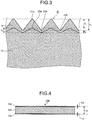
- FIG. 3 is an enlarged view of a region D of FIG. 2 .
- the thickness of the surface layer portion of the screw thread 21 of the screw section 22 of the first alloy section 1a in the radial direction is not necessarily uniform, and a thickness t 1 of an apex 21a is greater than a thickness t 2 of a valley 21b (t 1 > t 2 ).
- the thickness t 2 is, for example, 10 ⁇ m or more and 100 ⁇ m or less.
- the thickness of the surface layer portion of the screw thread 21 in the radial direction is included in the range of 1/2000 or more and 1/10 or less of the maximum outer diameter r 1 of the shaft section 2.
- the height h 2 of the apex 23a is preferably h 1 /4 or more and 3h 1 /4 or less.
- the height h 1 corresponds to the distance in the radial direction from the apex 21a to the valley 21b.
- the height h 2 corresponds to the distance in the radial direction from the apex 23a to a valley 23b of the screw section 22 in the second alloy section 1b.
- FIG. 4 is a cross-sectional view illustrating the configuration of the rod-shaped member for a fastening member which is a raw material of the fastening member 1.
- the rod-shaped member 100 for the fastening member (hereinafter simply referred to as "rod-shaped member 100") illustrated in FIG. 4 has a cylindrical shape of two-layer structure which includes a cylindrical core section 101 made of the same aluminum alloy as that of the second alloy section 1b, and an outer peripheral portion 102 which covers the outer periphery of the core section 101 and is made of the same aluminum alloy as that of the first alloy section 1a.
- a thickness t 100 of the outer peripheral portion 102 is 1/2000 or more and 1/10 or less (r 100 /2000 ⁇ t 100 ⁇ r 100 /10) of the diameter r 100 of the rod-shaped member 100.
- the fastening member 1 is formed by performing a wire drawing, a header process, or the like on the rod-shaped member 100. In order to enable such molding, it is desirable that a breakage elongation at room temperature (about 1 to 35°C) of the aluminum alloy constituting the core section 101 converted into the second alloy section 1b after molding be 8% or more.
- the fastening member 1 When the fastening member 1 is formed by performing the wire drawing and the header process on the rod-shaped member 100, a fiber flow in which the metal crystals are elongated in a fiber shape along the screw surface shape can be seen in the screw section 22. If a crack occurs in the screw section 22, a crack propagates across the fiber flow. Therefore, due to the presence of fiber flow, stress corrosion cracking can be suppressed.
- the aforementioned first embodiment of the present invention by providing a two-layer structure which includes a first alloy section made of an aluminum alloy having excellent stress corrosion cracking resistance in a portion coming into contact with a member to be fastened, and a second alloy section made of an aluminum alloy of high strength in another portion, it is possible to provide a fastening member having excellent strength and stress corrosion cracking resistance.
- the screw threads are formed in a part of the surface of the first alloy section, it is possible to improve the stress corrosion cracking resistance at the contact portion with the member to be fastened.
- the outer peripheral side including the screw thread constitutes a male screw which is the first alloy section
- the thickness of the surface layer portion of the screw thread of the male screw in the radial direction is 1/2000 or more and 1/10 or less of the outer diameter of the screw section. Accordingly, it is possible to achieve both strength and stress corrosion cracking resistance at an appropriate balance.
- a rod-shaped member for a fastening member which is a clad member which includes the outer peripheral portion having a hollow cylindrical shape and made of an aluminum alloy excellent in stress corrosion cracking resistance provided in the portion being in contact with the member to be fastened, and the core section having a cylindrical shape covered with the outer peripheral portion with no gap and made of a high-strength aluminum alloy, it is possible to form a fastening member (a male screw) with excellent strength and stress corrosion cracking resistance by the same manufacturing method as the relate art.
- the thickness of the outer peripheral portion of the rod-shaped member for the fastening member in the radial direction is 1/2000 or more and 1/10 or less of the diameter of the rod-shaped member for the fastening member, it is possible to achieve both strength and stress corrosion cracking resistance at an appropriate balance in the fastening member (male screw) after molding.
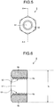
- FIG. 5 is a plan view illustrating a configuration of a fastening member according to the second embodiment of the present invention.
- FIG. 6 is a cross-sectional view taken along line A-A of FIG. 5 .
- a fastening member 5 illustrated in these drawings is a nut (a kind of female screw) made of a clad material formed by joining two kinds of aluminum alloys different from each other.
- the fastening member 5 has a hollow cylindrical shape, and a screw thread 52 is formed on the inner surface of a hole 51 formed at the center portion.
- the shape (a hexagonal nut) of the fastening member 5 illustrated in FIG. 5 is merely an example, and the high strength aluminum alloy can be achieved as a nut (a flanged nut, a cap nut, a high nut, or the like) having another shape.
- the fastening member 5 includes a first alloy section 5a and a second alloy section 5b which are respectively formed, using two different types of aluminum alloys.
- the first alloy section 5a has a ring shape constituting a surface layer portion of the screw thread 52 which is a portion coming into contact with a member to be fastened.
- the second alloy section 5b has a ring shape which covers the outer peripheral surface of the first alloy section 5a.
- the first alloy section 5a is made of the same aluminum alloy as the first alloy section 1a of the first embodiment
- the second alloy section 5b is made of the same aluminum alloy as the second alloy section 1b of the first embodiment.
- the first alloy section 5a is the same as the first alloy section 1a in that the thickness of the first alloy section 5a is 10 ⁇ m or more and 1.5 mm or less.
- the thickness of the first alloy section 5a in the radial direction is 1/2000 or more and 1/10 or less of the maximum outer diameter (circle equivalent outer diameter) r 2 (see FIG. 6 ) of the fastening member 5.
- the second alloy section 5b is the same as the second alloy section 1b in that the Vickers hardness of the second alloy section 5b is 130 or more and that the breakage elongation at room temperature of the second alloy section 5b is 8% or more.
- the thickness of the surface layer portion of the screw thread 52 of the first alloy section 5a in the radial direction is not necessarily uniform, and is included in the range of 1/2000 or more and 1/10 or less of the maximum outer diameter (circle equivalent outer diameter) r 2 of the fastening member 5.
- the entire screw threads 52 which are portions coming in contact with the member to be fastened, become aluminum alloys having excellent stress corrosion cracking resistance.
- FIG. 7 is a cross-sectional view illustrating a configuration of a rod-shaped member for a fastening member which is a raw material of the fastening member 5.
- a rod-shaped member 200 for the fastening member (hereinafter simply referred to as "rod-shaped member 200") illustrated in FIG. 7 is a cylindrical clad material of a two-layer structure which includes a cylindrical core section 201 made of the same aluminum alloy as the first alloy section 5a, and an outer peripheral portion 202 which covers the outer periphery of the core section 201 with no gap and is made of the same aluminum alloy as the second alloy section 5b.
- the fastening member 5 is formed by performing the wire drawing on the rod-shaped member 200, the digging process of the core section 201, the header process, and the like. In order to enable such molding, it is desirable that the breakage elongation at room temperature of the aluminum alloy constituting the outer peripheral portion 202 to be the second alloy section 5b after molding be 8% or more.
- FIG. 8 is a cross-sectional view illustrating a configuration after performing the digging process of the core section 201 with respect to the rod-shaped member 200.
- a rod-shaped member 200' illustrated in FIG. 8 includes a hollow cylindrical core section 201', and an outer peripheral portion 202' which covers the side surface of the core section 201' with no gap.
- a thickness t 200 of the core section 201' in the radial direction is 1/2000 or more and 1/10 or less (r 200 /2000 ⁇ t 200 ⁇ r 200 /10) of a diameter r 200 of the rod-shaped member 200'.
- a rod-shaped member 200' having a core section 201' in which a hole 211' is formed by performing the digging process is obtained. Thereafter, by performing the header process or the like on the rod-shaped member 200', the fastening member 5 is formed. Further, the wire drawing may be performed after performing the digging process on the rod-shaped member 200. Further, after the wire drawing is performed on the rod-shaped member 200, the rod-shaped member 200 is cut to a length necessary for forming the fastening member 5 (nut), and then the digging process may be performed.
- the fastening member having excellent strength and stress corrosion cracking resistance as in the first embodiment.
- the screw threads are formed on a part of the surface of the first alloy section, it is possible to improve the stress corrosion cracking resistance at the contact portion with the member to be fastened.
- the inner peripheral side constitutes the female screw which is the first alloy section
- the thickness of the first alloy section in the radial direction is 1/2000 or more and 1/10 or less of the maximum outer diameter of the female screw. Accordingly, it is possible to achieve both strength and stress corrosion cracking resistance at an appropriate balance.
- a rod-shaped member for a fastening member which includes the core section having a hollow cylindrical shape and made of an aluminum alloy excellent in stress corrosion cracking resistance in the portion being in contact with the member to be fastened, and the outer peripheral portion which has a cylindrical shape to cover the outer periphery of the deep part and is made of a high-strength aluminum alloy, and in which the thickness of the core section in the radial direction is 1/2000 or more and 1/10 or less of the maximum outer diameter of the outer peripheral portion, it is possible to form a fastening member (nut) in which both strength and stress corrosion cracking resistance are achieved at an appropriate balance by the same manufacturing method as the related art.
- FIG. 9 is a side view illustrating a configuration of a fastening member according to a third embodiment of the present invention.
- FIG. 10 is a cross-sectional view passing through the central axis of the fastening member illustrated in FIG. 9 in the longitudinal direction (left-right direction in FIG. 9 ).
- a fastening member 6 illustrated in these drawings is a rivet made of a clad material formed by joining two kinds of aluminum alloys different from each other.
- the fastening member 6 includes a cylindrical shaft section 7, a head section 8 provided at one end of a cylinder forming the shaft section 7 in the height direction (left-right direction in FIG. 9 ), and a neck section 9 demarcating a boundary between the shaft section 7 and the head section 8.
- the shape (round shape) of the head section 8 illustrated in FIG. 9 is merely an example, and other shapes (a dish shape or the like) may be provided.
- the fastening member 6 includes a first alloy section 6a and a second alloy section 6b which are respectively formed, using two different types of aluminum alloys.
- the first alloy section 6a is provided at a portion which is in contact with a member to be fastened.
- the first alloy section 6a forms the surface layer portion of the shaft section 7, the surface of the neck section 9, the surface layer portion of a seating surface 81 of the head section 8, and at least a part of the surface layer portion of the region continued to the seating surface 81 of a surface 82 of the head section 8.
- the second alloy section 6b constitutes a portion other than the inner peripheral side of the shaft section 7 and the first alloy section 6a of the head section 8.
- the first alloy section 6a is made of the same aluminum alloy as the first alloy section 1a of the first embodiment
- the second alloy section 6b is made of the same aluminum alloy as the second alloy section 1b of the first embodiment.
- the first alloy section 6a is the same as the first alloy section 1a in that the thickness of the first alloy section 6a is 10 ⁇ m or more and 1.5 mm or less.
- a thickness t 3 in the radial direction of the first alloy section 6a in the shaft section 7 is 1/2000 or more and 1/10 or less of the outer diameter r 3 (see FIG. 10 ) of the shaft section 7.
- the second alloy section 6b is the same as the second alloy section 1b in that the Vickers hardness of the second alloy section 6b is 130 or more, and the breakage elongation at room temperature of the second alloy section 6b is 8% or more.
- the thickness t 3 of the first alloy section 6a in the shaft section 7 is 1/2000 or more and 1/10 or less (r 3 /2000 ⁇ t 3 ⁇ r 3 /10) of the outer diameter r 3 of the shaft section 7.
- Such a fastening member 6 can be formed by performing the wire drawing, the header process, or the like on the rod-shaped member 100 illustrated in FIG. 4 .
- the aforementioned third embodiment of the present invention by adopting a two-layer structure in which the first alloy section made of an aluminum alloy having excellent stress corrosion cracking resistance is provided in the portion being in contact with the member to be fastened, and the second alloy section made of an aluminum alloy having excellent strength is provided in other portions, it is possible to provide a fastening member with excellent strength and stress corrosion cracking resistance as in the first embodiment.
- the rivet in which the outer peripheral side is the first alloy section is formed, and the thickness of the first alloy section in the shaft section of the rivet in the radial direction is 1/2000 or more and 1/10 or less of the outer diameter of the shaft section, it is possible to achieve both strength and stress corrosion cracking resistance at an appropriate balance.
- a rod-shaped member for a fastening member which is a clad material which includes an outer peripheral portion having a hollow cylindrical shape and made of an aluminum alloy with excellent stress corrosion cracking resistance in a portion being in contact with the member to be fastened, and a core section having a cylindrical shape covered with the outer peripheral portion with no gap and made of a high-strength aluminum alloy, it is possible to form a fastening member (rivet) having excellent strength and stress corrosion cracking resistance by the same manufacturing method as the related art.
- the thickness of the outer peripheral portion of the rod-shaped member for the fastening member in the radial direction is 1/2000 or more and 1/10 or less of the diameter of the rod-shaped member for the fastening member, it is possible to achieve both strength and stress corrosion cracking resistance at an appropriate balance in the fastening member (rivet) after the molding.
- the present invention should not be limited only by the above described first to third embodiments.
- the fastening member according to the present invention as a small screw or a tapping screw which is a male screw other than a bolt.
- an aluminum alloy having excellent stress corrosion cracking resistance for example, an aluminum alloy of 3000 series, 4000 series, 5000 series, 6000 series, and 7000 series can be adopted.
- the present invention can include various embodiments and the like which are not described here, and various design changes and the like can be made within the scope that does not depart from the technical idea specified by the claims.
- the fastening member according to the present invention, and the rod-shaped member for the fastening member used for manufacturing the fastening member are suitable for obtaining a fastening member with excellent strength and stress corrosion cracking resistance.
Landscapes
- Engineering & Computer Science (AREA)
- General Engineering & Computer Science (AREA)
- Mechanical Engineering (AREA)
- Chemical & Material Sciences (AREA)
- Materials Engineering (AREA)
- Metallurgy (AREA)
- Organic Chemistry (AREA)
- Insertion Pins And Rivets (AREA)
- Connection Of Plates (AREA)
- Shafts, Cranks, Connecting Bars, And Related Bearings (AREA)
Description
- The present invention relates to a fastening member which fastens a plurality of members, and a rod-shaped member for a fastening member used for manufacturing the fastening member.
- Conventionally, as a measure for achieving improvement in fuel economy of automobiles, weight reduction of various components has been pursued. For example, an aluminum alloy is used instead of cast iron as a material for an engine block, or a magnesium alloy is used instead of steel as a material for an engine cover or an oil pan.
- In the case where the components made of the aluminum alloy or magnesium alloy as mentioned above are fastened by a conventional steel bolt, looseness is likely to occur due to a large difference between the linear expansion coefficient of the aluminum alloy or the magnesium alloy and the linear expansion coefficient of the steel, and corrosion due to contact of dissimilar metals is also likely to occur. Therefore, in order to sufficiently secure the reliability of fastening, it is necessary to deepen the screw hole of the component to lengthen the shaft section length of the steel bolt, or thicken the diameter of the steel bolt. However, the length of the shaft section of the steel bolt influences the wall thickness of the component, and meanwhile, the thickness of the steel bolt influences the width of the flange portion providing the screw hole of the component. Thus, the use of the steel bolts for fastening the components made of aluminum alloy or magnesium alloy has been an obstacle in pursuing the weight reduction.
- In order to solve such a problem of steel bolts, the movement of adopting an aluminum alloy bolt as a fastening member for fastening the components made of an aluminum alloy or a magnesium alloy has also been expanded (see, for example, Patent Literature 1). In Patent Literature 1, a 6000 series aluminum alloy is disclosed as a material for a bolt which is excellent in workability at the time of manufacturing the bolt and has sufficient strength. Since the aluminum alloy bolts have small difference in linear expansion coefficient with aluminum alloys or magnesium alloys constituting various components and small galvanic corrosion, even if the screw hole of the component is made shallow or the diameter of the bolt is thinned, the reliability of the fastening can be secured, which is suitable for achieving weight reduction.
- 2000 series aluminum alloy is known as an aluminum alloy having a higher strength than the aforementioned 6000 series aluminum alloy. When using 2000 series aluminum alloy, it is possible to make bolts of higher strength than bolts made of 6000 series aluminum alloy.
- Patent Literature 1:
JP 5335056 B2 - However, since 2000 series aluminum alloys are generally inferior to 6000 series aluminum alloys in stress corrosion cracking resistance, it was necessary to improve the stress corrosion cracking resistance when applied as bolts. Under such circumstances, a fastening member made of a material excellent in strength and stress corrosion cracking resistance has been required.
- The present invention has been made in view of the above circumstances, and an object thereof is to provide a fastening member excellent in strength and stress corrosion cracking resistance, and a rod-shaped member for a fastening member used for manufacturing the fastening member.
- To solve the above-described problem and achieve the object, a fastening member according to the present invention fastens members, and includes: a first alloy section made of aluminum alloy containing zinc in an amount of 0.005 wt% or more and 6.5 wt% or less and containing magnesium in an amount of 0.6 wt% or more and 2.0 wt% or less, is the first alloy section being provided in a portion in contact with at least one of the members; and a second alloy section made of an aluminum alloy containing magnesium in an amount of greater than 0.2 wt% and 2.3 wt% or less and containing copper in an amount of greater than 1.0 wt% and 8.0 wt% or less, the second alloy section being bonded to the first alloy section.
- In the above-described fastening member according to the present invention, Vickers hardness of the second alloy section is 130 or more.
- In the above-described fastening member according to the present invention, a screw thread is formed in a part of a surface of the first alloy section.
- In the above-described fastening member according to the present invention, the fastening member is a male screw including: a cylindrical shaft section with the screw thread formed in at least a part of the outer periphery; a head section provided at one end of the shaft section in an axial direction; and a neck section demarcating a boundary between the shaft section and the head section, the first alloy section constitutes at least a surface layer portion of the screw thread, a surface of the neck section and a surface layer portion of a seating surface of the head section, and a thickness of the surface layer portion of the screw thread of the first alloy section in the radial direction is 1/2000 or more and 1/10 or less of a maximum outer diameter of the shaft section.
- In the above-described fastening member according to the present invention, the fastening member is a female screw with the screw thread formed on an inner surface of a hole formed in a center portion, the second alloy section is located on an outer peripheral side of the first alloy section, and a thickness of the first alloy section in the radial direction is 1/2000 or more and 1/10 or less of a maximum outer diameter of the female screw.
- In the above-described fastening member according to the present invention, the fastening member is a rivet including: a cylindrical shaft section; a head section provided at one end portion of the shaft section in the axial direction; and a neck section demarcating a boundary between the shaft section and the head section, the first alloy section constitutes at least a surface layer portion of the shaft section, a surface of the neck section and a surface layer portion of a seating surface of the head section, and a thickness of the first alloy section in the radial direction of the shaft section is 1/2000 or more and 1/10 or less of an outer diameter of the shaft section.
- A rod-shaped member for a fastening member according to the present invention includes: a core section having a cylindrical shape and made of an aluminum alloy containing magnesium in an amount of greater than 0.2 wt% and 2.3 wt% or less and copper containing in an amount of greater than 1.0 wt% and 8.0 wt% or less; and an outer peripheral portion having a hollow cylindrical shape covering a side surface of the core section with no gap, and made of an aluminum alloy containing zinc in an amount of 0.005 wt% or more and 6.5 wt% or less and containing magnesium in an amount of 0.6 wt% or more and 2.0 wt% or less.
- In the above-described rod-shaped member for a fastening member according to the present invention, a thickness of the outer peripheral portion in the radial direction is 1/2000 or more and 1/10 or less of a maximum outer diameter of the outer peripheral portion.
- A rod-shaped member for a fastening member according to the present invention includes: a core section having a hollow cylindrical shape and made of an aluminum alloy containing zinc in an amount of 0.005 wt% or more and 6.5 wt% or less and containing magnesium in an amount of 0.6 wt% or more and 2.0 wt% or less; and an outer peripheral portion having a hollow cylindrical shape covering a side surface of the core section with no gap, and made of an aluminum alloy containing magnesium in an amount of greater than 0.2 wt% and 2.3 wt% or less and containing copper in an amount of greater than 1.0 wt% and 8.0 wt% or less.
- In the above-described rod-shaped member for a fastening member according to the present invention, a thickness of the core section in the radial direction is 1/2000 or more and 1/10 or less of a maximum outer diameter of the outer peripheral portion.
- According to the present invention, it is possible to provide a fastening member excellent in strength and stress corrosion cracking resistance, by utilizing a clad material including a high-strength aluminum alloy and an aluminum alloy having excellent stress corrosion cracking resistance.
-
-
FIG. 1 is a side view illustrating a configuration of a fastening member according to a first embodiment of the present invention. -
FIG. 2 is a cross-sectional view passing through a center axis of the fastening member illustrated inFIG. 1 . -
FIG. 3 is an enlarged view of a region D ofFIG. 2 . -
FIG. 4 is a cross-sectional view illustrating a configuration of a rod-shaped member for a fastening member according to a first embodiment of the present invention. -
FIG. 5 is a plan view illustrating a configuration of a fastening member according to a second embodiment of the present invention. -
FIG. 6 is a cross-sectional view taken along line A-A ofFIG. 5 . -
FIG. 7 is a cross-sectional view illustrating a configuration of a rod-shaped member for a fastening member according to the second embodiment of the present invention. -
FIG. 8 is a cross-sectional view illustrating a configuration after performing a digging process on the rod-shaped member for the fastening member according to the second embodiment of the present invention. -
FIG. 9 is a side view illustrating a configuration of a fastening member according to a third embodiment of the present invention. -
FIG. 10 is a cross-sectional view passing through the center axis of the fastening member illustrated inFIG. 9 . Description of Embodiments - Hereinafter, a mode for carrying out the present invention (hereinafter referred to as "embodiment") will be described with reference to the accompanying drawings. It should be noted that the drawings are schematic and a relation between the thickness and the width of each portion, the ratio of the thickness of each portion, and the like may be different from the actual ones, and parts with different dimensional relations and ratios may be included in each drawing.
-
FIG. 1 is a side view illustrating a configuration of a fastening member according to a first embodiment of the present invention.FIG. 2 is a cross-sectional view passing through a central axis of a fastening member illustrated inFIG. 1 in a longitudinal direction (a left-right direction ofFIG. 1 ). A fastening member 1 illustrated in these drawings is a bolt (a kind of male screw) made of a clad material formed by joining two different kinds of aluminum (Al) alloys. The fastening member 1 includes ashaft section 2 having a cylindrical shape, ahead section 3 provided at one end of theshaft section 2 in an axial direction (the left-right direction inFIG. 1 ), and aneck section 4 which demarcates a boundary between theshaft section 2 and thehead section 3. Theshaft section 2 has ascrew section 22 having ascrew thread 21 formed on its surface. The shape (hexagonal trim type) of thehead section 3 illustrated inFIG. 1 is merely an example, and thehead section 3 may have other shapes (a hexagonal flange type, a pan type, a dish type, a truss type, a flat type, etc.). - The fastening member 1 has a
first alloy section 1a and asecond alloy section 1b respectively formed using two kinds of aluminum alloys different from each other. Thefirst alloy section 1a is provided in a portion being in contact with a member to be fastened. That is, thefirst alloy section 1a constitutes a surface layer portion of theshaft section 2 including thescrew thread 21, the surface of theneck section 4, and aseating surface 31 and the surface layer portion of aside surface 32 of thehead section 3. Thesecond alloy section 1b constitutes a radially inner peripheral side of theshaft section 2 and thehead section 3, and is joined to thefirst alloy section 1a. A portion which is not in contact with any of the plurality of members may be configured so that thesecond alloy section 1b is exposed, in a state in which a plurality of members to be fastened is fastened by the fastening member 1. - The
first alloy section 1a is made of an aluminum alloy containing zinc (Zn) in an amount of 0.005 wt% or more and 6.5 wt% or less and containing magnesium (Mg) in an amount of 0.6 wt% or more and 2.0 wt% or less. The aluminum alloy preferably contains at least one kind of element or more selected from the group consisting of copper (Cu), chromium (Cr), zirconium (Zr), iron (Fe), silicon (Si), manganese (Mn), titanium (Ti), vanadium (V), scandium (Sc), nickel (Ni), and bismuth (Bi). As an aluminum alloy having such a composition, for example, A6056 can be adopted. A6056 is an alloy containing Al-Mg-Si as a main element, and is known as an aluminum alloy having relatively high strength and excellent stress corrosion cracking resistance. The thickness of thefirst alloy section 1a is 10 µm or more and 1.5 mm or less. In particular, the radial thickness of thefirst alloy section 1a in theshaft section 2 is 1/2000 or more and 1/10 or less of a maximum outer diameter r1 (seeFIG. 2 ) of theshaft section 2. - The
second alloy section 1b is made of an aluminum alloy containing magnesium (Mg) in an amount of greater than 0.2 wt% and 2.3 wt% or less and containing copper (Cu) in an amount of greater than 1.0 wt% and 8.0 wt% or less. The aluminum alloy preferably contains at least one kind of element or more selected from the group consisting of zinc (Zn), chromium (Cr), zirconium (Zr), iron (Fe), silicon (Si), manganese (Mn), titanium (Ti), vanadium (V), and scandium (Sc). For example, the aluminum alloy constituting thesecond alloy section 1b preferably contains zinc (Zn) in an amount of 0.5 wt% or less, manganese in an amount of 1.2 wt% or less, zirconium in an amount of 0.25 wt% or less, and nickel in an amount of 2.5 wt% or less, in addition to the aforementioned magnesium and copper. As an aluminum alloy having such a composition, for example, A2024 and A2618 can be adopted. A2024 and A2618 are known as high-strength aluminum alloys. As a specific strength of thesecond alloy section 1b, it is desirable that the Vickers hardness be 130 or more. -
FIG. 3 is an enlarged view of a region D ofFIG. 2 . As illustrated inFIG. 3 , the thickness of the surface layer portion of thescrew thread 21 of thescrew section 22 of thefirst alloy section 1a in the radial direction is not necessarily uniform, and a thickness t1 of an apex 21a is greater than a thickness t2 of avalley 21b (t1 > t2). The thickness t2 is, for example, 10 µm or more and 100 µm or less. The thickness of the surface layer portion of thescrew thread 21 in the radial direction is included in the range of 1/2000 or more and 1/10 or less of the maximum outer diameter r1 of theshaft section 2. As a result, all the portions of thescrew section 22 which are at least in contact with the members to be fastened become aluminum alloys having excellent stress corrosion cracking resistance. - Further, when the height of the apex 21a of the
screw section 22 in thefirst alloy section 1a is set as h1, and the height of an apex 23a of thescrew section 22 in thesecond alloy section 1b is set as h2, the height h2 of the apex 23a is preferably h1/4 or more and 3h1/4 or less. Here, the height h1 corresponds to the distance in the radial direction from the apex 21a to thevalley 21b. Further, the height h2 corresponds to the distance in the radial direction from the apex 23a to avalley 23b of thescrew section 22 in thesecond alloy section 1b. -
FIG. 4 is a cross-sectional view illustrating the configuration of the rod-shaped member for a fastening member which is a raw material of the fastening member 1. The rod-shapedmember 100 for the fastening member (hereinafter simply referred to as "rod-shapedmember 100") illustrated inFIG. 4 has a cylindrical shape of two-layer structure which includes acylindrical core section 101 made of the same aluminum alloy as that of thesecond alloy section 1b, and an outerperipheral portion 102 which covers the outer periphery of thecore section 101 and is made of the same aluminum alloy as that of thefirst alloy section 1a. A thickness t100 of the outerperipheral portion 102 is 1/2000 or more and 1/10 or less (r100/2000 ≤ t100 ≤ r100/10) of the diameter r100 of the rod-shapedmember 100. The fastening member 1 is formed by performing a wire drawing, a header process, or the like on the rod-shapedmember 100. In order to enable such molding, it is desirable that a breakage elongation at room temperature (about 1 to 35°C) of the aluminum alloy constituting thecore section 101 converted into thesecond alloy section 1b after molding be 8% or more. - When the fastening member 1 is formed by performing the wire drawing and the header process on the rod-shaped
member 100, a fiber flow in which the metal crystals are elongated in a fiber shape along the screw surface shape can be seen in thescrew section 22. If a crack occurs in thescrew section 22, a crack propagates across the fiber flow. Therefore, due to the presence of fiber flow, stress corrosion cracking can be suppressed. - According to the aforementioned first embodiment of the present invention, by providing a two-layer structure which includes a first alloy section made of an aluminum alloy having excellent stress corrosion cracking resistance in a portion coming into contact with a member to be fastened, and a second alloy section made of an aluminum alloy of high strength in another portion, it is possible to provide a fastening member having excellent strength and stress corrosion cracking resistance.
- Further, according to the first embodiment, since the screw threads are formed in a part of the surface of the first alloy section, it is possible to improve the stress corrosion cracking resistance at the contact portion with the member to be fastened.
- Further, according to the first embodiment, the outer peripheral side including the screw thread constitutes a male screw which is the first alloy section, and the thickness of the surface layer portion of the screw thread of the male screw in the radial direction is 1/2000 or more and 1/10 or less of the outer diameter of the screw section. Accordingly, it is possible to achieve both strength and stress corrosion cracking resistance at an appropriate balance.
- Further, according to the first embodiment, by forming a rod-shaped member for a fastening member which is a clad member which includes the outer peripheral portion having a hollow cylindrical shape and made of an aluminum alloy excellent in stress corrosion cracking resistance provided in the portion being in contact with the member to be fastened, and the core section having a cylindrical shape covered with the outer peripheral portion with no gap and made of a high-strength aluminum alloy, it is possible to form a fastening member (a male screw) with excellent strength and stress corrosion cracking resistance by the same manufacturing method as the relate art.
- Further, according to the first embodiment, since the thickness of the outer peripheral portion of the rod-shaped member for the fastening member in the radial direction is 1/2000 or more and 1/10 or less of the diameter of the rod-shaped member for the fastening member, it is possible to achieve both strength and stress corrosion cracking resistance at an appropriate balance in the fastening member (male screw) after molding.
-
FIG. 5 is a plan view illustrating a configuration of a fastening member according to the second embodiment of the present invention.FIG. 6 is a cross-sectional view taken along line A-A ofFIG. 5 . Afastening member 5 illustrated in these drawings is a nut (a kind of female screw) made of a clad material formed by joining two kinds of aluminum alloys different from each other. Thefastening member 5 has a hollow cylindrical shape, and ascrew thread 52 is formed on the inner surface of ahole 51 formed at the center portion. The shape (a hexagonal nut) of thefastening member 5 illustrated inFIG. 5 is merely an example, and the high strength aluminum alloy can be achieved as a nut (a flanged nut, a cap nut, a high nut, or the like) having another shape. - The
fastening member 5 includes afirst alloy section 5a and asecond alloy section 5b which are respectively formed, using two different types of aluminum alloys. Thefirst alloy section 5a has a ring shape constituting a surface layer portion of thescrew thread 52 which is a portion coming into contact with a member to be fastened. Thesecond alloy section 5b has a ring shape which covers the outer peripheral surface of thefirst alloy section 5a. - The
first alloy section 5a is made of the same aluminum alloy as thefirst alloy section 1a of the first embodiment, and thesecond alloy section 5b is made of the same aluminum alloy as thesecond alloy section 1b of the first embodiment. Thefirst alloy section 5a is the same as thefirst alloy section 1a in that the thickness of thefirst alloy section 5a is 10 µm or more and 1.5 mm or less. The thickness of thefirst alloy section 5a in the radial direction is 1/2000 or more and 1/10 or less of the maximum outer diameter (circle equivalent outer diameter) r2 (seeFIG. 6 ) of thefastening member 5. Further, thesecond alloy section 5b is the same as thesecond alloy section 1b in that the Vickers hardness of thesecond alloy section 5b is 130 or more and that the breakage elongation at room temperature of thesecond alloy section 5b is 8% or more. - The thickness of the surface layer portion of the
screw thread 52 of thefirst alloy section 5a in the radial direction is not necessarily uniform, and is included in the range of 1/2000 or more and 1/10 or less of the maximum outer diameter (circle equivalent outer diameter) r2 of thefastening member 5. As a result, at least theentire screw threads 52, which are portions coming in contact with the member to be fastened, become aluminum alloys having excellent stress corrosion cracking resistance. -
FIG. 7 is a cross-sectional view illustrating a configuration of a rod-shaped member for a fastening member which is a raw material of thefastening member 5. A rod-shapedmember 200 for the fastening member (hereinafter simply referred to as "rod-shapedmember 200") illustrated inFIG. 7 is a cylindrical clad material of a two-layer structure which includes acylindrical core section 201 made of the same aluminum alloy as thefirst alloy section 5a, and an outerperipheral portion 202 which covers the outer periphery of thecore section 201 with no gap and is made of the same aluminum alloy as thesecond alloy section 5b. Thefastening member 5 is formed by performing the wire drawing on the rod-shapedmember 200, the digging process of thecore section 201, the header process, and the like. In order to enable such molding, it is desirable that the breakage elongation at room temperature of the aluminum alloy constituting the outerperipheral portion 202 to be thesecond alloy section 5b after molding be 8% or more. -
FIG. 8 is a cross-sectional view illustrating a configuration after performing the digging process of thecore section 201 with respect to the rod-shapedmember 200. A rod-shaped member 200' illustrated inFIG. 8 includes a hollowcylindrical core section 201', and an outer peripheral portion 202' which covers the side surface of thecore section 201' with no gap. Among them, a thickness t200 of thecore section 201' in the radial direction is 1/2000 or more and 1/10 or less (r200/2000 ≤ t200 ≤ r200/10) of a diameter r200 of the rod-shaped member 200'. In the second embodiment, after the wire drawing is performed on the rod-shapedmember 200, a rod-shaped member 200' having acore section 201' in which ahole 211' is formed by performing the digging process is obtained. Thereafter, by performing the header process or the like on the rod-shaped member 200', thefastening member 5 is formed. Further, the wire drawing may be performed after performing the digging process on the rod-shapedmember 200. Further, after the wire drawing is performed on the rod-shapedmember 200, the rod-shapedmember 200 is cut to a length necessary for forming the fastening member 5 (nut), and then the digging process may be performed. - According to the aforementioned second embodiment of the present invention, by providing a two-layer structure which includes the first alloy section made of an aluminum alloy excellent in stress corrosion cracking resistance in the portion coming into contact with the member to be fastened, and the second alloy section made of an aluminum alloy having excellent strength at the outer peripheral side of the first alloy section, it is possible to provide the fastening member having excellent strength and stress corrosion cracking resistance as in the first embodiment.
- Further, according to the second embodiment, since the screw threads are formed on a part of the surface of the first alloy section, it is possible to improve the stress corrosion cracking resistance at the contact portion with the member to be fastened.
- Further, according to the second embodiment, the inner peripheral side constitutes the female screw which is the first alloy section, and the thickness of the first alloy section in the radial direction is 1/2000 or more and 1/10 or less of the maximum outer diameter of the female screw. Accordingly, it is possible to achieve both strength and stress corrosion cracking resistance at an appropriate balance.
- Further, according to the second embodiment, by forming a rod-shaped member for a fastening member which includes the core section having a hollow cylindrical shape and made of an aluminum alloy excellent in stress corrosion cracking resistance in the portion being in contact with the member to be fastened, and the outer peripheral portion which has a cylindrical shape to cover the outer periphery of the deep part and is made of a high-strength aluminum alloy, and in which the thickness of the core section in the radial direction is 1/2000 or more and 1/10 or less of the maximum outer diameter of the outer peripheral portion, it is possible to form a fastening member (nut) in which both strength and stress corrosion cracking resistance are achieved at an appropriate balance by the same manufacturing method as the related art.
-
FIG. 9 is a side view illustrating a configuration of a fastening member according to a third embodiment of the present invention.FIG. 10 is a cross-sectional view passing through the central axis of the fastening member illustrated inFIG. 9 in the longitudinal direction (left-right direction inFIG. 9 ). Afastening member 6 illustrated in these drawings is a rivet made of a clad material formed by joining two kinds of aluminum alloys different from each other. Thefastening member 6 includes acylindrical shaft section 7, ahead section 8 provided at one end of a cylinder forming theshaft section 7 in the height direction (left-right direction inFIG. 9 ), and aneck section 9 demarcating a boundary between theshaft section 7 and thehead section 8. It should be noted that the shape (round shape) of thehead section 8 illustrated inFIG. 9 is merely an example, and other shapes (a dish shape or the like) may be provided. - The
fastening member 6 includes afirst alloy section 6a and asecond alloy section 6b which are respectively formed, using two different types of aluminum alloys. Thefirst alloy section 6a is provided at a portion which is in contact with a member to be fastened. In other words, thefirst alloy section 6a forms the surface layer portion of theshaft section 7, the surface of theneck section 9, the surface layer portion of aseating surface 81 of thehead section 8, and at least a part of the surface layer portion of the region continued to theseating surface 81 of asurface 82 of thehead section 8. Thesecond alloy section 6b constitutes a portion other than the inner peripheral side of theshaft section 7 and thefirst alloy section 6a of thehead section 8. - The
first alloy section 6a is made of the same aluminum alloy as thefirst alloy section 1a of the first embodiment, and thesecond alloy section 6b is made of the same aluminum alloy as thesecond alloy section 1b of the first embodiment. Thefirst alloy section 6a is the same as thefirst alloy section 1a in that the thickness of thefirst alloy section 6a is 10 µm or more and 1.5 mm or less. Further, a thickness t3 in the radial direction of thefirst alloy section 6a in theshaft section 7 is 1/2000 or more and 1/10 or less of the outer diameter r3 (seeFIG. 10 ) of theshaft section 7. Furthermore, thesecond alloy section 6b is the same as thesecond alloy section 1b in that the Vickers hardness of thesecond alloy section 6b is 130 or more, and the breakage elongation at room temperature of thesecond alloy section 6b is 8% or more. - The thickness t3 of the
first alloy section 6a in theshaft section 7 is 1/2000 or more and 1/10 or less (r3/2000 ≤ t3 ≤ r3/10) of the outer diameter r3 of theshaft section 7. Such afastening member 6 can be formed by performing the wire drawing, the header process, or the like on the rod-shapedmember 100 illustrated inFIG. 4 . - According to the aforementioned third embodiment of the present invention, by adopting a two-layer structure in which the first alloy section made of an aluminum alloy having excellent stress corrosion cracking resistance is provided in the portion being in contact with the member to be fastened, and the second alloy section made of an aluminum alloy having excellent strength is provided in other portions, it is possible to provide a fastening member with excellent strength and stress corrosion cracking resistance as in the first embodiment.
- According to the third embodiment, since the rivet in which the outer peripheral side is the first alloy section is formed, and the thickness of the first alloy section in the shaft section of the rivet in the radial direction is 1/2000 or more and 1/10 or less of the outer diameter of the shaft section, it is possible to achieve both strength and stress corrosion cracking resistance at an appropriate balance.
- Further, according to the third embodiment, by forming a rod-shaped member for a fastening member which is a clad material which includes an outer peripheral portion having a hollow cylindrical shape and made of an aluminum alloy with excellent stress corrosion cracking resistance in a portion being in contact with the member to be fastened, and a core section having a cylindrical shape covered with the outer peripheral portion with no gap and made of a high-strength aluminum alloy, it is possible to form a fastening member (rivet) having excellent strength and stress corrosion cracking resistance by the same manufacturing method as the related art.
- Further, according to the third embodiment, since the thickness of the outer peripheral portion of the rod-shaped member for the fastening member in the radial direction is 1/2000 or more and 1/10 or less of the diameter of the rod-shaped member for the fastening member, it is possible to achieve both strength and stress corrosion cracking resistance at an appropriate balance in the fastening member (rivet) after the molding.
- Although the mode for carrying out the present invention has been described here, the present invention should not be limited only by the above described first to third embodiments. For example, it is also possible to achieve the fastening member according to the present invention as a small screw or a tapping screw which is a male screw other than a bolt.
- Further, in the present invention, it is also possible to provide a layer made of an aluminum alloy having excellent stress corrosion cracking resistance on the surface of the first alloy section. As such an aluminum alloy, for example, an aluminum alloy of 3000 series, 4000 series, 5000 series, 6000 series, and 7000 series can be adopted.
- As described above, the present invention can include various embodiments and the like which are not described here, and various design changes and the like can be made within the scope that does not depart from the technical idea specified by the claims.
- As described above, the fastening member according to the present invention, and the rod-shaped member for the fastening member used for manufacturing the fastening member are suitable for obtaining a fastening member with excellent strength and stress corrosion cracking resistance.
-
- 1, 5, 6 Fastening member
- 1a, 5a, 6a First alloy section
- 1b, 5b, 6b Second alloy section
- 2, 7 Shaft section
- 3, 8 Head section
- 4, 9 Neck section
- 21, 52 Screw thread
- 21a Apex
- 21b Valley
- 22 Screw section
- 31, 81 Seating surface
- 32 Side surface
- 51, 211' Hole
- 82 Surface
- 100, 200, 200' Rod-shaped member for fastening member
- 101, 201, 201' Core section
- 102, 202, 202' Outer peripheral portion
Claims (10)
- A fastening member that fastens members, the fastening member comprising:a first alloy section made of aluminum alloy containing zinc in an amount of 0.005 wt% or more and 6.5 wt% or less and containing magnesium in an amount of 0.6 wt% or more and 2.0 wt% or less, is the first alloy section being provided in a portion in contact with at least one of the members; anda second alloy section made of an aluminum alloy containing magnesium in an amount of greater than 0.2 wt% and 2.3 wt% or less and containing copper in an amount of greater than 1.0 wt% and 8.0 wt% or less, the second alloy section being bonded to the first alloy section.
- The fastening member according to claim 1, wherein Vickers hardness of the second alloy section is 130 or more.
- The fastening member according to claim 1 or 2, wherein a screw thread is formed in a part of a surface of the first alloy section.
- The fastening member according to claim 3, wherein
the fastening member is a male screw including:a cylindrical shaft section with the screw thread formed in at least a part of the outer periphery;a head section provided at one end of the shaft section in an axial direction; anda neck section demarcating a boundary between the shaft section and the head section,the first alloy section constitutes at least a surface layer portion of the screw thread, a surface of the neck section and a surface layer portion of a seating surface of the head section, and
a thickness of the surface layer portion of the screw thread of the first alloy section in the radial direction is 1/2000 or more and 1/10 or less of a maximum outer diameter of the shaft section. - The fastening member according to claim 3, wherein
the fastening member is a female screw with the screw thread formed on an inner surface of a hole formed in a center portion,
the second alloy section is located on an outer peripheral side of the first alloy section, and
a thickness of the first alloy section in the radial direction is 1/2000 or more and 1/10 or less of a maximum outer diameter of the female screw. - The fastening member according to claim 1 or 2, wherein
the fastening member is a rivet including:a cylindrical shaft section;a head section provided at one end portion of the shaft section in the axial direction; anda neck section demarcating a boundary between the shaft section and the head section,the first alloy section constitutes at least a surface layer portion of the shaft section, a surface of the neck section and a surface layer portion of a seating surface of the head section, and
a thickness of the first alloy section in the radial direction of the shaft section is 1/2000 or more and 1/10 or less of an outer diameter of the shaft section. - A rod-shaped member for a fastening member, comprising:a core section having a cylindrical shape and made of an aluminum alloy containing magnesium in an amount of greater than 0.2 wt% and 2.3 wt% or less and copper containing in an amount of greater than 1.0 wt% and 8.0 wt% or less; andan outer peripheral portion having a hollow cylindrical shape covering a side surface of the core section with no gap, and made of an aluminum alloy containing zinc in an amount of 0.005 wt% or more and 6.5 wt% or less and containing magnesium in an amount of 0.6 wt% or more and 2.0 wt% or less.
- The rod-shaped member for a fastening member according to claim 7, wherein a thickness of the outer peripheral portion in the radial direction is 1/2000 or more and 1/10 or less of a maximum outer diameter of the outer peripheral portion.
- A rod-shaped member for a fastening member, comprising:a core section having a hollow cylindrical shape and made of an aluminum alloy containing zinc in an amount of 0.005 wt% or more and 6.5 wt% or less and containing magnesium in an amount of 0.6 wt% or more and 2.0 wt% or less; andan outer peripheral portion having a hollow cylindrical shape covering a side surface of the core section with no gap, and made of an aluminum alloy containing magnesium in an amount of greater than 0.2 wt% and 2.3 wt% or less and containing copper in an amount of greater than 1.0 wt% and 8.0 wt% or less.
- The rod-shaped member for a fastening member according to claim 9, wherein a thickness of the core section in the radial direction is 1/2000 or more and 1/10 or less of a maximum outer diameter of the outer peripheral portion.
Applications Claiming Priority (2)
| Application Number | Priority Date | Filing Date | Title |
|---|---|---|---|
| JP2015169599 | 2015-08-28 | ||
| PCT/JP2016/075097 WO2017038726A1 (en) | 2015-08-28 | 2016-08-26 | Fastening member and rod-like member for fastening members |
Publications (3)
| Publication Number | Publication Date |
|---|---|
| EP3343049A1 true EP3343049A1 (en) | 2018-07-04 |
| EP3343049A4 EP3343049A4 (en) | 2019-03-20 |
| EP3343049B1 EP3343049B1 (en) | 2020-09-16 |
Family
ID=58187596
Family Applications (1)
| Application Number | Title | Priority Date | Filing Date |
|---|---|---|---|
| EP16841758.2A Active EP3343049B1 (en) | 2015-08-28 | 2016-08-26 | Fastening member and rod-shaped member for fastening members |
Country Status (5)
| Country | Link |
|---|---|
| US (1) | US10767678B2 (en) |
| EP (1) | EP3343049B1 (en) |
| JP (1) | JP6865171B2 (en) |
| CN (1) | CN107923429B (en) |
| WO (1) | WO2017038726A1 (en) |
Cited By (2)
| Publication number | Priority date | Publication date | Assignee | Title |
|---|---|---|---|---|
| EP3604835A4 (en) * | 2017-03-24 | 2020-11-25 | NHK Spring Co., Ltd. | FASTENING ELEMENT |
| EP3730639A4 (en) * | 2017-12-22 | 2021-07-28 | NHK Spring Co., Ltd. | ALUMINUM ALLOY, ALUMINUM ALLOY SPRING AND ALUMINUM ALLOY FASTENING ELEMENT |
Families Citing this family (1)
| Publication number | Priority date | Publication date | Assignee | Title |
|---|---|---|---|---|
| US11724804B2 (en) * | 2019-04-11 | 2023-08-15 | Textron Innovations Inc. | Aircraft coupling mechanism |
Family Cites Families (24)
| Publication number | Priority date | Publication date | Assignee | Title |
|---|---|---|---|---|
| JPS5141642A (en) * | 1974-10-05 | 1976-04-08 | Nippon Kokan Kk | Kochoryokukobuzaino hyomenshorihoho |
| JPS51141642A (en) | 1975-06-02 | 1976-12-06 | Oki Electric Ind Co Ltd | Thermal head |
| DE3328890A1 (en) | 1983-08-10 | 1985-02-28 | Metallgesellschaft Ag, 6000 Frankfurt | METHOD FOR PRODUCING PERMANENTLY BEATABLE AL RIVETS |
| US4695213A (en) | 1984-11-29 | 1987-09-22 | Lockheed Corporation | Controlled expansion protruding-head rivet design |
| US4817264A (en) | 1987-08-10 | 1989-04-04 | Shur-Lok Corporation | Fastener and assembly process |
| US5522950A (en) * | 1993-03-22 | 1996-06-04 | Aluminum Company Of America | Substantially lead-free 6XXX aluminum alloy |
| TW374096B (en) * | 1995-01-10 | 1999-11-11 | Nihon Parkerizing | Process for hot dip-coating a steel material with a molten aluminum alloy according to an one-stage metal alloy coating method using a flux |
| JP3053352B2 (en) * | 1995-04-14 | 2000-06-19 | 株式会社神戸製鋼所 | Heat-treated Al alloy with excellent fracture toughness, fatigue properties and formability |
| DE19840298A1 (en) * | 1998-09-04 | 2000-03-16 | Ejot Verbindungstech Gmbh & Co | Self-tapping light metal screw and process for their manufacture |
| US6772500B2 (en) | 2001-10-25 | 2004-08-10 | Allfast Fastening Systems, Inc. | Method of forming holes for permanent fasteners |
| JP2008106848A (en) | 2006-10-25 | 2008-05-08 | Taiheiyo Cement Corp | Al-based composite screw and its manufacturing method |
| JP4925971B2 (en) | 2006-11-16 | 2012-05-09 | 廣司 尾上 | Manufacturing method of tapping screws for high-tensile steel plate |
| DE102007000485B3 (en) | 2007-09-05 | 2008-10-16 | Hilti Aktiengesellschaft | Fastening part e.g. bolt, for fastening e.g. rock, has intermediate zone formed of ferritic steel arranged between core and edge zones, where hardness of intermediate zone is smaller than carbon-containing steel of core zone |
| JP5540780B2 (en) | 2009-05-29 | 2014-07-02 | 住友電気工業株式会社 | Magnesium alloy wire, bolt, nut and washer |
| CN101736248B (en) * | 2009-12-28 | 2011-04-20 | 江苏麟龙新材料股份有限公司 | Aluminum-silicon-zinc-rare earth-magnesium-ferrum-copper-manganese-chromium-zirconium-containing hot dip coating alloy and method for preparing same |
| JP5495183B2 (en) | 2010-03-15 | 2014-05-21 | 日産自動車株式会社 | Aluminum alloy and high strength bolt made of aluminum alloy |
| KR101055373B1 (en) * | 2011-01-27 | 2011-08-08 | 지케이 주식회사 | Aluminum alloy for diecasting |
| FR2976637B1 (en) * | 2011-06-20 | 2015-05-01 | Eris | FASTENING ELEMENT AND METHOD FOR MANUFACTURING THE SAME |
| JP5335056B2 (en) | 2011-11-16 | 2013-11-06 | 住友電気工業株式会社 | Aluminum alloy wire for bolt, bolt and method for producing the same |
| CN102925770B (en) * | 2012-08-27 | 2014-07-09 | 安徽家园铝业有限公司 | Production method of oxidation-colored electrophoresis-painted aluminum alloy section bars |
| KR102132028B1 (en) * | 2012-11-07 | 2020-08-05 | 현대자동차(주) | Wheel nut and method for producing the same |
| JP2015034622A (en) | 2013-08-09 | 2015-02-19 | 株式会社東芝 | Bolt and bolt manufacturing method, reactor internal structure using the bolt, repair method for the nuclear reactor structure |
| CN106164504B (en) * | 2014-03-20 | 2019-05-28 | 日本发条株式会社 | Fastening parts and rod-shaped parts for fastening parts |
| PT3363924T (en) * | 2017-02-17 | 2019-06-19 | Drahtwerk Elisental W Erdmann Gmbh & Co | Aluminium alloy |
-
2016
- 2016-08-26 JP JP2017537870A patent/JP6865171B2/en active Active
- 2016-08-26 WO PCT/JP2016/075097 patent/WO2017038726A1/en not_active Ceased
- 2016-08-26 EP EP16841758.2A patent/EP3343049B1/en active Active
- 2016-08-26 CN CN201680049385.8A patent/CN107923429B/en active Active
- 2016-08-26 US US15/752,401 patent/US10767678B2/en active Active
Cited By (3)
| Publication number | Priority date | Publication date | Assignee | Title |
|---|---|---|---|---|
| EP3604835A4 (en) * | 2017-03-24 | 2020-11-25 | NHK Spring Co., Ltd. | FASTENING ELEMENT |
| EP3730639A4 (en) * | 2017-12-22 | 2021-07-28 | NHK Spring Co., Ltd. | ALUMINUM ALLOY, ALUMINUM ALLOY SPRING AND ALUMINUM ALLOY FASTENING ELEMENT |
| US11505851B2 (en) | 2017-12-22 | 2022-11-22 | Nhk Spring Co., Ltd. | Aluminum alloy, aluminum alloy spring, and fastening member made of aluminum alloy |
Also Published As
| Publication number | Publication date |
|---|---|
| WO2017038726A1 (en) | 2017-03-09 |
| US20190003507A1 (en) | 2019-01-03 |
| JPWO2017038726A1 (en) | 2018-06-14 |
| JP6865171B2 (en) | 2021-04-28 |
| EP3343049B1 (en) | 2020-09-16 |
| EP3343049A4 (en) | 2019-03-20 |
| CN107923429B (en) | 2020-07-28 |
| CN107923429A (en) | 2018-04-17 |
| US10767678B2 (en) | 2020-09-08 |
Similar Documents
| Publication | Publication Date | Title |
|---|---|---|
| JP6378317B2 (en) | Fastening member and bar member for fastening member | |
| US10767678B2 (en) | Fastening member and rod-shaped member for fastening member | |
| EP1483493B1 (en) | Multi-part, cooled piston for an internal combustion engine | |
| US20180209017A1 (en) | Composite material for a sliding bearing | |
| US9534282B2 (en) | Method for manufacturing aluminum based alloy-made fastening part and aluminum based alloy-made fastening part | |
| JPWO2010067626A1 (en) | Wheel and manufacturing method thereof | |
| EP3815809B1 (en) | Blind rivet nut and manufacturing method therefor | |
| JP6577652B2 (en) | Aluminum alloy and fastening member | |
| CN106011559A (en) | Bush inner core of automobile engine | |
| CN110446862B (en) | Fastening member | |
| KR20210044269A (en) | Two-piece high-strength screw | |
| US11028893B2 (en) | Elastic member and wire for elastic member | |
| JP2005299796A (en) | Bolt fastening body and bolt fastening method | |
| US20130167799A1 (en) | Process for manufacturing a formed metallic work piece with armoring | |
| DE102010010145B4 (en) | brake disc | |
| JP7650827B2 (en) | Fastening materials | |
| EP3969767B1 (en) | Tie bolt and process for manufacturing a tie bolt | |
| DE102009016933A1 (en) | Cylinder liner for an internal combustion engine, comprises two concentric layers such as an outwardly lying bearing layer viewed in a radial direction and an inwardly lying functional layer, which serves as a carrier of a piston | |
| JP2017218609A (en) | Aluminum alloy-made high strength fastener and manufacturing method therefor | |
| JP2006291801A (en) | Block division structure | |
| JPH1180872A (en) | High ductility aluminum alloy casting material for plastic working and plastic working method using the material | |
| US20060051565A1 (en) | Magnesium material and use of the same |
Legal Events
| Date | Code | Title | Description |
|---|---|---|---|
| STAA | Information on the status of an ep patent application or granted ep patent |
Free format text: STATUS: THE INTERNATIONAL PUBLICATION HAS BEEN MADE |
|
| PUAI | Public reference made under article 153(3) epc to a published international application that has entered the european phase |
Free format text: ORIGINAL CODE: 0009012 |
|
| STAA | Information on the status of an ep patent application or granted ep patent |
Free format text: STATUS: REQUEST FOR EXAMINATION WAS MADE |
|
| 17P | Request for examination filed |
Effective date: 20180228 |
|
| AK | Designated contracting states |
Kind code of ref document: A1 Designated state(s): AL AT BE BG CH CY CZ DE DK EE ES FI FR GB GR HR HU IE IS IT LI LT LU LV MC MK MT NL NO PL PT RO RS SE SI SK SM TR |
|
| AX | Request for extension of the european patent |
Extension state: BA ME |
|
| DAV | Request for validation of the european patent (deleted) | ||
| DAX | Request for extension of the european patent (deleted) | ||
| A4 | Supplementary search report drawn up and despatched |
Effective date: 20190218 |
|
| RIC1 | Information provided on ipc code assigned before grant |
Ipc: F16B 33/06 20060101ALI20190212BHEP Ipc: F16B 35/00 20060101AFI20190212BHEP Ipc: F16B 19/06 20060101ALI20190212BHEP Ipc: F16B 37/00 20060101ALI20190212BHEP |
|
| GRAP | Despatch of communication of intention to grant a patent |
Free format text: ORIGINAL CODE: EPIDOSNIGR1 |
|
| STAA | Information on the status of an ep patent application or granted ep patent |
Free format text: STATUS: GRANT OF PATENT IS INTENDED |
|
| RIC1 | Information provided on ipc code assigned before grant |
Ipc: F16B 19/06 20060101AFI20200304BHEP Ipc: F16B 37/00 20060101ALI20200304BHEP Ipc: F16B 33/06 20060101ALI20200304BHEP Ipc: C22C 21/10 20060101ALI20200304BHEP Ipc: F16B 33/02 20060101ALN20200304BHEP Ipc: C22C 21/16 20060101ALI20200304BHEP Ipc: F16B 35/04 20060101ALI20200304BHEP |
|
| INTG | Intention to grant announced |
Effective date: 20200320 |
|
| RIC1 | Information provided on ipc code assigned before grant |
Ipc: C22C 21/10 20060101ALI20200311BHEP Ipc: F16B 33/06 20060101ALI20200311BHEP Ipc: F16B 33/02 20060101ALN20200311BHEP Ipc: F16B 19/06 20060101AFI20200311BHEP Ipc: F16B 37/00 20060101ALI20200311BHEP Ipc: C22C 21/16 20060101ALI20200311BHEP Ipc: F16B 35/04 20060101ALI20200311BHEP |
|
| GRAS | Grant fee paid |
Free format text: ORIGINAL CODE: EPIDOSNIGR3 |
|
| REG | Reference to a national code |
Ref country code: DE Ref legal event code: R079 Ref document number: 602016044262 Country of ref document: DE Free format text: PREVIOUS MAIN CLASS: F16B0035000000 Ipc: F16B0019060000 |
|
| GRAJ | Information related to disapproval of communication of intention to grant by the applicant or resumption of examination proceedings by the epo deleted |
Free format text: ORIGINAL CODE: EPIDOSDIGR1 |
|
| GRAL | Information related to payment of fee for publishing/printing deleted |
Free format text: ORIGINAL CODE: EPIDOSDIGR3 |
|
| STAA | Information on the status of an ep patent application or granted ep patent |
Free format text: STATUS: REQUEST FOR EXAMINATION WAS MADE |
|
| GRAR | Information related to intention to grant a patent recorded |
Free format text: ORIGINAL CODE: EPIDOSNIGR71 |
|
| STAA | Information on the status of an ep patent application or granted ep patent |
Free format text: STATUS: GRANT OF PATENT IS INTENDED |
|
| GRAA | (expected) grant |
Free format text: ORIGINAL CODE: 0009210 |
|
| STAA | Information on the status of an ep patent application or granted ep patent |
Free format text: STATUS: THE PATENT HAS BEEN GRANTED |
|
| INTC | Intention to grant announced (deleted) | ||
| RIC1 | Information provided on ipc code assigned before grant |
Ipc: F16B 19/06 20060101AFI20200716BHEP Ipc: F16B 37/00 20060101ALI20200716BHEP Ipc: F16B 33/02 20060101ALN20200716BHEP Ipc: C22C 21/10 20060101ALI20200716BHEP Ipc: C22C 21/16 20060101ALI20200716BHEP Ipc: F16B 33/06 20060101ALI20200716BHEP Ipc: F16B 35/04 20060101ALI20200716BHEP |
|
| INTG | Intention to grant announced |
Effective date: 20200805 |
|
| RIN1 | Information on inventor provided before grant (corrected) |
Inventor name: KAZAMA, TOSHIO Inventor name: KANEDA, NORIYOSHI Inventor name: HIRAI, SHUN |
|
| AK | Designated contracting states |
Kind code of ref document: B1 Designated state(s): AL AT BE BG CH CY CZ DE DK EE ES FI FR GB GR HR HU IE IS IT LI LT LU LV MC MK MT NL NO PL PT RO RS SE SI SK SM TR |
|
| REG | Reference to a national code |
Ref country code: GB Ref legal event code: FG4D |
|
| REG | Reference to a national code |
Ref country code: CH Ref legal event code: EP |
|
| REG | Reference to a national code |
Ref country code: DE Ref legal event code: R096 Ref document number: 602016044262 Country of ref document: DE |
|
| REG | Reference to a national code |
Ref country code: IE Ref legal event code: FG4D |
|
| REG | Reference to a national code |
Ref country code: AT Ref legal event code: REF Ref document number: 1314400 Country of ref document: AT Kind code of ref document: T Effective date: 20201015 |
|
| PG25 | Lapsed in a contracting state [announced via postgrant information from national office to epo] |
Ref country code: NO Free format text: LAPSE BECAUSE OF FAILURE TO SUBMIT A TRANSLATION OF THE DESCRIPTION OR TO PAY THE FEE WITHIN THE PRESCRIBED TIME-LIMIT Effective date: 20201216 Ref country code: BG Free format text: LAPSE BECAUSE OF FAILURE TO SUBMIT A TRANSLATION OF THE DESCRIPTION OR TO PAY THE FEE WITHIN THE PRESCRIBED TIME-LIMIT Effective date: 20201216 Ref country code: HR Free format text: LAPSE BECAUSE OF FAILURE TO SUBMIT A TRANSLATION OF THE DESCRIPTION OR TO PAY THE FEE WITHIN THE PRESCRIBED TIME-LIMIT Effective date: 20200916 Ref country code: SE Free format text: LAPSE BECAUSE OF FAILURE TO SUBMIT A TRANSLATION OF THE DESCRIPTION OR TO PAY THE FEE WITHIN THE PRESCRIBED TIME-LIMIT Effective date: 20200916 Ref country code: GR Free format text: LAPSE BECAUSE OF FAILURE TO SUBMIT A TRANSLATION OF THE DESCRIPTION OR TO PAY THE FEE WITHIN THE PRESCRIBED TIME-LIMIT Effective date: 20201217 Ref country code: FI Free format text: LAPSE BECAUSE OF FAILURE TO SUBMIT A TRANSLATION OF THE DESCRIPTION OR TO PAY THE FEE WITHIN THE PRESCRIBED TIME-LIMIT Effective date: 20200916 |
|
| REG | Reference to a national code |
Ref country code: AT Ref legal event code: MK05 Ref document number: 1314400 Country of ref document: AT Kind code of ref document: T Effective date: 20200916 |
|
| REG | Reference to a national code |
Ref country code: NL Ref legal event code: MP Effective date: 20200916 |
|
| PG25 | Lapsed in a contracting state [announced via postgrant information from national office to epo] |
Ref country code: RS Free format text: LAPSE BECAUSE OF FAILURE TO SUBMIT A TRANSLATION OF THE DESCRIPTION OR TO PAY THE FEE WITHIN THE PRESCRIBED TIME-LIMIT Effective date: 20200916 Ref country code: LV Free format text: LAPSE BECAUSE OF FAILURE TO SUBMIT A TRANSLATION OF THE DESCRIPTION OR TO PAY THE FEE WITHIN THE PRESCRIBED TIME-LIMIT Effective date: 20200916 |
|
| REG | Reference to a national code |
Ref country code: LT Ref legal event code: MG4D |
|
| PG25 | Lapsed in a contracting state [announced via postgrant information from national office to epo] |
Ref country code: CZ Free format text: LAPSE BECAUSE OF FAILURE TO SUBMIT A TRANSLATION OF THE DESCRIPTION OR TO PAY THE FEE WITHIN THE PRESCRIBED TIME-LIMIT Effective date: 20200916 Ref country code: PT Free format text: LAPSE BECAUSE OF FAILURE TO SUBMIT A TRANSLATION OF THE DESCRIPTION OR TO PAY THE FEE WITHIN THE PRESCRIBED TIME-LIMIT Effective date: 20210118 Ref country code: RO Free format text: LAPSE BECAUSE OF FAILURE TO SUBMIT A TRANSLATION OF THE DESCRIPTION OR TO PAY THE FEE WITHIN THE PRESCRIBED TIME-LIMIT Effective date: 20200916 Ref country code: LT Free format text: LAPSE BECAUSE OF FAILURE TO SUBMIT A TRANSLATION OF THE DESCRIPTION OR TO PAY THE FEE WITHIN THE PRESCRIBED TIME-LIMIT Effective date: 20200916 Ref country code: EE Free format text: LAPSE BECAUSE OF FAILURE TO SUBMIT A TRANSLATION OF THE DESCRIPTION OR TO PAY THE FEE WITHIN THE PRESCRIBED TIME-LIMIT Effective date: 20200916 Ref country code: SM Free format text: LAPSE BECAUSE OF FAILURE TO SUBMIT A TRANSLATION OF THE DESCRIPTION OR TO PAY THE FEE WITHIN THE PRESCRIBED TIME-LIMIT Effective date: 20200916 |
|
| PG25 | Lapsed in a contracting state [announced via postgrant information from national office to epo] |
Ref country code: AL Free format text: LAPSE BECAUSE OF FAILURE TO SUBMIT A TRANSLATION OF THE DESCRIPTION OR TO PAY THE FEE WITHIN THE PRESCRIBED TIME-LIMIT Effective date: 20200916 Ref country code: AT Free format text: LAPSE BECAUSE OF FAILURE TO SUBMIT A TRANSLATION OF THE DESCRIPTION OR TO PAY THE FEE WITHIN THE PRESCRIBED TIME-LIMIT Effective date: 20200916 Ref country code: ES Free format text: LAPSE BECAUSE OF FAILURE TO SUBMIT A TRANSLATION OF THE DESCRIPTION OR TO PAY THE FEE WITHIN THE PRESCRIBED TIME-LIMIT Effective date: 20200916 Ref country code: IS Free format text: LAPSE BECAUSE OF FAILURE TO SUBMIT A TRANSLATION OF THE DESCRIPTION OR TO PAY THE FEE WITHIN THE PRESCRIBED TIME-LIMIT Effective date: 20210116 Ref country code: PL Free format text: LAPSE BECAUSE OF FAILURE TO SUBMIT A TRANSLATION OF THE DESCRIPTION OR TO PAY THE FEE WITHIN THE PRESCRIBED TIME-LIMIT Effective date: 20200916 |
|
| REG | Reference to a national code |
Ref country code: DE Ref legal event code: R097 Ref document number: 602016044262 Country of ref document: DE |
|
| PG25 | Lapsed in a contracting state [announced via postgrant information from national office to epo] |
Ref country code: SK Free format text: LAPSE BECAUSE OF FAILURE TO SUBMIT A TRANSLATION OF THE DESCRIPTION OR TO PAY THE FEE WITHIN THE PRESCRIBED TIME-LIMIT Effective date: 20200916 |
|
| PLBE | No opposition filed within time limit |
Free format text: ORIGINAL CODE: 0009261 |
|
| STAA | Information on the status of an ep patent application or granted ep patent |
Free format text: STATUS: NO OPPOSITION FILED WITHIN TIME LIMIT |
|
| 26N | No opposition filed |
Effective date: 20210617 |
|
| PG25 | Lapsed in a contracting state [announced via postgrant information from national office to epo] |
Ref country code: DK Free format text: LAPSE BECAUSE OF FAILURE TO SUBMIT A TRANSLATION OF THE DESCRIPTION OR TO PAY THE FEE WITHIN THE PRESCRIBED TIME-LIMIT Effective date: 20200916 Ref country code: SI Free format text: LAPSE BECAUSE OF FAILURE TO SUBMIT A TRANSLATION OF THE DESCRIPTION OR TO PAY THE FEE WITHIN THE PRESCRIBED TIME-LIMIT Effective date: 20200916 |
|
| REG | Reference to a national code |
Ref country code: CH Ref legal event code: PL |
|
| PG25 | Lapsed in a contracting state [announced via postgrant information from national office to epo] |
Ref country code: MC Free format text: LAPSE BECAUSE OF FAILURE TO SUBMIT A TRANSLATION OF THE DESCRIPTION OR TO PAY THE FEE WITHIN THE PRESCRIBED TIME-LIMIT Effective date: 20200916 |
|
| REG | Reference to a national code |
Ref country code: BE Ref legal event code: MM Effective date: 20210831 |
|
| PG25 | Lapsed in a contracting state [announced via postgrant information from national office to epo] |
Ref country code: LI Free format text: LAPSE BECAUSE OF NON-PAYMENT OF DUE FEES Effective date: 20210831 Ref country code: CH Free format text: LAPSE BECAUSE OF NON-PAYMENT OF DUE FEES Effective date: 20210831 |
|
| PG25 | Lapsed in a contracting state [announced via postgrant information from national office to epo] |
Ref country code: LU Free format text: LAPSE BECAUSE OF NON-PAYMENT OF DUE FEES Effective date: 20210826 |
|
| PG25 | Lapsed in a contracting state [announced via postgrant information from national office to epo] |
Ref country code: IE Free format text: LAPSE BECAUSE OF NON-PAYMENT OF DUE FEES Effective date: 20210826 Ref country code: BE Free format text: LAPSE BECAUSE OF NON-PAYMENT OF DUE FEES Effective date: 20210831 |
|
| PGFP | Annual fee paid to national office [announced via postgrant information from national office to epo] |
Ref country code: IT Payment date: 20220712 Year of fee payment: 7 Ref country code: GB Payment date: 20220707 Year of fee payment: 7 |
|
| PGFP | Annual fee paid to national office [announced via postgrant information from national office to epo] |
Ref country code: FR Payment date: 20220709 Year of fee payment: 7 |
|
| PG25 | Lapsed in a contracting state [announced via postgrant information from national office to epo] |
Ref country code: HU Free format text: LAPSE BECAUSE OF FAILURE TO SUBMIT A TRANSLATION OF THE DESCRIPTION OR TO PAY THE FEE WITHIN THE PRESCRIBED TIME-LIMIT; INVALID AB INITIO Effective date: 20160826 |
|
| P01 | Opt-out of the competence of the unified patent court (upc) registered |
Effective date: 20230515 |
|
| PG25 | Lapsed in a contracting state [announced via postgrant information from national office to epo] |
Ref country code: NL Free format text: LAPSE BECAUSE OF NON-PAYMENT OF DUE FEES Effective date: 20200923 Ref country code: CY Free format text: LAPSE BECAUSE OF FAILURE TO SUBMIT A TRANSLATION OF THE DESCRIPTION OR TO PAY THE FEE WITHIN THE PRESCRIBED TIME-LIMIT Effective date: 20200916 |
|
| GBPC | Gb: european patent ceased through non-payment of renewal fee |
Effective date: 20230826 |
|
| PG25 | Lapsed in a contracting state [announced via postgrant information from national office to epo] |
Ref country code: MK Free format text: LAPSE BECAUSE OF FAILURE TO SUBMIT A TRANSLATION OF THE DESCRIPTION OR TO PAY THE FEE WITHIN THE PRESCRIBED TIME-LIMIT Effective date: 20200916 |
|
| PG25 | Lapsed in a contracting state [announced via postgrant information from national office to epo] |
Ref country code: TR Free format text: LAPSE BECAUSE OF FAILURE TO SUBMIT A TRANSLATION OF THE DESCRIPTION OR TO PAY THE FEE WITHIN THE PRESCRIBED TIME-LIMIT Effective date: 20200916 |
|
| PG25 | Lapsed in a contracting state [announced via postgrant information from national office to epo] |
Ref country code: GB Free format text: LAPSE BECAUSE OF NON-PAYMENT OF DUE FEES Effective date: 20230826 |
|
| PG25 | Lapsed in a contracting state [announced via postgrant information from national office to epo] |
Ref country code: IT Free format text: LAPSE BECAUSE OF NON-PAYMENT OF DUE FEES Effective date: 20230826 Ref country code: GB Free format text: LAPSE BECAUSE OF NON-PAYMENT OF DUE FEES Effective date: 20230826 Ref country code: FR Free format text: LAPSE BECAUSE OF NON-PAYMENT OF DUE FEES Effective date: 20230831 |
|
| PG25 | Lapsed in a contracting state [announced via postgrant information from national office to epo] |
Ref country code: MT Free format text: LAPSE BECAUSE OF FAILURE TO SUBMIT A TRANSLATION OF THE DESCRIPTION OR TO PAY THE FEE WITHIN THE PRESCRIBED TIME-LIMIT Effective date: 20200916 |
|
| PGFP | Annual fee paid to national office [announced via postgrant information from national office to epo] |
Ref country code: DE Payment date: 20250702 Year of fee payment: 10 |