EP3342984A1 - Laufschaufel, zugehöriges gasturbinentriebwerk und verfahren zur dämpfung von vibrationen zwischen angrenzenden laufschaufeln - Google Patents
Laufschaufel, zugehöriges gasturbinentriebwerk und verfahren zur dämpfung von vibrationen zwischen angrenzenden laufschaufeln Download PDFInfo
- Publication number
- EP3342984A1 EP3342984A1 EP18150231.1A EP18150231A EP3342984A1 EP 3342984 A1 EP3342984 A1 EP 3342984A1 EP 18150231 A EP18150231 A EP 18150231A EP 3342984 A1 EP3342984 A1 EP 3342984A1
- Authority
- EP
- European Patent Office
- Prior art keywords
- blade
- blades
- platform
- chamfer
- damper
- Prior art date
- Legal status (The legal status is an assumption and is not a legal conclusion. Google has not performed a legal analysis and makes no representation as to the accuracy of the status listed.)
- Withdrawn
Links
- 238000000034 method Methods 0.000 title claims description 13
- 238000013016 damping Methods 0.000 title claims description 12
- 230000002093 peripheral effect Effects 0.000 claims abstract description 18
- 239000002184 metal Substances 0.000 claims description 8
- 230000033001 locomotion Effects 0.000 claims description 6
- 230000000452 restraining effect Effects 0.000 claims description 4
- 230000000670 limiting effect Effects 0.000 description 8
- 230000004044 response Effects 0.000 description 7
- 238000013461 design Methods 0.000 description 6
- 239000000463 material Substances 0.000 description 5
- 239000000446 fuel Substances 0.000 description 4
- 238000007789 sealing Methods 0.000 description 4
- 230000003068 static effect Effects 0.000 description 3
- 230000008859 change Effects 0.000 description 2
- 238000001816 cooling Methods 0.000 description 2
- 230000009467 reduction Effects 0.000 description 2
- 238000000149 argon plasma sintering Methods 0.000 description 1
- 238000004891 communication Methods 0.000 description 1
- 230000006835 compression Effects 0.000 description 1
- 238000007906 compression Methods 0.000 description 1
- 238000012937 correction Methods 0.000 description 1
- 230000008030 elimination Effects 0.000 description 1
- 238000003379 elimination reaction Methods 0.000 description 1
- 230000005284 excitation Effects 0.000 description 1
- 238000000227 grinding Methods 0.000 description 1
- 238000009434 installation Methods 0.000 description 1
- 238000003754 machining Methods 0.000 description 1
- 238000004519 manufacturing process Methods 0.000 description 1
- 238000005259 measurement Methods 0.000 description 1
- 230000007246 mechanism Effects 0.000 description 1
- 238000012986 modification Methods 0.000 description 1
- 230000004048 modification Effects 0.000 description 1
- 230000036961 partial effect Effects 0.000 description 1
- 230000002829 reductive effect Effects 0.000 description 1
Images
Classifications
-
- F—MECHANICAL ENGINEERING; LIGHTING; HEATING; WEAPONS; BLASTING
- F01—MACHINES OR ENGINES IN GENERAL; ENGINE PLANTS IN GENERAL; STEAM ENGINES
- F01D—NON-POSITIVE DISPLACEMENT MACHINES OR ENGINES, e.g. STEAM TURBINES
- F01D5/00—Blades; Blade-carrying members; Heating, heat-insulating, cooling or antivibration means on the blades or the members
- F01D5/12—Blades
- F01D5/22—Blade-to-blade connections, e.g. for damping vibrations
- F01D5/225—Blade-to-blade connections, e.g. for damping vibrations by shrouding
-
- F—MECHANICAL ENGINEERING; LIGHTING; HEATING; WEAPONS; BLASTING
- F01—MACHINES OR ENGINES IN GENERAL; ENGINE PLANTS IN GENERAL; STEAM ENGINES
- F01D—NON-POSITIVE DISPLACEMENT MACHINES OR ENGINES, e.g. STEAM TURBINES
- F01D5/00—Blades; Blade-carrying members; Heating, heat-insulating, cooling or antivibration means on the blades or the members
- F01D5/12—Blades
- F01D5/22—Blade-to-blade connections, e.g. for damping vibrations
-
- F—MECHANICAL ENGINEERING; LIGHTING; HEATING; WEAPONS; BLASTING
- F01—MACHINES OR ENGINES IN GENERAL; ENGINE PLANTS IN GENERAL; STEAM ENGINES
- F01D—NON-POSITIVE DISPLACEMENT MACHINES OR ENGINES, e.g. STEAM TURBINES
- F01D11/00—Preventing or minimising internal leakage of working-fluid, e.g. between stages
- F01D11/005—Sealing means between non relatively rotating elements
- F01D11/006—Sealing the gap between rotor blades or blades and rotor
- F01D11/008—Sealing the gap between rotor blades or blades and rotor by spacer elements between the blades, e.g. independent interblade platforms
-
- F—MECHANICAL ENGINEERING; LIGHTING; HEATING; WEAPONS; BLASTING
- F01—MACHINES OR ENGINES IN GENERAL; ENGINE PLANTS IN GENERAL; STEAM ENGINES
- F01D—NON-POSITIVE DISPLACEMENT MACHINES OR ENGINES, e.g. STEAM TURBINES
- F01D5/00—Blades; Blade-carrying members; Heating, heat-insulating, cooling or antivibration means on the blades or the members
- F01D5/02—Blade-carrying members, e.g. rotors
-
- F—MECHANICAL ENGINEERING; LIGHTING; HEATING; WEAPONS; BLASTING
- F01—MACHINES OR ENGINES IN GENERAL; ENGINE PLANTS IN GENERAL; STEAM ENGINES
- F01D—NON-POSITIVE DISPLACEMENT MACHINES OR ENGINES, e.g. STEAM TURBINES
- F01D5/00—Blades; Blade-carrying members; Heating, heat-insulating, cooling or antivibration means on the blades or the members
- F01D5/30—Fixing blades to rotors; Blade roots ; Blade spacers
- F01D5/3007—Fixing blades to rotors; Blade roots ; Blade spacers of axial insertion type
-
- F—MECHANICAL ENGINEERING; LIGHTING; HEATING; WEAPONS; BLASTING
- F04—POSITIVE - DISPLACEMENT MACHINES FOR LIQUIDS; PUMPS FOR LIQUIDS OR ELASTIC FLUIDS
- F04D—NON-POSITIVE-DISPLACEMENT PUMPS
- F04D29/00—Details, component parts, or accessories
- F04D29/08—Sealings
- F04D29/083—Sealings especially adapted for elastic fluid pumps
-
- F—MECHANICAL ENGINEERING; LIGHTING; HEATING; WEAPONS; BLASTING
- F04—POSITIVE - DISPLACEMENT MACHINES FOR LIQUIDS; PUMPS FOR LIQUIDS OR ELASTIC FLUIDS
- F04D—NON-POSITIVE-DISPLACEMENT PUMPS
- F04D29/00—Details, component parts, or accessories
- F04D29/26—Rotors specially for elastic fluids
- F04D29/32—Rotors specially for elastic fluids for axial flow pumps
- F04D29/321—Rotors specially for elastic fluids for axial flow pumps for axial flow compressors
- F04D29/322—Blade mountings
-
- F—MECHANICAL ENGINEERING; LIGHTING; HEATING; WEAPONS; BLASTING
- F04—POSITIVE - DISPLACEMENT MACHINES FOR LIQUIDS; PUMPS FOR LIQUIDS OR ELASTIC FLUIDS
- F04D—NON-POSITIVE-DISPLACEMENT PUMPS
- F04D29/00—Details, component parts, or accessories
- F04D29/26—Rotors specially for elastic fluids
- F04D29/32—Rotors specially for elastic fluids for axial flow pumps
- F04D29/321—Rotors specially for elastic fluids for axial flow pumps for axial flow compressors
- F04D29/324—Blades
-
- F—MECHANICAL ENGINEERING; LIGHTING; HEATING; WEAPONS; BLASTING
- F04—POSITIVE - DISPLACEMENT MACHINES FOR LIQUIDS; PUMPS FOR LIQUIDS OR ELASTIC FLUIDS
- F04D—NON-POSITIVE-DISPLACEMENT PUMPS
- F04D29/00—Details, component parts, or accessories
- F04D29/66—Combating cavitation, whirls, noise, vibration or the like; Balancing
- F04D29/661—Combating cavitation, whirls, noise, vibration or the like; Balancing especially adapted for elastic fluid pumps
- F04D29/668—Combating cavitation, whirls, noise, vibration or the like; Balancing especially adapted for elastic fluid pumps damping or preventing mechanical vibrations
-
- F—MECHANICAL ENGINEERING; LIGHTING; HEATING; WEAPONS; BLASTING
- F05—INDEXING SCHEMES RELATING TO ENGINES OR PUMPS IN VARIOUS SUBCLASSES OF CLASSES F01-F04
- F05D—INDEXING SCHEME FOR ASPECTS RELATING TO NON-POSITIVE-DISPLACEMENT MACHINES OR ENGINES, GAS-TURBINES OR JET-PROPULSION PLANTS
- F05D2220/00—Application
- F05D2220/30—Application in turbines
- F05D2220/32—Application in turbines in gas turbines
-
- F—MECHANICAL ENGINEERING; LIGHTING; HEATING; WEAPONS; BLASTING
- F05—INDEXING SCHEMES RELATING TO ENGINES OR PUMPS IN VARIOUS SUBCLASSES OF CLASSES F01-F04
- F05D—INDEXING SCHEME FOR ASPECTS RELATING TO NON-POSITIVE-DISPLACEMENT MACHINES OR ENGINES, GAS-TURBINES OR JET-PROPULSION PLANTS
- F05D2230/00—Manufacture
- F05D2230/10—Manufacture by removing material
-
- F—MECHANICAL ENGINEERING; LIGHTING; HEATING; WEAPONS; BLASTING
- F05—INDEXING SCHEMES RELATING TO ENGINES OR PUMPS IN VARIOUS SUBCLASSES OF CLASSES F01-F04
- F05D—INDEXING SCHEME FOR ASPECTS RELATING TO NON-POSITIVE-DISPLACEMENT MACHINES OR ENGINES, GAS-TURBINES OR JET-PROPULSION PLANTS
- F05D2230/00—Manufacture
- F05D2230/20—Manufacture essentially without removing material
- F05D2230/21—Manufacture essentially without removing material by casting
-
- F—MECHANICAL ENGINEERING; LIGHTING; HEATING; WEAPONS; BLASTING
- F05—INDEXING SCHEMES RELATING TO ENGINES OR PUMPS IN VARIOUS SUBCLASSES OF CLASSES F01-F04
- F05D—INDEXING SCHEME FOR ASPECTS RELATING TO NON-POSITIVE-DISPLACEMENT MACHINES OR ENGINES, GAS-TURBINES OR JET-PROPULSION PLANTS
- F05D2230/00—Manufacture
- F05D2230/60—Assembly methods
-
- F—MECHANICAL ENGINEERING; LIGHTING; HEATING; WEAPONS; BLASTING
- F05—INDEXING SCHEMES RELATING TO ENGINES OR PUMPS IN VARIOUS SUBCLASSES OF CLASSES F01-F04
- F05D—INDEXING SCHEME FOR ASPECTS RELATING TO NON-POSITIVE-DISPLACEMENT MACHINES OR ENGINES, GAS-TURBINES OR JET-PROPULSION PLANTS
- F05D2240/00—Components
- F05D2240/80—Platforms for stationary or moving blades
-
- F—MECHANICAL ENGINEERING; LIGHTING; HEATING; WEAPONS; BLASTING
- F05—INDEXING SCHEMES RELATING TO ENGINES OR PUMPS IN VARIOUS SUBCLASSES OF CLASSES F01-F04
- F05D—INDEXING SCHEME FOR ASPECTS RELATING TO NON-POSITIVE-DISPLACEMENT MACHINES OR ENGINES, GAS-TURBINES OR JET-PROPULSION PLANTS
- F05D2260/00—Function
- F05D2260/30—Retaining components in desired mutual position
- F05D2260/36—Retaining components in desired mutual position by a form fit connection, e.g. by interlocking
-
- Y—GENERAL TAGGING OF NEW TECHNOLOGICAL DEVELOPMENTS; GENERAL TAGGING OF CROSS-SECTIONAL TECHNOLOGIES SPANNING OVER SEVERAL SECTIONS OF THE IPC; TECHNICAL SUBJECTS COVERED BY FORMER USPC CROSS-REFERENCE ART COLLECTIONS [XRACs] AND DIGESTS
- Y02—TECHNOLOGIES OR APPLICATIONS FOR MITIGATION OR ADAPTATION AGAINST CLIMATE CHANGE
- Y02T—CLIMATE CHANGE MITIGATION TECHNOLOGIES RELATED TO TRANSPORTATION
- Y02T50/00—Aeronautics or air transport
- Y02T50/60—Efficient propulsion technologies, e.g. for aircraft
Definitions
- Exemplary embodiments of the present disclosure are directed to turbine blades and/or compressor blades for a gas turbine engine and methods for restraining a damper of a turbine blade and/or compressor blade.
- a gas turbine engine includes a plurality of turbine blades and compressor blades each received in a slot of a disk.
- the blades are exposed to aerodynamic forces that can result in vibratory stresses.
- a seal damper or damper can be located under platforms of adjacent blades to reduce the vibratory response and provide frictional damping between the blades.
- the seal damper slides on an underside of the platforms.
- the seal damper is made of a material that is dissimilar from the material of the blades. When the vibratory motions of adjacent blades oppose each other (that is, occur out of phase), the seal damper slides to absorb the energy of vibration.
- Seal dampers work by conforming to the underside of blade platforms to seal the mate-face gap between blades and provide frictional damping to suppress the vibratory response of the blades to excitations in the engine.
- These dampers are typically made of sheet metal and have been shown to readily conform to the underside of the platform when subjected to centrifugal loads in a high temperature environment due to their lack of stiffness out-of-plane.
- Seal dampers in general are most effective in damping the tangential vibration of the blades, since the plane of contact between the damper and the platform lies mostly on the tangential plane. There exists, however, a significant component of blade vibration in the radial direction (i.e. the platforms move relative to each other in the radial direction).
- a blade for a gas turbine engine having: a root; a platform located between the root and the blade, wherein the platform defines a cavity; and a chamfer located on opposing peripheral edges of the platform.
- the chamfer may be cast into the peripheral edges of the platform.
- the chamfer may be machined into the peripheral edges of the platform.
- the blade further comprises a damper seal having a top portion received with a recess defined by the chamfer.
- the damper seal may be formed from stamped sheet metal.
- the blade may be a turbine blade.
- the blade may be a compressor blade.
- a gas turbine engine having: a disk; a plurality of blades secured to the disk, each of the blades having a root, and a platform located between the root and the blade, wherein a seam is defined by adjoining platforms of each of the blades when they are secured to the disk, wherein the platform of each of the plurality of blades defines a cavity and has a chamfer located on opposing peripheral edges of the platform, wherein a recess is formed by the chamfer of adjacent blades of the plurality of blades when they are secured to the disk; and a damper seal received in the recess, wherein the damper seal covers the seam.
- the chamfer may be cast into the peripheral edges of the platform.
- the chamfer may machined into the peripheral edges of the platform.
- the damper seal may have a top portion received within the recess.
- the damper seal may be formed from stamped sheet metal.
- the blade may be a turbine blade.
- the blade may be a compressor blade.
- a method of damping vibrations between adjoining blades of a gas turbine engine including the steps of: locating a damper seal adjacent to a seam defined by adjoining platforms of blades of the gas turbine engine; and restraining the movement of the damper seal in a direction away from the seam by retaining the damper seal with a pair of chamfers formed in opposite peripheral edges of the adjoining platforms.
- the chamfer may be cast into the peripheral edges of the platform.
- the chamfer may be machined into the peripheral edges of the platform.
- the damper seal may be formed from stamped sheet metal.
- the blade may be a compressor blade.
- the blade may be a turbine blade.
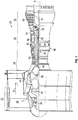
- FIG. 1 schematically illustrates a gas turbine engine 20.
- the gas turbine engine 20 is disclosed herein as a two-spool turbofan that generally incorporates a fan section 22, a compressor section 24, a combustor section 26 and a turbine section 28.
- Alternative engines might include an augmentor section (not shown) among other systems or features.
- the fan section 22 drives air along a bypass flow path B in a bypass duct, while the compressor section 24 drives air along a core flow path C for compression and communication into the combustor section 26 then expansion through the turbine section 28.
- the exemplary engine 20 generally includes a low speed spool 30 and a high speed spool 32 mounted for rotation about an engine central longitudinal axis A relative to an engine static structure 36 via several bearing systems 38. It should be understood that various bearing systems 38 at various locations may alternatively or additionally be provided, and the location of bearing systems 38 may be varied as appropriate to the application.
- the low speed spool 30 generally includes an inner shaft 40 that interconnects a fan 42, a low pressure compressor 44 and a low pressure turbine 46.
- the inner shaft 40 is connected to the fan 42 through a speed change mechanism, which in exemplary gas turbine engine 20 is illustrated as a geared architecture 48 to drive the fan 42 at a lower speed than the low speed spool 30.
- the high speed spool 32 includes an outer shaft 50 that interconnects a high pressure compressor 52 and high pressure turbine 54.
- a combustor 56 is arranged in exemplary gas turbine 20 between the high pressure compressor 52 and the high pressure turbine 54.
- An engine static structure 36 is arranged generally between the high pressure turbine 54 and the low pressure turbine 46.
- the engine static structure 36 further supports bearing systems 38 in the turbine section 28.
- the inner shaft 40 and the outer shaft 50 are concentric and rotate via bearing systems 38 about the engine central longitudinal axis A which is collinear with their longitudinal axes.
- each of the positions of the fan section 22, compressor section 24, combustor section 26, turbine section 28, and fan drive gear system 48 may be varied.
- gear system 48 may be located aft of combustor section 26 or even aft of turbine section 28, and fan section 22 may be positioned forward or aft of the location of gear system 48.
- the engine 20 in one example is a high-bypass geared aircraft engine.
- the engine 20 bypass ratio is greater than about six (6), with an example embodiment being greater than about ten (10)
- the geared architecture 48 is an epicyclic gear train, such as a planetary gear system or other gear system, with a gear reduction ratio of greater than about 2.3
- the low pressure turbine 46 has a pressure ratio that is greater than about five.
- the engine 20 bypass ratio is greater than about ten (10:1)
- the fan diameter is significantly larger than that of the low pressure compressor 44
- the low pressure turbine 46 has a pressure ratio that is greater than about five 5:1.
- Low pressure turbine 46 pressure ratio is pressure measured prior to inlet of low pressure turbine 46 as related to the pressure at the outlet of the low pressure turbine 46 prior to an exhaust nozzle.
- the geared architecture 48 may be an epicycle gear train, such as a planeteray gear system or other gear system, with a gear reduction ratio of greater than about 2.3:1. It should be understood, however, that the above parameters are only exemplary of one embodiment of a geared architecture engine and that the present disclosure is applicable to other gas turbine engines including direct drive turbofans.
- the fan section 22 of the engine 20 is designed for a particular flight condition--typically cruise at about 0.8Mach and about 35,000 feet (10,688 meters).
- 'TSFC' Thrust Specific Fuel Consumption
- Low fan pressure ratio is the pressure ratio across the fan blade alone, without a Fan Exit Guide Vane (“FEGV”) system.
- the low fan pressure ratio as disclosed herein according to one non-limiting embodiment is less than about 1.45.
- Low corrected fan tip speed is the actual fan tip speed in ft/sec divided by an industry standard temperature correction of [(Tram °R)/(518.7 °R)] 0.5 .
- the "Low corrected fan tip speed” as disclosed herein according to one non-limiting embodiment is less than about 1150 ft/second (350.5 m/sec).
- the turbine section 28 includes turbine discs 70 that each rotate about the axis A.
- the turbine section may include a plurality of stages each having a plurality of turbine blades mounted to respective turbine disk of each stage.
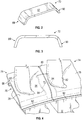
- FIG. 2 illustrates a non-limiting perspective view of a damper seal or damper 72 for installation under platforms of adjacent turbine blades to reduce the vibratory response and provide frictional damping between the turbine blades as well as sealing the mate-face gap between blades.
- dampers may be made of sheet metal and conform to the underside of the platform when subjected to centrifugal loads in a high temperature environment due to their lack of stiffness out-of-plane.
- FIG. 3 is a side view of the damper seal or damper 72 illustrated in FIG. 2 .
- the damper seal or damper 72 may also be formed by direct metal laser sintering. Other manufacturing methods are possible.
- the damper seal 72 may be ductile enough to conform to a lower surface of the platform of the turbine blade. In one example, the damper seal 72 is substantially c-shaped.
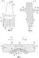
- FIG. 4 a top perspective view of the damper seal 72 installed in adjacent turbine blades 74 is provided.
- the damper seal 72 is located in a neck cavity 76 of the turbine blades 74.
- the neck cavity 76 is defined as being located below the platform 78 of the turbine blade 74 and above the turbine disk the blades 74 are secured to.
- the damper seal 72 spans a space 80 between adjacent platforms 78 of adjacent turbine blades 74 to provide both damping and sealing and prevent the leakage of the cooling air from the cavity 76.
- the damper seal 72 imposes a normal load on the adjacent turbine blades 74 due to centrifugal force. The resulting frictional force created by the normal load produces damping to reduce a vibratory response.
- the damper seal 72 prevents the cooling air in the neck cavity 76 from leaking into the hot flow gas path between airfoils 82 of the turbine blades 74.
- the damper seal 72 is located under the platforms 78 of adjacent turbine blades 74 and spans the space 80 between the platforms 78.
- a bevel or chamfer 84 is located at lateral edges 86 and 88 of the platform 78.
- the bevel or chamfer 84 may have any configuration (e.g, linear, curved, combinations thereof, etc.).
- the bevels or chamfers define a recess or recessed area 85 for receipt of at least a portion of the damper seal 72 therein.
- a top portion 87 of the damper seal 72 is received in recess or recessed area 85.
- the top portion 87 extends between a first end portion 89 and an opposing opposite second end portion 90. As illustrated, the first end portion 89 and the second end portion 90 extend towards a root 92 of the turbine blade 74 when the damper seal 72 is located in the cavity 76.
- the chamfers or bevels 84 of adjacent platforms 78 are illustrated adjacent to each other, which corresponds to when the platforms 78 of the turbine blades 74 are secured to the disc 70.
- the chamfer or bevel 84 of edge 86 runs under a suction side 94 of the platform 78 while the chamfer or bevel 84 of edge 88 runs under a pressure side 96 of the platform 78.
- the edges 86 and 88 are located on opposite sides of the platform 78 such that adjacent bevels or chamfers 84 define the recess or cavity 85 into which the top portion 87 of the damper seal 72 is received.
- the damper seal 72 is wedged into the recess or cavity 98 as illustrated in FIG. 7 such that the top portion 87 of the damper seal 72 is curved.
- top portion 87 By wedging the top portion 87 into the recess or cavity 98, a radial component is added to the contact surface 87 of the damper seal 72.
- the curved surface of top portion 87 which is caused by the heat and centripetal forces applied thereto, is adjacent to the surfaces of recess 85 formed by the adjacent chamfers 84.
- This radial component is illustrated by curved line 99. This radial component improves dampening in the radial direction between the adjacent platforms 78 illustrated by arrow 101.
- the chamfers or bevels also restrain movement of the damper seal 72 in the directions of arrows 103. Accordingly, the platforms 78 with chamfered edges provide damping in a radial direction as well as preventing movement of the damper seal in a tangential direction(s) 103.
- the bevel or chamfer 84 on the platform edge may be formed into existing or new designs.
- the bevel or chamfer 84 may be machined into a platform 78 that already has been formed or alternatively the bevel or chamfer 84 may be included into a cast used to form new platforms 78.
- a bevel or chamfer 84 at peripheral edges 86, 88 of the platform 78 there is no need for a special damper seal design.
- the use of a bevel or chamfer can be particularly useful in the aftermarket as a way of correcting unintended damper operation.
- an existing platform 78 can be machined to have a chamfer or bevel 84 located at a peripheral edge.
- a bevel or chamfer 84 extending over a portion or the extent of both the pressure side and suction side of the platform edges is provided.
- the beveled edge provides a wedge into which a seal damper or damper seal 72 plastically deforms under centrifugal loading and high temperature.
- the beveled edge provides a contact surface between the underside of the platforms and the seal damper or damper seal 72 with a radial and tangential component so that the system is effective in suppressing both radial and tangential vibration.
- Various embodiments of the present disclosure provide improved damper performance for blades that exhibit radial vibration.
- existing designs can be easily modified to incorporate the chamfered edge design. As such, a potential aftermarket fix to correct excessive damper deformation is provided. Still further, the overall weight of the platform 78 is reduced due to the removal of material to create the chamfer or bevel 84.
- a device that restrains the damper seal 72 from sliding toward the suction side of the pocket 76 or the pressure side of the pocket 76 when it is subject to tangential dynamic forces or rotational forces (e.g. induced by the orientation of the pocket (or broach angle) relative to the axis of rotation).
- This design feature (e.g., chamfer or bevel 84) allows the potential elimination of weight increasing damper restraint devices. It can make new and current damper designs more effective without modifying the damper itself, and with only a minimal change to the blade platform that can be readily cast in.
- the feature can also be formed through some grinding or machining technique to remove materials from the platform to create the bevel or chamfer or the bevel or chamfer can be can cast in.
Landscapes
- Engineering & Computer Science (AREA)
- Mechanical Engineering (AREA)
- General Engineering & Computer Science (AREA)
- Structures Of Non-Positive Displacement Pumps (AREA)
Applications Claiming Priority (1)
| Application Number | Priority Date | Filing Date | Title |
|---|---|---|---|
| US15/397,501 US20180187558A1 (en) | 2017-01-03 | 2017-01-03 | Blade platform with chamfer |
Publications (1)
| Publication Number | Publication Date |
|---|---|
| EP3342984A1 true EP3342984A1 (de) | 2018-07-04 |
Family
ID=60923378
Family Applications (1)
| Application Number | Title | Priority Date | Filing Date |
|---|---|---|---|
| EP18150231.1A Withdrawn EP3342984A1 (de) | 2017-01-03 | 2018-01-03 | Laufschaufel, zugehöriges gasturbinentriebwerk und verfahren zur dämpfung von vibrationen zwischen angrenzenden laufschaufeln |
Country Status (2)
| Country | Link |
|---|---|
| US (1) | US20180187558A1 (de) |
| EP (1) | EP3342984A1 (de) |
Families Citing this family (8)
| Publication number | Priority date | Publication date | Assignee | Title |
|---|---|---|---|---|
| US10662784B2 (en) | 2016-11-28 | 2020-05-26 | Raytheon Technologies Corporation | Damper with varying thickness for a blade |
| US10677073B2 (en) | 2017-01-03 | 2020-06-09 | Raytheon Technologies Corporation | Blade platform with damper restraint |
| US10731479B2 (en) | 2017-01-03 | 2020-08-04 | Raytheon Technologies Corporation | Blade platform with damper restraint |
| US10907491B2 (en) * | 2017-11-30 | 2021-02-02 | General Electric Company | Sealing system for a rotary machine and method of assembling same |
| US11377967B2 (en) | 2019-12-06 | 2022-07-05 | Raytheon Technologies Corporation | Pre-formed faceted turbine blade damper seal |
| US11815017B2 (en) * | 2020-04-16 | 2023-11-14 | Rtx Corporation | Fan blade platform for gas turbine engine |
| CN114382549B (zh) * | 2020-10-21 | 2024-04-23 | 中国航发商用航空发动机有限责任公司 | 涡轮和航空发动机 |
| US12228032B1 (en) * | 2023-10-17 | 2025-02-18 | Rtx Corporation | Metallic seal |
Citations (3)
| Publication number | Priority date | Publication date | Assignee | Title |
|---|---|---|---|---|
| US3709631A (en) * | 1971-03-18 | 1973-01-09 | Caterpillar Tractor Co | Turbine blade seal arrangement |
| US4183720A (en) * | 1978-01-03 | 1980-01-15 | The United States Of America As Represented By The Secretary Of The Air Force | Composite fan blade platform double wedge centrifugal seal |
| FR2927357A1 (fr) * | 2008-02-12 | 2009-08-14 | Snecma Sa | Dispositif d'amortissement des vibrations entre deux aubes de roue aubagee de turbomachine |
Family Cites Families (1)
| Publication number | Priority date | Publication date | Assignee | Title |
|---|---|---|---|---|
| US9822644B2 (en) * | 2015-02-27 | 2017-11-21 | Pratt & Whitney Canada Corp. | Rotor blade vibration damper |
-
2017
- 2017-01-03 US US15/397,501 patent/US20180187558A1/en not_active Abandoned
-
2018
- 2018-01-03 EP EP18150231.1A patent/EP3342984A1/de not_active Withdrawn
Patent Citations (3)
| Publication number | Priority date | Publication date | Assignee | Title |
|---|---|---|---|---|
| US3709631A (en) * | 1971-03-18 | 1973-01-09 | Caterpillar Tractor Co | Turbine blade seal arrangement |
| US4183720A (en) * | 1978-01-03 | 1980-01-15 | The United States Of America As Represented By The Secretary Of The Air Force | Composite fan blade platform double wedge centrifugal seal |
| FR2927357A1 (fr) * | 2008-02-12 | 2009-08-14 | Snecma Sa | Dispositif d'amortissement des vibrations entre deux aubes de roue aubagee de turbomachine |
Also Published As
| Publication number | Publication date |
|---|---|
| US20180187558A1 (en) | 2018-07-05 |
Similar Documents
| Publication | Publication Date | Title |
|---|---|---|
| EP3342984A1 (de) | Laufschaufel, zugehöriges gasturbinentriebwerk und verfahren zur dämpfung von vibrationen zwischen angrenzenden laufschaufeln | |
| US10731479B2 (en) | Blade platform with damper restraint | |
| US10677073B2 (en) | Blade platform with damper restraint | |
| EP2836682B1 (de) | Dämpfungsdichtung für eine turbinenschaufel | |
| EP3327253A1 (de) | Dämpfer mit variierender dicke für eine schaufel | |
| EP3054088B1 (de) | Gasturbinenrotorscheibenauswuchtung | |
| EP3093445A1 (de) | Schaufelprofil, zugehörige leitschaufel und herstellungsverfahren | |
| EP3088676B1 (de) | Gasturbinenmotordämpfungsvorrichtung | |
| US20180106153A1 (en) | Blades and blade dampers for gas turbine engines | |
| US11230939B2 (en) | Vane seal system and seal therefor | |
| EP3832072A1 (de) | Vorgeformte facettierte dämpferdichtung für turbinenschaufeln | |
| EP3447250B1 (de) | Schaufelplattform mit dämpferrückhaltung | |
| US10641109B2 (en) | Mass offset for damping performance | |
| EP3047107B1 (de) | Plattformdichtungskühlung für gasturbinentriebwerkskomponenten | |
| EP2998514B1 (de) | Umgekehrt einbaubare laufschaufelplattformdichtung | |
| EP3246535A1 (de) | Turbinenleitschaufel mit versteifungsrippen für die deckbandschienen | |
| EP3109403B1 (de) | Umkehrbare schaufelrotordichtung mit vorsprüngen | |
| US10119410B2 (en) | Vane seal system having spring positively locating seal member in axial direction |
Legal Events
| Date | Code | Title | Description |
|---|---|---|---|
| PUAI | Public reference made under article 153(3) epc to a published international application that has entered the european phase |
Free format text: ORIGINAL CODE: 0009012 |
|
| STAA | Information on the status of an ep patent application or granted ep patent |
Free format text: STATUS: THE APPLICATION HAS BEEN PUBLISHED |
|
| AK | Designated contracting states |
Kind code of ref document: A1 Designated state(s): AL AT BE BG CH CY CZ DE DK EE ES FI FR GB GR HR HU IE IS IT LI LT LU LV MC MK MT NL NO PL PT RO RS SE SI SK SM TR |
|
| AX | Request for extension of the european patent |
Extension state: BA ME |
|
| STAA | Information on the status of an ep patent application or granted ep patent |
Free format text: STATUS: REQUEST FOR EXAMINATION WAS MADE |
|
| 17P | Request for examination filed |
Effective date: 20181221 |
|
| RBV | Designated contracting states (corrected) |
Designated state(s): AL AT BE BG CH CY CZ DE DK EE ES FI FR GB GR HR HU IE IS IT LI LT LU LV MC MK MT NL NO PL PT RO RS SE SI SK SM TR |
|
| STAA | Information on the status of an ep patent application or granted ep patent |
Free format text: STATUS: THE APPLICATION IS DEEMED TO BE WITHDRAWN |
|
| 18D | Application deemed to be withdrawn |
Effective date: 20190105 |