EP3342726A1 - Packaging for receiving a filling material - Google Patents
Packaging for receiving a filling material Download PDFInfo
- Publication number
- EP3342726A1 EP3342726A1 EP16207345.6A EP16207345A EP3342726A1 EP 3342726 A1 EP3342726 A1 EP 3342726A1 EP 16207345 A EP16207345 A EP 16207345A EP 3342726 A1 EP3342726 A1 EP 3342726A1
- Authority
- EP
- European Patent Office
- Prior art keywords
- gasket
- collar
- ring body
- lid
- flap
- Prior art date
- Legal status (The legal status is an assumption and is not a legal conclusion. Google has not performed a legal analysis and makes no representation as to the accuracy of the status listed.)
- Withdrawn
Links
- 239000000463 material Substances 0.000 title claims abstract description 41
- 238000004806 packaging method and process Methods 0.000 title claims abstract description 32
- 238000007789 sealing Methods 0.000 claims abstract description 42
- 239000013013 elastic material Substances 0.000 claims abstract description 4
- 239000011888 foil Substances 0.000 claims description 13
- 230000007613 environmental effect Effects 0.000 claims description 8
- ZKQDCIXGCQPQNV-UHFFFAOYSA-N Calcium hypochlorite Chemical compound [Ca+2].Cl[O-].Cl[O-] ZKQDCIXGCQPQNV-UHFFFAOYSA-N 0.000 claims description 3
- 239000007844 bleaching agent Substances 0.000 claims description 3
- 239000002537 cosmetic Substances 0.000 claims description 2
- 238000004519 manufacturing process Methods 0.000 description 5
- 230000000694 effects Effects 0.000 description 4
- 238000006073 displacement reaction Methods 0.000 description 3
- 238000001746 injection moulding Methods 0.000 description 3
- 239000002184 metal Substances 0.000 description 3
- 229910052751 metal Inorganic materials 0.000 description 3
- 239000004033 plastic Substances 0.000 description 3
- 229920003023 plastic Polymers 0.000 description 3
- -1 polypropylene Polymers 0.000 description 3
- 239000000843 powder Substances 0.000 description 3
- 239000004743 Polypropylene Substances 0.000 description 2
- 238000000071 blow moulding Methods 0.000 description 2
- 230000006835 compression Effects 0.000 description 2
- 238000007906 compression Methods 0.000 description 2
- 229920001155 polypropylene Polymers 0.000 description 2
- 229920002725 thermoplastic elastomer Polymers 0.000 description 2
- 239000004698 Polyethylene Substances 0.000 description 1
- 238000005054 agglomeration Methods 0.000 description 1
- 230000002776 aggregation Effects 0.000 description 1
- 239000004411 aluminium Substances 0.000 description 1
- 229910052782 aluminium Inorganic materials 0.000 description 1
- XAGFODPZIPBFFR-UHFFFAOYSA-N aluminium Chemical compound [Al] XAGFODPZIPBFFR-UHFFFAOYSA-N 0.000 description 1
- 238000005452 bending Methods 0.000 description 1
- 230000000903 blocking effect Effects 0.000 description 1
- 230000001419 dependent effect Effects 0.000 description 1
- 229920001971 elastomer Polymers 0.000 description 1
- 239000000806 elastomer Substances 0.000 description 1
- 239000007769 metal material Substances 0.000 description 1
- 229920000573 polyethylene Polymers 0.000 description 1
- 229920001296 polysiloxane Polymers 0.000 description 1
- 239000000243 solution Substances 0.000 description 1
- 239000012815 thermoplastic material Substances 0.000 description 1
Images


Classifications
-
- B—PERFORMING OPERATIONS; TRANSPORTING
- B65—CONVEYING; PACKING; STORING; HANDLING THIN OR FILAMENTARY MATERIAL
- B65D—CONTAINERS FOR STORAGE OR TRANSPORT OF ARTICLES OR MATERIALS, e.g. BAGS, BARRELS, BOTTLES, BOXES, CANS, CARTONS, CRATES, DRUMS, JARS, TANKS, HOPPERS, FORWARDING CONTAINERS; ACCESSORIES, CLOSURES, OR FITTINGS THEREFOR; PACKAGING ELEMENTS; PACKAGES
- B65D53/00—Sealing or packing elements; Sealings formed by liquid or plastics material
- B65D53/02—Collars or rings
-
- B—PERFORMING OPERATIONS; TRANSPORTING
- B65—CONVEYING; PACKING; STORING; HANDLING THIN OR FILAMENTARY MATERIAL
- B65D—CONTAINERS FOR STORAGE OR TRANSPORT OF ARTICLES OR MATERIALS, e.g. BAGS, BARRELS, BOTTLES, BOXES, CANS, CARTONS, CRATES, DRUMS, JARS, TANKS, HOPPERS, FORWARDING CONTAINERS; ACCESSORIES, CLOSURES, OR FITTINGS THEREFOR; PACKAGING ELEMENTS; PACKAGES
- B65D43/00—Lids or covers for rigid or semi-rigid containers
- B65D43/14—Non-removable lids or covers
- B65D43/16—Non-removable lids or covers hinged for upward or downward movement
- B65D43/162—Non-removable lids or covers hinged for upward or downward movement the container, the lid and the hinge being made of one piece
-
- B—PERFORMING OPERATIONS; TRANSPORTING
- B65—CONVEYING; PACKING; STORING; HANDLING THIN OR FILAMENTARY MATERIAL
- B65D—CONTAINERS FOR STORAGE OR TRANSPORT OF ARTICLES OR MATERIALS, e.g. BAGS, BARRELS, BOTTLES, BOXES, CANS, CARTONS, CRATES, DRUMS, JARS, TANKS, HOPPERS, FORWARDING CONTAINERS; ACCESSORIES, CLOSURES, OR FITTINGS THEREFOR; PACKAGING ELEMENTS; PACKAGES
- B65D51/00—Closures not otherwise provided for
- B65D51/18—Arrangements of closures with protective outer cap-like covers or of two or more co-operating closures
- B65D51/20—Caps, lids, or covers co-operating with an inner closure arranged to be opened by piercing, cutting, or tearing
-
- B—PERFORMING OPERATIONS; TRANSPORTING
- B65—CONVEYING; PACKING; STORING; HANDLING THIN OR FILAMENTARY MATERIAL
- B65D—CONTAINERS FOR STORAGE OR TRANSPORT OF ARTICLES OR MATERIALS, e.g. BAGS, BARRELS, BOTTLES, BOXES, CANS, CARTONS, CRATES, DRUMS, JARS, TANKS, HOPPERS, FORWARDING CONTAINERS; ACCESSORIES, CLOSURES, OR FITTINGS THEREFOR; PACKAGING ELEMENTS; PACKAGES
- B65D85/00—Containers, packaging elements or packages, specially adapted for particular articles or materials
- B65D85/70—Containers, packaging elements or packages, specially adapted for particular articles or materials for materials not otherwise provided for
-
- F—MECHANICAL ENGINEERING; LIGHTING; HEATING; WEAPONS; BLASTING
- F16—ENGINEERING ELEMENTS AND UNITS; GENERAL MEASURES FOR PRODUCING AND MAINTAINING EFFECTIVE FUNCTIONING OF MACHINES OR INSTALLATIONS; THERMAL INSULATION IN GENERAL
- F16J—PISTONS; CYLINDERS; SEALINGS
- F16J15/00—Sealings
- F16J15/02—Sealings between relatively-stationary surfaces
- F16J15/021—Sealings between relatively-stationary surfaces with elastic packing
- F16J15/022—Sealings between relatively-stationary surfaces with elastic packing characterised by structure or material
- F16J15/024—Sealings between relatively-stationary surfaces with elastic packing characterised by structure or material the packing being locally weakened in order to increase elasticity
- F16J15/025—Sealings between relatively-stationary surfaces with elastic packing characterised by structure or material the packing being locally weakened in order to increase elasticity and with at least one flexible lip
-
- B—PERFORMING OPERATIONS; TRANSPORTING
- B65—CONVEYING; PACKING; STORING; HANDLING THIN OR FILAMENTARY MATERIAL
- B65D—CONTAINERS FOR STORAGE OR TRANSPORT OF ARTICLES OR MATERIALS, e.g. BAGS, BARRELS, BOTTLES, BOXES, CANS, CARTONS, CRATES, DRUMS, JARS, TANKS, HOPPERS, FORWARDING CONTAINERS; ACCESSORIES, CLOSURES, OR FITTINGS THEREFOR; PACKAGING ELEMENTS; PACKAGES
- B65D2251/00—Details relating to container closures
- B65D2251/0003—Two or more closures
- B65D2251/0006—Upper closure
- B65D2251/0018—Upper closure of the 43-type
- B65D2251/0021—Upper closure of the 43-type of the B65D43/16-type
-
- B—PERFORMING OPERATIONS; TRANSPORTING
- B65—CONVEYING; PACKING; STORING; HANDLING THIN OR FILAMENTARY MATERIAL
- B65D—CONTAINERS FOR STORAGE OR TRANSPORT OF ARTICLES OR MATERIALS, e.g. BAGS, BARRELS, BOTTLES, BOXES, CANS, CARTONS, CRATES, DRUMS, JARS, TANKS, HOPPERS, FORWARDING CONTAINERS; ACCESSORIES, CLOSURES, OR FITTINGS THEREFOR; PACKAGING ELEMENTS; PACKAGES
- B65D2251/00—Details relating to container closures
- B65D2251/0003—Two or more closures
- B65D2251/0068—Lower closure
- B65D2251/0093—Membrane
Definitions
- the invention relates to a packaging by which a filling material can be received and securely transported as well as stored over extended periods of time.
- WO 2009/147194 A2 discloses a packaging suitable for storing a hygroscopic powder, wherein an opening of a container for storing the hygroscopic powder can be sealed by means of a metal foil glued to a front face of a collar of the container which borders the opening.
- US 8,511,499 B2 discloses a packaging suitable for storing a powder, wherein an opening of a container is sealed by a sealing foil which is pressed against a rim of the opening by means of a collar.
- the collar is clamped to the container and comprises a flexible gasket connected to the rigid collar. The gasket can be pressed against the rim by means of a lid in closed state for sealing the opening
- a packaging for receiving a filling material comprising a container for storing the filling material, wherein the container comprises a collar for bordering an opening for providing access to the filling material, wherein the collar comprises an undercut running in circumferential direction, a lid for covering the opening in closed state and a gasket made from an elastic material for sealing the opening, wherein the gasket comprises a ring body for surrounding the opening, a nose protruding mainly radially from the ring body, wherein the gasket encompasses the undercut by means of the nose for connecting the gasket to the collar in a sealing manner, and a flap protruding mainly radially from the ring body, wherein the flap is adapted to seal the lid in closed state of the lid.
- the gasket may provide a moisture-proof sealing with the container via the collar of the container.
- the nose and/or the ring body may be pressed against the collar along the whole circumference of the collar with a sufficient contact force. Due to the elastic material of the gasket the nose and/or the ring body may be sufficiently deformed for providing the intended contact force. The nose and/or the ring body may be sufficiently stretched or compressed for providing a sufficient corresponding resilient force.
- the geometry of the gasket can be easily chosen in respect to the geometry of the collar for providing a specific minimum deformation and in turn a definite minimum contact force between the gasket and the collar of the container. This minimum contact force can be guaranteed easily even when low requirements in respect to fabrication tolerances apply.
- the lid contacts the flap of the gasket in the closed state of the lid.
- the lid may be pressed against the gasket in the closed state so that a sufficient contact pressure, particularly for a moisture-proof sealing, may be provided.
- the filling material inside the container may be sufficiently protected for environmental impacts, for instance humidity or other influences.
- the container and the lid provide together with the gasket an enclosed volume for the filling material protected from the environment.
- the lid may be pressed against the gasket for providing a sufficient sealing. Particularly the lid is pressed against the flap, preferably only against the flap, in the closed state.
- the flap may be biased and may provide a sufficient resilient force.
- the flap may compensate a displacement of the lid relative to the collar of the container and the gasket.
- the flap may be bent more or less depending on the displacement of the lid and the relative position of each part of the flap to a side wall of the lid.
- a higher or a lower resilient force may be provided from the flap depending on the distance of the side wall of the lid to the ring body of the gasket at each part of the gasket and the gap between the side wall and the ring body bridged by the flap.
- the minimum contact force between the flap and the lid and/or the minimum contact force between the nose and/or the ring body and the collar can be sufficient for providing a specific quality of the sealing, particularly a moisture-proof sealing.
- the three-dimensional design of the gasket allows a tight sealing as well as an elastic compensation of tolerances, so that a good and cost-efficient sealing of the packaging is enabled.
- the nose and/or the ring body may contact the collar of the container in a two-dimensional manner so that a large contact area is provided.
- the sealing effect between the gasket and the collar may be increased.
- the side wall of the lid may be arranged mainly in parallel to the ring body of the gasket in the closed state of the lid. In the alternate the side wall of the lid may be arranged inclined with respect to the ring body of the gasket in the closed state of the lid. Particularly the side wall and the ring body may border a mainly funnel-shaped gap between the side wall and the ring body in the closed state of the lid. During the closing movement of the lid the sealing force may increase until its maximum in the closed state.
- a top part of the lid may abut the ring body of the gasket so that the ring body provide a stop for the closing movement of the lid.
- a defined maximum closed state can be provided, when the top part of the lid meets an upper front face of the ring body.
- the lid applies a force to the gasket pointing at least with a portion in radial direction so that the lid may press the ring body of the gasket against the collar, preferably when the ring body is provided between the collar and the side wall of the lid in radial direction.
- the collar is arranged radially inwards to the ring body of the gasket.
- the side wall of the lid may be arranged radially inwards to the ring body of the gasket, so that the side wall may provide a plug inserted into the gasket and/or the opening.
- the container particularly together with the collar, may be produced from a plastic material, particularly by blow molding or by plastic injection molding.
- the container may be made from a thermoplastic material, particularly polypropylene.
- the lid may be connected to the container directly or indirectly.
- the lid is one-piece with the container and connected to the container via a film hinge.
- the packaging may be designed further as disclosed in WO 2009/147194 A2 whose content is herewith incorporated as part of the invention.
- a closure part surrounding the collar is connected to the container, wherein the gasket is fastened, particularly clamped, between the collar and the closure part.
- the frame-like closure part may be mounted after the gasket is arranged around the collar.
- the gasket may comprise a protruding part protruding radially outwards, which may be arranged between the container and the closure part in axial direction so that a loss-proof connection of the gasket is provided.
- the gasket may be fastened by means of the closure part due to a positive fit and/or a friction fit.
- a press fit is provided between the rigid closure part and the elastic gasket so that the gasket may be deformed by the closure part and provides a corresponding increased sealing force against the collar.
- the lid may be centered by means of the closure part in the closed state. If so, the lid may be releasably clamped to the closure part in the closed state, so that the lid is secured against unintentional opening.
- the flap protrudes mainly radially outwards from the ring body, wherein the flap is bent by the lid in the closed state.
- the flap may contact the side wall in a two-dimensional manner so that a large contact area is provided. A pure line contact may be prevented.
- the sealing effect between the gasket and the lid may be increased.
- the lid may comprise a mainly U-shaped cross section comprising a top part and a circumferential side wall protruding from the top part. The lid may cover not only the opening but also the collar and the gasket so that an appealing design of the packaging in the closed state may be provided.
- the ring body comprises a pocket for receiving the flap in the maximum bent state, wherein particularly a contact area of the flap for contacting the lid and an outer lateral area of the ring body outside the pocket are arranged mainly flush in the maximum bent state of the flap.
- the lid may also meet the remaining ring body, particularly a protruding part of the ring body, and/or the frame-like closure part which fastens, particularly clamps, the ring body and/or the nose to the collar. In this state a further movement of the lid towards the collar at this place may be blocked by the gasket since the compressed material of the gasket finds no place to evade and/or the rigid closure part.
- a further compression of the gasket at this place may be blocked and a resistance force against a further movement of the lid towards the collar may significantly increase at this place.
- a contact area of the flap for contacting the lid transits into an upper front face of the ring body.
- a part of the ring body protruding upwards from the upper end of the flap is prevented. If so, a stop function for blocking a closing movement of the lid can be provided at the level of the upper end of the flap.
- a protruding part is not necessary for providing the stop function.
- the stop function may be provided by the closure part and/or protruding part of the gasket protruding radially outwards.
- the protruding part of the gasket may be arranged below the flap. The dimensions of the gasket as well as the required material for manufacturing the gasket can be kept low.
- the gasket is made from an elastomer material, particularly silicone, thermoplastic elastomer or rubber. Due to this material the gasket can be deformed by means of the closing lid and may provide a sufficient resilient force for providing a tight sealing.
- an elastomer material particularly silicone, thermoplastic elastomer or rubber. Due to this material the gasket can be deformed by means of the closing lid and may provide a sufficient resilient force for providing a tight sealing.
- the gasket comprises a hardness h in Shore A according to DIN ISO 7619-1:2010 at 23°C of 5 ⁇ h ⁇ 90.
- This hardness allows a sufficient deforming of the gasket when the lid is closed.
- the gasket may provide a sufficient counterforce against the deformation for providing a contact force which leads to a tight sealing.
- the nose transits into a lower front face of the ring body. A part of the ring body protruding downwards from the lower end of the nose is prevented.
- the dimensions of the gasket as well as the required material for manufacturing the gasket can be kept low.
- the nose protrudes mainly radially inwards from the ring body, wherein the undercut is provided at the radial outer lateral area of the collar.
- the opening of the container may be bordered by the collar only.
- the presence of the gasket may not reduce the accessibility of the inner volume of the container and the filling material inside the container. Further the gasket may be stretched to a larger average diameter for connecting the gasket to the collar. A quite high contact force of the gasket to the radial outer face of the collar may be provided leading to a corresponding tight sealing.
- the collar comprises a front face pointing away from the remaining container, wherein a sealing foil is connected to the front face.
- the opening may be sealed in addition by means of the sealing foil.
- the foil may be glued and/or welded to the front face.
- the container may preferably receive hydrophilic materials and/or hygroscopic materials, for example bleaching powder.
- the foil may protect the filling material from environmental influences until first use of the filing material so that no humidity may enter the container and contact the filling material.
- the foil may be made from a metal material, particularly comprising aluminium. Particularly after the disposal of the sealing foil during the first removal of a part of the filling material the gasket may protect the remaining filling material for environmental influences, like humidity.
- the collar comprises a front face pointing away from the remaining container, wherein the ring body comprise a stop face for meeting the front face.
- the axial relative position of the gasket to the collar can be given by the stop meeting the collar.
- the axial relative position of the gasket to the collar is not or not only given by the nose encompassing the undercut of the collar. This allows a relative position of the nose where the nose is pressed against the undercut with a specific contact force by which a sufficient tight sealing is provided.
- the undercut is press fitted between the nose and the stop face.
- the material of the collar providing the undercut may be clamped between the nose and the stop face. Due to the press fit a high contact force between the gasket and the collar as well as a corresponding tight sealing may be provided.
- the undercut is provided by a groove provided in the collar.
- the groove may be larger than the nose and particularly provides a clearance fit with the nose so that the nose may be easily inserted into the groove.
- the groove may provide a press fit with the nose so that a sufficient contact force is already provided when the nose is pressed into the groove.
- One axial side of the groove may provide an axial face of the undercut, wherein the opposite side may block a too large displacement of the gasket with respect to the collar.
- the base face of the groove may be located spaced to a tip of the nose so that the nose may deform into the groove, if required.
- a material sensitive to the environmental atmosphere is provided inside the container, wherein particularly the material comprises or consists of a cosmetic product, particularly a bleaching powder. Due to the tight sealing such kind of a filling material may be stored inside the container without the risk that the filling material is affected by environmental influences. For example, an agglomeration of a hygroscopic material due to environmental humidity may be prevented.
- the ring body, the nose and the flap are one-piece for forming the gasket.
- the gasket may be produced one-piece by injection molding or the like so that it is not necessary to connect different separated parts to one common gasket. The manufacturing costs may be kept low.
- the packaging 10 as illustrated in fig. 1 comprises a container 12 and a significantly smaller additional compartment 14.
- the container 12 can be manufactured from polyethylene by blow moulding.
- the additional compartment 14 can in particular be manufactured from polypropylene by plastic injection moulding.
- the additional compartment 14 may comprises a spoon for removing a part of the filling material.
- a lid 16 is connected to the additional compartment 14 via a film hinge.
- the additional compartment 14 may be connected to the container as described in WO 2009/147194 A2 so that in turn the lid 16 is also connected to the container 12.
- the container comprises a collar 18 bordering an opening 20 for providing access to the inside of the container 12.
- the opening 20 may by sealed by means of a metal sealing foil 22 glued to the collar.
- a gasket 24 as illustrated in fig.
- the lid 16 and the container 12 are distributed over different parts.
- the lid may be one-piece with the container, wherein particularly the lid 16 is connected to the container via a film hinge. If so, the additional compartment 14 may be omitted or be also one-piece with the container 12 in the alternate embodiment.
- the gasket 24 as illustrated in fig. 2 and fig. 3 comprises a ring body 26 which can be deformed, particularly stretched, and pressed by means of its resilient force onto the collar.
- the form of the ring body 26 may correspond mainly to a radial face of the collar 18.
- a nose 28 protrudes from the ring body 26 radially inwards for being received into a groove 30 of the collar 18 so that the gasket 24 encompasses an undercut 32 of the collar as illustrated in fig. 4 .
- the nose 28 transits into a lower front face 34 of the ring body 26.
- the ring body 26 further comprises a stop face 36 arranged opposite to the nose 28.
- the stop face 36 may meet a front face 38 of the collar 18 for providing a definite relative axial position of the gasket 24 to the collar 18 and preferably for clamping a protruding rim 40 of the collar 18 between the stop face 36 and the nose 28.
- the protruding rim 40 provides the undercut 32 of the collar.
- a flap 42 protrudes from the ring body 26 particularly radially outwards.
- the flap 42 transits into an upper front face 50 of the ring body 26.
- the lid 16 When the lid 16 is closed as illustrated in fig. 4 the lid 18 may meet a contact area 52 of the flap 42 and bend the flap 42 towards the ring body 26 so that an increasing resilient force is provided by the bent flap 42.
- the contact area 52 In the alternate the contact area 52 may be nearly linear, so that a frictional relative movement of the lid 16 relative to the flap 42 may be reduced.
- the lid 16 may comprise a top part 44 from which a side wall 46 may protrude for providing a mainly U-shaped cross section.
- the side wall 46 may aligned orthogonal to the top part 44 or inclined with respect to the top part running towards or particularly away from the collar 18 in the closed state. Particularly the side wall 46 only bends the flap 42.
- the ring body 26 may comprise a pocket 48 into which the flap 42 may be bent.
- the contact area 52 of the flap and an outer lateral area 54 of the ring body may or may not arranged mainly flush in the maximum bent state of the flap 42.
- a frame-like closure part 56 may be connected to the container 12.
- the closure part 56 may comprise a tube part 58 protruding upwards in axial direction.
- An inner surface 60 of the tube part 58 may press against the ring body 26 of the gasket 24 so that the ring body 26 and/or the nose 28 are pressed against the collar 18 increasing the sealing effect. If so, the side wall 46 of the lid 16 is put onto the tube part 58.
- the tube part 58 may comprise a chamfer or the like for facilitating the plugging of the lid 16 on the tube part 58.
- the lid 16 may be releasably clamped to the closure part, preferably with the tube part 58 of the closure part 56 and the side wall 46 of the lid 16 laying side by side in close state.
- the gasket 24 may comprise a protruding part protruding radially outwards which can be positioned between the closure part 56 and the front face of the container 12.
Landscapes
- Engineering & Computer Science (AREA)
- Mechanical Engineering (AREA)
- General Engineering & Computer Science (AREA)
- Closures For Containers (AREA)
Abstract
It is provided a packaging (10) for receiving a filling material, comprising a container (12) for storing the filling material, wherein the container (12) comprises a collar (18) for bordering an opening (20) for providing access to the filling material, wherein the collar (18) comprises an undercut (32) running in circumferential direction, a lid (16) for covering the opening (20) in closed state and a gasket (24) made from an elastic material for sealing the opening (20), wherein the gasket (24) comprises a ring body (26) for surrounding the opening (20), a nose (28) protruding mainly radially from the ring body (26), wherein the gasket (24) encompasses the undercut (32) by means of the nose (28) for connecting the gasket (24) to the collar (18) in a sealing manner, and a flap (42) protruding mainly radially from the ring body (26), wherein the flap (42) is adapted to seal the lid (16) in closed state of the lid (16). The three-dimensional design of the gasket (24) allows a tight sealing as well as an elastic compensation of tolerances, so that a good and cost-efficient sealing of the packaging (10) is enabled.
Description
- The invention relates to a packaging by which a filling material can be received and securely transported as well as stored over extended periods of time.
-
WO 2009/147194 A2 discloses a packaging suitable for storing a hygroscopic powder, wherein an opening of a container for storing the hygroscopic powder can be sealed by means of a metal foil glued to a front face of a collar of the container which borders the opening. -
US 8,511,499 B2 discloses a packaging suitable for storing a powder, wherein an opening of a container is sealed by a sealing foil which is pressed against a rim of the opening by means of a collar. The collar is clamped to the container and comprises a flexible gasket connected to the rigid collar. The gasket can be pressed against the rim by means of a lid in closed state for sealing the opening - There is a permanent need for a good and cost-efficient sealing of a packaging.
- It is an object of the invention providing measures enabling a good and cost-efficient sealing of a packaging. Particularly, it is an object of the invention enabling a sealing that protects the filling material for environmental influences, like humidity, particularly after the disposal of a sealing foil during the first removal of a part of the filling material. More particularly, it is an object of the invention to improve the tightness after first opening or removing the sealing foil.
- The solution of this object is provided according to the invention by a packaging according to the features of claim 1. Preferred embodiments of the invention are given by the dependent claims and the following description, which can constitute each solely or in combination an aspect of the invention.
- According to the invention a packaging for receiving a filling material is provided comprising a container for storing the filling material, wherein the container comprises a collar for bordering an opening for providing access to the filling material, wherein the collar comprises an undercut running in circumferential direction, a lid for covering the opening in closed state and a gasket made from an elastic material for sealing the opening, wherein the gasket comprises a ring body for surrounding the opening, a nose protruding mainly radially from the ring body, wherein the gasket encompasses the undercut by means of the nose for connecting the gasket to the collar in a sealing manner, and a flap protruding mainly radially from the ring body, wherein the flap is adapted to seal the lid in closed state of the lid.
- The gasket may provide a moisture-proof sealing with the container via the collar of the container. The nose and/or the ring body may be pressed against the collar along the whole circumference of the collar with a sufficient contact force. Due to the elastic material of the gasket the nose and/or the ring body may be sufficiently deformed for providing the intended contact force. The nose and/or the ring body may be sufficiently stretched or compressed for providing a sufficient corresponding resilient force. The geometry of the gasket can be easily chosen in respect to the geometry of the collar for providing a specific minimum deformation and in turn a definite minimum contact force between the gasket and the collar of the container. This minimum contact force can be guaranteed easily even when low requirements in respect to fabrication tolerances apply. This enables a good and cost-efficient sealing between the gasket and the collar of the container. When the container is closed by means of the lid, the lid contacts the flap of the gasket in the closed state of the lid. The lid may be pressed against the gasket in the closed state so that a sufficient contact pressure, particularly for a moisture-proof sealing, may be provided. The filling material inside the container may be sufficiently protected for environmental impacts, for instance humidity or other influences. The container and the lid provide together with the gasket an enclosed volume for the filling material protected from the environment. The lid may be pressed against the gasket for providing a sufficient sealing. Particularly the lid is pressed against the flap, preferably only against the flap, in the closed state. Due to the elasticity of the flap the flap may be biased and may provide a sufficient resilient force. At the same time the flap may compensate a displacement of the lid relative to the collar of the container and the gasket. The flap may be bent more or less depending on the displacement of the lid and the relative position of each part of the flap to a side wall of the lid. A higher or a lower resilient force may be provided from the flap depending on the distance of the side wall of the lid to the ring body of the gasket at each part of the gasket and the gap between the side wall and the ring body bridged by the flap. Again, a specific minimum contact force of the flap to the lid in the closed state of the lid can be guaranteed at a given position tolerance, which may also associate to a given manufacturing tolerance particularly of the lid. The minimum contact force between the flap and the lid and/or the minimum contact force between the nose and/or the ring body and the collar can be sufficient for providing a specific quality of the sealing, particularly a moisture-proof sealing. The three-dimensional design of the gasket allows a tight sealing as well as an elastic compensation of tolerances, so that a good and cost-efficient sealing of the packaging is enabled.
- The nose and/or the ring body may contact the collar of the container in a two-dimensional manner so that a large contact area is provided. The sealing effect between the gasket and the collar may be increased. The side wall of the lid may be arranged mainly in parallel to the ring body of the gasket in the closed state of the lid. In the alternate the side wall of the lid may be arranged inclined with respect to the ring body of the gasket in the closed state of the lid. Particularly the side wall and the ring body may border a mainly funnel-shaped gap between the side wall and the ring body in the closed state of the lid. During the closing movement of the lid the sealing force may increase until its maximum in the closed state. This leads to a convenient closing and opening for a user and enables a tight sealing at the same time. Particularly a top part of the lid may abut the ring body of the gasket so that the ring body provide a stop for the closing movement of the lid. A defined maximum closed state can be provided, when the top part of the lid meets an upper front face of the ring body. Particularly the lid applies a force to the gasket pointing at least with a portion in radial direction so that the lid may press the ring body of the gasket against the collar, preferably when the ring body is provided between the collar and the side wall of the lid in radial direction. Preferably the collar is arranged radially inwards to the ring body of the gasket. In the alternate the side wall of the lid may be arranged radially inwards to the ring body of the gasket, so that the side wall may provide a plug inserted into the gasket and/or the opening. The container, particularly together with the collar, may be produced from a plastic material, particularly by blow molding or by plastic injection molding. The container may be made from a thermoplastic material, particularly polypropylene. The lid may be connected to the container directly or indirectly. Preferably the lid is one-piece with the container and connected to the container via a film hinge. The packaging may be designed further as disclosed in
WO 2009/147194 A2 whose content is herewith incorporated as part of the invention. - Particularly a closure part surrounding the collar is connected to the container, wherein the gasket is fastened, particularly clamped, between the collar and the closure part. The frame-like closure part may be mounted after the gasket is arranged around the collar. The gasket may comprise a protruding part protruding radially outwards, which may be arranged between the container and the closure part in axial direction so that a loss-proof connection of the gasket is provided. The gasket may be fastened by means of the closure part due to a positive fit and/or a friction fit. Particularly a press fit is provided between the rigid closure part and the elastic gasket so that the gasket may be deformed by the closure part and provides a corresponding increased sealing force against the collar. Preferably the lid may be centered by means of the closure part in the closed state. If so, the lid may be releasably clamped to the closure part in the closed state, so that the lid is secured against unintentional opening.
- Particularly the flap protrudes mainly radially outwards from the ring body, wherein the flap is bent by the lid in the closed state. When the side wall of the lid bends the flap, the flap may contact the side wall in a two-dimensional manner so that a large contact area is provided. A pure line contact may be prevented. The sealing effect between the gasket and the lid may be increased. The lid may comprise a mainly U-shaped cross section comprising a top part and a circumferential side wall protruding from the top part. The lid may cover not only the opening but also the collar and the gasket so that an appealing design of the packaging in the closed state may be provided.
- Preferably the ring body comprises a pocket for receiving the flap in the maximum bent state, wherein particularly a contact area of the flap for contacting the lid and an outer lateral area of the ring body outside the pocket are arranged mainly flush in the maximum bent state of the flap. When the flap is pressed into the pocket by means of the closed lid the lid may also meet the remaining ring body, particularly a protruding part of the ring body, and/or the frame-like closure part which fastens, particularly clamps, the ring body and/or the nose to the collar. In this state a further movement of the lid towards the collar at this place may be blocked by the gasket since the compressed material of the gasket finds no place to evade and/or the rigid closure part. A further compression of the gasket at this place may be blocked and a resistance force against a further movement of the lid towards the collar may significantly increase at this place. This leads to a centering effect so that the lid may be centered with respect to the collar. This in turns leads to a more equal bending and/or compression of the flap so that a more equal contact force applies between the lid and the flap ensuring a defined minimum contact force and a minimum sealing quality.
- Particularly preferred a contact area of the flap for contacting the lid transits into an upper front face of the ring body. A part of the ring body protruding upwards from the upper end of the flap is prevented. If so, a stop function for blocking a closing movement of the lid can be provided at the level of the upper end of the flap. A protruding part is not necessary for providing the stop function. In the alternate or in addition the stop function may be provided by the closure part and/or protruding part of the gasket protruding radially outwards. The protruding part of the gasket may be arranged below the flap. The dimensions of the gasket as well as the required material for manufacturing the gasket can be kept low.
- Particularly the gasket is made from an elastomer material, particularly silicone, thermoplastic elastomer or rubber. Due to this material the gasket can be deformed by means of the closing lid and may provide a sufficient resilient force for providing a tight sealing.
- Preferably the gasket comprises a hardness h in Shore A according to DIN ISO 7619-1:2010 at 23°C of 5 ≤ h ≤ 90. This hardness allows a sufficient deforming of the gasket when the lid is closed. At the same time the gasket may provide a sufficient counterforce against the deformation for providing a contact force which leads to a tight sealing.
- Particularly preferred the nose transits into a lower front face of the ring body. A part of the ring body protruding downwards from the lower end of the nose is prevented. The dimensions of the gasket as well as the required material for manufacturing the gasket can be kept low.
- Particularly the nose protrudes mainly radially inwards from the ring body, wherein the undercut is provided at the radial outer lateral area of the collar. The opening of the container may be bordered by the collar only. The presence of the gasket may not reduce the accessibility of the inner volume of the container and the filling material inside the container. Further the gasket may be stretched to a larger average diameter for connecting the gasket to the collar. A quite high contact force of the gasket to the radial outer face of the collar may be provided leading to a corresponding tight sealing.
- Preferably the collar comprises a front face pointing away from the remaining container, wherein a sealing foil is connected to the front face. The opening may be sealed in addition by means of the sealing foil. The foil may be glued and/or welded to the front face. The container may preferably receive hydrophilic materials and/or hygroscopic materials, for example bleaching powder. The foil may protect the filling material from environmental influences until first use of the filing material so that no humidity may enter the container and contact the filling material. The foil may be made from a metal material, particularly comprising aluminium. Particularly after the disposal of the sealing foil during the first removal of a part of the filling material the gasket may protect the remaining filling material for environmental influences, like humidity.
- Particularly preferred the collar comprises a front face pointing away from the remaining container, wherein the ring body comprise a stop face for meeting the front face. The axial relative position of the gasket to the collar can be given by the stop meeting the collar. Thereby the axial relative position of the gasket to the collar is not or not only given by the nose encompassing the undercut of the collar. This allows a relative position of the nose where the nose is pressed against the undercut with a specific contact force by which a sufficient tight sealing is provided.
- Particularly the undercut is press fitted between the nose and the stop face. The material of the collar providing the undercut may be clamped between the nose and the stop face. Due to the press fit a high contact force between the gasket and the collar as well as a corresponding tight sealing may be provided.
- Preferably the undercut is provided by a groove provided in the collar. The groove may be larger than the nose and particularly provides a clearance fit with the nose so that the nose may be easily inserted into the groove. In the alternate the groove may provide a press fit with the nose so that a sufficient contact force is already provided when the nose is pressed into the groove. One axial side of the groove may provide an axial face of the undercut, wherein the opposite side may block a too large displacement of the gasket with respect to the collar. The base face of the groove may be located spaced to a tip of the nose so that the nose may deform into the groove, if required.
- Particularly preferred a material sensitive to the environmental atmosphere, particularly a hygroscopic material, is provided inside the container, wherein particularly the material comprises or consists of a cosmetic product, particularly a bleaching powder. Due to the tight sealing such kind of a filling material may be stored inside the container without the risk that the filling material is affected by environmental influences. For example, an agglomeration of a hygroscopic material due to environmental humidity may be prevented.
- Particularly the ring body, the nose and the flap are one-piece for forming the gasket. The gasket may be produced one-piece by injection molding or the like so that it is not necessary to connect different separated parts to one common gasket. The manufacturing costs may be kept low.
- These and other aspects of the invention will be apparent from and elucidated with reference to the embodiments described hereinafter, wherein the described features can constitute each solely or in combination an independent aspect of the invention. In the drawings:
-
Fig 1 : is a schematic exploded view of a packaging according to a prefered embodiment of the invention, -
Fig. 2 : is a schematic perspective view of a gasket of the packaging offig. 1 , -
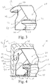
Fig. 3 : is a schematic cross-sectional view of the gasket offig. 2 , -
Fig. 4 : is a schematic cross-sectional view of the gasket offig. 3 in assembled state of the packaging offig. 1 and -
Fig. 5 : is a schematic cross-sectional view of the gasket offig. 3 in assembled state of a packaging according to another prefered embodiment of the invention. - The
packaging 10 as illustrated infig. 1 comprises acontainer 12 and a significantly smalleradditional compartment 14. Thecontainer 12 can be manufactured from polyethylene by blow moulding. Theadditional compartment 14 can in particular be manufactured from polypropylene by plastic injection moulding. Theadditional compartment 14 may comprises a spoon for removing a part of the filling material. Alid 16 is connected to theadditional compartment 14 via a film hinge. Theadditional compartment 14 may be connected to the container as described inWO 2009/147194 A2 so that in turn thelid 16 is also connected to thecontainer 12. The container comprises acollar 18 bordering anopening 20 for providing access to the inside of thecontainer 12. Theopening 20 may by sealed by means of ametal sealing foil 22 glued to the collar. In addition agasket 24 as illustrated infig. 2 is provided, which may be connected to thecollar 18 of the container in a sealing manner and may be pressed against thelid 16 in the closed state of thelid 16 so that theopening 20 may be sufficiently sealed after removing themetal dealing foil 22 for providing access to the filling material the first time. - In the illustrated embodiment the
lid 16 and thecontainer 12 are distributed over different parts. In the alternate the lid may be one-piece with the container, wherein particularly thelid 16 is connected to the container via a film hinge. If so, theadditional compartment 14 may be omitted or be also one-piece with thecontainer 12 in the alternate embodiment. - The
gasket 24 as illustrated infig. 2 andfig. 3 comprises aring body 26 which can be deformed, particularly stretched, and pressed by means of its resilient force onto the collar. The form of thering body 26 may correspond mainly to a radial face of thecollar 18. In the illustrated embodiment anose 28 protrudes from thering body 26 radially inwards for being received into agroove 30 of thecollar 18 so that thegasket 24 encompasses an undercut 32 of the collar as illustrated infig. 4 . Thenose 28 transits into alower front face 34 of thering body 26. Thering body 26 further comprises astop face 36 arranged opposite to thenose 28. The stop face 36 may meet afront face 38 of thecollar 18 for providing a definite relative axial position of thegasket 24 to thecollar 18 and preferably for clamping a protrudingrim 40 of thecollar 18 between thestop face 36 and thenose 28. The protrudingrim 40 provides the undercut 32 of the collar. - A
flap 42 protrudes from thering body 26 particularly radially outwards. Theflap 42 transits into an upper front face 50 of thering body 26. When thelid 16 is closed as illustrated infig. 4 thelid 18 may meet acontact area 52 of theflap 42 and bend theflap 42 towards thering body 26 so that an increasing resilient force is provided by thebent flap 42. In the alternate thecontact area 52 may be nearly linear, so that a frictional relative movement of thelid 16 relative to theflap 42 may be reduced. Thelid 16 may comprise atop part 44 from which aside wall 46 may protrude for providing a mainly U-shaped cross section. Theside wall 46 may aligned orthogonal to thetop part 44 or inclined with respect to the top part running towards or particularly away from thecollar 18 in the closed state. Particularly theside wall 46 only bends theflap 42. Thering body 26 may comprise apocket 48 into which theflap 42 may be bent. Thecontact area 52 of the flap and anouter lateral area 54 of the ring body may or may not arranged mainly flush in the maximum bent state of theflap 42. - As illustrated in
fig. 5 a frame-like closure part 56 may be connected to thecontainer 12. Theclosure part 56 may comprise atube part 58 protruding upwards in axial direction. Aninner surface 60 of thetube part 58 may press against thering body 26 of thegasket 24 so that thering body 26 and/or thenose 28 are pressed against thecollar 18 increasing the sealing effect. If so, theside wall 46 of thelid 16 is put onto thetube part 58. Thetube part 58 may comprise a chamfer or the like for facilitating the plugging of thelid 16 on thetube part 58. Particularly thelid 16 may be releasably clamped to the closure part, preferably with thetube part 58 of theclosure part 56 and theside wall 46 of thelid 16 laying side by side in close state. In a further embodiment, thegasket 24 may comprise a protruding part protruding radially outwards which can be positioned between theclosure part 56 and the front face of thecontainer 12.
Claims (14)
- Packaging for receiving a filling material, comprising
a container (12) for storing the filling material,
wherein the container (12) comprises a collar (18) for bordering an opening (20) for providing access to the filling material, wherein the collar (18) comprises an undercut (32) running in circumferential direction,
a lid (16) for covering the opening (20) in closed state and
a gasket (24) made from an elastic material for sealing the opening (20), wherein the gasket (24) comprisesa ring body (26) for surrounding the opening (20),a nose (28) protruding mainly radially from the ring body (26), wherein the gasket (24) encompasses the undercut (32) by means of the nose (28) for connecting the gasket (24) to the collar (18) in a sealing manner, anda flap (42) protruding mainly radially from the ring body (26), wherein the flap (42) is adapted to seal the lid (16) in closed state of the lid (16). - Packaging according to claim 1 wherein a closure part (56) surrounding the collar (18) is connected to the container (12), wherein the gasket (24) is fastened, particularly clamped, between the collar (18) and the closure part (56).
- Packaging according to claim 1 or 2 wherein the flap (42) protrudes mainly radially outwards from the ring body (26), wherein the flap (42) is bent by the lid (16) in the closed state.
- Packaging according to claim 3 wherein the ring body (26) comprises a pocket (48) for receiving the flap (42) in the maximum bent state, wherein particularly a contact area (52) of the flap (42) for contacting the lid (16) and an outer lateral area (54) of the ring body (26) outside the pocket (48) are arranged mainly flush in the maximum bent state of the flap (42).
- Packaging according to anyone of claims 1 to 4 wherein a contact area (52) of the flap (42) for contacting the lid (16) transits into an upper front face (50) of the ring body (26).
- Packaging according to anyone of claims 1 to 5 wherein the gasket (24) comprises a hardness h in Shore A according to DIN ISO 7619-1:2010 at 23°C of 5 ≤ h ≤ 90.
- Packaging according to anyone of claims 1 to 6 wherein the nose (28) transits into a lower front face (34) of the ring body (26).
- Packaging according to anyone of claims 1 to 7 wherein the nose (28) protrudes mainly radially inwards from the ring body (26), wherein the undercut (32) is provided at the radial outer lateral area of the collar (18).
- Packaging according to anyone of claims 1 to 9 wherein the collar (18) comprises a front face (38) pointing away from the remaining container (12), wherein a sealing foil (24) is connected to the front face (38).
- Packaging according to anyone of claims 1 to 9 wherein the collar (18) comprises a front face (38) pointing away from the remaining container (12), wherein the ring body (26) comprise a stop face (36) for meeting the front face (38).
- Packaging according to claim 10 wherein the undercut (32) is press fitted between the nose (28) and the stop face (36).
- Packaging according to anyone of claims 1 to 11 wherein the undercut (32) is provided by a groove (30) provided in the collar (18).
- Packaging according to anyone of claims 1 to 12 wherein a material sensitive to the environmental atmosphere, particularly a hygroscopic material, is provided inside the container (12), wherein particularly the material comprises or consists of a cosmetic product, particularly a bleaching powder.
- Packaging according to anyone of claims 1 to 13 wherein the ring body (26), the nose (28) and the flap (42) are one-piece for forming the gasket (24).
Priority Applications (5)
| Application Number | Priority Date | Filing Date | Title |
|---|---|---|---|
| EP16207345.6A EP3342726A1 (en) | 2016-12-29 | 2016-12-29 | Packaging for receiving a filling material |
| US16/474,143 US11180297B2 (en) | 2016-12-29 | 2017-12-18 | Packaging for receiving a filling material |
| EP17826206.9A EP3562754A1 (en) | 2016-12-29 | 2017-12-18 | Packaging for receiving a filling material |
| PCT/EP2017/083380 WO2018122024A1 (en) | 2016-12-29 | 2017-12-18 | Packaging for receiving a filling material |
| CN201780080724.3A CN110114281A (en) | 2016-12-29 | 2017-12-18 | For receiving the packing device of packing material |
Applications Claiming Priority (1)
| Application Number | Priority Date | Filing Date | Title |
|---|---|---|---|
| EP16207345.6A EP3342726A1 (en) | 2016-12-29 | 2016-12-29 | Packaging for receiving a filling material |
Publications (1)
| Publication Number | Publication Date |
|---|---|
| EP3342726A1 true EP3342726A1 (en) | 2018-07-04 |
Family
ID=57737620
Family Applications (2)
| Application Number | Title | Priority Date | Filing Date |
|---|---|---|---|
| EP16207345.6A Withdrawn EP3342726A1 (en) | 2016-12-29 | 2016-12-29 | Packaging for receiving a filling material |
| EP17826206.9A Withdrawn EP3562754A1 (en) | 2016-12-29 | 2017-12-18 | Packaging for receiving a filling material |
Family Applications After (1)
| Application Number | Title | Priority Date | Filing Date |
|---|---|---|---|
| EP17826206.9A Withdrawn EP3562754A1 (en) | 2016-12-29 | 2017-12-18 | Packaging for receiving a filling material |
Country Status (4)
| Country | Link |
|---|---|
| US (1) | US11180297B2 (en) |
| EP (2) | EP3342726A1 (en) |
| CN (1) | CN110114281A (en) |
| WO (1) | WO2018122024A1 (en) |
Families Citing this family (2)
| Publication number | Priority date | Publication date | Assignee | Title |
|---|---|---|---|---|
| MX379729B (en) * | 2016-03-04 | 2025-03-11 | Csp Technologies Inc | CONTAINER AND LID. |
| FR3105186B1 (en) * | 2019-12-20 | 2021-11-12 | Abc Transfer | WATERPROOF CONTAINER INCLUDING A DEVICE ALLOWING REMOVABLE CONNECTION TO A SPEAKER |
Citations (5)
| Publication number | Priority date | Publication date | Assignee | Title |
|---|---|---|---|---|
| US1629346A (en) * | 1926-07-20 | 1927-05-17 | Samuel E Larson | Gasket for fruit jars |
| FR2387853A1 (en) * | 1977-04-23 | 1978-11-17 | Honma Zensho | PLASTIC MATERIAL ENCAPSULATION DEVICE FOR CONTAINERS |
| CH651722A5 (en) * | 1981-03-17 | 1985-10-15 | Rudolf Staub | Milking machine with a sealing ring arranged between a collecting container and a cover |
| WO2009147194A2 (en) | 2008-06-05 | 2009-12-10 | Kpss-Kao Professional Salon Services Gmbh | Packaging, use of a packaging and method for assembling several packaging |
| US8511499B2 (en) | 2007-12-18 | 2013-08-20 | Abbott Laboratories | Container |
Family Cites Families (12)
| Publication number | Priority date | Publication date | Assignee | Title |
|---|---|---|---|---|
| US2910209A (en) * | 1953-08-18 | 1959-10-27 | Walter K Nelson | Sealer strips |
| US3302822A (en) * | 1962-10-24 | 1967-02-07 | Illinois Tool Works | Pressure equalizing package |
| US3433383A (en) * | 1968-02-05 | 1969-03-18 | Clifton E Phibbs | Laundry carryall or totebasket |
| JP3847383B2 (en) * | 1996-10-01 | 2006-11-22 | 株式会社資生堂 | Airtight cosmetic container |
| EP1409584B1 (en) * | 2001-02-13 | 2010-01-20 | GLS Corporation | Removable seal of essentially gas-impermeable thermoplastic elastomer |
| US6817473B2 (en) * | 2001-05-10 | 2004-11-16 | Wsl, Llc | Household product package with tamper evident cap |
| JP4498766B2 (en) | 2004-02-10 | 2010-07-07 | 紀伊産業株式会社 | Compact container |
| US9457941B2 (en) * | 2010-02-03 | 2016-10-04 | Tomoya Kawakami | Multipurpose elastic loop gasket |
| AT512907B1 (en) * | 2012-08-02 | 2013-12-15 | Bategu Gummitechnologie Gmbh & Co Kg | Flame-retardant polymeric composition |
| KR101299487B1 (en) | 2013-03-22 | 2013-08-29 | 연희화학공업 주식회사 | Airtight container for cosmetic and method for manufacturing the same |
| KR101584512B1 (en) | 2015-02-16 | 2016-01-25 | (주)아모레퍼시픽 | Cosmetic container with refill case having a seal ring |
| CN204937849U (en) | 2015-07-20 | 2016-01-06 | 福建南鼎纺织科技有限公司 | A kind of seal casing for preventing material from contacting with air |
-
2016
- 2016-12-29 EP EP16207345.6A patent/EP3342726A1/en not_active Withdrawn
-
2017
- 2017-12-18 WO PCT/EP2017/083380 patent/WO2018122024A1/en not_active Ceased
- 2017-12-18 US US16/474,143 patent/US11180297B2/en not_active Expired - Fee Related
- 2017-12-18 CN CN201780080724.3A patent/CN110114281A/en active Pending
- 2017-12-18 EP EP17826206.9A patent/EP3562754A1/en not_active Withdrawn
Patent Citations (5)
| Publication number | Priority date | Publication date | Assignee | Title |
|---|---|---|---|---|
| US1629346A (en) * | 1926-07-20 | 1927-05-17 | Samuel E Larson | Gasket for fruit jars |
| FR2387853A1 (en) * | 1977-04-23 | 1978-11-17 | Honma Zensho | PLASTIC MATERIAL ENCAPSULATION DEVICE FOR CONTAINERS |
| CH651722A5 (en) * | 1981-03-17 | 1985-10-15 | Rudolf Staub | Milking machine with a sealing ring arranged between a collecting container and a cover |
| US8511499B2 (en) | 2007-12-18 | 2013-08-20 | Abbott Laboratories | Container |
| WO2009147194A2 (en) | 2008-06-05 | 2009-12-10 | Kpss-Kao Professional Salon Services Gmbh | Packaging, use of a packaging and method for assembling several packaging |
Also Published As
| Publication number | Publication date |
|---|---|
| EP3562754A1 (en) | 2019-11-06 |
| CN110114281A (en) | 2019-08-09 |
| WO2018122024A1 (en) | 2018-07-05 |
| US11180297B2 (en) | 2021-11-23 |
| US20190344943A1 (en) | 2019-11-14 |
Similar Documents
| Publication | Publication Date | Title |
|---|---|---|
| RU2458832C2 (en) | Corking device with valve and method of its fabrication | |
| US9573750B2 (en) | Aerosol container with removable outlet valve | |
| EP2655206B1 (en) | Device for packaging a product, in particular a cosmetic product, having a sealing member | |
| JP7436162B2 (en) | Synthetic resin container | |
| WO2016005240A1 (en) | Container | |
| WO1999061323A3 (en) | Barrel with plastic lid | |
| CN103946121A (en) | Sealing overcap for a container | |
| CA3166445A1 (en) | Container | |
| CA2528254A1 (en) | Synthetic resin cap, closing device, and beverage-filled container | |
| CN102781786B (en) | Container with lid | |
| CN1777548A (en) | Closures for fluid product containers | |
| CN106170278A (en) | Medical liquid container | |
| US11180297B2 (en) | Packaging for receiving a filling material | |
| CN114174185A (en) | Container cover and container combined with same | |
| CN107021292B (en) | Air Purging Units for Airless Liquid Product Dispensers | |
| US20140158687A1 (en) | Moisture Retention Seal | |
| CN102469893B (en) | Grinder container | |
| US20110309279A1 (en) | Flow valve with integral spring and seal | |
| US20190337684A1 (en) | Packaging for receiving a filling material | |
| JP5193848B2 (en) | Container with lid | |
| JP3224712U (en) | Sealed structure for storage containers and storage containers | |
| JP6903936B2 (en) | Mouth plug | |
| CN107567419A (en) | Container with two seals | |
| JP7372748B2 (en) | container | |
| KR200383487Y1 (en) | A cosmetic refill case |
Legal Events
| Date | Code | Title | Description |
|---|---|---|---|
| PUAI | Public reference made under article 153(3) epc to a published international application that has entered the european phase |
Free format text: ORIGINAL CODE: 0009012 |
|
| STAA | Information on the status of an ep patent application or granted ep patent |
Free format text: STATUS: THE APPLICATION HAS BEEN PUBLISHED |
|
| AK | Designated contracting states |
Kind code of ref document: A1 Designated state(s): AL AT BE BG CH CY CZ DE DK EE ES FI FR GB GR HR HU IE IS IT LI LT LU LV MC MK MT NL NO PL PT RO RS SE SI SK SM TR |
|
| AX | Request for extension of the european patent |
Extension state: BA ME |
|
| STAA | Information on the status of an ep patent application or granted ep patent |
Free format text: STATUS: THE APPLICATION IS DEEMED TO BE WITHDRAWN |
|
| 18D | Application deemed to be withdrawn |
Effective date: 20190105 |