EP3342648B1 - Impact energy absorber member for a vehicle - Google Patents
Impact energy absorber member for a vehicle Download PDFInfo
- Publication number
- EP3342648B1 EP3342648B1 EP16207446.2A EP16207446A EP3342648B1 EP 3342648 B1 EP3342648 B1 EP 3342648B1 EP 16207446 A EP16207446 A EP 16207446A EP 3342648 B1 EP3342648 B1 EP 3342648B1
- Authority
- EP
- European Patent Office
- Prior art keywords
- impact energy
- energy absorber
- vehicle
- front bumper
- radiator
- Prior art date
- Legal status (The legal status is an assumption and is not a legal conclusion. Google has not performed a legal analysis and makes no representation as to the accuracy of the status listed.)
- Active
Links
Images


Classifications
-
- B—PERFORMING OPERATIONS; TRANSPORTING
- B60—VEHICLES IN GENERAL
- B60R—VEHICLES, VEHICLE FITTINGS, OR VEHICLE PARTS, NOT OTHERWISE PROVIDED FOR
- B60R19/00—Wheel guards; Radiator guards, e.g. grilles; Obstruction removers; Fittings damping bouncing force in collisions
- B60R19/02—Bumpers, i.e. impact receiving or absorbing members for protecting vehicles or fending off blows from other vehicles or objects
- B60R19/24—Arrangements for mounting bumpers on vehicles
-
- B—PERFORMING OPERATIONS; TRANSPORTING
- B60—VEHICLES IN GENERAL
- B60R—VEHICLES, VEHICLE FITTINGS, OR VEHICLE PARTS, NOT OTHERWISE PROVIDED FOR
- B60R19/00—Wheel guards; Radiator guards, e.g. grilles; Obstruction removers; Fittings damping bouncing force in collisions
- B60R19/52—Radiator or grille guards ; Radiator grilles
-
- B—PERFORMING OPERATIONS; TRANSPORTING
- B60—VEHICLES IN GENERAL
- B60R—VEHICLES, VEHICLE FITTINGS, OR VEHICLE PARTS, NOT OTHERWISE PROVIDED FOR
- B60R19/00—Wheel guards; Radiator guards, e.g. grilles; Obstruction removers; Fittings damping bouncing force in collisions
-
- B—PERFORMING OPERATIONS; TRANSPORTING
- B60—VEHICLES IN GENERAL
- B60R—VEHICLES, VEHICLE FITTINGS, OR VEHICLE PARTS, NOT OTHERWISE PROVIDED FOR
- B60R19/00—Wheel guards; Radiator guards, e.g. grilles; Obstruction removers; Fittings damping bouncing force in collisions
- B60R19/02—Bumpers, i.e. impact receiving or absorbing members for protecting vehicles or fending off blows from other vehicles or objects
- B60R19/023—Details
-
- B—PERFORMING OPERATIONS; TRANSPORTING
- B60—VEHICLES IN GENERAL
- B60R—VEHICLES, VEHICLE FITTINGS, OR VEHICLE PARTS, NOT OTHERWISE PROVIDED FOR
- B60R21/00—Arrangements or fittings on vehicles for protecting or preventing injuries to occupants or pedestrians in case of accidents or other traffic risks
- B60R21/34—Protecting non-occupants of a vehicle, e.g. pedestrians
-
- B—PERFORMING OPERATIONS; TRANSPORTING
- B62—LAND VEHICLES FOR TRAVELLING OTHERWISE THAN ON RAILS
- B62D—MOTOR VEHICLES; TRAILERS
- B62D25/00—Superstructure or monocoque structure sub-units; Parts or details thereof not otherwise provided for
- B62D25/08—Front or rear portions
-
- B—PERFORMING OPERATIONS; TRANSPORTING
- B60—VEHICLES IN GENERAL
- B60R—VEHICLES, VEHICLE FITTINGS, OR VEHICLE PARTS, NOT OTHERWISE PROVIDED FOR
- B60R21/00—Arrangements or fittings on vehicles for protecting or preventing injuries to occupants or pedestrians in case of accidents or other traffic risks
- B60R21/34—Protecting non-occupants of a vehicle, e.g. pedestrians
- B60R2021/343—Protecting non-occupants of a vehicle, e.g. pedestrians using deformable body panel, bodywork or components
Definitions
- the invention relates to a front module for a vehicle and a vehicle with such a front module.
- Vehicles need to have air guiding parts behind the grilles of the front bumper of the vehicle for better engine cooling and aerodynamic performance.
- vehicles need pedestrian protection lower leg impact energy absorber in front of bumper beam which is also behind the front fascia & grilles. Cost and assembly issues emerged because of current design while maintaining pedestrian protection and low speed damageability safety targets.
- FR 2 965 226 A1 discloses a device with an upper reinforcement, a lower reinforcement and two jambs connecting the upper reinforcement and the lower reinforcement so as to define a frame.
- the upper reinforcement and the lower reinforcement are provided with shock absorbers, where one of the shock absorbers is laid at ends of the upper reinforcement. Another shock absorber extends through the lower reinforcement. Deflectors are arranged partly around the frame.
- DE 10 2008 004 311 A1 discloses a device with an air guiding element mechanically adjusted between a rest position and an operating position around a horizontal vehicle transverse axis.
- the element is adjusted by a dynamic pressure flap depending on the dynamic pressure acting at the flap.
- the flap is rotatable supported around a horizontal rotation axis.
- the flap is partially integrated in a lower body region of a bumper unit and/or a body-sided cover, and in between the bumper unit and an engine compartment cover, where the cover is arranged below the bumper unit.
- JPS 6231546 A discloses an air-spoiler which is fixed to the lower wall of a bumper fascia, and which is incorporated at its upper rear end integrally with an air guide projected rearward and made to be flush with the lower surface entering into the outside air introduction port is rectified by the air guide so that air flows toward a radiator being stably guided.
- FR 2 927 033 A1 discloses an energy absorbing beam for front bumper of motor vehicle, has cross-piece including holes extending longitudinally along direction of absorbers and forming air inlet grill of front bumper, where absorbers are arranged at ends of cross-piece.
- the beam has absorbers arranged at ends of a cross-piece and extending substantially perpendicular to the cross-piece.
- the cross-piece includes through holes extending longitudinally along a direction of the absorbers, and forms an air inlet grill of a front bumper. Bumper skin of the bumper is arranged between a shock absorption band and the beam, where the holes of the cross-piece, holes of the band and holes of another air inlet grill form a global air inlet grill presenting a surface.
- EP 1 352 810 A2 discloses a structure of a front portion of a vehicle body with an air duct. A portion between a front end of an air guide plates, which forms an air duct portion, and the front exterior member of the vehicle is sealed by a seal portion. Therefore, hot air leaking from inside of an engine room, is positively prevented from being drawn into the air duct portion after it flows around the front end of the air guide plate.
- a front module for a vehicle comprises at least an impact energy absorber member, a front bumper, and a bolster frame, characterised by a lower leg robener, wherein the lower leg stiffener is configured to stiffen the pedestrian protection in order to protect a lower leg of a pedestrian, comprises integrated air guiding means for guiding air from the front bumper member of the vehicle to a radiator of the vehicle, wherein the integrated air guiding means comprises at least one vertical flap, wherein the flap is reinforced by a rib, wherein the rib is fixed to the front bumper and the radiator in the direction of streaming air flow.
- a cooling air flow passed first the front bumper, then the impact energy absorber, and then the radiator.
- the at least one vertical flap ensure air flow and therefore effective cooling. Since the rib is fixed to the front bumper member and/or to the bolster frame the rib is part of the front bumper and/or of bolster frame. They are brought into contact during assembly of the front module.
- the rib can be an integrally part of the front bumper member and/or the bolster frame, for example, if the front bumper member and/or bolster frame is plastic or metal injection moulded.
- the impact energy absorber member comprises a snap fit for fixing to the front bumper member. This allows an easy assembly of the front module without using additional fixing means like screws, bolts, or the like.
- the bolster frame is arranged between the impact energy absorber member and the radiator. Accordingly, the impact energy absorber member is arranged between the front bumper and the radiator in the direction of streaming air flow. In other words, a cooling air flow passed first the front bumper, then the impact energy absorber, and then the radiator.
- the at least one vertical flap ensure air flow and therefore effective cooling. Since the rib is fixed to the front bumper member and/or to the bolster frame the rib is part of the front bumper and/or of bolster frame. They are brought into contact during assembly of the front module.
- the rib can be an integrally part of the front bumper member and/or the bolster frame, for example, if the front bumper member and/or bolster frame is plastic or metal injection moulded.
- the impact energy absorber member comprises a snap fit for fixing to the front bumper member. This allows an easy assembly of the front module without using additional fixing means like screws, bolts, or the like.
- the bolster frame is arranged between the impact energy absorber member and the radiator. Accordingly, the bolster is arranged between the front bumper and the radiator in the direction of streaming air flow. In other words, a cooling air flow passed first the front bumper, then the bumper, and then the radiator.
- the invention relates to a vehicle with such a front module.
- the front module 10 for a vehicle comprises an impact energy absorber member 1, a front bumper 2, a lower leg stiffener 3, a front bumper beam 4, a bolster frame 5, and a radiator 6.
- the first place will be the front bumper 2, followed by the lower leg stiffener 3, the impact energy absorber 1, the front bumper beam 4, the bolster frame 5, and the radiator 6.
- the impact energy absorber member 1 is configured to route air coming from the front bumper 2 to the radiator 6 which is part of an engine cooling system of the vehicle.
- the impact energy absorber member 1 comprises air guiding means 7 configured to ensure air flow and therefore effective cooling.
- the air guide means 7 are four flaps 8 which are vertically orientated.
- the four flaps 8, and therefore the air guiding means are integrated parts of the impact energy absorber member 1.
- the impact energy absorber member 1 comprises a snap fit for fixing to the front bumper 2.
- the front bumper 2 comprises a rib 9a which, when assembled, stays in contact with the flap 8 to reinforce the flap 8.
- the bolster frame 5 comprises a rib 9b which, when assembled, stays in contact with the flap 8 to reinforce the flap 8.
- the lower leg stiffener 3 is configured to stiffen the pedestrian protection.
- the front bumper beam 4 comprises crash-cans.
- the bolster frame 5 is configured to reinforce the front bumper 2 and the radiator 6.
- the front module 10 and its parts e.g. the impact energy absorber member 1 with the air guiding means 7, e.g. the flaps 8, the front bumper 2 with the rib 9a, the lover leg stiffener 3, the front bumper beam 4, the bolster frame 5 with the rib 9b can fabricated by plastic or metal injection moulded and therefore configured as integrally parts, respectively.
Landscapes
- Engineering & Computer Science (AREA)
- Mechanical Engineering (AREA)
- Chemical & Material Sciences (AREA)
- Combustion & Propulsion (AREA)
- Transportation (AREA)
- Body Structure For Vehicles (AREA)
- Cooling, Air Intake And Gas Exhaust, And Fuel Tank Arrangements In Propulsion Units (AREA)
Description
- The invention relates to a front module for a vehicle and a vehicle with such a front module.
- Vehicles need to have air guiding parts behind the grilles of the front bumper of the vehicle for better engine cooling and aerodynamic performance. Although vehicles need pedestrian protection lower leg impact energy absorber in front of bumper beam which is also behind the front fascia & grilles. Cost and assembly issues emerged because of current design while maintaining pedestrian protection and low speed damageability safety targets.
-
FR 2 965 226 A1 -
DE 10 2008 004 311 A1 discloses a device with an air guiding element mechanically adjusted between a rest position and an operating position around a horizontal vehicle transverse axis. The element is adjusted by a dynamic pressure flap depending on the dynamic pressure acting at the flap. The flap is rotatable supported around a horizontal rotation axis. The flap is partially integrated in a lower body region of a bumper unit and/or a body-sided cover, and in between the bumper unit and an engine compartment cover, where the cover is arranged below the bumper unit. - JPS 6231546 A discloses an air-spoiler which is fixed to the lower wall of a bumper fascia, and which is incorporated at its upper rear end integrally with an air guide projected rearward and made to be flush with the lower surface entering into the outside air introduction port is rectified by the air guide so that air flows toward a radiator being stably guided.
-
FR 2 927 033 A1 -
EP 1 352 810 A2 - It is therefore an object of the invention to reduce assembly process timing, costs, and weight and to improve the protection of lower a lower leg of a pedestrian.
- A front module for a vehicle according to the invention comprises at least an impact energy absorber member, a front bumper, and a bolster frame, characterised by a lower leg stiftener, wherein the lower leg stiffener is configured to stiffen the pedestrian protection in order to protect a lower leg of a pedestrian, comprises integrated air guiding means for guiding air from the front bumper member of the vehicle to a radiator of the vehicle, wherein the integrated air guiding means comprises at least one vertical flap, wherein the flap is reinforced by a rib, wherein the rib is fixed to the front bumper and the radiator in the direction of streaming air flow. In other words, a cooling air flow passed first the front bumper, then the impact energy absorber, and then the radiator. Thus, by the integrated guiding means air flow will be provided in one piece part instead of three different parts. Therefore, assembly and cost advantages will be gained. The at least one vertical flap ensure air flow and therefore effective cooling. Since the rib is fixed to the front bumper member and/or to the bolster frame the rib is part of the front bumper and/or of bolster frame. They are brought into contact during assembly of the front module. The rib can be an integrally part of the front bumper member and/or the bolster frame, for example, if the front bumper member and/or bolster frame is plastic or metal injection moulded.
- In a preferred embodiment the impact energy absorber member comprises a snap fit for fixing to the front bumper member. This allows an easy assembly of the front module without using additional fixing means like screws, bolts, or the like.
- In a preferred embodiment the bolster frame is arranged between the impact energy absorber member and the radiator. Accordingly, the impact energy absorber member is arranged between the front bumper and the radiator in the direction of streaming air flow. In other words, a cooling air flow passed first the front bumper, then the impact energy absorber, and then the radiator. Thus, by the integrated guiding means air flow will be provided in one piece part instead of three different parts. Therefore, assembly and cost advantages will be gained. The at least one vertical flap ensure air flow and therefore effective cooling. Since the rib is fixed to the front bumper member and/or to the bolster frame the rib is part of the front bumper and/or of bolster frame. They are brought into contact during assembly of the front module. The rib can be an integrally part of the front bumper member and/or the bolster frame, for example, if the front bumper member and/or bolster frame is plastic or metal injection moulded.
- In a preferred embodiment the impact energy absorber member comprises a snap fit for fixing to the front bumper member. This allows an easy assembly of the front module without using additional fixing means like screws, bolts, or the like.
- In a preferred embodiment the bolster frame is arranged between the impact energy absorber member and the radiator. Accordingly, the bolster is arranged between the front bumper and the radiator in the direction of streaming air flow. In other words, a cooling air flow passed first the front bumper, then the bumper, and then the radiator.
- Further, the invention relates to a vehicle with such a front module.
- An example of the invention will now be described with reference to the following drawing:
- Fig. 1
- shows a front module of a vehicle.
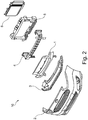
- Fig. 2
- shows an explosion view of a front module shown in
Fig. 1 . - Fig. 3
- shows assembled part of front module shown in
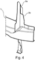
Fig. 2 . - Fig. 4
- shows details of the front module shown in
Fig. 1 . - Reference is made to
Fig. 1 and2 . Thefront module 10 for a vehicle comprises an impactenergy absorber member 1, afront bumper 2, alower leg stiffener 3, afront bumper beam 4, a bolster frame 5, and aradiator 6. - As shown in
Fig. 2 , in the direction of air flow the first place will be thefront bumper 2, followed by thelower leg stiffener 3, the impact energy absorber 1, thefront bumper beam 4, the bolster frame 5, and theradiator 6. - The impact
energy absorber member 1 is configured to route air coming from thefront bumper 2 to theradiator 6 which is part of an engine cooling system of the vehicle. - Therefore, as shown in
Fig.3 , the impactenergy absorber member 1 comprises air guiding means 7 configured to ensure air flow and therefore effective cooling. In present example the air guide means 7 are four flaps 8 which are vertically orientated. The four flaps 8, and therefore the air guiding means, are integrated parts of the impactenergy absorber member 1. Moreover, the impactenergy absorber member 1 comprises a snap fit for fixing to thefront bumper 2. - As shown in
Fig. 4 , thefront bumper 2 comprises arib 9a which, when assembled, stays in contact with the flap 8 to reinforce the flap 8. Also, in the same manner, the bolster frame 5 comprises arib 9b which, when assembled, stays in contact with the flap 8 to reinforce the flap 8. - The
lower leg stiffener 3 is configured to stiffen the pedestrian protection. Thefront bumper beam 4 comprises crash-cans. The bolster frame 5 is configured to reinforce thefront bumper 2 and theradiator 6. - The
front module 10 and its parts, e.g. the impactenergy absorber member 1 with the air guiding means 7, e.g. the flaps 8, thefront bumper 2 with therib 9a, thelover leg stiffener 3, thefront bumper beam 4, the bolster frame 5 with therib 9b can fabricated by plastic or metal injection moulded and therefore configured as integrally parts, respectively. - Thus, this will lead to reduced assembly process timing, costs, and weight.
-
- 1
- impact energy absorber member
- 2
- front bumper
- 3
- lower leg stiffener
- 4
- front bumper beam
- 5
- bolster frame
- 6
- radiator
- 7
- air guiding means
- 8
- flap
- 9a
- rib
- 9b
- rib
- 10
- front module
Claims (4)
- Front module (10) for a vehicle with at least an impact energy absorber member (1), a front bumper (2), a lower leg stiffener (3), and a bolster frame (5), wherein the lower leg stiffener (3) is configured to stiffen the pedestrian protection in order to protect a lower leg of a pedestrian, with integrated air guiding means (7) for guiding air from the front bumper member (2) of the vehicle to a radiator (6) of the vehicle, wherein the impact energy absorber member (1) comprises integrated air guiding means (7) with at least one vertical flap (8), wherein the flap (8) is reinforced by a rib (9a, 9b), wherein the rib (9a) is fixed to the front bumper member (2) and to the bolster frame (5) of the front module (10), wherein the flap (8), and therefore the air guiding means (7), are integrated parts of the impact energy absorber (1).
- Front module (10) according to claim 1, wherein the impact energy absorber member (1) comprises a snap fit for fixing to the front bumper member (2).
- Front module (10) according to claim 1 or 2, wherein the bolster frame (5) is arranged between the impact energy absorber member (1) and the radiator (6).
- Vehicle with a front module (10) according to one of the claims 1 to 3.
Priority Applications (3)
| Application Number | Priority Date | Filing Date | Title |
|---|---|---|---|
| EP16207446.2A EP3342648B1 (en) | 2016-12-30 | 2016-12-30 | Impact energy absorber member for a vehicle |
| US15/827,351 US10464514B2 (en) | 2016-12-30 | 2017-11-30 | Impact energy absorber member for a vehicle |
| CN201711430787.5A CN108275098B (en) | 2016-12-30 | 2017-12-26 | Impact energy absorbing member for vehicle |
Applications Claiming Priority (1)
| Application Number | Priority Date | Filing Date | Title |
|---|---|---|---|
| EP16207446.2A EP3342648B1 (en) | 2016-12-30 | 2016-12-30 | Impact energy absorber member for a vehicle |
Publications (2)
| Publication Number | Publication Date |
|---|---|
| EP3342648A1 EP3342648A1 (en) | 2018-07-04 |
| EP3342648B1 true EP3342648B1 (en) | 2020-02-19 |
Family
ID=57629486
Family Applications (1)
| Application Number | Title | Priority Date | Filing Date |
|---|---|---|---|
| EP16207446.2A Active EP3342648B1 (en) | 2016-12-30 | 2016-12-30 | Impact energy absorber member for a vehicle |
Country Status (3)
| Country | Link |
|---|---|
| US (1) | US10464514B2 (en) |
| EP (1) | EP3342648B1 (en) |
| CN (1) | CN108275098B (en) |
Families Citing this family (33)
| Publication number | Priority date | Publication date | Assignee | Title |
|---|---|---|---|---|
| USD882465S1 (en) * | 2018-02-13 | 2020-04-28 | Ningbo Geely Automobile Research & Development Co. | Grille for vehicle |
| USD870611S1 (en) * | 2018-03-02 | 2019-12-24 | Ford Global Technologies, Llc | Vehicle rear upper bumper cover |
| USD871982S1 (en) * | 2018-03-02 | 2020-01-07 | Ford Global Technologies, Llc | Vehicle front upper bumper cover |
| USD881079S1 (en) * | 2018-08-09 | 2020-04-14 | Ford Global Technologies, Llc | Vehicle front lower grille |
| USD881085S1 (en) * | 2018-08-09 | 2020-04-14 | Ford Global Technologies, Llc | Vehicle rear bumper cover |
| USD893366S1 (en) * | 2018-08-09 | 2020-08-18 | Ford Global Technologies, Llc | Vehicle front lower bumper cover |
| USD881086S1 (en) * | 2018-08-09 | 2020-04-14 | Ford Global Technologies, Llc | Vehicle rear bumper cover |
| USD927367S1 (en) * | 2019-11-08 | 2021-08-10 | Hyundai Motor Company | Radiator grille for vehicles |
| USD926644S1 (en) * | 2019-11-08 | 2021-08-03 | Hyundai Motor Company | Radiator grille for vehicles equipped with a lamp for vehicles |
| CN111086564B (en) * | 2020-01-08 | 2021-05-04 | 上海龙创汽车设计股份有限公司 | Connecting structure of wind scooper and anti-collision beam |
| CN111216671B (en) * | 2020-01-17 | 2021-08-31 | 东风汽车集团有限公司 | Pedestrian protection structure for automobile and automobile |
| US11292334B2 (en) * | 2020-03-04 | 2022-04-05 | Ford Global Technologies, Llc | Stacked reinforcement assembly for grille of motor vehicle |
| USD906191S1 (en) * | 2020-07-13 | 2020-12-29 | Seven Sparta Corp. | Vehicle front grille |
| US11338749B2 (en) * | 2020-09-03 | 2022-05-24 | GM Global Technology Operations LLC | Bumper assembly for an automotive vehicle |
| USD1033284S1 (en) * | 2022-04-01 | 2024-07-02 | Hyundai Motor Company | Bumper grille for an automobile |
| USD1033282S1 (en) * | 2022-04-01 | 2024-07-02 | Hyundai Motor Company | Bumper grille for an automobile |
| USD1033283S1 (en) * | 2022-04-01 | 2024-07-02 | Hyundai Motor Company | Bumper grille for an automobile |
| USD1018383S1 (en) * | 2022-04-27 | 2024-03-19 | Honda Motor Co., Ltd. | Front grille for automobile |
| USD1044616S1 (en) * | 2022-07-01 | 2024-10-01 | Danyang Weisheng Automobile Technology Co., Ltd. | Car grille |
| USD1069657S1 (en) * | 2022-07-28 | 2025-04-08 | Nissan Motor Co., Ltd. | Front grille for automobile |
| USD1070672S1 (en) | 2022-10-31 | 2025-04-15 | Vaughn Gittin, Jr. Motorsports LLC | Automotive grille inserts |
| USD1061352S1 (en) * | 2022-10-31 | 2025-02-11 | Vaughn Gittin, Jr. Motorsports LLC | Grille assembly for an automobile |
| USD1089732S1 (en) | 2022-10-31 | 2025-08-19 | Vaughn Gittin, Jr. Motorsports LLC—MD | Pair of grille lights for a vehicle |
| USD1070671S1 (en) | 2022-10-31 | 2025-04-15 | Vaughn Gittin, Jr. Motorsports LLC | Automobile grille |
| USD1102984S1 (en) * | 2023-09-11 | 2025-11-25 | Jaguar Land Rover Limited | Vehicle grille |
| TWD232940S (en) * | 2023-10-06 | 2024-08-11 | 巨鎧精密工業股份有限公司 臺南市安南區科技二路50號 (中華民國) | Main body of the grille trim |
| USD1102977S1 (en) * | 2024-02-23 | 2025-11-25 | GM Global Technology Operations LLC | Vehicle grille |
| USD1102978S1 (en) * | 2024-02-27 | 2025-11-25 | GM Global Technology Operations LLC | Vehicle grille |
| USD1102981S1 (en) * | 2024-03-04 | 2025-11-25 | GM Global Technology Operations LLC | Vehicle grille |
| USD1102985S1 (en) * | 2024-03-11 | 2025-11-25 | GM Global Technology Operations LLC | Vehicle lower grille |
| USD1111952S1 (en) * | 2024-09-04 | 2026-02-10 | Audi Ag | Radiator grille for vehicle |
| USD1111951S1 (en) * | 2024-09-04 | 2026-02-10 | Audi Ag | Radiator grille for vehicle |
| USD1123740S1 (en) * | 2024-10-23 | 2026-04-28 | GM Global Technology Operations LLC | Vehicle grille |
Family Cites Families (15)
| Publication number | Priority date | Publication date | Assignee | Title |
|---|---|---|---|---|
| JPS6231546A (en) | 1985-08-02 | 1987-02-10 | Nissan Motor Co Ltd | Outside air introduction device in automobile |
| DE10142796B4 (en) * | 2001-08-31 | 2005-08-25 | Daimlerchrysler Ag | Front area of a motor vehicle and baffle unit for this |
| JP4074122B2 (en) * | 2002-04-11 | 2008-04-09 | カルソニックカンセイ株式会社 | Auto body front structure |
| DE102004035435A1 (en) * | 2004-07-21 | 2006-03-16 | GM Global Technology Operations, Inc., Detroit | Reinforcing element for a lower portion of a front bumper, and thus equipped front bumper for a motor vehicle |
| DE102007033116A1 (en) * | 2007-07-13 | 2009-01-15 | Behr Gmbh & Co. Kg | Front end module for vehicles |
| DE102008004311A1 (en) | 2008-01-15 | 2009-07-16 | Daimler Ag | Air guiding device i.e. spoiler, for e.g. car, has air guiding element mechanically adjusted between rest and operating positions around horizontal vehicle transverse axis by dynamic pressure flap depending on pressure acting at flap |
| FR2927033B1 (en) * | 2008-02-05 | 2010-03-26 | Peugeot Citroen Automobiles Sa | ENERGY ABSORPTION BEAM FOR FRONT BUMPER AND BUMPER BEFORE MOTOR VEHICLE |
| DE102009031746A1 (en) * | 2009-07-06 | 2011-01-13 | GM Global Technology Operations, Inc., Detroit | Cooling air guiding device for a motor vehicle |
| DE102009032592A1 (en) * | 2009-07-10 | 2011-01-13 | GM Global Technology Operations, Inc., Detroit | Front part for motor vehicle body, has bumper and mobile closure element that is arranged in fresh air duct for modulating flow rate of fresh air duct, and bumper carrier provided to form wall for fresh air duct |
| WO2012012535A2 (en) | 2010-07-21 | 2012-01-26 | Shape Corp. | Integrated energy absorber and air flow management structure |
| FR2965226B1 (en) | 2010-09-24 | 2019-04-19 | Valeo Systemes Thermiques | DEVICE FOR GUIDING AN AIR FLOW FOR A MOTOR VEHICLE AND FRONT PANEL COMPRISING SUCH A DEVICE |
| KR101361268B1 (en) * | 2012-12-07 | 2014-02-11 | 현대자동차주식회사 | Front end module for vehicle |
| DE102012222561A1 (en) * | 2012-12-07 | 2014-06-12 | Bayerische Motoren Werke Aktiengesellschaft | front end body |
| JP6135336B2 (en) * | 2013-07-02 | 2017-05-31 | スズキ株式会社 | Fender holder peripheral structure |
| DE102013223105A1 (en) | 2013-11-13 | 2015-05-13 | Röchling Automotive SE & Co. KG | In vehicle carrier integrated gas, especially air guiding device |
-
2016
- 2016-12-30 EP EP16207446.2A patent/EP3342648B1/en active Active
-
2017
- 2017-11-30 US US15/827,351 patent/US10464514B2/en active Active
- 2017-12-26 CN CN201711430787.5A patent/CN108275098B/en active Active
Non-Patent Citations (1)
| Title |
|---|
| None * |
Also Published As
| Publication number | Publication date |
|---|---|
| US10464514B2 (en) | 2019-11-05 |
| CN108275098A (en) | 2018-07-13 |
| EP3342648A1 (en) | 2018-07-04 |
| US20180186319A1 (en) | 2018-07-05 |
| CN108275098B (en) | 2023-11-24 |
Similar Documents
| Publication | Publication Date | Title |
|---|---|---|
| EP3342648A1 (en) | Impact energy absorber member for a vehicle | |
| US10040344B2 (en) | Closing device for closing an essential component of a vehicle | |
| US7967350B2 (en) | Shock absorption module for an automobile | |
| US10870403B2 (en) | Bumper cross member system for a motor vehicle, modular system, and motor vehicle having such a bumper cross member system | |
| US10787141B2 (en) | AGS with displaceable actuator | |
| JP2009083687A (en) | Automotive front structure | |
| EP3659871B1 (en) | Vehicle front structure | |
| US9623824B2 (en) | Gas-guiding device, in particular air-guiding device, integrated in a motor vehicle beam | |
| US20180361847A1 (en) | Suspended grille active shutter | |
| US20080277951A1 (en) | Motor Vehicle Front Part | |
| US10131303B2 (en) | Bumper assemblies and vehicles with integrated air deflectors | |
| US10688862B2 (en) | Air guide for a vehicle front structure | |
| US8777301B2 (en) | Instrument panel arrangement | |
| JP2012144125A (en) | Baffle guide structure for vehicle | |
| CN104724179A (en) | Cowl cross member mounting assembly for vehicle | |
| JP6056738B2 (en) | Vehicle front structure | |
| US10131305B2 (en) | Bumper assemblies and vehicles with integrated air deflectors | |
| CN111212762B (en) | Stowable underbody aerodynamic blades absorbing forces through lower supports | |
| US9248795B1 (en) | Frontal impact energy absorption members | |
| CN214165136U (en) | Wind window crossbeam structure and car | |
| CN109070941A (en) | The front fender structure of motor vehicles | |
| JP5541081B2 (en) | Vehicle cowl structure | |
| CN214366463U (en) | Novel automobile air inlet system | |
| KR20150043855A (en) | Cooling duct structure | |
| KR101637602B1 (en) | Cowl structure |
Legal Events
| Date | Code | Title | Description |
|---|---|---|---|
| PUAI | Public reference made under article 153(3) epc to a published international application that has entered the european phase |
Free format text: ORIGINAL CODE: 0009012 |
|
| STAA | Information on the status of an ep patent application or granted ep patent |
Free format text: STATUS: THE APPLICATION HAS BEEN PUBLISHED |
|
| AK | Designated contracting states |
Kind code of ref document: A1 Designated state(s): AL AT BE BG CH CY CZ DE DK EE ES FI FR GB GR HR HU IE IS IT LI LT LU LV MC MK MT NL NO PL PT RO RS SE SI SK SM TR |
|
| AX | Request for extension of the european patent |
Extension state: BA ME |
|
| STAA | Information on the status of an ep patent application or granted ep patent |
Free format text: STATUS: REQUEST FOR EXAMINATION WAS MADE |
|
| 17P | Request for examination filed |
Effective date: 20190104 |
|
| RBV | Designated contracting states (corrected) |
Designated state(s): AL AT BE BG CH CY CZ DE DK EE ES FI FR GB GR HR HU IE IS IT LI LT LU LV MC MK MT NL NO PL PT RO RS SE SI SK SM TR |
|
| STAA | Information on the status of an ep patent application or granted ep patent |
Free format text: STATUS: EXAMINATION IS IN PROGRESS |
|
| 17Q | First examination report despatched |
Effective date: 20190412 |
|
| GRAP | Despatch of communication of intention to grant a patent |
Free format text: ORIGINAL CODE: EPIDOSNIGR1 |
|
| STAA | Information on the status of an ep patent application or granted ep patent |
Free format text: STATUS: GRANT OF PATENT IS INTENDED |
|
| INTG | Intention to grant announced |
Effective date: 20191204 |
|
| GRAS | Grant fee paid |
Free format text: ORIGINAL CODE: EPIDOSNIGR3 |
|
| GRAA | (expected) grant |
Free format text: ORIGINAL CODE: 0009210 |
|
| STAA | Information on the status of an ep patent application or granted ep patent |
Free format text: STATUS: THE PATENT HAS BEEN GRANTED |
|
| AK | Designated contracting states |
Kind code of ref document: B1 Designated state(s): AL AT BE BG CH CY CZ DE DK EE ES FI FR GB GR HR HU IE IS IT LI LT LU LV MC MK MT NL NO PL PT RO RS SE SI SK SM TR |
|
| REG | Reference to a national code |
Ref country code: CH Ref legal event code: EP |
|
| REG | Reference to a national code |
Ref country code: DE Ref legal event code: R096 Ref document number: 602016029993 Country of ref document: DE |
|
| REG | Reference to a national code |
Ref country code: AT Ref legal event code: REF Ref document number: 1234602 Country of ref document: AT Kind code of ref document: T Effective date: 20200315 |
|
| REG | Reference to a national code |
Ref country code: IE Ref legal event code: FG4D |
|
| REG | Reference to a national code |
Ref country code: NL Ref legal event code: MP Effective date: 20200219 |
|
| PG25 | Lapsed in a contracting state [announced via postgrant information from national office to epo] |
Ref country code: FI Free format text: LAPSE BECAUSE OF FAILURE TO SUBMIT A TRANSLATION OF THE DESCRIPTION OR TO PAY THE FEE WITHIN THE PRESCRIBED TIME-LIMIT Effective date: 20200219 Ref country code: NO Free format text: LAPSE BECAUSE OF FAILURE TO SUBMIT A TRANSLATION OF THE DESCRIPTION OR TO PAY THE FEE WITHIN THE PRESCRIBED TIME-LIMIT Effective date: 20200519 Ref country code: RS Free format text: LAPSE BECAUSE OF FAILURE TO SUBMIT A TRANSLATION OF THE DESCRIPTION OR TO PAY THE FEE WITHIN THE PRESCRIBED TIME-LIMIT Effective date: 20200219 |
|
| REG | Reference to a national code |
Ref country code: LT Ref legal event code: MG4D |
|
| PG25 | Lapsed in a contracting state [announced via postgrant information from national office to epo] |
Ref country code: GR Free format text: LAPSE BECAUSE OF FAILURE TO SUBMIT A TRANSLATION OF THE DESCRIPTION OR TO PAY THE FEE WITHIN THE PRESCRIBED TIME-LIMIT Effective date: 20200520 Ref country code: BG Free format text: LAPSE BECAUSE OF FAILURE TO SUBMIT A TRANSLATION OF THE DESCRIPTION OR TO PAY THE FEE WITHIN THE PRESCRIBED TIME-LIMIT Effective date: 20200519 Ref country code: IS Free format text: LAPSE BECAUSE OF FAILURE TO SUBMIT A TRANSLATION OF THE DESCRIPTION OR TO PAY THE FEE WITHIN THE PRESCRIBED TIME-LIMIT Effective date: 20200619 Ref country code: HR Free format text: LAPSE BECAUSE OF FAILURE TO SUBMIT A TRANSLATION OF THE DESCRIPTION OR TO PAY THE FEE WITHIN THE PRESCRIBED TIME-LIMIT Effective date: 20200219 Ref country code: LV Free format text: LAPSE BECAUSE OF FAILURE TO SUBMIT A TRANSLATION OF THE DESCRIPTION OR TO PAY THE FEE WITHIN THE PRESCRIBED TIME-LIMIT Effective date: 20200219 Ref country code: SE Free format text: LAPSE BECAUSE OF FAILURE TO SUBMIT A TRANSLATION OF THE DESCRIPTION OR TO PAY THE FEE WITHIN THE PRESCRIBED TIME-LIMIT Effective date: 20200219 |
|
| PG25 | Lapsed in a contracting state [announced via postgrant information from national office to epo] |
Ref country code: NL Free format text: LAPSE BECAUSE OF FAILURE TO SUBMIT A TRANSLATION OF THE DESCRIPTION OR TO PAY THE FEE WITHIN THE PRESCRIBED TIME-LIMIT Effective date: 20200219 |
|
| PG25 | Lapsed in a contracting state [announced via postgrant information from national office to epo] |
Ref country code: PT Free format text: LAPSE BECAUSE OF FAILURE TO SUBMIT A TRANSLATION OF THE DESCRIPTION OR TO PAY THE FEE WITHIN THE PRESCRIBED TIME-LIMIT Effective date: 20200712 Ref country code: SM Free format text: LAPSE BECAUSE OF FAILURE TO SUBMIT A TRANSLATION OF THE DESCRIPTION OR TO PAY THE FEE WITHIN THE PRESCRIBED TIME-LIMIT Effective date: 20200219 Ref country code: EE Free format text: LAPSE BECAUSE OF FAILURE TO SUBMIT A TRANSLATION OF THE DESCRIPTION OR TO PAY THE FEE WITHIN THE PRESCRIBED TIME-LIMIT Effective date: 20200219 Ref country code: DK Free format text: LAPSE BECAUSE OF FAILURE TO SUBMIT A TRANSLATION OF THE DESCRIPTION OR TO PAY THE FEE WITHIN THE PRESCRIBED TIME-LIMIT Effective date: 20200219 Ref country code: LT Free format text: LAPSE BECAUSE OF FAILURE TO SUBMIT A TRANSLATION OF THE DESCRIPTION OR TO PAY THE FEE WITHIN THE PRESCRIBED TIME-LIMIT Effective date: 20200219 Ref country code: CZ Free format text: LAPSE BECAUSE OF FAILURE TO SUBMIT A TRANSLATION OF THE DESCRIPTION OR TO PAY THE FEE WITHIN THE PRESCRIBED TIME-LIMIT Effective date: 20200219 Ref country code: ES Free format text: LAPSE BECAUSE OF FAILURE TO SUBMIT A TRANSLATION OF THE DESCRIPTION OR TO PAY THE FEE WITHIN THE PRESCRIBED TIME-LIMIT Effective date: 20200219 Ref country code: SK Free format text: LAPSE BECAUSE OF FAILURE TO SUBMIT A TRANSLATION OF THE DESCRIPTION OR TO PAY THE FEE WITHIN THE PRESCRIBED TIME-LIMIT Effective date: 20200219 Ref country code: RO Free format text: LAPSE BECAUSE OF FAILURE TO SUBMIT A TRANSLATION OF THE DESCRIPTION OR TO PAY THE FEE WITHIN THE PRESCRIBED TIME-LIMIT Effective date: 20200219 |
|
| REG | Reference to a national code |
Ref country code: AT Ref legal event code: MK05 Ref document number: 1234602 Country of ref document: AT Kind code of ref document: T Effective date: 20200219 |
|
| REG | Reference to a national code |
Ref country code: DE Ref legal event code: R097 Ref document number: 602016029993 Country of ref document: DE |
|
| PLBE | No opposition filed within time limit |
Free format text: ORIGINAL CODE: 0009261 |
|
| STAA | Information on the status of an ep patent application or granted ep patent |
Free format text: STATUS: NO OPPOSITION FILED WITHIN TIME LIMIT |
|
| 26N | No opposition filed |
Effective date: 20201120 |
|
| PG25 | Lapsed in a contracting state [announced via postgrant information from national office to epo] |
Ref country code: IT Free format text: LAPSE BECAUSE OF FAILURE TO SUBMIT A TRANSLATION OF THE DESCRIPTION OR TO PAY THE FEE WITHIN THE PRESCRIBED TIME-LIMIT Effective date: 20200219 Ref country code: AT Free format text: LAPSE BECAUSE OF FAILURE TO SUBMIT A TRANSLATION OF THE DESCRIPTION OR TO PAY THE FEE WITHIN THE PRESCRIBED TIME-LIMIT Effective date: 20200219 |
|
| PG25 | Lapsed in a contracting state [announced via postgrant information from national office to epo] |
Ref country code: PL Free format text: LAPSE BECAUSE OF FAILURE TO SUBMIT A TRANSLATION OF THE DESCRIPTION OR TO PAY THE FEE WITHIN THE PRESCRIBED TIME-LIMIT Effective date: 20200219 Ref country code: SI Free format text: LAPSE BECAUSE OF FAILURE TO SUBMIT A TRANSLATION OF THE DESCRIPTION OR TO PAY THE FEE WITHIN THE PRESCRIBED TIME-LIMIT Effective date: 20200219 |
|
| REG | Reference to a national code |
Ref country code: CH Ref legal event code: PL |
|
| PG25 | Lapsed in a contracting state [announced via postgrant information from national office to epo] |
Ref country code: MC Free format text: LAPSE BECAUSE OF FAILURE TO SUBMIT A TRANSLATION OF THE DESCRIPTION OR TO PAY THE FEE WITHIN THE PRESCRIBED TIME-LIMIT Effective date: 20200219 |
|
| REG | Reference to a national code |
Ref country code: BE Ref legal event code: MM Effective date: 20201231 |
|
| PG25 | Lapsed in a contracting state [announced via postgrant information from national office to epo] |
Ref country code: IE Free format text: LAPSE BECAUSE OF NON-PAYMENT OF DUE FEES Effective date: 20201230 Ref country code: LU Free format text: LAPSE BECAUSE OF NON-PAYMENT OF DUE FEES Effective date: 20201230 |
|
| PG25 | Lapsed in a contracting state [announced via postgrant information from national office to epo] |
Ref country code: CH Free format text: LAPSE BECAUSE OF NON-PAYMENT OF DUE FEES Effective date: 20201231 Ref country code: LI Free format text: LAPSE BECAUSE OF NON-PAYMENT OF DUE FEES Effective date: 20201231 |
|
| PG25 | Lapsed in a contracting state [announced via postgrant information from national office to epo] |
Ref country code: MT Free format text: LAPSE BECAUSE OF FAILURE TO SUBMIT A TRANSLATION OF THE DESCRIPTION OR TO PAY THE FEE WITHIN THE PRESCRIBED TIME-LIMIT Effective date: 20200219 Ref country code: CY Free format text: LAPSE BECAUSE OF FAILURE TO SUBMIT A TRANSLATION OF THE DESCRIPTION OR TO PAY THE FEE WITHIN THE PRESCRIBED TIME-LIMIT Effective date: 20200219 |
|
| PG25 | Lapsed in a contracting state [announced via postgrant information from national office to epo] |
Ref country code: MK Free format text: LAPSE BECAUSE OF FAILURE TO SUBMIT A TRANSLATION OF THE DESCRIPTION OR TO PAY THE FEE WITHIN THE PRESCRIBED TIME-LIMIT Effective date: 20200219 Ref country code: AL Free format text: LAPSE BECAUSE OF FAILURE TO SUBMIT A TRANSLATION OF THE DESCRIPTION OR TO PAY THE FEE WITHIN THE PRESCRIBED TIME-LIMIT Effective date: 20200219 |
|
| PG25 | Lapsed in a contracting state [announced via postgrant information from national office to epo] |
Ref country code: BE Free format text: LAPSE BECAUSE OF NON-PAYMENT OF DUE FEES Effective date: 20201231 |
|
| P01 | Opt-out of the competence of the unified patent court (upc) registered |
Effective date: 20230625 |
|
| PGFP | Annual fee paid to national office [announced via postgrant information from national office to epo] |
Ref country code: DE Payment date: 20251118 Year of fee payment: 10 |
|
| PGFP | Annual fee paid to national office [announced via postgrant information from national office to epo] |
Ref country code: GB Payment date: 20251113 Year of fee payment: 10 |
|
| PGFP | Annual fee paid to national office [announced via postgrant information from national office to epo] |
Ref country code: FR Payment date: 20251111 Year of fee payment: 10 |
|
| PGFP | Annual fee paid to national office [announced via postgrant information from national office to epo] |
Ref country code: TR Payment date: 20251121 Year of fee payment: 10 |